Embed Size (px)
Citation preview

SageNET-3 User Manual
PM990-4036-00, Issue 4
UNIPOWER, LLC 3900 Coral Ridge Drive Coral Springs, FL 33065 Phone: +1-954-346-2442 Toll Free: 1-800-440-3504 Web site – http://www.unipowerco.com

SageNET-3 User Manual Frontal Matter
PM990-4036-00, Issue 4 i
RECEIVING INSTRUCTIONS &
GENERAL EQUIPMENT INFORMATION
Please Note: For your protection, the following information and the product manual should be read and thoroughly understood before unpacking, installing, or using the equipment. UNIPOWER presents all equipment to the delivering carrier securely packed and in perfect condition. Upon acceptance of the package from us, the delivering carrier assumed responsibility for its safe arrival to you. Once you receive the equipment, it is your responsibility to document any damage the carrier may have inflicted, and to file your claim promptly and accurately.
1. PACKAGE INSPECTION 1.1 Examine the shipping crate or carton for any visible damage: punctures, dents, and any other signs of
possible internal damage. 1.2 Describe any damage or shortage on the receiving documents, and have the carrier sign their full name. 1.3 If your receiving freight bill notes that a Tip-N-Tell is attached to your freight, locate it. If the Tip-N-Tell
arrow has turned even partially blue, this means the freight has been tipped in transport. Make sure the carrier notes this on your receipt before you sign for the freight.
2. EQUIPMENT INSPECTION 2.1 Within fifteen days, open the crate and inspect the contents for damages. While unpacking, be careful not
to discard any equipment, parts, or manuals. If any damage is detected, call the delivering carrier to determine appropriate action. They may require an inspection.
*SAVE ALL SHIPPING MATERIAL FOR THE INSPECTOR TO SEE!
2.2 After the inspection has been made, call UNIPOWER. We will determine if the equipment should be returned to our plant for repair, or if some other method would be more expeditious. If it is determined that the equipment should be returned to UNIPOWER, ask the delivering carrier to send the packages back to UNIPOWER at the delivering carrier's expense.
2.3 If repair is necessary, we will invoice you for the repair so that you may submit the bill to the delivering
carrier with your claim form. 2.4 It is your responsibility to file a claim with the delivering carrier. Failure to properly file a claim for
shipping damages may void warranty service for any physical damages later reported for repair. 3. HANDLING
Be sure to observe proper ESD handling techniques when installing or handling printed circuit boards.
4. NAMEPLATE
Each piece of UNIPOWER equipment is identified by a part number on the nameplate. Please refer to this number in all correspondence with UNIPOWER.
5. INITIAL SETTINGS
All equipment is shipped from our production area fully checked and adjusted. Do not make any adjustments until you have referred to the technical reference or product manual.

SageNET-3 User Manual Frontal Matter
PM990-4036-00, Issue 4 ii
6. SPARE PARTS
To minimize downtime during installation or operation, we suggest you purchase spare fuses, circuit boards and other recommended components as listed on the Recommended Spare Parts List in the back of the product manual. If nothing else, we strongly recommend stocking spare fuses for all systems.
ISSUE HISTORY
ISSUE PAGE(S) DESCRIPTION Issued by/DATE
4 ALL Updated UNIPOWER logo. See PCO# 44414 WD 6/9/17
DOCUMENT SUMMARY This document explains the installation, operational, maintenance and troubleshooting methods for the UNIPOWER, LLC SageNET-3 Communications Module.
Thank you for purchasing the SageNET-3 Communications Module. We at UNIPOWER, LLC are proud of the quality of our products and welcome any suggestions to further improve our design to fit your needs.
All statements, information and data given herein are believed to be accurate and reliable but are presented without guarantee, warranty or responsibility of any kind, express or implied. Statements or suggestions concerning possible use of the product are made without representation or warranty any such use if free of patent infringement and are not recommendations to infringe any patent. The user should not assume all safety measures are indicated or other measures may not be required.
PROPRIETARY AND CONFIDENTIAL The information contained in this product manual is the sole property of UNIPOWER, LLC. Reproduction of the manual or any portion of the manual without the written permission of UNIPOWER, LLC is prohibited.
© Copyright UNIPOWER, LLC 2015
DISCLAIMER Data, descriptions, and specifications presented herein are subject to revision by UNIPOWER, LLC without notice. While such information is believed to be accurate as indicated herein, UNIPOWER, LLC makes no warranty and hereby disclaims all warranties, express or implied, with regard to the accuracy or completeness of such information. Further, because the product(s) featured herein may be used under conditions beyond its control, UNIPOWER, LLC hereby disclaims and excludes all warranties, express, implied, or statutory, including any warranty of merchantability, any warranty of fitness for a particular purpose, and any implied warranties otherwise arising from course of dealing or usage of trade. The user is solely responsible for determining the suitability of the product(s) featured herein for user’s intended purpose and in user’s specific application.
Throughout the remainder of this manual, “UNIPOWER” will mean “UNIPOWER, LLC.”
PERSONNEL REQUIREMENTS Installation, setup, operation, and servicing of this equipment should be performed by qualified persons thoroughly familiar with this Product Manual and Applicable Local and National Codes. A copy of this manual is included with the equipment shipment.

SageNET-3 User Manual Frontal Matter
PM990-4036-00, Issue 4 iii
TABLE OF CONTENTS 1. INTRODUCTION ............................................................................................................................................... 1-1
1.1 NOMENCLATURE ..................................................................................................................................... 1-1 1.2 GETTING STARTED .................................................................................................................................. 1-1
1.2.1 Package Contents ..................................................................................................................................... 1-1 1.2.2 Minimum Requirements........................................................................................................................... 1-1
1.2.2.1 Minimum PC Requirements ............................................................................................................ 1-1 1.2.2.2 Minimum User Requirements ......................................................................................................... 1-1
2. INSTALLATION ................................................................................................................................................. 2-1 2.1 INSTALLING THE SAGENET-3 UNIT ..................................................................................................... 2-1 2.2 INSTALLING AND USING THE NETILITY UTILITY ........................................................................... 2-1
2.2.1 Refresh List .............................................................................................................................................. 2-2 2.2.2 About........................................................................................................................................................ 2-2 2.2.3 Network Settings ...................................................................................................................................... 2-3
2.2.3.1 IP Address ...................................................................................................................................... 2-3 2.2.3.2 Advanced ........................................................................................................................................ 2-4 2.2.3.3 Password ........................................................................................................................................ 2-5
2.3 LAUNCH WEB USER INTERFACE .......................................................................................................... 2-6 2.4 INSTALLING THE SAGENET-3 CONFIGURATION TOOL .................................................................. 2-7
2.4.1 Running the SageNET-3 Configuration Tool for the first time................................................................ 2-8 2.4.2 Logging Into the SageNET-3 Configuration Tool ................................................................................... 2-8
2.5 INSTALLING THE SAGENET-3 MIB ....................................................................................................... 2-8 3. CONFIGURATION TOOL OPERATION ....................................................................................................... 3-1
3.1 INTRODUCTION ........................................................................................................................................ 3-1 3.2 THE MAIN SCREEN ................................................................................................................................... 3-1
3.2.1 The Module Tree ...................................................................................................................................... 3-1 3.2.2 The Module Information Area ................................................................................................................. 3-1
3.2.2.1 Module Name.................................................................................................................................. 3-1 3.2.2.2 IP Address ...................................................................................................................................... 3-2 3.2.2.3 Port No. .......................................................................................................................................... 3-2 3.2.2.4 Module Information Window .......................................................................................................... 3-2
3.3 PULL-DOWN MENUS ................................................................................................................................ 3-2 3.3.1 File Menu ................................................................................................................................................. 3-2
3.3.1.1 Save ................................................................................................................................................ 3-2 3.3.1.2 Print ................................................................................................................................................ 3-2 3.3.1.3 Exit.................................................................................................................................................. 3-2
3.3.2 Module Menu ........................................................................................................................................... 3-2 3.3.2.1 Properties ....................................................................................................................................... 3-3 3.3.2.2 Configuration From SageNET-3 .................................................................................................... 3-3 3.3.2.3 Configuration To SageNET-3 ......................................................................................................... 3-3
3.3.3 Tools Menu .............................................................................................................................................. 3-3 3.3.3.1 User Management .......................................................................................................................... 3-3 3.3.3.2 Reporting Options .......................................................................................................................... 3-3
3.4 POP UP WINDOWS .................................................................................................................................... 3-3 3.4.1 SageNET-3 Module Settings Window ..................................................................................................... 3-4
3.4.1.1 Asset Details Tab ............................................................................................................................ 3-4 3.4.1.1.1 Manufacturer ............................................................................................................................. 3-4 3.4.1.1.2 Model ........................................................................................................................................ 3-4 3.4.1.1.3 Name ......................................................................................................................................... 3-4 3.4.1.1.4 Attached Devices ...................................................................................................................... 3-4 3.4.1.1.5 Asset Tag................................................................................................................................... 3-4 3.4.1.1.6 Install Date ................................................................................................................................ 3-5 3.4.1.1.7 Maintenance Date...................................................................................................................... 3-5 3.4.1.1.8 Build State ................................................................................................................................. 3-5 3.4.1.1.9 Latitude/Longitude .................................................................................................................... 3-5 3.4.1.1.10 Location .................................................................................................................................. 3-5
3.4.1.2 Operation Tab ................................................................................................................................ 3-6 3.4.1.2.1 Date Format ............................................................................................................................... 3-6 3.4.1.2.2 Estimation Factor ...................................................................................................................... 3-6

SageNET-3 User Manual Frontal Matter
PM990-4036-00, Issue 4 iv
3.4.1.3 Connection Setup ............................................................................................................................ 3-7 3.4.1.3.1 SageView TCP/IP Port 1 & 2 .................................................................................................... 3-7 3.4.1.3.2 SageNET-3 Configuration Tool TCP/IP Port............................................................................ 3-7 3.4.1.3.3 Battery Discharge Logging TCP/IP Connection ....................................................................... 3-7 3.4.1.3.4 Default Access Code ................................................................................................................. 3-7
3.4.1.4 Alert Selection ................................................................................................................................ 3-8 3.4.1.4.1 Alert Selection Section .............................................................................................................. 3-8 3.4.1.4.2 Select All ................................................................................................................................... 3-8 3.4.1.4.3 Select None ............................................................................................................................... 3-8
3.4.2 User Management Window ...................................................................................................................... 3-9 3.4.2.1 Full Name ....................................................................................................................................... 3-9 3.4.2.2 User Name ...................................................................................................................................... 3-9 3.4.2.3 Password / Confirmation Password ............................................................................................... 3-9
3.4.3 Reporting Options .................................................................................................................................... 3-9 4. WEB INTERFACE ............................................................................................................................................. 4-1
4.1 INFORMATION SECTION ......................................................................................................................... 4-1 4.1.1 System Status ........................................................................................................................................... 4-1
4.1.1.1 System Information tab ................................................................................................................... 4-1 4.1.1.2 Network Status Tab ......................................................................................................................... 4-1
4.1.2 Current Status ........................................................................................................................................... 4-2 4.2 CONFIGURATION ...................................................................................................................................... 4-2
4.2.1 Network.................................................................................................................................................... 4-3 4.2.1.1 IP Address ...................................................................................................................................... 4-3 4.2.1.2 DNS Server IP ................................................................................................................................ 4-4 4.2.1.3 Ethernet .......................................................................................................................................... 4-5 4.2.1.4 Dynamic DNS ................................................................................................................................. 4-5 4.2.1.5 PPPoE ............................................................................................................................................ 4-6
4.2.2 SNMP ....................................................................................................................................................... 4-7 4.2.2.1 MIB System ..................................................................................................................................... 4-7 4.2.2.2 Access Control ................................................................................................................................ 4-9 4.2.2.3 Trap Notification ............................................................................................................................ 4-9 4.2.2.4 SNMP UDP Port .......................................................................................................................... 4-10
4.2.3 Web / Telnet ........................................................................................................................................... 4-11 4.2.3.1 User Account ................................................................................................................................ 4-11 4.2.3.2 SSL Information ............................................................................................................................ 4-13 4.2.3.3 RADIUS Server Settings ............................................................................................................... 4-14
4.2.4 System Time .......................................................................................................................................... 4-15 4.2.4.1 System Time .................................................................................................................................. 4-15 4.2.4.2 Restart .......................................................................................................................................... 4-20
4.3 LOG INFORMATION ............................................................................................................................... 4-20 4.4 HELP .......................................................................................................................................................... 4-21
4.4.1 Search SageNET-3 ................................................................................................................................. 4-21 4.4.2 Serial Port Debug ................................................................................................................................... 4-22 4.4.3 About...................................................................................................................................................... 4-26
4.4.3.1 About ............................................................................................................................................ 4-26 4.4.3.2 Save / Restore Settings .................................................................................................................. 4-26 4.4.3.3 Firmware Update Settings ............................................................................................................ 4-29
5. SNMP .................................................................................................................................................................... 5-1 5.1 SNMP MIB STRUCTURE ........................................................................................................................... 5-1
5.1.1 psIdent ...................................................................................................................................................... 5-1 5.1.2 csuStatus .................................................................................................................................................. 5-1 5.1.3 csuTest ..................................................................................................................................................... 5-2 5.1.4 csuSysConfig ........................................................................................................................................... 5-2 5.1.5 csuParam .................................................................................................................................................. 5-2 5.1.6 csuAlarmLog ............................................................................................................................................ 5-2 5.1.7 smrStatus .................................................................................................................................................. 5-2 5.1.8 smrParam ................................................................................................................................................. 5-3 5.1.9 cellVoltages .............................................................................................................................................. 5-3 5.1.10 siteMonitorStatus ..................................................................................................................................... 5-3 5.1.11 siteMonitorParam ..................................................................................................................................... 5-3

SageNET-3 User Manual Frontal Matter
PM990-4036-00, Issue 4 v
5.1.12 csuTraps ................................................................................................................................................... 5-4 5.1.12.1 csuTrapOnBattery .......................................................................................................................... 5-4 5.1.12.2 csuTrapOnBDTCompleted ............................................................................................................. 5-4 5.1.12.3 csuTrapAlarmLogEntryAdded and csuTrapExtAlmLogEntryAdded .............................................. 5-5 5.1.12.4 csuTrapAlarmLogEntryRemoved and csuTrapExtAlmLogEntryRemoved .................................... 5-5 5.1.12.5 csuTrapCSUParameterChange ...................................................................................................... 5-5 5.1.12.6 csuTrapCSUOffline ........................................................................................................................ 5-5 5.1.12.7 csuTrapDailyCallup ....................................................................................................................... 5-5 5.1.12.8 csuTrapEmergencyCallup .............................................................................................................. 5-5 5.1.12.9 csuTrapCellCallup ......................................................................................................................... 5-5
5.1.13 release ...................................................................................................................................................... 5-5 6. SAGEVIEW CONNECTIVITY ......................................................................................................................... 6-1 7. TELNET AND SSH ............................................................................................................................................. 7-1
7.1 SET IP ADDRESS........................................................................................................................................ 7-1 7.1.1 IP Address ................................................................................................................................................ 7-2 7.1.2 Gateway Address ..................................................................................................................................... 7-2 7.1.3 Subnet Mask ............................................................................................................................................. 7-2 7.1.4 Obtain and IP address automatically ........................................................................................................ 7-2 7.1.5 Primary DNS server IP............................................................................................................................. 7-2 7.1.6 Secondary DNS server IP......................................................................................................................... 7-2
7.2 SET WEB AND TELNET USER ACCOUNT ............................................................................................ 7-2 7.3 RESET CONFIGURATION TO DEFAULT ............................................................................................... 7-6 7.4 SAVE & REBOOT ....................................................................................................................................... 7-6 7.5 EXIT WITHOUT SAVING .......................................................................................................................... 7-6
8. APPENDIX - NETWORK SETUP .................................................................................................................... 8-1 8.1 DISCLAIMER .............................................................................................................................................. 8-1
8.1.1 Network Protocols .................................................................................................................................... 8-1 8.1.1.1 Addressing Schemes ....................................................................................................................... 8-1 8.1.1.2 Ports ............................................................................................................................................... 8-1 8.1.1.3 TCP versus UDP ............................................................................................................................ 8-2
8.1.2 Network Setup & Troubleshooting .......................................................................................................... 8-2 8.1.2.1 SageNET-3 IP Address ................................................................................................................... 8-2 8.1.2.2 Subnet Mask.................................................................................................................................... 8-2 8.1.2.3 Gateway IP Address ....................................................................................................................... 8-2 8.1.2.4 Firewalls ......................................................................................................................................... 8-2 8.1.2.5 Proxy Server ................................................................................................................................... 8-3
9. APPENDIX - RECOVERING NETILITY LOST PASSWORD .................................................................... 9-1 10. APPENDIX SAGENET-3 FIRMWARE UPDATE .................................................................................... 10-1 11. APPENDIX - TCP/IP PORTS ...................................................................................................................... 11-1 12. SAGENET-3 QUICK START GUIDE ........................................................................................................ 12-1
12.1 MATERIALS REQUIRED ........................................................................................................................ 12-1 12.2 ADVANCE PREPARATION .................................................................................................................... 12-1 12.3 SAGENET-3 INSTALLATION OVERVIEW ........................................................................................... 12-1
13. PRODUCT SUPPORT .................................................................................................................................. 13-1

SageNET-3 User Manual Introduction
PM990-4036-00, Issue 4 1-1
1. INTRODUCTION The SageNET-3 system is an embedded network server, attached to Sageon Control Unit (SCU), that allows the Sageon Power Plant to be accessed from anywhere in the world.
SageNET-3 runs over any IP network, including the Internet, and allows monitoring of the site via Sageon’s proprietary SageView protocol, SNMP and HTTP.
The SNMP interface allows alarm notification via traps, and read only (no write) access to all of the system controller status and parameters from a remote Network Management System. The SageNET-3 unit allows you to setup which alarms you want reported as SNMP traps.
Using SageVIEW monitoring and control program, you can configure and monitor the system controller, on up to 2 separate computers, at any given time. Alternatively, you can monitor the system controller’s status, via a web browser with no additional software required.
1.1 NOMENCLATURE Throughout this manual the following styles are used to differentiate between pull-down menus and selections.
File Menu Denotes a pull down menu from the menu bar at the top of the window
Print Denotes a selection option within a pull down menu
CSU Denotes a short-cut button on the toolbar below the menu bar
1.2 GETTING STARTED
1.2.1 Package Contents • SageNET-3 Hardware
• CD, containing
o Installation & Operation Manual (this document);
o Netility Utility;
o SageNET-3 Configuration Tool Installation;
1.2.2 Minimum Requirements
1.2.2.1 Minimum PC Requirements The following equipment is required to establish a connection to a Sageon Control Unit:
• Computer running Windows XP/Vista/7/8 with at least 500MB of disk space available. The SageNET-3 Configuration dialogues are best viewed at a screen resolution of 1024x768 or higher.
• A network connection to the SageNET-3 product
• For HTTP Interface users:
• Internet Explorer 7.0 or equivalent.
1.2.2.2 Minimum User Requirements For installation of the SageNET-3 unit, it is recommended that the installer has some working knowledge of general network settings, the TCP/IP and UDP/IP protocols, and also have access to network information. Administrative privileges will be required for installation of all software and utility packages. It is also highly recommended that the programs (SageNET-3 config, Netility, etc.) be run by a user with administrative privileges and that the program be “run as administrator” (Windows 7 and above). The programs’ functionality can not be guaranteed when run under a restricted user profile.
If SNMP is to be installed, it is highly recommended that the installer has knowledge of the Network Management System NMS to be used. This manual does not provide information on how to set up the user’s NMS.

SageNET-3 User Manual Installation
PM990-4036-00, Issue 4 2-1
2. INSTALLATION
2.1 INSTALLING THE SAGENET-3 UNIT The SageNET-3 Unit should be installed onto the magazine of the Sageon Power Systems. To install, plug the attached cable into the backplane plug, and insert the screws.
A mounted SageNET-3 module in a Sageon Power Systems, looking from above
A mounted SageNET-3 module in a Sageon Power Systems, looking from behind
2.2 INSTALLING AND USING THE NETILITY UTILITY The provided Netility application should be installed first. Note: Administration privileges will be required for program installation.
SageNET-3 User Manual Installation
PM990-4036-00, Issue 4 2-2
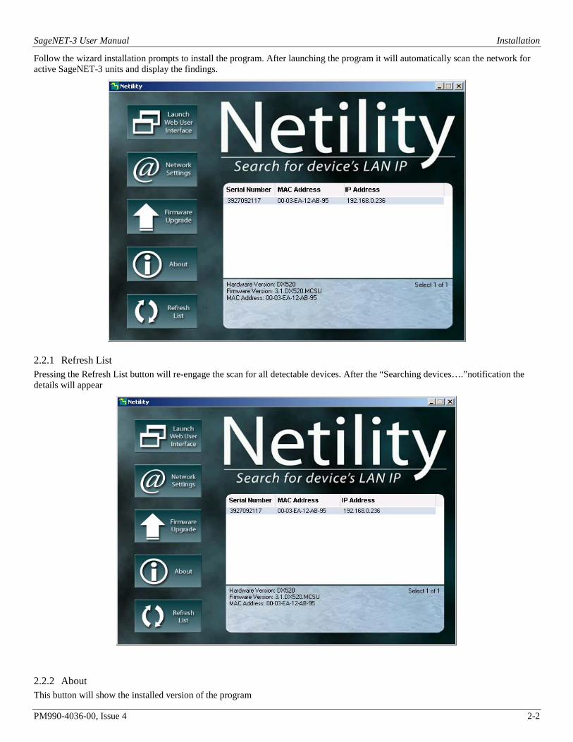
Follow the wizard installation prompts to install the program. After launching the program it will automatically scan the network for active SageNET-3 units and display the findings.
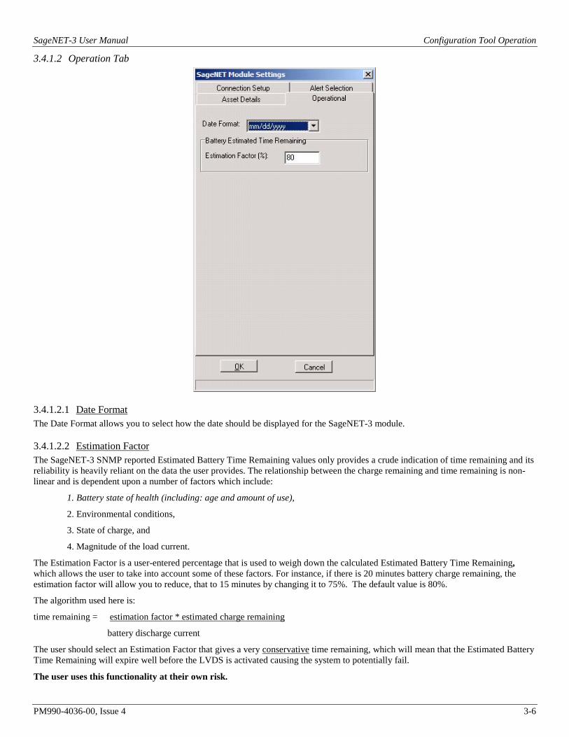
2.2.1 Refresh List Pressing the Refresh List button will re-engage the scan for all detectable devices. After the “Searching devices….”notification the details will appear
2.2.2 About This button will show the installed version of the program

SageNET-3 User Manual Installation
PM990-4036-00, Issue 4 2-3
2.2.3 Network Settings A particular IP Address can be assigned to the unit using the Network Setting button.
2.2.3.1 IP Address
The IP Address tab allows the network settings to be configured. The settable parameters are:
Obtain an IP address This field selects whether the SageNET-3 IP address is set manually or via DHCP. The network settings can be automatically obtained if there is a DHCP server on the network.
IP Address This field is to set SageNET-3 IP address.
Subnet Mask This field is to set SageNET-3 Subnet Mask.
Gateway This field is to set SageNET-3 Gateway.
The above 4 fields can be set via the SageNET-3 webpage as well. SageNET-3 will reboot after any of the above are changed.

SageNET-3 User Manual Installation
PM990-4036-00, Issue 4 2-4
2.2.3.2 Advanced
The Advance tab allows the network management features of the SageNET-3 to be configured. This allows the security of the unit to be managed. The settable parameters are:
Enable HTTP Function This field controls whether the SageNET-3 webpage can be accessed via the HTTP protocol. HTTP port number field defines what port is used for the HTTP protocol. The default is 80.
Enable HTTPS Function This field controls whether the SageNET-3 webpage can be accessed via the HTTPS protocol. HTTPS port number field defines what port is used for the HTTS protocol. The default is 443.
Enable Telnet Function This field controls whether the SageNET-3 Telnet functionality is operational. Telnet port number field defines what port is used for the Telnet protocol. The default is 23.
Enable SSH Function This field controls whether the SageNET-3 Secure Shell (Secure Telnet) functionality is operational. SSH port number field defines what port is used for the SSH protocol. The default is 22.
NOTE: The security of the SNMP system is managed via the unit’s webpage.

SageNET-3 User Manual Installation
PM990-4036-00, Issue 4 2-5
2.2.3.3 Password The password tab enables the device protection against an unauthorised access.
To enable this security, tick the Enable password setting field and type the chosen password twice for verification.
The password can be up to 24 alphanumeric characters (NB not special characters) in length; however the user can select something shorter. The password can be any combination of letters and numbers and it is case sensitive.
After pressing OK the unit will reset and all the Netility settings will be password protected.
For example if the user decides to eliminate the password by unticking the Enable password setting

SageNET-3 User Manual Installation
PM990-4036-00, Issue 4 2-6
the password dialog box will pop-up
The user should type the correct password and press the OK tab to continue with desired action. If the wrong password has been the entered, system will complain and nothing will change.
Note: The Netility password will have NO effect on Webpage access to the SageNET-3 unit.
2.3 LAUNCH WEB USER INTERFACE The web interface may be accessed via the web address: http://<ip-address-of-module>/ or from Netility utility.

SageNET-3 User Manual Installation
PM990-4036-00, Issue 4 2-7
The default view is Information-> System Status.
The Information->Current Status will give the user status information on the operation of the Sageon Power Plant.
2.4 INSTALLING THE SAGENET-3 CONFIGURATION TOOL If you are using Windows XP/Vista/7/8, please ensure you are logged into an account with administrative access before installing. If you are not sure, please consult your network administrator.
1. Insert the CD into the CD-ROM drive.
2. The CD will auto-play to install the configuration software
3. Follow the prompts during the installation procedure.
At the completion of installation, a SageNET-3 Configuration shortcut icon will be added to the Start/Program menu.

SageNET-3 User Manual Installation
PM990-4036-00, Issue 4 2-8
2.4.1 Running the SageNET-3 Configuration Tool for the first time If you are using Windows XP/Vista/7/8 it is advised that you run the program under the username with which you will mostly run the program in the future.
2.4.2 Logging Into the SageNET-3 Configuration Tool The Security dialog box will appear every time you run the configuration tool. It is to ensure that no unauthorised user can log in to the system. This prevents unauthorised users from making critical changes to any SageNET-3 units.
The default password is available by contacting field service. Please change the default password immediately by accessing the User Management option of the Tools menu (see User Management).
NOTE:
Every attempt to log in to the application is logged in the system event log, and also sent to a syslog server on the network. (Reporting Options, for more details on Reporting Options).
2.5 INSTALLING THE SAGENET-3 MIB The SageNET-3 MIB file has been pre-loaded in-to the device to allow integration into the user’s Network Management System NMS.
Location Location
Location

SageNET-3 User Manual Configuration Tool Operation
PM990-4036-00, Issue 4 3-1
3. CONFIGURATION TOOL OPERATION
3.1 INTRODUCTION The SageNET-3 Configuration Tool allows users to keep track of the configuration of each SageNET-3 module, on one or more PC’s. This tool allows the user to create regions and locations, and organise these units in a tree structure, for easy sorting and maintenance.
Using this tool, the user can download the configuration from, or upload the configuration to any SageNET-3 module that it has network access to. This may range from a SageNET-3 unit on a local area network (LAN), to using a wide area network (WAN) such as the Internet to access a module on the other side of the world.
All the configuration information for each module is saved onto the local hard disk, and can be backed up accordingly.
The configuration utility also provides traceability, as it logs important information to the system event log, and can also be configured to send syslog messages to a network syslog server.
3.2 THE MAIN SCREEN The main screen allows the user to create and maintain many SageNET-3 modules, in various locations. It can show the configuration for each module listed, and gives access to edit each module’s settings via the menu system.
3.2.1 The Module Tree The module tree allows the user to define an organisational tree, listing all the SageNET-3 modules that will be accessed by the configuration tool. Using the Add Region and Add Branch buttons, the user can define regions based on geographical location, or logistical information. The user can delete a region or branch by selecting the item and pressing the delete key or using the Delete item on the right-click pop-up menu.
3.2.2 The Module Information Area There are 4 important sections of the Site Information area.
3.2.2.1 Module Name The module name is a configurable label set by the user.
Location Location
Location

SageNET-3 User Manual Configuration Tool Operation
PM990-4036-00, Issue 4 3-2
3.2.2.2 IP Address The IP Address of the module that you wish to connect to, is set here.
TIP: If you wish to upload the same module configuration to more than one unit, create a template and upload to each unit by adjusting the IP Address each time.
3.2.2.3 Port No. The port that the configuration utility will connect to is set here. This is the port you wish to connect to during the next configuration upload or download.
TIP: This detail needs to be changed when you change the configuration port of the SageNET-3.
*WARNING* The configuration port that the SageNET-3 module uses is NOT changed here. To change the configuration port the SageNET-3 module uses, refer to SageNET-3 Configuration Tool TCP/IP Port.
3.2.2.4 Module Information Window The module information window allows the user to quickly view a module’s settings. This section will give you a break down of all the settings that can be changed via the Module Properties menu. There is some additional data displayed in the site information window. These details are saved locally on the PC, and are not transferable between SageNET-3 and the configuration tool.
3.3 PULL-DOWN MENUS The pull-down menus provide access to all the user selectable functions of the SageNET-3 configuration tool. This section describes the function of each pull-down menu and its sub-items.
3.3.1 File Menu The File menu provides the ability to print hardcopies of module settings, save the configuration information, and exit the program.
The functions available in the File Menu in listed order are as follows:
3.3.1.1 Save Saves any changes to module configurations to the local disk for future reference. The user will be asked to save on exit, but to safe guard changes in the meantime, they should use the Save menu option on a periodic basis.
3.3.1.2 Print Prints the currently selected Site Information. The Print Dialogue appears, allowing the user to select the appropriate printer and print properties.
3.3.1.3 Exit Exits the SageNET-3 configuration tool and returns to the operating system
3.3.2 Module Menu The Module menu provides access to the configuration properties and functions of the SageNET-3 Module selected.
The functions available in the Module Menu in listed order are as follows:

SageNET-3 User Manual Configuration Tool Operation
PM990-4036-00, Issue 4 3-3
3.3.2.1 Properties Opens the module parameters window that displays and allows editing of the currently selected SageNET-3 module parameters. See SageNET-3 Module Settings Window for further detail.
3.3.2.2 Configuration From SageNET-3 Creates a connection to the currently selected SageNET-3 module, and downloads the live configuration information from the module.
3.3.2.3 Configuration To SageNET-3 Creates a connection to the currently selected SageNET-3 module, and uploads the configuration information to the module.
This operation will result in the SageNET-3 module resetting, and is logged in the system event log, and to the syslog server, if configured.
3.3.3 Tools Menu The Tools menu provides access to the program options of the SageNET-3 configuration tool.
3.3.3.1 User Management Opens the User Management window. This window allows the user to add or delete users, and edit user information. For more information please see User Management Window..
3.3.3.2 Reporting Options Opens a window that allows the user to set the syslog reporting address. This should be the IP address of a syslog server on the network. The syslog server will then receive notifications of events, such as opening and closing of the program, user logins, changing of user information, changing of module configurations, and uploads and downloads of configurations.
3.4 POP UP WINDOWS Several parameter windows have been mentioned in the previous sections where system-operating parameters are displayed and able to be edited. The parameter windows and the function of their listed parameters are described in this section.
Locatio

SageNET-3 User Manual Configuration Tool Operation
PM990-4036-00, Issue 4 3-4
3.4.1 SageNET-3 Module Settings Window
3.4.1.1 Asset Details Tab The asset details tab provides the ability to change any details that may be required by the user to assist with asset tracking. The asset tracking details are reported via SNMP, and allow the user to discover information about the unit, such as it’s physical location, that can be accessed directly via the unit, and no external source.
3.4.1.1.1 Manufacturer This is the manufacturer of the SageNET-3 Unit. It corresponds to the manufacturer variable in the SNMP MIB, allowing you to configure each SageNET-3 unit’s manufacturer name.
3.4.1.1.2 Model The model corresponds to the model type of the SageNET-3 unit. Typically, this will be SageNET-3, however this may change for your unit, if you wish to rename the model.
3.4.1.1.3 Name The name of the system in your power network may be stored here, for usage in the SageNET-3 SNMP MIB.
3.4.1.1.4 Attached Devices This is the area where you may describe any attached devices for reporting via SNMP. For instance, you may wish to show that it is a system consisting of UNIPOWER rectifiers.
3.4.1.1.5 Asset Tag
Location

SageNET-3 User Manual Configuration Tool Operation
PM990-4036-00, Issue 4 3-5
The asset tag area is a place to keep track of the asset tag of the SageNET-3 unit. It may be up to 15 alphanumeric characters.
3.4.1.1.6 Install Date The install date allows you to keep track of when the power system or SageNET-3 unit was installed.
3.4.1.1.7 Maintenance Date The Maintenance date allows you to keep track of the last time any maintenance was performed on the SageNET-3 unit, or on the power supplies.
3.4.1.1.8 Build State The build state allows the administrator to effectively describe what release version and patches have been uploaded to the SageNET-3 module.
3.4.1.1.9 Latitude/Longitude The Latitude and Longitude sections allow you to keep track of the co-ordinates of the system, for mapping to a larger system. These values are entered in degrees, but are displayed in GPS format when reported by the SNMP interface. To convert between the GPS format and degrees, you need to use the following equations:
For Latitude: Latitude in Degrees = (gpsLatitude * 90) / ((231)-1)
The latitude is given as either a positive or negative. When a positive value is given, the latitude is north. When a negative value is given, the value is south.
For Longitude: Longitude in Degrees = (gpsLongitude * 180) / ((231)-1)
The longitude is given as either a positive or negative. When a positive value is given, the longitude is east. When the value is negative, the longitude is west.
3.4.1.1.10 Location Location allows you to describe where the module or power supply is situated. This could be an address, or an office, etc.
SageNET-3 User Manual Configuration Tool Operation
PM990-4036-00, Issue 4 3-6
3.4.1.2 Operation Tab
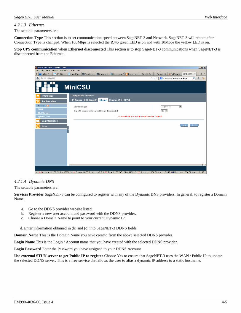
3.4.1.2.1 Date Format The Date Format allows you to select how the date should be displayed for the SageNET-3 module.
3.4.1.2.2 Estimation Factor The SageNET-3 SNMP reported Estimated Battery Time Remaining values only provides a crude indication of time remaining and its reliability is heavily reliant on the data the user provides. The relationship between the charge remaining and time remaining is non-linear and is dependent upon a number of factors which include:
1. Battery state of health (including: age and amount of use),
2. Environmental conditions,
3. State of charge, and
4. Magnitude of the load current.
The Estimation Factor is a user-entered percentage that is used to weigh down the calculated Estimated Battery Time Remaining, which allows the user to take into account some of these factors. For instance, if there is 20 minutes battery charge remaining, the estimation factor will allow you to reduce, that to 15 minutes by changing it to 75%. The default value is 80%.
The algorithm used here is:
time remaining = estimation factor * estimated charge remaining
battery discharge current
The user should select an Estimation Factor that gives a very conservative time remaining, which will mean that the Estimated Battery Time Remaining will expire well before the LVDS is activated causing the system to potentially fail.
The user uses this functionality at their own risk.

SageNET-3 User Manual Configuration Tool Operation
PM990-4036-00, Issue 4 3-7
3.4.1.3 Connection Setup
3.4.1.3.1 SageView TCP/IP Port 1 & 2 The SageView TCP/IP port settings allow you to configure which ports the SageNET-3 should listen on for a connection from the SageView program. These are configurable, so that you can set these to match ports that can be opened on any firewall(s) between the SageNET-3 module and the monitoring PC. It is recommended that you use ports 10001 and 10002 where possible. However, if these ports are unavailable, you should choose carefully what ports are used.
3.4.1.3.2 SageNET-3 Configuration Tool TCP/IP Port This port allows you to change what port the configuration tool should connect to the next time it connects to the SageNET-3 module. This is configurable, to allow for firewalls.
3.4.1.3.3 Battery Discharge Logging TCP/IP Connection The Battery Discharge Logging TCP/IP connection describes which SageView port will be used to report any discharge logs. Only one SageView session can receive the battery discharge information.
3.4.1.3.4 Default Access Code To provide security for remote access to the Sageon Control Unit (plant controller), a unique access code may be entered into the plant controller. This code defaults to 000000 from the factory. If the access code for the power plant has been changed from the factor default, it should be entered here so that SageNET-3 may gain remote access to the SCU.
For example, if the SCU has an access code of 2453242, then the user could set the default access code of the SageNET-3 module to 2453242.

SageNET-3 User Manual Configuration Tool Operation
PM990-4036-00, Issue 4 3-8
3.4.1.4 Alert Selection
3.4.1.4.1 Alert Selection Section The alert selection section allows you to choose which of the available alarms will be reported via SNMP traps. If the alarm is unselected, it will still be available via the alarm logs of the SNMP monitoring and the SageView monitoring, but it will not have an SNMP trap generated for it.
3.4.1.4.2 Select All The select all button will quickly select all of the alarms to be reported.
3.4.1.4.3 Select None The select none button will quickly remove all alarms from reporting.

SageNET-3 User Manual Configuration Tool Operation
PM990-4036-00, Issue 4 3-9
3.4.2 User Management Window
The user management window is used to maintain the users allowed to access the configuration tool. After the initial installation of the program, it is highly recommended that you change the administrator password from the default.
Any changes made to the users database is automatically logged in the system event logs, and if configured, is logged using the syslog protocol, to the set up syslog server.
3.4.2.1 Full Name The full name of the user is inserted here.
3.4.2.2 User Name The user name of the user is what the user will use to log into the configuration tool.
3.4.2.3 Password / Confirmation Password You need to type the user’s password into these sections to set the password for the user.
3.4.3 Reporting Options
You may insert the IP address of a computer that runs a syslog daemon here. This allows you to remotely monitor changes made to SageNET-3 configurations, and the user management of the configuration software from a remote computer.

SageNET-3 User Manual Web Interface
PM990-4036-00, Issue 4 4-1
4. WEB INTERFACE The web interface may be accessed via the web address: http://<ip-address-of-module>/. The operation of the webpage interface is described in detail in the following section. By default the SageNET-3 webpage opens at the Information -> System Status page.
4.1 INFORMATION SECTION
4.1.1 System Status
4.1.1.1 System Information tab This section is to show SageNET-3 system information. Values in Hardware Version/Firmware Version/Serial Number/System Time, are provided by SageNET-3 itself. Other values are user settings from the Configuration pages.
4.1.1.2 Network Status Tab This section is to show SageNET-3 Network settings. The MAC address is provided by SageNET-3. All other values in this section are user settings from the Configuration pages.

SageNET-3 User Manual Web Interface
PM990-4036-00, Issue 4 4-2
4.1.2 Current Status Current Status view shows Voltage, Current and Number of alarms of Sageon Power Plant.
Status refresh rate is settable by the pull down menu.
4.2 CONFIGURATION The Configuration section has the following options:

SageNET-3 User Manual Web Interface
PM990-4036-00, Issue 4 4-3
4.2.1 Network The user should read and understand the section Appendix - Network Setup before they configure the network settings.
The Configuration-> Network section has the following tabs:
4.2.1.1 IP Address This tab is accessed by default at Configuration - > Network menu in the selection area on the left
The settable parameters are:
IP Address This field is to set SageNET-3 IP address.
Subnet Mask This field is to set SageNET-3Subnet Mask.
Gateway This field is to set SageNET-3 Gateway.
Obtain an IP address This field is to choose to set SageNET-3 IP address manually or via DHCP.
The above 4 fields can be set in Netility utility as well. SageNET-3 will reboot after any of the above are changed.
The implemented choices for IP address selections are statically, by user selection and dynamically, by using the DHCP (Dynamic Host Configuration Protocol), with pull-down menu.

SageNET-3 User Manual Web Interface
PM990-4036-00, Issue 4 4-4
4.2.1.2 DNS Server IP The settable parameters are:
Primary DNS Server IP This section is to set SageNET-3 primary DNS Server IP address.
Secondary DNS Server IP This section is to set SageNET-3 secondary DNS Server IP address. SageNET-3 will use the secondary DNS Server IP address when the Primary DNS Server IP address is not working.
SageNET-3 User Manual Web Interface
PM990-4036-00, Issue 4 4-5
4.2.1.3 Ethernet The settable parameters are:
Connection Type This section is to set communication speed between SageNET-3 and Network. SageNET-3 will reboot after Connection Type is changed. When 100Mbps is selected the RJ45 green LED is on and with 10Mbps the yellow LED is on.
Stop UPS communication when Ethernet disconnected This section is to stop SageNET-3 communications when SageNET-3 is disconnected from the Ethernet.
4.2.1.4 Dynamic DNS The settable parameters are:
Services Provider SageNET-3 can be configured to register with any of the Dynamic DNS providers. In general, to register a Domain Name;
a. Go to the DDNS provider website listed. b. Register a new user account and password with the DDNS provider. c. Choose a Domain Name to point to your current Dynamic IP
d. Enter information obtained in (b) and (c) into SageNET-3 DDNS fields
Domain Name This is the Domain Name you have created from the above selected DDNS provider.
Login Name This is the Login / Account name that you have created with the selected DDNS provider.
Login Password Enter the Password you have assigned to your DDNS Account.
Use external STUN server to get Public IP to register Choose Yes to ensure that SageNET-3 uses the WAN / Public IP to update the selected DDNS server. This is a free service that allows the user to alias a dynamic IP address to a static hostname.

SageNET-3 User Manual Web Interface
PM990-4036-00, Issue 4 4-6
4.2.1.5 PPPoE The settable parameters are:
When Connection should be made This is to set if using PPPoE to connect with Sageon Power Plant. The options are:
Disabled: Default setting.
Connect always: SageNET-3 will automatically dial up and maintain continuous connection.
Login Name Enter the login name assigned by your ISP.
Login Password Enter the password assigned by your ISP.
Use this option to allow SageNET-3 to connect to the Internet directly using your xDSL modem. Once set-up, SageNET-3 will connect directly to the Internet without going through a router.
Note: SageNET-3 will reboot if any configuration applies.

SageNET-3 User Manual Web Interface
PM990-4036-00, Issue 4 4-7
4.2.2 SNMP
4.2.2.1 MIB System The settable parameters are:
System Name This section is to give a name to a SageNET-3.
System Contact This section is to give a name to the administrator.
System Location This section is to set SageNET-3 location.

SageNET-3 User Manual Web Interface
PM990-4036-00, Issue 4 4-8
MIB System settings
will show up in System Information section

SageNET-3 User Manual Web Interface
PM990-4036-00, Issue 4 4-9
4.2.2.2 Access Control The settable parameters are:
Manager IP Address This section is to set the IP address that the administrator can manage SageNET-3 from. It is valid for up to 8 IP addresses. To manage SageNET-3 from any IP address, enter *.*.*.* into "Manager IP address".
Version This section is to set SNMP versions.
Community This section is to set a Community name for NMS. The community name has to be as the same as the setting in NMS.
Permission This section is to set authorities of administrators. Options are Read, Read/Write, and No Access.
User Name This section is to set SNMP user's account. (Only if use SNMPv3)
Password This section is to set SNMP user's password (Only if uses SNMPv3)
Authentication This section is to select between MD5 or SHA (Only if use SNMPv3)
Privacy This section is to select between DES or AES (Only if uses SNMPv3)
Description This section is for an administrator to make notes.
4.2.2.3 Trap Notification The settable parameters are:
Destination IP This section is to set receivers IP address for receiving traps sent by SageNET-3. It is valid for up to 8 IP Addresses.
Community This section is to set a Community name. The community name has to be the same as the setting in Access Control.
Severity This section is to set Trap receiver levels. There are three levels:
1. Information: To receive all traps. 2. Warning: To receive only “warning” and “severe” traps. 3. Severe: To receive only “severe” traps.
Accept This section is to set to receive a trap or not.
Description This section is for an administrator to make notes.
Events This section is to select events for SageNET-3 to send traps. Clicking on Select will open a Select Events List. Event Traps may be selected from this list.

SageNET-3 User Manual Web Interface
PM990-4036-00, Issue 4 4-10
4.2.2.4 SNMP UDP Port The settable parameters are:
SageNET-3 SNMP Port and Trap Receive Port
This section is to set the SNMP and Trap port. (SNMP default is UDP161 and Trap default port is UDP162)

SageNET-3 User Manual Web Interface
PM990-4036-00, Issue 4 4-11
4.2.3 Web / Telnet
4.2.3.1 User Account The settable parameters are:
User Name This section is to set a user name for SageNET-3 web pages. It is valid for up to 8 users. Users have to input the user name to get access to SageNET-3 web pages from a web browser.
Password This section is to set a password for SageNET-3 web pages. Users have to input the password to get access to SageNET-3 web pages from a browser. The password can be up to 24 alphanumeric characters (special characters are not allowed) in length; however user can select something shorter. The password can be any combination of letters and numbers and it is case sensitive.
Permission This section is to set users' authorizations of Read, or Read/Write.
IP Filter This section is to set a particular IP address. Users can only gain access to SageNET-3 web pages if they come from this IP address. If you want to manage SageNET-3 from any IP address, you can set it as *.*.*.*
Auto Logoff after Idle for _ minute(s) When user login to the webpage, if idle for X minute which configured, it will log out automatically.
Once the user enters the:
User Name: <login name>
Password: <login password>
and presses the Apply button, a security dialog box will be displayed for any Web access

SageNET-3 User Manual Web Interface
PM990-4036-00, Issue 4 4-12
The same security is applied for Telnet sessions. If the user does not enter a User Name and Password then they will not be able to log-in.
Once the user enters the correct User Name and Password then they will be able to gain access to the Telnet session.

SageNET-3 User Manual Web Interface
PM990-4036-00, Issue 4 4-13
4.2.3.2 SSL Information The settable parameters are:
SSL Public Key This is to upload the SSL public key.
SSL Certificate This is to upload the SSL certificate.
The parameters for display are:
Public Key Length This is the length in bits of the SSL public key. This defines the level of encryption security provided by the public key.
All SSL certificates will have this basic information: domain, validity period, and issuer and this is displayed on this page. The SSL certificate is issued to a specific domain name, and has a validity period (Valid From and Valid Until). The issuer of the certificate is also included (Issued By).
For example
Issued To: www.unipowerco.com
Issued By: Secure Certificate Authority
Valid From: 27/6/2013
Valid Until: 27/6/2018
SageNET-3 User Manual Web Interface
PM990-4036-00, Issue 4 4-14
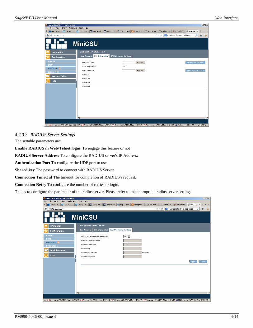
4.2.3.3 RADIUS Server Settings The settable parameters are:
Enable RADIUS in Web/Telnet login To engage this feature or not
RADIUS Server Address To configure the RADIUS server's IP Address.
Authentication Port To configure the UDP port to use.
Shared key The password to connect with RADIUS Server.
Connection TimeOut The timeout for completion of RADIUS's request.
Connection Retry To configure the number of retries to login.
This is to configure the parameter of the radius server. Please refer to the appropriate radius server setting.
SageNET-3 User Manual Web Interface
PM990-4036-00, Issue 4 4-15
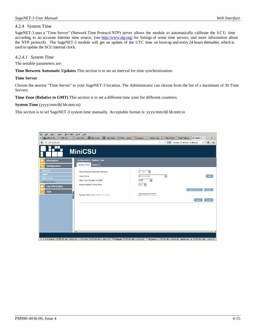
4.2.4 System Time SageNET-3 uses a "Time Server" (Network Time Protocol NTP) server allows the module to automatically calibrate the S C U time according to an accurate Internet time source, (see http://www.ntp.org/ for listings of some time servers, and more information about the NTP protocol). The SageNET-3 module will get an update of the UTC time on boot-up and every 24 hours thereafter, which is used to update the SCU internal clock.
4.2.4.1 System Time The settable parameters are:
Time Between Automatic Updates This section is to set an interval for time synchronization.
Time Server
Choose the nearest "Time Server" to your SageNET-3 location. The Administrator can choose from the list of a maximum of 30 Time Servers.
Time Zone (Relative to GMT) This section is to set a different time zone for different countries.
System Time (yyyy/mm/dd hh:mm:ss)
This section is to set SageNET-3 system time manually. Acceptable format is: yyyy/mm/dd hh:mm:ss

SageNET-3 User Manual Web Interface
PM990-4036-00, Issue 4 4-16
Synchronisation options are shown below
Time server can be selected from the list.
List can be edited by deleting the existing or adding the new device. Click the Edit button to get to the screen below

SageNET-3 User Manual Web Interface
PM990-4036-00, Issue 4 4-17
Type the name of the time server of choice. It can also be the IP address of a localised Microsoft Windows Server. Please see the Microsoft Windows Server on how to configure an authoritative time server in Windows Server.
For example: to configure a timer server at 192.168.0.27, the user should enter this IP address into the field.

SageNET-3 User Manual Web Interface
PM990-4036-00, Issue 4 4-18
Then the user should press the Add button and they will the new server added to the list
This time server that can be selected

SageNET-3 User Manual Web Interface
PM990-4036-00, Issue 4 4-19
The user then needs to configure the Time Zone Selection
Atlantic Time (Canada) is Greenwich Mean Time (GMT) - 3:00 Eastern Time (EST) is Greenwich Mean Time (GMT) - 4:00 Central Time (CST) is Greenwich Mean Time (GMT) - 5:00 Mountain Time (MT) is Greenwich Mean Time (GMT) - 6:00 Pacific Time (PST) is Greenwich Mean Time (GMT) - 7:00 Alaska Time (AKST) is Greenwich Mean Time (GMT) - 8:00 Hawaii Time(HST) is Greenwich Mean Time (GMT) - 10:00
And whether Day light correction can be applied or not
System time can also be entered manually with prescribed format. All the changes will be activated by pressing the Apply button. The synchronisation with the time server can be forced with Adjust Now >> button.

SageNET-3 User Manual Web Interface
PM990-4036-00, Issue 4 4-20
4.2.4.2 Restart The settable parameters are:
Auto Restart System for Every (0: Disable) Auto Restart System for Every n Minute(s) / Hour(s). Use this setting to auto restart the system at a predetermined interval. The default value is set to “0” (disabled). Enter between, 1 to 9999 Minute (i.e., between 1 minute or 166.65 hour) or 1 to 9999 Hour (1 hour to 416.6 days).
Manual Restart System After 30 Seconds Use this feature to manually restart the system SageNET-3 restart in about 30 seconds.
4.3 LOG INFORMATION Information fields are: Date/Time This is a record of the Date ( yyyy/mm/dd ) and Time ( hh:mm:ss ) that the event occurred.
Description
This is a description of the event.

SageNET-3 User Manual Web Interface
PM990-4036-00, Issue 4 4-21
Logs can be saved by pressing the Save button. That opens the dialog box with options so deal with the eventlog.csv file
Clear button will clear the log
4.4 HELP
4.4.1 Search SageNET-3 This will show all the detectable SageNET-3 on the network

SageNET-3 User Manual Web Interface
PM990-4036-00, Issue 4 4-22
4.4.2 Serial Port Debug Help - > Serial Port Debug Default format will be ASCII. Depending on the JAVA version installed on the PC after clicking on the Help - > Serial Port Debug, the JAVA authentication dialog box will appear and user will be required to enter the SageNET-3 username and password as per Web / Telnet.

SageNET-3 User Manual Web Interface
PM990-4036-00, Issue 4 4-23
After clicking on the window
and typing the password

SageNET-3 User Manual Web Interface
PM990-4036-00, Issue 4 4-24
the content will appear
If there is no password set then just the user permission to run the Java application will be requested.

SageNET-3 User Manual Web Interface
PM990-4036-00, Issue 4 4-25
Live traffic on device serial port will be visible.
Pressing clear will re-start the screen content.

SageNET-3 User Manual Web Interface
PM990-4036-00, Issue 4 4-26
4.4.3 About
4.4.3.1 About Help - > About will show the Firmware and Hardware version and the Serial number
4.4.3.2 Save / Restore Settings The user should click the Save button to save the configuration in their PC. The text file will have a default format of YYYY_MMDD_####.cfg. Administrator permissions are required.
Use Restore button function to restore a *.cfg configuration that has been saved earlier. The user should click the Browse… button to the location of the file and click the Restore button.

SageNET-3 User Manual Web Interface
PM990-4036-00, Issue 4 4-27
Save button dialog
SageNET-3 User Manual Web Interface
PM990-4036-00, Issue 4 4-28
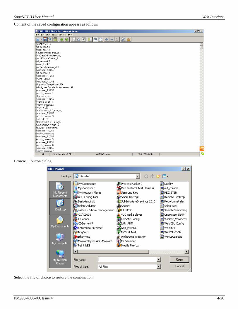
Content of the saved configuration appears as follows
Browse… button dialog
Select the file of choice to restore the combination.

SageNET-3 User Manual Web Interface
PM990-4036-00, Issue 4 4-29
4.4.3.3 Firmware Update Settings It is not recommended that this page be used. Please contact UNIPOWER Customer Support if the firmware needs to be updated.
Product support can be obtained using the following addresses and telephone numbers.
When contacting UNIPOWER, please be prepared to provide: 1. The charger model number, spec number, S build number, and serial number - see the equipment nameplate on the front panel 2. Your company’s name and address 3. Your name and title 4. The reason for the contact 5. If there is a problem with charger operation:
• Is the problem intermittent or continuous? • What revision is the firmware? • What actions were being performed prior to the appearance of the problem? • What actions have been taken since the problem occurred?
UNIPOWER, LLC 3900 Coral Ridge Drive Coral Springs, FL 33065 Phone: +1-954-346-2442 Toll Free: 1-800-440-3504 Web site – http://www.unipowerco.com

SageNET-3 User Manual SNMP
PM990-4036-00, Issue 4 5-1
5. SNMP
5.1 SNMP MIB STRUCTURE The SNMP MIB has a tree structure to group and describe the variables available to the user.
There are 13 overall sections to the SageNET-3 MIB.
For more information on each of the variables listed below, you can consult the description field in the MIB. This can generally be accessed from the NMS properties page for each leaf and branch in the tree.
5.1.1 psIdent The psIdent section contains all the system identification fields. These are all the fields that pertain to the asset management of the SageNET-3 module. The administrator using the configuration tool assigns these values.
5.1.2 csuStatus The csuStatus section contains the current status of the controller, and overall system. These fields are information about the system voltage, the total load current, and information about the incoming mains power.
It also contains a table, describing the status of the batteries. This table will always contain four rows, but the validity of the rows is dependant on the csNumBats variable, as this tells us how many batteries there are.
The table contains the following information:
• Battery number
• Battery current
• The estimated battery charge remaining
• The estimated battery time remaining (NOTE: This only provides a crude indication of battery time remaining and its reliability is heavily reliant on the data the user provides. The Battery Rating and the Estimation Battery Time Remaining Factor are key pieces of information that the user provides).
Location Location

SageNET-3 User Manual SNMP
PM990-4036-00, Issue 4 5-2
NOTE: The table always contains 4 rows; the relevancy of the data is dependant upon the number of batteries in the system.
5.1.3 csuTest The csuTest section holds the information about the last battery discharge test. It holds information about the time and date, length, and result of the battery discharge test.
This section also contains a table that holds the estimated battery charge remaining after the completion of the battery discharge test.
5.1.4 csuSysConfig The csuSysConfig holds the information about the configuration of the controller, which includes the options the controller has been configured with. This is presented as a table, which lists all configuration settings as SNMP objects in the range from scSysConfigSiteMonitor to scSysConfigTemperatureUnitFahrenheit.
5.1.5 csuParam csuParam holds all the information about the controller parameters. All values are read only, and include such parameters as, number of rectifiers, number of batteries, AC voltage high and low alarms settings.
5.1.6 csuAlarmLog The csuAlarmLog section holds the information of all currently active controller alarms.
1. The first readable variable is alLogSize, which contains the number of active alarms.
2. Secondly there is a table csuAlarmLogTable of each active alarm. For active alarm there is an entry containing:
• The log index;
• The alarm code;
• The descriptions as SNMP objects in the range from alAlarmEEPROMFail to alAlarmLogAlarm20Bit7; and
• The time the alarm was set in hundredths of a second relative to the system up time. NOTE: This is not the NTP synchronised time.
• The SCU Relay assignment. SCU alarms can be assigned as triggers for one of the 5 output relays. If the alarm has been assigned to more than one relay, then the first assignment is reported.
3. Thirdly there is a table csuAlarmLogTable containing a list of SCU Alarm Status entries. The table contains an entry for each alarm type and returns its status.. For active alarm the is an entry containing:
• The SCU Alarm code.
• The Alarm Status. This is either Inactive = 1 or Active = 2.
4. Fourthly there is an entry for the seconds of SCU clock. This can be used as “an alive” indication for the SCU and SageNET-3.
5. Finally there is an entry for each of the 20 alarm bytes of the SCU. Each entry has a value between 0 to 254 representing SCU alarm status bits 0 to 7.
5.1.7 smrStatus smrStatus contains information about the status of all the rectifiers in the power system. It contains the information for each rectifier, and the overall alarm log for the rectifiers. Both of these are presented in tables. Each line of the table for the status information includes:
• Rectifier index;
• Rectifier number for the entry;
• Rectifier current being used;
• Rectifier float voltage;
• Rectifier heat sink temperature; and
• Number of alarms active in the rectifier.
The alarm log table has 3 fields:

SageNET-3 User Manual SNMP
PM990-4036-00, Issue 4 5-3
• The Alarm log index for the table;
• The Rectifier number that each alarm corresponds to; and
• The Rectifier alarm descriptions as SNMP objects in the range from ssAlarmOutputVoltHigh to ssAlarmRectifierIoutHighResFlag.
5.1.8 smrParam smrParam contains information about the parameters of the RTP rectifiers connected to the system.
5.1.9 cellVoltages The cellVoltages section contains all the battery information and is reported via variables and a table. The overall system information, such as Cell Voltage High alarm, and configuration information is provided in this section.
Actual cell voltage information for each cell in the system is reported as a table including:
• The block index;
• The battery number;
• The block number; and
• The cell voltage.
5.1.10 siteMonitorStatus siteMonitorStatus covers all the site monitor status information for the power system. It reports back:
• Site Monitor analog channels current status table size;
• A table that contains:
o Site Monitor analog channel number;
o Site Monitor analog channel current value;
• Site Monitor digital channels current values table size;
• A table that contains:
o Site Monitor digital channel number;
o Site Monitor digital channel current value;
• The status of Site Monitor Output Relay control 1 to 4;
• The Site Monitor Alarm Log Size;
• A table for the Site Monitor Alarm Log containing:
o Site Monitor alarm index;
o Site Monitor alarm code;
• Site Monitor alarm description as SNMP objects in the range from smsSMAlarmAnalogChan1 to smsSMAlarmDigitChan12.
5.1.11 siteMonitorParam The siteMonitorParam branch contains the set-up and configuration information for the site monitor peripherals. It includes the following information:
• Site Monitor Enabled;
• Site Monitor Analog Parameters Size;
• A table to describe the site monitor analog parameters, containing:
o Site Monitor analog channel number;
o Site Monitor analog channel alarm enable;

SageNET-3 User Manual SNMP
PM990-4036-00, Issue 4 5-4
o Site Monitor analog channel full scale rating;
o Site Monitor analog channel upper alarm threshold;
o Site Monitor analog channel lower alarm threshold;
o Site Monitor user description label for this analog channel;
o Site Monitor unit label for this analog channel;
o Site Monitor output relay control 1 to 4 for this analog channel;
• Site Monitor digital channel parameter values table size;
• A table of the Site Monitor digital channel parameters, containing:
o Site Monitor digital channel number;
o Site Monitor digital channel alarm enable;
o Site Monitor user description label for this digital channel;
o Site Monitor normal state for this digital channel;
o Site Monitor output relay control 1 to 4 set-up for this digital channel.
5.1.12 csuTraps SageNET-3 implements 6 traps, which notify a NMS of alarms in the power system. An explanation of each of these traps is detailed below.
NOTE: SageNET-3 implements SNMPv1 traps.
5.1.12.1 csuTrapOnBattery This trap is a notification that the system is operating on battery power. This trap is persistent and is resent at one minute intervals until either the batteries are discharged or the system is no longer running on battery. It reports the number of batteries present in the system (up to 4) and the charge remaining for all 4 possible batteries. The charge remaining for non-existent batteries should be ignored.
5.1.12.2 csuTrapOnBDTCompleted This trap is a notification that a Battery Discharge Test has been completed. It reports the test results as an integer (see ctLastDischargeTestResult variable):
1: ldtFailed(1)
2: ldtPassed(2)
3: ldtNotAvailable(3)
4: ldtLowLoad(4)
Location

SageNET-3 User Manual SNMP
PM990-4036-00, Issue 4 5-5
5: ldtRectifierOverload(5)
6: ldtNoControl(6)
7: ldtUserTerminated(7)
8: ldtACLost(8)
9: ldtCellVoltageLow(9)
10: ldtBatteryCTFailed(10)
11: ldtUnknown(11)
5.1.12.3 csuTrapAlarmLogEntryAdded and csuTrapExtAlmLogEntryAdded This trap is a notification that an alarm has been inserted into the alarm table (see csuAlarmLog variable). It reports the alarm code and description as an SNMP object in the range from alAlarmEEPROMFail to alAlarmLogAlarm20Bit7. Only the alarms selected by the user using the configuration tool are reported. csuTrapExtAlmLogEntryAdded provides addition information about the relay assigned to the alarm.
5.1.12.4 csuTrapAlarmLogEntryRemoved and csuTrapExtAlmLogEntryRemoved This trap is a notification that an alarm has been removed from the alarm table (see csuAlarmLog variable). It reports the alarm code and description as an SNMP object in the range from alAlarmEEPROMFail to alAlarmLogAlarm20Bit7. csuTrapExtAlmLogEntryRemoved provides addition information about the relay assigned to the alarm.
5.1.12.5 csuTrapCSUParameterChange This trap is a notification that a SCUparameter has been changed from the front panel. It reports 2 variables that are currently not used cpCSUParameterUserName and cpCSUParameterChangedDesc.
5.1.12.6 csuTrapCSUOffline This trap is a notification that the SNMP interface has lost contact with the SCU (power system monitoring unit). This trap is persistent and is resent at one-minute intervals until communications have been restored.
5.1.12.7 csuTrapDailyCallup This trap is a notification that the SCU (power system monitoring unit) has sent out a daily callup which has not been acknowledged.
5.1.12.8 csuTrapEmergencyCallup This trap is a notification that the SCU (power system monitoring unit) has sent out an emergency callup which has not been acknowledged."
5.1.12.9 csuTrapCellCallup This trap is a notification that the SCU (power system monitoring unit) has sent out a cell callup which has not been acknowledged."
5.1.13 release The release branch contains all the current release information of the SNMP MIB tree. It contains contact information and version information of the MIB.

SageNET-3 User Manual SageView Connectivity
PM990-4036-00, Issue 4 6-1
6. SAGEVIEW CONNECTIVITY SageNET-3 now allows you to connect 2 copies of SageView to each Sageon Control Unit (SCU). The ports that SageView connects to are configurable via the SageNET-3 configuration tool’s connection options (see Connection Setup). The default settings for the SageView TCP connection ports are 10001 and 10002. This requires that any firewalls between the SageNET-3 module and the SageView program must have these ports open for use. Please see your network administrator with any problems.

SageNET-3 User Manual TELNET & SSH
PM990-4036-00, Issue 4 7-1
7. TELNET AND SSH SageNET-3 provides Telnet and SSH capability to setup the basic network parameters of the unit.
The user can access the Telnet system by typing telnet <ip-address-of-unit> at a Windows DOS command prompt or using any terminal program like PuTTY. The SSH system can also be access using a terminal program like PuTTY.
telnet <ip-address-of-unit> (for example: C:\>telnet 192.168.0.254)
The user will be then be presented with the following screen:
<<<<< SageNET-3 Setup Program >>>>>
Rectifier Technologies Pacific
Copyright(c) 2012. All Rights Reserved.
<<<<<--------------------------------------------->>>>>
Press any key to continue .......
After pressing any key the user will be asked for their user name.
User Name:
If the user name and password are not set already pressing the Enter Key will bring
User Name:
Password:
Pressing the Enter Key again will bring the Main Menu. If the User Name and Password are set already then only typing the exact text will allow the access to the Main Manu
<<<<< Main Menu >>>>>
<<<<<---------------------------------->>>>>
1. Set IP Address.
2. Set Web and Telnet User Account.
3. Reset Configuration to Default.
4. Save & Reboot.
0. Exit Without Saving.
Select =>
7.1 SET IP ADDRESS Entering the corresponding number will bring the associated Menu, for example typing the number1
Select => 1
will bring the Set IP Address menu
<<<<< Set IP Address >>>>>
<<<<<---------------------------------->>>>>
1. IP Address. (192.168.0.254)
2. Gateway Address. (192.168.0.1)
3. Subnet Mask. (255.255.255.0)
4. Obtain an IP address automatically. (By manual)
5. Primary DNS Server IP. (192.168.0.3)
6. Secondary DNS Server IP. (?)
0. Return to Main Menu.
Select =>

SageNET-3 User Manual TELNET & SSH
PM990-4036-00, Issue 4 7-2
Entering the corresponding number will bring the associated setup menu or return to the main one.
The values in brackets are showing the current state.
7.1.1 IP Address The IP address must be set to a unique value in the user’s network. See Appendix - Network Setup for more information about IP Addressing.
Note: The SageNET-3 module cannot connect to the network if the assigned IP address is already in use by another device.
7.1.2 Gateway Address The gateway address, or router, allows communication to other LAN segments. The gateway address should be the IP address of the router connected to the same LAN segment as the SageNET-3 module. Note: The gateway address must be within the local network. If you select 2 and enter the Gateway Address Menu you have to type the value. If the user just presses enter, the field will become empty as in Set IP Address menu.
7.1.3 Subnet Mask A netmask defines the number of bits taken from the IP address that are assigned for the host section. Note: Class A: 24 bits; Class B: 16 bits; Class C: 8 bits. If you select 3 and enter the Subnet Mask Menu you have to type the value. If the user just presses enter the field will become empty as in Set IP Address menu.
7.1.4 Obtain and IP address automatically Entering this menu will give you following options:
Select => 4
Obtain an IP address automatically. (0:By manual 1:Using DHCP)
Selecting the number 1 will enable DHCP ( Dynamic Host Configuration Protocol). That means after rebooting the device will possibly obtain a different address than the one the user has already, especially if it is set manually.
The user will have to use the Netility utility to find the new one in the case of DHCP.
Selecting the number 0 will enable the user to set the IP address of the device manually.
7.1.5 Primary DNS server IP Similar to setting the IP address
7.1.6 Secondary DNS server IP Similar to setting the IP address
7.2 SET WEB AND TELNET USER ACCOUNT Entering the number 2 at Main Menu
Select => 2
will bring the Web and Telnet User Account menu
Web and Telnet User Account:
User Name Password Access Rights IP Address
----------------- ----------------- ----------------- ----------------
1) No Access
2) No Access
3) No Access
4) No Access

SageNET-3 User Manual TELNET & SSH
PM990-4036-00, Issue 4 7-3
5) No Access
6) No Access
7) No Access
8) No Access
<<<<< User Account >>>>>
<<<<<---------------------------------->>>>>
1. Add.
2. Delete.
0. Return to Main Menu.
Select =>
To add the user, type the number 1 and press Enter. Put the name and password.
Web and Telnet User Account:
User Name Password Access Rights IP Address
----------------- ----------------- ----------------- ----------------
1) No Access
2) No Access
3) No Access
4) No Access
5) No Access
6) No Access
7) No Access
8) No Access
<<<<< User Account >>>>>
<<<<<---------------------------------->>>>>
1. Add.
2. Delete.
0. Return to Main Menu.
Select => 1
User Name: user
Password: ****
After Enter, the user will be asked for password verification.
Web and Telnet User Account:
User Name Password Access Rights IP Address
----------------- ----------------- ----------------- ----------------
1) No Access
2) No Access
3) No Access
4) No Access
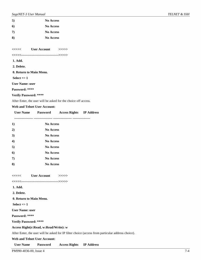
SageNET-3 User Manual TELNET & SSH
PM990-4036-00, Issue 4 7-4
5) No Access
6) No Access
7) No Access
8) No Access
<<<<< User Account >>>>>
<<<<<---------------------------------->>>>>
1. Add.
2. Delete.
0. Return to Main Menu.
Select => 1
User Name: user
Password: ****
Verify Password: ****
After Enter, the user will be asked for the choice off access.
Web and Telnet User Account:
User Name Password Access Rights IP Address
----------------- ----------------- ----------------- ----------------
1) No Access
2) No Access
3) No Access
4) No Access
5) No Access
6) No Access
7) No Access
8) No Access
<<<<< User Account >>>>>
<<<<<---------------------------------->>>>>
1. Add.
2. Delete.
0. Return to Main Menu.
Select => 1
User Name: user
Password: ****
Verify Password: ****
Access Right(r:Read, w:Read/Write): w
After Enter, the user will be asked for IP filter choice (access from particular address choice).
Web and Telnet User Account:
User Name Password Access Rights IP Address

SageNET-3 User Manual TELNET & SSH
PM990-4036-00, Issue 4 7-5
----------------- ----------------- ----------------- ----------------
1) No Access
2) No Access
3) No Access
4) No Access
5) No Access
6) No Access
7) No Access
8) No Access
<<<<< User Account >>>>>
<<<<<---------------------------------->>>>>
1. Add.
2. Delete.
0. Return to Main Menu.
Select => 1
User Name: user
Password: ****
Verify Password: ****
Access Right(r:Read, w:Read/Write): w
IP Address(*,0-255):
After Enter, the user will be returned to top menu
Web and Telnet User Account:
User Name Password Access Rights IP Address
----------------- ----------------- ----------------- ----------------
1) user **** Read/Write *.*.*.*
2) No Access
3) No Access
4) No Access
5) No Access
6) No Access
7) No Access
8) No Access
<<<<< User Account >>>>>
<<<<<---------------------------------->>>>>
1. Add.
2. Delete.
0. Return to Main Menu.
Select =>

SageNET-3 User Manual TELNET & SSH
PM990-4036-00, Issue 4 7-6
Select the number 0 to return to the Main Menu and than Quit with save.
7.3 RESET CONFIGURATION TO DEFAULT Entering the number 3 at Main Menu
Select => 3
will engage the Reset Configuration to Default.
Note: Take care since that enables DHCP selection of new web address and the user will need to use the Netility tool to find the new address after the reset.
7.4 SAVE & REBOOT Entering the number 4 at Main Menu
Select => 4
will bring the Save and Reboot menu
<<<<< Save & Reboot >>>>>
<<<<<------------------------------------------->>>>>
Would you like to save the settings and quit (Y/N)?
Pressing N will bring us back to the Main Menu
Pressing Y will reboot and terminate the connection.
<<<<< Save & Reboot >>>>>
<<<<<------------------------------------------->>>>>
Would you like to save the settings and quit (Y/N)? y
reboot
Connection to host lost.
C:\>
7.5 EXIT WITHOUT SAVING Entering the number 0 at Main Menu
Select => 0
will bring will bring the Web and Exit Without Saving menu
<<<<< Exit Without Saving >>>>>
<<<<<------------------------------------------->>>>>
Would you like to quit without saving (Y/N)?
Pressing N will bring the user back to Main Menu
Pressing Y will just terminate the connection.
<<<<< Exit Without Saving >>>>>
<<<<<------------------------------------------->>>>>
Would you like to quit without saving (Y/N)? y
Connection to host lost.
C:\>
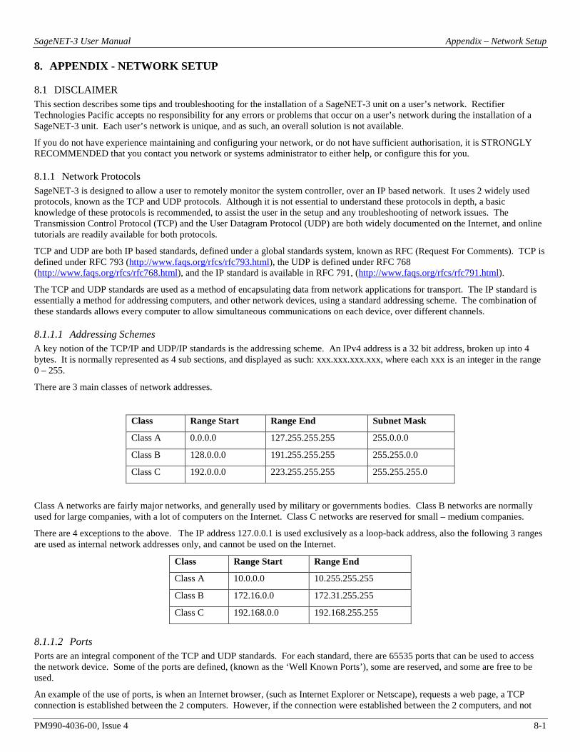
SageNET-3 User Manual Appendix – Network Setup
PM990-4036-00, Issue 4 8-1
8. APPENDIX - NETWORK SETUP
8.1 DISCLAIMER This section describes some tips and troubleshooting for the installation of a SageNET-3 unit on a user’s network. Rectifier Technologies Pacific accepts no responsibility for any errors or problems that occur on a user’s network during the installation of a SageNET-3 unit. Each user’s network is unique, and as such, an overall solution is not available.
If you do not have experience maintaining and configuring your network, or do not have sufficient authorisation, it is STRONGLY RECOMMENDED that you contact you network or systems administrator to either help, or configure this for you.
8.1.1 Network Protocols SageNET-3 is designed to allow a user to remotely monitor the system controller, over an IP based network. It uses 2 widely used protocols, known as the TCP and UDP protocols. Although it is not essential to understand these protocols in depth, a basic knowledge of these protocols is recommended, to assist the user in the setup and any troubleshooting of network issues. The Transmission Control Protocol (TCP) and the User Datagram Protocol (UDP) are both widely documented on the Internet, and online tutorials are readily available for both protocols.
TCP and UDP are both IP based standards, defined under a global standards system, known as RFC (Request For Comments). TCP is defined under RFC 793 (http://www.faqs.org/rfcs/rfc793.html), the UDP is defined under RFC 768 (http://www.faqs.org/rfcs/rfc768.html), and the IP standard is available in RFC 791, (http://www.faqs.org/rfcs/rfc791.html).
The TCP and UDP standards are used as a method of encapsulating data from network applications for transport. The IP standard is essentially a method for addressing computers, and other network devices, using a standard addressing scheme. The combination of these standards allows every computer to allow simultaneous communications on each device, over different channels.
8.1.1.1 Addressing Schemes A key notion of the TCP/IP and UDP/IP standards is the addressing scheme. An IPv4 address is a 32 bit address, broken up into 4 bytes. It is normally represented as 4 sub sections, and displayed as such: xxx.xxx.xxx.xxx, where each xxx is an integer in the range 0 – 255.
There are 3 main classes of network addresses.
Class Range Start Range End Subnet Mask
Class A 0.0.0.0 127.255.255.255 255.0.0.0
Class B 128.0.0.0 191.255.255.255 255.255.0.0
Class C 192.0.0.0 223.255.255.255 255.255.255.0
Class A networks are fairly major networks, and generally used by military or governments bodies. Class B networks are normally used for large companies, with a lot of computers on the Internet. Class C networks are reserved for small – medium companies.
There are 4 exceptions to the above. The IP address 127.0.0.1 is used exclusively as a loop-back address, also the following 3 ranges are used as internal network addresses only, and cannot be used on the Internet.
Class Range Start Range End
Class A 10.0.0.0 10.255.255.255
Class B 172.16.0.0 172.31.255.255
Class C 192.168.0.0 192.168.255.255
8.1.1.2 Ports Ports are an integral component of the TCP and UDP standards. For each standard, there are 65535 ports that can be used to access the network device. Some of the ports are defined, (known as the ‘Well Known Ports’), some are reserved, and some are free to be used.
An example of the use of ports, is when an Internet browser, (such as Internet Explorer or Netscape), requests a web page, a TCP connection is established between the 2 computers. However, if the connection were established between the 2 computers, and not

SageNET-3 User Manual Appendix – Network Setup
PM990-4036-00, Issue 4 8-2
ports of the 2 computers, the computers would then be effectively closed to any other incoming connections. So instead, the browser connects to a single port (in the case of HTTP, this is port 80). This allows both computers to still accept any incoming connections on any of the other open ports they have.
One good way to look at these ports is like doors to a building. You have an address for the building, which is your IP address, as described above. The ports then become the entries to the building. Without making a connection to the port, you cannot enter.
8.1.1.3 TCP versus UDP TCP and UDP are the most commonly used IP based protocols in operation today. They are however, different in their basic makeup.
TCP establishes a connection between 2 computers, which is held open for as long as the connection is needed. This is analogous to calling somebody on a telephone. Every packet is tracked through the network, and if any packets are lost, the protocol knows to request a resend of the packet immediately.
UDP sends a packet through the IP based network to the receiver, similar to sending a letter to somebody via postal mail. There is no connection made between the 2 computers, and no absolute assurance that the packet will reach the intended destination.
SageNET-3 uses both of these protocols for different tasks.
8.1.2 Network Setup & Troubleshooting When installing the SageNET-3 unit onto your network, you should ask some basic questions before beginning, which will assist you with the installation.
What IP Address should the unit be?
What is the Subnet mask?
What is the default gateway’s IP address?
Is there a firewall?
Do I use a proxy server?
8.1.2.1 SageNET-3 IP Address The IP Address of each SageNET-3 unit is static. This means it cannot be dynamically given an IP address on boot up, using a DHCP server. You need to assign an IP address to the unit, and ensure that the IP address you give it is unique on the network.
To assign an IP address to the SageNET-3 unit, see Network Settings.
8.1.2.2 Subnet Mask Each IP based network has a subnet mask used on it. The subnet mask usually corresponds to the class of the network, as described in Addressing Schemes. This will need to be changed to reflect the subnet mask used in your particular network.
TIP: Use the Windows™ command line tool ipconfig to discover your subnet mask.
8.1.2.3 Gateway IP Address The gateway IP address is required if you will be communicating with computers that are not on the current LAN connection. A gateway is generally a computer, router, or bridge, which connects a PC, or network device to another network, such as the Internet.
TIP: Use the Windows™ command line tool ipconfig to discover your gateway IP address.
8.1.2.4 Firewalls Firewalls are devices that block incoming (and sometimes outgoing) packets from accessing your network. It is a method of stopping any network ‘hacking’. In current day systems, firewalls are in common use with most Internet connections.
The way a firewall works, is it blocks any attempts to establish a connection with the network device. The connections are generally blocked when a PC or network device attempts to connect to the internal network from the Internet.
Using SageNET-3 across the Internet without any form of encryption is NOT recommended. All data transfer is in an unprotected state, and is vulnerable to attack. Remote access across the Internet should be done via a virtual private network (VPN).
To use SageNET-3 across the Internet, you must ensure that certain ports are available for connection. Most of these ports are configurable, such as the SageView connection ports and the SageNET-3 configuration. However, some ports are not configurable, such as the SNMP trap (UDP Port 162) and SNMP monitoring ports (UDP Port 161), and the HTTP connection ports (TCP Port 80).
To utilise the features of SageNET-3, you will need to ensure that all ports you decide to use are open to the Internet

SageNET-3 User Manual Appendix – Network Setup
PM990-4036-00, Issue 4 8-3
For a full list of the TCP and UDP port assignments, please refer to: http://www.iana.org/assignments/port-numbers
Each firewall has its own way of configuring ports for usage. Please refer to the firewall manuals for instructions on how to open ports.
8.1.2.5 Proxy Server A proxy server is a method of speeding up the loading of web pages, by caching (or keeping a copy of) the web page on a local server. It generally operates from an Internet Service Provider’s network, although some companies maintain their own. When a web page is loaded, it is cached into the proxy server. Then, if the same webpage is requested again within a certain time frame, the page from the proxy server is sent again, reducing the time to get the page.
You should avoid using a proxy server with the SageNET-3 unit. This is because when a proxy server is used, some of the pre-processing that occurs before the page is returned does not get redone, and as such, some changes that may have occurred, may not be reflected in the reloaded web page.
TIP: Internet Explorer allows the proxy setting to be switched off or excluded for particular IP addresses, under the Tools Menu, Options, Connections Tab, LAN Settings, Advanced.
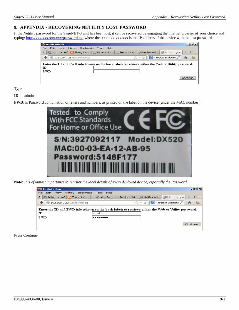
SageNET-3 User Manual Appendix – Recovering Netility Lost Password
PM990-4036-00, Issue 4 9-1
9. APPENDIX - RECOVERING NETILITY LOST PASSWORD If the Netility password for the SageNET-3 unit has been lost, it can be recovered by engaging the internet browser of your choice and typing: http://xxx.xxx.xxx.xxx/password.cgi where the xxx.xxx.xxx.xxx is the IP address of the device with the lost password.
Type
ID: admin
PWD: is Password combination of letters and numbers, as printed on the label on the device (under the MAC number).
Note: It is of utmost importance to register the label details of every deployed device, especially the Password.
Press Continue

SageNET-3 User Manual Appendix – Recovering Netility Lost Password
PM990-4036-00, Issue 4 9-2
For password reset press Clear All button (lost password is shown as Utility password above if it is to be kept)
Cleared password can be seen as un-ticked now
If the user can not tell the system password from the label then it need to be retrieved from the manufacturer / vendor by the unit serial number.
Note: The Netility password will have NO effect on Web Browser access.

SageNET-3 User Manual Appendix – SageNET-3 Firmware Update
PM990-4036-00, Issue 4 10-1
10. APPENDIX SAGENET-3 FIRMWARE UPDATE The firmware of the SageNET-3 unit can be updated using the Netility Tool.
Run the Netility Tool and allow it to find the SageNET-3 units on the network. Select the unit that needs to be updated. Press the Firmware Upgrade button. For the selected device, this button will invoke the new firmware file query
Navigate to the chosen file (by pressing the square button next to the File Name field). Navigate to the file of choice and press Open

SageNET-3 User Manual Appendix – SageNET-3 Firmware Update
PM990-4036-00, Issue 4 10-2
Press download
Progress will be indicated
Outcome will be reported in the Download Status
Press Cancel to finish the f/w update

SageNET-3 User Manual Appendix – TCP/IP Ports
PM990-4036-00, Issue 4 11-1
11. APPENDIX - TCP/IP PORTS The SageNET-3 uses the following TCP/IP ports for its communications interfaces:
PORT PROTOCOL
TCP Port 80# HTTP
TCP Port 443# HTTP over TLS/SSL
TCP Port 23# Telnet
TCP Port 22# SSH
TCP Port 10001* SageView software
TCP Port 10002* SageView software (secondary connection)
TCP Port 10099* Configuration Tool access to SageNET-3
TCP Port 37 Time server
TCP Port 161 SNMP
TCP Port 162 SNMP Traps
UDP Port 162 SNMP Traps
Note:
1. Ports marked with an asterisk (*) may be re-configurable using the SageNET-3 Configuration Program should a port conflict be encountered.
2. Ports marked with an hash (#) may be re-configurable using the SageNET-3 Netility Tool should a port conflict be encountered.
In order for a computer to access the SageNET-3 remotely, any networking equipment (routers, firewalls, p r o x y servers, e t c ...) between the two must b e configured to pass data on the appropriate TCP/IP port. If the SageNET-3 can be accessed via web browser (HTTP is the most universal TCP/IP protocol) but fails for one of the other protocols, then you should suspect a firewall or proxy server blocking TCP/IP ports to be the cause.

SageNET-3 User Manual SageNET-3 Quick Start Guide
PM990-4036-00, Issue 4 12-1
12. SAGENET-3 QUICK START GUIDE
12.1 MATERIALS REQUIRED 1. SageNET-3 board and installation CD
2. Computer running Windows XP or higher operating system
3. CAT5 network cable for SageNET-3 connection to your network
4. #1 Phillips Screwdriver
12.2 ADVANCE PREPARATION You will need the following network information to configure the SageNET-3.
1. Static IP Address for SageNET-3 Subnet Mask
2. IP Address of network gateway
3. IP Address of SNMP Monitoring (to receive SNMP traps) IP Address of SNTP time server (optional) 4. IP Address of system log server (optional) MAC address from label on SageNET-3 board
A configuration check sheet for recording these values is included at the end of this section.
You may configure the IP address of the SageNET-3 by using the Netility Tool. Details of both procedures may be found in Installing and using the Netility Utility sect ion of the SageNET-3 Manual. The Netility Tool must be instal led from the SageNET-3 installation CD.
To configure the IP address of the SageNET-3 device, the computer being used must be on the same physical network segment. This means that there should be no network segmenting equipment between the two devices (such as firewalls, gateways or filtering routers).
If the SageNET-3 device is to be accessed from another network segment (for monitoring or remote programming), certain TCP/IP ports must be accessible from the other network segment. In many installations only the commonly used TCP/IP ports such as HTTP, FTP, POP3, etc... are allowed to pass through the network segmenting equipment. It may be necessary to configure the network segmenting equipment to pass the unique TCP/IP ports required by SageNET-3. A more detailed discussion of TCP/IP ports may be found in Appendix - TCP/IP Ports section of the SageNET-3 Manual.
12.3 SAGENET-3 INSTALLATION OVERVIEW Confirm firmware revision level of Sageon Plant Controller. Install SageNET-3 board and connect
Using Netility Tool, configure the IP address, subnet mask and gateway for the SageNET-3 board.
Using the SageNET-3 Configuration Program, configure th e network monitoring system
Test access to SageNET-3 by directing a web browser to http://<ip-address-of- module>/. The SageNET-3 home web page should be seen.
Note:
Due to the compact size of the RJ45 socket on the SageNET-3 board, it is necessary to use an Ethernet cable constructed with premium quality RJ45 plugs. Poor connections have been observed when using cables constructed from discount or generic RJ45 plugs. Brand name cables such as those from AMPTM will assure proper operation of your SageNET-3.
If you are experiencing problems with your SageNET-3 board when it is properly installed, please check the link status LEDs on the RJ45 connector. If no LEDs are illuminated, a poor cable connection should be investigated.

SageNET-3 User Manual SageNET-3 Quick Start Guide
PM990-4036-00, Issue 4 12-2
SageNET-3 Setup Data Worksheet
Name of Installation:
SageNET-3 MAC Number:
____-____-____-____-____-____ (ex: 00-03-EA-12-AB-95)
SageNET-3 Static IP:
______.______.______.______ (ex: 192.168.0.11)
SageNET-3 Network Mask:
______.______.______.______ (ex. 255.255.0.0)
SageNET-3 Network Gateway:
______.______.______.______ (ex: 192.168.0.1)
Network Monitoring System: (where to send SNMP traps)
______.______.______.______ (ex: 192.168.0.121)
Network Time Server: (optional)

SageNET-3 User Manual Product Support
PM990-4036-00, Issue 4 13-1
13. PRODUCT SUPPORT In case of difficulties please call your local supplier.
Product support can be obtained using the following addresses and telephone numbers.
When contacting UNIPOWER, please be prepared to provide:
1. The charger model number, spec number, S build number, and serial number - see the equipment nameplate on the front panel
2. Your company’s name and address
3. Your name and title
4. The reason for the contact
5. If there is a problem with charger operation: • Is the problem intermittent or continuous? • What revision is the firmware? • What actions were being performed prior to the appearance of the problem? • What actions have been taken since the problem occurred?
UNIPOWER, LLC 3900 Coral Ridge Drive Coral Springs, FL 33065 Phone: +1-954-346-2442 Toll Free: 1-800-440-3504 Web site – http://www.unipowerco.com