Embed Size (px)
Citation preview
Classification: Internal Status: Draft Expiry date: 2009-12-18 Page 1 of 19
Safety Zone Application – Construction Phase
Sheringham Shoal Wind Farm Project
Classification: Internal Status: Draft Expiry date: 2009-12-18 Page 2 of 19
Title:
Safety Zone Application – Sheringham Shoal Wind Farm Project
Document no. : Contract no.: Project:
SC-1B-NH-F15-00004-01
Classification: Distribution:
Internal Corporate StatoilHydro
Expiry date: Status
2009-12-18 Draft
Distribution date: Rev. no.: Copy no.:
01
Author(s)/Source(s):
Myhre, Trude Elisabeth
Subjects:
Remarks:
Valid from: Updated:
Responsible publisher: Authority to approve deviations:
Techn. responsible (Organisation unit): Techn. responsible (Name): Date/Signature:
Trude Elisabeth Myhre
Responsible (Organisation unit): Responsible (Name): Date/Signature:
Anne Jorunn Røstum
Recommended (Organisation unit): Recommended (Name): Date/Signature:
Karstein Kviljo
Approved by (Organisation unit): Approved by (Name): Date/Signature:
Doc. No. Valid from Rev. no.
Classification: Internal Status: Draft Expiry date: 2009-12-18 Page 3 of 19
Table of contents 1 Introduction ............................................................................................................................4 1.1 Purpose of Document ..............................................................................................................4 1.2 Abbreviations ...........................................................................................................................4 2 Description of Installation.....................................................................................................4 2.1 General ....................................................................................................................................4 2.2 Location ...................................................................................................................................7 2.3 Operational Description..........................................................................................................10 2.4 Aviation and Navigational Marking.........................................................................................10 2.4.1 Temporary Navigational Marking ...........................................................................................10 2.4.2 Permanent Navigational Marking...........................................................................................11 2.4.3 Aviation Lighting.....................................................................................................................15 2.5 CDM Regulations...................................................................................................................16 3 Safety Zones.........................................................................................................................16 3.1 General ..................................................................................................................................16 3.2 Monitoring of Area..................................................................................................................18 3.3 Traffic Survey.........................................................................................................................18 4 Summary...............................................................................................................................19
Doc. No. Valid from Rev. no.
Classification: Internal Status: Draft Expiry date: 2009-12-18 Page 4 of 19
1 Introduction
1.1 Purpose of Document
Reference is made to the Section 36 consent received from the UK Government of Business, Enterprise and Regulatory Reform (BERR) for the Sheringham Shoal Wind Farm Project dated 7 August 2008 and signed Mr. Richard Mellish. With reference to “The Electricity (Offshore Generating Stations) (Safety Zones) (Application Procedures and Control of Access) Regulations 2007”, an application of Safety Zones related to the Sheringham Shoal Wind Farm Project has been prepared and is hereby submitted.
1.2 Abbreviations
ALARP - As Low As Reasonably Practicable ID - Identification KV - Kilovolt LAT - Lowest Astronomical Tide MW - Megawatt WTG - Wind Turbine Generator
2 Description of Installation
2.1 General
The Sheringham Shoal Offshore Wind Farm will be located in shallow waters approximately 17 to 23 km (9 – 12 nautical miles) from the north Norfolk coastal town of Sheringham and 5 km north of the offshore sand bank known as Sheringham Shoal. The wind farm shall have an installed power capacity of 315 MW and shall be equipped with Siemens SWT-3.6-107 wind turbine generators with power rating of 3.6 MW per unit. The land lease obtained from Crown Estate covers a wind farm area of approximately 35 km2. The wind farm power capacity of 315 MW will be formed by 88 standardized wind turbine generators (WTGs) with a unit capacity of 3.6 MW. The WTGs, consisting of nacelle and tower, are separated from each other and located in a pattern optimized for best energy yield taking into account environmental issues like certain bird species migration and possible subsurface restrictions like boat wrecks worthy of preservation or to avoid problematic soil conditions.
Doc. No. Valid from Rev. no.
Classification: Internal Status: Draft Expiry date: 2009-12-18 Page 5 of 19
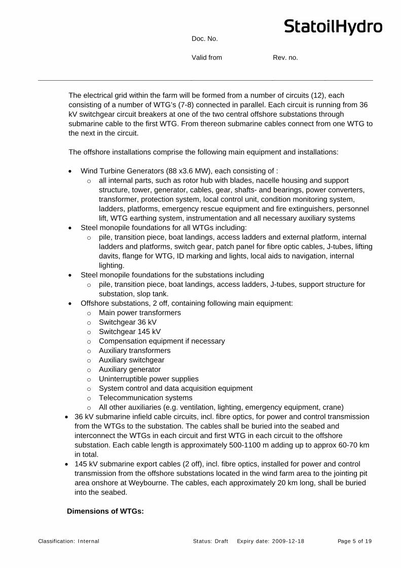
The electrical grid within the farm will be formed from a number of circuits (12), each consisting of a number of WTG’s (7-8) connected in parallel. Each circuit is running from 36 kV switchgear circuit breakers at one of the two central offshore substations through submarine cable to the first WTG. From thereon submarine cables connect from one WTG to the next in the circuit. The offshore installations comprise the following main equipment and installations: Wind Turbine Generators (88 x3.6 MW), each consisting of :
o all internal parts, such as rotor hub with blades, nacelle housing and support structure, tower, generator, cables, gear, shafts- and bearings, power converters, transformer, protection system, local control unit, condition monitoring system, ladders, platforms, emergency rescue equipment and fire extinguishers, personnel lift, WTG earthing system, instrumentation and all necessary auxiliary systems
Steel monopile foundations for all WTGs including: o pile, transition piece, boat landings, access ladders and external platform, internal
ladders and platforms, switch gear, patch panel for fibre optic cables, J-tubes, lifting davits, flange for WTG, ID marking and lights, local aids to navigation, internal lighting.
Steel monopile foundations for the substations including o pile, transition piece, boat landings, access ladders, J-tubes, support structure for
substation, slop tank. Offshore substations, 2 off, containing following main equipment:
o Main power transformers o Switchgear 36 kV o Switchgear 145 kV o Compensation equipment if necessary o Auxiliary transformers o Auxiliary switchgear o Auxiliary generator o Uninterruptible power supplies o System control and data acquisition equipment o Telecommunication systems o All other auxiliaries (e.g. ventilation, lighting, emergency equipment, crane)
36 kV submarine infield cable circuits, incl. fibre optics, for power and control transmission from the WTGs to the substation. The cables shall be buried into the seabed and interconnect the WTGs in each circuit and first WTG in each circuit to the offshore substation. Each cable length is approximately 500-1100 m adding up to approx 60-70 km in total.
145 kV submarine export cables (2 off), incl. fibre optics, installed for power and control transmission from the offshore substations located in the wind farm area to the jointing pit area onshore at Weybourne. The cables, each approximately 20 km long, shall be buried into the seabed.
Dimensions of WTGs:

Doc. No. Valid from Rev. no.
Classification: Internal Status: Draft Expiry date: 2009-12-18 Page 6 of 19
Foundation height 20 m above LAT Tower height 59.55 m Hub height 81.75 m above LAT Rotor diameter 107.2 m
Doc. No. Valid from Rev. no.
Classification: Internal Status: Draft Expiry date: 2009-12-18 Page 7 of 19
2.2 Location
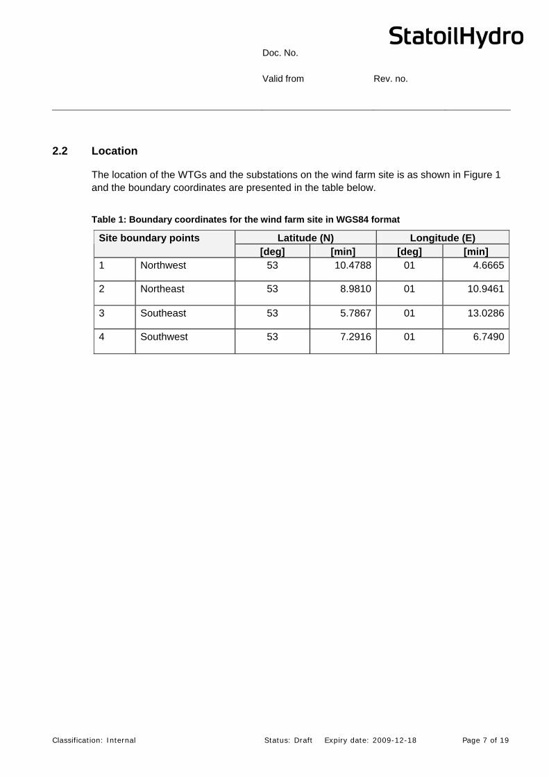
The location of the WTGs and the substations on the wind farm site is as shown in Figure 1 and the boundary coordinates are presented in the table below.
Table 1: Boundary coordinates for the wind farm site in WGS84 format
Latitude (N) Longitude (E) Site boundary points [deg] [min] [deg] [min]
1 Northwest 53 10.4788 01 4.6665
2 Northeast 53 8.9810 01 10.9461
3 Southeast 53 5.7867 01 13.0286
4 Southwest 53 7.2916 01 6.7490

Doc. No. Valid from Rev. no.
Classification: Internal Status: Draft Expiry date: 2009-12-18 Page 8 of 19
Figure 1: WTGs and Substations Location
Doc. No. Valid from Rev. no.
Classification: Internal Status: Draft Expiry date: 2009-12-18 Page 9 of 19
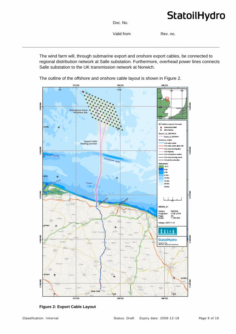
The wind farm will, through submarine export and onshore export cables, be connected to regional distribution network at Salle substation. Furthermore, overhead power lines connects Salle substation to the UK transmission network at Norwich. The outline of the offshore and onshore cable layout is shown in Figure 2.
Figure 2: Export Cable Layout
Doc. No. Valid from Rev. no.
Classification: Internal Status: Draft Expiry date: 2009-12-18 Page 10 of 19
2.3 Operational Description
The Sheringham Shoal Wind Farm will be operated as an unmanned installation. The only operational mode which will require manning will be regularly maintenance and required repairs. There will be regular maintenance activities of the WTGs and substations. The maintenance crew will consist of 20 offshore technicians on each day shift maintaining the wind farm on a seven day per week basis. The personnel will be transported to the WTGs and substations as required; the operation department will have four 12 pax WINDCAT type boats available for this operation. The work will only be performed during daytime; the boats will carry the crew out to the wind farm in the morning and back to shore in the afternoon. The maintenance crew will be able to run planned maintenance activities. If larger repairs are required, a separate jack-up vessel with a lifting crane which can lift heavy components will have to be mobilised. The WTGs and substations can be accessed by a ladder on the outside of the transition piece. Inside the WTG tower, there is a service lift for access to the nacelle. On each of the WTGs there is a davit crane on the transition piece platform and a crane inside the nacelle. This lifting gear is used for transfer of tools and equipment from the transfer boat to the relevant working area.
2.4 Aviation and Navigational Marking
Warning lighting and navigation aids shall be according to requirements by Civil Aviation Authority (CAA), Trinity House Lighthouse Service (THLS) and the Maritime and Coastguard Agency (MCA).
2.4.1 Temporary Navigational Marking
The following temporary marking has been agreed with THLS. Immediately prior to physical work on site commencing and until the site is marked in accordance with the permanent marking arrangements:
A pillar buoy exhibiting North Cardinal mark characteristics and exhibiting a VQ light to be established and maintained in position Latitude 53 deg 09’.913N., Longitude 01 deg 07’.686E
A pillar buoy exhibiting East Cardinal mark characteristics and exhibiting a VQ(3) 5s light to be established and maintained in position Latitude 53 deg 07’.318N., Longitude 01 deg 12’.287E
A pillar buoy exhibiting South Cardinal mark characteristics and exhibiting a VQ(6)+L Fl 10s light to be established and maintained in position Latitude 53 deg 06’.361N., Longitude 01 deg 10’.000E
Doc. No. Valid from Rev. no.
Classification: Internal Status: Draft Expiry date: 2009-12-18 Page 11 of 19
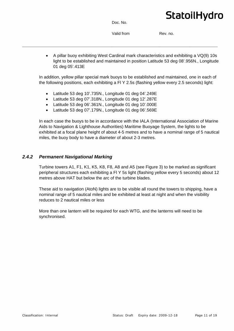
A pillar buoy exhibiting West Cardinal mark characteristics and exhibiting a VQ(9) 10s light to be established and maintained in position Latitude 53 deg 08’.956N., Longitude 01 deg 05’.413E
In addition, yellow pillar special mark buoys to be established and maintained, one in each of the following positions, each exhibiting a Fl Y 2.5s (flashing yellow every 2.5 seconds) light:
Latitude 53 deg 10’.735N., Longitude 01 deg 04’.249E Latitude 53 deg 07’.318N., Longitude 01 deg 12’.287E Latitude 53 deg 06’.361N., Longitude 01 deg 10’.000E Latitude 53 deg 07’.179N., Longitude 01 deg 06’.569E
In each case the buoys to be in accordance with the IALA (International Association of Marine Aids to Navigation & Lighthouse Authorities) Maritime Buoyage System, the lights to be exhibited at a focal plane height of about 4-5 metres and to have a nominal range of 5 nautical miles, the buoy body to have a diameter of about 2-3 metres.
2.4.2 Permanent Navigational Marking
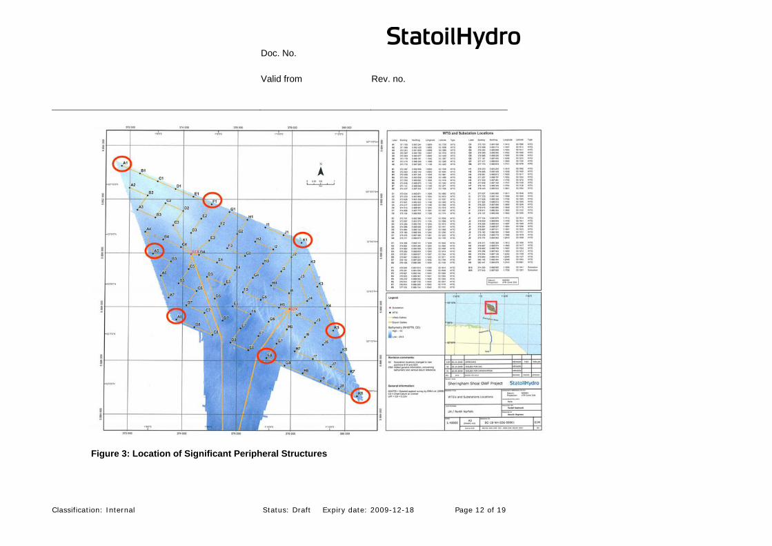
Turbine towers A1, F1, K1, K5, K8, F8, A8 and A5 (see Figure 3) to be marked as significant peripheral structures each exhibiting a Fl Y 5s light (flashing yellow every 5 seconds) about 12 metres above HAT but below the arc of the turbine blades. These aid to navigation (AtoN) lights are to be visible all round the towers to shipping, have a nominal range of 5 nautical miles and be exhibited at least at night and when the visibility reduces to 2 nautical miles or less More than one lantern will be required for each WTG, and the lanterns will need to be synchronised.
Doc. No. Valid from Rev. no.
Classification: Internal Status: Draft Expiry date: 2009-12-18 Page 12 of 19
Figure 3: Location of Significant Peripheral Structures
Doc. No. Valid from Rev. no.
Classification: Internal Status: Draft Expiry date: 2009-12-18 Page 13 of 19
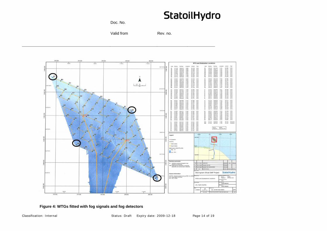
Turbine towers A1, K1, K8 and A8, see Figure 4, to be equipped with omnidirectional fog signals with an IALA Usual Range of 2 nautical miles and sounding 1 blast of 2 seconds duration every 30 seconds, to sound at least when the visibility reduces to 2 nautical miles or less. In order to minimise the fog signals, fog detectors are to be fitted to each of the WTGs equipped with fog signals.
Doc. No. Valid from Rev. no.
Classification: Internal Status: Draft Expiry date: 2009-12-18 Page 14 of 19
Figure 4: WTGs fitted with fog signals and fog detectors
Doc. No. Valid from Rev. no.
Classification: Internal Status: Draft Expiry date: 2009-12-18 Page 15 of 19
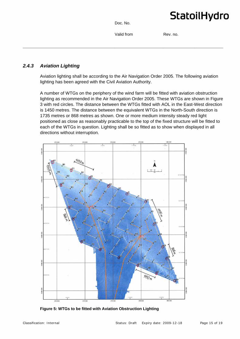
2.4.3 Aviation Lighting
Aviation lighting shall be according to the Air Navigation Order 2005. The following aviation lighting has been agreed with the Civil Aviation Authority. A number of WTGs on the periphery of the wind farm will be fitted with aviation obstruction lighting as recommended in the Air Navigation Order 2005. These WTGs are shown in Figure 3 with red circles. The distance between the WTGs fitted with AOL in the East-West direction is 1450 metres. The distance between the equivalent WTGs in the North-South direction is 1735 metres or 868 metres as shown. One or more medium intensity steady red light positioned as close as reasonably practicable to the top of the fixed structure will be fitted to each of the WTGs in question. Lighting shall be so fitted as to show when displayed in all directions without interruption.
Figure 5: WTGs to be fitted with Aviation Obstruction Lighting
Doc. No. Valid from Rev. no.
Classification: Internal Status: Draft Expiry date: 2009-12-18 Page 16 of 19
2.5 CDM Regulations
The CDM regulations apply and will be implemented also for the offshore part of the Sheringham Shoal Wind Farm Project.
3 Safety Zones
3.1 General
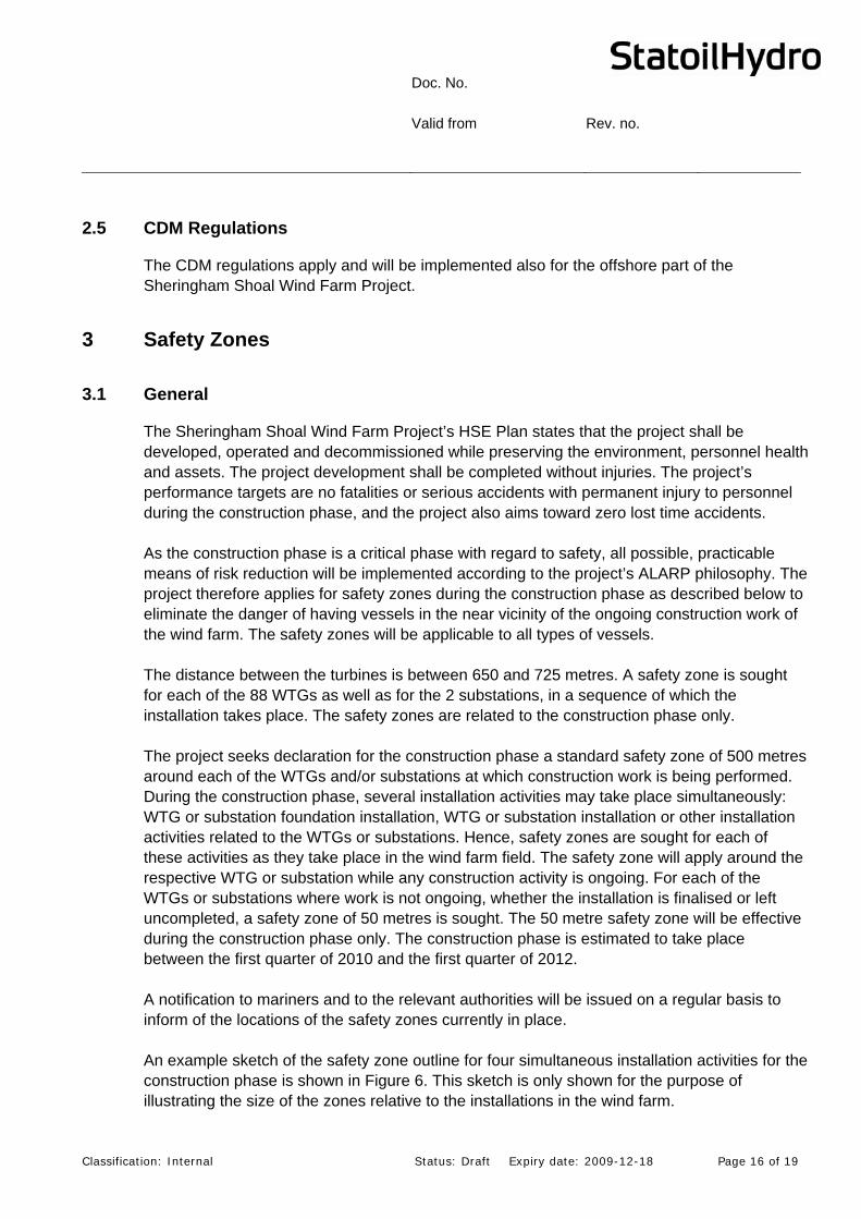
The Sheringham Shoal Wind Farm Project’s HSE Plan states that the project shall be developed, operated and decommissioned while preserving the environment, personnel health and assets. The project development shall be completed without injuries. The project’s performance targets are no fatalities or serious accidents with permanent injury to personnel during the construction phase, and the project also aims toward zero lost time accidents. As the construction phase is a critical phase with regard to safety, all possible, practicable means of risk reduction will be implemented according to the project’s ALARP philosophy. The project therefore applies for safety zones during the construction phase as described below to eliminate the danger of having vessels in the near vicinity of the ongoing construction work of the wind farm. The safety zones will be applicable to all types of vessels. The distance between the turbines is between 650 and 725 metres. A safety zone is sought for each of the 88 WTGs as well as for the 2 substations, in a sequence of which the installation takes place. The safety zones are related to the construction phase only. The project seeks declaration for the construction phase a standard safety zone of 500 metres around each of the WTGs and/or substations at which construction work is being performed. During the construction phase, several installation activities may take place simultaneously: WTG or substation foundation installation, WTG or substation installation or other installation activities related to the WTGs or substations. Hence, safety zones are sought for each of these activities as they take place in the wind farm field. The safety zone will apply around the respective WTG or substation while any construction activity is ongoing. For each of the WTGs or substations where work is not ongoing, whether the installation is finalised or left uncompleted, a safety zone of 50 metres is sought. The 50 metre safety zone will be effective during the construction phase only. The construction phase is estimated to take place between the first quarter of 2010 and the first quarter of 2012. A notification to mariners and to the relevant authorities will be issued on a regular basis to inform of the locations of the safety zones currently in place. An example sketch of the safety zone outline for four simultaneous installation activities for the construction phase is shown in Figure 6. This sketch is only shown for the purpose of illustrating the size of the zones relative to the installations in the wind farm.
Doc. No. Valid from Rev. no.
Classification: Internal Status: Draft Expiry date: 2009-12-18 Page 17 of 19
Figure 6: Safety Zone Layout
Doc. No. Valid from Rev. no.
Classification: Internal Status: Draft Expiry date: 2009-12-18 Page 18 of 19
3.2 Monitoring of Area
The marine crew on the installation vessels will monitor vessels and activities within the wind farm area. There will, however, not be allocated any designated vessel to monitor vessels and activities in the area. According to the regulations, notice of the activities on the wind farm area will be given to mariners, in the Kingfisher Bulletin and through other relevant information channels.
3.3 Traffic Survey
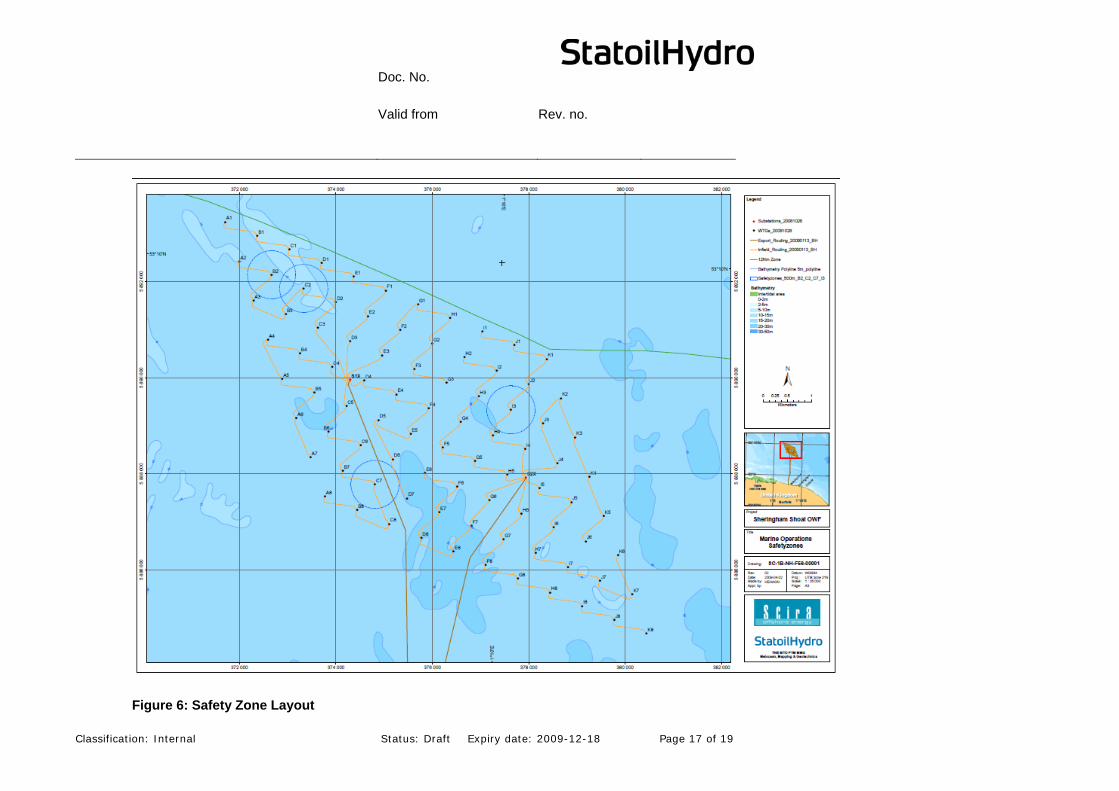
Two surveys of the ship traffic were performed in February and October 2005 by Anatec UK Ltd. The survey was carried out for 28 24-hour periods and included radar, Automatic Identification System and visual observation. The survey equipment and personnel were based at the Cromer Lighthouse. The total number of vessels tracked within 15 nm of the site was 2,346 giving an average of 84 vessels per day (based on 28 days of surveying in total). The vessel density in and around the Sheringham Shoal Wind Farm area is shown in Figure 7. Inside the Wind Farm area, the density of ships per day varied between 0 and 1.
Figure 7: Ship density map within 15 nm of site
Doc. No. Valid from Rev. no.
Classification: Internal Status: Draft Expiry date: 2009-12-18 Page 19 of 19
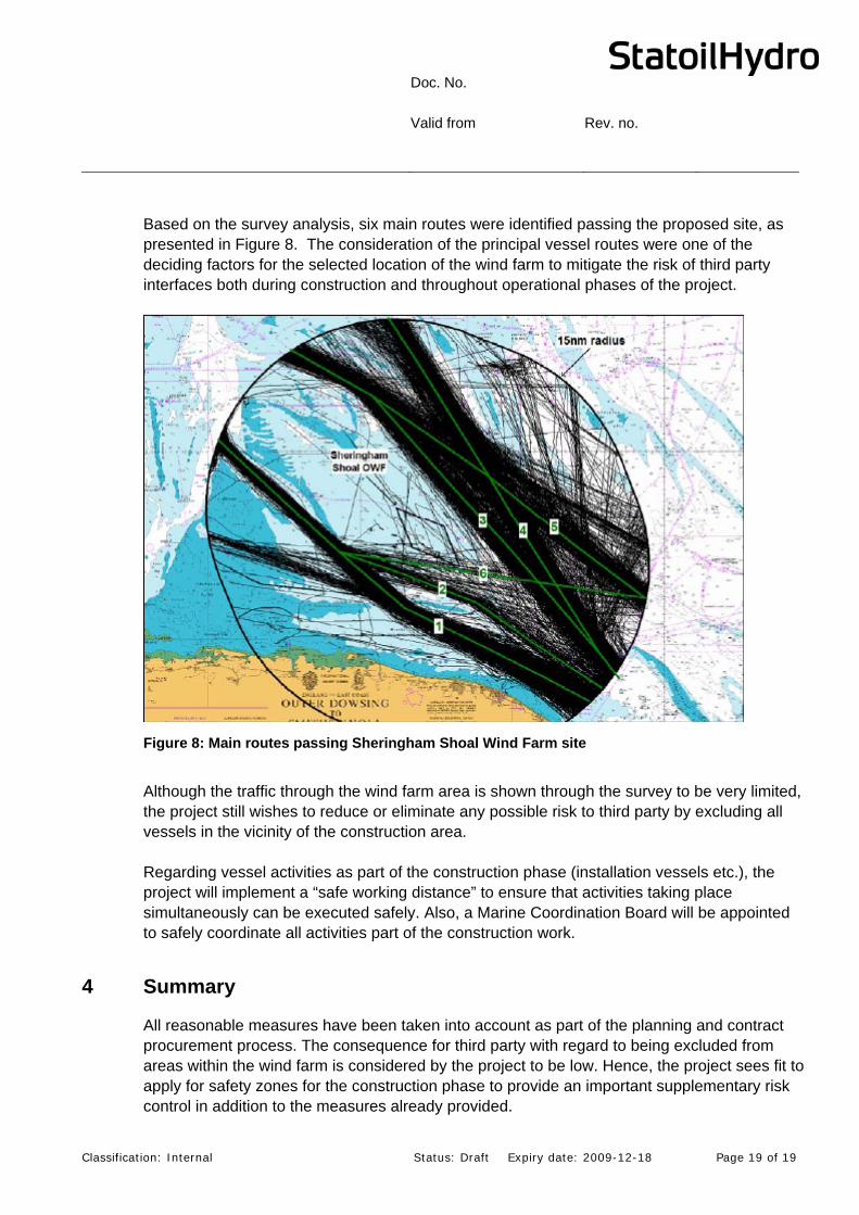
Based on the survey analysis, six main routes were identified passing the proposed site, as presented in Figure 8. The consideration of the principal vessel routes were one of the deciding factors for the selected location of the wind farm to mitigate the risk of third party interfaces both during construction and throughout operational phases of the project.
Figure 8: Main routes passing Sheringham Shoal Wind Farm site
Although the traffic through the wind farm area is shown through the survey to be very limited, the project still wishes to reduce or eliminate any possible risk to third party by excluding all vessels in the vicinity of the construction area. Regarding vessel activities as part of the construction phase (installation vessels etc.), the project will implement a “safe working distance” to ensure that activities taking place simultaneously can be executed safely. Also, a Marine Coordination Board will be appointed to safely coordinate all activities part of the construction work.
4 Summary
All reasonable measures have been taken into account as part of the planning and contract procurement process. The consequence for third party with regard to being excluded from areas within the wind farm is considered by the project to be low. Hence, the project sees fit to apply for safety zones for the construction phase to provide an important supplementary risk control in addition to the measures already provided.


![Substation Location in O shore Wind Farms { A Planar … · Wind Farm (OWF) installations: Barrow [5], Walney 1 [6] and Sheringham Shoal [7], consisting of 30, 51 and 88 turbines,](https://img.pdfslide.us/doc/110x75/5b91399309d3f28a7e8dc766/substation-location-in-o-shore-wind-farms-a-planar-wind-farm-owf-installations.jpg)