Embed Size (px)
Citation preview
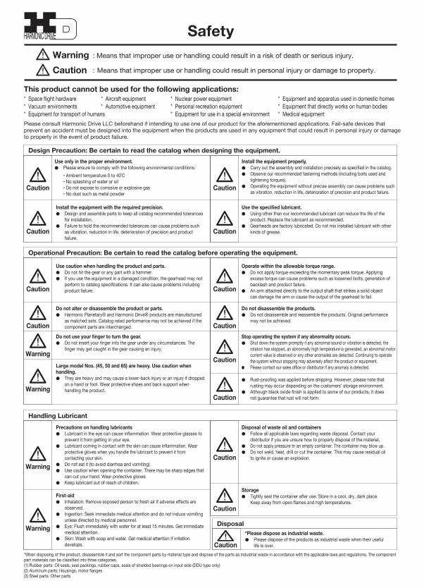
Design Precaution: Be certain to read the catalog when designing the equipment.
Operational Precaution: Be certain to read the catalog before operating the equipment.
Handling Lubricant
Disposal
Use only in the proper environment.● Please ensure to comply with the following environmental conditions:
• Ambient temperature 0 to 40˚C • No splashing of water or oil• Do not expose to corrosive or explosive gas• No dust such as metal powder
*When disposing of the product, disassemble it and sort the component parts by material type and dispose of the parts as industrial waste in accordance with the applicable laws and regulations. The component part materials can be classified into three categories.(1) Rubber parts: Oil seals, seal packings, rubber caps, seals of shielded bearings on input side (DDU type only)(2) Aluminum parts: Housings, motor flanges(3) Steel parts: Other parts
Caution
Caution
Caution
Caution
Caution Caution
Caution
Warning
Warning
Warning
Warning
Caution
Caution
Caution
Caution
Caution
Caution
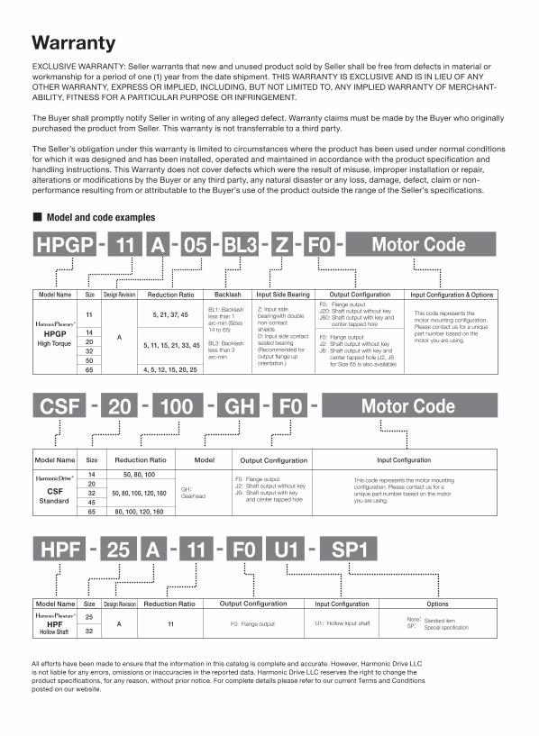
EXCLUSIVE WARRANTY: Seller warrants that new and unused product sold by Seller shall be free from defects in material or workmanship for a period of one (1) year from the date shipment. THIS WARRANTY IS EXCLUSIVE AND IS IN LIEU OF ANY OTHER WARRANTY, EXPRESS OR IMPLIED, INCLUDING, BUT NOT LIMITED TO, ANY IMPLIED WARRANTY OF MERCHANT-ABILITY, FITNESS FOR A PARTICULAR PURPOSE OR INFRINGEMENT.
The Buyer shall promptly notify Seller in writing of any alleged defect. Warranty claims must be made by the Buyer who originally purchased the product from Seller. This warranty is not transferrable to a third party.
The Seller’s obligation under this warranty is limited to circumstances where the product has been used under normal conditions for which it was designed and has been installed, operated and maintained in accordance with the product specification and handling instructions. This Warranty does not cover defects which were the result of misuse, improper installation or repair, alterations or modifications by the Buyer or any third party, any natural disaster or any loss, damage, defect, claim or non-performance resulting from or attributable to the Buyer’s use of the product outside the range of the Seller’s specifications.
All efforts have been made to ensure that the information in this catalog is complete and accurate. However, Harmonic Drive LLCis not liable for any errors, omissions or inaccuracies in the reported data. Harmonic Drive LLC reserves the right to change theproduct specifications, for any reason, without prior notice. For complete details please refer to our current Terms and Conditionsposted on our website.
Model and Code ExamplesInstall the equipment properly.● Carry out the assembly and installation precisely as specified in the catalog.● Observe our recommended fastening methods (including bolts used and
tightening torques).● Operating the equipment without precise assembly can cause problems such
as vibration, reduction in life, deterioration of precision and product failure.
Operate within the allowable torque range.● Do not apply torque exceeding the momentary peak torque. Applying
excess torque can cause problems such as loosened bolts, generation of backlash and product failure.
● An arm attached directly to the output shaft that strikes a solid object can damage the arm or cause the output of the gearhead to fail.
Do not disassemble the products.● Do not disassemble and reassemble the products. Original performance
may not be achieved.
● Rust-proofing was applied before shipping. However, please note that rusting may occur depending on the customers' storage environment.
● Although black oxide finish is applied to some of our products, it does not guarantee that rust will not form.
Stop operating the system if any abnormality occurs.● Shut down the system promptly if any abnormal sound or vibration is detected, the
rotation has stopped, an abnormally high temperature is generated, an abnormal motor current value is observed or any other anomalies are detected. Continuing to operate the system without stopping may adversely affect the product or equipment.
● Please contact our sales office or distributor if any anomaly is detected.
Use caution when handling the product and parts.● Do not hit the gear or any part with a hammer. ● If you use the equipment in a damaged condition, the gearhead may not
perform to catalog specifications. It can also cause problems including product failure.
Do not alter or disassemble the product or parts. ● Harmonic Planetary® and Harmonic Drive® products are manufactured
as matched sets. Catalog rated performance may not be achieved if the component parts are interchanged.
Do not use your finger to turn the gear.● Do not insert your finger into the gear under any circumstances. The
finger may get caught in the gear causing an injury.
Large model Nos. (45, 50 and 65) are heavy. Use caution when handling.● They are heavy and may cause a lower-back injury or an injury if dropped
on a hand or foot. Wear protective shoes and back support when handling the product.
Disposal of waste oil and containers● Follow all applicable laws regarding waste disposal. Contact your
distributor if you are unsure how to properly dispose of the material. ● Do not apply pressure tn an empty container. The container may blow up.● Do not weld, heat, drill or cut the container. This may cause residual oil
to ignite or cause an explosion.
Storage● Tightly seal the container after use. Store in a cool, dry, dark place.
Keep away from open flames and high temperatures.
Precautions on handling lubricants● Lubricant in the eye can cause inflammation. Wear protective glasses to
prevent it from getting in your eye. ● Lubricant coming in contact with the skin can cause inflammation. Wear
protective gloves when you handle the lubricant to prevent it from contacting your skin.
● Do not eat it (to avoid diarrhea and vomiting).● Use caution when opening the container. There may be sharp edges that
can cut your hand. Wear protective gloves.● Keep lubricant out of reach of children.
First-aid● Inhalation: Remove exposed person to fresh air if adverse effects are
observed. ● Ingestion: Seek immediate medical attention and do not induce vomiting
unless directed by medical personnel. ● Eye: Flush immediately with water for at least 15 minutes. Get immediate
medical attention. ● Skin: Wash with soap and water. Get medical attention if irritation
develops.
*Please dispose as industrial waste.● Please dispose of the products as industrial waste when their useful
life is over.
SafetyWarningCaution
: Means that improper use or handling could result in a risk of death or serious injury.
: Means that improper use or handling could result in personal injury or damage to property.
* Space flight hardware * Aircraft equipment * Nuclear power equipment * Equipment and apparatus used in domestic homes* Vacuum environments * Automotive equipment * Personal recreation equipment * Equipment that directly works on human bodies * Equipment for transport of humans * Equipment for use in a special environment * Medical equipmentPlease consult Harmonic Drive LLC beforehand if intending to use one of our product for the aforementioned applications. Fail-safe devices that prevent an accident must be designed into the equipment when the products are used in any equipment that could result in personal injury or damage to property in the event of product failure.
This product cannot be used for the following applications:
Use the specified lubricant.● Using other than our recommended lubricant can reduce the life of the
product. Replace the lubricant as recommended.● Gearheads are factory lubricated. Do not mix installed lubricant with other
kinds of grease.
Install the equipment with the required precision.● Design and assemble parts to keep all catalog recommended tolerances
for installation.● Failure to hold the recommended tolerances can cause problems such
as vibration, reduction in life, deterioration of precision and product failure.
Warranty
HPGP 11 A 05 F0 XXXX SP1----
HPGP A
5, 21, 37, 45
5, 11, 15, 21, 33, 45
4, 5, 12, 15, 20, 25
Reduction Ratio Input Configuration Special Specification
11
1420325065
High Torque
This code represents the motor mounting configuration. This code differs depending on the motor to be used. Please contact the Sales Division for the mounting codes of motors not listed in the matching tables
F0: Flange outputJ2: Straight shaft (without key)J6: Straight shaft (with key and center
tap) (J2, J6 for Size 65 is a custom specification)
F0: Flange outputJ20: Straight shaft (without key)J60: Straight shaft (with key and
center tap)
None:SP:
Standard itemSpecial specification
BL1: Backlash less than 1 arc-min, custom specification. (Sizes 14 to 65)
D: Input side contact sealed bearing (DDU)NR6: Noise reduction, backlash less than 6
arc-min
Model Name Size Design Revision Output Configuration
CSF
Reduction RatioSizeModel Name
CSF
Model Input Configuration Special Specification
1420324565
50, 80, 100
50, 80, 100, 120, 160
80, 100, 120, 160
GH:Gearhead
20 100 GH F0 XXX SP1- - - - -
Standard
This code represents the motor mounting configuration. This code differs depending on the motor to be used. Please contact the Sales Division for the mounting codes of motors not listed in the matching tables
F0: Flange outputJ2: Straight shaft (without
key)J6: Straight shaft (with key
and center tap)
None:SP:
Standard itemSpecial specification
Output Configuration
HPF A 1125
32U1: Hollow input shaftF0: Flange output
Hollow Shaft
HPF 25 A 11 F0 SP1U1 ----
Model Name Size Reduction Ratio Input Configuration Special Specification
None:SP:
Standard itemSpecial specification
Design Revision Output Configuration
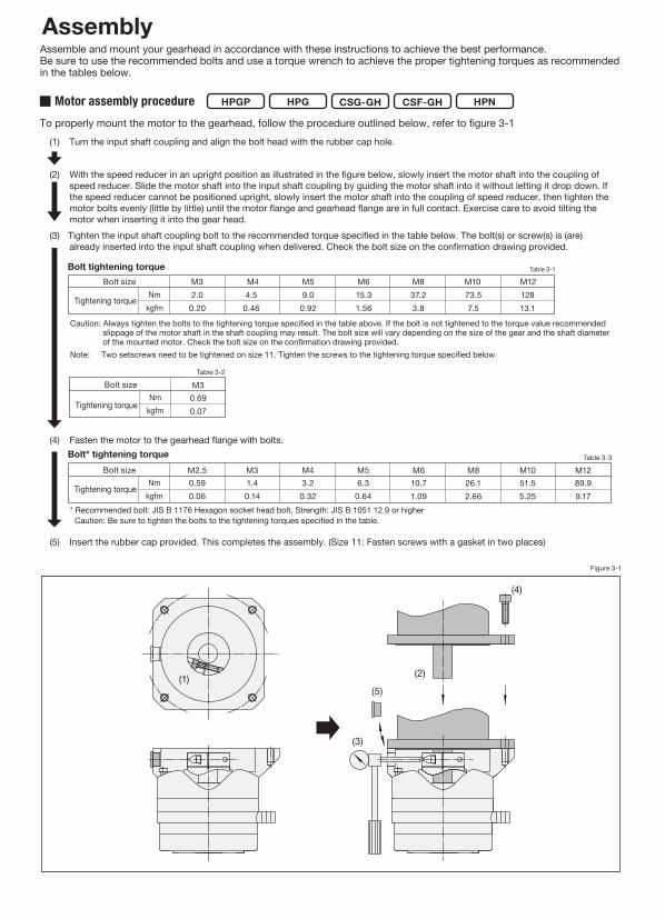
Assemble and mount your gearhead in accordance with these instructions to achieve the best performance.Be sure to use the recommended bolts and use a torque wrench to achieve the proper tightening torques as recommended in the tables below.
To properly mount the motor to the gearhead, follow the procedure outlined below, refer to figure 3-1
Assembly
(1) (2)(3)
(4)
(5)
(6)
(2) For HPG/HPGP/HPN series, apply a sealant to the surface of the motor flange that will contact the gearhead mounting flange. (Recommended sealant: LOCTITE 515)
Bolt* tightening torque
* Recommended bolt: JIS B 1176 Hexagon socket head bolt, Strength: JIS B 1051 12.9 or higher Caution: Be sure to tighten the bolts to the tightening torques specified in the table.
(1) Turn the input shaft coupling and align the bolt head with the rubber cap hole.
(4) Fasten the motor to the gearhead flange with bolts.
Bolt tightening torque
(5) Tighten the input shaft coupling bolt to the recommended torque specified in the table below. The bolt(s) or screw(s) is (are) already inserted into the input shaft coupling when delivered. Check the bolt size on the confirmation drawing provided.
(6) Insert the rubber cap provided. This completes the assembly. (Size 11: Fasten screws with a gasket in two places)
(3) With the speed reducer in an upright position as illustrated in the figure below, slowly insert the motor shaft into the coupling of speed reducer. Slide the motor shaft into the input shaft coupling by guiding the motor shaft into it without letting it drop down. If the speed reducer cannot be positioned upright, slowly insert the motor shaft into the coupling of speed reducer, then tighten the motor bolts evenly (little by little) until the motor flange and gearhead flange are in full contact. Exercise care to avoid tilting the motor when inserting it into the gear head.
Caution: Always tighten the bolts to the tightening torque specified in the table above. If the bolt is not tightened to the torque value recommended slippage of the motor shaft in the shaft coupling may result. The bolt size will vary depending on the size of the gear and the shaft diameter of the mounted motor. Check the bolt size on the confirmation drawing provided.
Note: Two setscrews need to be tightened on size 11. Tighten the screws to the tightening torque specified below.
HPG CSG-GH CSF-GHHPGP HPNMotor assembly procedure
Table 3-1
Table 3-2
Table 3-3
Bolt size
Tightening torque
Bolt size
Tightening torque
M3 M4 M5 M6 M8 M10 M12
M3 M4 M5 M6 M8 M10 M12
M2.5Nm
kgfm
2.00.20
4.50.46
9.00.92
15.31.56
37.23.8
73.57.5
12813.1
Nmkgfm
1.40.14
3.20.32
6.30.64
10.71.09
26.12.66
51.55.25
89.99.17
0.590.06
Tightening torque
M30.690.07
Nmkgfm
Bolt size
Figure 3-1
Table 4-1
Table 4-2
Figure 4-1
Part B
Part A
Some right angle gearhead models weigh as much as 130 lbs (60 kg). No thread for an eyebolt is provided because the mounting orientation varies depending on the customer's need. When mounting the reducer, hoist it using a sling paying extreme attention to safety.When assembling gearheads into your equipment, check the flatness of your mounting surface and look for any burrs on tapped holes. Then fasten the flange (Part A in the diagram below) using appropriate bolts.
* Recommended bolts: JIS B 1176 "Hexagon socket head bolts." Strength classification 12.9 or higher in JIS B 1051.
* Recommended bolts: JIS B 1176 "Hexagon socket head bolts." Strength classification 12.9 or higher in JIS B 1051.
Bolt* tightening torque for output flange (Part B in the Figure 4-1)
Output flange mounting specifications
HPG HPFCSG-GH CSF-GHHPGP HPN
HPGP
Bolt* tightening torque for flange (Part A in the diagram below)
655032201411Size4
M4184.5
0.4625.32.58
8M4304.5
0.46848.6
8M645
15.31.5628629.2
8M860
37.23.869771.2
8M1290
128.413.12407245
8M1612031932.55972609
mmNm
kgfmNm
kgfm
Table 4-3
* Recommended bolts: JIS B 1176 "Hexagon socket head bolts." Strength classification 12.9 or higher in JIS B 1051.
Bolt* tightening torque for output flange (Part B in the Figure 4-1) HPG
655032201411Size3
M4184.5
0.4619.01.9
6M4304.5
0.46636.5
6M645
15.31.5621521.9
6M860
37.23.852453.4
14M810037.23.802036207.8
6M1612031932.54480457
mmNm
kgfmNm
kgfm
Speed reducer assembly
Mounting the load to the output flangeFollow the specifications in the table below when mounting the load onto the output flange.
Number of boltsBolt sizeMounting PCD
Tightening torque
Transmission torque
Number of boltsBolt sizeMounting PCD
Tightening torque
Transmission torque
4M1626025526.05180528
12M41274.5
0.4653154.2
12M51579.0
0.921060108
4M1219010310.52030207
4M1013551.55.2586888.6
4M810526.12.6642843.6
4M5706.3
0.6411011.3
4M3461.40.1426.32.69
4M3501.40.1427.92.85
11 14 20114
M5706.3
0.6411011.3
4M610010.71.0922322.8
4M813026.12.6652853.9
14 20 324
M1016551.55.261063108.5
40 32HPGP / HPG / CSG-GH / CSF-GHHPN HPF
45/50 65 25 32Number of boltsBolt sizeMounting PCD
Size
mmNm
kgfmNm
kgfm
Tightening torque
Transfer torque
Design Precaution: Be certain to read the catalog when designing the equipment.
Operational Precaution: Be certain to read the catalog before operating the equipment.
Handling Lubricant
Disposal
Use only in the proper environment.● Please ensure to comply with the following environmental conditions:
• Ambient temperature 0 to 40˚C• No splashing of water or oil• Do not expose to corrosive or explosive gas• No dust such as metal powder
*When disposing of the product, disassemble it and sort the component parts by material type and dispose of the parts as industrial waste in accordance with the applicable laws and regulations. The component part materials can be classified into three categories.(1) Rubber parts: Oil seals, seal packings, rubber caps, seals of shielded bearings on input side (DDU type only)(2) Aluminum parts: Housings, motor flanges(3) Steel parts: Other parts
Caution
Caution
Caution
Caution
Caution Caution
Caution
Warning
Warning
Warning
Warning
Caution
Caution
Caution
Caution
Caution
Caution
EXCLUSIVE WARRANTY: Seller warrants that new and unused product sold by Seller shall be free from defects in material or workmanship for a period of one (1) year from the date shipment. THIS WARRANTY IS EXCLUSIVE AND IS IN LIEU OF ANY OTHER WARRANTY, EXPRESS OR IMPLIED, INCLUDING, BUT NOT LIMITED TO, ANY IMPLIED WARRANTY OF MERCHANT-ABILITY, FITNESS FOR A PARTICULAR PURPOSE OR INFRINGEMENT.
The Buyer shall promptly notify Seller in writing of any alleged defect. Warranty claims must be made by the Buyer who originally purchased the product from Seller. This warranty is not transferrable to a third party.
The Seller’s obligation under this warranty is limited to circumstances where the product has been used under normal conditions for which it was designed and has been installed, operated and maintained in accordance with the product specification and handling instructions. This Warranty does not cover defects which were the result of misuse, improper installation or repair, alterations or modifications by the Buyer or any third party, any natural disaster or any loss, damage, defect, claim or non-performance resulting from or attributable to the Buyer’s use of the product outside the range of the Seller’s specifications.
All efforts have been made to ensure that the information in this catalog is complete and accurate. However, Harmonic Drive LLCis not liable for any errors, omissions or inaccuracies in the reported data. Harmonic Drive LLC reserves the right to change theproduct specifications, for any reason, without prior notice. For complete details please refer to our current Terms and Conditionsposted on our website.
Model and code examplesInstall the equipment properly.● Carry out the assembly and installation precisely as specified in the catalog.● Observe our recommended fastening methods (including bolts used and
tightening torques).● Operating the equipment without precise assembly can cause problems such
as vibration, reduction in life, deterioration of precision and product failure.
Operate within the allowable torque range.● Do not apply torque exceeding the momentary peak torque. Applying
excess torque can cause problems such as loosened bolts, generation of backlash and product failure.
● An arm attached directly to the output shaft that strikes a solid object can damage the arm or cause the output of the gearhead to fail.
Do not disassemble the products.● Do not disassemble and reassemble the products. Original performance
may not be achieved.
● Rust-proofing was applied before shipping. However, please note that rusting may occur depending on the customers' storage environment.
● Although black oxide finish is applied to some of our products, it does not guarantee that rust will not form.
Stop operating the system if any abnormality occurs.● Shut down the system promptly if any abnormal sound or vibration is detected, the
rotation has stopped, an abnormally high temperature is generated, an abnormal motor current value is observed or any other anomalies are detected. Continuing to operate the system without stopping may adversely affect the product or equipment.
● Please contact our sales office or distributor if any anomaly is detected.
Use caution when handling the product and parts.● Do not hit the gear or any part with a hammer. ● If you use the equipment in a damaged condition, the gearhead may not
perform to catalog specifications. It can also cause problems including product failure.
Do not alter or disassemble the product or parts. ● Harmonic Planetary® and Harmonic Drive® products are manufactured
as matched sets. Catalog rated performance may not be achieved if the component parts are interchanged.
Do not use your finger to turn the gear.● Do not insert your finger into the gear under any circumstances. The
finger may get caught in the gear causing an injury.
Large model Nos. (45, 50 and 65) are heavy. Use caution when handling.● They are heavy and may cause a lower-back injury or an injury if dropped
on a hand or foot. Wear protective shoes and back support when handling the product.
Disposal of waste oil and containers● Follow all applicable laws regarding waste disposal. Contact your
distributor if you are unsure how to properly dispose of the material. ● Do not apply pressure tn an empty container. The container may blow up.● Do not weld, heat, drill or cut the container. This may cause residual oil
to ignite or cause an explosion.
Storage● Tightly seal the container after use. Store in a cool, dry, dark place.
Keep away from open flames and high temperatures.
Precautions on handling lubricants● Lubricant in the eye can cause inflammation. Wear protective glasses to
prevent it from getting in your eye. ● Lubricant coming in contact with the skin can cause inflammation. Wear
protective gloves when you handle the lubricant to prevent it from contacting your skin.
● Do not eat it (to avoid diarrhea and vomiting).● Use caution when opening the container. There may be sharp edges that
can cut your hand. Wear protective gloves.● Keep lubricant out of reach of children.
First-aid● Inhalation: Remove exposed person to fresh air if adverse effects are
observed. ● Ingestion: Seek immediate medical attention and do not induce vomiting
unless directed by medical personnel. ● Eye: Flush immediately with water for at least 15 minutes. Get immediate
medical attention. ● Skin: Wash with soap and water. Get medical attention if irritation
develops.
*Please dispose as industrial waste.● Please dispose of the products as industrial waste when their useful
life is over.
SafetyWarningCaution
: Means that improper use or handling could result in a risk of death or serious injury.
: Means that improper use or handling could result in personal injury or damage to property.
* Space flight hardware * Aircraft equipment * Nuclear power equipment * Equipment and apparatus used in domestic homes* Vacuum environments * Automotive equipment * Personal recreation equipment * Equipment that directly works on human bodies* Equipment for transport of humans * Equipment for use in a special environment * Medical equipmentPlease consult Harmonic Drive LLC beforehand if intending to use one of our product for the aforementioned applications. Fail-safe devices that prevent an accident must be designed into the equipment when the products are used in any equipment that could result in personal injury or damage to property in the event of product failure.
This product cannot be used for the following applications:
Use the specified lubricant.● Using other than our recommended lubricant can reduce the life of the
product. Replace the lubricant as recommended.● Gearheads are factory lubricated. Do not mix installed lubricant with other
kinds of grease.
Install the equipment with the required precision.● Design and assemble parts to keep all catalog recommended tolerances
for installation.● Failure to hold the recommended tolerances can cause problems such
as vibration, reduction in life, deterioration of precision and product failure.
Warranty
Assemble and mount your gearhead in accordance with these instructions to achieve the best performance.Be sure to use the recommended bolts and use a torque wrench to achieve the proper tightening torques as recommended in the tables below.
To properly mount the motor to the gearhead, follow the procedure outlined below, refer to figure 3-1
Assembly
(1) (2)(3)
(5)
(4)
(6)
(1) Turn the input shaft coupling and align the bolt head with the rubber cap hole.
Bolt tightening torque
(3) Tighten the input shaft coupling bolt to the recommended torque specified in the table below. The bolt(s) or screw(s) is (are) already inserted into the input shaft coupling when delivered. Check the bolt size on the confirmation drawing provided.
(5) Insert the rubber cap provided. This completes the assembly. (Size 11: Fasten screws with a gasket in two places)
(2) With the speed reducer in an upright position as illustrated in the figure below, slowly insert the motor shaft into the coupling of speed reducer. Slide the motor shaft into the input shaft coupling by guiding the motor shaft into it without letting it drop down. If the speed reducer cannot be positioned upright, slowly insert the motor shaft into the coupling of speed reducer, then tighten the motor bolts evenly (little by little) until the motor flange and gearhead flange are in full contact. Exercise care to avoid tilting the motor when inserting it into the gear head.
Caution: Always tighten the bolts to the tightening torque specified in the table above. If the bolt is not tightened to the torque value recommended slippage of the motor shaft in the shaft coupling may result. The bolt size will vary depending on the size of the gear and the shaft diameter of the mounted motor. Check the bolt size on the confirmation drawing provided.
Note: Two setscrews need to be tightened on size 11. Tighten the screws to the tightening torque specified below.
HPG CSG-GH CSF-GHHPGP HPNMotor assembly procedure
Table 3-1
Table 3-2
Bolt size
Tightening torque
M3 M4 M5 M6 M8 M10 M122.0
0.204.5
0.469.0
0.9215.31.56
37.23.8
73.57.5
12813.1
Nmkgfm
Bolt* tightening torque
* Recommended bolt: JIS B 1176 Hexagon socket head bolt, Strength: JIS B 1051 12.9 or higherCaution: Be sure to tighten the bolts to the tightening torques specified in the table.
(4) Fasten the motor to the gearhead flange with bolts.Table 3-3
Bolt size
Tightening torque
M3 M4 M5 M6 M8 M10 M12M2.5Nm
kgfm1.40.14
3.20.32
6.30.64
10.71.09
26.12.66
51.55.25
89.99.17
0.590.06
Tightening torque
M30.690.07
Nmkgfm
Bolt size
Figure 3-1
Table 4-1
Table 4-2
Figure 4-1
Part B
Part A
Some right angle gearhead models weigh as much as 130 lbs (60 kg). No thread for an eyebolt is provided because the mounting orientation varies depending on the customer's need. When mounting the reducer, hoist it using a sling paying extreme attention to safety.When assembling gearheads into your equipment, check the flatness of your mounting surface and look for any burrs on tapped holes. Then fasten the flange (Part A in the diagram below) using appropriate bolts.
* Recommended bolts: JIS B 1176 "Hexagon socket head bolts." Strength classification 12.9 or higher in JIS B 1051.
Bolt* tightening torque for output flange (Part B in the Figure 4-1)
Output flange mounting specifications
HPG HPFCSG-GH CSF-GHHPGP HPN
HPGP
Bolt* tightening torque for flange (Part A in the diagram below)
655032201411Size4
M4184.5
0.4625.32.58
8M4304.5
0.46848.6
8M645
15.31.5628629.2
8M860
37.23.869771.2
8M1290
128.413.12407245
8M1612031932.55972609
mmNm
kgfmNm
kgfm
Table 4-3
* Recommended bolts: JIS B 1176 "Hexagon socket head bolts." Strength classification 12.9 or higher in JIS B 1051.
Bolt* tightening torque for output flange (Part B in the Figure 4-1) HPG
655032201411Size3
M4184.5
0.4619.01.9
6M4304.5
0.46636.5
6M645
15.31.5621521.9
6M860
37.23.852453.4
14M810037.23.802036207.8
6M1612031932.54480457
mmNm
kgfmNm
kgfm
Speed reducer assembly
Mounting the load to the output flangeFollow the specifications in the table below when mounting the load onto the output flange.
Number of boltsBolt sizeMounting PCD
Tightening torque
Transmission torque
Number of boltsBolt sizeMounting PCD
Tightening torque
Transmission torque
4M1626025526.05180528
12M41274.5
0.4653154.2
12M51579.0
0.921060108
4M1219010310.52030207
4M1013551.55.2586888.6
4M810526.12.6642843.6
4M5706.3
0.6411011.3
4M3461.40.1426.32.69
4M3501.40.1427.92.85
11 14 20114
M5706.3
0.6411011.3
4M610010.71.0922322.8
4M813026.12.6652853.9
14 20 324
M1016551.55.261063108.5
40 32HPGP / HPG / CSG-GH / CSF-GHHPN HPF
45/50 65 25 32Number of boltsBolt sizeMounting PCD
Size
mmNm
kgfmNm
kgfm
Tightening torque
Transfer torque
HPGP 11 A 05 BL3 F0Z -- ----
HPGP A
5, 21, 37, 45
5, 11, 15, 21, 33, 45
4, 5, 12, 15, 20, 25
Reduction Ratio Input Configuration & Options
11
1420325065
High Torque
This code represents the motor mounting configuration. Please contact us for a unique part number based on the motor you are using.
Z: Input sidebearingwith doublenon-contactshieldsD: Input side contactsealed bearing(Recommended foroutput flange uporientation.)
BL1: Backlash less than 1 arc-min (Sizes 14 to 65)
BL3: Backlash less than 3 arc-min
F0: Flange outputJ2: Shaft output without keyJ6: Shaft output with key and
center tapped hole (J2, J6 for Size 65 is also available)
F0: Flange outputJ20: Shaft output without keyJ60: Shaft output with key and
center tapped hole
Model Name Size Design Revision Output ConfigurationInput Side BearingBacklash
CSF
Reduction RatioSizeModel Name
CSF
Model Input Configuration
1420324565
50, 80, 100
50, 80, 100, 120, 160
80, 100, 120, 160
GH:Gearhead
20 100 GH F0- - - - -
Standard
F0: Flange outputJ2: Shaft output without keyJ6: Shaft output with key
and center tapped hole
Output Configuration
This code represents the motor mounting configuration. Please contact us for a unique part number based on the motor you are using.
Motor Code
Motor Code
HPF A 1125
32U1: Hollow input shaftF0: Flange output
Hollow Shaft
HPF 25 A 11 F0 SP1U1 ----
Model Name Size Reduction Ratio Input Configuration Options
None:SP:
Standard itemSpecial specification
Design Revision Output Configuration
Design Precaution: Be certain to read the catalog when designing the equipment.
Operational Precaution: Be certain to read the catalog before operating the equipment.
Handling Lubricant
Disposal
Use only in the proper environment.● Please ensure to comply with the following environmental conditions:
• Ambient temperature 0 to 40˚C• No splashing of water or oil• Do not expose to corrosive or explosive gas• No dust such as metal powder
*When disposing of the product, disassemble it and sort the component parts by material type and dispose of the parts as industrial waste in accordance with the applicable laws and regulations. The component part materials can be classified into three categories.(1) Rubber parts: Oil seals, seal packings, rubber caps, seals of shielded bearings on input side (DDU type only)(2) Aluminum parts: Housings, motor flanges(3) Steel parts: Other parts
Caution
Caution
Caution
Caution
Caution Caution
Caution
Warning
Warning
Warning
Warning
Caution
Caution
Caution
Caution
Caution
Caution
EXCLUSIVE WARRANTY: Seller warrants that new and unused product sold by Seller shall be free from defects in material or workmanship for a period of one (1) year from the date shipment. THIS WARRANTY IS EXCLUSIVE AND IS IN LIEU OF ANY OTHER WARRANTY, EXPRESS OR IMPLIED, INCLUDING, BUT NOT LIMITED TO, ANY IMPLIED WARRANTY OF MERCHANT-ABILITY, FITNESS FOR A PARTICULAR PURPOSE OR INFRINGEMENT.
The Buyer shall promptly notify Seller in writing of any alleged defect. Warranty claims must be made by the Buyer who originally purchased the product from Seller. This warranty is not transferrable to a third party.
The Seller’s obligation under this warranty is limited to circumstances where the product has been used under normal conditions for which it was designed and has been installed, operated and maintained in accordance with the product specification and handling instructions. This Warranty does not cover defects which were the result of misuse, improper installation or repair, alterations or modifications by the Buyer or any third party, any natural disaster or any loss, damage, defect, claim or non-performance resulting from or attributable to the Buyer’s use of the product outside the range of the Seller’s specifications.
All efforts have been made to ensure that the information in this catalog is complete and accurate. However, Harmonic Drive LLCis not liable for any errors, omissions or inaccuracies in the reported data. Harmonic Drive LLC reserves the right to change theproduct specifications, for any reason, without prior notice. For complete details please refer to our current Terms and Conditionsposted on our website.
Model and code examplesInstall the equipment properly.● Carry out the assembly and installation precisely as specified in the catalog.● Observe our recommended fastening methods (including bolts used and
tightening torques).● Operating the equipment without precise assembly can cause problems such
as vibration, reduction in life, deterioration of precision and product failure.
Operate within the allowable torque range.● Do not apply torque exceeding the momentary peak torque. Applying
excess torque can cause problems such as loosened bolts, generation of backlash and product failure.
● An arm attached directly to the output shaft that strikes a solid object can damage the arm or cause the output of the gearhead to fail.
Do not disassemble the products.● Do not disassemble and reassemble the products. Original performance
may not be achieved.
● Rust-proofing was applied before shipping. However, please note that rusting may occur depending on the customers' storage environment.
● Although black oxide finish is applied to some of our products, it does not guarantee that rust will not form.
Stop operating the system if any abnormality occurs.● Shut down the system promptly if any abnormal sound or vibration is detected, the
rotation has stopped, an abnormally high temperature is generated, an abnormal motor current value is observed or any other anomalies are detected. Continuing to operate the system without stopping may adversely affect the product or equipment.
● Please contact our sales office or distributor if any anomaly is detected.
Use caution when handling the product and parts.● Do not hit the gear or any part with a hammer. ● If you use the equipment in a damaged condition, the gearhead may not
perform to catalog specifications. It can also cause problems including product failure.
Do not alter or disassemble the product or parts. ● Harmonic Planetary® and Harmonic Drive® products are manufactured
as matched sets. Catalog rated performance may not be achieved if the component parts are interchanged.
Do not use your finger to turn the gear.● Do not insert your finger into the gear under any circumstances. The
finger may get caught in the gear causing an injury.
Large model Nos. (45, 50 and 65) are heavy. Use caution when handling.● They are heavy and may cause a lower-back injury or an injury if dropped
on a hand or foot. Wear protective shoes and back support when handling the product.
Disposal of waste oil and containers● Follow all applicable laws regarding waste disposal. Contact your
distributor if you are unsure how to properly dispose of the material. ● Do not apply pressure tn an empty container. The container may blow up.● Do not weld, heat, drill or cut the container. This may cause residual oil
to ignite or cause an explosion.
Storage● Tightly seal the container after use. Store in a cool, dry, dark place.
Keep away from open flames and high temperatures.
Precautions on handling lubricants● Lubricant in the eye can cause inflammation. Wear protective glasses to
prevent it from getting in your eye. ● Lubricant coming in contact with the skin can cause inflammation. Wear
protective gloves when you handle the lubricant to prevent it from contacting your skin.
● Do not eat it (to avoid diarrhea and vomiting).● Use caution when opening the container. There may be sharp edges that
can cut your hand. Wear protective gloves.● Keep lubricant out of reach of children.
First-aid● Inhalation: Remove exposed person to fresh air if adverse effects are
observed. ● Ingestion: Seek immediate medical attention and do not induce vomiting
unless directed by medical personnel. ● Eye: Flush immediately with water for at least 15 minutes. Get immediate
medical attention. ● Skin: Wash with soap and water. Get medical attention if irritation
develops.
*Please dispose as industrial waste.● Please dispose of the products as industrial waste when their useful
life is over.
SafetyWarningCaution
: Means that improper use or handling could result in a risk of death or serious injury.
: Means that improper use or handling could result in personal injury or damage to property.
* Space flight hardware * Aircraft equipment * Nuclear power equipment * Equipment and apparatus used in domestic homes* Vacuum environments * Automotive equipment * Personal recreation equipment * Equipment that directly works on human bodies* Equipment for transport of humans * Equipment for use in a special environment * Medical equipmentPlease consult Harmonic Drive LLC beforehand if intending to use one of our product for the aforementioned applications. Fail-safe devices that prevent an accident must be designed into the equipment when the products are used in any equipment that could result in personal injury or damage to property in the event of product failure.
This product cannot be used for the following applications:
Use the specified lubricant.● Using other than our recommended lubricant can reduce the life of the
product. Replace the lubricant as recommended.● Gearheads are factory lubricated. Do not mix installed lubricant with other
kinds of grease.
Install the equipment with the required precision.● Design and assemble parts to keep all catalog recommended tolerances
for installation.● Failure to hold the recommended tolerances can cause problems such
as vibration, reduction in life, deterioration of precision and product failure.
Warranty
Assemble and mount your gearhead in accordance with these instructions to achieve the best performance.Be sure to use the recommended bolts and use a torque wrench to achieve the proper tightening torques as recommended in the tables below.
To properly mount the motor to the gearhead, follow the procedure outlined below, refer to figure 3-1
Assembly
(1) (2)
(4)
(3)
(5)
(1) Turn the input shaft coupling and align the bolt head with the rubber cap hole.
Bolt tightening torque
(3) Tighten the input shaft coupling bolt to the recommended torque specified in the table below. The bolt(s) or screw(s) is (are) already inserted into the input shaft coupling when delivered. Check the bolt size on the confirmation drawing provided.
(5) Insert the rubber cap provided. This completes the assembly. (Size 11: Fasten screws with a gasket in two places)
(2) With the speed reducer in an upright position as illustrated in the figure below, slowly insert the motor shaft into the coupling of speed reducer. Slide the motor shaft into the input shaft coupling by guiding the motor shaft into it without letting it drop down. If the speed reducer cannot be positioned upright, slowly insert the motor shaft into the coupling of speed reducer, then tighten the motor bolts evenly (little by little) until the motor flange and gearhead flange are in full contact. Exercise care to avoid tilting the motor when inserting it into the gear head.
Caution: Always tighten the bolts to the tightening torque specified in the table above. If the bolt is not tightened to the torque value recommended slippage of the motor shaft in the shaft coupling may result. The bolt size will vary depending on the size of the gear and the shaft diameter of the mounted motor. Check the bolt size on the confirmation drawing provided.
Note: Two setscrews need to be tightened on size 11. Tighten the screws to the tightening torque specified below.
HPG CSG-GH CSF-GHHPGP HPNMotor assembly procedure
Table 3-1
Table 3-2
Bolt size
Tightening torque
M3 M4 M5 M6 M8 M10 M122.0
0.204.5
0.469.0
0.9215.31.56
37.23.8
73.57.5
12813.1
Nmkgfm
Bolt* tightening torque
* Recommended bolt: JIS B 1176 Hexagon socket head bolt, Strength: JIS B 1051 12.9 or higherCaution: Be sure to tighten the bolts to the tightening torques specified in the table.
(4) Fasten the motor to the gearhead flange with bolts.Table 3-3
Bolt size
Tightening torque
M3 M4 M5 M6 M8 M10 M12M2.5Nm
kgfm1.40.14
3.20.32
6.30.64
10.71.09
26.12.66
51.55.25
89.99.17
0.590.06
Tightening torque
M30.690.07
Nmkgfm
Bolt size
Figure 3-1
Table 4-1
Table 4-2
Figure 4-1
Part B
Part A
Some right angle gearhead models weigh as much as 130 lbs (60 kg). No thread for an eyebolt is provided because the mounting orientation varies depending on the customer's need. When mounting the reducer, hoist it using a sling paying extreme attention to safety.When assembling gearheads into your equipment, check the flatness of your mounting surface and look for any burrs on tapped holes. Then fasten the flange (Part A in the diagram below) using appropriate bolts.
* Recommended bolts: JIS B 1176 "Hexagon socket head bolts." Strength classification 12.9 or higher in JIS B 1051.
Bolt* tightening torque for output flange (Part B in the Figure 4-1)
Output flange mounting specifications
HPG HPFCSG-GH CSF-GHHPGP HPN
HPGP
Bolt* tightening torque for flange (Part A in the diagram below)
655032201411Size4
M4184.5
0.4625.32.58
8M4304.5
0.46848.6
8M645
15.31.5628629.2
8M860
37.23.869771.2
8M1290
128.413.12407245
8M1612031932.55972609
mmNm
kgfmNm
kgfm
Table 4-3
* Recommended bolts: JIS B 1176 "Hexagon socket head bolts." Strength classification 12.9 or higher in JIS B 1051.
Bolt* tightening torque for output flange (Part B in the Figure 4-1) HPG
655032201411Size3
M4184.5
0.4619.01.9
6M4304.5
0.46636.5
6M645
15.31.5621521.9
6M860
37.23.852453.4
14M810037.23.802036207.8
6M1612031932.54480457
mmNm
kgfmNm
kgfm
Speed reducer assembly
Mounting the load to the output flangeFollow the specifications in the table below when mounting the load onto the output flange.
Number of boltsBolt sizeMounting PCD
Tightening torque
Transmission torque
Number of boltsBolt sizeMounting PCD
Tightening torque
Transmission torque
4M1626025526.05180528
12M41274.5
0.4653154.2
12M51579.0
0.921060108
4M1219010310.52030207
4M1013551.55.2586888.6
4M810526.12.6642843.6
4M5706.3
0.6411011.3
4M3461.40.1426.32.69
4M3501.40.1427.92.85
11 14 20114
M5706.3
0.6411011.3
4M610010.71.0922322.8
4M813026.12.6652853.9
14 20 324
M1016551.55.261063108.5
40 32HPGP / HPG / CSG-GH / CSF-GHHPN HPF
45/50 65 25 32Number of boltsBolt sizeMounting PCD
Size
mmNm
kgfmNm
kgfm
Tightening torque
Transfer torque
HPGP 11 A 05 BL3 F0Z -- ----
HPGP A
5, 21, 37, 45
5, 11, 15, 21, 33, 45
4, 5, 12, 15, 20, 25
Reduction Ratio Input Configuration & Options
11
1420325065
High Torque
This code represents the motor mounting configuration. Please contact us for a unique part number based on the motor you are using.
Z: Input sidebearingwith doublenon-contactshieldsD: Input side contactsealed bearing(Recommended foroutput flange uporientation.)
BL1: Backlash less than 1 arc-min (Sizes 14 to 65)
BL3: Backlash less than 3 arc-min
F0: Flange outputJ2: Shaft output without keyJ6: Shaft output with key and
center tapped hole (J2, J6 for Size 65 is also available)
F0: Flange outputJ20: Shaft output without keyJ60: Shaft output with key and
center tapped hole
Model Name Size Design Revision Output ConfigurationInput Side BearingBacklash
CSF
Reduction RatioSizeModel Name
CSF
Model Input Configuration
1420324565
50, 80, 100
50, 80, 100, 120, 160
80, 100, 120, 160
GH:Gearhead
20 100 GH F0- - - - -
Standard
F0: Flange outputJ2: Shaft output without keyJ6: Shaft output with key
and center tapped hole
Output Configuration
This code represents the motor mounting configuration. Please contact us for a unique part number based on the motor you are using.
Motor Code
Motor Code
HPF A 1125
32U1: Hollow input shaftF0: Flange output
Hollow Shaft
HPF 25 A 11 F0 SP1U1 ----
Model Name Size Reduction Ratio Input Configuration Options
None:SP:
Standard itemSpecial specification
Design Revision Output Configuration

Design Precaution: Be certain to read the catalog when designing the equipment.
Operational Precaution: Be certain to read the catalog before operating the equipment.
Handling Lubricant
Disposal
Use only in the proper environment.● Please ensure to comply with the following environmental conditions:
• Ambient temperature 0 to 40˚C • No splashing of water or oil• Do not expose to corrosive or explosive gas• No dust such as metal powder
*When disposing of the product, disassemble it and sort the component parts by material type and dispose of the parts as industrial waste in accordance with the applicable laws and regulations. The component part materials can be classified into three categories.(1) Rubber parts: Oil seals, seal packings, rubber caps, seals of shielded bearings on input side (DDU type only)(2) Aluminum parts: Housings, motor flanges(3) Steel parts: Other parts
Caution
Caution
Caution
Caution
Caution Caution
Caution
Warning
Warning
Warning
Warning
Caution
Caution
Caution
Caution
Caution
Caution
EXCLUSIVE WARRANTY: Seller warrants that new and unused product sold by Seller shall be free from defects in material or workmanship for a period of one (1) year from the date shipment. THIS WARRANTY IS EXCLUSIVE AND IS IN LIEU OF ANY OTHER WARRANTY, EXPRESS OR IMPLIED, INCLUDING, BUT NOT LIMITED TO, ANY IMPLIED WARRANTY OF MERCHANT-ABILITY, FITNESS FOR A PARTICULAR PURPOSE OR INFRINGEMENT.
The Buyer shall promptly notify Seller in writing of any alleged defect. Warranty claims must be made by the Buyer who originally purchased the product from Seller. This warranty is not transferrable to a third party.
The Seller’s obligation under this warranty is limited to circumstances where the product has been used under normal conditions for which it was designed and has been installed, operated and maintained in accordance with the product specification and handling instructions. This Warranty does not cover defects which were the result of misuse, improper installation or repair, alterations or modifications by the Buyer or any third party, any natural disaster or any loss, damage, defect, claim or non-performance resulting from or attributable to the Buyer’s use of the product outside the range of the Seller’s specifications.
All efforts have been made to ensure that the information in this catalog is complete and accurate. However, Harmonic Drive LLCis not liable for any errors, omissions or inaccuracies in the reported data. Harmonic Drive LLC reserves the right to change theproduct specifications, for any reason, without prior notice. For complete details please refer to our current Terms and Conditionsposted on our website.
Model and code examplesInstall the equipment properly.● Carry out the assembly and installation precisely as specified in the catalog.● Observe our recommended fastening methods (including bolts used and
tightening torques).● Operating the equipment without precise assembly can cause problems such
as vibration, reduction in life, deterioration of precision and product failure.
Operate within the allowable torque range.● Do not apply torque exceeding the momentary peak torque. Applying
excess torque can cause problems such as loosened bolts, generation of backlash and product failure.
● An arm attached directly to the output shaft that strikes a solid object can damage the arm or cause the output of the gearhead to fail.
Do not disassemble the products.● Do not disassemble and reassemble the products. Original performance
may not be achieved.
● Rust-proofing was applied before shipping. However, please note that rusting may occur depending on the customers' storage environment.
● Although black oxide finish is applied to some of our products, it does not guarantee that rust will not form.
Stop operating the system if any abnormality occurs.● Shut down the system promptly if any abnormal sound or vibration is detected, the
rotation has stopped, an abnormally high temperature is generated, an abnormal motor current value is observed or any other anomalies are detected. Continuing to operate the system without stopping may adversely affect the product or equipment.
● Please contact our sales office or distributor if any anomaly is detected.
Use caution when handling the product and parts.● Do not hit the gear or any part with a hammer. ● If you use the equipment in a damaged condition, the gearhead may not
perform to catalog specifications. It can also cause problems including product failure.
Do not alter or disassemble the product or parts. ● Harmonic Planetary® and Harmonic Drive® products are manufactured
as matched sets. Catalog rated performance may not be achieved if the component parts are interchanged.
Do not use your finger to turn the gear.● Do not insert your finger into the gear under any circumstances. The
finger may get caught in the gear causing an injury.
Large model Nos. (45, 50 and 65) are heavy. Use caution when handling.● They are heavy and may cause a lower-back injury or an injury if dropped
on a hand or foot. Wear protective shoes and back support when handling the product.
Disposal of waste oil and containers● Follow all applicable laws regarding waste disposal. Contact your
distributor if you are unsure how to properly dispose of the material. ● Do not apply pressure tn an empty container. The container may blow up.● Do not weld, heat, drill or cut the container. This may cause residual oil
to ignite or cause an explosion.
Storage● Tightly seal the container after use. Store in a cool, dry, dark place.
Keep away from open flames and high temperatures.
Precautions on handling lubricants● Lubricant in the eye can cause inflammation. Wear protective glasses to
prevent it from getting in your eye. ● Lubricant coming in contact with the skin can cause inflammation. Wear
protective gloves when you handle the lubricant to prevent it from contacting your skin.
● Do not eat it (to avoid diarrhea and vomiting).● Use caution when opening the container. There may be sharp edges that
can cut your hand. Wear protective gloves.● Keep lubricant out of reach of children.
First-aid● Inhalation: Remove exposed person to fresh air if adverse effects are
observed. ● Ingestion: Seek immediate medical attention and do not induce vomiting
unless directed by medical personnel. ● Eye: Flush immediately with water for at least 15 minutes. Get immediate
medical attention. ● Skin: Wash with soap and water. Get medical attention if irritation
develops.
*Please dispose as industrial waste.● Please dispose of the products as industrial waste when their useful
life is over.
SafetyWarningCaution
: Means that improper use or handling could result in a risk of death or serious injury.
: Means that improper use or handling could result in personal injury or damage to property.
* Space flight hardware * Aircraft equipment * Nuclear power equipment * Equipment and apparatus used in domestic homes* Vacuum environments * Automotive equipment * Personal recreation equipment * Equipment that directly works on human bodies * Equipment for transport of humans * Equipment for use in a special environment * Medical equipmentPlease consult Harmonic Drive LLC beforehand if intending to use one of our product for the aforementioned applications. Fail-safe devices that prevent an accident must be designed into the equipment when the products are used in any equipment that could result in personal injury or damage to property in the event of product failure.
This product cannot be used for the following applications:
Use the specified lubricant.● Using other than our recommended lubricant can reduce the life of the
product. Replace the lubricant as recommended.● Gearheads are factory lubricated. Do not mix installed lubricant with other
kinds of grease.
Install the equipment with the required precision.● Design and assemble parts to keep all catalog recommended tolerances
for installation.● Failure to hold the recommended tolerances can cause problems such
as vibration, reduction in life, deterioration of precision and product failure.
Warranty
Assemble and mount your gearhead in accordance with these instructions to achieve the best performance.Be sure to use the recommended bolts and use a torque wrench to achieve the proper tightening torques as recommended in the tables below.
To properly mount the motor to the gearhead, follow the procedure outlined below, refer to figure 3-1
Assembly
(1) (2)(3)
(4)
(5)
(6)
(2) For HPG/HPGP/HPN series, apply a sealant to the surface of the motor flange that will contact the gearhead mounting flange. (Recommended sealant: LOCTITE 515)
(1) Turn the input shaft coupling and align the bolt head with the rubber cap hole.
Bolt tightening torque
(4) Tighten the input shaft coupling bolt to the recommended torque specified in the table below. The bolt(s) or screw(s) is (are) already inserted into the input shaft coupling when delivered. Check the bolt size on the confirmation drawing provided.
(6) Insert the rubber cap provided. This completes the assembly. (Size 11: Fasten screws with a gasket in two places)
(3) With the speed reducer in an upright position as illustrated in the figure below, slowly insert the motor shaft into the coupling of speed reducer. Slide the motor shaft into the input shaft coupling by guiding the motor shaft into it without letting it drop down. If the speed reducer cannot be positioned upright, slowly insert the motor shaft into the coupling of speed reducer, then tighten the motor bolts evenly (little by little) until the motor flange and gearhead flange are in full contact. Exercise care to avoid tilting the motor when inserting it into the gear head.
Caution: Always tighten the bolts to the tightening torque specified in the table above. If the bolt is not tightened to the torque value recommended slippage of the motor shaft in the shaft coupling may result. The bolt size will vary depending on the size of the gear and the shaft diameter of the mounted motor. Check the bolt size on the confirmation drawing provided.
Note: Two setscrews need to be tightened on size 11. Tighten the screws to the tightening torque specified below.
HPG CSG-GH CSF-GHHPGP HPNMotor assembly procedure
Table 3-2
Table 3-3
Bolt size
Tightening torque
M3 M4 M5 M6 M8 M10 M122.0
0.204.5
0.469.0
0.9215.31.56
37.23.8
73.57.5
12813.1
Nmkgfm
Bolt* tightening torque
* Recommended bolt: JIS B 1176 Hexagon socket head bolt, Strength: JIS B 1051 12.9 or higher Caution: Be sure to tighten the bolts to the tightening torques specified in the table.
(5) Fasten the motor to the gearhead flange with bolts.Table 3-1
Bolt size
Tightening torque
M3 M4 M5 M6 M8 M10 M12M2.5Nm
kgfm1.40.14
3.20.32
6.30.64
10.71.09
26.12.66
51.55.25
89.99.17
0.590.06
Tightening torque
M30.690.07
Nmkgfm
Bolt size
Figure 3-1
Table 4-1
Table 4-2
Figure 4-1
Part B
Part A
Some right angle gearhead models weigh as much as 130 lbs (60 kg). No thread for an eyebolt is provided because the mounting orientation varies depending on the customer's need. When mounting the reducer, hoist it using a sling paying extreme attention to safety.When assembling gearheads into your equipment, check the flatness of your mounting surface and look for any burrs on tapped holes. Then fasten the flange (Part A in the diagram below) using appropriate bolts.
* Recommended bolts: JIS B 1176 "Hexagon socket head bolts." Strength classification 12.9 or higher in JIS B 1051.
Bolt* tightening torque for output flange (Part B in the Figure 4-1)
Output flange mounting specifications
HPG HPFCSG-GH CSF-GHHPGP HPN
HPGP
Bolt* tightening torque for flange (Part A in the diagram below)
655032201411Size4
M4184.5
0.4625.32.58
8M4304.5
0.46848.6
8M645
15.31.5628629.2
8M860
37.23.869771.2
8M1290
128.413.12407245
8M1612031932.55972609
mmNm
kgfmNm
kgfm
Table 4-3
* Recommended bolts: JIS B 1176 "Hexagon socket head bolts." Strength classification 12.9 or higher in JIS B 1051.
Bolt* tightening torque for output flange (Part B in the Figure 4-1) HPG
655032201411Size3
M4184.5
0.4619.01.9
6M4304.5
0.46636.5
6M645
15.31.5621521.9
6M860
37.23.852453.4
14M810037.23.802036207.8
6M1612031932.54480457
mmNm
kgfmNm
kgfm
Speed reducer assembly
Mounting the load to the output flangeFollow the specifications in the table below when mounting the load onto the output flange.
Number of boltsBolt sizeMounting PCD
Tightening torque
Transmission torque
Number of boltsBolt sizeMounting PCD
Tightening torque
Transmission torque
4M1626025526.05180528
12M41274.5
0.4653154.2
12M51579.0
0.921060108
4M1219010310.52030207
4M1013551.55.2586888.6
4M810526.12.6642843.6
4M5706.3
0.6411011.3
4M3461.40.1426.32.69
4M3501.40.1427.92.85
11 14 20114
M5706.3
0.6411011.3
4M610010.71.0922322.8
4M813026.12.6652853.9
14 20 324
M1016551.55.261063108.5
40 32HPGP / HPG / CSG-GH / CSF-GHHPN HPF
45/50 65 25 32Number of boltsBolt sizeMounting PCD
Size
mmNm
kgfmNm
kgfm
Tightening torque
Transfer torque
HPGP 11 A 05 BL3 F0D -- ----
HPGP A
5, 21, 37, 45
5, 11, 15, 21, 33, 45
4, 5, 12, 15, 20, 25
Reduction Ratio Input Configuration & Options
11
1420325065
High Torque
This code represents the motor mounting configuration. Please contact us for a unique part number based on the motor you are using.
D: Input side contact sealed bearing (DDU)
Z: Input side bearing with double non- contact shields
BL1: Backlash less than 1 arc-min (Sizes 14 to 65)
BL3: Backlash less than 3 arc-min
F0: Flange outputJ2: Shaft output without keyJ6: Shaft output with key and
center tapped hole (J2, J6 for Size 65 is also available)
F0: Flange outputJ20: Shaft output without keyJ60: Shaft output with key and
center tapped hole
Model Name Size Design Revision Output ConfigurationInput Side BearingBacklash
CSF
Reduction RatioSizeModel Name
CSF
Model Input Configuration
1420324565
50, 80, 100
50, 80, 100, 120, 160
80, 100, 120, 160
GH:Gearhead
20 100 GH F0- - - - -
Standard
F0: Flange outputJ2: Shaft output without keyJ6: Shaft output with key
and center tapped hole
Output Configuration
This code represents the motor mounting configuration. Please contact us for a unique part number based on the motor you are using.
Motor Code
Motor Code
HPF A 1125
32U1: Hollow input shaftF0: Flange output
Hollow Shaft
HPF 25 A 11 F0 SP1U1 ----
Model Name Size Reduction Ratio Input Configuration Options
None:SP:
Standard itemSpecial specification
Design Revision Output Configuration
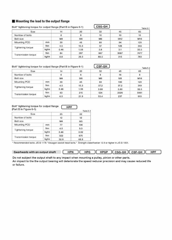
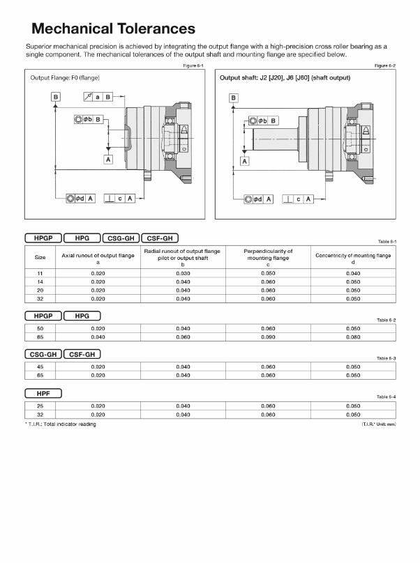

Table 5-2
Table 5-3
Bolt* tightening torque for output flange (Part B in Figure 4-1)
65453220148
M4304.5
0.46848.6
8M645
15.31.5628729.3
10M860373.886788.5
10M12941283.1
3067313
10M1612031932.57477763
mmNm
kgfmNm
kgfm
Bolt* tightening torque for output flange (Part B in Figure 4-1)
322512M4774.5
0.4632232.9
12M51009.0
0.9267568.9
mmNm
kgfmNm
kgfm
CSF-GH
HPF
Table 5-1Bolt* tightening torque for output flange (Part B in Figure 4-1)
65453220146
M4304.5
0.46636.5
6M645
15.31.5621521.9
6M860
37.23.8052453.4
16M810037.23.802326237
8M1612031932.55981610
mmNm
kgfmNm
kgfm
CSG-GH
HPN HPFHPG CSG-GH CSF-GHHPGPGearheads with an output shaft
Do not subject the output shaft to any impact when mounting a pulley, pinion or other parts. An impact to the the output bearing will deteriorate the speed reducer precision and may cause reduced life or failure.
SizeNumber of boltsBolt sizeMounting PCD
Tightening torque
Transmission torque
SizeNumber of boltsBolt sizeMounting PCD
Tightening torque
Transmission torque
* Recommended bolts: JIS B 1176 "Hexagon socket head bolts." Strength classification 12.9 or higher in JIS B 1051.
SizeNumber of boltsBolt sizeMounting PCD
Tightening torque
Transmission torque
Figure 6-2
Table 6-1
Table 6-2
Table 6-3
Table 6-4
Output Flange: F0 (�ange) Output shaft: J2 [J20], J6 [J60] (shaft output)
0.0500.0600.0600.060
0.0400.0500.0500.050
0.0300.0400.0400.040
0.0200.0200.0200.020
11142032
0.0600.090
0.0500.080
0.0400.060
0.0200.040
5065
0.0600.060
0.0500.050
0.0400.040
0.0200.020
4565
0.0600.060
0.0500.050
0.0400.040
0.0200.020
2532
Size Axial runout of output flangea
Radial runout of output flange pilot or output shaft
b
Perpendicularity ofmounting flange
cConcentricity of mounting flange
d
(T.I.R.* Unit: mm)
HPF
HPG
HPG CSG-GH CSF-GH
CSG-GH CSF-GH
HPGP
HPGP
Superior mechanical precision is achieved by integrating the output flange with a high-precision cross roller bearing as a single component. The mechanical tolerances of the output shaft and mounting flange are specified below.
* T.I.R.: Total indicator reading
Mechanical Tolerances
Figure 6-1
• Provisions for proper sealing to prevent grease leakage from the input shaft are incorporated into the gearhead. • A double lip Teflon oil seal is used for the output shaft (HPGP/HPG uses a single lip seal), gaskets or o-rings are used on all
mating surfaces, and non contact shielded bearing are used for the motor shaft coupling (Double sealed bearings (D type)are available as an option*) . On the CSG/CSF-GH series, non contact shielded bearing and a Teflon oil seal with a spring is used.
The standard lubrication for the HPG/HPGP/HPF/HPN series gearheads is grease.All gearheads are lubricated at the factory prior to shipment and additional application of grease during assembly is not required. The gearheads are lubricated for the life of the gear and do not require re-lubrication. High efficiency is achieved through the unique planetary gear design and grease selection.
HPG/HPGP/HPF/HPN Series
Lubricants
Ambient operating temperature range: –10℃ to +40℃
The lubricant may deteriorate if the ambient operating temperature is too high or too low. Please contact our sales office ordistributor for operation outside of the ambient operating temperature range.The temperature rise of the gear depends upon the operating cycle, ambient temperature and heat conduction and radiation as affected by the customers installation of the gear. A housing surface temperature of 70ºC is the maximum allowable limit.
(Common to all models)
• Contact us when using HarmonicDrive® CSG/CSF-GH series with the output shaft facing downward (motor on top) at aconstant load or rotating continuously in one direction.
(CSG/CSF-GH Series)
• Using the doubled sealed bearing (D type) for the HPGP/HPG series gearhead will result in a slightly lower efficiencycompared to the standard product.
• An oil seal without a spring is used in the input shaft side of HPG series with an input shaft (HPG-1U) and HPF series hollow shaft reducer. An option for an oil seal with a spring is available for improved seal reliability, however, the efficiency will beslightly lower (available for HPF and HPG series for sizes 14 and larger).
• Do not remove the screw plug and seal cap of the HPG series right angle gearhead. Removing them may cause leakage ofgrease or affect the precision of the gear.
(HPG/HPGP/HPF/HPN Series)
• Only use the recommended greases.• Provisions for proper sealing to prevent grease leakage are incorporated into the gearheads. However, please note that
some leakage may occur depending on the application or operating condition. Discuss other sealing options with ourapplications engineers.
• When mounting the gearhead horizontally position the gearhead so the rubber cap in the adapter flange is facing upwards.
(Common to all models)
* D type: Bearing with a rubber contact seal on both sides
Sealing
Prevention of grease and oil leakage
Lubricant
Mounting the load to the output flange
Harmonic Grease® SK-2 Manufacturer: Harmonic Drive Systems Inc.
(HPGP/HPG-14, 20, 32) (HPGP/HPG-11, 50, 65/HPF-25, 32)EPNOC Grease AP (N) 2 Manufacturer: Nippon Oil Co.
(HPG right angle gearhead/HPN)PYRONOC UNIVERSAL 00 Manufacturer: Nippon Oil Co.
Base oil: Refined mineral oilSoap radical: Lithium soapAdditive: Extreme pressure agent
and other Standard: NLGI No. 2
Consistency: 265 to 295 at 25°CDropping point: 198°CProduct appearance: Green
Base oil: Refined mineral oilSoap radical: UreaStandard: NLGI No. 00
Consistency: 420 at 25°CDropping point: 250°C or higherProduct appearance: Light yellow
Base oil: Refined mineral oilSoap radical: Lithium soapAdditive: Extreme pressure agent
and other Standard: NLGI No. 2
Consistency: 282 at 25°CDropping point: 200°CProduct appearance: Light brown
Lubrication
1010
109
108
107
20 40 60 80 100 120
SK-1ASK-2
Life of grease
LGTn (when the average load torque is equal to or less than the rated torque)
Grease quantity for Reference value of grease refill amount for replacement
SizeAmount: g 0.8 3.2 6.6 11.6 78.6
The life of the Harmonic Drive® gear is af fected by the grease performance. The grease performance varies with temperature and deteriorates with temperatures. Therefore, the grease will need to be changed sooner than usual when operating at higher temperatures. The graph on the right indicates when to change the grease based upon the temperature and the total number of input rotations when the average load torque is less than or equal to the rated output torque at 2000 rpm. Also, using the formula below, you can calculate when to change the grease when the average load torque exceeds the rated output torque at 2000 rpm.
Strictly observe the following instructions when changing the grease to avoid problems such as grease leakage or increase in running torque.
●Note that the amount of grease listed in Table 8-2 is the amount used to lubricate the gear at assembly. This should be usedas a reference. Do not exceed this amount when re-greasing the gearhead.●Remove grease from the gearhead and refill it with the same quantity. The adverse effects listed above normally do not occur until the
gear has been re-greased 2 times. When re-greasing 3 times or more, it is essential to remove grease (using air pressure or other means) before re-lubricating with the same amount of grease that was removed.
Figure 8-1
Table 8-1
Formula 8-1
Table 8-2
TrTav( )3
LGT = LGTn ×
CSG-GH/CSF-GH Series
The standard lubrication for the CGS-GH / CSF-GH series gearheads is grease.All gearheads are lubricated at the factory prior to shipment and additional application of grease during assembly is not necessary.
This has been developed exclusively for HarmonicDrive® gears and is excellent in durability and efficiency compared to commercial general-purpose grease.
This has been developed exclusively for smaller sized HarmonicDrive®gears and allows smooth wave generator rotation.
Precautions when changing the grease
Lubricants
Harmonic Grease® SK-1A Manufacturer: Harmonic Drive Systems Inc.
(Size 20, 32, 45, 65) (Size 14)Harmonic Grease® SK-2 Manufacturer: Harmonic Drive Systems Inc.
Base oil: Refined mineral oilSoap radical: Lithium soapAdditive: Extreme pressure agent
and other Standard: NLGI No. 2
Consistency: 265 to 295 at 25°CDropping point: 197°CProduct appearance: Yellow
Base oil: Refined mineral oilSoap radical: Lithium soapAdditive: Extreme pressure agent
and other Standard: NLGI No. 2
Consistency: 265 to 295 at 25°CDropping point: 198°CProduct appearance: Green
Ambient operating temperature range: –10℃ to +40℃
When to change the grease
The lubricant may deteriorate if the ambient operating temperature is too high or too low. Please contact our sales office ordistributor for operation outside of the ambient operating temperature range.The temperature rise of the gear depends upon the operating cycle, ambient temperature and heat conduction and radiation as affected by the customers installation of the gear. A housing surface temperature of 70ºC is the maximum allowable limit.
Formula to calculate the grease change interval when the average loadtorque exceeds the rated torque
Formula symbols
LGT
LGTn
Tr
Tav
Grease change interval when Tav > Tr
Grease change interval when Tav <= Tr
Average load torque
Output torque at 2000 rpm
Input rotations
Input rotations
Nm, kgfm
Nm, kgfm
When to change the grease: LGTn (when the average load torque is equal to or less than the ratedoutput torque at 2000 rpm)
Num
ber o
f inp
ut re
volu
tions
Life of wave generator
Grease temperature (oC)
* L10 Life of wave generator bearing
14 20 32 45 65
Harmonic Drive LLC247 Lynnfield Street, Peabody, MAwww.harmonicdrive.netHarmonic Drive, Harmonic Grease and Harmonic Planetary are registered trademarks of Harmonic Drive LLC.
(HPG-X-R)MULTEMP AC-P Manufacturer: KYODO YUSHI CO, LTD
Base oil: Composite hydrocarbon oil and diester
Thickening agent: Lithium soapAdditive: Extreme pressure
and others
Standard: NLGI No. 2 Consistency: 280 at 25°CDropping point: 200°CColor: Black viscose
20150610P/N 7381184
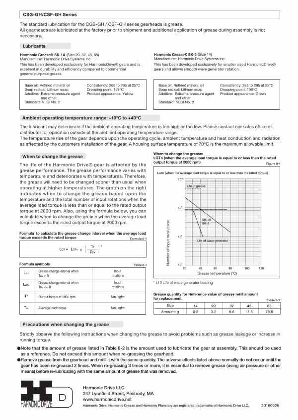
Table 5-2
Table 5-3
Bolt* tightening torque for output flange (Part B in Figure 4-1)
65453220148
M4304.5
0.46848.6
8M645
15.31.5628729.3
10M860373.886788.5
10M12941283.1
3067313
10M1612031932.57477763
mmNm
kgfmNm
kgfm
Bolt* tightening torque for output flange (Part B in Figure 4-1)
322512M4774.5
0.4632232.9
12M51009.0
0.9267568.9
mmNm
kgfmNm
kgfm
CSF-GH
HPF
Table 5-1Bolt* tightening torque for output flange (Part B in Figure 4-1)
65453220146
M4304.5
0.46636.5
6M645
15.31.5621521.9
6M860
37.23.8052453.4
16M810037.23.802326237
8M1612031932.55981610
mmNm
kgfmNm
kgfm
CSG-GH
HPN HPFHPG CSG-GH CSF-GHHPGPGearheads with an output shaft
Do not subject the output shaft to any impact when mounting a pulley, pinion or other parts. An impact to the the output bearing will deteriorate the speed reducer precision and may cause reduced life or failure.
SizeNumber of boltsBolt sizeMounting PCD
Tightening torque
Transmission torque
SizeNumber of boltsBolt sizeMounting PCD
Tightening torque
Transmission torque
* Recommended bolts: JIS B 1176 "Hexagon socket head bolts." Strength classification 12.9 or higher in JIS B 1051.
SizeNumber of boltsBolt sizeMounting PCD
Tightening torque
Transmission torque
Figure 6-2
Table 6-1
Table 6-2
Table 6-3
Table 6-4
Output Flange: F0 (�ange) Output shaft: J2 [J20], J6 [J60] (shaft output)
0.0500.0600.0600.060
0.0400.0500.0500.050
0.0300.0400.0400.040
0.0200.0200.0200.020
11142032
0.0600.090
0.0500.080
0.0400.060
0.0200.040
5065
0.0600.060
0.0500.050
0.0400.040
0.0200.020
4565
0.0600.060
0.0500.050
0.0400.040
0.0200.020
2532
Size Axial runout of output flangea
Radial runout of output flange pilot or output shaft
b
Perpendicularity ofmounting flange
cConcentricity of mounting flange
d
(T.I.R.* Unit: mm)
HPF
HPG
HPG CSG-GH CSF-GH
CSG-GH CSF-GH
HPGP
HPGP
Superior mechanical precision is achieved by integrating the output flange with a high-precision cross roller bearing as a single component. The mechanical tolerances of the output shaft and mounting flange are specified below.
* T.I.R.: Total indicator reading
Mechanical Tolerances
Figure 6-1
• Provisions for proper sealing to prevent grease leakage from the input shaft are incorporated into the gearhead. • A double lip Teflon oil seal is used for the output shaft (HPGP/HPG uses a single lip seal), gaskets or o-rings are used on all
mating surfaces, and non contact shielded bearing are used for the motor shaft coupling (Double sealed bearings (D type)are available as an option*) . On the CSG/CSF-GH series, non contact shielded bearing and a Teflon oil seal with a spring is used.
The standard lubrication for the HPG/HPGP/HPF/HPN series gearheads is grease.All gearheads are lubricated at the factory prior to shipment and additional application of grease during assembly is not required. The gearheads are lubricated for the life of the gear and do not require re-lubrication. High efficiency is achieved through the unique planetary gear design and grease selection.
HPG/HPGP/HPF/HPN Series
Lubricants
Ambient operating temperature range: –10℃ to +40℃
The lubricant may deteriorate if the ambient operating temperature is too high or too low. Please contact our sales office ordistributor for operation outside of the ambient operating temperature range.The temperature rise of the gear depends upon the operating cycle, ambient temperature and heat conduction and radiation as affected by the customers installation of the gear. A housing surface temperature of 70ºC is the maximum allowable limit.
(Common to all models)
• Contact us when using HarmonicDrive® CSG/CSF-GH series with the output shaft facing downward (motor on top) at aconstant load or rotating continuously in one direction.
(CSG/CSF-GH Series)
• Using the doubled sealed bearing (D type) for the HPGP/HPG series gearhead will result in a slightly lower efficiencycompared to the standard product.
• An oil seal without a spring is used in the input shaft side of HPG series with an input shaft (HPG-1U) and HPF series hollow shaft reducer. An option for an oil seal with a spring is available for improved seal reliability, however, the efficiency will beslightly lower (available for HPF and HPG series for sizes 14 and larger).
• Do not remove the screw plug and seal cap of the HPG series right angle gearhead. Removing them may cause leakage ofgrease or affect the precision of the gear.
(HPG/HPGP/HPF/HPN Series)
• Only use the recommended greases.• Provisions for proper sealing to prevent grease leakage are incorporated into the gearheads. However, please note that
some leakage may occur depending on the application or operating condition. Discuss other sealing options with ourapplications engineers.
• When mounting the gearhead horizontally position the gearhead so the rubber cap in the adapter flange is facing upwards.
(Common to all models)
* D type: Bearing with a rubber contact seal on both sides
Sealing
Prevention of grease and oil leakage
Lubricant
Mounting the load to the output flange
Harmonic Grease® SK-2 Manufacturer: Harmonic Drive Systems Inc.
(HPGP/HPG-14, 20, 32) (HPGP/HPG-11, 50, 65/HPF-25, 32)EPNOC Grease AP (N) 2 Manufacturer: Nippon Oil Co.
(HPG right angle gearhead/HPN)PYRONOC UNIVERSAL 00 Manufacturer: Nippon Oil Co.
Base oil: Refined mineral oilSoap radical: Lithium soapAdditive: Extreme pressure agent
and other Standard: NLGI No. 2
Consistency: 265 to 295 at 25°CDropping point: 198°CProduct appearance: Green
Base oil: Refined mineral oilSoap radical: UreaStandard: NLGI No. 00
Consistency: 420 at 25°CDropping point: 250°C or higherProduct appearance: Light yellow
Base oil: Refined mineral oilSoap radical: Lithium soapAdditive: Extreme pressure agent
and other Standard: NLGI No. 2
Consistency: 282 at 25°CDropping point: 200°CProduct appearance: Light brown
Lubrication
1010
109
108
107
20 40 60 80 100 120
SK-1ASK-2
Life of grease
LGTn (when the average load torque is equal to or less than the rated torque)
Grease quantity for Reference value of grease refill amount for replacement
SizeAmount: g 0.8 3.2 6.6 11.6 78.6
The life of the Harmonic Drive® gear is af fected by the grease performance. The grease performance varies with temperature and deteriorates with temperatures. Therefore, the grease will need to be changed sooner than usual when operating at higher temperatures. The graph on the right indicates when to change the grease based upon the temperature and the total number of input rotations when the average load torque is less than or equal to the rated output torque at 2000 rpm. Also, using the formula below, you can calculate when to change the grease when the average load torque exceeds the rated output torque at 2000 rpm.
Strictly observe the following instructions when changing the grease to avoid problems such as grease leakage or increase in running torque.
●Note that the amount of grease listed in Table 8-2 is the amount used to lubricate the gear at assembly. This should be usedas a reference. Do not exceed this amount when re-greasing the gearhead.●Remove grease from the gearhead and refill it with the same quantity. The adverse effects listed above normally do not occur until the
gear has been re-greased 2 times. When re-greasing 3 times or more, it is essential to remove grease (using air pressure or other means) before re-lubricating with the same amount of grease that was removed.
Figure 8-1
Table 8-1
Formula 8-1
Table 8-2
TrTav( )3
LGT = LGTn ×
CSG-GH/CSF-GH Series
The standard lubrication for the CGS-GH / CSF-GH series gearheads is grease.All gearheads are lubricated at the factory prior to shipment and additional application of grease during assembly is not necessary.
This has been developed exclusively for HarmonicDrive® gears and is excellent in durability and efficiency compared to commercial general-purpose grease.
This has been developed exclusively for smaller sized HarmonicDrive®gears and allows smooth wave generator rotation.
Precautions when changing the grease
Lubricants
Harmonic Grease® SK-1A Manufacturer: Harmonic Drive Systems Inc.
(Size 20, 32, 45, 65) (Size 14)Harmonic Grease® SK-2 Manufacturer: Harmonic Drive Systems Inc.
Base oil: Refined mineral oilSoap radical: Lithium soapAdditive: Extreme pressure agent
and other Standard: NLGI No. 2
Consistency: 265 to 295 at 25°CDropping point: 197°CProduct appearance: Yellow
Base oil: Refined mineral oilSoap radical: Lithium soapAdditive: Extreme pressure agent
and other Standard: NLGI No. 2
Consistency: 265 to 295 at 25°CDropping point: 198°CProduct appearance: Green
Ambient operating temperature range: –10℃ to +40℃
When to change the grease
The lubricant may deteriorate if the ambient operating temperature is too high or too low. Please contact our sales office ordistributor for operation outside of the ambient operating temperature range.The temperature rise of the gear depends upon the operating cycle, ambient temperature and heat conduction and radiation as affected by the customers installation of the gear. A housing surface temperature of 70ºC is the maximum allowable limit.
Formula to calculate the grease change interval when the average loadtorque exceeds the rated torque
Formula symbols
LGT
LGTn
Tr
Tav
Grease change interval when Tav > Tr
Grease change interval when Tav <= Tr
Average load torque
Output torque at 2000 rpm
Input rotations
Input rotations
Nm, kgfm
Nm, kgfm
When to change the grease: LGTn (when the average load torque is equal to or less than the ratedoutput torque at 2000 rpm)N
umbe
r of i
nput
revo
lutio
ns
Life of wave generator
Grease temperature (oC)
* L10 Life of wave generator bearing
14 20 32 45 65
Harmonic Drive LLC247 Lynnfield Street, Peabody, MAwww.harmonicdrive.netHarmonic Drive, Harmonic Grease and Harmonic Planetary are registered trademarks of Harmonic Drive LLC.
(HPG-X-R)MULTEMP AC-P Manufacturer: KYODO YUSHI CO, LTD
Base oil: Composite hydrocarbon oil and diester
Thickening agent: Lithium soapAdditive: Extreme pressure
and others
Standard: NLGI No. 2 Consistency: 280 at 25°CDropping point: 200°CColor: Black viscose
20160926