Embed Size (px)
Citation preview
Safety. Detection. Control.
Safety Contactless Sensors and Devices
SAFETY SENSORS
Product catalogueIssue 1
2
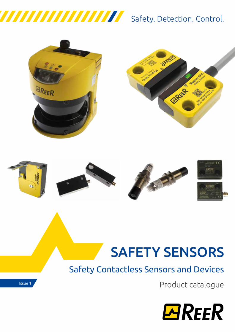
Magnus RFID: next generation sensors for machine safety
Magnus RFID RFID safety switchSee page 4
OVERVIEWSAFETY CONTACTLESS SENSORS AND DEVICES
Available with 22 or 78 mm interaxis
State-of-the-art RFID technology
M12 connector pigtail or 5 meters cable
3 different coding levels
IP67 and IP69K approved
Anti-tampering protective caps
Status LED
3
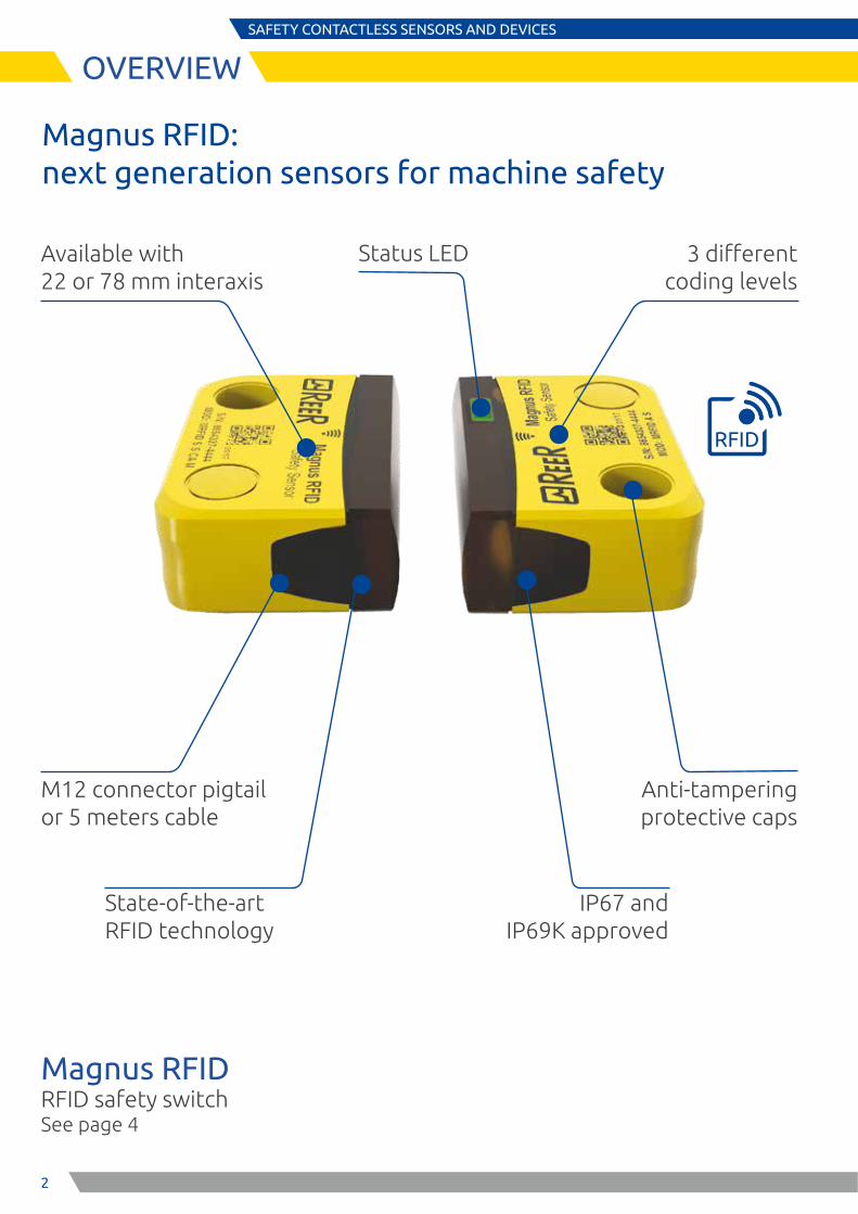
Pharo Type 3 laser scannerSee page 17
Ilion Type 2 safety photocells See page 21
Ulisse Type 2 safety photocells See page 23
Magnus MG
Magnetic safety switches See page 11
Safety switch with guard lockingSee page 26
Safety Sin/Cos incremental encoder See page 25
SAFETY CONTACTLESS SENSORS AND DEVICES
OVERVIEW
4
MAGNUS RFIDPL e, SIL 3 RFID SAFETY SENSORS
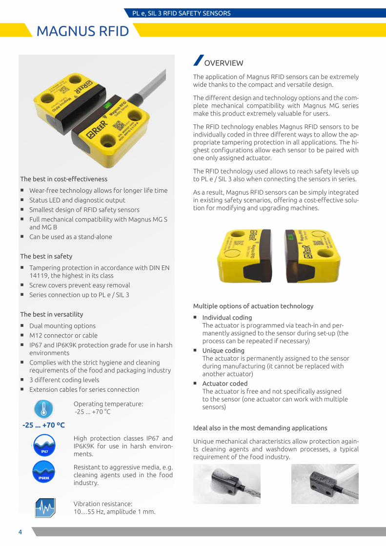
The best in cost-effectiveness
■ Wear-free technology allows for longer life time ■ Status LED and diagnostic output ■ Smallest design of RFID safety sensors ■ Full mechanical compatibility with Magnus MG S
and MG B ■ Can be used as a stand-alone
The best in safety
■ Tampering protection in accordance with DIN EN 14119, the highest in its class
■ Screw covers prevent easy removal ■ Series connection up to PL e / SIL 3
The best in versatility
■ Dual mounting options ■ M12 connector or cable ■ IP67 and IP6K9K protection grade for use in harsh
environments ■ Complies with the strict hygiene and cleaning
requirements of the food and packaging industry ■ 3 different coding levels ■ Extension cables for series connection
-25 ... +70 ºC
Operating temperature: -25 ... +70 °C
High protection classes IP67 and IP6K9K for use in harsh environ-ments.
Resistant to aggressive media, e.g. cleaning agents used in the food industry.
Vibration resistance: 10…55 Hz, amplitude 1 mm.
IP67IP65
OVERVIEW
The application of Magnus RFID sensors can be extremely wide thanks to the compact and versatile design.
The different design and technology options and the com-plete mechanical compatibility with Magnus MG series make this product extremely valuable for users.
The RFID technology enables Magnus RFID sensors to be individually coded in three different ways to allow the ap-propriate tampering protection in all applications. The hi-ghest configurations allow each sensor to be paired with one only assigned actuator.
The RFID technology used allows to reach safety levels up to PL e / SIL 3 also when connecting the sensors in series.
As a result, Magnus RFID sensors can be simply integrated in existing safety scenarios, offering a cost-effective solu-tion for modifying and upgrading machines.
Multiple options of actuation technology
■ Individual coding The actuator is programmed via teach-in and per-manently assigned to the sensor during set-up (the process can be repeated if necessary)
■ Unique coding The actuator is permanently assigned to the sensor during manufacturing (it cannot be replaced with another actuator)
■ Actuator coded The actuator is free and not specifically assigned to the sensor (one actuator can work with multiple sensors)
Ideal also in the most demanding applications
Unique mechanical characteristics allow protection again-ts cleaning agents and washdown processes, a typical requirement of the food industry.
IP6K9K
5
MAGNUS RFIDPL e, SIL 3 RFID SAFETY SENSORS
SERIES CONNECTION WITH MAXIMUM SAFETY
Reliable evaluation, e.g. with the modular safety
controller Mosaic...
…or with the AD SR1 configurable safety
control unit
Up to (PL e Performance Level) according to EN ISO 13849-1
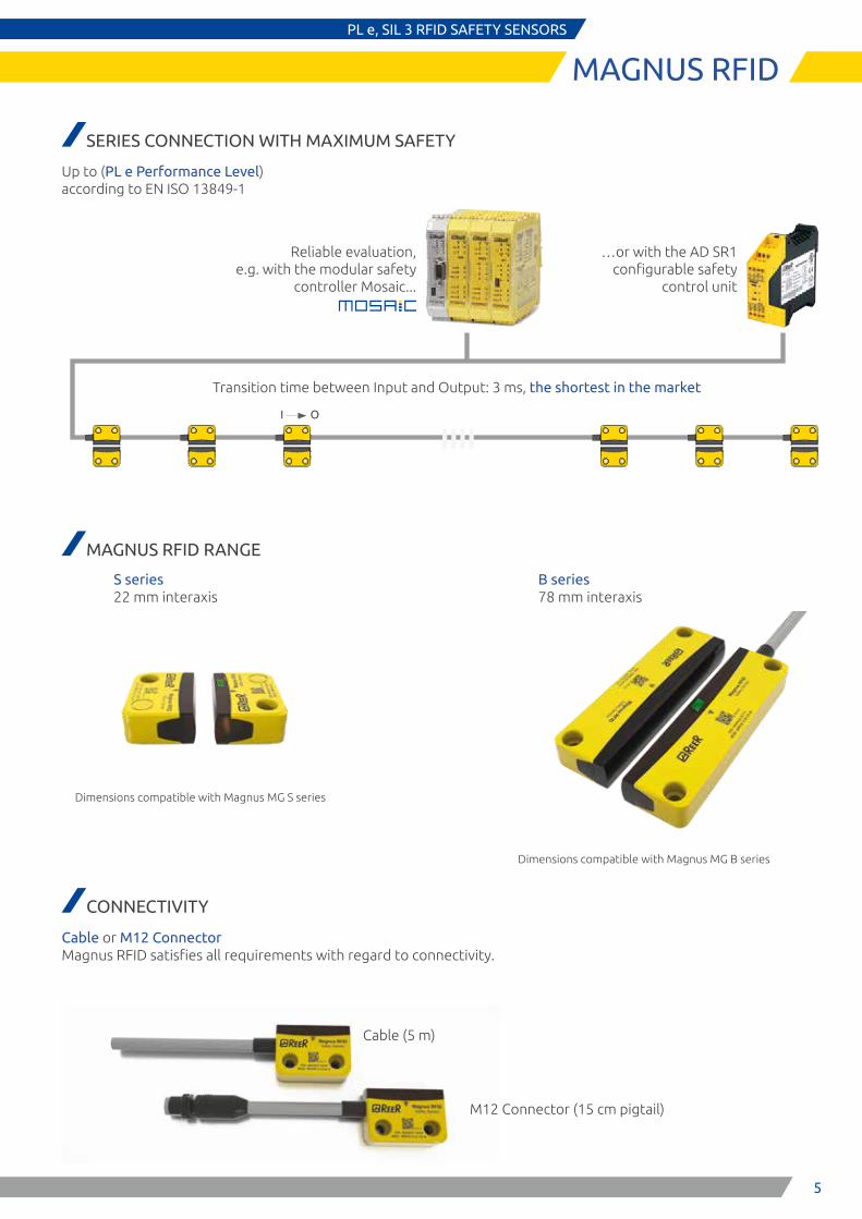
MAGNUS RFID RANGE
CONNECTIVITY
Cable or M12 Connector Magnus RFID satisfies all requirements with regard to connectivity.
Cable (5 m)
M12 Connector (15 cm pigtail)
S series 22 mm interaxis
B series 78 mm interaxis
Dimensions compatible with Magnus MG S series
Dimensions compatible with Magnus MG B series
Transition time between Input and Output: 3 ms, the shortest in the market
I O
6
E S P E
MAGNUS RFIDPL e, SIL 3 RFID SAFETY SENSORS
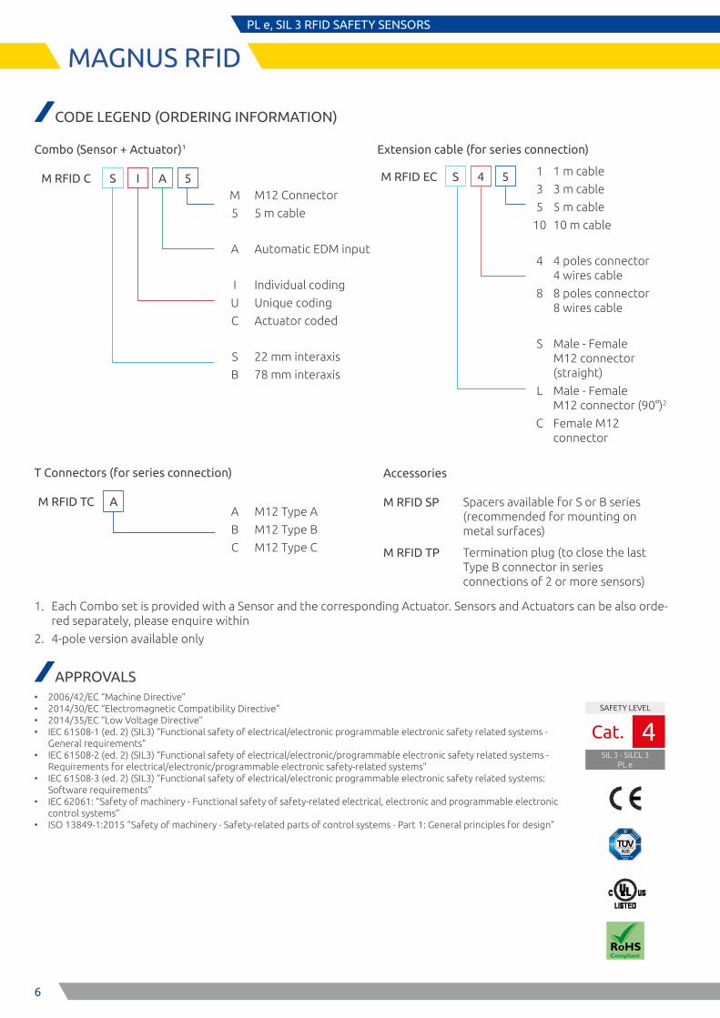
CODE LEGEND (ORDERING INFORMATION)
Combo (Sensor + Actuator)1
M RFID C S I A 5M
5
A
I
U
C
S
B
M12 Connector
5 m cable
Automatic EDM input
Individual coding
Unique coding
Actuator coded
22 mm interaxis
78 mm interaxis
Extension cable (for series connection)
M RFID EC S 4 5 1
3
5
10
4
8
S
L
C
1 m cable
3 m cable
5 m cable
10 m cable
4 poles connector 4 wires cable
8 poles connector 8 wires cable
Male - Female M12 connector (straight)
Male - Female M12 connector (90°)2
Female M12 connector
T Connectors (for series connection)
M RFID TC AA
B
C
M12 Type A
M12 Type B
M12 Type C
Accessories
M RFID SP
M RFID TP
Spacers available for S or B series (recommended for mounting on metal surfaces)
Termination plug (to close the last Type B connector in series connections of 2 or more sensors)
APPROVALS • 2006/42/EC “Machine Directive” • 2014/30/EC “Electromagnetic Compatibility Directive” • 2014/35/EC “Low Voltage Directive” • IEC 61508-1 (ed. 2) (SIL3) “Functional safety of electrical/electronic programmable electronic safety related systems -
General requirements” • IEC 61508-2 (ed. 2) (SIL3) “Functional safety of electrical/electronic/programmable electronic safety related systems -
Requirements for electrical/electronic/programmable electronic safety-related systems” • IEC 61508-3 (ed. 2) (SIL3) “Functional safety of electrical/electronic programmable electronic safety related systems:
Software requirements” • IEC 62061: “Safety of machinery - Functional safety of safety-related electrical, electronic and programmable electronic
control systems” • ISO 13849-1:2015 “Safety of machinery - Safety-related parts of control systems - Part 1: General principles for design”
SAFETY LEVEL
SIL 3 - SILCL 3PL e
Cat. 4
1. Each Combo set is provided with a Sensor and the corresponding Actuator. Sensors and Actuators can be also orde-red separately, please enquire within
2. 4-pole version available only
7
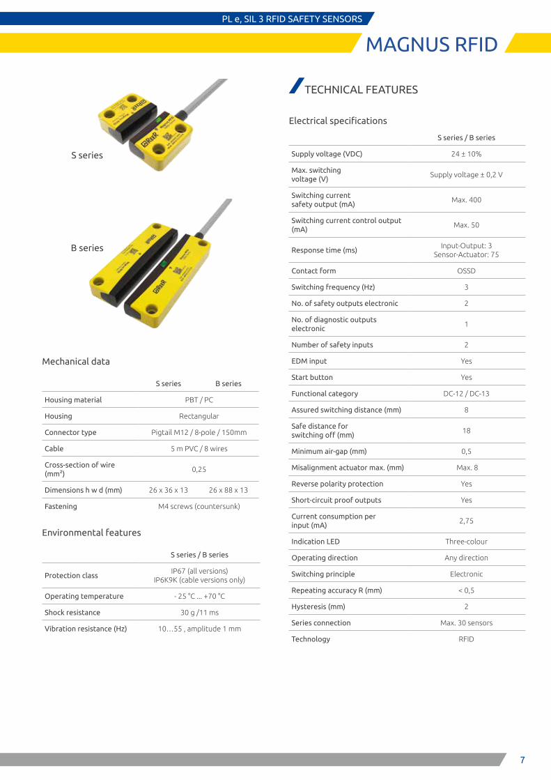
S series
B series
MAGNUS RFIDPL e, SIL 3 RFID SAFETY SENSORS
Mechanical data
S series B series
Housing material PBT / PC
Housing Rectangular
Connector type Pigtail M12 / 8-pole / 150mm
Cable 5 m PVC / 8 wires
Cross-section of wire (mm2)
0,25
Dimensions h w d (mm) 26 x 36 x 13 26 x 88 x 13
Fastening M4 screws (countersunk)
Environmental features
S series / B series
Protection classIP67 (all versions)
IP6K9K (cable versions only)
Operating temperature - 25 °C ... +70 °C
Shock resistance 30 g /11 ms
Vibration resistance (Hz) 10…55 , amplitude 1 mm
TECHNICAL FEATURES
Electrical specifications
S series / B series
Supply voltage (VDC) 24 ± 10%
Max. switching voltage (V)
Supply voltage ± 0,2 V
Switching current safety output (mA)
Max. 400
Switching current control output (mA)
Max. 50
Response time (ms)Input-Output: 3
Sensor-Actuator: 75
Contact form OSSD
Switching frequency (Hz) 3
No. of safety outputs electronic 2
No. of diagnostic outputs electronic
1
Number of safety inputs 2
EDM input Yes
Start button Yes
Functional category DC-12 / DC-13
Assured switching distance (mm) 8
Safe distance for switching off (mm)
18
Minimum air-gap (mm) 0,5
Misalignment actuator max. (mm) Max. 8
Reverse polarity protection Yes
Short-circuit proof outputs Yes
Current consumption per input (mA)
2,75
Indication LED Three-colour
Operating direction Any direction
Switching principle Electronic
Repeating accuracy R (mm) < 0,5
Hysteresis (mm) 2
Series connection Max. 30 sensors
Technology RFID
8
MAGNUS RFIDPL e, SIL 3 RFID SAFETY SENSORS
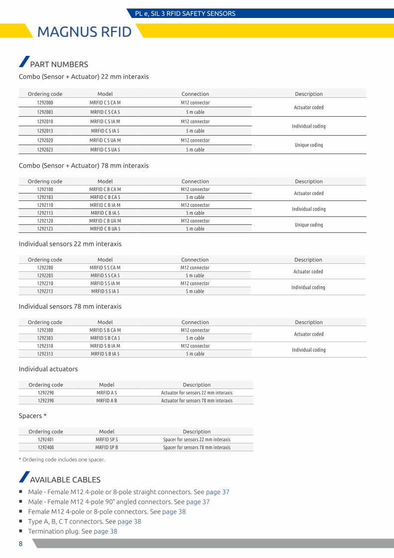
PART NUMBERS
Combo (Sensor + Actuator) 22 mm interaxis
Ordering code Model Connection Description
1292000 MRFID C S CA M M12 connectorActuator coded
1292003 MRFID C S CA 5 5 m cable
1292010 MRFID C S IA M M12 connectorIndividual coding
1292013 MRFID C S IA 5 5 m cable
1292020 MRFID C S UA M M12 connectorUnique coding
1292023 MRFID C S UA 5 5 m cable
Combo (Sensor + Actuator) 78 mm interaxis
Ordering code Model Connection Description
1292100 MRFID C B CA M M12 connectorActuator coded
1292103 MRFID C B CA 5 5 m cable
1292110 MRFID C B IA M M12 connectorIndividual coding
1292113 MRFID C B IA 5 5 m cable
1292120 MRFID C B UA M M12 connectorUnique coding
1292123 MRFID C B UA 5 5 m cable
Individual sensors 22 mm interaxis
Ordering code Model Connection Description
1292200 MRFID S S CA M M12 connectorActuator coded
1292203 MRFID S S CA 5 5 m cable
1292210 MRFID S S IA M M12 connectorIndividual coding
1292213 MRFID S S IA 5 5 m cable
Individual sensors 78 mm interaxis
Ordering code Model Connection Description
1292300 MRFID S B CA M M12 connectorActuator coded
1292303 MRFID S B CA 5 5 m cable
1292310 MRFID S B IA M M12 connectorIndividual coding
1292313 MRFID S B IA 5 5 m cable
Individual actuators
Ordering code Model Description
1292290 MRFID A S Actuator for sensors 22 mm interaxis
1292390 MRFID A B Actuator for sensors 78 mm interaxis
Spacers *
Ordering code Model Description
1292401 MRFID SP S Spacer for sensors 22 mm interaxis
1292400 MRFID SP B Spacer for sensors 78 mm interaxis
* Ordering code includes one spacer.
AVAILABLE CABLES ■ Male - Female M12 4-pole or 8-pole straight connectors. See page 37 ■ Male - Female M12 4-pole 90° angled connectors. See page 37 ■ Female M12 4-pole or 8-pole connectors. See page 38 ■ Type A, B, C T connectors. See page 38 ■ Termination plug. See page 38
9
A
48
8
B
8
4 4
C
2
43
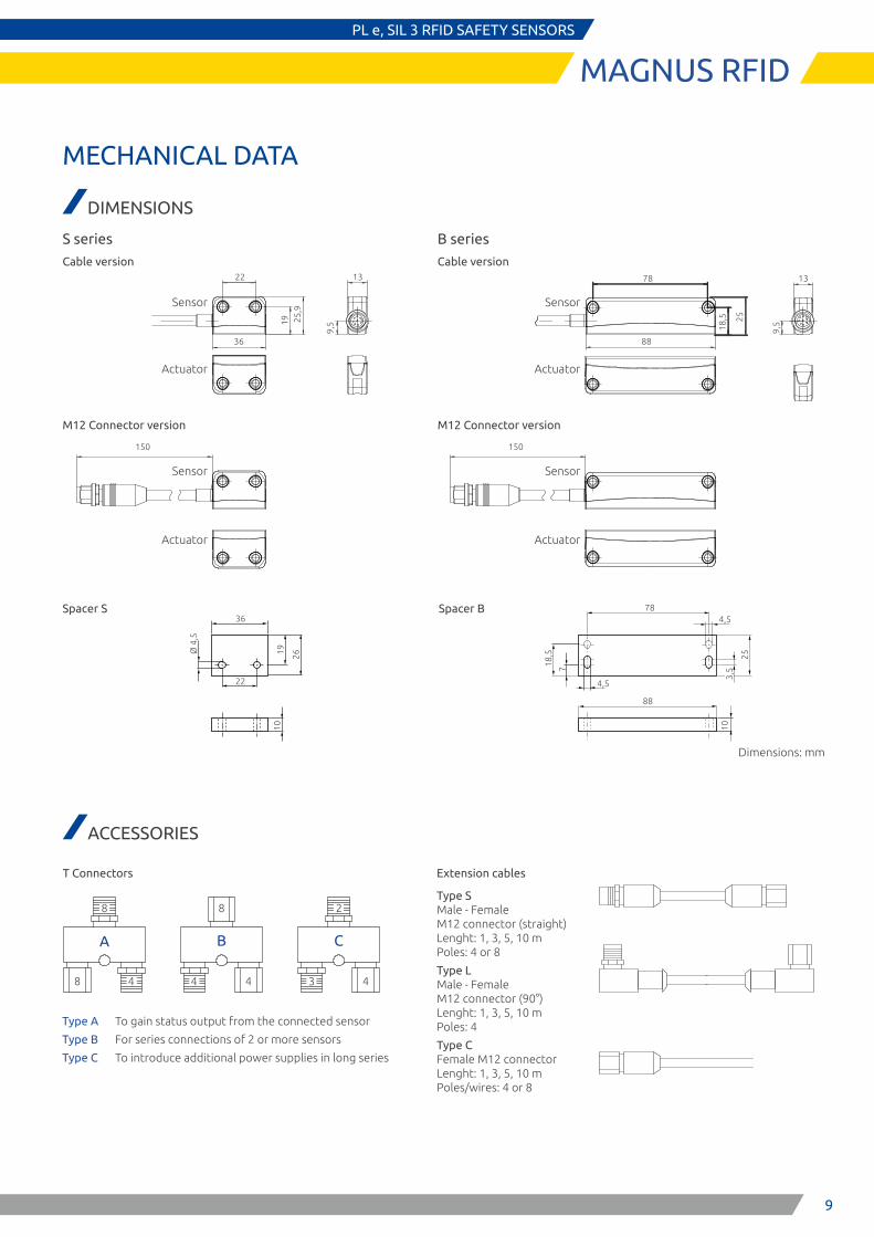
Extension cables
Type S Male - Female M12 connector (straight) Lenght: 1, 3, 5, 10 m Poles: 4 or 8
Type L Male - Female M12 connector (90°) Lenght: 1, 3, 5, 10 m Poles: 4
Type C Female M12 connector Lenght: 1, 3, 5, 10 m Poles/wires: 4 or 8
MAGNUS RFIDPL e, SIL 3 RFID SAFETY SENSORS
MECHANICAL DATA
DIMENSIONS
9,5
132219 25
,9
36
9,5
1378
18,5 25
88
150150
Ø 4
,5
22
36
19 26
10
4,5
78
25
10
4,5
18,5
7
88
3,5
Sensor
Sensor
Sensor
Sensor
Actuator
Actuator Actuator
Actuator
Cable version
M12 Connector version
Cable version
S series B series
T Connectors
Dimensions: mm
ACCESSORIES
Type A To gain status output from the connected sensor
Type B For series connections of 2 or more sensors
Type C To introduce additional power supplies in long series
Spacer S Spacer B
M12 Connector version
10
MAGNUS RFIDPL e, SIL 3 RFID SAFETY SENSORS
8
8
8
8
44
4
8
44
2
4
4 4
3
M RFID EC L 4 1M RFID EC L 4 3M RFID EC L 4 5M RFID EC L 4 10
M RFID EC S 8 1M RFID EC S 8 3M RFID EC S 8 5M RFID EC S 8 10
M RFID TC B M RFID TC BM RFID TC CAdditionalpower supply
Seriesconnection
Seriesconnection
Male - FemaleM12 connector (90°)Lenght: 1, 3, 5, 10 mPoles: 4
Male - FemaleM12 connector (straight)Lenght: 1, 3, 5, 10 mPoles: 8
Male - FemaleM12 connector (straight)Lenght: 1, 3, 5, 10 mPoles: 4
Female M12 connectorLenght: 1, 3, 5, 10 mPoles/wires: 4
Female M12 connectorLenght: 1, 3, 5, 10 mPoles/wires: 4
Female M12 connectorLenght: 1, 3, 5, 10 mPoles/wires: 8
Male - FemaleM12 connector (90°)Lenght: 1, 3, 5, 10 mPoles: 4
M RFID TPTermination plug
Status outputM RFID TC A
M RFID C S seriesM RFID C B series
M RFID C S seriesM RFID C B series
M RFID EC C 4 1M RFID EC C 4 3M RFID EC C 4 5M RFID EC C 4 10
M RFID EC C 4 1M RFID EC C 4 3M RFID EC C 4 5M RFID EC C 4 10
M RFID EC C 4 1M RFID EC C 4 3M RFID EC C 4 5M RFID EC C 4 10
M RFID EC S 4 1M RFID EC S 4 3M RFID EC S 4 5M RFID EC S 4 10
M RFID EC L 4 1M RFID EC L 4 3M RFID EC L 4 5M RFID EC L 4 10
Type B
48
8
Type A
Type BType C
4 4 4
8
4
4
4
4
M RFID EC C 8 1M RFID EC C 8 3M RFID EC C 8 5M RFID EC C 8 10
M RFID C S seriesM RFID C B series
8 8
bn 24V DC
EDM/restart sw
wsbl
Control 0V DC
Q2 Q1
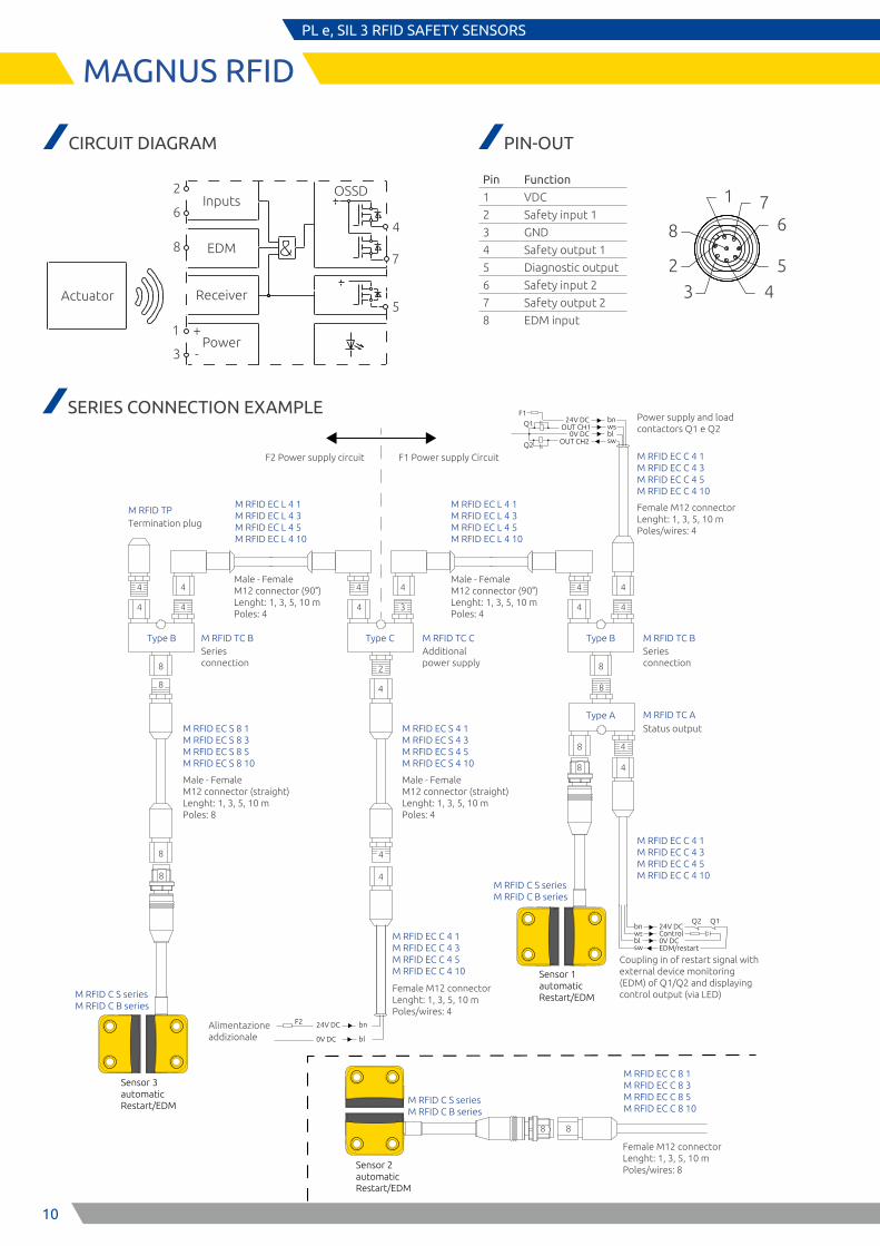
Coupling in of restart signal with external device monitoring (EDM) of Q1/Q2 and displaying control output (via LED)
bn24V DC
OUT CH2 sw
wsbl
OUT CH10V DC
Power supply and load contactors Q1 e Q2
Q2
Q1
F1
bn24V DC
bl
F2
0V DC
Alimentazione addizionale
F1 Power supply CircuitF2 Power supply circuit
Sensor 1automatic Restart/EDM
Sensor 2automatic Restart/EDM
Sensor 3automatic Restart/EDM
SERIES CONNECTION EXAMPLE
Inputs
EDM
+1
3Power
Receiver
8
2
64
7
5
-
OSSD
Actuator
8
2
6
3 4
5
71
CIRCUIT DIAGRAM PIN-OUT
Pin Function
1 VDC
2 Safety input 1
3 GND
4 Safety output 1
5 Diagnostic output
6 Safety input 2
7 Safety output 2
8 EDM input
11
3 1
4 2
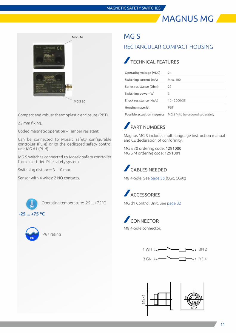
MAGNUS MGMAGNETIC SAFETY SWITCHES
MG S 20
MG S M
Compact and robust thermoplastic enclosure (PBT).
22 mm fixing.
Coded magnetic operation – Tamper resistant.
Can be connected to Mosaic safety configurable controller (PL e) or to the dedicated safety control unit MG d1 (PL d).
MG S switches connected to Mosaic safety controller form a certified PL e safety system.
Switching distance: 3 - 10 mm.
Sensor with 4 wires: 2 NO contacts.
-25 ... +75 ºC
IP67IP65
Operating temperature: -25 ... +75 °C
IP67 rating
MG SRECTANGULAR COMPACT HOUSING
TECHNICAL FEATURES
Operating voltage (VDC) 24
Switching current (mA) Max. 100
Series resistance (Ohm) 22
Switching power (W) 3
Shock resistance (Hz/g) 10 - 2000/35
Housing material PBT
Possible actuation magnets MG S M to be ordered separately
PART NUMBERS
Magnus MG S includes multi-language instruction manual and CE declaration of conformity.
MG S 20 ordering code: 1291000 MG S M ordering code: 1291001
CABLES NEEDED
M8 4-pole. See page 35 (CGx, CG9x)
ACCESSORIES
MG d1 Control Unit. See page 32
CONNECTOR
M8 4-pole connector.
1 WH
3 GN
BN 2
YE 4
M8x
1
12
MAGNUS MGMAGNETIC SAFETY SWITCHES
APPROVALS
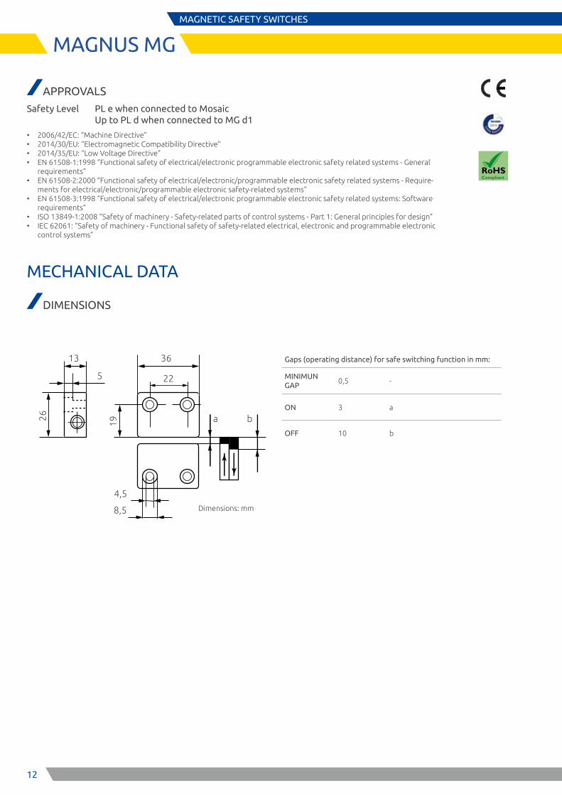
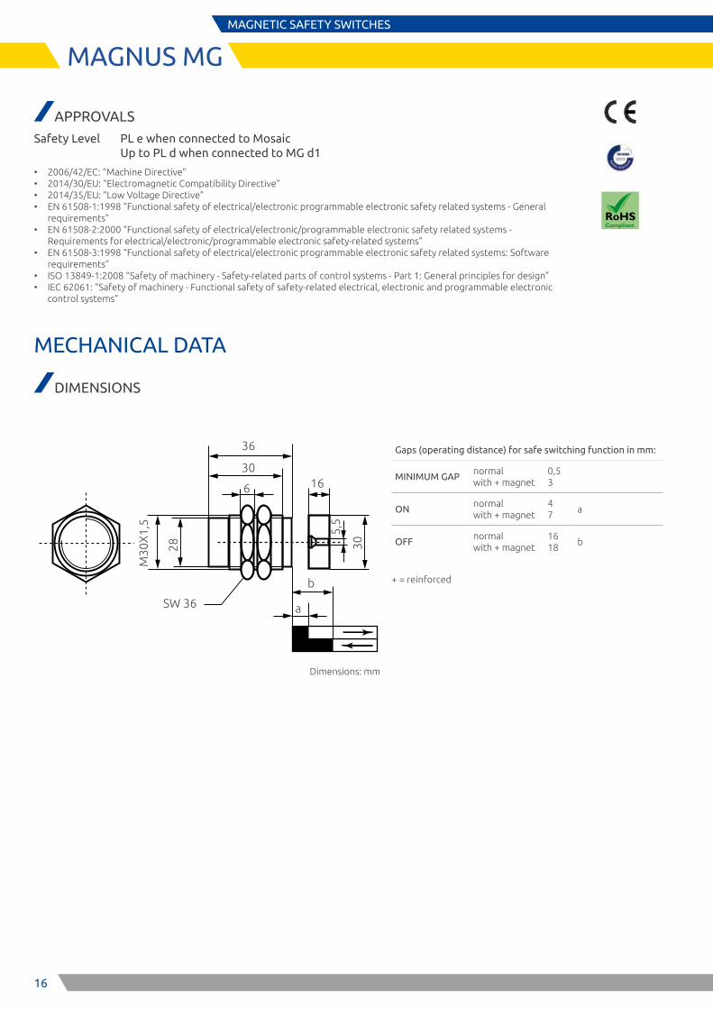
Safety Level PL e when connected to Mosaic Up to PL d when connected to MG d1
• 2006/42/EC: “Machine Directive” • 2014/30/EU: “Electromagnetic Compatibility Directive” • 2014/35/EU: “Low Voltage Directive” • EN 61508-1:1998 “Functional safety of electrical/electronic programmable electronic safety related systems - General
requirements” • EN 61508-2:2000 “Functional safety of electrical/electronic/programmable electronic safety related systems - Require-
ments for electrical/electronic/programmable electronic safety-related systems” • EN 61508-3:1998 “Functional safety of electrical/electronic programmable electronic safety related systems: Software
requirements” • ISO 13849-1:2008 “Safety of machinery - Safety-related parts of control systems - Part 1: General principles for design” • IEC 62061: “Safety of machinery - Functional safety of safety-related electrical, electronic and programmable electronic
control systems”
MECHANICAL DATA
DIMENSIONS
Gaps (operating distance) for safe switching function in mm:
MINIMUN GAP
0,5 -
ON 3 a
OFF 10 b
Dimensions: mm
13
26
36
5 22
19
4,5
8,5
a b
13
MAGNUS MGMAGNETIC SAFETY SWITCHES
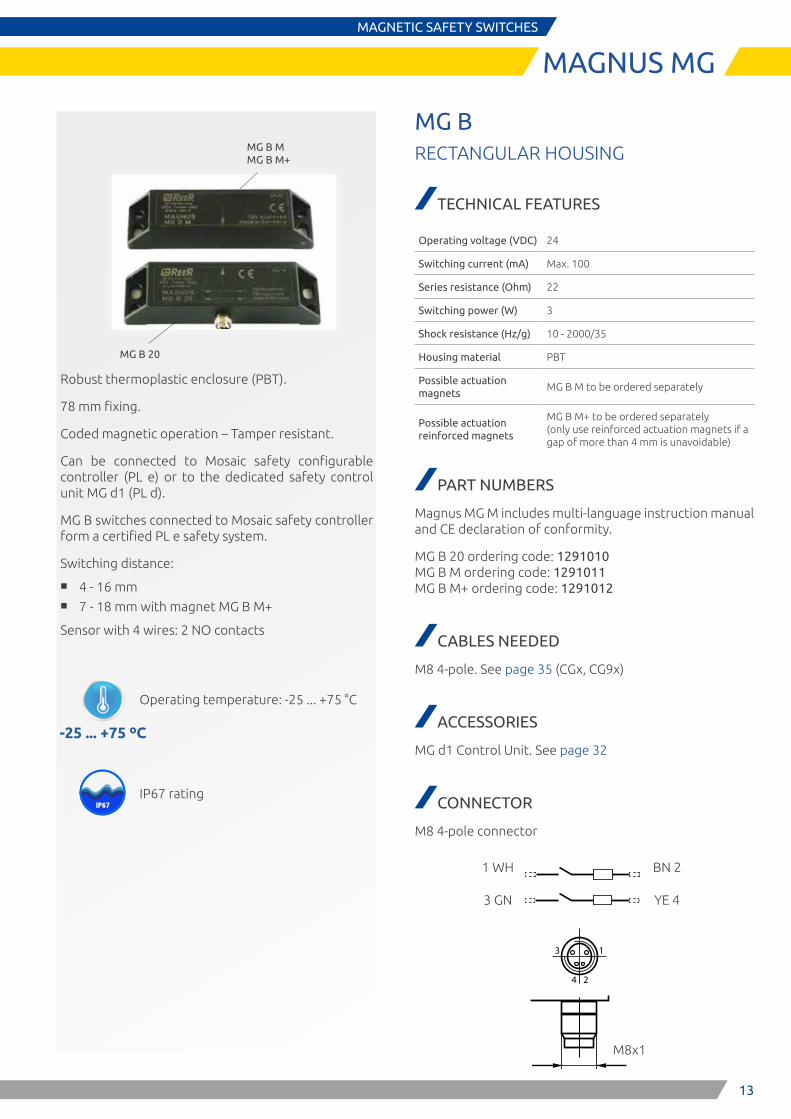
MG B M MG B M+
MG B 20
Robust thermoplastic enclosure (PBT).
78 mm fixing.
Coded magnetic operation – Tamper resistant.
Can be connected to Mosaic safety configurable controller (PL e) or to the dedicated safety control unit MG d1 (PL d).
MG B switches connected to Mosaic safety controller form a certified PL e safety system.
Switching distance:
■ 4 - 16 mm ■ 7 - 18 mm with magnet MG B M+
Sensor with 4 wires: 2 NO contacts
MG BRECTANGULAR HOUSING
TECHNICAL FEATURES
Operating voltage (VDC) 24
Switching current (mA) Max. 100
Series resistance (Ohm) 22
Switching power (W) 3
Shock resistance (Hz/g) 10 - 2000/35
Housing material PBT
Possible actuation magnets
MG B M to be ordered separately
Possible actuation reinforced magnets
MG B M+ to be ordered separately (only use reinforced actuation magnets if a gap of more than 4 mm is unavoidable)
PART NUMBERS
Magnus MG M includes multi-language instruction manual and CE declaration of conformity.
MG B 20 ordering code: 1291010 MG B M ordering code: 1291011 MG B M+ ordering code: 1291012
CABLES NEEDED
M8 4-pole. See page 35 (CGx, CG9x)
ACCESSORIES
MG d1 Control Unit. See page 32
CONNECTOR
M8 4-pole connector
-25 ... +75 ºC
IP67IP65
Operating temperature: -25 ... +75 °C
IP67 rating
3 1
4 2
1 WH
3 GN
BN 2
YE 4
M8x1
14
MAGNUS MGMAGNETIC SAFETY SWITCHES
APPROVALS
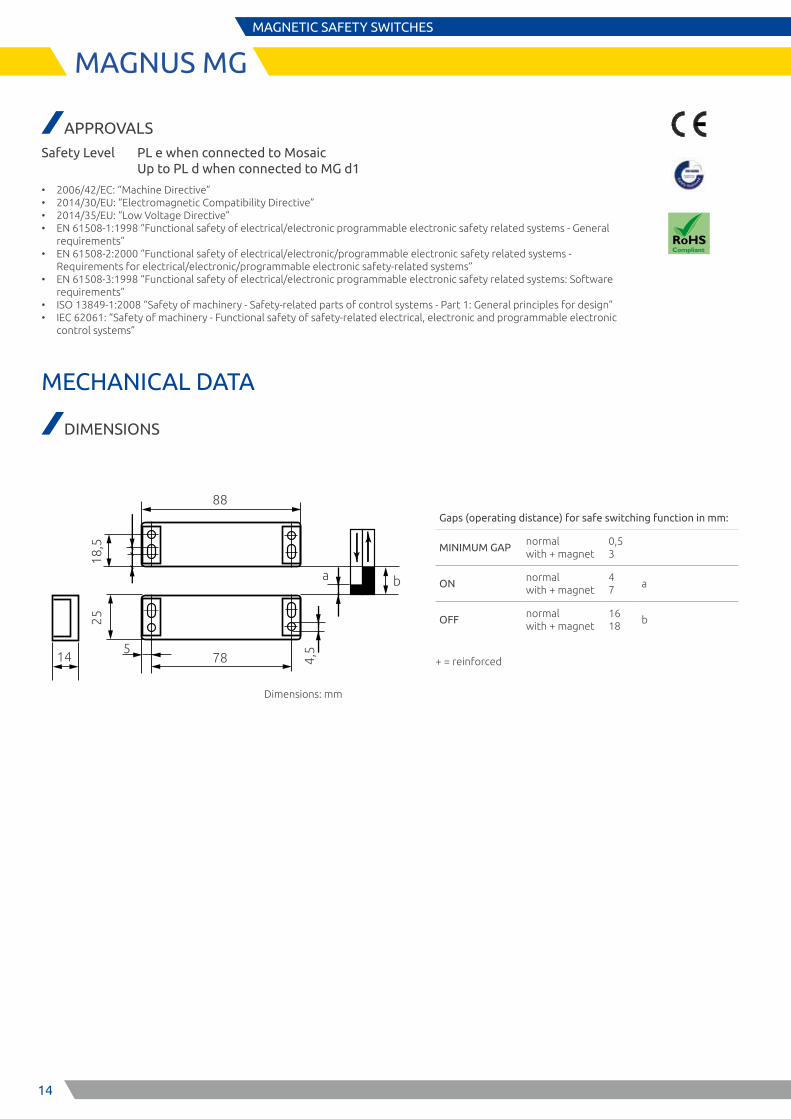
Safety Level PL e when connected to Mosaic Up to PL d when connected to MG d1
• 2006/42/EC: “Machine Directive” • 2014/30/EU: “Electromagnetic Compatibility Directive” • 2014/35/EU: “Low Voltage Directive” • EN 61508-1:1998 “Functional safety of electrical/electronic programmable electronic safety related systems - General
requirements” • EN 61508-2:2000 “Functional safety of electrical/electronic/programmable electronic safety related systems -
Requirements for electrical/electronic/programmable electronic safety-related systems” • EN 61508-3:1998 “Functional safety of electrical/electronic programmable electronic safety related systems: Software
requirements” • ISO 13849-1:2008 “Safety of machinery - Safety-related parts of control systems - Part 1: General principles for design” • IEC 62061: “Safety of machinery - Functional safety of safety-related electrical, electronic and programmable electronic
control systems”
MECHANICAL DATA
DIMENSIONS
Gaps (operating distance) for safe switching function in mm:
MINIMUM GAPnormal with + magnet
0,5 3
ONnormal with + magnet
4 7
a
OFFnormal with + magnet
16 18
b
+ = reinforced
Dimensions: mm
88
18,5
4,5
78
a b
14
25
5
15
MAGNUS MGMAGNETIC SAFETY SWITCHES
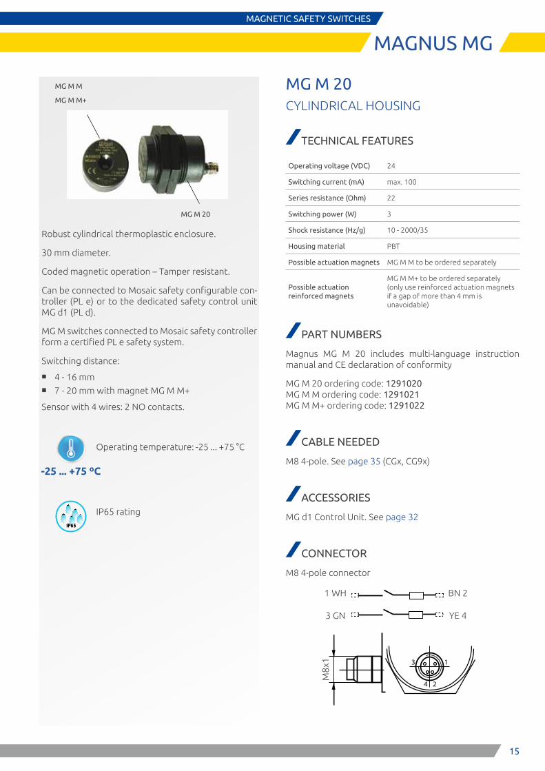
MG M 20
MG M M
MG M M+
Robust cylindrical thermoplastic enclosure.
30 mm diameter.
Coded magnetic operation – Tamper resistant.
Can be connected to Mosaic safety configurable con-troller (PL e) or to the dedicated safety control unit MG d1 (PL d).
MG M switches connected to Mosaic safety controller form a certified PL e safety system.
Switching distance:
■ 4 - 16 mm ■ 7 - 20 mm with magnet MG M M+
Sensor with 4 wires: 2 NO contacts.
-25 ... +75 ºC
IP67IP65
Operating temperature: -25 ... +75 °C
IP65 rating
MG M 20CYLINDRICAL HOUSING
TECHNICAL FEATURES
Operating voltage (VDC) 24
Switching current (mA) max. 100
Series resistance (Ohm) 22
Switching power (W) 3
Shock resistance (Hz/g) 10 - 2000/35
Housing material PBT
Possible actuation magnets MG M M to be ordered separately
Possible actuation reinforced magnets
MG M M+ to be ordered separately (only use reinforced actuation magnets if a gap of more than 4 mm is unavoidable)
PART NUMBERS
Magnus MG M 20 includes multi-language instruction manual and CE declaration of conformity
MG M 20 ordering code: 1291020 MG M M ordering code: 1291021 MG M M+ ordering code: 1291022
CABLE NEEDED
M8 4-pole. See page 35 (CGx, CG9x)
ACCESSORIES
MG d1 Control Unit. See page 32
CONNECTOR
M8 4-pole connector
3 1
4 2
1 WH
3 GN
BN 2
YE 4
M8x
1
16
MAGNUS MGMAGNETIC SAFETY SWITCHES
APPROVALS
Safety Level PL e when connected to Mosaic Up to PL d when connected to MG d1
• 2006/42/EC: “Machine Directive” • 2014/30/EU: “Electromagnetic Compatibility Directive” • 2014/35/EU: “Low Voltage Directive” • EN 61508-1:1998 “Functional safety of electrical/electronic programmable electronic safety related systems - General
requirements” • EN 61508-2:2000 “Functional safety of electrical/electronic/programmable electronic safety related systems -
Requirements for electrical/electronic/programmable electronic safety-related systems” • EN 61508-3:1998 “Functional safety of electrical/electronic programmable electronic safety related systems: Software
requirements” • ISO 13849-1:2008 “Safety of machinery - Safety-related parts of control systems - Part 1: General principles for design” • IEC 62061: “Safety of machinery - Functional safety of safety-related electrical, electronic and programmable electronic
control systems”
MECHANICAL DATA
DIMENSIONS
Gaps (operating distance) for safe switching function in mm:
MINIMUM GAPnormal with + magnet
0,5 3
ONnormal with + magnet
4 7
a
OFFnormal with + magnet
16 18
b
+ = reinforced
Dimensions: mm
36
M30
X1,
5
SW 36 a
b
28
6
3016
30
5,5
17
TYPE 3 SAFETY LASER SCANNER
PHARO
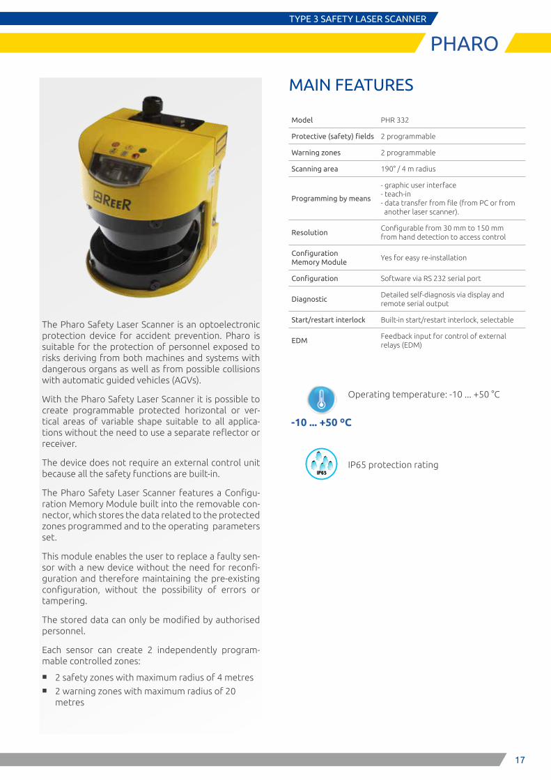
The Pharo Safety Laser Scanner is an optoelectronic protection device for accident prevention. Pharo is suitable for the protection of personnel exposed to risks deriving from both machines and systems with dangerous organs as well as from possible collisions with automatic guided vehicles (AGVs).
With the Pharo Safety Laser Scanner it is possible to create programmable protected horizontal or ver-tical areas of variable shape suitable to all applica-tions without the need to use a separate reflector or receiver.
The device does not require an external control unit because all the safety functions are built-in.
The Pharo Safety Laser Scanner features a Configu-ration Memory Module built into the removable con-nector, which stores the data related to the protected zones programmed and to the operating parameters set.
This module enables the user to replace a faulty sen-sor with a new device without the need for reconfi-guration and therefore maintaining the pre-existing configuration, without the possibility of errors or tampering.
The stored data can only be modified by authorised personnel.
Each sensor can create 2 independently program-mable controlled zones:
■ 2 safety zones with maximum radius of 4 metres ■ 2 warning zones with maximum radius of 20
metres
MAIN FEATURES
Model PHR 332
Protective (safety) fields 2 programmable
Warning zones 2 programmable
Scanning area 190° / 4 m radius
Programming by means
- graphic user interface - teach-in - data transfer from file (from PC or from another laser scanner).
ResolutionConfigurable from 30 mm to 150 mm from hand detection to access control
Configuration Memory Module
Yes for easy re-installation
Configuration Software via RS 232 serial port
DiagnosticDetailed self-diagnosis via display and remote serial output
Start/restart interlock Built-in start/restart interlock, selectable
EDMFeedback input for control of external relays (EDM)
-10 ... +50 ºC
IP67IP65
Operating temperature: -10 ... +50 °C
IP65 protection rating
18
SAFETY LEVEL
SIL 2 - SILCL 2PL d - Cat. 3
TYPE 3
E S P E
Optical windows section
M8x9
5535 53
,278
,5
185
160
93
65,227,8
13,5
23
63
77,5
155
211
TYPE 3 SAFETY LASER SCANNER
PHARO
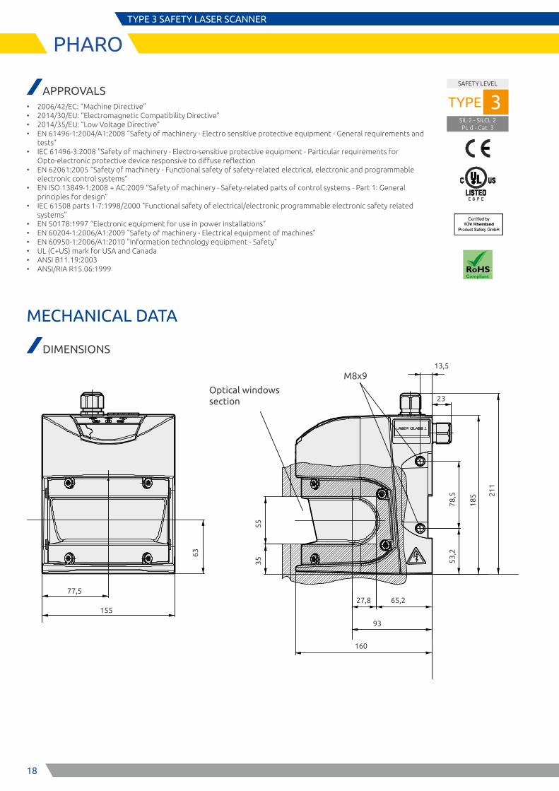
APPROVALS • 2006/42/EC: “Machine Directive” • 2014/30/EU: “Electromagnetic Compatibility Directive” • 2014/35/EU: “Low Voltage Directive” • EN 61496-1:2004/A1:2008 “Safety of machinery - Electro sensitive protective equipment - General requirements and
tests” • IEC 61496-3:2008 "Safety of machinery - Electro-sensitive protective equipment - Particular requirements for
Opto-electronic protective device responsive to diffuse reflection • EN 62061:2005 “Safety of machinery - Functional safety of safety-related electrical, electronic and programmable
electronic control systems” • EN ISO 13849-1:2008 + AC:2009 “Safety of machinery - Safety-related parts of control systems - Part 1: General
principles for design” • IEC 61508 parts 1-7:1998/2000 "Functional safety of electrical/electronic programmable electronic safety related
systems" • EN 50178:1997 “Electronic equipment for use in power installations” • EN 60204-1:2006/A1:2009 "Safety of machinery - Electrical equipment of machines" • EN 60950-1:2006/A1:2010 "Information technology equipment - Safety" • UL (C+US) mark for USA and Canada • ANSI B11.19:2003 • ANSI/RIA R15.06:1999
MECHANICAL DATA
DIMENSIONS
19
TYPE 3 SAFETY LASER SCANNER
PHARO
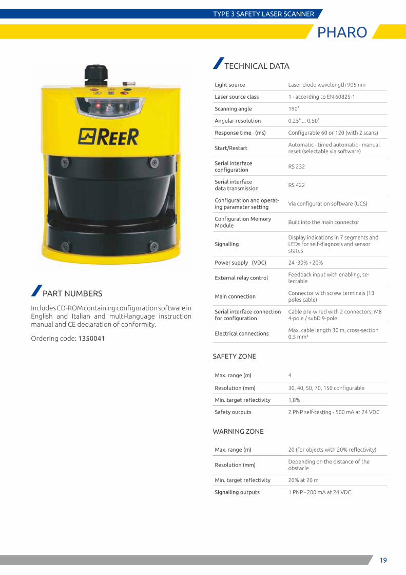
PART NUMBERS
Includes CD-ROM containing configuration software in English and Italian and multi-language instruction manual and CE declaration of conformity.
Ordering code: 1350041
TECHNICAL DATA
Light source Laser diode wavelength 905 nm
Laser source class 1 - according to EN 60825-1
Scanning angle 190°
Angular resolution 0,25° ... 0,50°
Response time (ms) Configurable 60 or 120 (with 2 scans)
Start/RestartAutomatic - timed automatic - manual reset (selectable via software)
Serial interface configuration
RS 232
Serial interface data transmission
RS 422
Configuration and operat-ing parameter setting
Via configuration software (UCS)
Configuration Memory Module
Built into the main connector
SignallingDisplay indications in 7 segments and LEDs for self-diagnosis and sensor status
Power supply (VDC) 24 -30% +20%
External relay controlFeedback input with enabling, se-lectable
Main connectionConnector with screw terminals (13 poles cable)
Serial interface connection for configuration
Cable pre-wired with 2 connectors: M8 4-pole / subD 9-pole
Electrical connectionsMax. cable length 30 m, cross-section 0.5 mm²
SAFETY ZONE
Max. range (m) 4
Resolution (mm) 30, 40, 50, 70, 150 configurable
Min. target reflectivity 1,8%
Safety outputs 2 PNP self-testing - 500 mA at 24 VDC
WARNING ZONE
Max. range (m) 20 (for objects with 20% reflectivity)
Resolution (mm)Depending on the distance of the obstacle
Min. target reflectivity 20% at 20 m
Signalling outputs 1 PNP - 200 mA at 24 VDC
20
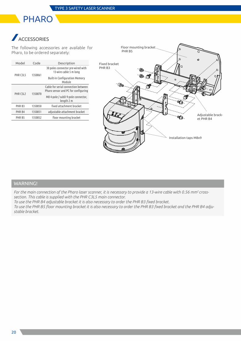
Floor mounting bracket PHR B5
Adjustable brack-et PHR B4
Fixed bracket PHR B3
Installation taps M8x9
TYPE 3 SAFETY LASER SCANNER
PHARO
ACCESSORIES
The following accessories are available for Pharo, to be ordered separately:
Model Code Description
PHR C3L5 1350061
30 poles connector pre-wired with 13-wire cable 5 m long
Built-in Configuration Memory Module
PHR CSL2 1350070
Cable for serial connection between Pharo sensor and PC for configuring
M8 4-pole / subD 9-pole connector, length 2 m
PHR B3 1350050 fixed attachment bracket
PHR B4 1350051 adjustable attachment bracket
PHR B5 1350052 floor mounting bracket
WARNING!
For the main connection of the Pharo laser scanner, it is necessary to provide a 13-wire cable with 0.56 mm2 cross-section. This cable is supplied with the PHR C3L5 main connector. To use the PHR B4 adjustable bracket it is also necessary to order the PHR B3 fixed bracket. To use the PHR B5 floor mounting bracket it is also necessary to order the PHR B3 fixed bracket and the PHR B4 adju-stable bracket.
21
TYPE 2 SINGLE-BEAM SAFETY PHOTOCELLS
ILION
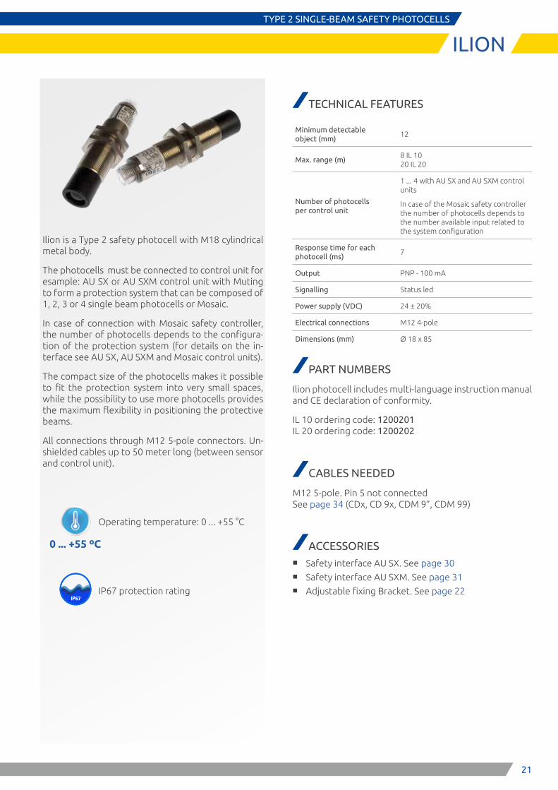
Ilion is a Type 2 safety photocell with M18 cylindrical metal body.
The photocells must be connected to control unit for esample: AU SX or AU SXM control unit with Muting to form a protection system that can be composed of 1, 2, 3 or 4 single beam photocells or Mosaic.
In case of connection with Mosaic safety controller, the number of photocells depends to the configura-tion of the protection system (for details on the in-terface see AU SX, AU SXM and Mosaic control units).
The compact size of the photocells makes it possible to fit the protection system into very small spaces, while the possibility to use more photocells provides the maximum flexibility in positioning the protective beams.
All connections through M12 5-pole connectors. Un-shielded cables up to 50 meter long (between sensor and control unit).
TECHNICAL FEATURES
Minimum detectable object (mm)
12
Max. range (m)8 IL 10 20 IL 20
Number of photocells per control unit
1 ... 4 with AU SX and AU SXM control units
In case of the Mosaic safety controller the number of photocells depends to the number available input related to the system configuration
Response time for each photocell (ms)
7
Output PNP - 100 mA
Signalling Status led
Power supply (VDC) 24 ± 20%
Electrical connections M12 4-pole
Dimensions (mm) Ø 18 x 85
PART NUMBERS
Ilion photocell includes multi-language instruction manual and CE declaration of conformity.
IL 10 ordering code: 1200201 IL 20 ordering code: 1200202
CABLES NEEDED
M12 5-pole. Pin 5 not connected See page 34 (CDx, CD 9x, CDM 9”, CDM 99)
ACCESSORIES ■ Safety interface AU SX. See page 30 ■ Safety interface AU SXM. See page 31 ■ Adjustable fixing Bracket. See page 22
0 ... +55 ºC
IP67IP65
Operating temperature: 0 ... +55 °C
IP67 protection rating
22
SAFETY LEVEL
SILCL 1PL c - Cat. 2
TYPE 2
TYPE 2 SINGLE-BEAM SAFETY PHOTOCELLS
ILION
APPROVALS
Safety level (with a control unit AU XS, AU SXM or Mosaic): Type 2 – SIL CL 1 – PL c – Cat. 2
• 2006/42/EC: “Machine Directive” • 2014/30/EU: “Electromagnetic Compatibility Directive” • 2014/35/EU: “Low Voltage Directive” • IEC 61496-1 (ed.3) “Safety of machinery - Electro sensitive protective equipment - General requirements and tests” • IEC 61496-2 (ed.3) “Safety of machinery - Electro-sensitive protective equipment - Particular requirements for equipment
using active opto-electronic protective devices (AOPDs)" • ISO 13849-1:2006 “Safety of machinery - Safety-related parts of control systems - Part 1: General principles for design” • IEC 62061 (ed.1) “Safety of machinery - Functional safety of safety-related electrical, electronic and programmable
electronic control systems” • EN 50178:1997 “Electronic equipment for use in power installations” • EN 55022:2110 “Information Technology Equipment - Radio Disturbance Characteristics - Limits and Methods of
Measurement”
MECHANICAL DATA
DIMENSIONS
Dimensions: mm
86
60
43
M12
9
M18
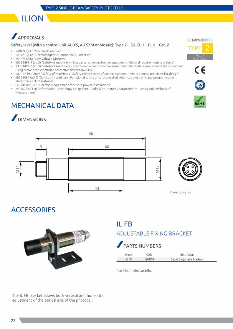
The IL FB bracket allows both vertical and horizontal adjustment of the optical axis of the photocell.
IL FBADJUSTABLE FIXING BRACKET
PARTS NUMBERS
Model Code Description
IL FB 1200090 Set of 2 adjustable brackets
For Illion photocells.
ACCESSORIES
23
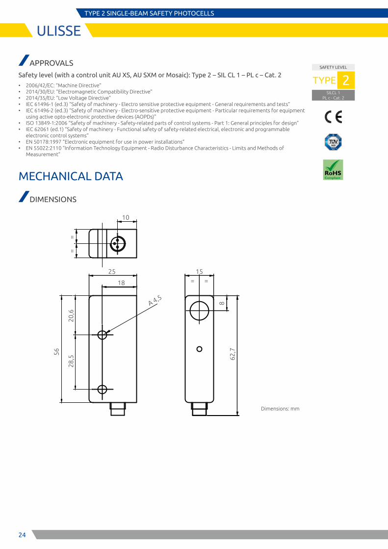
ULISSETYPE 2 SINGLE-BEAM SAFETY PHOTOCELLS
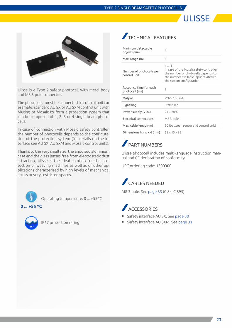
Ulisse is a Type 2 safety photocell with metal body and M8 3-pole connector.
The photocells must be connected to control unit for esample: standard AU SX or AU SXM control unit with Muting or Mosaic to form a protection system that can be composed of 1, 2, 3 or 4 single beam photo-cells.
In case of connection with Mosaic safety controller, the number of photocells depends to the configura-tion of the protection system (for details on the in-terface see AU SX, AU SXM and Mosaic control units).
Thanks to the very small size, the anodised aluminium case and the glass lenses free from electrostatic dust attraction, Ulisse is the ideal solution for the pro-tection of weaving machines as well as of other ap-plications characterised by high levels of mechanical stress or very restricted spaces.
0 ... +55 ºC
IP67IP65
Operating temperature: 0 ... +55 °C
IP67 protection rating
TECHNICAL FEATURES
Minimum detectable object (mm)
8
Max. range (m) 6
Number of photocells per control unit
1 ... 4 In case of the Mosaic safety controller the number of photocells depends to the number available input related to the system configuration
Response time for each photocell (ms)
7
Output PNP - 100 mA
Signalling Status led
Power supply (VDC) 24 ± 20%
Electrical connections M8 3-pole
Max. cable length (m) 50 (between sensor and control unit)
Dimensions h x w x d (mm) 58 x 15 x 25
PART NUMBERS
Ulisse photocell includes multi-language instruction man-ual and CE declaration of conformity.
UPC ordering code: 1200300
CABLES NEEDED
M8 3-pole. See page 35 (C 8x, C 895)
ACCESSORIES ■ Safety interface AU SX. See page 30 ■ Safety interface AU SXM. See page 31
24
SAFETY LEVEL
SILCL 1PL c - Cat. 2
TYPE 2
ULISSETYPE 2 SINGLE-BEAM SAFETY PHOTOCELLS
APPROVALS
Safety level (with a control unit AU XS, AU SXM or Mosaic): Type 2 – SIL CL 1 – PL c – Cat. 2
• 2006/42/EC: “Machine Directive” • 2014/30/EU: “Electromagnetic Compatibility Directive” • 2014/35/EU: “Low Voltage Directive” • IEC 61496-1 (ed.3) “Safety of machinery - Electro sensitive protective equipment - General requirements and tests” • IEC 61496-2 (ed.3) “Safety of machinery - Electro-sensitive protective equipment - Particular requirements for equipment
using active opto-electronic protective devices (AOPDs)" • ISO 13849-1:2006 “Safety of machinery - Safety-related parts of control systems - Part 1: General principles for design” • IEC 62061 (ed.1) “Safety of machinery - Functional safety of safety-related electrical, electronic and programmable
electronic control systems” • EN 50178:1997 “Electronic equipment for use in power installations” • EN 55022:2110 “Information Technology Equipment - Radio Disturbance Characteristics - Limits and Methods of
Measurement”
MECHANICAL DATA
DIMENSIONS
Dimensions: mm
10
56
25
18
15= =
==
20,6
28,5
8
62,7
A 4,5
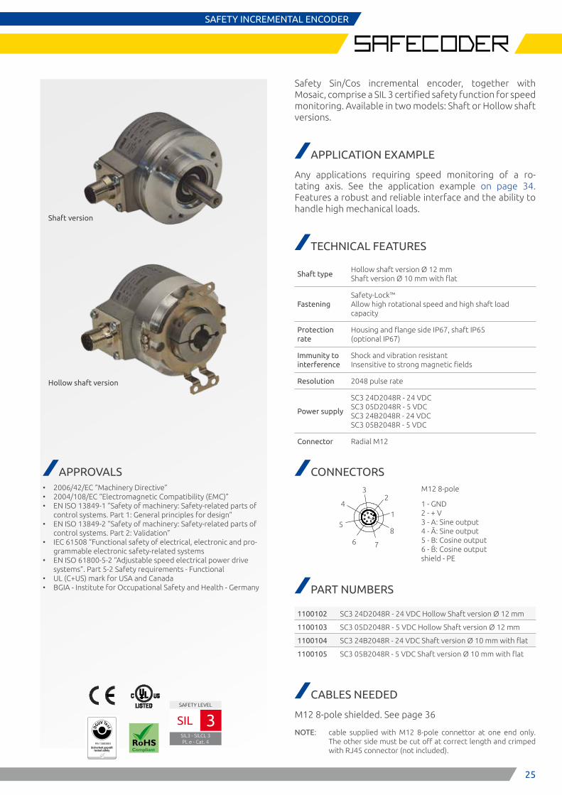
Shaft version
Hollow shaft version
APPROVALS • 2006/42/EC “Machinery Directive” • 2004/108/EC “Electromagnetic Compatibility (EMC)” • EN ISO 13849-1 “Safety of machinery: Safety-related parts of
control systems. Part 1: General principles for design” • EN ISO 13849-2 “Safety of machinery: Safety-related parts of
control systems. Part 2: Validation” • IEC 61508 “Functional safety of electrical, electronic and pro-
grammable electronic safety-related systems • EN ISO 61800-5-2 “Adjustable speed electrical power drive
systems”. Part 5-2 Safety requirements - Functional • UL (C+US) mark for USA and Canada • BGIA - Institute for Occupational Safety and Health - Germany
E S P E
IFA 13003003
SAFETY LEVEL
SIL3 - SILCL 3PL e - Cat. 4
SIL 3
25
42
3
15
6 7
8
M12 8-pole
1 - GND 2 - + V 3 - A: Sine output 4 - Ā: Sine output 5 - B: Cosine output 6 - B: Cosine output shield - PE
SAFETY INCREMENTAL ENCODER
Safety Sin/Cos incremental encoder, together with Mosaic, comprise a SIL 3 certified safety function for speed monitoring. Available in two models: Shaft or Hollow shaft versions.
APPLICATION EXAMPLE
Any applications requiring speed monitoring of a ro-tating axis. See the application example on page 34. Features a robust and reliable interface and the ability to handle high mechanical loads.
TECHNICAL FEATURES
Shaft typeHollow shaft version Ø 12 mm Shaft version Ø 10 mm with flat
FasteningSafety-Lock™ Allow high rotational speed and high shaft load capacity
Protection rate
Housing and flange side IP67, shaft IP65 (optional IP67)
Immunity to interference
Shock and vibration resistant Insensitive to strong magnetic fields
Resolution 2048 pulse rate
Power supply
SC3 24D2048R - 24 VDC SC3 05D2048R - 5 VDC SC3 24B2048R - 24 VDC SC3 05B2048R - 5 VDC
Connector Radial M12
CONNECTORS
PART NUMBERS
1100102 SC3 24D2048R - 24 VDC Hollow Shaft version Ø 12 mm
1100103 SC3 05D2048R - 5 VDC Hollow Shaft version Ø 12 mm
1100104 SC3 24B2048R - 24 VDC Shaft version Ø 10 mm with flat
1100105 SC3 05B2048R - 5 VDC Shaft version Ø 10 mm with flat
CABLES NEEDED
M12 8-pole shielded. See page 36
NOTE: cable supplied with M12 8-pole connettor at one end only. The other side must be cut off at correct length and crimped with RJ45 connector (not included).
26
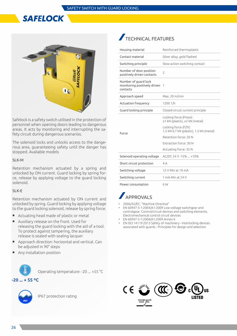
SAFETY SWITCH WITH GUARD LOCKING
Safelock is a safety switch utilised in the protection of personnel when opening doors leading to dangerous areas. It acts by monitoring and interrupting the sa-fety circuit during dangerous scenarios.
The solenoid locks and unlocks access to the dange-rous area, guaranteeing safety until the danger has stopped. Available models
SLK-M
Retention mechanism actuated by a spring and unlocked by ON current. Guard locking by spring for-ce, release by applying voltage to the guard locking solenoid.
SLK-E
Retention mechanism actuated by ON current and unlocked by spring. Guard locking by applying voltage to the guard locking solenoid, release by spring force.
■ Actuating head made of plastic or metal ■ Auxiliary release on the front. Used for
releasing the guard locking with the aid of a tool. To protect against tampering, the auxiliary release is sealed with sealing lacquer
■ Approach direction: horizontal and vertical. Can be adjusted in 90° steps
■ Any installation position
-20 ... + 55 ºC
IP67IP65
Operating temperature: -20 ... +55 °C
IP67 protection rating
TECHNICAL FEATURES
Housing material Reinforced thermoplastic
Contact material Silver alloy, gold flashed
Switching principle Slow-action switching contact
Number of door position positively driven contacts
2
Number of guard lock monitoring positively driven contacts
1
Approach speed Max. 20 m/min
Actuation frequency 1200 1/h
Guard locking principle Closed-circuit current principle
Force
Locking force (Fmax): ≥1 kN (plastic), ≥2 kN (metal)
Locking force (FZh): 1,5 kN 0,7 kN (plastic), 1,5 kN (metal)
Retention force: 20 N
Extraction force: 30 N
Actuating force: 35 N
Solenoid operating voltage AC/DC 24 V -15% ... +10%
Short circuit protection 4 A
Switching voltage 12 V Min at 10 mA
Switching current 1 mA Min at 24 V
Power consumption 6 W
APPROVALS • 2006/42/EC: “Machine Directive” • EN 60947-5-1:2004/A1:2009 Low-voltage switchgear and
controlgear. Control/circuit devices and switching elements. Electromechanical control circuit devices
• EN 60947-5-1:2004/A1:2009 Annex K • EN ISO 14119:2013 Safety of machinery - Interlocking devices
associated with guards - Principles for design and selection
27
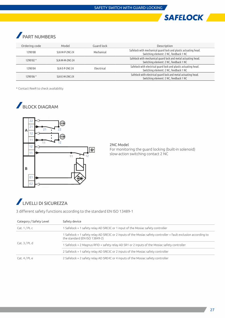
SAFETY SWITCH WITH GUARD LOCKING
2NC Model For monitoring the guard locking (built-in solenoid) slow-action switching contact 2 NC
B
A
22
21
12
11
12
11
E1
E2
21 22
11 12
11 12
PART NUMBERS
Ordering code Model Guard lock Description
1290100 SLK-M-P-2NC-24 MechanicalSafelock with mechanical guard lock and plastic actuating head.
Switching element: 2 NC, feedback 1 NC
1290102 * SLK-M-M-2NC-24Safelock with mechanical guard lock and metal actuating head.
Switching element: 2 NC, feedback 1 NC
1290104 SLK-E-P-2NC-24 ElecrtricalSafelock with electrical guard lock and plastic actuating head.
Switching element: 2 NC, feedback 1 NC
1290106 * SLK-E-M-2NC-24Safelock with electrical guard lock and metal actuating head.
Switching element: 2 NC, feedback 1 NC
* Contact ReeR to check availability
BLOCK DIAGRAM
LIVELLI DI SICUREZZA
3 different safety functions according to the standard EN ISO 13489-1
Category / Safety Level Safety device
Cat. 1 / PL c 1 Safelock + 1 safety relay AD SRE3C or 1 input of the Mosiac safety controller
Cat. 3 / PL d
1 Safelock + 1 safety relay AD SRE3C or 2 inputs of the Mosiac safety controller + fault exclusion according to the standard (EN ISO 13849-2)
1 Safelock + 2 Magnus RFID + safety relay AD SR1 or 2 inputs of the Mosiac safety controller
2 Safelock + 1 safety relay AD SRE3C or 2 inputs of the Mosiac safety controller
Cat. 4 / PL e 2 Safelock + 2 safety relay AD SRE4C or 4 inputs of the Mosiac safety controller
28
SAFETY SWITCH WITH GUARD LOCKINGSAFETY SWITCH WITH GURD LOCKING
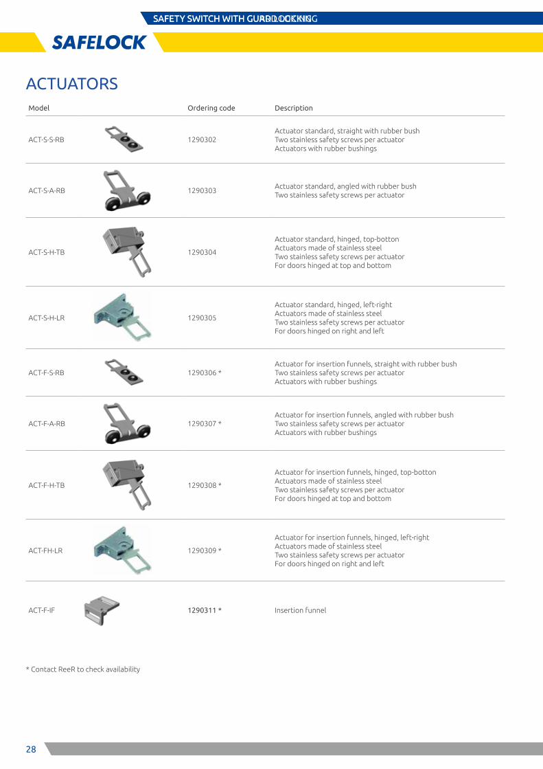
ACTUATORSModel Ordering code Description
ACT-S-S-RB 1290302Actuator standard, straight with rubber bush Two stainless safety screws per actuator Actuators with rubber bushings
ACT-S-A-RB 1290303Actuator standard, angled with rubber bush Two stainless safety screws per actuator
ACT-S-H-TB 1290304
Actuator standard, hinged, top-botton Actuators made of stainless steel Two stainless safety screws per actuator For doors hinged at top and bottom
ACT-S-H-LR 1290305
Actuator standard, hinged, left-right Actuators made of stainless steel Two stainless safety screws per actuator For doors hinged on right and left
ACT-F-S-RB 1290306 *Actuator for insertion funnels, straight with rubber bush Two stainless safety screws per actuator Actuators with rubber bushings
ACT-F-A-RB 1290307 *Actuator for insertion funnels, angled with rubber bush Two stainless safety screws per actuator Actuators with rubber bushings
ACT-F-H-TB 1290308 *
Actuator for insertion funnels, hinged, top-botton Actuators made of stainless steel Two stainless safety screws per actuator For doors hinged at top and bottom
ACT-FH-LR 1290309 *
Actuator for insertion funnels, hinged, left-right Actuators made of stainless steel Two stainless safety screws per actuator For doors hinged on right and left
ACT-F-IF 1290311 * Insertion funnel
* Contact ReeR to check availability
29
SAFETY SWITCH WITH GUARD LOCKING
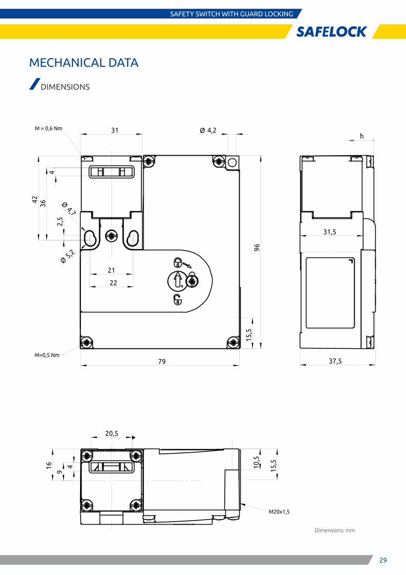
MECHANICAL DATA
DIMENSIONS
Dimensions: mm
31
2,5
Ø4,7
79
15,5
22
21Ø
5,2
Ø 4,2
96
42 364
M=0,5 Nm
M = 0,6 Nm
16
9 15,5
10,5
4
20,5
M20x1,5
37,5
31,5
h
3030
ACCESSORIES
INTERFACES
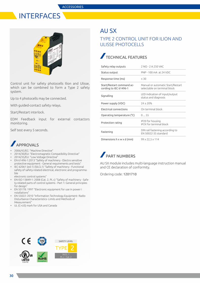
Control unit for safety photocells Ilion and Ulisse, which can be combined to form a Type 2 safety system.
Up to 4 photocells may be connected.
With guided-contact safety relays.
Start/Restart interlock.
EDM Feedback input for external contactors monitoring.
Self test every 5 seconds.
APPROVALS • 2006/42/EC: “Machine Directive” • 2014/30/EU: “Electromagnetic Compatibility Directive” • 2014/35/EU: “Low Voltage Directive” • EN 61496-1:2013 “Safety of machinery - Electro sensitive
protective equipment - General requirements and tests” • IEC 62061 (ed.1) (SILCL1) “Safety of machinery - Functional
safety of safety-related electrical, electronic and programma-ble electronic control systems”
• EN ISO 13849-1: 2008 (Cat. 2, PL c) “Safety of machinery - Safe-ty-related parts of control systems - Part 1: General principles for design”
• EN 50178: 1997 “Electronic equipment for use in power i nstallations”
• EN 55022: 2010 “Information Technology Equipment- Radio Disturbance Characteristics- Limits and Methods of Measurement”
• UL (C+US) mark for USA and Canada
AU SXTYPE 2 CONTROL UNIT FOR ILION AND ULISSE PHOTOCELLS
TECHNICAL FEATURES
Safety relay outputs 2 NO - 2 A 250 VAC
Status output PNP - 100 mA at 24 VDC
Response time (ms) ≤ 30
Start/Restart command ac-cording to IEC 61496-1
Manual or automatic Start/Restart selectable on terminal block
SignallingLED indication of input/output status and diagnosis
Power supply (VDC) 24 ± 20%
Electrical connections On terminal block
Operating temperature (°C) 0 ... 55
Protection ratingIP20 for housing IP2X for terminal block
FasteningDIN rail fastening according to EN 50022-35 standard
Dimensions h x w x d (mm) 99 x 22,5 x 114
PART NUMBERS
AU SX module includes multi-language instruction manual and CE declaration of conformity.
Ordering code: 1201710
SAFETY LEVEL
SILCL 1PL c - Cat. 2
TYPE 2
E S P E
31
ACCESSORIES
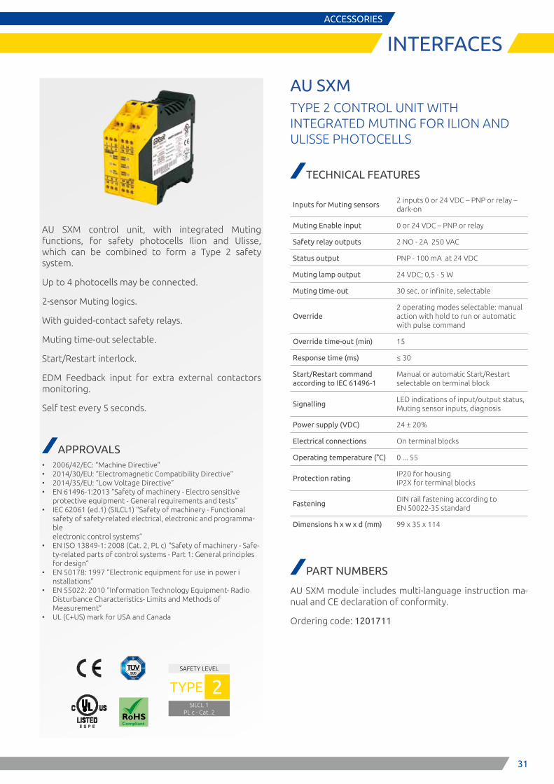
INTERFACES
AU SXM control unit, with integrated Muting functions, for safety photocells Ilion and Ulisse, which can be combined to form a Type 2 safety system.
Up to 4 photocells may be connected.
2-sensor Muting logics.
With guided-contact safety relays.
Muting time-out selectable.
Start/Restart interlock.
EDM Feedback input for extra external contactors monitoring.
Self test every 5 seconds.
APPROVALS • 2006/42/EC: “Machine Directive” • 2014/30/EU: “Electromagnetic Compatibility Directive” • 2014/35/EU: “Low Voltage Directive” • EN 61496-1:2013 “Safety of machinery - Electro sensitive
protective equipment - General requirements and tests” • IEC 62061 (ed.1) (SILCL1) “Safety of machinery - Functional
safety of safety-related electrical, electronic and programma-ble electronic control systems”
• EN ISO 13849-1: 2008 (Cat. 2, PL c) “Safety of machinery - Safe-ty-related parts of control systems - Part 1: General principles for design”
• EN 50178: 1997 “Electronic equipment for use in power i nstallations”
• EN 55022: 2010 “Information Technology Equipment- Radio Disturbance Characteristics- Limits and Methods of Measurement”
• UL (C+US) mark for USA and Canada
SAFETY LEVEL
SILCL 1PL c - Cat. 2
TYPE 2
E S P E
AU SXMTYPE 2 CONTROL UNIT WITH INTEGRATED MUTING FOR ILION AND ULISSE PHOTOCELLS
TECHNICAL FEATURES
Inputs for Muting sensors2 inputs 0 or 24 VDC – PNP or relay – dark-on
Muting Enable input 0 or 24 VDC – PNP or relay
Safety relay outputs 2 NO - 2A 250 VAC
Status output PNP - 100 mA at 24 VDC
Muting lamp output 24 VDC; 0,5 - 5 W
Muting time-out 30 sec. or infinite, selectable
Override2 operating modes selectable: manual action with hold to run or automatic with pulse command
Override time-out (min) 15
Response time (ms) ≤ 30
Start/Restart command according to IEC 61496-1
Manual or automatic Start/Restart selectable on terminal block
SignallingLED indications of input/output status, Muting sensor inputs, diagnosis
Power supply (VDC) 24 ± 20%
Electrical connections On terminal blocks
Operating temperature (°C) 0 ... 55
Protection ratingIP20 for housing IP2X for terminal blocks
FasteningDIN rail fastening according to EN 50022-35 standard
Dimensions h x w x d (mm) 99 x 35 x 114
PART NUMBERS
AU SXM module includes multi-language instruction ma-nual and CE declaration of conformity.
Ordering code: 1201711
32
ACCESSORIES
INTERFACES
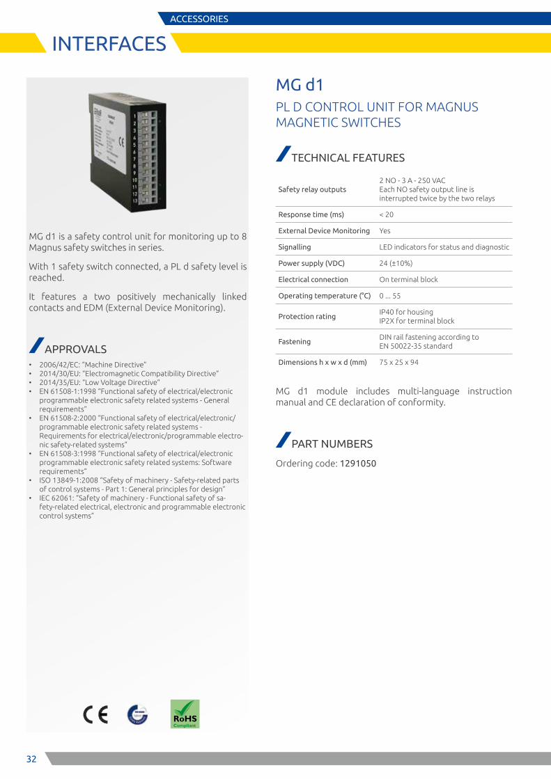
MG d1 is a safety control unit for monitoring up to 8 Magnus safety switches in series.
With 1 safety switch connected, a PL d safety level is reached.
It features a two positively mechanically linked contacts and EDM (External Device Monitoring).
APPROVALS • 2006/42/EC: “Machine Directive” • 2014/30/EU: “Electromagnetic Compatibility Directive” • 2014/35/EU: “Low Voltage Directive” • EN 61508-1:1998 “Functional safety of electrical/electronic
programmable electronic safety related systems - General requirements”
• EN 61508-2:2000 “Functional safety of electrical/electronic/programmable electronic safety related systems - Requirements for electrical/electronic/programmable electro-nic safety-related systems”
• EN 61508-3:1998 “Functional safety of electrical/electronic programmable electronic safety related systems: Software requirements”
• ISO 13849-1:2008 “Safety of machinery - Safety-related parts of control systems - Part 1: General principles for design”
• IEC 62061: “Safety of machinery - Functional safety of sa-fety-related electrical, electronic and programmable electronic control systems”
MG d1PL D CONTROL UNIT FOR MAGNUS MAGNETIC SWITCHES
TECHNICAL FEATURES
Safety relay outputs2 NO - 3 A - 250 VAC Each NO safety output line is interrupted twice by the two relays
Response time (ms) < 20
External Device Monitoring Yes
Signalling LED indicators for status and diagnostic
Power supply (VDC) 24 (±10%)
Electrical connection On terminal block
Operating temperature (°C) 0 ... 55
Protection ratingIP40 for housing IP2X for terminal block
FasteningDIN rail fastening according to EN 50022-35 standard
Dimensions h x w x d (mm) 75 x 25 x 94
MG d1 module includes multi-language instruction manual and CE declaration of conformity.
PART NUMBERS
Ordering code: 1291050
33
ACCESSORIES
CABLES
Ø 14,5
M 12x1
46
1 - Brown
2 - White
3 - Blue
4 - Black
5 - Grey
2
3
54
1
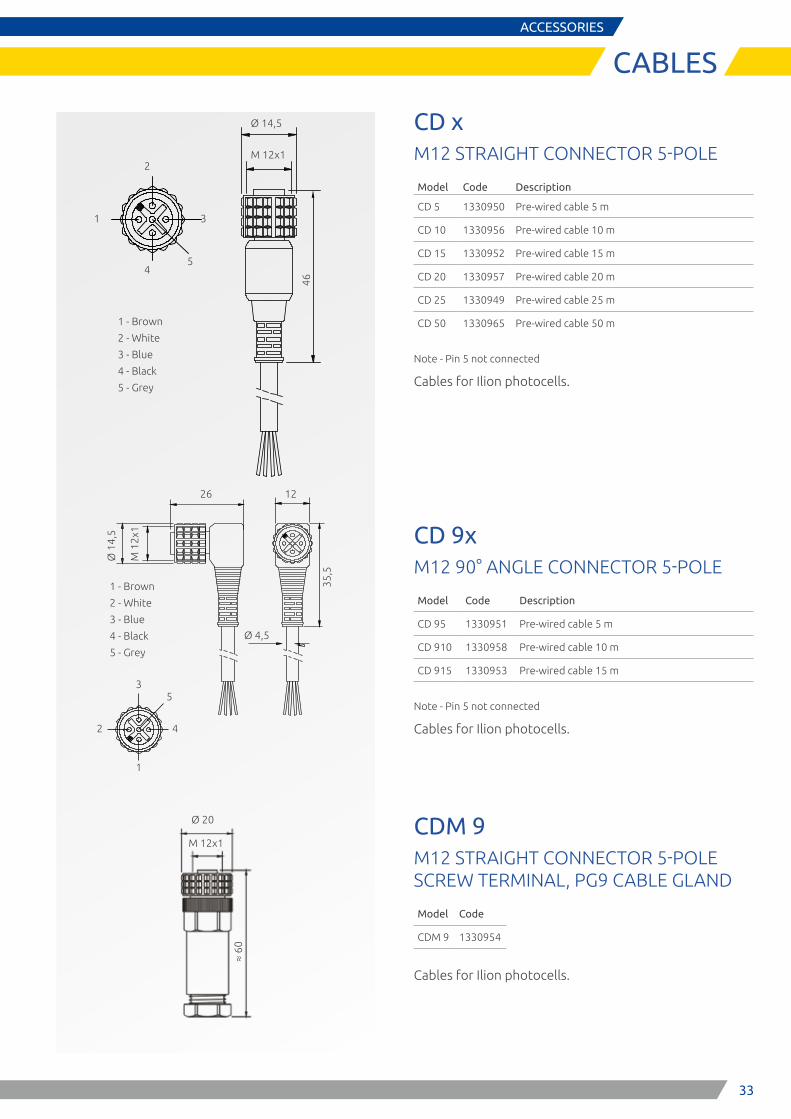
CD xM12 STRAIGHT CONNECTOR 5-POLE
Model Code Description
CD 5 1330950 Pre-wired cable 5 m
CD 10 1330956 Pre-wired cable 10 m
CD 15 1330952 Pre-wired cable 15 m
CD 20 1330957 Pre-wired cable 20 m
CD 25 1330949 Pre-wired cable 25 m
CD 50 1330965 Pre-wired cable 50 m
Note - Pin 5 not connected
Cables for Ilion photocells.
CD 9xM12 90° ANGLE CONNECTOR 5-POLE
Model Code Description
CD 95 1330951 Pre-wired cable 5 m
CD 910 1330958 Pre-wired cable 10 m
CD 915 1330953 Pre-wired cable 15 m
Note - Pin 5 not connected
Cables for Ilion photocells.
CDM 9M12 STRAIGHT CONNECTOR 5-POLE SCREW TERMINAL, PG9 CABLE GLAND
Model Code
CDM 9 1330954
Cables for Ilion photocells.
Ø 1
4,5
M 1
2x1
1 - Brown
2 - White
3 - Blue
4 - Black
5 - Grey
5
26 12
Ø 4,5
35,5
3
4
1
2
Ø 20
≈ 60
M 12x1
1
23
27
8,5
4
1 - Brown
2 - White
3 - Blue
4 - Black
M 8
16,5
Ø 10,5
Ø 4,5
34
M 8
12
3
1 - Brown
2 - White
3 - Blue
4 - Black
30
Ø 10
Ø 4,5
4
ACCESSORIES
CABLES
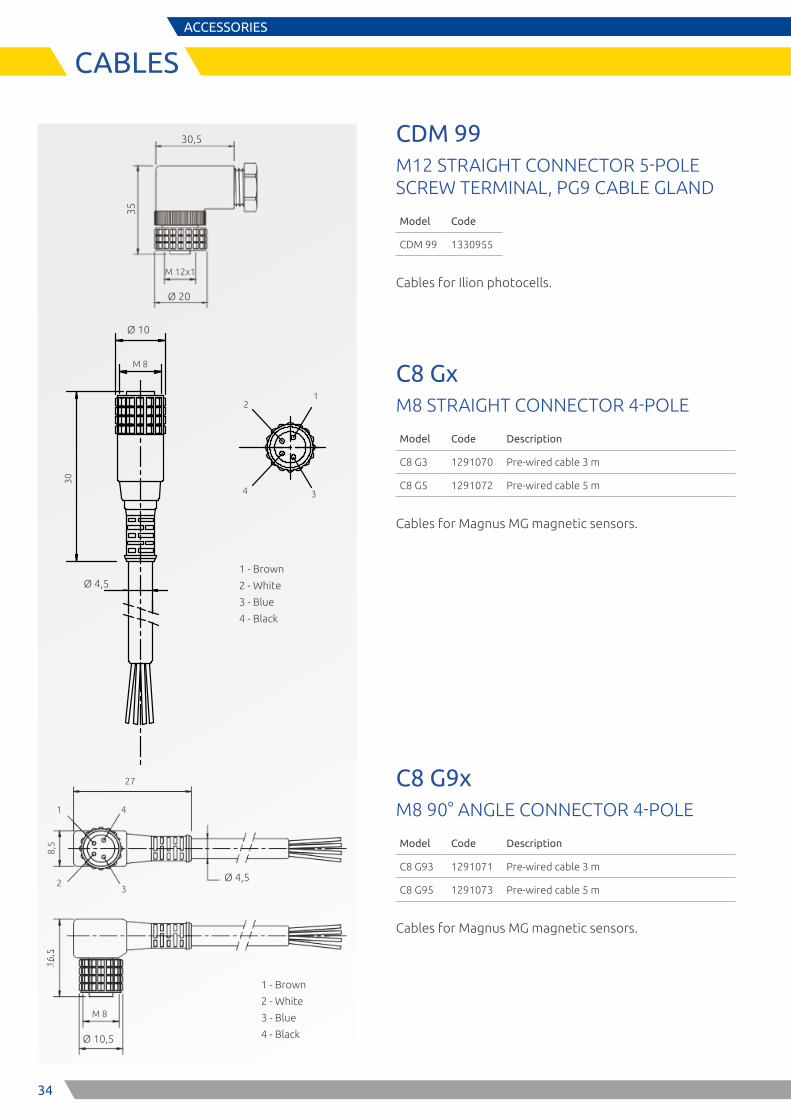
CDM 99M12 STRAIGHT CONNECTOR 5-POLE SCREW TERMINAL, PG9 CABLE GLAND
Model Code
CDM 99 1330955
Cables for Ilion photocells.
C8 GxM8 STRAIGHT CONNECTOR 4-POLE
Model Code Description
C8 G3 1291070 Pre-wired cable 3 m
C8 G5 1291072 Pre-wired cable 5 m
Cables for Magnus MG magnetic sensors.
C8 G9xM8 90° ANGLE CONNECTOR 4-POLE
Model Code Description
C8 G93 1291071 Pre-wired cable 3 m
C8 G95 1291073 Pre-wired cable 5 m
Cables for Magnus MG magnetic sensors.
35
M 12x1
30,5
Ø 20
35
ACCESSORIES
CABLES
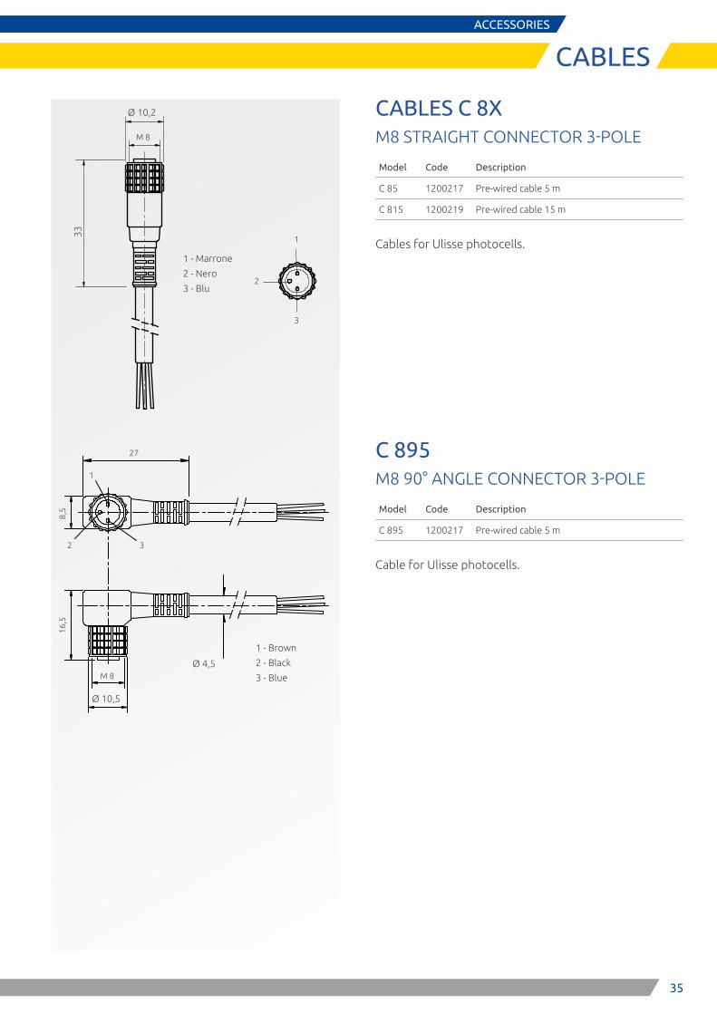
CABLES C 8XM8 STRAIGHT CONNECTOR 3-POLE
Model Code Description
C 85 1200217 Pre-wired cable 5 m
C 815 1200219 Pre-wired cable 15 m
Cables for Ulisse photocells.
C 895M8 90° ANGLE CONNECTOR 3-POLE
Model Code Description
C 895 1200217 Pre-wired cable 5 m
Cable for Ulisse photocells.
M 8
1
2 3
1 - Brown
2 - Black
3 - Blue
27
16,5
8,5
Ø 10,5
Ø 4,5
M 8
33
Ø 10,2
1
2
3
1 - Marrone
2 - Nero
3 - Blu
36
ACCESSORIES
CABLES
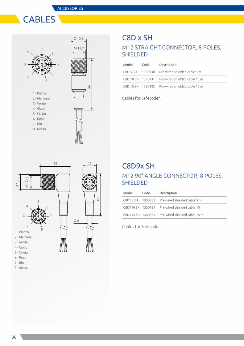
C8D x SHM12 STRAIGHT CONNECTOR, 8 POLES, SHIELDED
Model Code Description
C8D 5 SH 1330930 Pre-wired shielded cable 5 m
C8D 10 SH 1330931 Pre-wired shielded cable 10 m
C8D 15 SH 1330932 Pre-wired shielded cable 15 m
Cables for Safecoder.
C8D9x SHM12 90° ANGLE CONNECTOR, 8 POLES, SHIELDED
Model Code Description
C8D95 SH 1330933 Pre-wired shielded cable 5 m
C8D910 SX 1330934 Pre-wired shielded cable 10 m
C8D915 SH 1330935 Pre-wired shielded cable 15 m
Cables for Safecoder.
Ø 13,8
M 12x1
461 - Bianco
2 - Marrone
3 - Verde
4 - Giallo
5 - Grigio
6 - Rosa
7 - Blu
8 - Rosso
2
3
54
1
6
8
7
Ø 1
3,5
M 1
2x1
35,5
1 - Bianco
2 - Marrone
3 - Verde
4 - Giallo
5 - Grigio
6 - Rosa
7 - Blu
8 - Rosso
2
3
54
1
6
8
7Ø 6
26 12
37
ACCESSORIES
CABLES
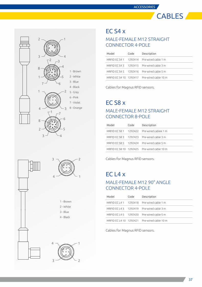
EC S4 xMALE-FEMALE M12 STRAIGHT CONNECTOR 4-POLE
Model Code Description
MRFID EC S4 1 1292414 Pre-wired cable 1 m
MRFID EC S4 3 1292415 Pre-wired cable 3 m
MRFID EC S4 5 1292416 Pre-wired cable 5 m
MRFID EC S4 10 1292417 Pre-wired cable 10 m
Cables for Magnus RFID sensors.
EC S8 xMALE-FEMALE M12 STRAIGHT CONNECTOR 8-POLE
Model Code Description
MRFID EC S8 1 1292422 Pre-wired cablee 1 m
MRFID EC S8 3 1292423 Pre-wired cable 3 m
MRFID EC S8 5 1292424 Pre-wired cable 5 m
MRFID EC S8 10 1292425 Pre-wired cable 10 m
Cables for Magnus RFID sensors.
EC L4 xMALE-FEMALE M12 90° ANGLE CONNECTOR 4-POLE
Model Code Description
MRFID EC L4 1 1292418 Pre-wired cable 1 m
MRFID EC L4 3 1292419 Pre-wired cable 3 m
MRFID EC L4 5 1292420 Pre-wired cable 5 m
MRFID EC L4 10 1292421 Pre-wired cable 10 m
Cables for Magnus RFID sensors.
1 - Brown
2 - White
3 - Blue
4 - Black
5 - Grey
6 - Pink
7 - Violet
8 - Orange
1
3
2
42 3
4
5
67
1
8
2
4
1
31 7
6
5
43
2
8
1 - Brown
2 - White
3 - Blue
4 - Black
2
4
3
1
1
3
4
2
38
A
48
8
B
8
4 4
C
2
43
ACCESSORIES
CABLES
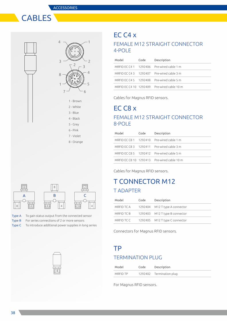
EC C4 xFEMALE M12 STRAIGHT CONNECTOR 4-POLE
Model Code Description
MRFID EC C4 1 1292406 Pre-wired cable 1 m
MRFID EC C4 3 1292407 Pre-wired cable 3 m
MRFID EC C4 5 1292408 Pre-wired cable 5 m
MRFID EC C4 10 1292409 Pre-wired cable 10 m
Cables for Magnus RFID sensors.
EC C8 xFEMALE M12 STRAIGHT CONNECTOR 8-POLE
Model Code Description
MRFID EC C8 1 1292410 Pre-wired cable 1 m
MRFID EC C8 3 1292411 Pre-wired cable 3 m
MRFID EC C8 5 1292412 Pre-wired cable 5 m
MRFID EC C8 10 1292413 Pre-wired cable 10 m
Cables for Magnus RFID sensors.
T CONNECTOR M12T ADAPTER
Model Code Description
MRFID TC A 1292404 M12 T type A connector
MRFID TC B 1292403 M12 T type B connector
MRFID TC C 1292405 M12 T type C connector
Connectors for Magnus RFID sensors.
TP TERMINATION PLUG
Model Code Description
MRFID TP 1292402 Termination plug
For Magnus RFID sensors.
Type A To gain status output from the connected sensor
Type B For series connections of 2 or more sensors
Type C To introduce additional power supplies in long series
8
8
8
8
44
4
8
44
2
4
4 4
3
M RFID EC L 4 1M RFID EC L 4 3M RFID EC L 4 5M RFID EC L 4 10
M RFID EC S 8 1M RFID EC S 8 3M RFID EC S 8 5M RFID EC S 8 10
M RFID TC B M RFID TC BM RFID TC CAdditionalpower supply
Seriesconnection
Seriesconnection
Male - FemaleM12 connector (90°)Lenght: 1, 3, 5, 10 mPoles: 4
Male - FemaleM12 connector (straight)Lenght: 1, 3, 5, 10 mPoles: 8
Male - FemaleM12 connector (straight)Lenght: 1, 3, 5, 10 mPoles: 4
Female M12 connectorLenght: 1, 3, 5, 10 mPoles/wires: 4
Female M12 connectorLenght: 1, 3, 5, 10 mPoles/wires: 4
Female M12 connectorLenght: 1, 3, 5, 10 mPoles/wires: 8
Male - FemaleM12 connector (90°)Lenght: 1, 3, 5, 10 mPoles: 4
M RFID TPTermination plug
Status outputM RFID TC A
M RFID C S seriesM RFID C B series
M RFID C S seriesM RFID C B series
M RFID EC C 4 1M RFID EC C 4 3M RFID EC C 4 5M RFID EC C 4 10
M RFID EC C 4 1M RFID EC C 4 3M RFID EC C 4 5M RFID EC C 4 10
M RFID EC C 4 1M RFID EC C 4 3M RFID EC C 4 5M RFID EC C 4 10
M RFID EC S 4 1M RFID EC S 4 3M RFID EC S 4 5M RFID EC S 4 10
M RFID EC L 4 1M RFID EC L 4 3M RFID EC L 4 5M RFID EC L 4 10
Type B
48
8
Type A
Type BType C
4 4 4
8
4
4
4
4
M RFID EC C 8 1M RFID EC C 8 3M RFID EC C 8 5M RFID EC C 8 10
M RFID C S seriesM RFID C B series
8 8
bn 24V DC
EDM/restart sw
wsbl
Control 0V DC
Q2 Q1
Coupling in of restart signal with external device monitoring (EDM) of Q1/Q2 and displaying control output (via LED)
bn24V DC
OUT CH2 sw
wsbl
OUT CH10V DC
Power supply and load contactors Q1 e Q2
Q2
Q1
F1
bn24V DC
bl
F2
0V DC
Alimentazione addizionale
F1 Power supply CircuitF2 Power supply circuit
Sensor 1automatic Restart/EDM
Sensor 2automatic Restart/EDM
Sensor 3automatic Restart/EDM
1 - Brown
2 - White
3 - Blue
4 - Black
5 - Grey
6 - Pink
7 - Violet
8 - Orange
2 3
4
5
67
1
8
1
3
4
2

3939
CUSTOMER SERVICE
At ReeR we put our Customers always first
ReeR after sales service is committed to support all customers that need technical guidance regarding functionality, handling and installation of our products.
Customer Service Hotline +39 011 24 82 215
Monday to Friday 8.30 -12.30 and 13.30-18.00 (CET)
or contact [email protected]
For product returns please visit www.reersafety.com for further information.

Safety. Detection. Control.
ReeR SpA Via Carcano, 32 10153 Torino Italy T +39 011 248 2215F +39 011 859 867
www.reersafety.com | [email protected]
More than 50 years of quality and innovation
Founded in Turin (Italy) in 1959, ReeR distinguished itself for its strong commitment to innovation and technology.
A steady growth throughout the years allowed ReeR to become a point of reference in the safety automation industry at a worldwide level.
The Safety Division is in fact today a world leader in the development and manufacturing of safety optoelectronic sensors and controllers.
ReeR is ISO 9001, ISO 14001 and BS OHSAS 18001 certified.
Made in Italysince 1959
Issue 1
Rev. 1.2 February 2018 8946228 Safety Sensors Catalogue English Printed in Italy
ReeR SpA does not guarantee that product information in this catalogue are the most current available.ReeR SpA reserves the right to make changes to the products described without notice and assumes no liability as a result of their use or application. Our goal is to keep the information on this catalogue timely and accurate, however ReeR SpA accepts no responsibility or liability whatsoever with regard to the information on this catalogue. Reproduction is not authorised, except with the expressed permission of ReeR SpA.