Embed Size (px)
Citation preview
Copyright 2015, FCA US LLC, All Rights Reserved (wah)
Revised March 2015 Dealer Service Instructions for:
Safety Recall P61 / NHTSA 14V-631
Heated Power Side View Mirror Wire Harness
NOTE: The parts section has been updated.
2011 - 2013 (JK) Jeep Wrangler
NOTE: This recall applies only to the above vehicles equipped with heated power
side view mirrors (sales code GTB) built from February 16, 2010 through
July 19, 2013 (MDH 021605 through 071910).
The power side view mirrors on about 313,000 of the above vehicles may
experience a loss of right and/or left heated power mirror function. Water may
travel along the heated power mirror wiring harness and into the heated power
mirror electrical connector(s). This can cause corrosion inside the heated mirror
connector(s) and the formation of a resistive bridge between the power and ground
electrical terminals. A resistive bridge between the power and ground electrical
terminals in the heated power mirror connector(s) could cause an electrical fire
without warning.
Models
IMPORTANT: Some of the involved vehicles may be in dealer used vehicle
inventory. Dealers should complete this recall service on these vehicles before
retail delivery. Dealers should also perform this recall on vehicles in for service.
Involved vehicles can be determined by using the VIP inquiry process.
Subject
Safety Recall P61 Page 2
Heated Power Side View Mirror Wire Harness
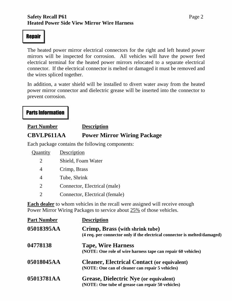
The heated power mirror electrical connectors for the right and left heated power
mirrors will be inspected for corrosion. All vehicles will have the power feed
electrical terminal for the heated power mirrors relocated to a separate electrical
connector. If the electrical connector is melted or damaged it must be removed and
the wires spliced together.
In addition, a water shield will be installed to divert water away from the heated
power mirror connector and dielectric grease will be inserted into the connector to
prevent corrosion.
Part Number Description
CBVLP611AA Power Mirror Wiring Package
Each package contains the following components:
Quantity Description
2 Shield, Foam Water
4 Crimp, Brass
4 Tube, Shrink
2 Connector, Electrical (male)
2 Connector, Electrical (female)
Each dealer to whom vehicles in the recall were assigned will receive enough
Power Mirror Wiring Packages to service about 25% of those vehicles.
Part Number Description
05018395AA Crimp, Brass (with shrink tube) (4 req. per connector only if the electrical connector is melted/damaged)
04778138 Tape, Wire Harness (NOTE: One role of wire harness tape can repair 60 vehicles)
05018045AA Cleaner, Electrical Contact (or equivalent) (NOTE: One can of cleaner can repair 5 vehicles)
05013781AA Grease, Dielectric Nye (or equivalent) (NOTE: One tube of grease can repair 50 vehicles)
Repair
Parts Information
Safety Recall P61 Page 3
Heated Power Side View Mirror Wire Harness
The following special tools are required to perform this repair:
10042* Wire splice crimp tool
* NOTE: One wire splice crimp tool was mailed to each Chrysler/Jeep/Dodge
dealer free of charge in June, 2007.
Additional wire splice crimp tools can be purchased, at dealer expense, by
calling Mopar Essential Tools at 1-855-298-2687 during regular business
hours. Contact Mopar Essential Tools regarding warranty issues on any
purchased tools.
No parts return required for this campaign.
Special Tools
Parts Return
Safety Recall P61 Page 4
Heated Power Side View Mirror Wire Harness
1. Place both front windows in the full up position.
2. Open the hood.
3. Disconnect and isolate the negative battery cable.
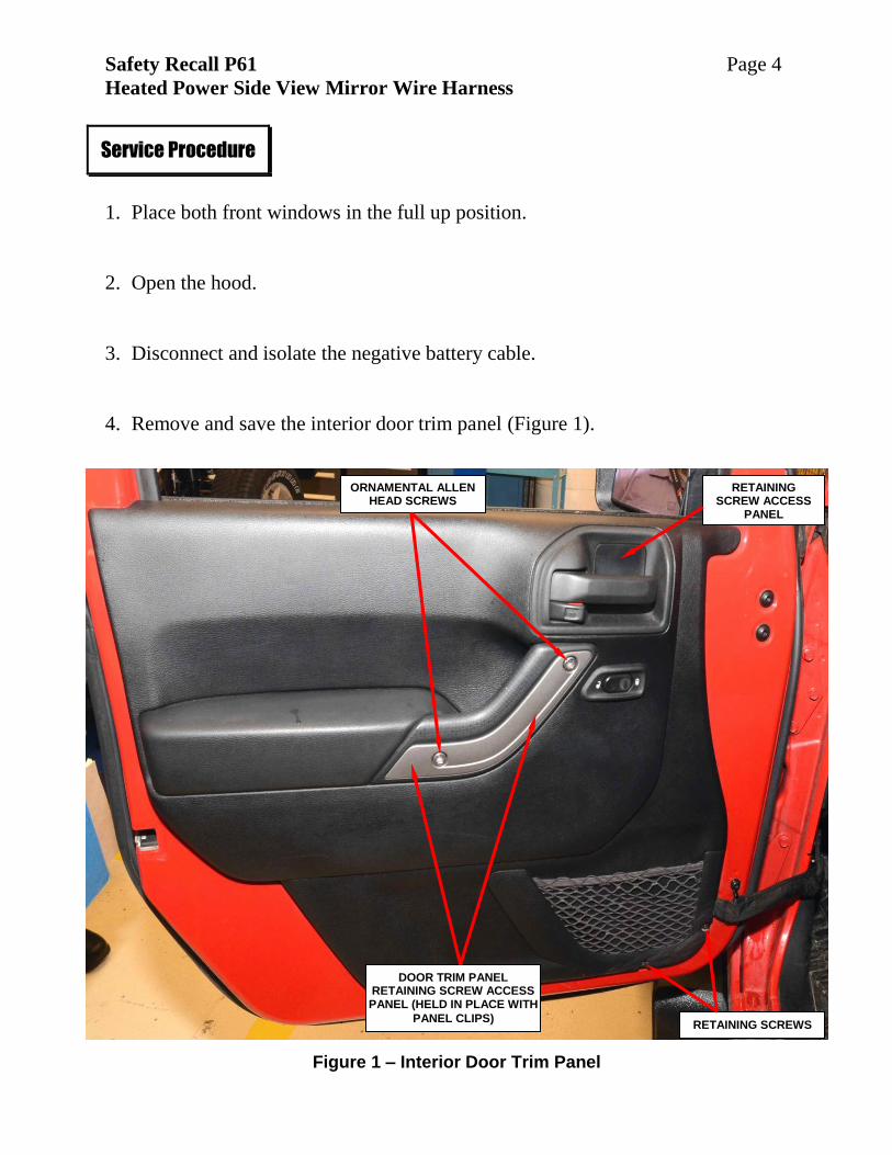
4. Remove and save the interior door trim panel (Figure 1).
Service Procedure
Figure 1 – Interior Door Trim Panel
RETAINING SCREWS
RETAINING SCREW ACCESS
PANEL
ORNAMENTAL ALLEN HEAD SCREWS
DOOR TRIM PANEL RETAINING SCREW ACCESS PANEL (HELD IN PLACE WITH
PANEL CLIPS)
Safety Recall P61 Page 5
Heated Power Side View Mirror Wire Harness
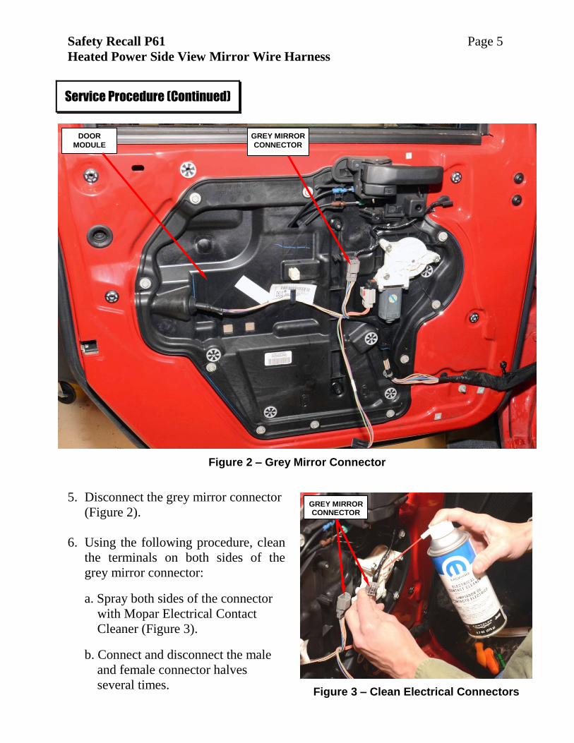
5. Disconnect the grey mirror connector
(Figure 2).
6. Using the following procedure, clean
the terminals on both sides of the
grey mirror connector:
a. Spray both sides of the connector
with Mopar Electrical Contact
Cleaner (Figure 3).
b. Connect and disconnect the male
and female connector halves
several times.
Service Procedure (Continued)
Figure 2 – Grey Mirror Connector
Figure 3 – Clean Electrical Connectors
DOOR
MODULE
GREY MIRROR
CONNECTOR
GREY MIRROR CONNECTOR
Safety Recall P61 Page 6
Heated Power Side View Mirror Wire Harness
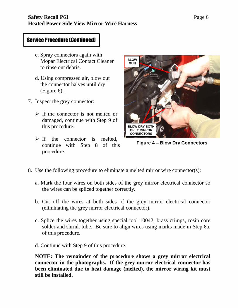
c. Spray connectors again with
Mopar Electrical Contact Cleaner
to rinse out debris.
d. Using compressed air, blow out
the connector halves until dry
(Figure 6).
7. Inspect the grey connector:
If the connector is not melted or
damaged, continue with Step 9 of
this procedure.
If the connector is melted,
continue with Step 8 of this
procedure.
8. Use the following procedure to eliminate a melted mirror wire connector(s):
a. Mark the four wires on both sides of the grey mirror electrical connector so
the wires can be spliced together correctly.
b. Cut off the wires at both sides of the grey mirror electrical connector
(eliminating the grey mirror electrical connector).
c. Splice the wires together using special tool 10042, brass crimps, rosin core
solder and shrink tube. Be sure to align wires using marks made in Step 8a.
of this procedure.
d. Continue with Step 9 of this procedure.
NOTE: The remainder of the procedure shows a grey mirror electrical
connector in the photographs. If the grey mirror electrical connector has
been eliminated due to heat damage (melted), the mirror wiring kit must
still be installed.
Service Procedure (Continued)
Figure 4 – Blow Dry Connectors
BLOW GUN
BLOW DRY BOTH GREY MIRROR CONNECTORS
Safety Recall P61 Page 7
Heated Power Side View Mirror Wire Harness
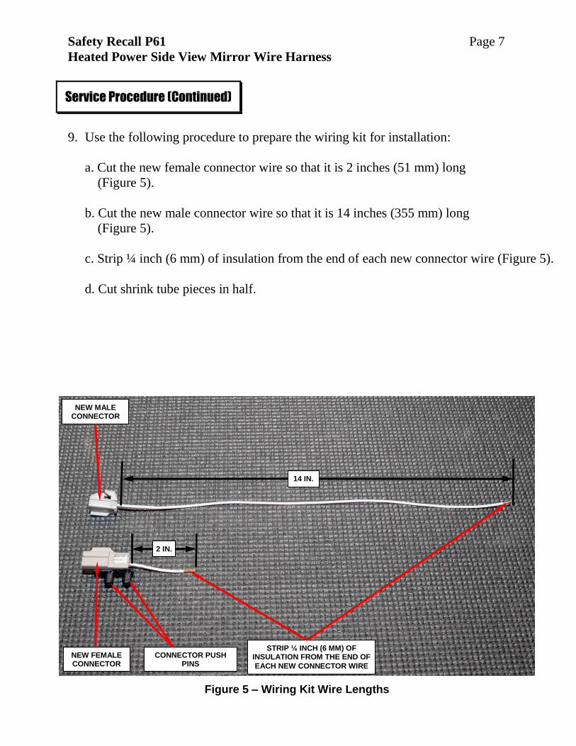
9. Use the following procedure to prepare the wiring kit for installation:
a. Cut the new female connector wire so that it is 2 inches (51 mm) long
(Figure 5).
b. Cut the new male connector wire so that it is 14 inches (355 mm) long
(Figure 5).
c. Strip ¼ inch (6 mm) of insulation from the end of each new connector wire (Figure 5).
d. Cut shrink tube pieces in half.
Service Procedure (Continued)
Figure 5 – Wiring Kit Wire Lengths
14 IN.
2 IN.
NEW FEMALE CONNECTOR
NEW MALE CONNECTOR
STRIP ¼ INCH (6 MM) OF INSULATION FROM THE END OF
EACH NEW CONNECTOR WIRE
CONNECTOR PUSH PINS
Safety Recall P61 Page 8
Heated Power Side View Mirror Wire Harness
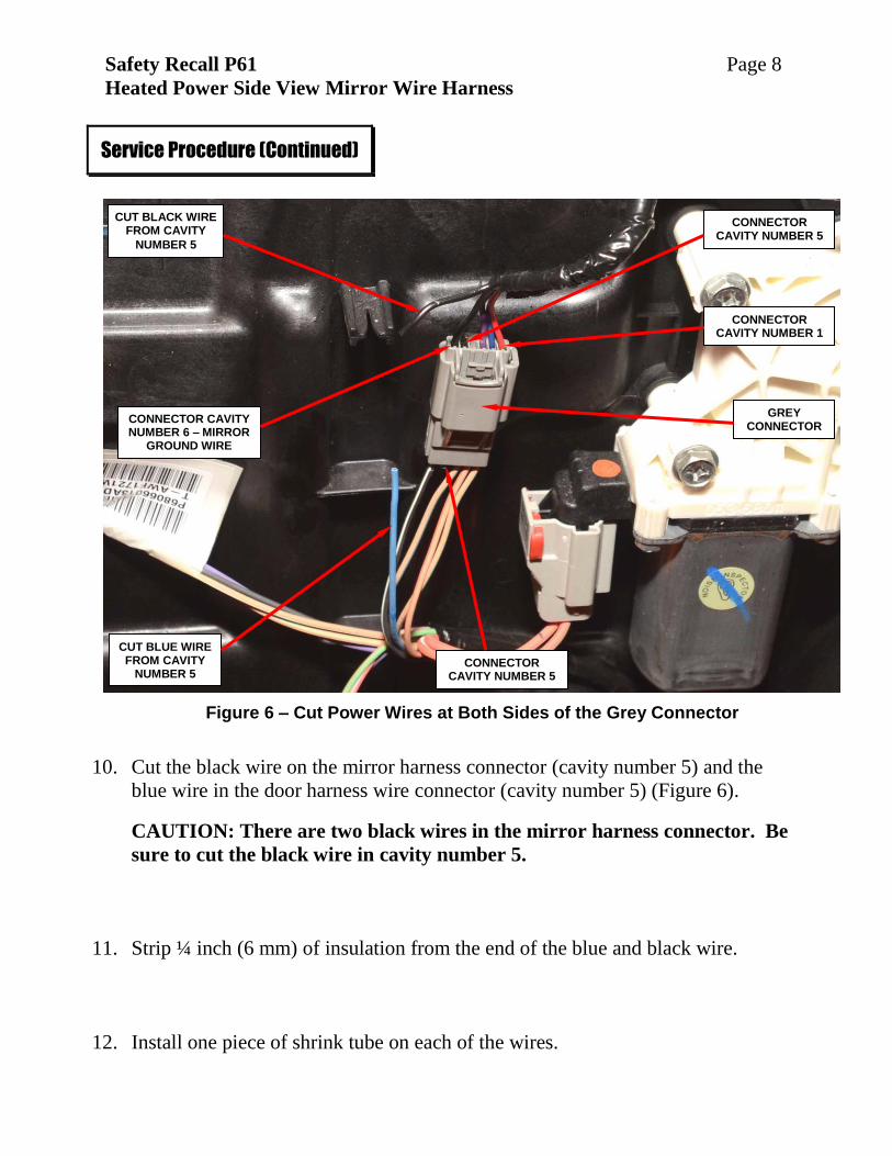
10. Cut the black wire on the mirror harness connector (cavity number 5) and the
blue wire in the door harness wire connector (cavity number 5) (Figure 6).
CAUTION: There are two black wires in the mirror harness connector. Be
sure to cut the black wire in cavity number 5.
11. Strip ¼ inch (6 mm) of insulation from the end of the blue and black wire.
12. Install one piece of shrink tube on each of the wires.
Service Procedure (Continued)
Figure 6 – Cut Power Wires at Both Sides of the Grey Connector
GREY CONNECTOR
CONNECTOR CAVITY NUMBER 5
CONNECTOR CAVITY NUMBER 1
CONNECTOR CAVITY NUMBER 6 – MIRROR
GROUND WIRE
CUT BLACK WIRE FROM CAVITY
NUMBER 5
CUT BLUE WIRE FROM CAVITY
NUMBER 5
CONNECTOR CAVITY NUMBER 5
Safety Recall P61 Page 9
Heated Power Side View Mirror Wire Harness
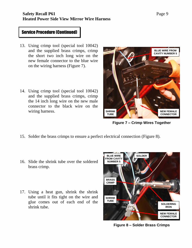
13. Using crimp tool (special tool 10042)
and the supplied brass crimps, crimp
the short two inch long wire on the
new female connector to the blue wire
on the wiring harness (Figure 7).
14. Using crimp tool (special tool 10042)
and the supplied brass crimps, crimp
the 14 inch long wire on the new male
connector to the black wire on the
wiring harness.
15. Solder the brass crimps to ensure a perfect electrical connection (Figure 8).
16. Slide the shrink tube over the soldered
brass crimp.
17. Using a heat gun, shrink the shrink
tube until it fits tight on the wire and
glue comes out of each end of the
shrink tube.
Service Procedure (Continued)
Figure 7 – Crimp Wires Together
Figure 8 – Solder Brass Crimps
BLUE WIRE FROM
CAVITY NUMBER 5
NEW FEMALE CONNECTOR
SHRINK TUBE
NEW FEMALE CONNECTOR
BRASS CRIMP
SOLDERING IRON
BLUE WIRE FROM CAVITY
NUMBER 5
SHRINK TUBE
SOLDER
Safety Recall P61 Page 10
Heated Power Side View Mirror Wire Harness
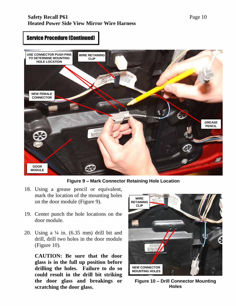
18. Using a grease pencil or equivalent,
mark the location of the mounting holes
on the door module (Figure 9).
19. Center punch the hole locations on the
door module.
20. Using a ¼ in. (6.35 mm) drill bit and
drill, drill two holes in the door module
(Figure 10).
CAUTION: Be sure that the door
glass is in the full up position before
drilling the holes. Failure to do so
could result in the drill bit striking
the door glass and breakings or
scratching the door glass.
Service Procedure (Continued)
Figure 9 – Mark Connector Retaining Hole Location
Figure 10 – Drill Connector Mounting Holes
GREASE PENCIL
USE CONNECTOR PUSH PINS TO DETERMINE MOUNTING
HOLE LOCATION
NEW FEMALE
CONNECTOR
WIRE RETAINING CLIP
WIRE RETAINING
CLIP
NEW CONNECTOR
MOUNTING HOLES
DOOR MODULE
Safety Recall P61 Page 11
Heated Power Side View Mirror Wire Harness
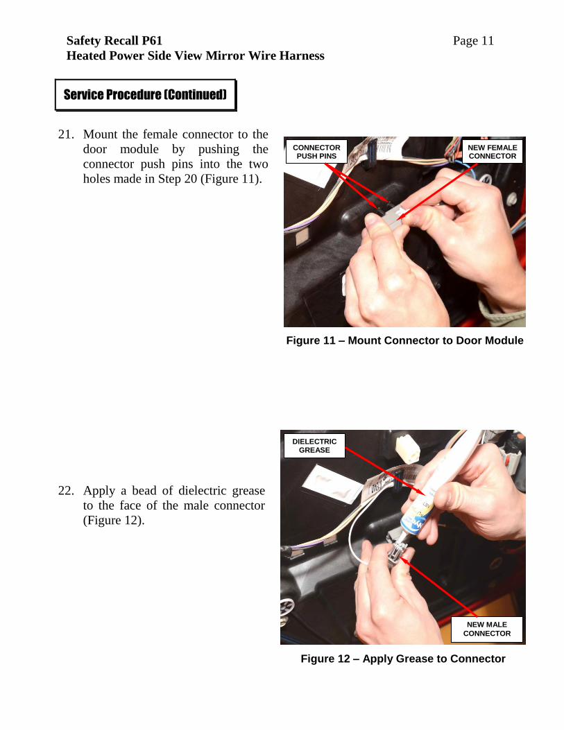
21. Mount the female connector to the
door module by pushing the
connector push pins into the two
holes made in Step 20 (Figure 11).
22. Apply a bead of dielectric grease
to the face of the male connector
(Figure 12).
Service Procedure (Continued)
Figure 11 – Mount Connector to Door Module
Figure 12 – Apply Grease to Connector
CONNECTOR PUSH PINS
NEW FEMALE CONNECTOR
NEW MALE
CONNECTOR
DIELECTRIC GREASE
Safety Recall P61 Page 12
Heated Power Side View Mirror Wire Harness
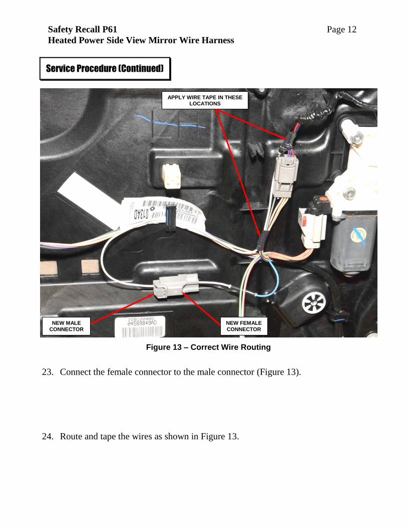
23. Connect the female connector to the male connector (Figure 13).
24. Route and tape the wires as shown in Figure 13.
Service Procedure (Continued)
Figure 13 – Correct Wire Routing
APPLY WIRE TAPE IN THESE LOCATIONS
NEW FEMALE
CONNECTOR NEW MALE
CONNECTOR
Safety Recall P61 Page 13
Heated Power Side View Mirror Wire Harness
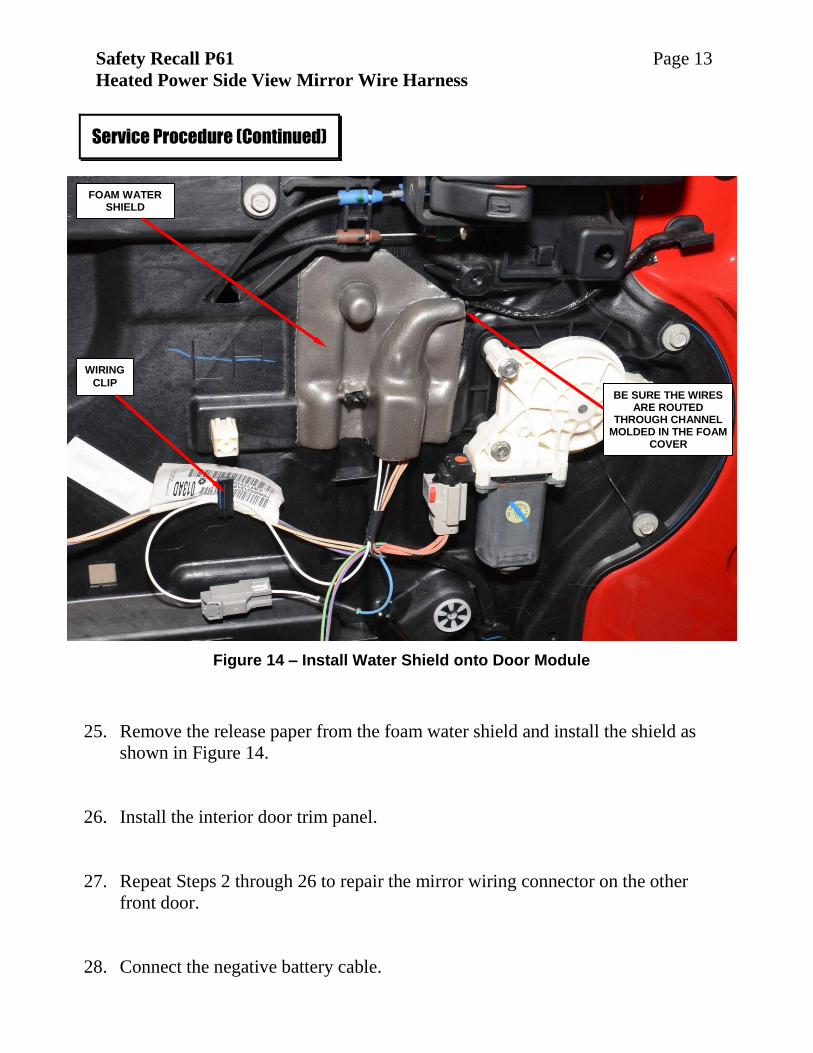
25. Remove the release paper from the foam water shield and install the shield as
shown in Figure 14.
26. Install the interior door trim panel.
27. Repeat Steps 2 through 26 to repair the mirror wiring connector on the other
front door.
28. Connect the negative battery cable.
Service Procedure (Continued)
Figure 14 – Install Water Shield onto Door Module
FOAM WATER SHIELD
BE SURE THE WIRES ARE ROUTED
THROUGH CHANNEL MOLDED IN THE FOAM
COVER
WIRING
CLIP
Safety Recall P61 Page 14
Heated Power Side View Mirror Wire Harness
29. For vehicles that had Service Bulletin 08-100-14 performed:
a. Open the hood.
b. Open the Totally Integrated Power Module (TIPM) cover.
c. Install the 10 amp red (M35) heated mirrors fuse into the TIPM.
NOTE: Refer to the fuse location printed on the back side of the TIPM
cover.
d. Close the TIPM cover.
e. Close the hood.
30. Verify all of the following door functions:
Mirror adjustment function (up, down, right, left)
Power lock function (lock/unlock)
Power window function (up/down)
Power mirror heat function (turn on rear defroster)
31. Using an appropriate cleaner, clean the front door panels and glass.
32. Return the vehicle to the customer.
Service Procedure (Continued)
Safety Recall P61 Page 15
Heated Power Side View Mirror Wire Harness
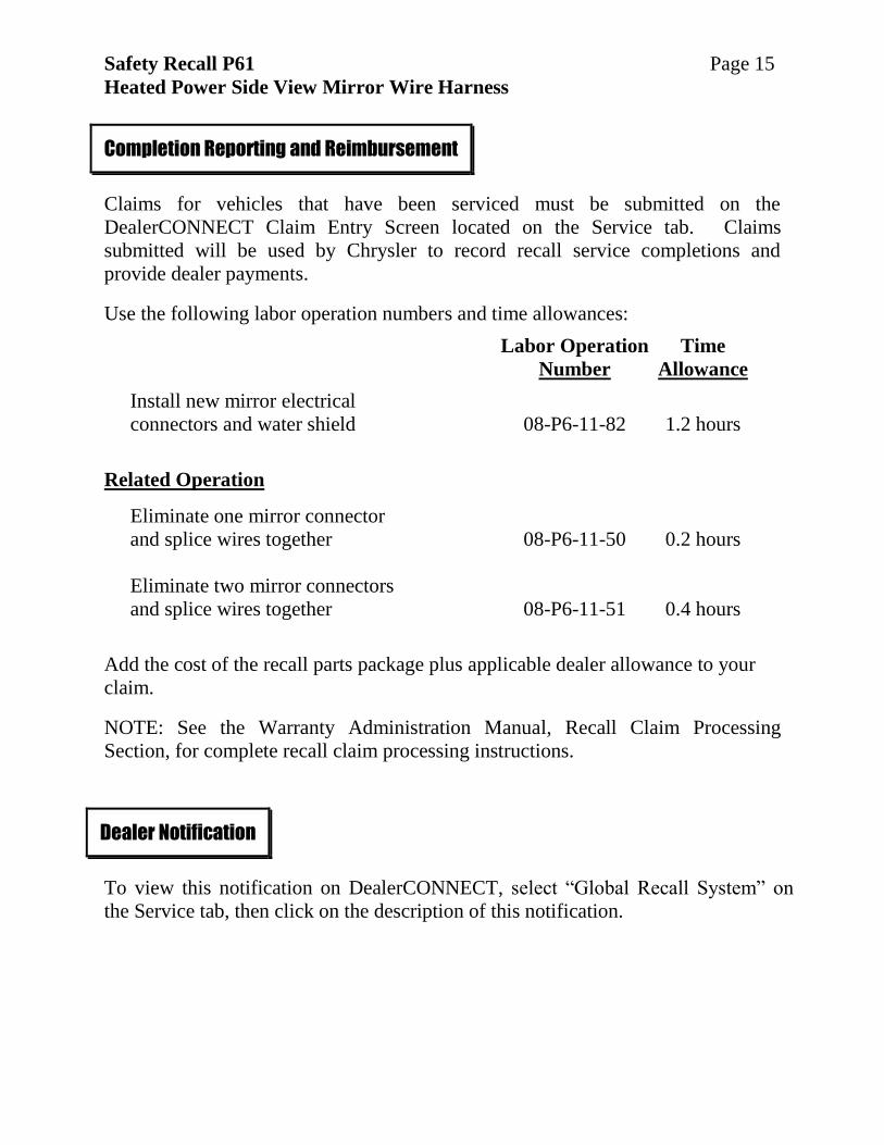
Claims for vehicles that have been serviced must be submitted on the
DealerCONNECT Claim Entry Screen located on the Service tab. Claims
submitted will be used by Chrysler to record recall service completions and
provide dealer payments.
Use the following labor operation numbers and time allowances:
Labor Operation Time
Number Allowance
Install new mirror electrical
connectors and water shield 08-P6-11-82 1.2 hours
Related Operation
Eliminate one mirror connector
and splice wires together 08-P6-11-50 0.2 hours
Eliminate two mirror connectors
and splice wires together 08-P6-11-51 0.4 hours
Add the cost of the recall parts package plus applicable dealer allowance to your
claim.
NOTE: See the Warranty Administration Manual, Recall Claim Processing
Section, for complete recall claim processing instructions.
To view this notification on DealerCONNECT, select “Global Recall System” on
the Service tab, then click on the description of this notification.
Completion Reporting and Reimbursement
Dealer Notification
Safety Recall P61 Page 16
Heated Power Side View Mirror Wire Harness
All involved vehicle owners known to Chrysler are being notified of the service
requirement by first class mail. They are requested to schedule appointments for
this service with their dealers. A generic copy of the owner letter is attached.
Enclosed with each owner letter is an Owner Notification postcard to allow owners
to update our records if applicable.
Dealers are encouraged to consider alternative scheduling and servicing
approaches for this recall. This repair does not require hoists or other full service
facility special equipment and is a Chrysler Mobile Service approved repair.
All involved vehicles have been entered into the DealerCONNECT Global Recall
System (GRS) and Vehicle Information Plus (VIP) for dealer inquiry as needed.
GRS provides involved dealers with an updated VIN list of their incomplete vehicles.
The owner’s name, address and phone number are listed if known. Completed
vehicles are removed from GRS within several days of repair claim submission.
To use this system, click on the “Service” tab and then click on “Global Recall
System.” Your dealer’s VIN list for each recall displayed can be sorted by: those
vehicles that were unsold at recall launch, those with a phone number, city, zip code,
or VIN sequence.
Dealers must perform this repair on all unsold vehicles before retail delivery.
Dealers should also use the VIN list to follow up with all owners to schedule
appointments for this repair.
Recall VIN lists may contain confidential, restricted owner name and address information that was
obtained from the Department of Motor Vehicles of various states. Use of this information is
permitted for this recall only and is strictly prohibited from all other use.
If you have any questions or need assistance in completing this action, please contact
your Service and Parts District Manager.
Customer Services / Field Operations
FCA US LLC
Owner Notification and Service Scheduling
Vehicle Lists, Global Recall System, VIP and Dealer Follow Up
Additional Information