Embed Size (px)
Citation preview

The repair information in this document is intended for use only by skilled technicians who have the proper tools, equipment and training to correctly and safely maintain your vehicle. These procedures are not intended to be attempted by “do-it-yourselfers,” and you should not assume this document applies to your vehicle, or that your vehicle has the condition described. To determine whether this information applies, contact an authorized Volkswagen dealer. 2017 Volkswagen Group of America, Inc. and Volkswagen Canada. All Rights Reserved.
March 2017 45F2 Page 1 of 59
Safety Recall Code: 45F2
REVISION
Subject ABS Control Module Software
Release Date March 17, 2017
Revision Summary Work procedure and claiming instructions updated.
Affected Vehicles Certain 2009-2010 MY Volkswagen Vehicles
Check Campaigns/Actions screen in Elsa on the day of repair to verify that a VIN qualifies for repair under this action. Elsa is the only valid campaign inquiry & verification source.
Campaign status must show “open.”
If Elsa shows other open action(s), inform your customer so that the work can also be completed at the same time the vehicle is in the workshop for this campaign.
Problem Description On certain vehicles, a fault within the antilock brake system (ABS) may cause the module to fail during ABS and/or electronic stability control (ESC) activation. This will cause warning lights for ABS, brake and the ESC systems to illuminate. If this happens, the brake system related vehicle stabilizing functions (ABS/ESC) may not be available, increasing the risk of a loss of vehicle control and could lead to a crash causing injury and/or property damage.
Corrective Action Update the ABS control module software with improved diagnostic capability to detect insufficient PCU ground connection. ABS modules with insufficient ground connections will be replaced.
Precautions If the ABS/ESC and/or brake system warning lights illuminate at any time while driving, or if any of the lights have been illuminated and then turn off after an ignition key cycle, the customer should contact the nearest authorized Volkswagen dealer to have their vehicle inspected. Ensure all vehicle drivers have read the vehicle owner’s manual so they are familiar with how the ABS, ESC and vehicle brake systems and associated warning lights work.
Parts Information Software update – however, please note: due to the very low expected parts replacement rate, there will be no parts allocation. If parts are needed to support a vehicle repair, submit your request with VIN via email to [email protected].
Code Visibility On or about February 14, 2017, affected vehicles will be listed on the Inventory Vehicle Open Campaign Action report under My Dealership Reports (found on www.vwhub.com & OMD Web). A list will not be posted for dealers who do not have any affected vehicles.
On or about February 14, 2017, this campaign code will show open on affected vehicles in Elsa.
On or about February 14, 2017, affected vehicles will be identified with this campaign code in the VIN Lookup tool at www.vw.com and on the NHTSA VIN lookup tool at www.safercar.gov.
Owner Notification Owner notification will take place on or about February 14, 2017. Owner letter examples are included in this bulletin for your reference.
Additional Information Please alert everyone in your dealership about this action, including Sales, Service, Parts and Accounting personnel. Contact Warranty if you have any questions.
IMPORTANT REMINDER ON VEHICLES AFFECTED BY SAFETY & COMPLIANCE RECALLS
New Vehicles in Dealer Inventory: It is a violation of Federal law for a dealer to deliver a new motor vehicle or any new or used item of motor vehicle equipment (including a tire) covered by this notification under a sale or lease until the defect or noncompliance is remedied. By law, dealers must correct, prior to delivery for sale or lease, any vehicle that fails to comply
The information in this document is intended for use only by skilled technicians who have the proper tools, equipment and training to correctly and safely maintain your vehicle. These procedures are not intended to be attempted by “do-it-yourselfers,” and you should not assume this document applies to your vehicle, or that your vehicle has the condition described. To determine whether this information applies, contact an authorized Volkswagen dealer. 2017 Volkswagen Group of America, Inc. and Volkswagen Canada. All Rights Reserved.
March 2017 45F2 Page 2 of 59
with an applicable Federal Motor Vehicle Safety Standard or that contains a defect relating to motor vehicle safety.
Pre-Owned Vehicles in Dealer Inventory: Dealers should not deliver any pre-owned vehicles in their inventory which are involved in a safety or compliance recall until the defect has been remedied.
Dealers must ensure that every affected inventory vehicle has this campaign completed before delivery to consumers.
Fill out and affix Campaign Completion Label (CAMP 010 000) after work is complete. Labels can be ordered at no cost via the Compliance Label Ordering portal at www.vwhub.com.

The repair information in this document is intended for use only by skilled technicians who have the proper tools, equipment and training to correctly and safely maintain your vehicle. These procedures are not intended to be attempted by “do-it-yourselfers,” and you should not assume this document applies to your vehicle, or that your vehicle has the condition described. To determine whether this information applies, contact an authorized Volkswagen dealer. 2017 Volkswagen Group of America, Inc. and Volkswagen Canada. All Rights Reserved.
March 2017 45F2 Page 3 of 59
Claim Entry Instructions
After campaign has been completed, enter claim as soon as possible to help prevent work from being duplicated elsewhere. Attach the Elsa screen print showing action open on the day of repair to the repair order.
If customer refused campaign work:
U.S. dealers: Submit request via WISE under the Campaigns/Update/Recall Closure option.
Canada dealers: Fax repair order to Warranty at (905) 428-4811.
Service Number 45F2
Damage Code 0099
Parts Vendor Code WWO
Claim Type Sold vehicle: 7 10
Unsold vehicle: 7 90
Causal Indicator Mark labor as causal
Vehicle Wash/Loaner Do not claim wash/loaner under this action
Criteria I.D. 01
Connect battery charger
Repair operation: 2706 89 50 10 T.U.
--AND--
Update ABS Control Module Software
Repair operation: 4545 25 99 Time stated on diagnostic protocol (max 50 TU)
AND - (ONLY if necessary from diagnostic log)
Replace ABS Control Module (Gasoline engines ONLY)
Labor operation: 4545 23 99 430 T.U.
Quantity Part Number Description 1.00 1K0907375AP ABS Control Module -OR- 1.00 1K0907375AN ABS Control Module
-AND-
Up to 8.00 B 000750M2 Brake Fluid -OR-
Replace ABS Control Module (Diesel engines ONLY) Labor operation: 4545 24 99 490 T.U.
Quantity Part Number Description 1.00 1K0907375AP ABS Control Module -OR- 1.00 1K0907375AN ABS Control Module
-AND- Continue to next page
The repair information in this document is intended for use only by skilled technicians who have the proper tools, equipment and training to correctly and safely maintain your vehicle. These procedures are not intended to be attempted by “do-it-yourselfers,” and you should not assume this document applies to your vehicle, or that your vehicle has the condition described. To determine whether this information applies, contact an authorized Volkswagen dealer. 2017 Volkswagen Group of America, Inc. and Volkswagen Canada. All Rights Reserved.
March 2017 45F2 Page 4 of 59
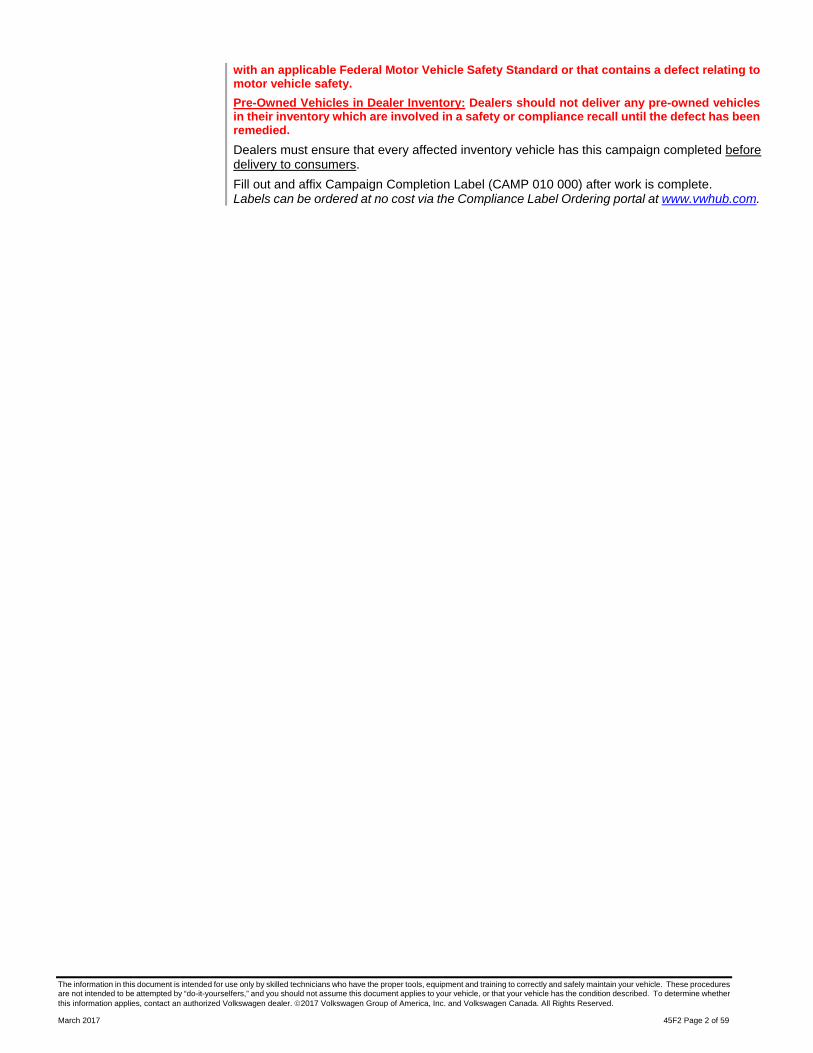
Quantity Part Number Description 1.00 1K0253725 Turbo to Particulate Filter Clamp 1.00 1K0253115T Gasket 1.00 1K0253725E EGR Filter to Particulate Filter Clamp 1.00 1K0253115AG Gasket Up to 8.00 B 000750M3 Brake Fluid 6.00 N 90991102 Drive Axle Bolt - Manual gearbox = M10x52 mm-OR- 6.00 N 90991002 Drive Axle Bolt - Dual clutch gearbox (DSG)
= M10x23 mm

The repair information in this document is intended for use only by skilled technicians who have the proper tools, equipment and training to correctly and safely maintain your vehicle. These procedures are not intended to be attempted by “do-it-yourselfers,” and you should not assume this document applies to your vehicle, or that your vehicle has the condition described. To determine whether this information applies, contact an authorized Volkswagen dealer. 2017 Volkswagen Group of America, Inc. and Volkswagen Canada. All Rights Reserved.
March 2017 45F2 Page 5 of 59
Customer Letter Example (USA)
NHTSA: 16V913
Subject: Safety Recall 45F2 - ABS Control Module Software Certain 2009-2010 Model Year Volkswagen Vehicles
Dear Volkswagen Owner,
This notice is sent to you in accordance with the National Traffic and Motor Vehicle Safety Act. Volkswagen has decided that a defect, which relates to motor vehicle safety, exists in certain 2009-2010 model year Volkswagen vehicles. Our records show that you are the owner of a vehicle affected by this action.
What is the issue? On certain vehicles, a fault within the antilock brake system (ABS) may cause the module to fail during ABS and/or electronic stability control (ESC) activation. This will cause warning lights for ABS, brake and the ESC systems to illuminate. If this happens, the brake system related vehicle stabilizing functions (ABS/ESC) may not be available, increasing the risk of a loss of vehicle control and could lead to a crash causing injury and/or property damage.
What will we do? To help correct this defect, your authorized Volkswagen dealer will update the ABS control module software with improved diagnostic capability to detect insufficient PCU ground connection. ABS modules with insufficient ground connections will be replaced. The software update will take less than an hour to complete; if the ABS module requires replacement, this work can take up to a full day to complete. The recall repair will be performed for you free of charge.
Should there ever be an issue with the ABS control module after the new software is installed, an authorized Volkswagen dealer will cover replacement of the ABS control module if certain, specific fault codes are present at the time of diagnosis.
Please be aware that other conditions (unrelated to the issue described in this letter) may cause the ABS system warning light in your vehicle to illuminate. Customers should be prepared to cover diagnosis and repair costs associated with these other, unrelated conditions.
What should you do? Please contact your authorized Volkswagen dealer without delay to schedule this recall repair. For your convenience, you can also visit www.vw.com and click on the “Owners” link to locate a dealer near you and schedule this service online.
Precautions you should take
If the ABS/ESC and/or brake system warning lights illuminate at any time while driving, or if any of the lights have been illuminated and then turn off after an ignition key cycle, contact the nearest authorized Volkswagen dealer to have your vehicle inspected.
Ensure all vehicle drivers have read the vehicle owner’s manual so they are familiar with how the ABS, ESC and vehicle brake systems and associated warning lights work.
Lease vehicles and address changes
If you are the lessor and registered owner of the vehicle identified in this action, the law requires you to forward this letter immediately via first-class mail to the lessee within ten (10) days of receipt. If you have changed your address or sold the vehicle, please fill out the enclosed prepaid Owner Reply card and mail it to us so we can update our records.
Reimbursement of Expenses
If you have previously paid for repairs relating to the condition described in this letter, please refer to the enclosed form that explains how to request reimbursement.
Can we assist you further?
If your authorized Volkswagen dealer fails or is unable to complete this work free of charge within a reasonable time, or if you should have any questions about this communication, please reach out to us using your preferred method of communication at www.vw.com/contact or by calling 1 800-893-5298. Our phone team is available Monday through Friday from 8AM to 10PM EST and Saturday from 9AM to 5PM EST.
Checking your vehicle for open Recalls and Service Campaigns
To check your vehicle’s eligibility for repair under this or any other recall/service campaign, please click on the Look Up Recalls link at www.vw.com and enter your Vehicle Identification Number (VIN) into the Recall/Service Campaign Lookup tool.
If you still cannot obtain satisfaction, you may file a complaint with: The Administrator, National Highway Traffic Safety Administration, 1200 New Jersey Avenue, SE., Washington, DC 20590; or call the toll-free Vehicle Safety Hotline at 1-888-327-4236 (TTY: 1-800-424-9153); or go to http://www.safercar.gov.
We apologize for any inconvenience this matter may cause; however we are taking this action to help ensure your safety and continued satisfaction with your vehicle.
Sincerely,
Volkswagen Customer Protection

The repair information in this document is intended for use only by skilled technicians who have the proper tools, equipment and training to correctly and safely maintain your vehicle. These procedures are not intended to be attempted by “do-it-yourselfers,” and you should not assume this document applies to your vehicle, or that your vehicle has the condition described. To determine whether this information applies, contact an authorized Volkswagen dealer. 2017 Volkswagen Group of America, Inc. and Volkswagen Canada. All Rights Reserved.
March 2017 45F2 Page 6 of 59
Customer Letter Example (CANADA)
Subject: Safety Recall 45F2 - ABS Control Module Software Certain 2009-2010 Model Year Volkswagen Vehicles Dear Volkswagen Owner,
This notice is sent to you in accordance with the requirements of the Motor Vehicle Safety Act. Volkswagen has decided that a defect, which relates to motor vehicle safety, exists in certain 2009-2010 model year Volkswagen vehicles. Our records show that you are the owner of a vehicle affected by this action.
What is the issue? On certain vehicles, a fault within the antilock brake system (ABS) may cause the module to fail during ABS and/or electronic stability control (ESC) activation. This will cause warning lights for ABS, brake and the ESC systems to illuminate. If this happens, the brake system related vehicle stabilizing functions (ABS/ESC) may not be available, increasing the risk of a loss of vehicle control and could lead to a crash causing injury and/or property damage.
What will we do? To help correct this defect, your authorized Volkswagen dealer will update To help correct this defect, your authorized Volkswagen dealer will update the ABS control module software with improved diagnostic capability to detect insufficient PCU ground connection. ABS modules with insufficient ground connections will be replaced. The software update will take less than an hour to complete; if the ABS module requires replacement, this work can take up to a full day to complete. The recall repair will be performed for you free of charge.
Should there ever be an issue with the ABS control module after the new software is installed, an authorized Volkswagen dealer will cover replacement of the ABS control module if certain, specific fault codes are present at the time of diagnosis.
Please be aware that other conditions (unrelated to the issue described in this letter) may cause the ABS system warning light in your vehicle to illuminate. Customers should be prepared to cover diagnosis and repair costs associated with these other, unrelated conditions.
What should you do? Please contact your authorized Volkswagen dealer without delay to schedule this recall repair.
Precautions you should take
If the ABS/ESC and/or brake system warning lights illuminate at any time while driving, or if any of the lights have been illuminated and then turn off after an ignition key cycle, contact the nearest authorized Volkswagen dealer to have your vehicle inspected. Ensure all vehicle drivers have read the vehicle owner’s manual so they are familiar with how the ABS, ESC and vehicle brake systems and associated warning lights work.
Lease vehicles and address changes
If you are the lessor and registered owner of the vehicle identified in this action, the law requires you to forward this letter immediately via first-class mail to the lessee within ten (10) days of receipt. If you have changed your address or sold the vehicle, please fill out the enclosed prepaid Owner Reply card and mail it to us so we can update our records.
Reimbursement of Expenses
If you have previously paid for repairs relating to the condition described in this letter, please refer to the enclosed form that explains how to request reimbursement.
Can we assist you further?
If your authorized Volkswagen dealer fails or is unable to complete this work free of charge within a reasonable time, please contact Customer Relations, Monday through Friday from 8AM to 8PM EST by phone at 1-800-822-8987 or via our “Contact Us” page at www.vw.ca.
We apologize for any inconvenience this matter may cause; however we are taking this action to help ensure your safety and continued satisfaction with your vehicle.
Sincerely,
Volkswagen Customer Protection

The repair information in this document is intended for use only by skilled technicians who have the proper tools, equipment and training to correctly and safely maintain your vehicle. These procedures are not intended to be attempted by “do-it-yourselfers,” and you should not assume this document applies to your vehicle, or that your vehicle has the condition described. To determine whether this information applies, contact an authorized Volkswagen dealer. 2017 Volkswagen Group of America, Inc. and Volkswagen Canada. All Rights Reserved.
March 2017 45F2 Page 7 of 59
Campaign Work Procedure 45F2 Safety Recall
WARNING
Risk of injury. Refer to “Warning and Safety Precautions”, found in Appendix A at the end of this document.
CAUTION
Refer to “Antilock Brake System (ABS) Repair Information”, found in Appendix B at the end of this document.
NOTE
Damages resulting from improper repair or failure to follow these work instructions are the dealer’s responsibility and are not eligible for reimbursement under this action.
This procedure must be read in its entirety prior to performing the repair.
Due to variations in vehicle equipment and options, the steps/illustrations in this work procedure may not identically match all affected vehicles.
Diagnosis and repair of any faults stored in the ABS Control Module other than the faults listed in the circular will not be covered under this Campaign.
The repair information in this document is intended for use only by skilled technicians who have the proper tools, equipment and training to correctly and safely maintain your vehicle. These procedures are not intended to be attempted by “do-it-yourselfers,” and you should not assume this document applies to your vehicle, or that your vehicle has the condition described. To determine whether this information applies, contact an authorized Volkswagen dealer. 2017 Volkswagen Group of America, Inc. and Volkswagen Canada. All Rights Reserved.
March 2017 45F2 Page 8 of 59
Repair Instruction
Section A - Check for Previous Repair
TIP
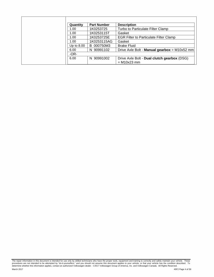
If Campaign Completion label is present, no further work is required.
Enter the VIN in Elsa and proceed to the
“Campaign/Action” screen.
TIP
On the date of repair, print this screen and keep a copy with the repair order.
Confirm the Campaign/Action is open <arrow 1>.
If the status is closed, no further work is required.
o Note the Applicable Criteria ID <arrow 2> for use in determining the correct work to be done and corresponding parts associated. Proceed to Section B

The repair information in this document is intended for use only by skilled technicians who have the proper tools, equipment and training to correctly and safely maintain your vehicle. These procedures are not intended to be attempted by “do-it-yourselfers,” and you should not assume this document applies to your vehicle, or that your vehicle has the condition described. To determine whether this information applies, contact an authorized Volkswagen dealer. 2017 Volkswagen Group of America, Inc. and Volkswagen Canada. All Rights Reserved.
March 2017 45F2 Page 9 of 59
Section B – Repair Procedure
NOTE
Prior to launching the VAS Diagnostic Tester and starting an update, ensure the following conditions are met;
The battery charger is connected to the vehicle battery and remains connected for the duration of the software update.
Battery voltage must remain above 12.6 volts for the duration of the software update. Failure to do so may cause the update to fail, which could result in damage to the control module. Control modules damaged by insufficient voltage will not be covered.
The screen saver and power saving settings are off.
Failure to do so may result in the tester entering power save mode during the software update, which could result in damage to the control module.
The VAS Diagnostic Tester is plugged in using the supplied power adapters.
Under no circumstances should the tester be used on battery power alone during the software
update. Failure to do so may result in the tester powering off during the update, which could result in damage to the control module.
If using a Bluetooth transmitter head, it is connected to the tester with a USB cable.
NOTE
Using Bluetooth for this action is PROHIBITED!
Damage caused to electronic components (e.g. ABS Control Module, etc.) during the SVM flash process is not covered.
Performing a software update using a Bluetooth connection increases the risk of losing
connection during the update, which could result in damage to the control module. It also greatly increases the time required to perform the update. Requests for additional time or parts will be denied if the GFF log shows the update was performed using Bluetooth.
The Bluetooth function of the scan tool is physically switched off <see pictures below>.
VAS 6150 & VAS 6150A (Front panel behind handle)
VAS 6150B (Right side behind WIRELESS door)
VAS 6150C/D (Left side behind SC/EX door)

The repair information in this document is intended for use only by skilled technicians who have the proper tools, equipment and training to correctly and safely maintain your vehicle. These procedures are not intended to be attempted by “do-it-yourselfers,” and you should not assume this document applies to your vehicle, or that your vehicle has the condition described. To determine whether this information applies, contact an authorized Volkswagen dealer. 2017 Volkswagen Group of America, Inc. and Volkswagen Canada. All Rights Reserved.
March 2017 45F2 Page 10 of 59
WARNING
Radiator Fan(s) may cycle ON high speed during the Update Process! There is a serious risk that personal injury may result if contact is made with spinning fan blades. Keep hands and all objects away from Radiator Fan(s) during Update Process!
TIP
To Update-Programming using SVM, review and follow instructions in Technical Bulletin 2014603: Software Version Management (SVM) Operating Instructions.
Ensure the ODIS tester is updated to the latest version.
The SVM Process must be completed in its entirety so the database receives the update confirmation response. A warranty claim may not be reimbursed if there is no confirmation response to support the claim.
Open the hood.
Open the battery cover.
Attach the GRX3000VAS Tester/Charger (or equivalent) to the vehicle battery.
Switch the ignition on.
Apply the parking brake.
Turn off all consumers; headlights heated seats, etc.
Connect the VAS6150D Diagnostic Tester (or equivalent) to the vehicle.
Start the ODIS program.
Confirm that scan tool is communicating with the diagnostic head by USB <Green Arrow>.
If the Bluetooth symbol is shown <Red Arrow> then disconnect the diagnostic head from the vehicle and reconnect the USB cable to the diagnostic head and then reattach to the vehicle.
Upon ODIS startup, verify the “Diagnosis” operating mode is selected <as shown>.
Select “Starting Diagnosis” and perform a GFF scan of the vehicle.
NOTE
Using Bluetooth for this action is PROHIBITED!
Damage caused to electronic components (e.g. ABS Control Module, etc.) during the SVM flash process is not covered.

The repair information in this document is intended for use only by skilled technicians who have the proper tools, equipment and training to correctly and safely maintain your vehicle. These procedures are not intended to be attempted by “do-it-yourselfers,” and you should not assume this document applies to your vehicle, or that your vehicle has the condition described. To determine whether this information applies, contact an authorized Volkswagen dealer. 2017 Volkswagen Group of America, Inc. and Volkswagen Canada. All Rights Reserved.
March 2017 45F2 Page 11 of 59
NOTE
Fault 01130 MUST have 125 shown in the 4th line of the Expanded ambient conditions to qualify for ABS module replacement and/or fault 16352 MUST have 96 shown in the 4th line of the Expanded ambient conditions to qualify for ABS module replacement under this Campaign.
Diagnosis and repair of faults other than the faults listed above will not be covered under this Campaign and should be addressed prior to updating the ABS Control Module.
Once the GFF scan is complete: o Record any faults that may be stored. o Select “Special functions” <arrow 1>, then
“Adapting software” <arrow 2>, then select “Perform test” <arrow 3>.
CAUTION
RISK OF NONPAYMENT
The ODIS Diagnostic log MUST now be sent to GFF paperless. Failure to do so could result in non-payment of the warranty claim.
Select the appropriate option to update “through
measures code” <arrow>.
NOTE Read this screen carefully. The option to update software through measures code is NOT always selection #1 on this screen.

The repair information in this document is intended for use only by skilled technicians who have the proper tools, equipment and training to correctly and safely maintain your vehicle. These procedures are not intended to be attempted by “do-it-yourselfers,” and you should not assume this document applies to your vehicle, or that your vehicle has the condition described. To determine whether this information applies, contact an authorized Volkswagen dealer. 2017 Volkswagen Group of America, Inc. and Volkswagen Canada. All Rights Reserved.
March 2017 45F2 Page 12 of 59
Enter “337B” <as shown>.
Select “Accept” <arrow> and follow on screen instructions.
Proceed to Section C.

The repair information in this document is intended for use only by skilled technicians who have the proper tools, equipment and training to correctly and safely maintain your vehicle. These procedures are not intended to be attempted by “do-it-yourselfers,” and you should not assume this document applies to your vehicle, or that your vehicle has the condition described. To determine whether this information applies, contact an authorized Volkswagen dealer. 2017 Volkswagen Group of America, Inc. and Volkswagen Canada. All Rights Reserved.
March 2017 45F2 Page 13 of 59
Section C – ABS Fault Interrogation
NOTE
To activate the self-test of the new software drive the vehicle at a speed of over 10 mi/hr before interrogating faults.
If scan tool is disconnected for the road test, be sure to save the current ODIS session and restart the session when returning from the road test.
After the short road test, turn off the ignition and cycle ignition back on.
Select the “Control Module” tab.
Scroll down and right click on Address Word 0003/ABS Control Module.
Select Check DTC Memory <arrow>.
The repair information in this document is intended for use only by skilled technicians who have the proper tools, equipment and training to correctly and safely maintain your vehicle. These procedures are not intended to be attempted by “do-it-yourselfers,” and you should not assume this document applies to your vehicle, or that your vehicle has the condition described. To determine whether this information applies, contact an authorized Volkswagen dealer. 2017 Volkswagen Group of America, Inc. and Volkswagen Canada. All Rights Reserved.
March 2017 45F2 Page 14 of 59
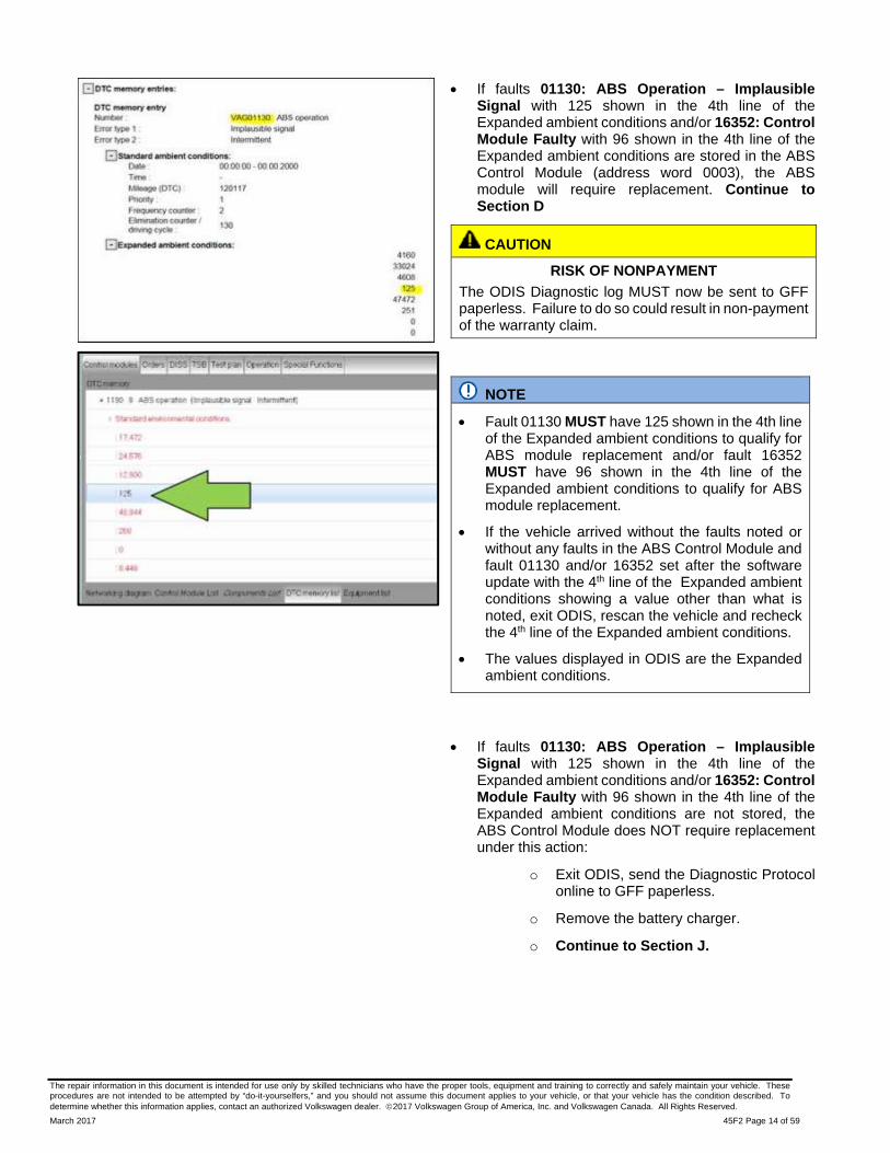
If faults 01130: ABS Operation – Implausible Signal with 125 shown in the 4th line of the Expanded ambient conditions and/or 16352: Control Module Faulty with 96 shown in the 4th line of the Expanded ambient conditions are stored in the ABS Control Module (address word 0003), the ABS module will require replacement. Continue to Section D
CAUTION
RISK OF NONPAYMENT
The ODIS Diagnostic log MUST now be sent to GFF paperless. Failure to do so could result in non-payment of the warranty claim.
NOTE
Fault 01130 MUST have 125 shown in the 4th line of the Expanded ambient conditions to qualify for ABS module replacement and/or fault 16352 MUST have 96 shown in the 4th line of the Expanded ambient conditions to qualify for ABS module replacement.
If the vehicle arrived without the faults noted or without any faults in the ABS Control Module and fault 01130 and/or 16352 set after the software update with the 4th line of the Expanded ambient conditions showing a value other than what is noted, exit ODIS, rescan the vehicle and recheck the 4th line of the Expanded ambient conditions.
The values displayed in ODIS are the Expanded ambient conditions.
If faults 01130: ABS Operation – Implausible Signal with 125 shown in the 4th line of the Expanded ambient conditions and/or 16352: Control Module Faulty with 96 shown in the 4th line of the Expanded ambient conditions are not stored, the ABS Control Module does NOT require replacement under this action:
o Exit ODIS, send the Diagnostic Protocol online to GFF paperless.
o Remove the battery charger.
o Continue to Section J.

The repair information in this document is intended for use only by skilled technicians who have the proper tools, equipment and training to correctly and safely maintain your vehicle. These procedures are not intended to be attempted by “do-it-yourselfers,” and you should not assume this document applies to your vehicle, or that your vehicle has the condition described. To determine whether this information applies, contact an authorized Volkswagen dealer. 2017 Volkswagen Group of America, Inc. and Volkswagen Canada. All Rights Reserved.
March 2017 45F2 Page 15 of 59
Section D – Retrieve ABS Coding and ABS Module Part Number
Right click on Address 0003 (ABS Control Module), select “Control Module OBD” and then select “Identification” <arrow>.
Record the ABS Control Module part # <arrow 1> and the coding of the ABS Control Module <arrow 2> on the repair order. ABS Control Module coding may need to be entered manually after the ABS Control Module is replaced.
Exit ODIS, send the Diagnostic Protocol online to GFF paperless.
CAUTION
ODIS must be exited after the software update and fault interrogation. Starting a saved ODIS session during the ABS Module replacement will result in errors when performing coding and basic settings of the new ABS Module.
Once the new ABS Control Module is on hand for installation, Continue to Section E
NOTE
When ordering a new ABS Control Module, refer to ETKA to ensure the correct part number is ordered. (See parts table below)
Do not continue with this procedure until the new ABS Control Module is ready for installation.

The repair information in this document is intended for use only by skilled technicians who have the proper tools, equipment and training to correctly and safely maintain your vehicle. These procedures are not intended to be attempted by “do-it-yourselfers,” and you should not assume this document applies to your vehicle, or that your vehicle has the condition described. To determine whether this information applies, contact an authorized Volkswagen dealer. 2017 Volkswagen Group of America, Inc. and Volkswagen Canada. All Rights Reserved.
March 2017 45F2 Page 16 of 59
Section E – ABS Module Replacement (all vehicles)
Parts for ABS module replacement (only if necessary)
Quantity Part Number Part Description
1 1K0907375AP ABS Control Module
OR
1 1K0907375AN ABS Control Module
AND
8 B000750M2 Brake Fluid
Additional parts for ABS module replacement on vehicles with diesel engine (only if necessary)
1 1K0253725 Turbo to Particulate Filter Clamp
1 1K0253115T Gasket
1 1K0253725E EGR Filter to Particulate Filter Clamp
1 1K0253115AG Gasket
8 B000750M2 Brake Fluid
6 N.909.911.02 Drive Axle Bolt - Manual gearbox = M10x52 mm
OR
6 N.909.910.02 Drive Axle Bolt - Dual clutch gearbox (DSG) = M10x23 mm

The repair information in this document is intended for use only by skilled technicians who have the proper tools, equipment and training to correctly and safely maintain your vehicle. These procedures are not intended to be attempted by “do-it-yourselfers,” and you should not assume this document applies to your vehicle, or that your vehicle has the condition described. To determine whether this information applies, contact an authorized Volkswagen dealer. 2017 Volkswagen Group of America, Inc. and Volkswagen Canada. All Rights Reserved.
March 2017 45F2 Page 17 of 59
Required Tools
Hose Clip Pliers -VAS6362- (or equivalent)
VAS6150D - Diagnostic Tester (or equivalent)
VAS6154 - Vehicle Communication Interface (or equivalent)

The repair information in this document is intended for use only by skilled technicians who have the proper tools, equipment and training to correctly and safely maintain your vehicle. These procedures are not intended to be attempted by “do-it-yourselfers,” and you should not assume this document applies to your vehicle, or that your vehicle has the condition described. To determine whether this information applies, contact an authorized Volkswagen dealer. 2017 Volkswagen Group of America, Inc. and Volkswagen Canada. All Rights Reserved.
March 2017 45F2 Page 18 of 59
GRX3000VAS – Battery Tester/Charger (or equivalent)
ESD Worksurface - VAS 6613
The repair information in this document is intended for use only by skilled technicians who have the proper tools, equipment and training to correctly and safely maintain your vehicle. These procedures are not intended to be attempted by “do-it-yourselfers,” and you should not assume this document applies to your vehicle, or that your vehicle has the condition described. To determine whether this information applies, contact an authorized Volkswagen dealer. 2017 Volkswagen Group of America, Inc. and Volkswagen Canada. All Rights Reserved.
March 2017 45F2 Page 19 of 59
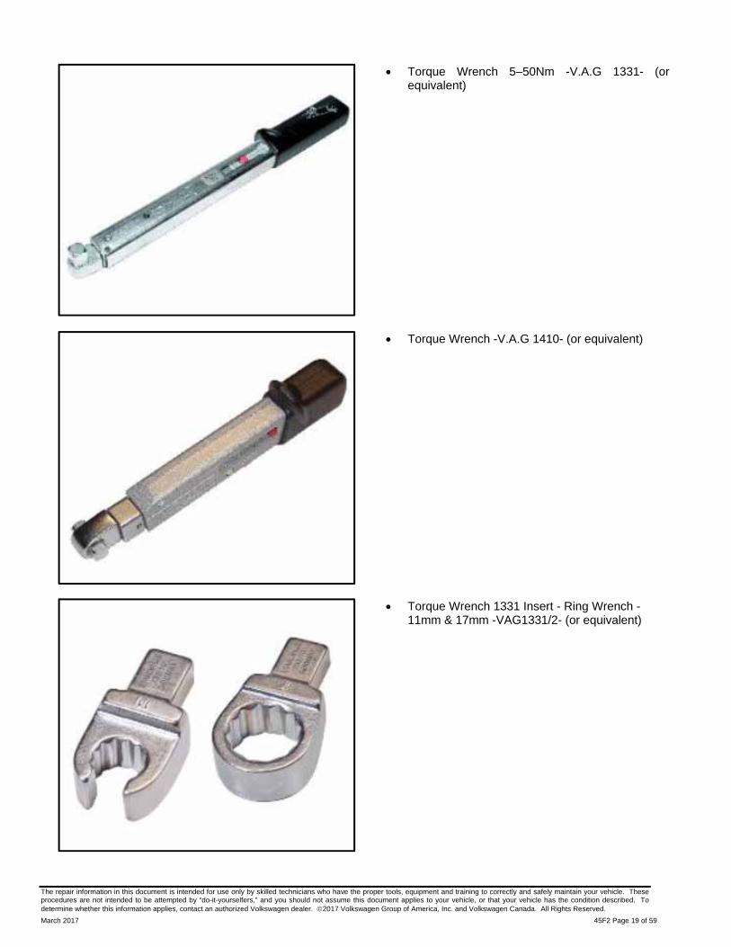
Torque Wrench 5–50Nm -V.A.G 1331- (or equivalent)
Torque Wrench -V.A.G 1410- (or equivalent)
Torque Wrench 1331 Insert - Ring Wrench - 11mm & 17mm -VAG1331/2- (or equivalent)

The repair information in this document is intended for use only by skilled technicians who have the proper tools, equipment and training to correctly and safely maintain your vehicle. These procedures are not intended to be attempted by “do-it-yourselfers,” and you should not assume this document applies to your vehicle, or that your vehicle has the condition described. To determine whether this information applies, contact an authorized Volkswagen dealer. 2017 Volkswagen Group of America, Inc. and Volkswagen Canada. All Rights Reserved.
March 2017 45F2 Page 20 of 59
Brake Pedal Actuator -V.A.G 1869/2-
Engine Bung Set –VAS6122- (or equivalent)
Brake Charger/Bleeder Unit -VAS 5234-

The repair information in this document is intended for use only by skilled technicians who have the proper tools, equipment and training to correctly and safely maintain your vehicle. These procedures are not intended to be attempted by “do-it-yourselfers,” and you should not assume this document applies to your vehicle, or that your vehicle has the condition described. To determine whether this information applies, contact an authorized Volkswagen dealer. 2017 Volkswagen Group of America, Inc. and Volkswagen Canada. All Rights Reserved.
March 2017 45F2 Page 21 of 59
Puller - Wiper Arm Kit - Puller 1 -T10369/1-
Disconnect Battery:
Switch off ignition and remove ignition key.
Open the locking mechanism <arrow> and remove the battery housing cover.
NOTE
Before disconnecting the battery, verify the wipers are in the park position.
Loosen the nut <1>.
Remove and isolate the battery ground cable terminal from the battery terminal.
NOTE
Before disconnecting the battery, it is recommended to record the customer’s radio presets so they can be restored before returning vehicle to the customer.
Continue to Section F for vehicles with a diesel engine.
Continue to next step for vehicles with a gas engine.

The repair information in this document is intended for use only by skilled technicians who have the proper tools, equipment and training to correctly and safely maintain your vehicle. These procedures are not intended to be attempted by “do-it-yourselfers,” and you should not assume this document applies to your vehicle, or that your vehicle has the condition described. To determine whether this information applies, contact an authorized Volkswagen dealer. 2017 Volkswagen Group of America, Inc. and Volkswagen Canada. All Rights Reserved.
March 2017 45F2 Page 22 of 59
Remove Engine Cover:
For 5 cylinder gas engines:
o Open clamp <2> and disconnect intake hose.
o If equipped, disconnect the connector <1> and remove.
o Remove the screws <3> and the intake hose.
Pull the cover out first at the front in direction of <arrow 1>, then at the right rear in direction of <arrow 2> and finally at the left rear in direction of <arrow 3>.
Carefully swivel engine cover out starting at rear area.
Continue to Section G
For 4 cylinder TSI engines:
o Remove the engine cover upward from the attaching points <arrows>.
o Open the clamp and remove the air guide hose from the air filter.

The repair information in this document is intended for use only by skilled technicians who have the proper tools, equipment and training to correctly and safely maintain your vehicle. These procedures are not intended to be attempted by “do-it-yourselfers,” and you should not assume this document applies to your vehicle, or that your vehicle has the condition described. To determine whether this information applies, contact an authorized Volkswagen dealer. 2017 Volkswagen Group of America, Inc. and Volkswagen Canada. All Rights Reserved.
March 2017 45F2 Page 23 of 59
Press the release button to disconnect the air duct hose <1>.
Remove the air duct pipe bolt <arrow>.
Loosen hose clamp <2> and remove air duct.
Remove the intake hose between the intermediate pipe and the turbocharger.
Seal the turbocharger with the Engine Bung Set -VAS6122-.
Continue to Section G
For 4 cylinder FSI engines:
o Disconnect the intake tube <arrow 1>.
o Disconnect the electrical connector <arrow 2>.
o Remove the bolts <arrows 3>.
o Pull engine cover upward at the front <arrows> and remove the engine cover/upper air filter housing.
Continue to Section G

The repair information in this document is intended for use only by skilled technicians who have the proper tools, equipment and training to correctly and safely maintain your vehicle. These procedures are not intended to be attempted by “do-it-yourselfers,” and you should not assume this document applies to your vehicle, or that your vehicle has the condition described. To determine whether this information applies, contact an authorized Volkswagen dealer. 2017 Volkswagen Group of America, Inc. and Volkswagen Canada. All Rights Reserved.
March 2017 45F2 Page 24 of 59
Section F – Particulate Filter Disconnect (to gain access to ABS module)
Pull the engine cover at the corners in direction of <arrows> upward out of the mounts.
Remove wiper arms:
o Pry out the caps <arrows> with a screwdriver.
o Remove the underlying nuts <arrows>.
Slide the Puller - Wiper Arm Kit - Puller 1 -T10369/1 <2> arm under the wiper arm <4>.
CAUTION
The windshield wiper shaft can be damaged.
Always use the thrust piece <3> to loosen the windshield wiper arm.
Damage to the wiper shaft is not covered under this action.
Turn the pressure bolt <1> on the Puller - Wiper Arm Kit - Puller 1 -T10369/1- clockwise until the thrust piece <3> makes contact with the wiper shaft. Turn the pressure bolt <1> on the Puller - Wiper Arm Kit - Puller 1 -T10369/1- clockwise with a hex socket wrench until the wiper arm <4> comes loose off the shaft.

The repair information in this document is intended for use only by skilled technicians who have the proper tools, equipment and training to correctly and safely maintain your vehicle. These procedures are not intended to be attempted by “do-it-yourselfers,” and you should not assume this document applies to your vehicle, or that your vehicle has the condition described. To determine whether this information applies, contact an authorized Volkswagen dealer. 2017 Volkswagen Group of America, Inc. and Volkswagen Canada. All Rights Reserved.
March 2017 45F2 Page 25 of 59
Remove the Puller - Wiper Arm Kit - Puller 1 -T10369/1- and the wiper arm.
CAUTION
Never use a tool (wedge) to pry off the plenum chamber cover. The window glass could be damaged and could crack later. Damage to the windshield or plenum chamber cover is not covered under this action.
Pull off plenum chamber seal <4> from the entire length of facing wall <2> of plenum chamber.
Pull out plenum chamber cover <1> starting at right carefully upward from binding profile <5>.
Remove bolt <4> and nut <2>.
Pull plenum chamber bulkhead upward and remove from the vehicle.
The repair information in this document is intended for use only by skilled technicians who have the proper tools, equipment and training to correctly and safely maintain your vehicle. These procedures are not intended to be attempted by “do-it-yourselfers,” and you should not assume this document applies to your vehicle, or that your vehicle has the condition described. To determine whether this information applies, contact an authorized Volkswagen dealer. 2017 Volkswagen Group of America, Inc. and Volkswagen Canada. All Rights Reserved.
March 2017 45F2 Page 26 of 59
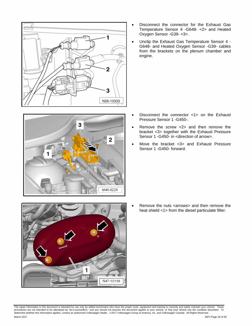
Disconnect the connector for the Exhaust Gas Temperature Sensor 4 -G648- <2> and Heated Oxygen Sensor -G39- <3>.
Unclip the Exhaust Gas Temperature Sensor 4 -G648- and Heated Oxygen Sensor -G39- cables from the brackets on the plenum chamber and engine.
Disconnect the connector <1> on the Exhaust Pressure Sensor 1 -G450-.
Remove the screw <2> and then remove the bracket <3> together with the Exhaust Pressure Sensor 1 -G450- in <direction of arrow>.
Move the bracket <3> and Exhaust Pressure Sensor 1 -G450- forward.
Remove the nuts <arrows> and then remove the heat shield <1> from the diesel particulate filter.

The repair information in this document is intended for use only by skilled technicians who have the proper tools, equipment and training to correctly and safely maintain your vehicle. These procedures are not intended to be attempted by “do-it-yourselfers,” and you should not assume this document applies to your vehicle, or that your vehicle has the condition described. To determine whether this information applies, contact an authorized Volkswagen dealer. 2017 Volkswagen Group of America, Inc. and Volkswagen Canada. All Rights Reserved.
March 2017 45F2 Page 27 of 59
Remove the particulate filter bracket bolt <1>.
Raise the vehicle.
Remove bolts <2> and <3>.
Pull noise insulation <1> back, out of front bumper cover.

The repair information in this document is intended for use only by skilled technicians who have the proper tools, equipment and training to correctly and safely maintain your vehicle. These procedures are not intended to be attempted by “do-it-yourselfers,” and you should not assume this document applies to your vehicle, or that your vehicle has the condition described. To determine whether this information applies, contact an authorized Volkswagen dealer. 2017 Volkswagen Group of America, Inc. and Volkswagen Canada. All Rights Reserved.
March 2017 45F2 Page 28 of 59
Loosen and remove the turbocharger/particulate filter clamp <1>.
NOTE
Position of clamp <1> may vary. If necessary, use 5 mm bit with ball head (e.g. T10058).
Remove clamp <3> between EGR filter and Particulate filter.
Remove exhaust system bracket from subframe <arrows>.

The repair information in this document is intended for use only by skilled technicians who have the proper tools, equipment and training to correctly and safely maintain your vehicle. These procedures are not intended to be attempted by “do-it-yourselfers,” and you should not assume this document applies to your vehicle, or that your vehicle has the condition described. To determine whether this information applies, contact an authorized Volkswagen dealer. 2017 Volkswagen Group of America, Inc. and Volkswagen Canada. All Rights Reserved.
March 2017 45F2 Page 29 of 59
Remove the bolts <1> and remove the drive axle cover <2>.
Loosen the double clamp on the exhaust pipe and push it toward the rear (if required).
Remove and discard bolts <arrows> and remove right drive axle from transmission.
Rest drive axle on front subframe.
NOTE
The drive axle does not need to be removed from the vehicle or unbolted from the wheel hub.

The repair information in this document is intended for use only by skilled technicians who have the proper tools, equipment and training to correctly and safely maintain your vehicle. These procedures are not intended to be attempted by “do-it-yourselfers,” and you should not assume this document applies to your vehicle, or that your vehicle has the condition described. To determine whether this information applies, contact an authorized Volkswagen dealer. 2017 Volkswagen Group of America, Inc. and Volkswagen Canada. All Rights Reserved.
March 2017 45F2 Page 30 of 59
Loosen bolt <4>, but do not remove.
NOTE
Loosening this bolt now is required due to the tightening sequence to be performed during re-assembly.
TIP
Use a commercially available 13 mm combination wrench with a 15° offset and a total length of 140 mm to loosen nut <4>.
Remove the nuts <1> and lower the particulate filter.
Remove the nuts <2> and remove the particulate filter bracket <3>.
Lower the particulate filter just enough so that it touches the steering gear.
CAUTION
Ensure sensor wiring harnesses are not damaged or pinched when lowering particulate filter.
Continue to Section G
The repair information in this document is intended for use only by skilled technicians who have the proper tools, equipment and training to correctly and safely maintain your vehicle. These procedures are not intended to be attempted by “do-it-yourselfers,” and you should not assume this document applies to your vehicle, or that your vehicle has the condition described. To determine whether this information applies, contact an authorized Volkswagen dealer. 2017 Volkswagen Group of America, Inc. and Volkswagen Canada. All Rights Reserved.
March 2017 45F2 Page 31 of 59
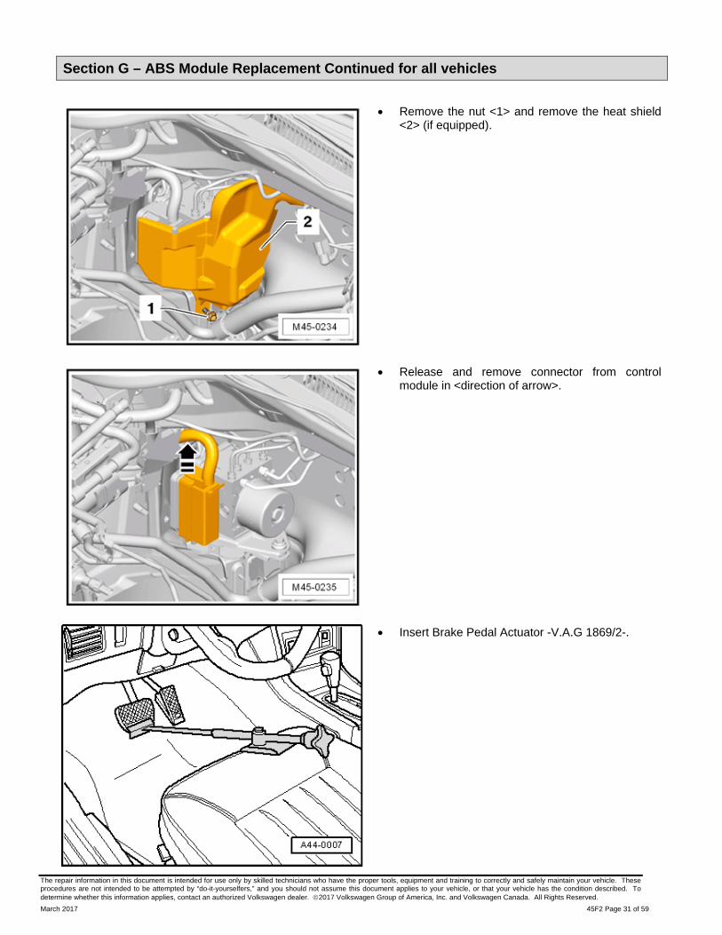
Section G – ABS Module Replacement Continued for all vehicles
Remove the nut <1> and remove the heat shield <2> (if equipped).
Release and remove connector from control module in <direction of arrow>.
Insert Brake Pedal Actuator -V.A.G 1869/2-.

The repair information in this document is intended for use only by skilled technicians who have the proper tools, equipment and training to correctly and safely maintain your vehicle. These procedures are not intended to be attempted by “do-it-yourselfers,” and you should not assume this document applies to your vehicle, or that your vehicle has the condition described. To determine whether this information applies, contact an authorized Volkswagen dealer. 2017 Volkswagen Group of America, Inc. and Volkswagen Canada. All Rights Reserved.
March 2017 45F2 Page 32 of 59
Remove bleeder valve caps <1> from the left front and left rear brake bleeder valves.
Attach a bleed hose to the left front and left rear brake caliper breather valves.
NOTE
Use a suitable bleeder hose. It must fit tightly on the breather valve so that no air can get into the brake system.
Position the opposite ends of the bleed hoses into an appropriate container.
Open the breather valves to the left front and left rear brake caliper.
Push the brake pedal down at least 60 mm using the Brake Pedal Actuator -VAG1869/2-.
Close the left front and left rear breather valves after pressing down on the brake pedal.
CAUTION
Do not remove the Brake Pedal Actuator -VAG1869/2-.
NOTE
When removing the brake lines from the ABS module, the threaded holes in the hydraulic unit must be sealed. The new ABS module includes sealing plugs. The black plugs are for threaded holes <A and B> in the work procedure and the clear plugs are for threaded holes <1 through 4> in the work procedure.

The repair information in this document is intended for use only by skilled technicians who have the proper tools, equipment and training to correctly and safely maintain your vehicle. These procedures are not intended to be attempted by “do-it-yourselfers,” and you should not assume this document applies to your vehicle, or that your vehicle has the condition described. To determine whether this information applies, contact an authorized Volkswagen dealer. 2017 Volkswagen Group of America, Inc. and Volkswagen Canada. All Rights Reserved.
March 2017 45F2 Page 33 of 59
NOTE
Make sure that brake fluid does not come in contact with the terminals.
Clean the brake line fittings with a suitable cleaner.
It is not permitted to use any cleaning products which contain mineral oil, such as oils, greases etc.
WARNING
Do not bend the brake lines near the hydraulic unit.
To protect against escaping brake fluid, place a lint-free rag in the area under the control module and hydraulic unit.
First, mark the installed position of both brake lines from master cylinder <A and B> and remove from the hydraulic unit.
Seal threaded holes in the hydraulic unit with black sealing plugs (provided with new ABS module) and cover exposed brake lines using a clean plastic bag to prevent leaking brake fluid.
Mark the installed position of brake lines (brake calipers) <1 through 4> and remove.
Seal threaded holes in the hydraulic unit with clear sealing plugs (provided with new ABS module) and cover exposed brake lines using a clean plastic bag to prevent leaking brake fluid.
Remove bolt <arrow> from the bracket.
Remove the hydraulic unit, the control module and the side retainer in <direction of arrow> from the bracket rubber insulation.

The repair information in this document is intended for use only by skilled technicians who have the proper tools, equipment and training to correctly and safely maintain your vehicle. These procedures are not intended to be attempted by “do-it-yourselfers,” and you should not assume this document applies to your vehicle, or that your vehicle has the condition described. To determine whether this information applies, contact an authorized Volkswagen dealer. 2017 Volkswagen Group of America, Inc. and Volkswagen Canada. All Rights Reserved.
March 2017 45F2 Page 34 of 59
Remove bolts <1> and separate the hyrdraulic unit from the bracket.
TIP
Remove the bracket from the hydraulic unit while the assembly is still in the engine compartment.
Remove the hydraulic unit and the control module from the vehicle.
WARNING
On a disconnected control module the circuit board is exposed.
No moisture or particles of dirt must penetrate into the interior of control module.
See Appendix C for ESD workplace instructions.
Set hydraulic unit with control module facing upward onto the ESD workmat.

The repair information in this document is intended for use only by skilled technicians who have the proper tools, equipment and training to correctly and safely maintain your vehicle. These procedures are not intended to be attempted by “do-it-yourselfers,” and you should not assume this document applies to your vehicle, or that your vehicle has the condition described. To determine whether this information applies, contact an authorized Volkswagen dealer. 2017 Volkswagen Group of America, Inc. and Volkswagen Canada. All Rights Reserved.
March 2017 45F2 Page 35 of 59
Remove and discard bolts <arrows>.
Remove the ABS Control Module -J104- from the ABS Hydraulic Unit -N55- in the direction of <arrow> without tilting it.
Carefully remove and discard all the seals from the valve domes on the ABS Hydraulic Unit -N55-.
NOTE
It is imperative that a clean environment is present and that the ABS Hydraulic Unit and ABS Control module are thoroughly cleaned before separating the units. The cleanliness level should be maintained throughout the remainder of the repair to avoid contaminating the brake hydraulic system.
It is not permitted to use any cleaning products which contain mineral oil, such as oils, greases etc.

The repair information in this document is intended for use only by skilled technicians who have the proper tools, equipment and training to correctly and safely maintain your vehicle. These procedures are not intended to be attempted by “do-it-yourselfers,” and you should not assume this document applies to your vehicle, or that your vehicle has the condition described. To determine whether this information applies, contact an authorized Volkswagen dealer. 2017 Volkswagen Group of America, Inc. and Volkswagen Canada. All Rights Reserved.
March 2017 45F2 Page 36 of 59
Install new sealing rings <A> slightly over the valve domes as shown.
WARNING
On a disconnected control module the circuit board is exposed.
No moisture or particles of dirt must penetrate into the interior of control module.
Place the new ABS Control Module -J104- on the ABS Hydraulic Unit -N55- without tilting it.
Part Number Part Description
1K0907375AP ABS Control Module
OR
1K0907375AN ABS Control Module
NOTE
When ordering a new ABS Control Module, refer to ETKA to ensure the correct part number is ordered.
NOTE
Once installed, the sealing rings will be brought into their end position.

The repair information in this document is intended for use only by skilled technicians who have the proper tools, equipment and training to correctly and safely maintain your vehicle. These procedures are not intended to be attempted by “do-it-yourselfers,” and you should not assume this document applies to your vehicle, or that your vehicle has the condition described. To determine whether this information applies, contact an authorized Volkswagen dealer. 2017 Volkswagen Group of America, Inc. and Volkswagen Canada. All Rights Reserved.
March 2017 45F2 Page 37 of 59
Install and torque new bolts <arrows> in a cross pattern to 2 Nm ± 0.8 Nm.
NOTE
New bolts are included with the new ABS Control Module.
Woking inside the engine compartment, install the bracket to the ABS Hydraulic Unit -N55- and torque the bolts <1> to 8 Nm.

The repair information in this document is intended for use only by skilled technicians who have the proper tools, equipment and training to correctly and safely maintain your vehicle. These procedures are not intended to be attempted by “do-it-yourselfers,” and you should not assume this document applies to your vehicle, or that your vehicle has the condition described. To determine whether this information applies, contact an authorized Volkswagen dealer. 2017 Volkswagen Group of America, Inc. and Volkswagen Canada. All Rights Reserved.
March 2017 45F2 Page 38 of 59
Install the ABS Hydraulic Unit -N55- with the ABS Control Module -J104- and the bracket sideways into the rubber bushings on the console.
NOTE
When installing the ABS Control Module, make sure the rubber insulation does not push out of the bracket. Silicone spray can be used to ease installation. After installing, make sure the hydraulic unit and the control module are secure, otherwise malfunctions will register.
Install the bolt <arrow> and torque to 8 Nm.
Remove sealing plugs for brake lines <1 through 4>, install the brake lines and torque to 14 Nm.
Remove sealing plugs for brake lines <A and B>, install the brake lines and torque to 14 Nm.
Install heat shield <2> (if equipped) and torque bolt <1> to 8 Nm.
Continue to Section H for diesel vehicles.
Continue to Section I for gasoline vehicles.

The repair information in this document is intended for use only by skilled technicians who have the proper tools, equipment and training to correctly and safely maintain your vehicle. These procedures are not intended to be attempted by “do-it-yourselfers,” and you should not assume this document applies to your vehicle, or that your vehicle has the condition described. To determine whether this information applies, contact an authorized Volkswagen dealer. 2017 Volkswagen Group of America, Inc. and Volkswagen Canada. All Rights Reserved.
March 2017 45F2 Page 39 of 59
Section H – Reconnect Particulate Filter
Position new clamp and gasket onto particulate filter, but do not tighten clamp at this time .
Part Number Part Description
1K0253725 Clamp
1K0253115T Gasket
Install particulate filter bracket <3> with nuts <2> but do not tighten at this time.
Postion particulate filter onto bracket <3>.
Install nuts <1>, but do not tighten at this time.
Install new clamp and gasket between EGR filter and Particulate filter.
Part Number Part Description
1K0253725E Clamp
1K0253115AG Gasket
Snug the clamp bolt by hand, but do not tighten at this time.

The repair information in this document is intended for use only by skilled technicians who have the proper tools, equipment and training to correctly and safely maintain your vehicle. These procedures are not intended to be attempted by “do-it-yourselfers,” and you should not assume this document applies to your vehicle, or that your vehicle has the condition described. To determine whether this information applies, contact an authorized Volkswagen dealer. 2017 Volkswagen Group of America, Inc. and Volkswagen Canada. All Rights Reserved.
March 2017 45F2 Page 40 of 59
Install bolt <5> loosely by hand.
Particulate filter and bracket must be able to move.
Tighten fasteners in the following order:
1 Tighten clamp <1> 7 Nm 2 Tighten nuts <2> 23 Nm 3 Tighten nuts <3> 23 Nm 4 Tighten nut <4> 23 Nm 5 Tighten nut <5> 23 Nm 6 Tighten nut <6> 3.5 Nm
NOTE
Due to restricted space, the nut <2> cannot be reached with a torque wrench. Use a commercially available 13 mm combination wrench with a 15° offset and a total length of 140 mm.
NOTE
RISK of Exhaust Leak!
Tightening sequence must be followed. Failure to follow this sequence can result in an exhaust leak. Diagnosis or repair of faults associated with an exhaust leak will not be covered by this action.
Install heat shield <1> and torque nuts to 10 Nm.
The repair information in this document is intended for use only by skilled technicians who have the proper tools, equipment and training to correctly and safely maintain your vehicle. These procedures are not intended to be attempted by “do-it-yourselfers,” and you should not assume this document applies to your vehicle, or that your vehicle has the condition described. To determine whether this information applies, contact an authorized Volkswagen dealer. 2017 Volkswagen Group of America, Inc. and Volkswagen Canada. All Rights Reserved.
March 2017 45F2 Page 41 of 59
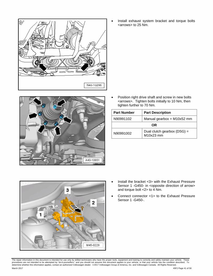
Install exhaust system bracket and torque bolts <arrows> to 25 Nm.
Position right drive shaft and screw in new bolts <arrows>. Tighten bolts initially to 10 Nm, then tighten further to 70 Nm.
Part Number Part Description
N90991102 Manual gearbox = M10x52 mm
OR
N90991002 Dual clutch gearbox (DSG) = M10x23 mm
Install the bracket <3> with the Exhaust Pressure Sensor 1 -G450- in <opposite direction of arrow> and torque bolt <2> to 4 Nm.
Connect connector <1> to the Exhaust Pressure Sensor 1 -G450-.

The repair information in this document is intended for use only by skilled technicians who have the proper tools, equipment and training to correctly and safely maintain your vehicle. These procedures are not intended to be attempted by “do-it-yourselfers,” and you should not assume this document applies to your vehicle, or that your vehicle has the condition described. To determine whether this information applies, contact an authorized Volkswagen dealer. 2017 Volkswagen Group of America, Inc. and Volkswagen Canada. All Rights Reserved.
March 2017 45F2 Page 42 of 59
Install the Exhaust Gas Temperature Sensor 4 -G648- and Heated Oxygen Sensor -G39- into the brackets on the plenum chamber and engine.
Connect the connector for the Exhaust Gas Temperature Sensor 4 -G648- <2> and Heated Oxygen Sensor -G39- <3>.
Install noise insulation <1>. Torque bolts <2> to 2 Nm and bolts <3> to 6 Nm.

The repair information in this document is intended for use only by skilled technicians who have the proper tools, equipment and training to correctly and safely maintain your vehicle. These procedures are not intended to be attempted by “do-it-yourselfers,” and you should not assume this document applies to your vehicle, or that your vehicle has the condition described. To determine whether this information applies, contact an authorized Volkswagen dealer. 2017 Volkswagen Group of America, Inc. and Volkswagen Canada. All Rights Reserved.
March 2017 45F2 Page 43 of 59
Installl plenum chamber bulkhead. When installing bulkhead, make sure seal <3> is seated correctly.
Install bolt <4> and nut <2> and torque to 8 Nm.
Spray binding profile <5> with soap solution so that plenum chamber cover <1> can be pressed in more easily.
Place plenum chamber cover <1> onto binding profile <1> and engage it with binding profile <5> starting from center using light pressure.
Install plenum chamber seal <4>.
CAUTION
Striking the plenum chamber cover can cause cracks in the windshield.
Damage to the plenum chamber cover is not covered under this action.

The repair information in this document is intended for use only by skilled technicians who have the proper tools, equipment and training to correctly and safely maintain your vehicle. These procedures are not intended to be attempted by “do-it-yourselfers,” and you should not assume this document applies to your vehicle, or that your vehicle has the condition described. To determine whether this information applies, contact an authorized Volkswagen dealer. 2017 Volkswagen Group of America, Inc. and Volkswagen Canada. All Rights Reserved.
March 2017 45F2 Page 44 of 59
Turn on the ignition and then switch the windshield wipers on and off so that the Windshield Wiper Motor -V- goes into its park position.
Mount both wiper arms on the wiper arm shafts and install the nuts <arrows> hand-tight.
Adjust the wiper blade park position.
o For the driver side: distance <A> between tips of wiper lips and upper edge of plenum chamber cover must be 10 mm.
o For the passenger side: distance <B> between tips of wiper lips and upper edge of plenum chamber cover must be 10 mm.
Torque wiper arm nuts to 20 Nm and install protective caps.
Continue to Section I
The repair information in this document is intended for use only by skilled technicians who have the proper tools, equipment and training to correctly and safely maintain your vehicle. These procedures are not intended to be attempted by “do-it-yourselfers,” and you should not assume this document applies to your vehicle, or that your vehicle has the condition described. To determine whether this information applies, contact an authorized Volkswagen dealer. 2017 Volkswagen Group of America, Inc. and Volkswagen Canada. All Rights Reserved.
March 2017 45F2 Page 45 of 59
Section I – ABS Module Replacement, continued (all vehicles)
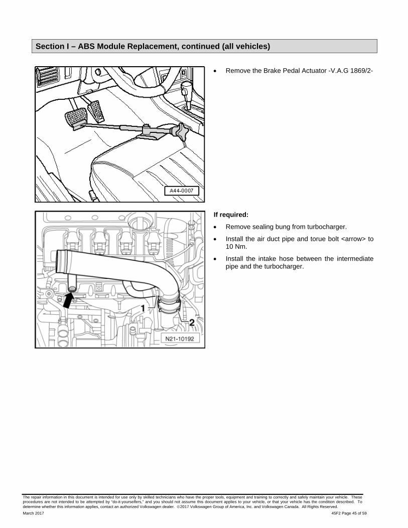
Remove the Brake Pedal Actuator -V.A.G 1869/2-
If required:
Remove sealing bung from turbocharger.
Install the air duct pipe and torue bolt <arrow> to 10 Nm.
Install the intake hose between the intermediate pipe and the turbocharger.

The repair information in this document is intended for use only by skilled technicians who have the proper tools, equipment and training to correctly and safely maintain your vehicle. These procedures are not intended to be attempted by “do-it-yourselfers,” and you should not assume this document applies to your vehicle, or that your vehicle has the condition described. To determine whether this information applies, contact an authorized Volkswagen dealer. 2017 Volkswagen Group of America, Inc. and Volkswagen Canada. All Rights Reserved.
March 2017 45F2 Page 46 of 59
Install engine cover.
Connect the battery ground cable terminal by hand to the battery negative terminal.
Torque the nut <1> to 6 Nm.
Store previously recorded radio presets (if necessary)
Set clock to local time.
Activate the power window regulator one-touch up/down function.
NOTE
Bleeding the braking system on vehicles with ABS is carried out as for vehicles with conventional braking systems.
Only use new brake fluid conforming to VW standard (VW 501 14).
Genuine VW/Audi brake fluid conforms to this specification.
Due to its caustic nature, brake fluid must never be brought into contact with paint.
Brake fluid is hygroscopic, meaning that it absorbs moisture from the surrounding air, and must therefore be stored in air-tight containers.
Rinse off spills, by using plenty of water.
Attach the GRX3000VAS Tester/Charger (or equivalent) to the vehicle battery.
Turn the igniton on.
TIP
Leaving the ignition on for a period of time before performing ABS Module basic settings may reduce problems during the basic setting test plans.
Remove all four wheels.
Connect Brake Charger/Bleeder Unit -VAS 5234- and perform Pre-Bleeding of the brake system.
NOTE
There must be a positive pressure of 2 bar when bleeding the hydraulic unit.
With bleeder bottle hoses attached, leave bleeder valves open long enough that brake fluid exits without bubbles using the following bleeding sequence:

The repair information in this document is intended for use only by skilled technicians who have the proper tools, equipment and training to correctly and safely maintain your vehicle. These procedures are not intended to be attempted by “do-it-yourselfers,” and you should not assume this document applies to your vehicle, or that your vehicle has the condition described. To determine whether this information applies, contact an authorized Volkswagen dealer. 2017 Volkswagen Group of America, Inc. and Volkswagen Canada. All Rights Reserved.
March 2017 45F2 Page 47 of 59
o Bleed left front and right front brake caliper together simultaneously.
o Bleed left rear and right rear brake caliper together simultaneously.
Start the ODIS program.
Hydraulic unit must now be bled once more via Guided Function test:
o Select operating mode “Diagnosis”, scroll down and right click on Address Word 0003/ABS Control Module, select Guided Functions, select “Basic setting/bleeding brake system” <arrow> and follow on screen directions.
After basic setting has been performed, remove the battery charger.
TIP
The test plan for bleeding the brakes should be under Guided Functions. In the event it is not, it should be found by selecting the self test under the test plan tab.
NOTE
There must be a positive pressure of 1 bar when performing the normal brake bleeding procedure.
After Pre-Bleeding has been completed, the brake system is then bled normally using the Brake Charger/Bleeder Unit -VAS 5234- using the following bleeding sequence:
1. Front left brake caliper
2. Right front brake caliper
3. Left rear brake caliper
4. Right rear brake caliper
With bleeder bottle hose attached, leave bleeder valve open long enough that brake fluid exits without bubbles.
NOTE
The Post-Bleeding procedure must be performed 5 times per brake caliper.
Perform the Post-Bleeding procedure using a second technician:
o Bleeding sequence:

The repair information in this document is intended for use only by skilled technicians who have the proper tools, equipment and training to correctly and safely maintain your vehicle. These procedures are not intended to be attempted by “do-it-yourselfers,” and you should not assume this document applies to your vehicle, or that your vehicle has the condition described. To determine whether this information applies, contact an authorized Volkswagen dealer. 2017 Volkswagen Group of America, Inc. and Volkswagen Canada. All Rights Reserved.
March 2017 45F2 Page 48 of 59
1. Front left brake caliper.
2. Right front brake caliper.
3. Left rear brake caliper.
4. Right rear brake caliper.
o Depress brake pedal forcefully and hold.
o Open bleeder valve at brake caliper.
o Press brake pedal down onto stop.
o Close bleeder screw with pedal depressed.
o Release brake pedal slowly.
Torque bleeder valves to 10 Nm and install brake bleeder valve caps on all four brake bleeder valves.
Install all four wheels and torque lug bolts to 120 Nm.
Lower the vehicle.
NOTE
The following steps should be followed in the order listed to minimize problems during the basic setting test plans.
These test plans can be troublesome and may have to be repeated. The time allowed to replace the ABS Control Module includes GFF time and should be sufficient to replace the ABS Control Module AND complete all of the test plans. Additional GFF time will not be covered under this Campaign.
Start the ODIS program.
CAUTION
Do not used a saved ODIS session. Perform a complete new scan of the vehicle. Starting a saved ODIS session during the ABS Module replacement will result in errors when performing coding and basic settings of the new ABS Module.
NOTE
The new ABS modules do not contain the safety defect and do not require the detection software. Performing the SVM at this point does not change the software.
The repair information in this document is intended for use only by skilled technicians who have the proper tools, equipment and training to correctly and safely maintain your vehicle. These procedures are not intended to be attempted by “do-it-yourselfers,” and you should not assume this document applies to your vehicle, or that your vehicle has the condition described. To determine whether this information applies, contact an authorized Volkswagen dealer. 2017 Volkswagen Group of America, Inc. and Volkswagen Canada. All Rights Reserved.
March 2017 45F2 Page 49 of 59
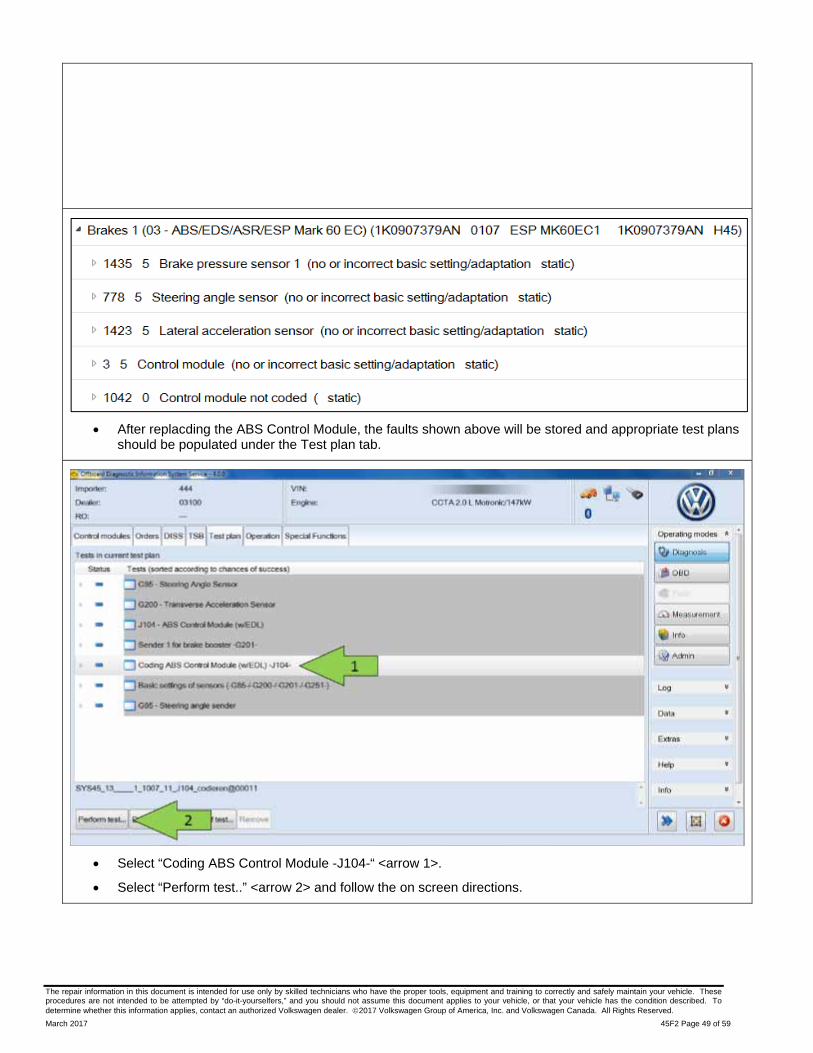
After replacding the ABS Control Module, the faults shown above will be stored and appropriate test plans should be populated under the Test plan tab.
Select “Coding ABS Control Module -J104-“ <arrow 1>.
Select “Perform test..” <arrow 2> and follow the on screen directions.

The repair information in this document is intended for use only by skilled technicians who have the proper tools, equipment and training to correctly and safely maintain your vehicle. These procedures are not intended to be attempted by “do-it-yourselfers,” and you should not assume this document applies to your vehicle, or that your vehicle has the condition described. To determine whether this information applies, contact an authorized Volkswagen dealer. 2017 Volkswagen Group of America, Inc. and Volkswagen Canada. All Rights Reserved.
March 2017 45F2 Page 50 of 59
After coding is completed, this screen may be displayed. DO NOT move forward in this test plan.
Select “Cancel test” <arrow>.
Remove the battery charger, close the hood.

The repair information in this document is intended for use only by skilled technicians who have the proper tools, equipment and training to correctly and safely maintain your vehicle. These procedures are not intended to be attempted by “do-it-yourselfers,” and you should not assume this document applies to your vehicle, or that your vehicle has the condition described. To determine whether this information applies, contact an authorized Volkswagen dealer. 2017 Volkswagen Group of America, Inc. and Volkswagen Canada. All Rights Reserved.
March 2017 45F2 Page 51 of 59
NOTE
IF online coding is not successful:
Right click on Address 0003 (ABS Control Module), select “Control Module OBD” and then select “Coding”.
Enter the previously recorded coding:
1. Left click on the empty box in the Hex Input column <arrow 1> for the appropriate coding byte.
2. Enter the previously recorded Hex value <arrow 2>.
3. Select Apply <arrow 3>.
4. Repeat for each coding byte.
5. Once all coding bytes have been entered, select Apply in the bottom left <arrow 4>.
After coding is complete, an ignition cycle will need to be performed.
Clear the coding fault stored in the ABS Control Module.

The repair information in this document is intended for use only by skilled technicians who have the proper tools, equipment and training to correctly and safely maintain your vehicle. These procedures are not intended to be attempted by “do-it-yourselfers,” and you should not assume this document applies to your vehicle, or that your vehicle has the condition described. To determine whether this information applies, contact an authorized Volkswagen dealer. 2017 Volkswagen Group of America, Inc. and Volkswagen Canada. All Rights Reserved.
March 2017 45F2 Page 52 of 59
Select “Basic settings of sensors (-G85-/-G200-/-G201-/-G251-)” <arrow 1>.
TIP
The -G251- is only installed on all wheel drive vehicles. However, the test plan step will need to be completed. When asked if the vehicle has any of the PR codes listed, select “NO”.
Select “Perform test..” <arrow 2> and perform the basic settings of all four sensors.
Once the test plan is completed, the faults for each of the sensors can be cleared using Control Module OBD.
Do not continue if the fault for “Brake pressure sensor 1 (G201)” is still stored. This fault must be cleared in order to set the basic settings of the intake and disconnecting valves.

The repair information in this document is intended for use only by skilled technicians who have the proper tools, equipment and training to correctly and safely maintain your vehicle. These procedures are not intended to be attempted by “do-it-yourselfers,” and you should not assume this document applies to your vehicle, or that your vehicle has the condition described. To determine whether this information applies, contact an authorized Volkswagen dealer. 2017 Volkswagen Group of America, Inc. and Volkswagen Canada. All Rights Reserved.
March 2017 45F2 Page 53 of 59
Once the -G85-/-G200-/-G201-/-G251- faults are cleared, select “Basic setting of intake valves” <arrow 1>.
Open the hood.
Select “Perform test..” <arrow 2> and follow on screen instructions.
TIP
The test plans for setting the intake and disconnecting valves should populate in the test plan tab. If they do not, perform the “J104 – ABS Control Module (w/EDL)” test plan. If the intake and disconnecting valve test plans are still not populated, they can be found by selecting the self test under the test plan tab.

The repair information in this document is intended for use only by skilled technicians who have the proper tools, equipment and training to correctly and safely maintain your vehicle. These procedures are not intended to be attempted by “do-it-yourselfers,” and you should not assume this document applies to your vehicle, or that your vehicle has the condition described. To determine whether this information applies, contact an authorized Volkswagen dealer. 2017 Volkswagen Group of America, Inc. and Volkswagen Canada. All Rights Reserved.
March 2017 45F2 Page 54 of 59
When this message is displayed, STOP!
Cycle the ignition off for 30 seconds.
Turn the ignition back on and now press Complete/Continue.
The test plan for setting the intake valves should now start.
CAUTION
When performing the basic settings of the intake and disconnecting valves, ensure the brake pedal pressure is adjusted slowly and evenly.
NOTE
The screen displayed here is for the disconnecting valves, the message displayed for the intake valves will be the same.
TIP
When performing the basic settings of the intake and disconnecting valves, the ABS Control Module should be kept cool. The basic settings could stall due to high under hood temperatures. It is recommended to leave the hood open and have a fan blowing on the ABS Control Module. If necessary, the ABS Control Module can be cooled with ice.

The repair information in this document is intended for use only by skilled technicians who have the proper tools, equipment and training to correctly and safely maintain your vehicle. These procedures are not intended to be attempted by “do-it-yourselfers,” and you should not assume this document applies to your vehicle, or that your vehicle has the condition described. To determine whether this information applies, contact an authorized Volkswagen dealer. 2017 Volkswagen Group of America, Inc. and Volkswagen Canada. All Rights Reserved.
March 2017 45F2 Page 55 of 59
It is possible that this screen is diplayed after starting the “Basic setting of intake valves” test plan. The following have been found to get the test plan to start:
o Clearing all vehicle system faults using Control Module OBD, cycling the ignition and repeating the test plan.
o Exiting ODIS, rescanning the vehicle and repeating the test plan.
o Shutting the engine off and leaving the ignition turned on for 30 minutes.

The repair information in this document is intended for use only by skilled technicians who have the proper tools, equipment and training to correctly and safely maintain your vehicle. These procedures are not intended to be attempted by “do-it-yourselfers,” and you should not assume this document applies to your vehicle, or that your vehicle has the condition described. To determine whether this information applies, contact an authorized Volkswagen dealer. 2017 Volkswagen Group of America, Inc. and Volkswagen Canada. All Rights Reserved.
March 2017 45F2 Page 56 of 59
Once the Basic setting of intake valves is complete, select “Basic setting of disconnecting valves” <arrow 1>.
Select “Perform test..” <arrow 2>.
An ignition cycle should not have to be performed.
CAUTION
When performing the basic settings of the intake and disconnecting valves, ensure the brake pedal pressure is adjusted slowly and evenly.
Once the intake and disconnecting valve test plans complete, the “Control module basic setting” fault will clear using Control Module OBD.
Exit ODIS completely after clearing faults.
Send the long ODIS log to GFF paperless.
Perform a short road test. During the road test, at least one ABS stop must be performed.
Continue to Section J

The repair information in this document is intended for use only by skilled technicians who have the proper tools, equipment and training to correctly and safely maintain your vehicle. These procedures are not intended to be attempted by “do-it-yourselfers,” and you should not assume this document applies to your vehicle, or that your vehicle has the condition described. To determine whether this information applies, contact an authorized Volkswagen dealer. 2017 Volkswagen Group of America, Inc. and Volkswagen Canada. All Rights Reserved.
March 2017 45F2 Page 57 of 59
Section J – Campaign Completion Label
Install Campaign Completion Label
Fill out and affix Campaign Completion Label, part number CAMP 010 000, next to the vehicle emission control information label.
TIP
Ensure Campaign Completion Label does not cover any existing label(s).
Continue to Section K.
Section K - Parts Return/Disposal
Properly store (retain), destroy or dispose of removed parts in accordance with all state/province and local requirements, unless otherwise indicated and/or requested through the Warranty Parts Portal (WPP).

The repair information in this document is intended for use only by skilled technicians who have the proper tools, equipment and training to correctly and safely maintain your vehicle. These procedures are not intended to be attempted by “do-it-yourselfers,” and you should not assume this document applies to your vehicle, or that your vehicle has the condition described. To determine whether this information applies, contact an authorized Volkswagen dealer. 2017 Volkswagen Group of America, Inc. and Volkswagen Canada. All Rights Reserved.
March 2017 45F2 Page 58 of 59
Appendix A – Warning and Safety Precautions
WARNING
Only use new brake fluid conforming to VW standard (VW 501 14).
Adhere strictly to work sequence when bleeding brake system.
Brake fluid is poisonous. Due to its caustic nature, it must also never be brought into contact with paint.
Brake fluid is hygroscopic, meaning that it absorbs moisture from the surrounding air, and must therefore be stored in air-tight containers.
Wash off any spilled brake fluid with plenty of water.
Appendix B – Antilock Brake System (ABS) Repair Information
CAUTION
Turn off the ignition and disconnect the battery ground cable.
Carry out work before welding with an electric welding tool.
After finishing any work that required opening the brake system, bleed the brake system using the brake charger/bleeder unit -VAS 5234-.
During final road test, carry out at least one ABS-controlled braking operation (appropriate pulsations must be felt at brake pedal).
It is necessary to maintain a high level of cleanliness when working on the ABS system. It is not permitted to use any cleaning products which contain mineral oil, such as oils, greases etc.
Thoroughly clean all unions and the adjacent areas before loosening. Do not use aggressive cleaning agents such as brake cleaner, fuel, thinners or similar chemicals.
Place parts that have been removed on a clean surface and cover.
After removing the control module from the hydraulic unit, use the valve dome transport protection.
Carefully cover or seal open components, if repairs are not carried out immediately. (Use the plugs from repair kit 1H0 698 311 A)
Only use lint-free cloths.
Only unpack replacement parts immediately prior to installation.
Only use parts in their original packaging.
Do not work with compressed air and do not move vehicle while the system is open.
Do not touch the contact surface on the connector, the pressure sensor and control module, as well as the silicone gel.
When painting, electronic control module can be exposed to a maximum temperature of. 95 °C only briefly, and to a maximum of 85 °C for longer periods (approximately 2 hours).
Make sure that brake fluid does not enter harness connectors.

The repair information in this document is intended for use only by skilled technicians who have the proper tools, equipment and training to correctly and safely maintain your vehicle. These procedures are not intended to be attempted by “do-it-yourselfers,” and you should not assume this document applies to your vehicle, or that your vehicle has the condition described. To determine whether this information applies, contact an authorized Volkswagen dealer. 2017 Volkswagen Group of America, Inc. and Volkswagen Canada. All Rights Reserved.
March 2017 45F2 Page 59 of 59
Appendix C – ESD Workplace Instructions
Prior to beginning work, all parts and tools are to be placed on the ESD table mat.
Assemble ESD workplace according to the instructions included with the ESD Workplace.
The wall socket or extension cord used must have a sufficient ground.
CAUTION
The white dots on the wrist strap must be against the skin.