Embed Size (px)
Citation preview

Safety Provisions for the KLT-40S Reactor Plant
Floating Power Unit
I.A. Bylov OKBM Afrikantov, Russian Federation
6th INPRO Dialogue Forum on Global Nuclear Energy Sustainability:
Licensing and Safety Issues for Small and Medium-sized
Nuclear Power Reactors (SMRs)
29 July - 2 August 2013
IAEA Headquarters, Vienna, Austria

2
KLT-40S REACTOR PLANT SAFETY CONCEPT
The KLT-40S reactor plant safety based on:
Defense-in-depth concept
Inherent safety features
Engineered safety features and procedures including:
passive safety systems
self-actuating devices
proven engineering practices and up-to-date design experience
The KLT-40S reactor plant design is developed in compliance with the Russian
laws, regulatory rules for marine nuclear propulsion plants; safety principles
elaborated by the world's nuclear community and reflected in IAEA
recommendations
The safety analysis approach is using two complementary deterministic and
probabilistic methods that provide comprehensiveness and completeness for the
analysis

3
1
2
3
4
5
KLT-40S REACTOR PLANT PHYSICAL SAFETY BARRIERS
1 – FUEL COMPOSITION
2 – FUEL CLADDING
3 – RCS PRESSURE BOUNDARY
4 – PLANT CONTAINMENT
5 – PROTECTIVE ENCLOSURE

4
KLT-40S REACTOR PLANT INHERENT SAFETY FEATURES
Negative reactivity coefficients on fuel and coolant temperature and on
steam density and integral power
High thermal conductivity of the fuel composition defining its relatively low
temperature
Natural circulation in the reactor coolant system and EHRS passive
channels
Insertion of control rods into the core under the force of springs (scram
rods) or gravity (shim rods) in case CRDMs are de-energized
High thermal capacity of the reactor primary coolant system components
and structures
High mechanical stress margin on the reactor coolant system pressure
Compact modular and leaktight design excluding long and large diameter
RCS pipelines

5
EMERGENCY REACTOR SHUTDOWN SYSTEMS
1. Reactor
2. CRDMs
3. Soluble absorber injection system
4. Pressure-actuated electric circuit-breaker
Pressure-actuated electric circuit-breakers de-energizes CRDMs (shutdown the reactor) on:
High reactor coolant pressure
High containment pressure
От УСБ-Т
Soluble absorber
injection system
Electro-mechanical
reactivity control
system
4

6
EMERGENCY HEAT REMOVAL SYSTEMS
Hydraulically
operated air
distributors
Pneumatically-driven
valves in the passive
EHRS channels are
opened on primary
circuit overpressure
1. Reactor
2. Steam generator
3. Main circulation pump
4. Emergency heat
exchangers
5. Purification and residual
heat removal system
6. Auxiliary condenser
6
Two autonomous passive channels for emergency heat removal
Duration of operation without water makeup is
-for two channels, 24 h
- for one channel, 12 h

7
EMERGENCY CORE COOLING SYSTEM
1 Reactor
2 Steam generator
3 Main circulation pump
4 ECCS hydroaccumulator
5 ECCS water tank
6 Recirculation system
Combination of passive and active emergency core cooling subsystems
in the case of a loss of coolant accident
The ECCS water storage tank capacity is 2×10 m3
The ECCS hydroaccumulator capacity is 2×4 m3
1
2
3
4
5
6
4
8
EMERGENCY CONTAINMENT PRESSURE REDUCTION SYSTEM
Passive ECPRS
consists of two
channels
The safety function
is to protect the safety
barrier (plant
containment)
The operation time
is 24 hours
In the case of
LOCA, radioactive
products are retained
within the
containment

9
KLT-40S RESISTANCE TO EXTERNAL HAZARDS
The reactor plant is designed to withstand
the following external hazards:
Marine environmental conditions in
accordance with the requirements of the
Russian Maritime Register of Shipping
Shock resistance of at least 3 g
Unit submersion with the reactor shutdown
and containment integrity ensured
Crash of an aircraft with the mass of 10 t
from the height of 50 m

10
SEVERE ACCIDENT ANALYSIS
THE MOLTEN CORE IS RETAINED INSIDE THE REACTOR VESSEL
Reactor
caisson
Reactor
vessel
Molten core
Cooling water
Some results of the severe accident analysis
The inner surface of the reactor vessel
doesn’t melt
Heat is reliably removed from the outer
surface of the reactor vessel bottom
Despite the high temperature difference,
the mechanical properties of the reactor
vessel material are preserved at the level
that is sufficient to ensure the load
bearing capacity
11
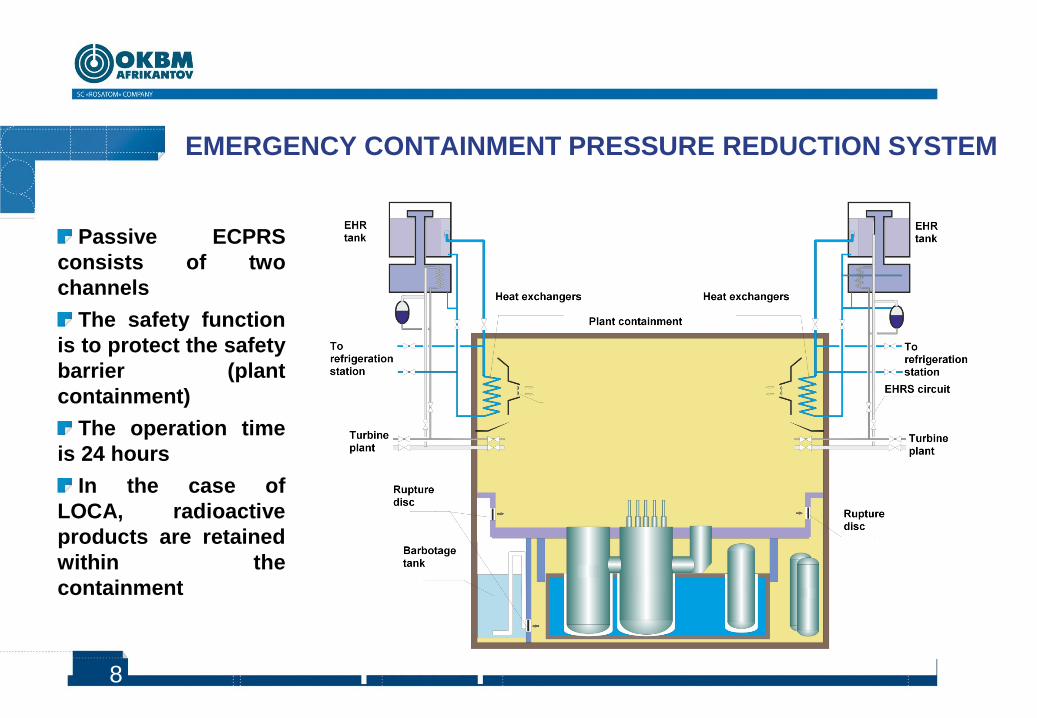
RADIATION AND ENVIRONMENTAL SAFETY
1 km
EMERGENCY PLANNING
ZONE
BUFFER AREA
Under normal operation conditions and in design-basis accidents, the population radiation dose rate does not exceed 0.01% of the natural radiation background
No mandatory evacuation area
Emergency planning zone doesn’t exceed 1 km

12
The objective of the stress analysis is to assess safety of the floating
power unit and to perform a sustainability analysis of the power unit under the
extreme external events that exceed the Russian regulatory requirements
The following postulated events were adopted for the stress analysis of the
floating power unit design:
Earthquake, magnitude 10 on the MSK-64 scale
Tsunami waves, casting the floating power unit ashore
Total blackout with all off-site, auxiliary and emergency power sources
unavailable
Core meltdown in the floating power unit reactors
STRESS ANALYSIS OF THE KLT-40S FLOATING POWER UNIT

13
STRESS ANALYSIS RESULTS
FOR THE KLT-40S FLOATING POWER UNIT
Seismic impact of magnitude 10: no radiological consequences for public and
environment
Tsunami waves, casting the floating power unit ashore: no radiological
consequences for public and environment
Total blackout with all off-site, auxiliary and emergency power sources
unavailable: no radiological consequences for public and environment
Total blackout and core meltdown in the floating power unit reactors:
The reactor remains deeply subcritical
The leaking reactor coolant and non-condensing gases are localized within the
containment
No melting through the reactor pressure vessel with heat being removed by the
passive system of reactor vessel external heat removal

14
KLT-40S floating power unit PSA general goals: To estimate safety level of the power unit
To develop recommendations on technical measures and operational procedures to increase the safety
In Level 1 PSA the design and operation of the unit are analysed in order to identify the sequences of events that lead to core damage and the core damage frequency is estimated
Status of KLT-40S floating power unit PSA : Developed:
PSA Level 1 for internal initiating events for full power operating conditions
PSA Level 1 for low power and shutdown modes
PSA Level 1 for internal hazards (fires and flooding)
PSA Level 1 for external hazards
KLT-40S FLOATING POWER UNIT
PROBABILISTIC SAFETY ASSESSMENT (I)

15
KLT-40S FLOATING POWER UNIT
PROBABILISTIC SAFETY ASSESSMENT (II)
Scope of PSA
Core damage frequency
(1/reactor*year)
PSA Level 1 for internal initiating events for full power
<10-7
PSA Level 1 for low power and shutdown modes
~3· 10-9
PSA Level 1 results
Interrelation between initiating events frequencies
and conditional core damage probability
PROBABILISTIC SAFETY ASSESSMENT LEVEL 1 RESULTS INDICATED THAT KLT-40S
FLOATING POWER UNIT DESIGN IS WELL-BALANCED AND ITS SAFETY LEVEL MEETS
RUSSIAN REGULATORY REQUIREMENTS AND IAEA RECOMMENDATIONS FOR
EXISTING AND FUTURE POWER PLANTS
Recommendations to increase safety were
developed based on PSA results
1.00E+00
1.00E+01
1.00E+02
1.00E+03
1.00E+04
1.00E+05
1.00E+06
1.00E+07
1.00E+08
1.00E+09
1.00E+10
1.00E+11
S1 M2 B2 M1 SS TA TE B3 B1 A1 TP R1
Conditional core damage probability Initiating event frequency
16
Burnakovsky proyezd, 15
Nizhny Novgorod,
603074, Russia
Phone +7 (831)275-40-76,
+7 (831) 275-26-40
Fax +7 (831) 241-87-72
www.okbm.nnov.ru
THANK YOU FOR ATTENTION!