Embed Size (px)
Citation preview

BRANO a.s., 747 41 Hradec nad Moravicí The Czech Republic
tel.:+420/ 553 632 316, 553 632 303
http://www.brano.eu; [email protected]; [email protected]
SAFETY PRINCIPLES, OPERATION AND MAINTENANCE MANUAL
FOR
RACK-AND-LEVER JACK
type RZC, lifting capacity 0,8t; 1,6t; 3,2t; 5t and 6,3t
Read this manual carefully before using this product. This manual contains safety,
installation, operation and maintenance information. Make this manual available to all responsible persons.
Keep for further use !
Edition 5 th
JANUARY 2014 Registration number 1-52184-0-1

2
CONTENT
1 DEFINITION ............................................................................................................ 3
2 INTENDED PURPOSE ............................................................................................ 3
3 SAFETY PRINCIPLES ............................................................................................. 4
3.1 SAFETY SUMMARY ......................................................................................... 4
3.2 SAFETY PRINCIPLES ...................................................................................... 4
4 PACKING, STORAGE AND MANIPULATION ......................................................... 6
4.1 PACKING .......................................................................................................... 6
4.2 STORAGE ........................................................................................................ 6
4.3 MANIPULATION ............................................................................................... 6
5 MAIN TECHNICAL PARAMETERS .......................................................................... 6
5.1 MECHANICAL CLASSIFICATION .................................................................... 7
5.2 MATERIAL AND VERSION .............................................................................. 7
6 INSTALLATION OF JACK ........................................................................................ 8
6.1 CHECKING BEFORE THE INSTALLATION ..................................................... 8
6.2 SUSPENSION OF JACK .................................................................................. 8
6.3 SETTING THE LENGTH OF CHAIN ................................................................. 9
6.4 POSITION OF THE JACK DURING PULLING ................................................ 9
6.5 LIFTING (PULLING) OR LOWERING ............................................................. 10
6.6 SAFETY OF JACK – INSTRUCTIONS FOR OPERATOR .............................. 10
6.7 CHECKING BEFORE USE ............................................................................. 10
7 OPERATION ...........................................................................................................10
7.1 USE OF THE JACK ........................................................................................ 10
7.2 SAFETY WORKING ENVIRONMENT ............................................................ 11
8 INSPECTION OF JACK ..........................................................................................12
8.1 INSPECTION .................................................................................................. 12
8.1.1 Inspection classification ............................................................................... 12
8.1.2 Daily inspection ............................................................................................ 12
8.1.3 Regular inspection ....................................................................................... 12
8.1.4 Occasionally used jack ................................................................................. 12
8.1.5 Inspection record.......................................................................................... 12
8.2 INSPECTION PROCEDURE .......................................................................... 13
9 TROUBLE SHOOTING ...........................................................................................16
10 LUBRICATION ......................................................................................................16
10.1 GENERALLY ................................................................................................ 16
10.2 GEARINGS ................................................................................................... 17
10.3 CHAIN ........................................................................................................... 17
11 MAINTENANCE ....................................................................................................17
11.1 SAFETY PRINCIPLES .................................................................................. 17
11.2 EXCHANGE OF THE LOAD CHAIN ............................................................. 17
11.3 BRAKE ASSEMBLY ...................................................................................... 18
11.4 BRAKE ADJUSTMENT ................................................................................. 18
11.5 GENERAL INSTRUCTIONS ......................................................................... 19
11.6 INSPECTION ................................................................................................ 19
11.7 REPAIR ......................................................................................................... 19
11.8 TEST ............................................................................................................. 19
12 REMOVING FROM OPERATION – LIQUIDATION ...............................................19
13 RELATED DOCUMENTATION .............................................................................20
14 FINAL REQUIREMENTS OF THE MANUFACTURER TO A CUSTOMER ...........20

3
1 DEFINITION ! DANGER Danger: is used to indicate the presence of a hazard which will
cause a death or severe injury if the warning is ignored.
! WARNING Warning: is used to indicate the presence of a hazard which can
cause death or severe injury if the warning is ignored.
! CAUTION Caution: is used to indicate the presence of a hazard which
can cause minor injury if the warning is ignored. Caution can also indicate dangerous practices.
Lifting capacity (Q): indicates maximum mass of load (working load limit) the jack is designed to support in general service under conditions given by this manual.
2 INTENDED PURPOSE 2.1 Rack-and-lever jack type RZC, lifting capacity 0,8t; 1,6t; 3,2t; 5t and 6,3t (further only jack) is designed solely for manual lifting, lowering and pulling of free loads in arbitrary direction on the workplace. The mass of load during lifting or chain tension must not exceed nominal lifting capacity.
2.2 The product has been designed in compliance with the requirements stipulated by Directive 2006/42/EC of the European Parliament and of the Council, as amended by the Czech technical regulation – Government Directive No. 176/2008 Coll., as amended, and the requirements of the harmonized Czech technical standards ČSN EN ISO 12100 and ČSN EN 13157+A1. 2.3 The product has been designed in compliance with the requirements stipulated by Directive 94/9/EC of the European Parliament and of the Council, as amended by the Czech technical regulation – Government Directive No. 23/2003 Coll., as
amended. The product has been designed as IM2c equipment pursuant to ČSN EN 13463-1:2009 and ČSN EN 13463-5:2012. It complies with the conditions stipulated for use in mining environments classed as “hazardous atmospheric conditions 2” pursuant to ČSN EN 1127-2. 2.4 The product has been designed in compliance with the requirements stipulated by Directive 94/9/EC of the European Parliament and of the Council, as amended by the Czech technical regulation – Government Directive No. 23/2003 Coll., as
amended. The product has been designed as II2GDcT6 equipment pursuant to ČSN EN 13463-1:2009 and ČSN EN 13463-5:2012. It complies with the conditions stipulated for use in mining environments classed as „zone 1 and zone 21“, “ zone 2 and zone 22“ pursuant to ČSN EN 1127-1. Note: Articles 2.3 and 2.4 are valid for the version of jack to the environment explosion risk.

4
3 SAFETY PRINCIPLES
3.1 SAFETY SUMMARY Danger exists when loads are lifted, particularly when the jack is not being used properly or is poorly maintained. Because an accident or serious injury could result, special precautions apply to the operation with jack, during its assembly, maintenance and inspection.
! WARNING NEVER use jack for lifting or transporting people.
NEVER lift or transport loads over or near people.
NEVER lift more than lifting capacity shown on the jack.
ALWAYS make sure the load carrying structure will provide adequate support to handle fully loaded jack and all lifting operations.
ALWAYS let people around to know when lift is about to begin.
ALWAYS read the operation manual and safety instructions.
Remember proper rigging and lifting techniques are the responsibility of the operator. Check all applicable national directions, regulations and standards for further information about the safe use of your jack.
3.2 SAFETY PRINCIPLES
! WARNING 3.2.1 Before use ALWAYS ensure physically strong, qualified and instructed persons elder 18 years
of age, knowing this manual and trained in safety conditions and way of work operate the jack.
ALWAYS check the jack every day prior to staring the work according to the article
8.2.(1) „Daily inspection“. ALWAYS make sure the length of chain is long enough for the intended job.
ALWAYS use original chain only.
ALWAYS ensure the chain was not corroded, clean and oiled.
ALWAYS make sure the end stop (anchor) is firmly fasten on the last chain link or to jack body (for two fall versions).
NEVER pull loads firmly fixed or of unknown weight.
NEVER apply a tension without a necessary knowledge of tensioning forces.
NEVER use damaged or worn jack.
NEVER use jack with jumped out, damaged or missing safety latch. NEVER use a jack without the visible marking of the lifting capacity.
NEVER use modified or deformed hooks.

5
NEVER connect or lengthen the chain.
ALWAYS check the function of the brake before starting the work (see art. 8.2 (2)
point 6.)
NEVER use a jack marked by the label „OUT OF SERVICE“.
ALWAYS consult use of the jack in non-standard or extreme conditions with manufacturer or the authorised representative.
3.2.2 While operation ALWAYS make sure the load properly seats in the hook.
ALWAYS make sure the safety latches work in a correct way.
ALWAYS pay attention to the limit positions.
ALWAYS use manual power only. Do not lengthen the lever.
ALWAYS we recommend two people operate the jack when lifting a load of mass close to nominal lifting capacity due to the size of operating forces. When pulling loads ensure the jack in such a way, the jack could not fall during sudden release of a load.
NEVER use the jack for anchoring loads.
NEVER allow swinging the load, causes impacts or vibrations.
NEVER use the chain as a sling.
NEVER suspend the load on the tip of the hook.
NEVER pull the chain over any edge.
NEVER weld, cut or provide any operations on suspended load.
NEVER use the chain as a welding electrode.
NEVER operate the jack, when the chain starts jumping or excessive noise occurs.
3.2.3 After use
NEVER leave a load suspended. ALWAYS ensure the jack against incompetent use.
3.2.4 Risk analysis Analysis of possible risks as far as the design, operation and work environment of the jack is concern is mentioned in separate document “Risk analysis”. This document is available on request in service centres. 3.2.5 Maintenance ALWAYS let qualified personnel inspect the jack regularly.
ALWAYS ensure the chain was clean and oiled.
ALWAYS ensure the sliding parts were greased enough.
NEVER add or weld other parts for chain elongation
During maintenance only such measures can be done that will be in conformity with requirements of the manufacture, mentioned in chapter 11 and 14 of this manual.
6
It is not allowed to provide repairs and maintenance in a different way then specified by the manufacturer. It is especially prohibition of use of no original parts or providing changes of product without the agreement of manufacturer.
4 PACKING, STORAGE AND MANIPULATION 4.1 PACKING 4.1.1 The jacks are supplied assembled, packed in paperboard boxes. 4.1.2 Part of the supply is the following documentation:
a) Instruction manual b) EC declaration of conformity c) Certificate of quality and completeness of product and warranty card.
c1) Warranty period is stated in warranty card. c2) Warranty does not cover defects caused due to neglecting instructions
mentioned in the manual and defects caused by the improper use and malpractice interference.
c3) Warranty does not cover changes of the product or use of the non original spare parts without the agreement of the manufacturer.
c4) A claim for defects in the product must be applied according to the relevant provisions of the Commercial Code or the Civil Code, as amended.
d) List of service centre (only for the Czech and Slovak republic)
4.2 STORAGE Store jacks in dry and clean stores free from chemical influences and vapours. (1) ALWAYS store jack without suspending any load on it. (2) Remove all dust, water and impurities from the jack. (3) Lubricate chain, pivots and springs of safety latches of hooks. (4) Suspend the jack in a dry place. (5) During the further use follow instructions čl.8.1.2 „Daily inspection“ and 8.1.4 „Occasionally used jack“. 4.3 MANIPULATION During manipulation observe valid technical regulations and standards for manipulation with heavy loads.
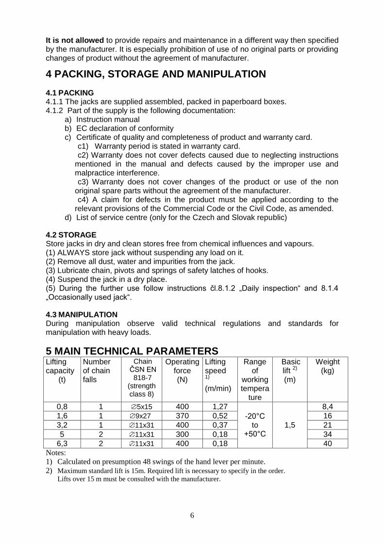
5 MAIN TECHNICAL PARAMETERS Lifting capacity
(t)
Number of chain falls
Chain ČSN EN 818-7
(strength class 8)
Operating force (N)
Lifting speed 1) (m/min)
Range of
working tempera
ture
Basic lift 2) (m)
Weight (kg)
0,8 1 5x15 400 1,27
-20°C to
+50°C 1,5
8,4
1,6 1 9x27 370 0,52 16
3,2 1 11x31 400 0,37 21
5 2 11x31 300 0,18 34
6,3 2 11x31 400 0,18 40 Notes:
1) Calculated on presumption 48 swings of the hand lever per minute.
2) Maximum standard lift is 15m. Required lift is necessary to specify in the order. Lifts over 15 m must be consulted with the manufacturer.

7
5.1 MECHANICAL CLASSIFICATION Safety and life of jack is guaranteed under presumption it works in accordance with the specified classification. Jack is designed for class 1Bm according to the regulation FEM 9.511 – see diagram 5.1. (corresponds to the classification of the mechanism M3 according to the ISO 4301/1). Average daily working time is set by the loading diagram.
Diagram 5.1 MECHANICAL CLASSIFICATION
Load diagram (Load distribution)
Definitions Cubic mean value
Average daily operating time (h)
1
(light)
Mechanisms or parts thereof,
usually subject to very small
loads and in exceptional cases
only to maximum loads.
k 0,50
1 - 2
2
(medium)
Mechanisms or parts thereof,
usually subject to small loads
but rather often to maximum
loads.
0,50< k 0,63
0,5 - 1
3
(heavy)
Mechanisms or parts thereof,
usually subject to medium
loads but frequently to
maximum loads.
0,63< k 0,80
0,25 – 0,5
4
(very heavy)
Mechanisms or parts thereof,
usually subject to maximum
or almost maximum loads.
0,80< k 1,00
0,12 – 0,25
Load diagram Load diagram Load diagram Load diagram 1 2 3 4
% operating time
5.2 MATERIAL AND VERSION
5.2.1 All parts of the jack are made of steel and cast iron, brake inserts of brass or metal-ceramic material.
5.2.2. Materials susceptible to the creation of an incentive spar in accordance with of the annex no.2 article 1.3.1 to the ministerial order no.23/2003 collection of laws and harmonized technical standards ČSN EN 1127-2 article 6.4.4, ČSN EN 1127-1 čl.6.4.4 and ČSN EN 13 463-1 article 8.1. are not used.
5.2.3. Materials with dangerous effects of static electricity in accordance with ČSN EN 1127-2 article 6.4.7, ČSN EN 1127-1 article 6.4.7, ČSN EN 13463-1 article 7.4.3 and ČSN 33 2030 are not used in the jack.
5.2.4 The jack does not exceed the noise value specified in the annex no.1 article 1.7.4.2 letter u NV 176/2008 collection of laws (directive EP and RE no.2006/42/EC).

8
Note: Articles 5.2.2 and 5.2.3 apply for configuration of jack to the environment with explosion risk.
5.3 DATA ON THE PRODUCT
Every single product is fitted with the label, where the following data are stated:
Standard version: Version for environment with explosion risk:
manufacturer designation manufacturer designation
address of manufacturer address of manufacturer
type of product type of product
lifting capacity lifting capacity
serial number serial number
year of production year of production
CE marking CE marking
sign of protection type (IM2c for group I , II2GDcT6for group II)
6 INSTALLATION OF JACK Prior to installing and usage of the jack, inspect it carefully for possible damages. 6.1 CHECKING BEFORE THE INSTALLATION 6.1.1 Load-carrying structure
! WARNING ALWAYS make sure the load-carrying structure is firm enough to support the weight
of load and jack. The installation must not be provided onto the structure, where the load-carrying capacity cannot be checked.
ALWAYS the user is responsible for the load-carrying structure! 6.2 SUSPENSION OF JACK
! CAUTION
Be careful during suspending a jack on the pendant element and ensure appropriate conditions for suspending according to the environment character (working platform, auxiliary lifting device, etc.), to avoid endanger or injury of people. Use safety equipment when suspending jack in heights to avoid a fall from height. The user is responsible for creating conditions and providing the installation of the jack. 6.2.1 Lubrication of chain Put the thin layer of oil on chain preferably by the help of spray. Regular lubrication will avoid wear and corrosion of chain and lengthen its life. 6.2.2 Checking the chain position Check, whether the lower block is not turned over (two fall jack 5t and 6,3t) and chain twisted as on picture 6.2a and 6.2b. If the chain is twisted, return it to its origin position. NEVER suspend a load on twisted chain. The chain is not twisted if the welded parts of all links are in one row.

9
6.3 SETTING THE LENGTH OF CHAIN WE USUALLY NEED TO SET THE LENTGH OF CHAIN (SPAN OF HOOKS) TO REQUIRED DISTANCE FOR SUSPENDING HOOKS BEFORE LIFTING OR PULLING. Set the selector lever (1) on hand lever (2) to the neutral position – see fig. 6.3. At this position of the selector lever we can rotate with the hand wheel (4) and move with chain in both directions. During moving the chain straight the chain in such a way to avoid its jamming or accumulation at the body of the jack. 6.4 POSITION OF THE JACK DURING PULLING The jack must be installed in such a way, the axes of hooks and chain under load were in one straight line without twisted chain.
THE CHAIN SHALL BE STRAIGHTEN UP IN SUCH A WAY THE LUGS AFTER WELDING WERE ON ONE SIDE
Fig. 6.2a Chain twisting
BY TURNING OVER OF THE BLOCK THE CHAIN GETS TWISTED BY TURNING THE BLOCK BACK THE CHAIN GETS STRAIGHTEN
Fig. 6.2b Turning over of the block
Neutral position
Lifting position
Lowering position
fig.6.3 Setting the length of chain
Position of the jack
Hanging element
Sling
Hook hanging

10
6.5 LIFTING (PULLING) OR LOWERING Before lifting pull out the selector lever and set it to mark lifting – arrow up (see fig. 6.3). Provide lifting by the pendulous motion of the hand lever. On the beginning of lifting prior to tensioning of the chain, hold the hand wheel so as not to be taken along by lever during its reverse motion. Prior to lowering of a load or releasing tensioned chain move the selector lever to the position on mark lowering – arrow down (see fig. 6.3). By pendulous motion of the hand lever lower the load or release the tensioned chain. During any change of position of the selector lever make sure the selector lever properly fit into the bed in the hand lever. The first motion of hand lever after the change of chain motion (after moving of selector lever) is slightly blocked. This situation happen due stronger tightening of the brake, especially when heavier loads are manipulated. In this case release brake by the energetic motion of hand lever and at the same time unblock hand lever. 6.6 SAFETY OF JACK – INSTRUCTIONS FOR OPERATOR Lifting and lowering can be interrupted in any height of lift. The stability of the load position is ensured by the lamella brake. The jack is ensured against overloading by the shear pin (A) in the hand lever. When shearing the shear pin the position of a load remains stabilised. With sheared pin the load can be safely lowered only. Two spare shear pins (B) are placed in openings of the hand lever (see fig. 6.3). From the safety reasons it is not allowed to use other than origin shear pins. 6.7 CHECKING BEFORE USE
! CAUTION (1) Firstly look again to the previous articles of this manual and make sure all steps
were correctly done and all parts are safely assembled. (2) Check, whether hooks are correctly suspended and safety latches are snapped. (3) Check visually load carrying construction or the suspending elements, whether
they are without defects. (4) By several motions of hand lever check the function without a load. (5) Provide several lifting and lowering with a suitable load (10% to 50% of lifting
capacity). At the same time check the brake, whether during lowering and stopping is the load kept without slipping.
7 OPERATION 7.1 USE OF THE JACK The jack is multiuse device, determined for lifting, lowering and pulling of loads at a workplace. Can be used not only in standard environment but also in environment with explosion risk, if the label is marked with symbol of protection type – see articlel.2.3, 2.4 and 5.3 of this manual. It is operated solely by the help of hand lever. It is determined for organisation as well as for private persons. Since dealing with heavy loads may involve unexpected danger, all the “Safety instructions” according to the chapter 3 must be followed.
! WARNING Do not continue to operate if the chain stopper (anchor) or lower block (at two fall types) contacts the jack’s body. Damage of the chain stopper (or lower block) can lead to the fall of the load. During pulling or tensioning sudden movement of the load

11
can happen and thus release and fall of the unsupported jack. Take therefore a special care.
! WARNING In exceptional cases, when using jacks with a long lift (15m and more) dangerous heating of the brake during lowering of loads can occurs (uninterrupted and quick lowering). In this cases it is necessary to lower the load slowly with interruptions.
! WARNING NEVER suspend a load on jack without prior active pre-lifting of a load by the jack. A fall of a load could happen due to insufficiently tight brake.
! CAUTION When lifting loads that are to be suspended over to another lifting device (crane, fork lift, etc.) it is necessary to unload the load chain (chains) by hand lever of the jack, not lifting the load by another lifting device. Only the above mentioned procedure ensure problems free releasing of the jack’s brake after removing a load. 7.2 SAFETY WORKING ENVIRONMENT
! WARNING (1) The operator must be provably familiar with this manual, keep valid safety and
hygienic regulations and must be authorised to operate this device. (2) Operator must be equipped with helmet, gloves and protective shoes. (3) Only verified binding means of appropriate lifting capacity is to be used for binding
loads. (4) When more persons take part in the operation, always one responsible person,
familiar with safety instructions, must be determined for manipulation with the jack.
(5) The operator must have a clear and unobstructed view of the working area before starting the work. If this is not possible, a second or more persons must serve in the nearby area.
(6) The operator must check the entire work place is safe and whether the is a possibility of escaping in case of endanger before operating the jack.
(7) During works with the jack a sufficient distance between operator and load must be kept. It is prohibited to lift or lower bulky loads that makes impossible to keep sufficient distance.
(8) When operating the jack in limited areas, you must prevent the hook or load contact into any obstacle or to the body of the jack.

12
8 INSPECTION OF JACK 8.1 INSPECTION 8.1.1 Inspection classification (1) Initial inspection: prior to initial use. All new or repaired jacks shall be inspected by designated qualified person to ensure compliance with the applicable provisions of this manual. (2) Inspection procedure for jacks in regular service is divided into two general classifications based on the intervals of inspections. Intervals of inspections depend on the condition of the critical components and the degree of their wear deterioration or malfunction. The respective intervals are defined in the following way: (a) Daily inspection: visual examination provided by the operator designated by the user on the beginning of each usage. (b) Regular inspection: visual inspection provided by the operator designated by the user. 1) normal service – annually, 2) heavy service – semi annually, 3) special or infrequent service – according to the recommendation of the competent person at first usage and according to the directions of the qualified service personnel (maintenance worker). 8.1.2 Daily inspection Items such as those recommended in paragraph 8.2(1) „Daily inspection“ should be inspected for damages and defects. Provide this inspection also during operation in the interval between regular inspections. A designated personnel shall determine, whether any defects or damages constitute a hazard or will require more detailed inspection. 8.1.3 Regular inspection Complete inspections of jacks shall be performed as recommended regular inspections. During these inspections the jack can stay on its usual place and dismantling is not necessary. Recommended regular inspection stated in paragraph 8.2(2) must be provided under supervision of the designated personnel to determine whether the disassembly is necessary. These inspections shall include the requirements of daily inspection. 8.1.4 Occasionally used jack (1) A jack which has been idle for a period of one month or more but less than one year before returning to service shall be given an inspection conforming to the requirements of paragraph 8.1.2. (2) A jack which has been idle for a period of one year shall be given an inspection conforming to the requirements of paragraph 8.1.3 before it is placed in service. 8.1.5 Inspection record Always keep records about the performed checks, repairs, inspections and maintenance of jacks. Dated records should be maintained in time intervals specified in paragraph 8.1.1 (2)(b) and keep them on place determined by the user.

13
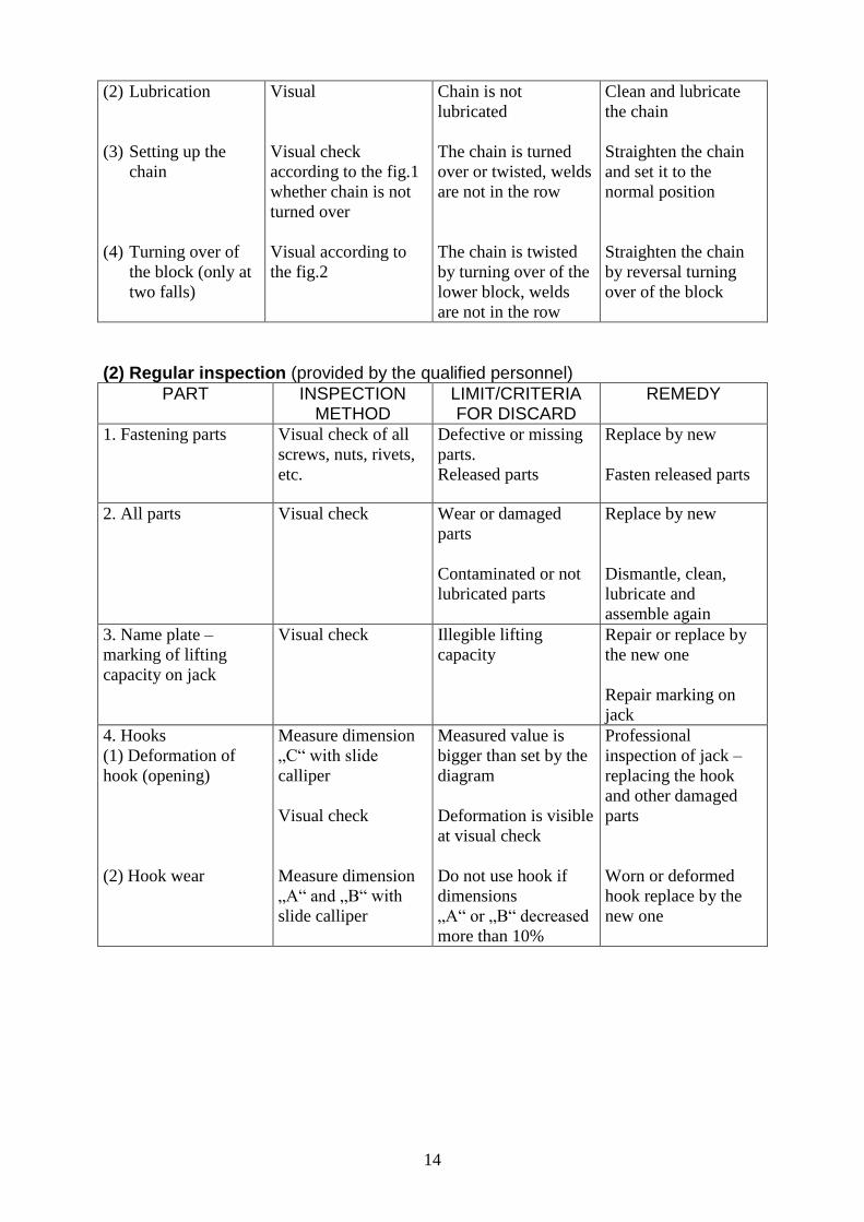
Defects found by the inspection or recorded during work must be announced to the person responsible for safety and determined by the user. 8.2 INSPECTION PROCEDURE (1) Daily inspection (provided by the operator or responsible person)
PART INSPECTION METHOD
LIMIT/CRITERIA FOR DISCARD
REMEDY
1. Function of jack Visual, hearing Chain binds, jumps,
make an excessive
noise, etc..
Clean and lubricate
the chain, if the
defects is not
removed replace the
chain
2. Fastening parts. Visual check of all
screws, nuts, rivets
etc.
Defective or missing
parts.
Unfasten parts
Replace by new one.
Fasten released parts
3. Hooks
(1) Appearance
(2) Hook rotating
(3) Safety latch
Visual
Turn the hook around
its axes.
By hand spring of
latch
Safety latch jump out
of the top of hook,
bind shank, other
visible deformation of
hook.
Hook does not rotate
fluently or jammed
Safety latch does not
return after pushing.
Professional
inspection of lifting
device – replacing of
hook and other
damaged parts
Clean up and
lubricate.
Clean, lubricate,
repair or replace
4. Load chain
(1) Appearance
Check visually the
whole chain
Cracks in the place of
welding, transversal
notches, deformation,
wear, rust
Replacement of the
chain
Note:
The complete wear of chain
cannot be determined by the
visual inspection. When
showing full wear, check the
chain according to the
„Regular inspection“
Wear in this part
Welding part Diameter
14
(2) Lubrication
(3) Setting up the
chain
(4) Turning over of
the block (only at
two falls)
Visual
Visual check
according to the fig.1
whether chain is not
turned over
Visual according to
the fig.2
Chain is not
lubricated
The chain is turned
over or twisted, welds
are not in the row
The chain is twisted
by turning over of the
lower block, welds
are not in the row
Clean and lubricate
the chain
Straighten the chain
and set it to the
normal position
Straighten the chain
by reversal turning
over of the block
(2) Regular inspection (provided by the qualified personnel)
PART INSPECTION METHOD
LIMIT/CRITERIA FOR DISCARD
REMEDY
1. Fastening parts
Visual check of all
screws, nuts, rivets,
etc.
Defective or missing
parts.
Released parts
Replace by new
Fasten released parts
2. All parts Visual check Wear or damaged
parts
Contaminated or not
lubricated parts
Replace by new
Dismantle, clean,
lubricate and
assemble again
3. Name plate –
marking of lifting
capacity on jack
Visual check Illegible lifting
capacity
Repair or replace by
the new one
Repair marking on
jack
4. Hooks
(1) Deformation of
hook (opening)
(2) Hook wear
Measure dimension
„C“ with slide
calliper
Visual check
Measure dimension
„A“ and „B“ with
slide calliper
Measured value is
bigger than set by the
diagram
Deformation is visible
at visual check
Do not use hook if
dimensions
„A“ or „B“ decreased
more than 10%
Professional
inspection of jack –
replacing the hook
and other damaged
parts
Worn or deformed
hook replace by the
new one

15
5. Chain
- elongation
Measuring of pitch
with slide calliper,
measure in place that
is most frequently in
contact with pulley
and nut
Dimension „p“ must
not exceed limit
values shown in the
following diagram
If limit values exceed,
ask for replacing the
chain
6. Brake
- function
Suspend a load equal to
nominal lifting capacity,
lift it at min. about 250
mm and lower it
After interruption of
operation, the brake
must keep the load in
any position of lifting
or lowering
If this does not
happened, ask for
repairing and
adjusting the brake
7. End stop
(anchor) of chain
Visual check End stop is not fasten
enough to the chain
Fasten the fitting
screw, Repair and
replace the damaged
connection
8. Ratchet pawl -
function
Visual check during
lifting
Ratchet pawl does not
jump behind the teeth
of ratchet wheel
Clean, lubricate or
replace the spring
p p p p p

16
9. Rotation of
block (at lifting
capacity 5t)
Rotate with block by
pulling the chain
Block does not rotate
fluently
Clean, lubricate or
repair
9 TROUBLE SHOOTING
Situation Cause Remedy
1. Jack does not keep up the
load.
Brake slips. Setting the brake or repair
according to the chapter
„Maintenance“.
2. Jack lift hard or does not
lift a load.
(1) Jack is overloaded.
(2) Damaged gear
transmission.
(1) Reduce weight of load to
nominal lifting capacity.
(2) Check parts according to
the chapter „Maintenance“.
3. Chain runs improperly, it is
jamming.
Damaged or worn out chain.
Check the chain or parts
according to: „Regular
inspection“ or provide repair
according to chapter
„Maintenance“.
4. Jack emits a special sound. (1) Insufficiently lubricated
chain.
(2) Insufficiently lubricated
gear transmission.
(1) Lubricate the chain.
(2) Lubricate gear
transmission with the grease.
5. Characteristic sound is not
heard when snapping the pawl
into the tooth of ratchet
wheel.
Loss of pawl function.
Rust, impurities, broken
spring.
Clean, replace the spring.
6. Safety latch of hook does
not work.
(1) Damaged safety latch.
(2) Deformed hook.
(1) Repair safety latch.
(2) Check the hook – see
„Daily inspection“.
10 LUBRICATION 10.1 GENERALLY Prior to application of the new lubricant, remove the old one, clean parts with a solvent degreaser and apply the new lubricant. Use the grease specified by the manufacturer.

17
10.2 GEARINGS Remove the cover on the opposite side of the hand lever. Remove the old lubricant and substitute by the new one. Use the grease PM – A2 or its equivalent. 10.3 CHAIN
! CAUTION The wrong maintenance and insufficient lubrication of the chain can cause a serious accident. ALWAYS lubricate the chain 1 x per week or often according to the demand of service. ALWAYS lubricate more often in a corrosive environment (seat water, sea climate,
acids, etc.) than in ordinary circumstances.
11 MAINTENANCE 11.1 SAFETY PRINCIPLES
! WARNING With exception of the exchange of the chain, only qualified personnel (service organisations) trained in safety and maintenance of these jacks can carry on maintenance, professional inspections and test. ALWAYS use only parts supplied by the manufacture. It is not permitted to carry on repairs and maintenance in other way than specified by the manufacturer. It means particularly forbiddance of using unoriginal spare parts or providing changes on the product without the approval of the manufacturer. ALWAYS check the function of the jack after carrying on the maintenance. ALWAYS mark damaged or repaired jack with a suitable safety sign (for example:
„OUT OF WORK“). NEVER do maintenance when a load is suspended on the jack. NEVER work with the jack that is under repair! 11.2 EXCHANGE OF THE LOAD CHAIN 11.2.1 SINGLE FALL CHAIN Unscrew the screw and remove the end stop (anchor) of the chain. Hook C link see fig.11.2 behind the last link of the free end of chain. Provide lowering until the end of the chain is slipped out enough. Fasten the end stop by the screw again to the last link of the free end of chain. Fasten the coupling with the hook on the other end of the chain. Check, whether the chain is not twisted.
NUT
IDLE BRANCH
LAST LINK OF THE OLD
CHAIN
LOADED BRANCH
LAST LINK OF THE NEW
CHAIN
C - LINK
Fig. 11.2 – Exchange of the load chain

18
11.2.2 TWO FALL CHAIN Unscrew the screw and remove the end stop (anchor) of the chain. Hook C link see fig.11.2 behind the last link of the free end of chain. Provide lowering until the end of chain is slipped out enough. Fasten the end stop to the last link of the free end of chain. Pull the end of chain through the pulley in the block and put to the yoke pin and secure by the cotter pin. 11.3 BRAKE ASSEMBLY Bind (unlock) the bend of the lock washer (2) and unscrew the nut (1). Remove gradually lock washer (2), stop (3), hand wheel (4), carrier wheel (5) and hand lever (11). Unscrew cover (6) and remove braking inserts (9a), ratchet wheel (7), braking inserts (9b) and inserts (10). After checking according to the article 11.6 provide assembly in the reverse way. After assembly it necessary to provide brake adjustment according to the article 11.4. 11.4 BRAKE ADJUSTMENT The stop (3) and dog on hand wheel ( 2A or 2B) limits the axial clearance in the brake. The angle between the stop and the dog is set by the manufacturer to 50°- see fig. If this angle exceeds value 50° during using of the jack, the brake must be readjust again. The adjustment should be done in the following way: Unscrew the nut (1), remove and turn the stop (3) in such a way to make the required angle with one of dogs (2A or 2B). If this cannot be reached, dismantle hand wheel (4) according to the procedure in article 11.3 and turn it in such a way so as after putting the stop (3) this make the required angle with one of the dogs (2A or 2B). Check the brake with a suitable load.
Fig. 11.3 – Brake assembly
6
8
7
4
5
1
2
3
11
9a
9b
10
Legend:
1- nut
2- lock washer
3- stop
4- hand wheel
5- carrier wheel
6- cover
7- ratchet wheel
8- ratchet pawl
9a,9b- braking inserts
10- washer
11- hand lever
1
2A
4
3
2B
Fig. 11.4 – Brake adjustment
19
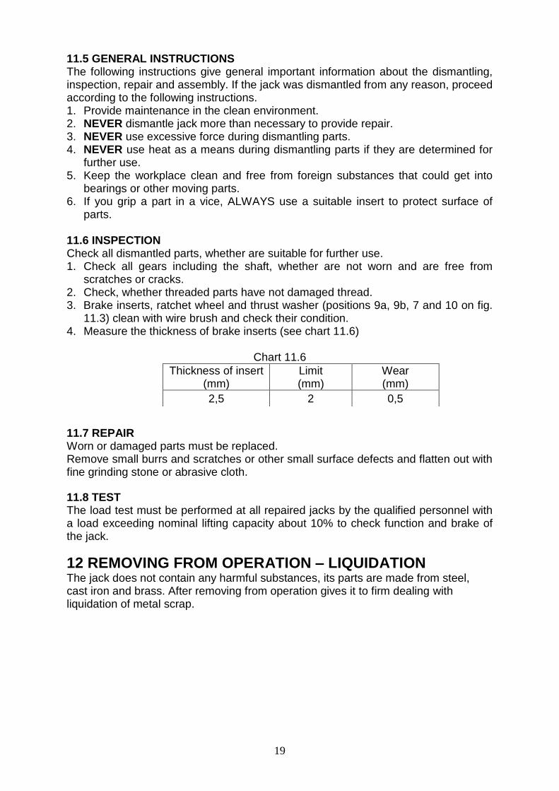
11.5 GENERAL INSTRUCTIONS The following instructions give general important information about the dismantling, inspection, repair and assembly. If the jack was dismantled from any reason, proceed according to the following instructions. 1. Provide maintenance in the clean environment. 2. NEVER dismantle jack more than necessary to provide repair. 3. NEVER use excessive force during dismantling parts. 4. NEVER use heat as a means during dismantling parts if they are determined for
further use. 5. Keep the workplace clean and free from foreign substances that could get into
bearings or other moving parts. 6. If you grip a part in a vice, ALWAYS use a suitable insert to protect surface of
parts. 11.6 INSPECTION Check all dismantled parts, whether are suitable for further use. 1. Check all gears including the shaft, whether are not worn and are free from
scratches or cracks. 2. Check, whether threaded parts have not damaged thread. 3. Brake inserts, ratchet wheel and thrust washer (positions 9a, 9b, 7 and 10 on fig.
11.3) clean with wire brush and check their condition. 4. Measure the thickness of brake inserts (see chart 11.6)
Chart 11.6 11.7 REPAIR Worn or damaged parts must be replaced. Remove small burrs and scratches or other small surface defects and flatten out with fine grinding stone or abrasive cloth. 11.8 TEST The load test must be performed at all repaired jacks by the qualified personnel with a load exceeding nominal lifting capacity about 10% to check function and brake of the jack.
12 REMOVING FROM OPERATION – LIQUIDATION The jack does not contain any harmful substances, its parts are made from steel, cast iron and brass. After removing from operation gives it to firm dealing with liquidation of metal scrap.
Thickness of insert (mm)
Limit (mm)
Wear (mm)
2,5 2 0,5

20
13 RELATED DOCUMENTATION
of Law as amended
13.1 EC declaration of conformity
13.2 The instruction manual was elaborated in accordance with the following technical regulations, technical standards and national regulations:
Ministerial order No.176/2008 of the Coll. of Law as amended (Directive of EP and Council 2006/42/EC)
Ministerial order No.23/2003 of the Coll. of Law as amended (Directive of EP and Council 94/9/EC)
ČSN EN ISO 12100
ČSN EN 13157+A1
ČSN EN 1127 – 2
ČSN EN 1127 - 1
ČSN EN 13463 – 1
Regulation of CBM (Czech Bureau of Mine) No.22/89 of the Collection of Law
ČSN 33 2030.
14 FINAL REQUIREMENTS OF THE MANUFACTURER TO A CUSTOMER Any changes of the product, eventually use of unoriginal spare parts can be realised only based on approval of the manufacturer. When not observing this condition the manufacturer does not guarantee safety of this product. In such a case the manufacturer warranty does not apply to the product.