Embed Size (px)
Citation preview
This article was downloaded by: [University of Guelph]On: 08 June 2012, At: 20:30Publisher: Taylor & FrancisInforma Ltd Registered in England and Wales Registered Number: 1072954 Registered office: MortimerHouse, 37-41 Mortimer Street, London W1T 3JH, UK
Journal of Nuclear Science and TechnologyPublication details, including instructions for authors and subscription information:http://www.tandfonline.com/loi/tnst20
Safety of Super LWR, (I) Safety System DesignYuki ISHIWATARI a , Yoshiaki OKA a , Seiichi KOSHIZUKA b , Akifumi YAMAJI b & Jie LIU ca Nuclear Professional School, School of Engineering, The University of Tokyo, 2-22,Shirane-Shirakata, Tokai-mura, Naka-gun, Ibaraki, 319-1188b Department of Quantum Engineering and System Science, School of Engineering, TheUniversity of Tokyo, 7-3-1 Hongo, Bunkyo-ku, Tokyo, 113-8656c Department of Nuclear Engineering and Management, School of Engineering, TheUniversity of Tokyo, 7-3-1 Hongo, Bunkyo-ku, Tokyo, 113-8656
Available online: 05 Jan 2012
To cite this article: Yuki ISHIWATARI, Yoshiaki OKA, Seiichi KOSHIZUKA, Akifumi YAMAJI & Jie LIU (2005): Safety of SuperLWR, (I) Safety System Design, Journal of Nuclear Science and Technology, 42:11, 927-934
To link to this article: http://dx.doi.org/10.1080/18811248.2005.9711044
PLEASE SCROLL DOWN FOR ARTICLE
Full terms and conditions of use: http://www.tandfonline.com/page/terms-and-conditions
This article may be used for research, teaching, and private study purposes. Any substantial or systematicreproduction, redistribution, reselling, loan, sub-licensing, systematic supply, or distribution in any form toanyone is expressly forbidden.
The publisher does not give any warranty express or implied or make any representation that the contentswill be complete or accurate or up to date. The accuracy of any instructions, formulae, and drug dosesshould be independently verified with primary sources. The publisher shall not be liable for any loss, actions,claims, proceedings, demand, or costs or damages whatsoever or howsoever caused arising directly orindirectly in connection with or arising out of the use of this material.
Safety of Super LWR, (I)Safety System Design
Yuki ISHIWATARI1;�, Yoshiaki OKA1, Seiichi KOSHIZUKA2,Akifumi YAMAJI2 and Jie LIU3
1Nuclear Professional School, School of Engineering, The University of Tokyo,2-22, Shirane-Shirakata, Tokai-mura, Naka-gun, Ibaraki 319-1188
2Department of Quantum Engineering and System Science, School of Engineering, The University of Tokyo,7-3-1 Hongo, Bunkyo-ku, Tokyo 113-8656
3Department of Nuclear Engineering and Management, School of Engineering, The University of Tokyo,7-3-1 Hongo, Bunkyo-ku, Tokyo 113-8656
(Received April 25, 2005 and accepted in revised form September 8, 2005)
This paper describes design concept of safety system of the high-temperature supercritical pressure light watercooled reactor with downward-flow water rods (Super LWR). Since this reactor is once-through cooling system with-out water level and coolant circulation, the fundamental safety requirement is keeping core coolant flow rate while thatof light water reactors (LWR) is keeping coolant inventory. ‘‘Coolant supply from cold-leg’’ and ‘‘coolant outlet at hot-leg’’ are needed for it. The advantage of the once-through cooling system is that reactor depressurization induces corecoolant flow and cools the core. The downward-flow water rod system enhances this effect because the top dome andthe water rods supply its water inventory to the core like an ‘‘in-vessel accumulator.’’ The safety system of the SuperLWR is designed referring to those of LWR in consideration of its characteristics and safety principle. ‘‘Coolantsupply’’ is kept by high-pressure auxiliary feedwater system and low-pressure core injection system. ‘‘Coolant outlet’’is kept by safety relief valves and automatic depressurization system. The Super LWR is equipped with two independ-ent shutdown systems: reactor scram system and standby liquid control system. The capacities and the actuationconditions determined in this study are to be used in safety analysis.
KEYWORDS: once-through cooling cycle, supercritical-pressure, downward-flow water rod, safety principle,safety system design
I. Introduction
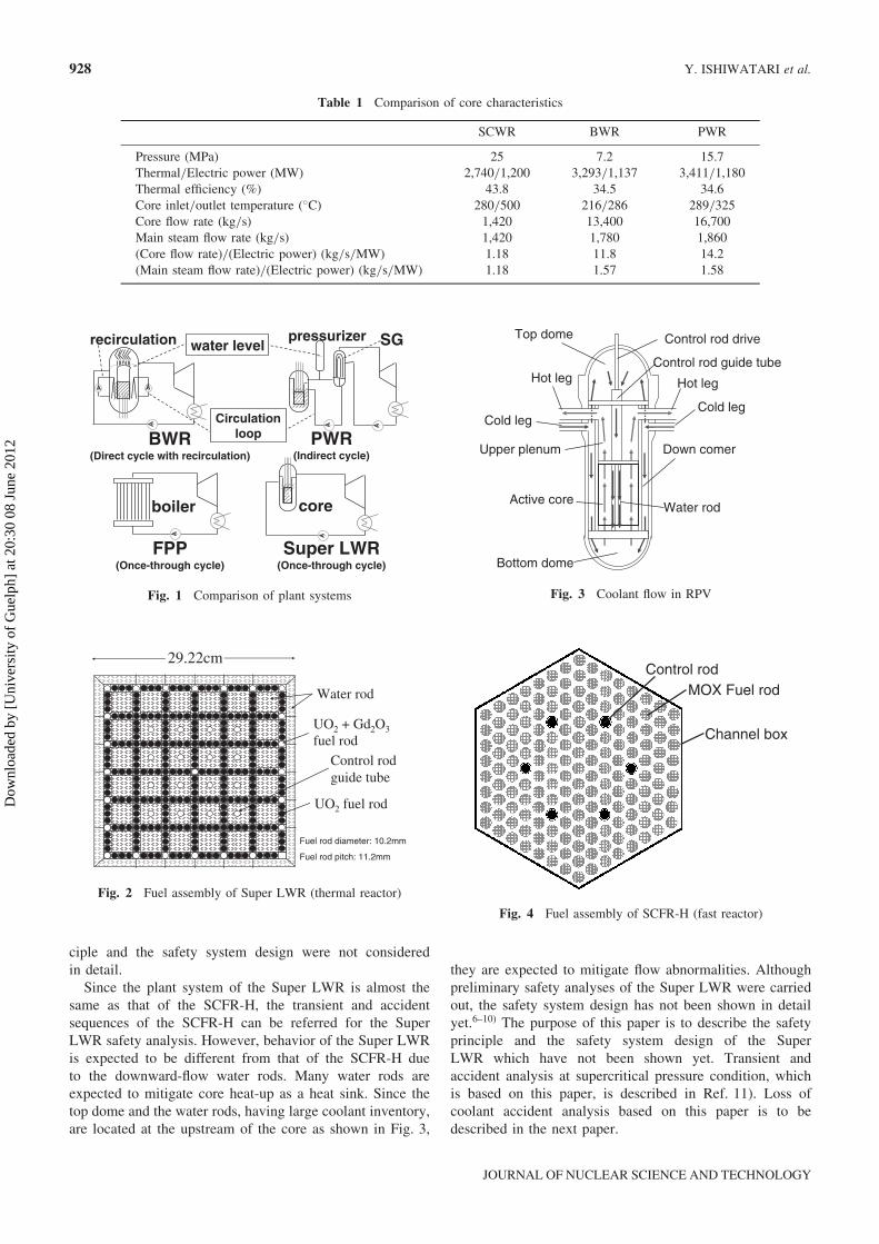
Design concept of supercritical pressure water cooledreactor (SCWR) has been studied by the University ofTokyo. Compared with light water reactors (LWR), the ad-vantages of the SCWR are simplicity of the reactor system,compactness of both the reactor and turbine system, and highthermal efficiency.1) The core characteristics of a typical de-sign of the SCWR are compared with those of boiling waterreactor (BWR) and pressurized water reactor (PWR) inTable 1.2) Boiling does not occur at supercritical pressure.The core coolant flow rate is much less than those ofLWR due to high enthalpy rise in the core and once-throughcycle without recirculation. The ratio of the core flow rate tothe electric power is about 1/10 of that of BWR and about1/12 of that of PWR.
The cooling system of the SCWR is compared with thoseof BWR, PWR and supercritical-pressure fossil-fired powerplant (FPP) in Fig. 1. The SCWR adopts once-through cool-ing system like FPP. The safety principle of the SCWRis different from that of LWR which has coolant circulationsystem and water level. Safety system design and safetyanalysis of the SCWR are required in consideration ofits characteristics.
The SCWR has the high-temperature thermal reactor
version (called Super LWR or SCLWR-H) and the high-tem-perature fast reactor version (called SCFR-H).2,3) The SuperLWR is mostly studied at the University of Tokyo at present.The cross section of the fuel assembly is shown in Fig. 2.Because the core flow rate of the Super LWR is much lowerthan those of LWR, narrow gap between the fuel rods istaken to keep coolant velocity high for heat removal.It is 1.0mm in the present design. The fuel assemblycontains many square water rods for neutron moderationbecause density of fuel channel coolant decreases substan-tially in upper part of the core. This arrangement is takento achieve uniform moderations due to uniform subchannelareas. Downward-flow water rod system is adopted toachieve higher coolant outlet temperature and to make axialdistribution of moderator density more uniform. The coolantflow in the reactor pressure vessel (RPV) is shown in Fig. 3.In the present design, 30% of the coolant supply is led tothe top dome and flows downward through the control rodguide tubes to the water rods. In the bottom dome it is mixedwith the coolant from the downcomer, and then flowsupward through the fuel channels.
In the past study, safety analysis of the SCFR-H wascarried out.4,5) The SCFR-H adopts the tight lattice hexago-nal fuel assembly without water rods as shown in Fig. 4.It was shown that flow abnormalities are the most importantincidents because ‘‘loss of feedwater flow’’ immediatelyleads to ‘‘loss of core coolant flow’’ in the once-throughcooling system. In the study of the SCFR-H, the safety prin-�Corresponding author, Tel. +81-29-287-8442, Fax. +81-29-287-
8438, E-mail: [email protected]
Journal of NUCLEAR SCIENCE and TECHNOLOGY, Vol. 42, No. 11, p. 927–934 (November 2005)
927
ORIGINAL PAPER
Dow
nloa
ded
by [
Uni
vers
ity o
f G
uelp
h] a
t 20:
30 0
8 Ju
ne 2
012
ciple and the safety system design were not consideredin detail.
Since the plant system of the Super LWR is almost thesame as that of the SCFR-H, the transient and accidentsequences of the SCFR-H can be referred for the SuperLWR safety analysis. However, behavior of the Super LWRis expected to be different from that of the SCFR-H dueto the downward-flow water rods. Many water rods areexpected to mitigate core heat-up as a heat sink. Since thetop dome and the water rods, having large coolant inventory,are located at the upstream of the core as shown in Fig. 3,
they are expected to mitigate flow abnormalities. Althoughpreliminary safety analyses of the Super LWR were carriedout, the safety system design has not been shown in detailyet.6–10) The purpose of this paper is to describe the safetyprinciple and the safety system design of the SuperLWR which have not been shown yet. Transient andaccident analysis at supercritical pressure condition, whichis based on this paper, is described in Ref. 11). Loss ofcoolant accident analysis based on this paper is to bedescribed in the next paper.
29.22cm
UO2 + Gd2O3
fuel rod
Water rod
UO2 fuel rod
Control rod guide tube
Fuel rod diameter: 10.2mm
Fuel rod pitch: 11.2mm
Fig. 2 Fuel assembly of Super LWR (thermal reactor)
Hot leg
Cold leg
Top dome
Water rodActive core
Control rod guide tube
Hot leg
Cold leg
Down comer
Bottom dome
Upper plenum
Control rod drive
Fig. 3 Coolant flow in RPV
Control rodMOX Fuel rod
Channel box
Fig. 4 Fuel assembly of SCFR-H (fast reactor)
Table 1 Comparison of core characteristics
SCWR BWR PWR
Pressure (MPa) 25 7.2 15.7Thermal/Electric power (MW) 2,740/1,200 3,293/1,137 3,411/1,180Thermal efficiency (%) 43.8 34.5 34.6Core inlet/outlet temperature (�C) 280/500 216/286 289/325Core flow rate (kg/s) 1,420 13,400 16,700Main steam flow rate (kg/s) 1,420 1,780 1,860(Core flow rate)/(Electric power) (kg/s/MW) 1.18 11.8 14.2(Main steam flow rate)/(Electric power) (kg/s/MW) 1.18 1.57 1.58
FPP(Once-through cycle)
Super LWR(Once-through cycle)
BWR(Direct cycle with recirculation)
PWR(Indirect cycle)
boiler
recirculation SG
core
pressurizerwater level
Circulation loop
Fig. 1 Comparison of plant systems
928 Y. ISHIWATARI et al.
JOURNAL OF NUCLEAR SCIENCE AND TECHNOLOGY
Dow
nloa
ded
by [
Uni
vers
ity o
f G
uelp
h] a
t 20:
30 0
8 Ju
ne 2
012
II. Safety Principle
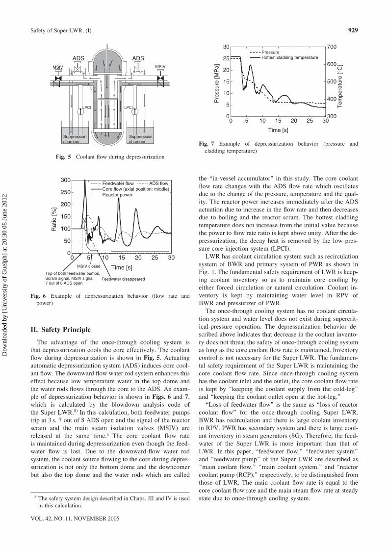
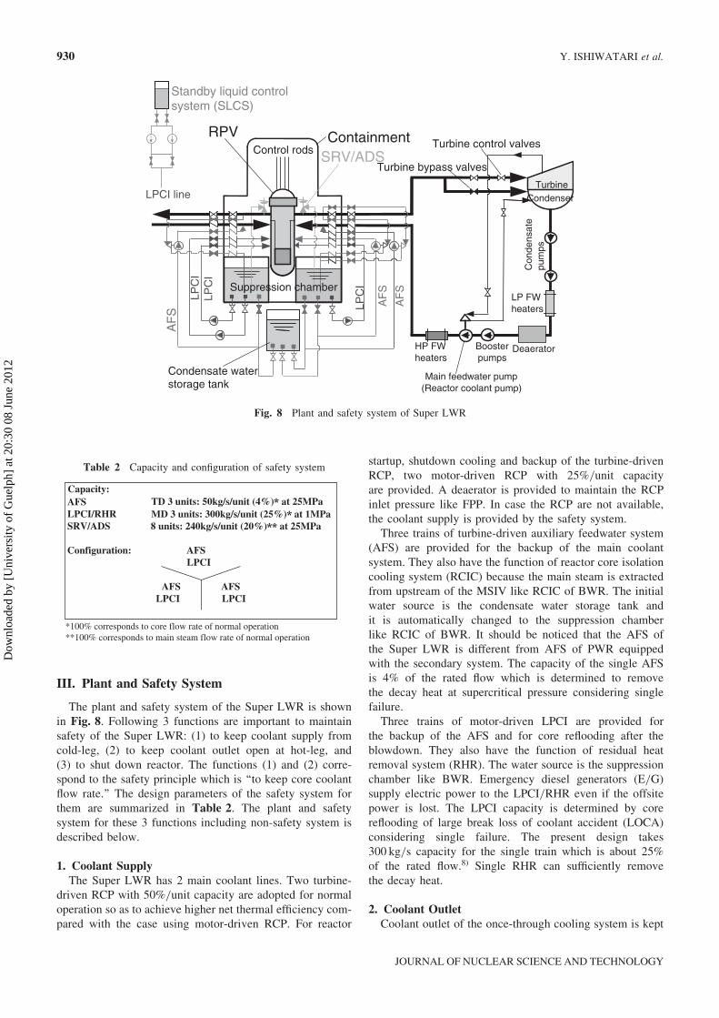
The advantage of the once-through cooling system isthat depressurization cools the core effectively. The coolantflow during depressurization is shown in Fig. 5. Actuatingautomatic depressurization system (ADS) induces core cool-ant flow. The downward flow water rod system enhances thiseffect because low temperature water in the top dome andthe water rods flows through the core to the ADS. An exam-ple of depressurization behavior is shown in Figs. 6 and 7,which is calculated by the blowdown analysis code ofthe Super LWR.8) In this calculation, both feedwater pumpstrip at 3 s. 7 out of 8 ADS open and the signal of the reactorscram and the main steam isolation valves (MSIV) arereleased at the same time.a The core coolant flow rateis maintained during depressurization even though the feed-water flow is lost. Due to the downward-flow water rodsystem, the coolant source flowing to the core during depres-surization is not only the bottom dome and the downcomerbut also the top dome and the water rods which are called
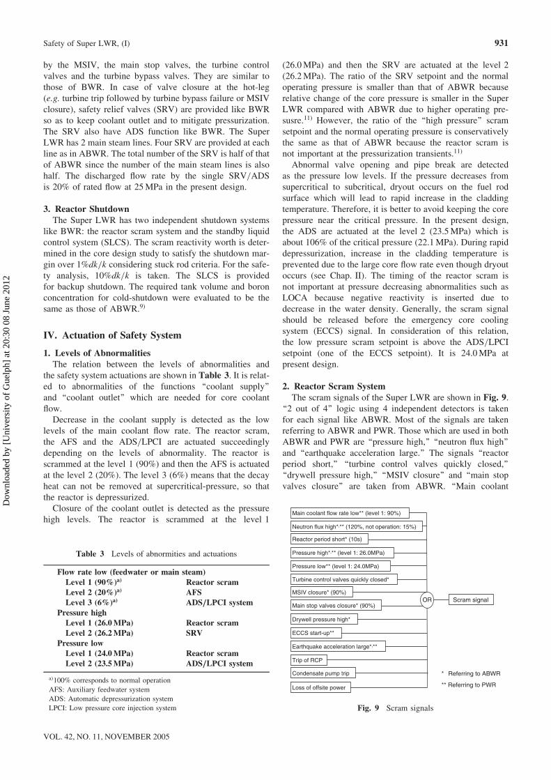
the ‘‘in-vessel accumulator’’ in this study. The core coolantflow rate changes with the ADS flow rate which oscillatesdue to the change of the pressure, temperature and the qual-ity. The reactor power increases immediately after the ADSactuation due to increase in the flow rate and then decreasesdue to boiling and the reactor scram. The hottest claddingtemperature does not increase from the initial value becausethe power to flow rate ratio is kept above unity. After the de-pressurization, the decay heat is removed by the low pres-sure core injection system (LPCI).
LWR has coolant circulation system such as recirculationsystem of BWR and primary system of PWR as shown inFig. 1. The fundamental safety requirement of LWR is keep-ing coolant inventory so as to maintain core cooling byeither forced circulation or natural circulation. Coolant in-ventory is kept by maintaining water level in RPV ofBWR and pressurizer of PWR.
The once-through cooling system has no coolant circula-tion system and water level does not exist during supercrit-ical-pressure operation. The depressurization behavior de-scribed above indicates that decrease in the coolant invento-ry does not threat the safety of once-through cooling systemas long as the core coolant flow rate is maintained. Inventorycontrol is not necessary for the Super LWR. The fundamen-tal safety requirement of the Super LWR is maintaining thecore coolant flow rate. Since once-through cooling systemhas the coolant inlet and the outlet, the core coolant flow rateis kept by ‘‘keeping the coolant supply from the cold-leg’’and ‘‘keeping the coolant outlet open at the hot-leg.’’
‘‘Loss of feedwater flow’’ is the same as ‘‘loss of reactorcoolant flow’’ for the once-through cooling Super LWR.BWR has recirculation and there is large coolant inventoryin RPV. PWR has secondary system and there is large cool-ant inventory in steam generators (SG). Therefore, the feed-water of the Super LWR is more important than that ofLWR. In this paper, ‘‘feedwater flow,’’ ‘‘feedwater system’’and ‘‘feedwater pump’’ of the Super LWR are described as‘‘main coolant flow,’’ ‘‘main coolant system,’’ and ‘‘reactorcoolant pump (RCP),’’ respectively, to be distinguished fromthose of LWR. The main coolant flow rate is equal to thecore coolant flow rate and the main steam flow rate at steadystate due to once-through cooling system.
0 5 10 15 20 25 300
50
100
150
200
250
300 Feedwater flow ADS flow Core flow (axial position: middle) Reactor power
Time [s]
Rat
io [%
]
MSIV closed
Trip of both feedwater pumps,Scram signal, MSIV signal,7 out of 8 ADS open
Feedwater disappeared
Fig. 6 Example of depressurization behavior (flow rate andpower)
0 5 10 15 20 25 300
5
10
15
20
25
30 Pressure
Time [s]
Pre
ssur
e [M
Pa]
300
400
500
600
700
Hottest cladding temperature
Tem
pera
ture
[°C
]
Fig. 7 Example of depressurization behavior (pressure andcladding temperature)
ADSADS
Suppression chamber
Suppression chamber
LPCI LPCI
MSIV MSIV
Fig. 5 Coolant flow during depressurization
a The safety system design described in Chaps. III and IV is usedin this calculation.
Safety of Super LWR, (I) 929
VOL. 42, NO. 11, NOVEMBER 2005
Dow
nloa
ded
by [
Uni
vers
ity o
f G
uelp
h] a
t 20:
30 0
8 Ju
ne 2
012
III. Plant and Safety System
The plant and safety system of the Super LWR is shownin Fig. 8. Following 3 functions are important to maintainsafety of the Super LWR: (1) to keep coolant supply fromcold-leg, (2) to keep coolant outlet open at hot-leg, and(3) to shut down reactor. The functions (1) and (2) corre-spond to the safety principle which is ‘‘to keep core coolantflow rate.’’ The design parameters of the safety system forthem are summarized in Table 2. The plant and safetysystem for these 3 functions including non-safety system isdescribed below.
1. Coolant SupplyThe Super LWR has 2 main coolant lines. Two turbine-
driven RCP with 50%/unit capacity are adopted for normaloperation so as to achieve higher net thermal efficiency com-pared with the case using motor-driven RCP. For reactor
startup, shutdown cooling and backup of the turbine-drivenRCP, two motor-driven RCP with 25%/unit capacityare provided. A deaerator is provided to maintain the RCPinlet pressure like FPP. In case the RCP are not available,the coolant supply is provided by the safety system.
Three trains of turbine-driven auxiliary feedwater system(AFS) are provided for the backup of the main coolantsystem. They also have the function of reactor core isolationcooling system (RCIC) because the main steam is extractedfrom upstream of the MSIV like RCIC of BWR. The initialwater source is the condensate water storage tank andit is automatically changed to the suppression chamberlike RCIC of BWR. It should be noticed that the AFS ofthe Super LWR is different from AFS of PWR equippedwith the secondary system. The capacity of the single AFSis 4% of the rated flow which is determined to removethe decay heat at supercritical pressure considering singlefailure.
Three trains of motor-driven LPCI are provided forthe backup of the AFS and for core reflooding after theblowdown. They also have the function of residual heatremoval system (RHR). The water source is the suppressionchamber like BWR. Emergency diesel generators (E/G)supply electric power to the LPCI/RHR even if the offsitepower is lost. The LPCI capacity is determined by corereflooding of large break loss of coolant accident (LOCA)considering single failure. The present design takes300 kg/s capacity for the single train which is about 25%of the rated flow.8) Single RHR can sufficiently removethe decay heat.
2. Coolant OutletCoolant outlet of the once-through cooling system is kept
LPCI line
Standby liquid control system (SLCS)
Control rods
RPV
Turbine bypass valves
Turbine control valves
Condenser
LP FW heaters
HP FW heaters
Main feedwater pump(Reactor coolant pump)
LPC
I
AF
S
Turbine
AF
S
AF
S
Condensate water storage tank
LPC
ILP
CI
Suppression chamber
SRV/ADSContainment
Deaerator
Con
dens
ate
pum
ps
Booster pumps
Fig. 8 Plant and safety system of Super LWR
Table 2 Capacity and configuration of safety system
AFSLPCI/RHRSRV/ADS
LPCI
AFS AFSLPCI LPCI
**100% corresponds to main steam flow rate of normal operation*100% corresponds to core flow rate of normal operation
Configuration: AFS
Capacity:
8 units: 240kg/s/unit (20%) at 25MPaMD 3 units: 300kg/s/unit (25%) at 1MPaTD 3 units: 50kg/s/unit (4%) at 25MPa
930 Y. ISHIWATARI et al.
JOURNAL OF NUCLEAR SCIENCE AND TECHNOLOGY
Dow
nloa
ded
by [
Uni
vers
ity o
f G
uelp
h] a
t 20:
30 0
8 Ju
ne 2
012
by the MSIV, the main stop valves, the turbine controlvalves and the turbine bypass valves. They are similar tothose of BWR. In case of valve closure at the hot-leg(e.g. turbine trip followed by turbine bypass failure or MSIVclosure), safety relief valves (SRV) are provided like BWRso as to keep coolant outlet and to mitigate pressurization.The SRV also have ADS function like BWR. The SuperLWR has 2 main steam lines. Four SRV are provided at eachline as in ABWR. The total number of the SRV is half of thatof ABWR since the number of the main steam lines is alsohalf. The discharged flow rate by the single SRV/ADSis 20% of rated flow at 25MPa in the present design.
3. Reactor ShutdownThe Super LWR has two independent shutdown systems
like BWR: the reactor scram system and the standby liquidcontrol system (SLCS). The scram reactivity worth is deter-mined in the core design study to satisfy the shutdown mar-gin over 1%dk=k considering stuck rod criteria. For the safe-ty analysis, 10%dk=k is taken. The SLCS is providedfor backup shutdown. The required tank volume and boronconcentration for cold-shutdown were evaluated to be thesame as those of ABWR.9)
IV. Actuation of Safety System
1. Levels of AbnormalitiesThe relation between the levels of abnormalities and
the safety system actuations are shown in Table 3. It is relat-ed to abnormalities of the functions ‘‘coolant supply’’and ‘‘coolant outlet’’ which are needed for core coolantflow.
Decrease in the coolant supply is detected as the lowlevels of the main coolant flow rate. The reactor scram,the AFS and the ADS/LPCI are actuated succeedinglydepending on the levels of abnormality. The reactor isscrammed at the level 1 (90%) and then the AFS is actuatedat the level 2 (20%). The level 3 (6%) means that the decayheat can not be removed at supercritical-pressure, so thatthe reactor is depressurized.
Closure of the coolant outlet is detected as the pressurehigh levels. The reactor is scrammed at the level 1
(26.0MPa) and then the SRV are actuated at the level 2(26.2MPa). The ratio of the SRV setpoint and the normaloperating pressure is smaller than that of ABWR becauserelative change of the core pressure is smaller in the SuperLWR compared with ABWR due to higher operating pre-susre.11) However, the ratio of the ‘‘high pressure’’ scramsetpoint and the normal operating pressure is conservativelythe same as that of ABWR because the reactor scram isnot important at the pressurization transients.11)
Abnormal valve opening and pipe break are detectedas the pressure low levels. If the pressure decreases fromsupercritical to subcritical, dryout occurs on the fuel rodsurface which will lead to rapid increase in the claddingtemperature. Therefore, it is better to avoid keeping the corepressure near the critical pressure. In the present design,the ADS are actuated at the level 2 (23.5MPa) which isabout 106% of the critical pressure (22.1MPa). During rapiddepressurization, increase in the cladding temperature isprevented due to the large core flow rate even though dryoutoccurs (see Chap. II). The timing of the reactor scram isnot important at pressure decreasing abnormalities such asLOCA because negative reactivity is inserted due todecrease in the water density. Generally, the scram signalshould be released before the emergency core coolingsystem (ECCS) signal. In consideration of this relation,the low pressure scram setpoint is above the ADS/LPCIsetpoint (one of the ECCS setpoint). It is 24.0MPa atpresent design.
2. Reactor Scram SystemThe scram signals of the Super LWR are shown in Fig. 9.
‘‘2 out of 4’’ logic using 4 independent detectors is takenfor each signal like ABWR. Most of the signals are takenreferring to ABWR and PWR. Those which are used in bothABWR and PWR are ‘‘pressure high,’’ ‘‘neutron flux high’’and ‘‘earthquake acceleration large.’’ The signals ‘‘reactorperiod short,’’ ‘‘turbine control valves quickly closed,’’‘‘drywell pressure high,’’ ‘‘MSIV closure’’ and ‘‘main stopvalves closure’’ are taken from ABWR. ‘‘Main coolant
Table 3 Levels of abnormities and actuations
Flow rate low (feedwater or main steam)Level 1 (90%)aÞ Reactor scramLevel 2 (20%)aÞ AFSLevel 3 (6%)aÞ ADS/LPCI system
Pressure highLevel 1 (26.0MPa) Reactor scramLevel 2 (26.2MPa) SRV
Pressure lowLevel 1 (24.0MPa) Reactor scramLevel 2 (23.5MPa) ADS/LPCI system
aÞ100% corresponds to normal operation
AFS: Auxiliary feedwater system
ADS: Automatic depressurization system
LPCI: Low pressure core injection system
OR Scram signal
Trip of RCP
Main coolant flow rate low** (level 1: 90%)
Pressure high*,** (level 1: 26.0MPa)
Loss of offsite power
Neutron flux high*,** (120%, not operation: 15%)
Turbine control valves quickly closed*
Pressure low** (level 1: 24.0MPa)
Reactor period short* (10s)
Drywell pressure high*
ECCS start-up**
MSIV closure* (90%)
Condensate pump trip
Main stop valves closure* (90%)
Earthquake acceleration large*,**
* Referring to ABWR
** Referring to PWR
Fig. 9 Scram signals
Safety of Super LWR, (I) 931
VOL. 42, NO. 11, NOVEMBER 2005
Dow
nloa
ded
by [
Uni
vers
ity o
f G
uelp
h] a
t 20:
30 0
8 Ju
ne 2
012
flow rate lowb,’’ ‘‘pressure low’’ and ‘‘ECCS start-up’’ aretaken from PWR.
Since the main coolant flow rate is important for the once-through cooling system, ‘‘trip of RCP’’ itself is added tothe scram signals. Detection of the RCP trip is supposed tobe similar to that of ‘‘low RCP shaft speed’’ of PWR. Sinceloss of coolant supply from the condensers to the deaeratorwill lead to RCP trip with time delay due to RCP inlet pres-sure low, ‘‘condensate pump trip’’ is added to the scramsignals so that the reactor power decreases before the RCPtrip. When the offsite power is lost, scram signal is releasedby ‘‘turbine control valves quickly closed’’ due to turbinetrip or ‘‘condensate pump trip.’’ In the present design, ‘‘lossof offsite power’’ itself is added to the scram signals, sothat 3 types of scram signals are expected at ‘‘loss of offsitepower’’ transient.
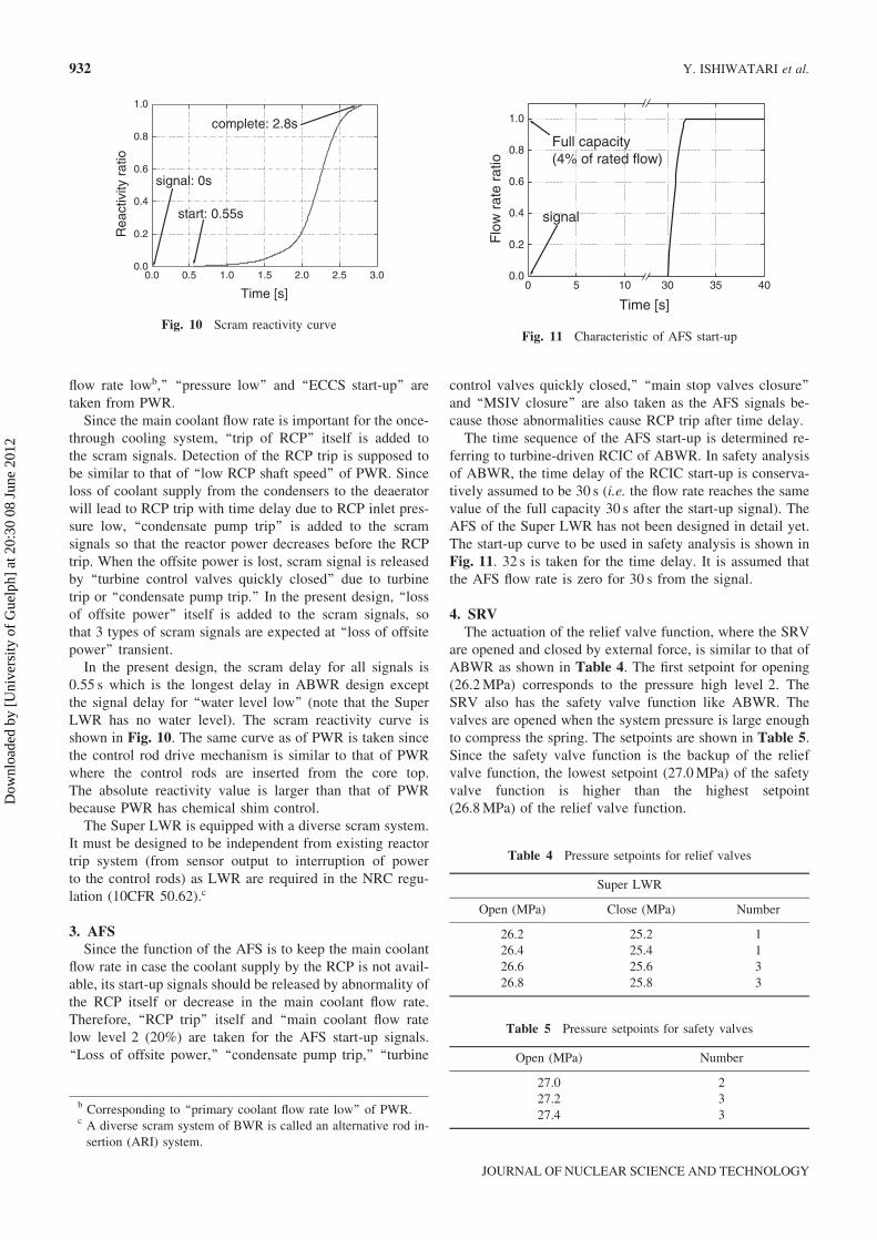
In the present design, the scram delay for all signals is0.55 s which is the longest delay in ABWR design exceptthe signal delay for ‘‘water level low’’ (note that the SuperLWR has no water level). The scram reactivity curve isshown in Fig. 10. The same curve as of PWR is taken sincethe control rod drive mechanism is similar to that of PWRwhere the control rods are inserted from the core top.The absolute reactivity value is larger than that of PWRbecause PWR has chemical shim control.
The Super LWR is equipped with a diverse scram system.It must be designed to be independent from existing reactortrip system (from sensor output to interruption of powerto the control rods) as LWR are required in the NRC regu-lation (10CFR 50.62).c
3. AFSSince the function of the AFS is to keep the main coolant
flow rate in case the coolant supply by the RCP is not avail-able, its start-up signals should be released by abnormality ofthe RCP itself or decrease in the main coolant flow rate.Therefore, ‘‘RCP trip’’ itself and ‘‘main coolant flow ratelow level 2 (20%) are taken for the AFS start-up signals.‘‘Loss of offsite power,’’ ‘‘condensate pump trip,’’ ‘‘turbine
control valves quickly closed,’’ ‘‘main stop valves closure’’and ‘‘MSIV closure’’ are also taken as the AFS signals be-cause those abnormalities cause RCP trip after time delay.
The time sequence of the AFS start-up is determined re-ferring to turbine-driven RCIC of ABWR. In safety analysisof ABWR, the time delay of the RCIC start-up is conserva-tively assumed to be 30 s (i.e. the flow rate reaches the samevalue of the full capacity 30 s after the start-up signal). TheAFS of the Super LWR has not been designed in detail yet.The start-up curve to be used in safety analysis is shown inFig. 11. 32 s is taken for the time delay. It is assumed thatthe AFS flow rate is zero for 30 s from the signal.
4. SRVThe actuation of the relief valve function, where the SRV
are opened and closed by external force, is similar to that ofABWR as shown in Table 4. The first setpoint for opening(26.2MPa) corresponds to the pressure high level 2. TheSRV also has the safety valve function like ABWR. Thevalves are opened when the system pressure is large enoughto compress the spring. The setpoints are shown in Table 5.Since the safety valve function is the backup of the reliefvalve function, the lowest setpoint (27.0MPa) of the safetyvalve function is higher than the highest setpoint(26.8MPa) of the relief valve function.
0.0 0.5 1.0 1.5 2.0 2.5 3.00.0
0.2
0.4
0.6
0.8
1.0
complete: 2.8s
start: 0.55s
signal: 0s
Rea
ctiv
ity r
atio
Time [s]
Fig. 10 Scram reactivity curve
0 5 10 30 35 400.0
0.2
0.4
0.6
0.8
1.0
Full capacity(4% of rated flow)
signal
Flo
w r
ate
ratio
Time [s]
Fig. 11 Characteristic of AFS start-up
Table 4 Pressure setpoints for relief valves
Super LWR
Open (MPa) Close (MPa) Number
26.2 25.2 126.4 25.4 126.6 25.6 326.8 25.8 3
Table 5 Pressure setpoints for safety valves
Open (MPa) Number
27.0 227.2 327.4 3
b Corresponding to ‘‘primary coolant flow rate low’’ of PWR.c A diverse scram system of BWR is called an alternative rod in-sertion (ARI) system.
932 Y. ISHIWATARI et al.
JOURNAL OF NUCLEAR SCIENCE AND TECHNOLOGY
Dow
nloa
ded
by [
Uni
vers
ity o
f G
uelp
h] a
t 20:
30 0
8 Ju
ne 2
012
5. MSIV, ADS and LPCIThe function of the MSIV of the Super LWR is the same
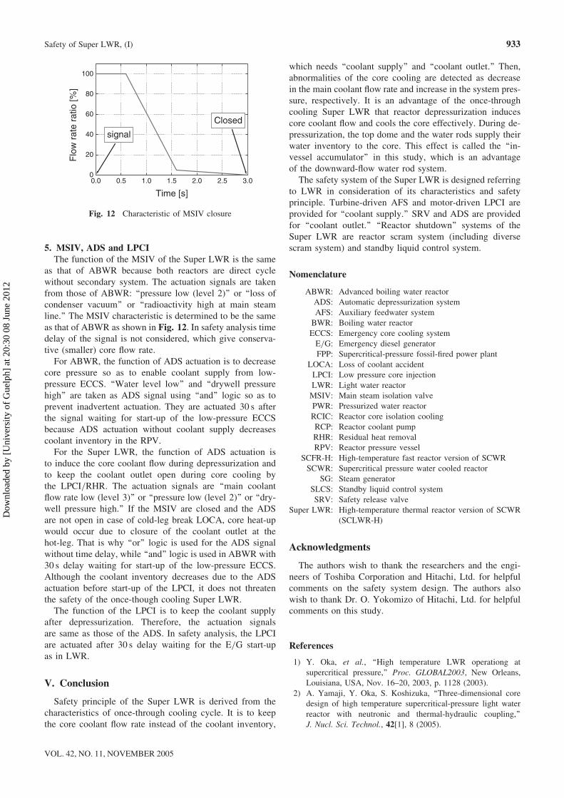
as that of ABWR because both reactors are direct cyclewithout secondary system. The actuation signals are takenfrom those of ABWR: ‘‘pressure low (level 2)’’ or ‘‘loss ofcondenser vacuum’’ or ‘‘radioactivity high at main steamline.’’ The MSIV characteristic is determined to be the sameas that of ABWR as shown in Fig. 12. In safety analysis timedelay of the signal is not considered, which give conserva-tive (smaller) core flow rate.
For ABWR, the function of ADS actuation is to decreasecore pressure so as to enable coolant supply from low-pressure ECCS. ‘‘Water level low’’ and ‘‘drywell pressurehigh’’ are taken as ADS signal using ‘‘and’’ logic so as toprevent inadvertent actuation. They are actuated 30 s afterthe signal waiting for start-up of the low-pressure ECCSbecause ADS actuation without coolant supply decreasescoolant inventory in the RPV.
For the Super LWR, the function of ADS actuation isto induce the core coolant flow during depressurization andto keep the coolant outlet open during core cooling bythe LPCI/RHR. The actuation signals are ‘‘main coolantflow rate low (level 3)’’ or ‘‘pressure low (level 2)’’ or ‘‘dry-well pressure high.’’ If the MSIV are closed and the ADSare not open in case of cold-leg break LOCA, core heat-upwould occur due to closure of the coolant outlet at thehot-leg. That is why ‘‘or’’ logic is used for the ADS signalwithout time delay, while ‘‘and’’ logic is used in ABWR with30 s delay waiting for start-up of the low-pressure ECCS.Although the coolant inventory decreases due to the ADSactuation before start-up of the LPCI, it does not threatenthe safety of the once-though cooling Super LWR.
The function of the LPCI is to keep the coolant supplyafter depressurization. Therefore, the actuation signalsare same as those of the ADS. In safety analysis, the LPCIare actuated after 30 s delay waiting for the E/G start-upas in LWR.
V. Conclusion
Safety principle of the Super LWR is derived from thecharacteristics of once-through cooling cycle. It is to keepthe core coolant flow rate instead of the coolant inventory,
which needs ‘‘coolant supply’’ and ‘‘coolant outlet.’’ Then,abnormalities of the core cooling are detected as decreasein the main coolant flow rate and increase in the system pres-sure, respectively. It is an advantage of the once-throughcooling Super LWR that reactor depressurization inducescore coolant flow and cools the core effectively. During de-pressurization, the top dome and the water rods supply theirwater inventory to the core. This effect is called the ‘‘in-vessel accumulator’’ in this study, which is an advantageof the downward-flow water rod system.
The safety system of the Super LWR is designed referringto LWR in consideration of its characteristics and safetyprinciple. Turbine-driven AFS and motor-driven LPCI areprovided for ‘‘coolant supply.’’ SRV and ADS are providedfor ‘‘coolant outlet.’’ ‘‘Reactor shutdown’’ systems of theSuper LWR are reactor scram system (including diversescram system) and standby liquid control system.
Nomenclature
ABWR: Advanced boiling water reactorADS: Automatic depressurization systemAFS: Auxiliary feedwater systemBWR: Boiling water reactorECCS: Emergency core cooling systemE/G: Emergency diesel generatorFPP: Supercritical-pressure fossil-fired power plant
LOCA: Loss of coolant accidentLPCI: Low pressure core injectionLWR: Light water reactorMSIV: Main steam isolation valvePWR: Pressurized water reactorRCIC: Reactor core isolation coolingRCP: Reactor coolant pumpRHR: Residual heat removalRPV: Reactor pressure vessel
SCFR-H: High-temperature fast reactor version of SCWRSCWR: Supercritical pressure water cooled reactor
SG: Steam generatorSLCS: Standby liquid control systemSRV: Safety release valve
Super LWR: High-temperature thermal reactor version of SCWR(SCLWR-H)
Acknowledgments
The authors wish to thank the researchers and the engi-neers of Toshiba Corporation and Hitachi, Ltd. for helpfulcomments on the safety system design. The authors alsowish to thank Dr. O. Yokomizo of Hitachi, Ltd. for helpfulcomments on this study.
References
1) Y. Oka, et al., ‘‘High temperature LWR operationg atsupercritical pressure,’’ Proc. GLOBAL2003, New Orleans,Louisiana, USA, Nov. 16–20, 2003, p. 1128 (2003).
2) A. Yamaji, Y. Oka, S. Koshizuka, ‘‘Three-dimensional coredesign of high temperature supercritical-pressure light waterreactor with neutronic and thermal-hydraulic coupling,’’J. Nucl. Sci. Technol., 42[1], 8 (2005).
0.0 0.5 1.0 1.5 2.0 2.5 3.00
20
40
60
80
100
Closed
signal
Flo
w r
ate
ratio
[%]
Time [s]
Fig. 12 Characteristic of MSIV closure
Safety of Super LWR, (I) 933
VOL. 42, NO. 11, NOVEMBER 2005
Dow
nloa
ded
by [
Uni
vers
ity o
f G
uelp
h] a
t 20:
30 0
8 Ju
ne 2
012
3) T. Mukohara, et al., ‘‘Core design of a high-temperature fastreactor cooled by supercritical light water,’’ Ann. Nucl. Ener-gy, 26, 1423 (1999).
4) K. Kitoh, et al., ‘‘Pressure and flow-induced accident and tran-sient analysis of a direct-cycle, supercritical-pressure, light-water-cooled fast reactor,’’ Nucl. Technol., 123, 223 (1988).
5) K. Kitoh, et al., ‘‘Refinement of transient criteria and safetyanalysis for a high-temperature reactor cooled by supercriticalwater,’’ Nucl. Technol., 135[3], 252 (2001).
6) Y. Ishiwatari, Y. Oka, S. Koshizuka, ‘‘Safety analysis of a hightemperature supercritical pressure light water cooled andmoderated reactor,’’ Proc. Int. Congress of Advanced NuclearPower Plants (ICAPP), Hollywood, Florida, June 9–13, 2002,No. 1045 (2002).
7) Y. Ishiwatari, Y. Oka, S. Koshizuka, ‘‘Safety analysis of hightemperature reactor cooled and moderated by supercriticallight water,’’ Proc. Int. Conf. on Global Environment and
Advanced Nuclear Power Plants (GENES4/ANP2003), Kyoto,Japan, Sep. 15–19, 2003, No. 1159 (2003).
8) Y. Ishiwatari, Y. Oka, S. Koshizuka, ‘‘LOCA analysis of hightemperature reactor cooled and moderated by supercriticallight water,’’ Proc. Int. Conf. on Global Environment andAdvanced Nuclear Power Plants (GENES4/ANP2003), Kyoto,Japan, Sep. 15–19, 2003, No. 1160 (2003).
9) Y. Ishiwatari, et al., ‘‘ATWS analysis of supercritical pressurelight water cooled reactor,’’ Proc. GLOBAL2003, NewOrleans, Louisiana, USA, Nov. 16–20, 2003, p. 2335 (2003).
10) Y. Ishiwatari, Y. Oka, S. Koshizuka, ‘‘Safety design principleof supercritical water cooled reactors,’’ Proc. 2004 Int.Congress of Advances in Nuclear Power Plants (ICAPP’04),Pittsburg, Pennsylvania, June 13–17, 2004, No. 4319 (2004).
11) Y. Ishiwatari, Y. Oka, S. Koshizuka, ‘‘Safety of Super LWR(II); Safety analysis at supercritical pressure,’’ J. Nucl. Sci.Technol., 42[11], 935 (2005).
934 Y. ISHIWATARI et al.
JOURNAL OF NUCLEAR SCIENCE AND TECHNOLOGY
Dow
nloa
ded
by [
Uni
vers
ity o
f G
uelp
h] a
t 20:
30 0
8 Ju
ne 2
012