Embed Size (px)
Citation preview

681
Safety of Combined Cycle Gas Turbine and Gas Engine Systems Operating on Hydrogen Rich Syngas and Biogas
Hawksworth S. J.1,* , Moodie K.1, Gummer J.1, Ewan B.2, Michels H.3, Linstedt P.3,
Winstanley P.4, Pekalski A.5
1Health and Safety Laboratory, Harpur Hill, Buxton, Derbyshire, UK
2HSL Associate 3Imperial College, Exhibition Road, London, UK
4Energy Technologies Institute, Loughborough, UK 5Shell Global Solutions, UK
*Corresponding author email: [email protected]
ABSTRACT The UK Energy Technologies Institute (ETI) is supporting a multi-partner project to investigate the safe operation of combined cycle power generating systems running on syngas and biogas. The project, led by the UK Health and Safety Laboratory (HSL) looks particularly at hazardous situations that may result in an explosive fuel mixture entering the exhaust and Heat Recovery Steam Generator (HRSG), and igniting. The findings from this work using a large scale experimental facility on the 550 acre HSL site near Buxton, Derbyshire, UK are discussed. The facility simulates the conditions in a HRSG, utilising the exhaust gas from a Rolls-Royce Viper jet-engine to reproduce the temperature and flow conditions. The effects of turbulence generated by the HRSG heat exchangers are reported. Results from the test programme are presented which demonstrate deflagration to detonation transition under certain conditions.
KEYWORDS: Deflagration-to-detonation transition, gas turbine, heat recovery steam generator, hydrogen.
INTRODUCTION
Achieving a secure, sustainable and affordable energy system for the future will clearly require new technologies, as well as improvements and adaptations to those currently in use, such as Combined Cycle Gas Turbine (CCGT) and Combined Cycle Gas Engines (CCGE) systems. Recognising this approach, CCGT and CCGE systems feature strongly in many of the energy plans and energy system modelling exercises of organisations such as the International Energy Agency (IEA) [1], and countries such as Japan [2] and the UK [3].
One clear advantage of CCGT and CCGEs is their ability to operate on a range of potential fuels, including hydrogen rich waste streams such as gas waste streams, clean coal technologies and others employing pre-combustion Carbon Capture and Sequestration (CCS) - see Appendix 1. In the short to medium term such options provide significant benefit in terms of better use of resources (e.g. Waste to Energy applications) and in addition provide a basis for the development of hydrogen based technologies. In the developing hydrogen economy, the headlines obviously focus on fuel cell technologies, and centralised large scale power generation using hydrogen fuel cells also exists in a number of countries [4] and is a clearly a complimentary and growing trend for the future.
With the above in mind the UK Energy Technologies Institute (ETI) is supporting a large multi-partner project investigating the safety of CCGT and CCGE power generation systems operating Proceedings of the Eighth International Seminar on Fire and Explosion Hazards (ISFEH8), pp. 681-690 Edited by Chao J., Liu N. A., Molkov V., Sunderland P., Tamanini F. and Torero J. Published by USTC Press ISBN:978-7-312-04104-4 DOI:10.20285/c.sklfs.8thISFEH.068

Proceedings of the Eighth International Seminar on Fire and Explosion Hazards (ISFEH8)
682
on high hydrogen fuels, including pure hydrogen. The project consortium is led by the UK Health and Safety Laboratory (HSL), which is part of Health and Safety Executivesʼ Science Directorate. The other partners include Imperial College London, and Scitek Ltd based in Derby in the UK.
The first stages of the project gathered and assessed available information relating to the operation of CCGT and CCGE systems, including a detailed survey of critical properties and operational parameters relating to the use of gaseous fuel mixtures. These fuel mixtures were of high hydrogen content within the systems of interest, particularly those with the potential to generate high overpressures under fault conditions in the CCGT and CCGE exhausts and in the HRSG units.
Project scope
This project is currently focusing on the potential for a flame out in GT or GE power unit, leading to flooding of the system downstream of the fuel injection point (exhaust and HRSG) with a flammable gas mix, which could then be ignited. The risks associated with such an occurrence are not insignificant because of the potential variability of the fuel composition of what are, in effect, high hydrogen waste streams. To understand these hazards careful thought has been given to unusual conditions of flow, temperature and scale found in the facilities of interest. Based on these factors and the typical properties of the mixtures identified in Appendix A, a staged program of work was developed focusing on fuel mixtures of H2, CO and CH4. The programme objective is to understand their behaviour under the extreme conditions of flow and temperature found in the exhausts and HRSGs of these systems, and in particular the detonation limits under these conditions.
BACKGROUND TO CCGT AND CCGE SYSTEMS
Combined cycle gas turbines (CCGT)
The operation of Combined Cycle Gas Turbines (CCGT) is currently (using natural gas) one of the most efficient methods (Starr [5]) for converting the energy in gaseous fuels, into electrical energy, achieving efficiencies over 60%. In such systems the CCGT consists of a gas turbine which produces about two thirds of the power. The waste heat in the exhaust system from the gas turbine is then used to raise steam, which powers a steam turbine producing the remaining third of the power. The steam is raised via a HRSG, which is situated in the exhaust stream of the primary turbine, and is connected to it by ducting that also serves to expand the flow in order to obtain appropriate velocities for optimum heat transfer. The exhaust gas temperatures are for various thermodynamic reasons relatively low, in the region of 300-600 ℃. This has resulted in large HRSGs often with two or more evaporators, although larger plants may include up to twelve stages.
The exhaust gas temperature limitations are well recognised. To compensate for this, many industrial scale CCGTs utilise a supplementary duct burner, situated in the gas turbine exhaust. This utilises the residual oxygen in the gas turbine exhaust to raise extra process steam. A fan may be used to supply additional air, which may also enable the burner to be used in the auxiliary mode, whereby it can operate independently to provide heat when the gas turbine is not operating.
The successful operation of gas turbines using syngas (including hydrogen fuel concentrations > 90%) has been demonstrated at numerous facilities over the past few years, although there have been difficulties [6]. The syngas mixtures can vary widely in the relative hydrogen and carbon monoxide concentrations, complicating turbine operation and design. The high-temperatures associated with the hydrogen combustion can lead to high nitrogen oxide emissions, and existing dry low-NOx gas-turbine technologies are not amenable to the high mass flow rates and fuel concentrations (from 15% to 40%) required for syngas mixtures. As a result, the current approach is to fire syngas with high levels of dilution (typically using nitrogen or steam).

Part III Explosion
683
Todd and Battista [7] state that significant progress has been made in the development of market applications for hydrogen fuel use in gas turbines. These applications include integrated gasification combined cycle (IGCC) and other types of process/power plants. Development of a new application using gas turbines for significant reduction of power plant CO2 emissions has initiated extensive efforts to expand the range of hydrogen combustion capabilities. Testing program results also show the feasibility of hydrogen use for 20%-90% CO2 emission reduction with control of NOX emissions to below 10 ppm at 15% oxygen. Investment in significant Waste to Energy to projects [8] confirms the growing interest in such technologies.
Combined cycle gas engines (CCGE)
Typical gas engines used for Combined Cycle Gas Engine (CCGE) type systems are designed from the outset to run on gas (not diesel engine conversions), natural gas, biogas or special gases, and are around 0.25-10 MW in output when used as stationary continuous operation units. Gas engines of this type can achieve 44% efficiency, with very low exhaust emissions. They are very durable and highly reliable in all types of applications, particularly when used for Combined Heat and Power (CHP) applications. They are able to constantly generate the rated output even with variable gas conditions.
Gas engines can usually operate on gases with extremely low calorific value, low methane number and hence a low degree of knock, but also gases with a very high calorific value. Typical gas sources vary from low calorific gas produced in chemical industries, wood gas, pyrolysis gas produced from decomposition of substances by heat (gasification), landfill gas, sewage gas, natural gas, propane and butane which have a very high calorific value. Coke gas is also used as a fuel for gas engines; it is a by-product of coke production from hard coal. Coke gas consists mainly of hydrogen (50% to 60%), methane (15% to 30%) and carbon monoxide, but due to the extremely high hydrogen content of coke gas, specially modified engines are used to generate power from this fuel source. Gas engines are often down rated to utilise higher hydrogen content fuels because of knocking (detonation) in cylinders. The limits on fuel composition are based on auto ignition, since ignition must occur when sparked and not prior to it. The flame speed is also of importance since if it is too high ignition timing is compromised.
Other important HRSG features
In common with gas turbine plant, although less common, a supplementary duct burner, situated in the gas engine exhaust, may be used to raise extra process steam, utilising the residual oxygen in the engine exhaust. A fan may be used to supply additional air, which may enable the burner to be used in the auxiliary mode, whereby it can operate independently to provide heat when the gas engine is not operating.
Another important issue arising from running CCGT/CCGE systems on high hydrogen fuels is the production of high NOx emissions. The primary post-combustion NOx control method is selective catalytic reduction (SCR). Ammonia is injected into the flue gas and reacts with NOx in the presence of a catalyst to produce N2 and H2O. The SCR system is located in the exhaust path, typically within the HRSG where the temperature of the exhaust gas matches the operating temperature of the catalyst. The operating temperature of conventional SCR systems ranges from 250 ℃ to 450 ℃.
The primary reactions occurring in SCR require oxygen, so that catalyst performance is best at oxygen levels above 2%-3%. Several different catalysts are available for use at different exhaust gas temperatures. In use the longest and most common are base metal catalysts, which typically contain titanium and vanadium oxides, and which also may contain molybdenum, tungsten, and other elements.

Proceedings of the Eighth International Seminar on Fire and Explosion Hazards (ISFEH8)
684
Low temperature SCRs have been developed as they are ideal for retrofit applications where they can be located downstream of the HRSG, thus avoiding the potentially expensive retrofit of the HRSG to locate the catalyst within a hotter zone of the HRSG.
High temperature SCR installations, operating at up to 650 ℃, have also been developed. The high operating temperature permits the placement of the catalyst directly downstream of the turbine exhaust flange. High temperature SCRʼs are also used on peaking capacity and base-loaded simple-cycle gas turbines where there is no HRSG. Other potential developments in this area include CCGT systems operating on pure hydrogen and oxygen combustion. See Siemens for more information [9].
PROJECT SCOPE AND PROGRAMME OF WORK
The experimental programme of the project, outlining the approach and facilities now follows.
Laboratory based experiments
Laboratory studies were performed at Imperial College to investigate the impact of fuel reactivity changes on a number of key parameters. To achieve this, experimental configurations were chosen to investigate the relative influence of chemistry and flow. Ignition delay times were measured using a shock tube configuration in order to provide a purely chemical kinetic related measure of reactivity. Auto-ignition in a turbulent shear layer formed between a fuel jet and a stream of hot combustion products was investigated in order to explore the influence of turbulence under conditions that can be correlated with the ignition delay time results, using a configuration related directly to the practical case where reactants are ejected into hot combustion products. Turbulent burning velocities were determined using fractal grid generated turbulence in an opposed jet configuration, in order to determine the strength of turbulent deflagrations as a function of fuel composition. The Deflagration to Detonation (DDT) potential in a turbulent flow was assessed using an obstructed shock tube configuration with explosion over-pressures determined and related to the fuel reactivity and the strength of the turbulent deflagration phase.
The study accordingly provides a comprehensive assessment of fuel reactivity in systems related to the use of hydrogen rich mixtures under CCGT and CCGE relevant conditions and showed the impact of CH4 and CO on the reactivity of the mixtures. The experimental results from these studies are very extensive, and are expected to be published at a later date. Also see reference [10].
Circular duct experiments
Using the findings from the analysis of CCGT and CCGE systems combined with the findings from the laboratory experimental work, an experimental facility has been developed to investigate the flame out of CCGT/CCGE systems and the consequences of unburnt fuel passing through the turbine (in the CCGT case) and into the exhaust system. It has been designed to allow for the circumstances where a hydrogen concentration in the downstream mixture will be in the flammable, potentially detonable region (when fuelled with pure hydrogen), and be at temperatures of the order of 400-600 ℃. Re-ignition in the exhaust system is then assumed to occur and the potential consequences assessed, particularly with reference to the flame acceleration and the detonation propensity of the air/fuel mixtures. This facility provides a reduced scale model of an actual turbine exhaust system, comprising a jet engine, to provide a hot vitiated air flow, and a nominal 600 mm diameter duct, some 12 metres long.

Part III Explosion
685
Figure 1. Schematic of HSL facility. Note that the Heat Recovery Steam Generator was added after the
circular duct work and is discussed in the final section of this paper.
The rationale for using this size of rig is based on the consistent experimental and theoretical evidence for hydrogen mixture compositions with marginal detonation behaviour, for which the detonation cell size is characteristically several times that of a stoichiometric fuel mixture and rises asymptotically towards the detonation limit within a few percent for further mixture dilution. With an established detonation cell width for stoichiometric hydrogen-air of approximately 10 mm at near ambient conditions and a critical channel width for detonation propagation of no more than this, the facility makes it feasible to investigate close to the detonation composition limits, a potential hydrogen detonation with multiple cells across the width of the 600 mm duct.
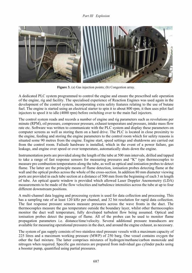
The test facility comprises a Rolls-Royce (R-R) Viper gas turbine, Type 301, the exhaust of which feeds into the 600 mm diameter circular duct, which is 12 metres in overall length (see Fig. 1 above: note that for the circular duct experiments discussed here, the HRSG structure at the end of the circular duct in Fig. 1 was not present and is discussed later in Section 4). The circular duct comprises four 3 m long insulated sections, flanged and bolted together and designed to withstand a maximum operational pressure of 22 barg with a maximum average wall temperature of 400 ℃. An interface section is incorporated between the engineʼs turbine and the start of the 600 mm diameter duct. This provides a pathway from the engine turbine into the duct such that the turbulence levels in the flow are minimised. It also provides a means of controlling the amount of exhaust flow that enters the test duct such that a range of velocities, typical of those found in full size CCGT/CCGE systems, can be replicated. A series of nozzles are integrated into this section to provide a means of injecting and mixing the test gas mixtures radially into the main hot gas exhaust flow from the engine. These gases are injected at about ambient temperature, thus minimising the risk of ignition at this point. The flammable gas/oxygen mixture injection process lasts 2-4 s, during which time ignition of the mixture is obtained using an electrical spark. The flame front then passes down the duct, where it encounters the congestion array shown in Fig. 3(b).

Proceedings of the Eighth International Seminar on Fire and Explosion Hazards (ISFEH8)
686
Figure 2. Rolls-Royce Viper in engine cell.
The Viper jet engine provides a mass flow rate of around 11-15 kg/s, with a turndown ratio of 4:1. The engine has a power output of 3.0-3.5 MW, and jet velocities in the 600 mm diameter duct are between 20-90 m/s. A dedicated mass flow meter type intake ensures that the airflow is smooth and that the mass flow rate can be measured from the pressure drop at the throat of the intake.
The engine output is variable from idle conditions, when the mass flow rate is 3 kg/s, up to maximum power when it is 15 kg/s. Once at or above idle, the exhaust temperatures remain at approximately 560 ℃ until almost the full power output is reached. It is not intended to operate the engine at a mass flow rate of more than 15 kg/s.
The complete test facility comprising the jet engine and the duct, with its associated components housed in an approximately 20 metre long by 3.0 × 3.5 metre cross section ventilated building. The test rig itself is attached directly to a substantial concrete pad, which is capable of withstanding the resulting dynamic reaction loads, should a stoichiometric hydrogen detonation occur within it. The test duct is fixed at one point only, through an anchor plate attached at the beginning of the test duct proper. The rest of the duct is simply supported in order to allow for thermal expansion. The R-R Viper engine is mounted independently with a flexible connection between the exit from the turbine and the entrance to the test duct to minimise exhaust spillage and allow for thermal expansion.
The jet engine has been converted to run on butane in order to minimise the possibility of soot particles affecting the DDT behaviour of the gases being tested. Consequently the design of the gas turbine rig required modification of the engine prior to commencing the test programme and obtaining a 9000 litre liquid butane storage tanks for the duration of the test programme. Modifications to the engine to run on butane involved the removal of its existing fuel pump and fitting an external variable speed positive displacement pump to meter the fuel flow into the engine and therefore control its speed. To this end expertise from Reaction Engines, who have specialised knowledge of running a Viper engine on butane, was obtained so that the risks of any unforeseen technical difficulties arising from the conversion of the engine were minimised.
Part III Explosion
687
Figure 3. (a) Gas injection points; (b) Congestion array.
A dedicated PLC system programmed to control the engine and ensure the prescribed safe operation of the engine, rig and facility. The specialised experience of Reaction Engines was used again in the development of the control system, incorporating extra safety features relating to the use of butane fuel. The engine is started using an electrical starter to spin it to about 800 rpm; it then uses pilot fuel injectors to spool it to idle (4000 rpm) before switching over to the main fuel injectors.
The control system reads and records a number of engine and rig parameters such as revolutions per minute (RPM), oil pressure, compressor pressure, exhaust temperature and pressure, intake mass flow rate etc. Software was written to communicate with the PLC system and display these parameters on computer screens as well as storing them on a hard drive. The PLC is located in close proximity to the engine, feeding and storing the engine parameters to the control room which for safety reasons is situated some 90 metres from the engine. Engine start, speed settings and shutdowns are carried out from the control room. Failsafe hardware is installed, which in the event of a power failure, gas leakage, and engine over speed or over temperature, automatically shuts down the engine.
Instrumentation ports are provided along the length of the tube at 500 mm intervals, drilled and tapped to take a range of fast response sensors for measuring pressures and “K” type thermocouples to measure pre combustion temperatures along the tube, as well as optical and ionisation probes to detect flame. The latter are the principle means of flame detection, ionisation probes detecting flame at the wall and the optical probes across the whole of the cross-section. In addition 80 mm diameter viewing ports are provided in each tube section at a distance of 500 mm from the beginning of each 3 m length of tube. An optical quartz window is provided which allowed Laser Doppler Anemometry (LDA) measurements to be made of the flow velocities and turbulence intensities across the tube at up to four different downstream positions.
A multi-channel data logging and processing system is used for data collection and processing. This has a sampling rate of at least 120 kHz per channel, and 32 bit resolution for rapid data collection. The fast response pressure sensors measure pressures across the wave fronts in the duct. The thermocouples measure the gas temperature outside the boundary layer, whilst other thermocouples monitor the duct wall temperature, fully developed turbulent flow being assumed. Optical and ionisation probes detect the passage of flame. All of the probes can be used to monitor flame propagation parameters i.e. distance/time/velocity. Several additional pressure transducers are available for measuring operational pressures in the duct, and around the engine exhaust, as necessary.
The system of gas supply consists of two stainless steel pressure vessels with a maximum capacity of 225 litres and a maximum working pressure (MWP) of 250 barg. One vessel contains oxygen the other the fuel mixture. The latter comprises mixtures of hydrogen/methane/carbon monoxide and nitrogen when required. Specific gas mixtures are prepared from individual gas cylinder packs using a booster pump, quantified using partial pressures.
Proceedings of the Eighth International Seminar on Fire and Explosion Hazards (ISFEH8)
688
The injecting of the gas mixtures in a flow through system, injecting directly into the exhaust stream (See Fig. 3(a) above) and relying on the injection process to ensure that the gases are fully mixed with the exhaust stream. This avoids waste and reduces the risk of a flash back. The mass flow rates of the injected gases are measured using individual Coriolis mass flow meters, and controlled using mass flow controllers. The supply line pressures are regulated using pressure regulators (40 barg maximum). The same method of flow control is used with the addition of oxygen. The maximum mass flow rate from the fuel system is 2.74 kg/s when operating with 100% CO. The gas supply system is located in a well-ventilated area and is piped to the rig, with protective barriers between for safety reasons. The pipe work and its associated pressure regulators and flow controllers are designed and installed in accordance with the Pressure Systems Regulations, incorporating non-return valves as opposed to flame arrestors.
DISCUSSION - EXPERIMENTAL APPROACH AND PRELIMINARY RESULTS
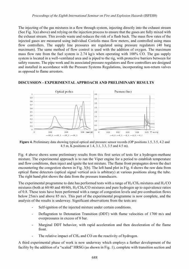
Figure 4. Preliminary data showing typical optical and pressure sensor records (OP positions 1.5, 3.5, 4.2 and
4.5 m, K positions at 1.4, 3.1, 3.3, 3.5 and 4.5 m).
Fig. 4 above shows some preliminary results from this first series of tests for a hydrogen-methane mixture. The experimental approach is to run the Viper engine for a period to establish temperature and flow conditions, then inject and ignite the test mixture. The flame front propagates down the duct encountering the congestion shown in Fig. 3(b). The left hand plot in Fig. 4 shows the raw data from optical flame detectors (optical signal vertical axis is arbitrary) at various positions along the tube. The right hand plot shows the data from the pressure transducers.
The experimental programme to date has performed tests with a range of H2/CH4 mixtures and H2/CO mixtures (both at 60/40 and 40/60), H2/CH4/CO mixtures and pure hydrogen up to equivalence ratios of 0.8. These tests have been performed with a range of congestion levels and pre-combustion flows below 25m/s and above 85 m/s. This part of the experimental programme is now complete, and the analysis of the results is underway. Significant observations from the tests are:
- Self-ignition of the injected mixture under certain conditions.
- Deflagration to Detonation Transition (DDT) with flame velocities of 1700 m/s and overpressures in excess of 8 bar.
- Marginal DDT behavior, with rapid acceleration and then deceleration of the flame front.
- The relative impact of CH4 and CO on the reactivity of hydrogen.
A third experimental phase of work is now underway which employs a further development of the facility by the addition of a “scaled” HRSG (as shown in Fig. 1), complete with transition section and
Part III Explosion
689
tube bundle giving 40% congestion. This addition is combined with other improvements to the increase the gas delivery capacity and injection rates of the system. This updated facility is now commissioned and testing is planned to start in early 2016.
ACKNOWLEDGEMENTS
The work described in this paper was funded by the UK Energy Technologies Institute. The authors would also like to acknowledge the invaluable work of the Scitek Ltd team, Mr Fabian Hampp at Imperial College and the wider project team at HSL including Wayne Rattigan, Louise OʼSullivan and Matt Clay.
REFERENCES 1. International Energy Agency. Hydrogen Implementing Agreement, R&D Gaps and Priorities, OECD/IEA,
2006. 2. Agency for Natural Resources and Energy. Summary of the Strategic Road Map for Hydrogen and Fuel Cells,
International Energy Agency Hydrogen Implementation Agreement, 2014. 3. Heaton, C. Modelling Low-Carbon Energy System Designs with the ETI ESME Model, Modelling, Energy
Technologies Institute, 2014. 4. Website: http://www.powerengineeringint.com/articles/print/volume-22/issue-7/features/fuel-cell-power-sc
ales-up.htm. 5. Starr, F. Future Challenges for CHP in the UK and Continental Europe, Claverton Energy Research Group,
2010. 6. Walton, S. M., He, X., Zigler, B. T., and Wooldridge, M. S, An Experimental Investigation of the Ignition
Properties of Hydrogen and Carbon Monoxide Mixtures for Syngas Turbine Applications, Proceedings of the Combustion Institute, 31(2): 3147-3154, 2007.
7. Todd, D. M., and Battista, R. A. Demonstrated Applicability of Hydrogen Fuel for Gas Turbines, Proceedings of Gasification 4 the Future, Noordwijk, Netherlands, April 2000.
8. Website: http://www.airproducts.co.uk/microsite/uk/teesvalley/facilities.htm. 9. Website: http://www.siemens.com/innovation/en/news/2010/siemens-researching-hydrogen-gas-turbines.ht
m. 10. Li, T., Hampp, F., and Lindstedt, R. P. Turbulent Explosions in H2 Enriched CO and CH4 Mixtures,
Proceedings of the 25th ICDERS, Leeds, 2015. 11. Wolf, J. J., and Perkovec, M. A. Safety Aspects and Environmental Considerations for a 10 MW
Cogeneration Heavy Duty Gas Turbine Burning Coke Oven Gas with 60% Hydrogen Content, ASME Turbo Expo 92-GT-04, 1992.
12. Dragomir, R., Drnevich, R. F., Morrow, J., Papavassiliou, V., Panuccio, G., and Watwe, R. Technologies for Improved Refinery Gas Utilization, NPRA Meeting, Phoenix, AZAM-10-178, 2010.
13. Demirbas, A. Hydrogen Production from Carbonaceous Solid Wastes by Steam Reforming, Energy Sources Part A: Recovery, Utilization, and Environmental Effects, 30(10): 924-931, 2008.

Proceedings of the Eighth International Seminar on Fire and Explosion Hazards (ISFEH8)
690
APPENDIX A
Table of representative fuel gas sources incorporating hydrogen.
Fuel stream Fuel composition (mol%) CV
(MJ/kg) Avg
Mol Wt Fuel
(kg/(s·MW) H2 CO CH4 HC N2 CO2 H2O
Hydrogen 100 120.00 2.00 0.0083
Syngas 1 14.5 23.6 1.6 49 5.6 5.7 9.47 24.40 0.106
Syngas 2 34.4 35.1 0.3 0 0 30.2 8.21 23.85 0.122
Syngas 3 61.9 26.2 6.9 0 2.2 2.8 25.65 11.53 0.039
Syngas +CCS 47 1 1 41 10 8.85 14.66 0.113
COG 61.6 6 23 2.2 5.4 1.2 42.42 9.60 0.024
Refinery Gas 28 28 34 3.5 6.5 41.00 23.8 0.024
Bio Syngas 18 20 7 2 30 23 6.50 26.5 0.154 Note: Syngases 1 - 3 and Syngas + CCS are taken from Todd, D. M., Battista, R. A., 2000 [4], COG is taken from reference J. Wolf, & M. Perkovec., 1992 [11]. Refinery Gas is taken from R. Dragomir et Al, 2010 [12]. Bio-Syngas is taken from A. Demirbas, 2008[13].