Embed Size (px)
Citation preview
1
2
TABLE OF CONTENTS
INSTALLATION AND ASSEMBLY
Austroflamm: An Overview 3 Safety Precautions 4 Labels 7 EPA Certification Information 8 Parts Illustration 9 Installation Instructions 11 Clearances 12 Chimney Configurations 14 Existing Masonry Chimney 16 OPERATING INSTRUCTIONS / FEATURES
General Operation 21 MAINTENANCE AND CLEANING
Maintenance and Cleaning 23 MISCELLANEOUS User Notes 25 WARRANTY Warranty 26 Warranty Registration Card 27 The Esprit Wood Stove has been tested to and in compliance with UL-1482 and ULC-S627 (the safety listing label is on the back of the stove.)
Tested and Listed by
OMNI-Test Laboratories, Inc. Beaverton, Oregon
SAFETY NOTICE IF THIS WOOD STOVE IS NOT PROPERLY INSTALLED, A HOUSE FIRE MAY RESULT. FOR YOUR SAFETY AND TO REDUCE THE RISK OF FIRE, FOLLOW THE INSTALLATION DIRECTIONS. CONTACT LOCAL BUILDING OR FIRE OFFICIALS ABOUT RESTRICTIONS AND INSTALLATION INSPECTION REQUIREMENTS IN YOUR AREA. PLEASE READ THIS ENTIRE MANUAL BEFORE INSTALLATION AND USE OF THIS WOOD BURNING ROOM HEATER. FAILURE TO FOLLOW THESE INSTRUCTIONS COULD RESULT IN PROPERTY DAMAGE, BODILY INJURY OR EVEN DEATH. SAVE THESE INSTRUCTIONS FOR FUTURE REFERENCE WARNING THIS STOVE IS NOT INTENDED FOR USE IN COMMERCIAL APPLICATIONS. THIS STOVE SHOULD BE INSTALLED BY AN AUTHORIZED SERVICETECHNICIAN. THIS STOVE IS NOT DESIGNED FOR USE IN A MOBILE HOME.
3
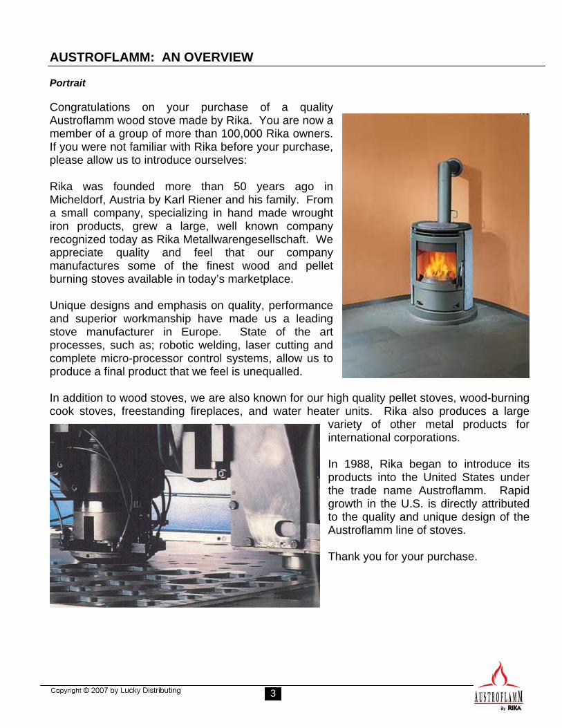
AUSTROFLAMM: AN OVERVIEW Portrait Congratulations on your purchase of a quality Austroflamm wood stove made by Rika. You are now a member of a group of more than 100,000 Rika owners. If you were not familiar with Rika before your purchase, please allow us to introduce ourselves: Rika was founded more than 50 years ago in Micheldorf, Austria by Karl Riener and his family. From a small company, specializing in hand made wrought iron products, grew a large, well known company recognized today as Rika Metallwarengesellschaft. We appreciate quality and feel that our company manufactures some of the finest wood and pellet burning stoves available in today’s marketplace. Unique designs and emphasis on quality, performance and superior workmanship have made us a leading stove manufacturer in Europe. State of the art processes, such as; robotic welding, laser cutting and complete micro-processor control systems, allow us to produce a final product that we feel is unequalled. In addition to wood stoves, we are also known for our high quality pellet stoves, wood-burning cook stoves, freestanding fireplaces, and water heater units. Rika also produces a large
variety of other metal products for international corporations. In 1988, Rika began to introduce its products into the United States under the trade name Austroflamm. Rapid growth in the U.S. is directly attributed to the quality and unique design of the Austroflamm line of stoves. Thank you for your purchase.
4
SAFETY PRECAUTIONS
We welcome you as a new owner of an Austroflamm Esprit wood burning stove. This manual will explain the installation, operation and maintenance of the Esprit stove. Please familiarize yourself with the owner’s manual before operating your stove and save the manual for future reference. The Austroflamm Esprit freestanding wood stove must be properly installed in order to prevent the possibility of a house fire. For your own safety, you must adhere strictly to the installation instructions. Contact your local building officials to obtain a permit and information on any installation restrictions and inspection requirement in your area. Failure to follow these instructions could result in a house fire, property damage, bodily injury or death.
Build-up of soot and creosote in the chimney connector and in the exhaust vent can cause a house fire. It is recommended that the chimney is inspected and cleaned by a professional chimney sweep on an annual basis.
HOT WHILE IN OPERATION! KEEP CHILDREN, CLOTHING AND FURNITURE AWAY FROM STOVE. DO NOT TOUCH ANY RADIANT SURFACE OF YOUR STOVE. CONTACT WITH STOVE MAY CAUSE SKIN BURNS. DO NOT COOK FOOD, HOT BEVERAGES, OR PLACE ANYTHING ON TOP OF STOVE. DO NOT USE CHEMICALS OR FLUIDS TO START THE FIRE. DO NOT BURN GARBAGE OR FLAMMABLE FLUIDS SUCH AS GASOLINE, NAPHTHA OR ENGINE OIL. DO NOT INSTALL IN A MOBILE HOME!
PLEASE READ THIS ENTIRE MANUAL BEFORE INSTALLING OR USING YOUR STOVE.
Never use gasoline, gasoline-type lantern fuel, kerosene, charcoal lighter fluid or similar liquids to start or “freshen up” a fire in this stove. Keep all flammable liquids well away from the stove when it is in use.
The word “Stove” as used in this manual means the Esprit Freestanding Wood Stove.
DO NOT ABUSE THE DOOR GLASS. USE CARE NOT TO STRIKE THE GLASS WITH OTHER OBJECTS. DO NOT ALLOW THE DOOR TO SLAM SHUT. DO NOT OPERATE YOUR STOVE WITH BROKEN OR DAMAGED DOOR GLASS, OR WITH THE DOOR OPEN!!
DO NOT INSTALL A FLUE DAMPER IN THE CHIMNEY SYSTEM OF THIS STOVE! DO NOT CONNECT THIS STOVE TO A CHIMNEY FLUE CONNECTED TO ANOTHER STOVE OR APPLIANCE. DO NOT CONNECT TO ANY AIR DISTRIBUTION DUCT OR SYSTEM.
5
SAFETY PRECAUTIONS
FLOOR SUPPORT Prior to installation, ensure that the floor and support construction is sufficient to support the weight of the stove.
BE SURE TO ALLOW AN ADEQUATE SOURCE OF FRESH AIR INTO THE ROOM WHERE THE STOVE IS LOCATED. AIR STARVATION CAN CAUSE SMOKE TO ENTER INTO YOUR HOME, AN INABILITY TO MAINTAIN A FIRE, AND IT CAN CAUSE SMOKE DETECTORS TO ACTIVATE. DO NOT OPERATE THE STOVE WITHOUT THE FIREBOX BAFFLE PLATES PROPERLY INSTALLED. BUILD FIRES DIRECTLY UPON THE HEARTH INSIDE THE STOVE. DO NOT USE GRATES, IRONS OR ANY OTHER METHOD TO ELEVATE THE FIRE. THE ESPRIT STOVE IS NOT SUITABLE OR APPROVED FOR FIREPLACE INSTALLATION AND IS DESIGNED TO BE USED ONLY AS A FREE STANDING WOOD STOVE. THE ESPRIT WOOD STOVE IS DESIGNED SPECIFICALLY FOR USE WITH DRY FIREWOOD. DO NOT USE MAKESHIT COMPROMISES DURING INSTALLATION.
FUEL QUANTITIES THE ESPRIT WOOD STOVE IS DESIGNED WITH A FLAT FIREBOX LAYOUT. ONLY ONE LAYER OF FUEL MUST BE PLACED ON THE EXISTING EMBERS WHEN RE-STOKING. NOTE: If greater than one layer of fuel is added to your stove, heat output could exceed design and safety limits of the appliance. This may result in damage to the appliance, a house fire, other personal property damage, personal injury or death.
DO NOT OPERATE YOUR STOVE WITH THE DOOR OPEN! Operating your stove with the door open will allow smoke to enter into the room and can cause smoke detectors to activate. Operating your stove with the door open can cause a house fire and carbon monoxide buildup in your home.
ASH SHAKER MECHANISM The ash shaker mechanism is a grated device found in the bottom of the combustion chamber of your stove. The ash shaker is controlled by the lever located at the bottom left front of the stove. Only operate your stove with the shaker handle pushed completely in so that the shaker grate is in a closed position.
ASH COLLECTION DRAWER (ASH PAN) Your stove is equipped with a gasket sealed ash pan. The ash pan is located inside the door below the combustion chamber. WARNING! Never operate your stove with the ash pan open or removed. Failure to adhere to this warning can cause an over-heating condition resulting in a house fire, property damage, bodily injury or death.
WARNING: DO NOT INSTALL IN A SLEEPING ROOM!
THIS STOVE SHOULD BE INSTALLED BY ANAUTHORIZED SERVICE TECHNICIAN.
6
SAFETY PRECAUTIONS
THE ENAMEL FINISH APPLIED TO YOUR STOVE BECOMES FULLY HARDENED BY HEAT GENERATED DURING THE FIRST SEVERAL HOURS OF USE. To ensure adequate hardening of finished surfaces:
• Do not touch any finished surface during the initial 24-hours of use. The finish will still be soft. Touching the surface during this period of time can cause permanent blemishes in the paint finish.
• A minimal amount of fumes may be
present during initial use. To draw off those fumes, ensure that the area is well ventilated. Do not prepare food in the general vicinity of the stove.
• If fumes become excessive, open a
windows and/or door and use a room fan to create cross ventilation.
• Hardening of the finish will be complete
after several hours of routine use.
Smoke Detectors: Smoke detectors should be installed in at least two locations within your home. If smoke detectors are installed in the general vicinity of your wood stove, the heat generated by the stove can cause your smoke detector to activate.
WARNING! Do not make any alterations to the stove design. Only use factory authorized parts when performing service or making repairs., do not use substitutions. Design alterations or use of non-factory authorized parts could cause damage to your stove, and could result in a fire.
7
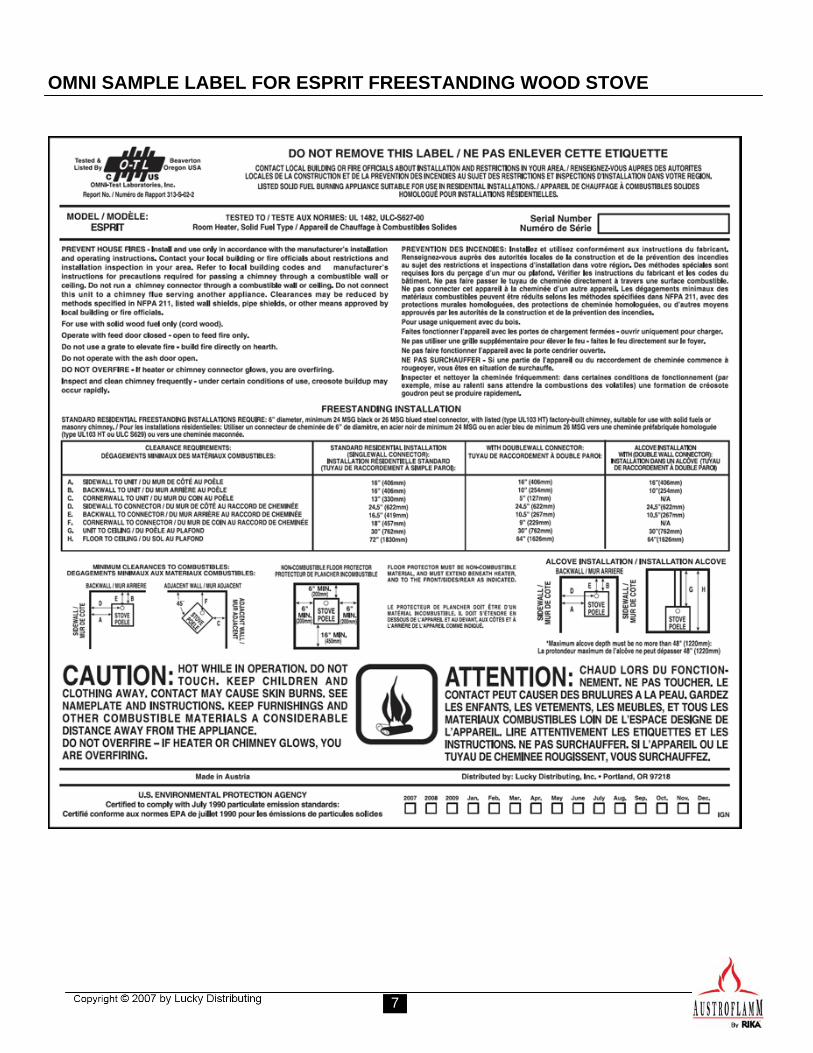
OMNI SAMPLE LABEL FOR ESPRIT FREESTANDING WOOD STOVE
8
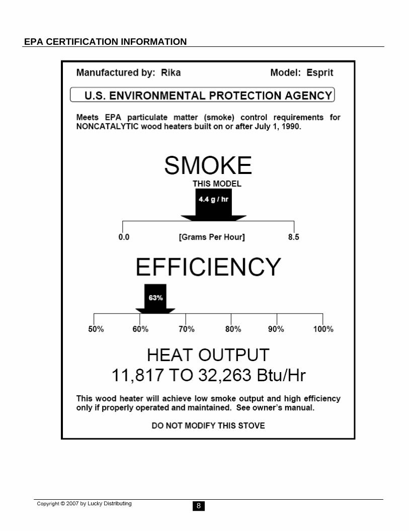
EPA CERTIFICATION INFORMATION
9
PARTS ILLUSTRATIONS
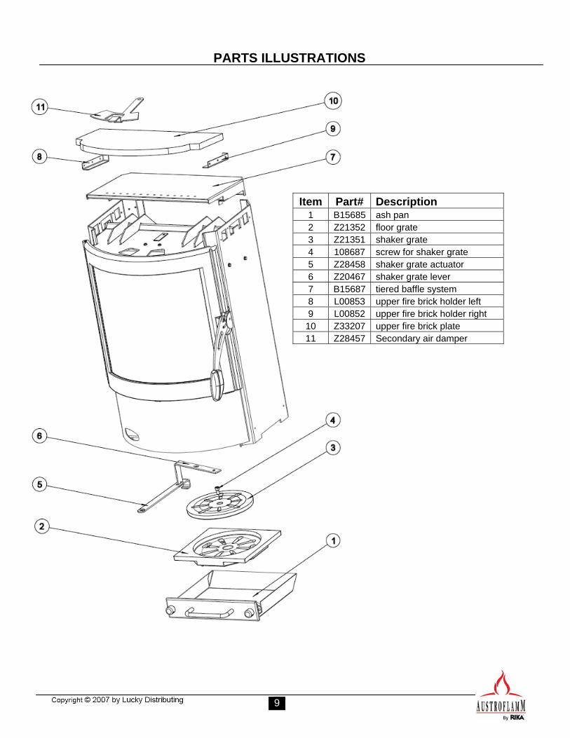
Item Part# Description 1 B15685 ash pan 2 Z21352 floor grate 3 Z21351 shaker grate 4 108687 screw for shaker grate 5 Z28458 shaker grate actuator 6 Z20467 shaker grate lever 7 B15687 tiered baffle system 8 L00853 upper fire brick holder left 9 L00852 upper fire brick holder right
10 Z33207 upper fire brick plate 11 Z28457 Secondary air damper
10
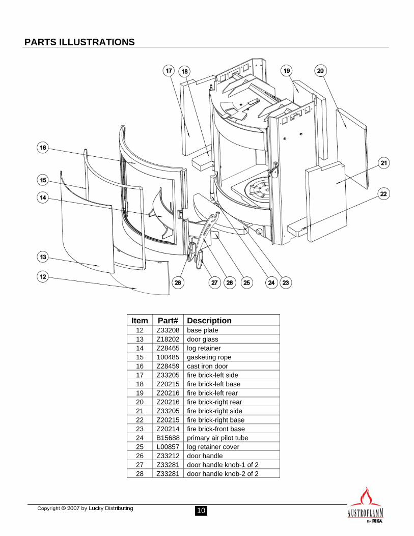
PARTS ILLUSTRATIONS
Item Part# Description 12 Z33208 base plate 13 Z18202 door glass 14 Z28465 log retainer 15 100485 gasketing rope 16 Z28459 cast iron door 17 Z33205 fire brick-left side 18 Z20215 fire brick-left base 19 Z20216 fire brick-left rear 20 Z20216 fire brick-right rear 21 Z33205 fire brick-right side 22 Z20215 fire brick-right base 23 Z20214 fire brick-front base 24 B15688 primary air pilot tube 25 L00857 log retainer cover 26 Z33212 door handle 27 Z33281 door handle knob-1 of 2 28 Z33281 door handle knob-2 of 2
11
INSTALLATION
PRE INSTALLATION CHECK LIST WARNING! This stove should be installed by an authorized installer. Before you begin installation, review your plans. Verify that:
• The stove and chimney connector will be far enough from combustible material to meet all clearance requirements.
• The floor protection is large enough and is constructed properly to meet all requirements.
• All necessary permits from local authoritieshave been attained.
The metal safety label permanently attached to the back of your stove shows that it has been tested to current UL and ULC safety standards, and gives the name of the testing laboratory, as well as certified clearances and additional installation information. Local authorities will generally accept the label as evidence that, when the stove is installed according to the information on the label and in this manual, the installation meets codes and can be approved. However, your local building official is the final authority for approving your installation as safe and determining that it meets all local and state building and safety codes. Codes vary in different areas. Before starting the installation, review your plans with the local governing authorities. Your local dealer should be able to provide any additional information that may be needed.
For any unresolved questions or discrepancies about installation in the USA, refer to the current national Fire Protection Association’s publication ANSI/NFPA 211 Standard for Chimneys, Fireplaces, Vents and Solid Fuel Burning Appliances. For installation in Canada, refer to CSA CAN-B365, Installation Code for Solid Fuel Burning Applications and Equipment. These standards are the basis for many national codes. They are nationally recognized and are accepted by most local authorities. Your local dealer or your local building official may have a copy of these regulations.
WARNING! Check all local building and safety codes before installation. The installation instructions and appropriate code requirements must be followed exactly and without compromise. Do not make alterations to your stove. NOTE: If you plan to vent your stove into an existing masonry chimney, have the chimney inspected by a qualified inspector prior to installation. The chimney and its location can influence stove performance. An oversized flue may not provide effective draught and a flue liner may be required. Consult your dealer or qualified installer before final chimney placement selection is made. It is recommended that you leave enough room to enable cleaning between the stove and the wall. WARNING! Maintain minimum clearance to combustibles as defined further in this manual and which is printed on the safety label located on the back of the stove.
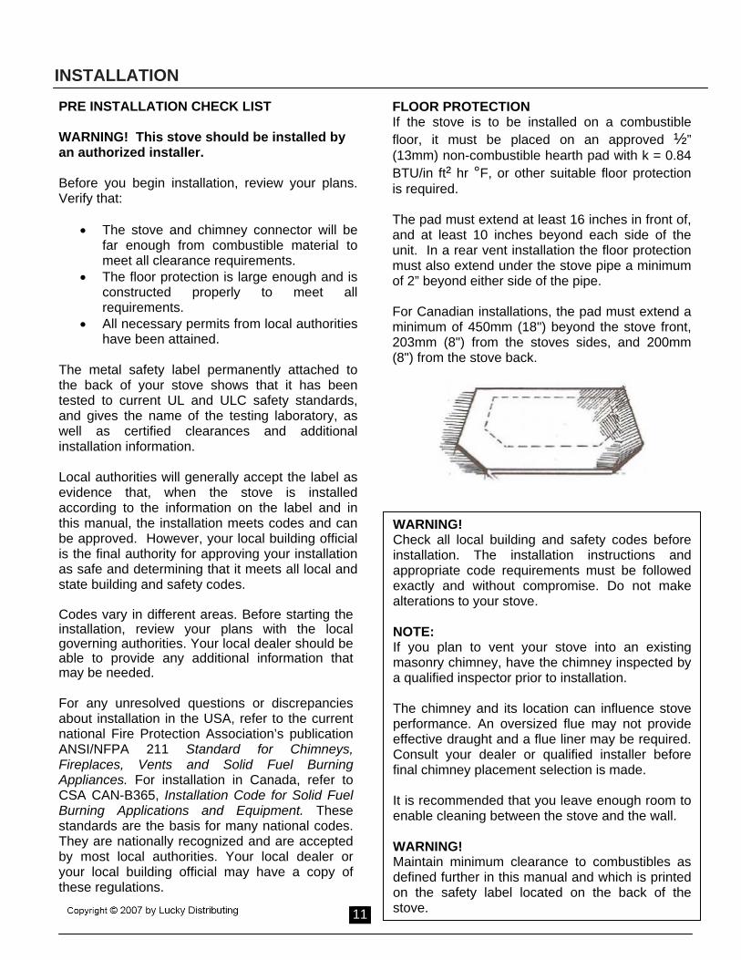
FLOOR PROTECTION If the stove is to be installed on a combustible floor, it must be placed on an approved ½” (13mm) non-combustible hearth pad with k = 0.84 BTU/in ft² hr °F, or other suitable floor protection is required. The pad must extend at least 16 inches in front of, and at least 10 inches beyond each side of the unit. In a rear vent installation the floor protection must also extend under the stove pipe a minimum of 2” beyond either side of the pipe. For Canadian installations, the pad must extend a minimum of 450mm (18") beyond the stove front, 203mm (8") from the stoves sides, and 200mm (8") from the stove back.
12
INSTALLATION CLEARANCES TO COMBUSTIBLES
14
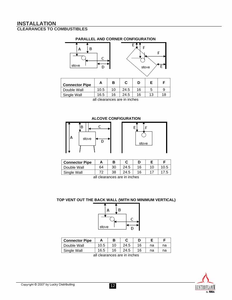
PARALLEL AND CORNER CONFIGURATION
Connector Pipe A B C D E F
Double Wall 10.5 10 24.5 16 5 9 Single Wall 16.5 16 24.5 16 13 18
all clearances are in inches
ALCOVE CONFIGURATION
Connector Pipe A B C D E F Double Wall 64 30 24.5 16 10 10.5 Single Wall 72 38 24.5 16 17 17.5
all clearances are in inches
TOP VENT OUT THE BACK WALL (WITH NO MINIMUM VERTICAL)
Connector Pipe A B C D E F Double Wall 10.5 10 24.5 16 na na Single Wall 16.5 16 24.5 16 na na
all clearances are in inches
13
INSTALLATION CLEARANCES TO COMBUSTIBLES
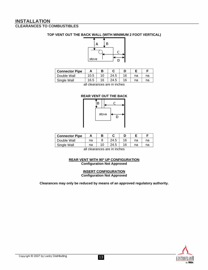
TOP VENT OUT THE BACK WALL (WITH MINIMUM 2 FOOT VERTICAL)
Connector Pipe A B C D E F Double Wall 10.5 10 24.5 16 na na Single Wall 16.5 16 24.5 16 na na
all clearances are in inches
REAR VENT OUT THE BACK
Connector Pipe A B C D E F Double Wall na 8 24.5 16 na na Single Wall na 10 24.5 16 na na
all clearances are in inches
REAR VENT WITH 90º UP CONFIGURATION Configuration Not Approved
INSERT CONFIGURATION
Configuration Not Approved
Clearances may only be reduced by means of an approved regulatory authority.
14
INSTALLATION CHIMNEY CONFIGURATIONS
DO NOT CONNECT THIS UNIT TO A CHIMNEY FLUE SERVING ANOTHER APPLIANCE. DO NOT CONNECT TO ANY AIR DISTRIBUTION DUCT OR SYSTEM. The Esprit Wood Stove installation listing is as a vertically top or rear vented stove using a listed class A (UL103HT) chimney exiting through the ceiling/attic/roof. For Canada (CAN/ULC-S629). The inside of the chimney connector pipe must not be smaller than 6” (152 cm) in diameter. Single wall 24 gauge MSG (0.58 – 0.71 mm) and adapter not smaller than 6” (152 mm), may be used in the room where the stove is installed. In Canada, where passage through a wall or where installation in a partition of combustible construction is intended, the installation mustconform to CAN/CSA B365. When a metal prefabricated chimney is used, the manufacturer’s installation instructions must be followed. You must also install the ceiling support package or wall pass-through and “T” section package, fire stops (where needed or required), insulation shield, roof flashing, chimney cap, etc. Maintain proper clearance to the structure as recommended by the manufacturer and/or local building codes. The chimney must be the required height above the roof or other obstructions for safety and proper draft operation. Masonry Chimney Ensure that a masonry chimney meets the minimum standards of the National Fire Protection Association (NFPA) by having it inspected by a professional. Make sure there are no cracks, loose mortar or other signs of deterioration and blockage. Have the chimney cleaned before the stove is installed and operated. When connecting the stove through a combustible wall to a masonry chimney, special methods are needed. Refer to the following sections of this manual.
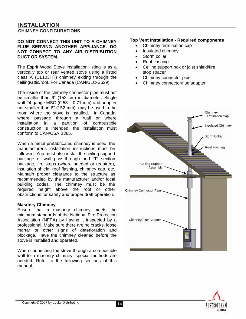
Top Vent Installation - Required components • Chimney termination cap • Insulated chimney • Storm collar • Roof flashing • Ceiling support box or joist shield/fire
stop spacer • Chimney connector pipe • Chimney connector/flue adapter
Chimney Termination Cap
Insulated Chimney
Storm Collar
Roof Flashing
Ceiling Support Assembly
Chimney Connector Pipe
Chimney/Flue Adapter
15
INSTALLATION CHIMNEY CONFIGURATIONS
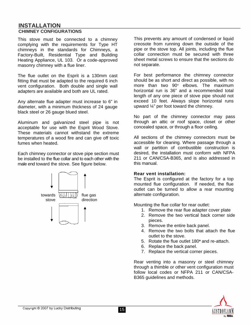
This stove must be connected to a chimney complying with the requirements for Type HT chimneys in the standards for Chimneys, a Factory-Built, Residential Type and Building Heating Appliance, UL 103. Or a code-approved masonry chimney with a flue liner. The flue outlet on the Esprit is a 130mm cast fitting that must be adapted to the required 6 inch vent configuration. Both double and single wall adapters are available and both are UL rated. Any alternate flue adapter must increase to 6” in diameter, with a minimum thickness of 24 gauge black steel or 26 gauge blued steel. Aluminum and galvanized steel pipe is not acceptable for use with the Esprit Wood Stove. These materials cannot withstand the extreme temperatures of a wood fire and can give off toxic fumes when heated. Each chimney connector or stove pipe section must be installed to the flue collar and to each other with the male end toward the stove. See figure below.
towards stove
flue gas direction
This prevents any amount of condensed or liquid creosote from running down the outside of the pipe or the stove top. All joints, including the flue collar connection must be secured with three sheet metal screws to ensure that the sections do not separate. For best performance the chimney connector should be as short and direct as possible, with no more than two 90° elbows. The maximum horizontal run is 36” and a recommended total length of any one piece of stove pipe should not exceed 10 feet. Always slope horizontal runs upward ¼” per foot toward the chimney. No part of the chimney connector may pass through an attic or roof space, closet or other concealed space, or through a floor ceiling. All sections of the chimney connectors must be accessible for cleaning. Where passage through a wall or partition of combustible construction is desired, the installation must conform with NFPA 211 or CAN/CSA-B365, and is also addressed in this manual. Rear vent installation: The Esprit is configured at the factory for a top mounted flue configuration. If needed, the flue outlet can be turned to allow a rear mounting alternate configuration. Mounting the flue collar for rear outlet:
1. Remove the rear flue adapter cover plate 2. Remove the two vertical back corner side
pieces. 3. Remove the entire back panel. 4. Remove the two bolts that attach the flue
outlet to the stove. 5. Rotate the flue outlet 180º and re-attach. 6. Replace the back panel. 7. Replace the vertical corner pieces.
Rear venting into a masonry or steel chimney through a thimble or other vent configuration must follow local codes or NFPA 211 or CAN/CSA-B365 guidelines and methods.
16
INSTALLATION CHIMNEY CONFIGURATIONS
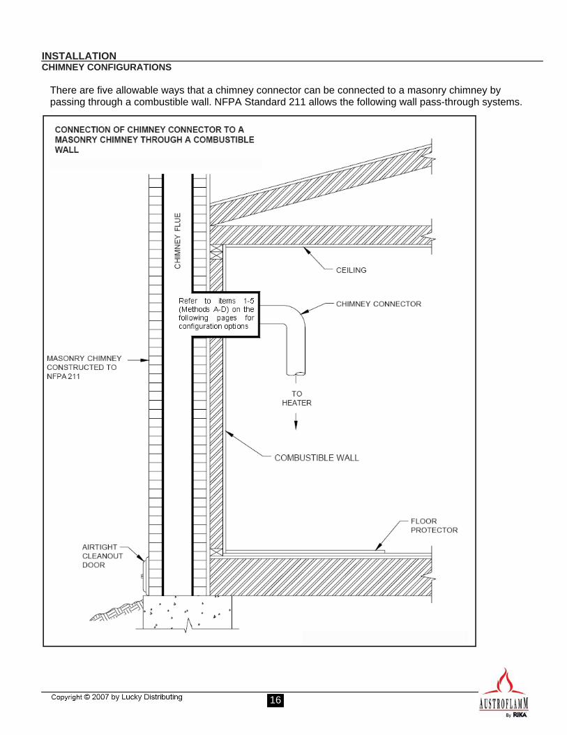
There are five allowable ways that a chimney connector can be connected to a masonry chimney by passing through a combustible wall. NFPA Standard 211 allows the following wall pass-through systems.
17
INSTALLATION CHIMNEY CONFIGURATIONS
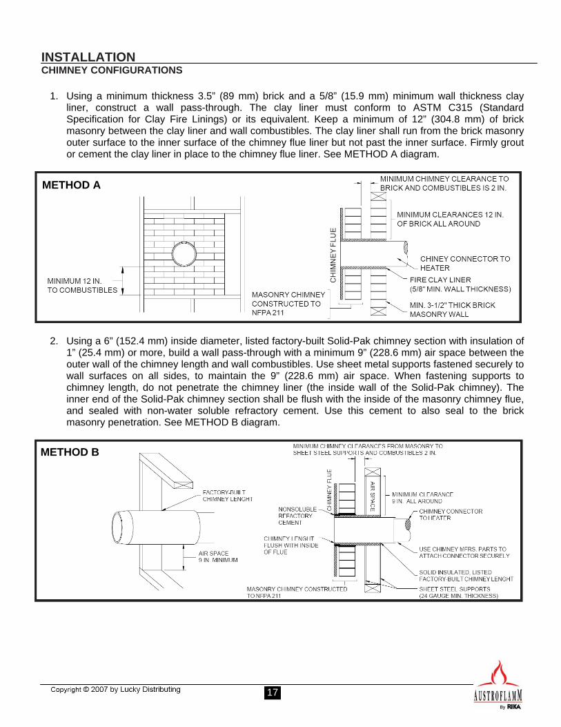
1. Using a minimum thickness 3.5” (89 mm) brick and a 5/8” (15.9 mm) minimum wall thickness clay
liner, construct a wall pass-through. The clay liner must conform to ASTM C315 (Standard Specification for Clay Fire Linings) or its equivalent. Keep a minimum of 12” (304.8 mm) of brick masonry between the clay liner and wall combustibles. The clay liner shall run from the brick masonry outer surface to the inner surface of the chimney flue liner but not past the inner surface. Firmly grout or cement the clay liner in place to the chimney flue liner. See METHOD A diagram.
2. Using a 6” (152.4 mm) inside diameter, listed factory-built Solid-Pak chimney section with insulation of
1” (25.4 mm) or more, build a wall pass-through with a minimum 9” (228.6 mm) air space between the outer wall of the chimney length and wall combustibles. Use sheet metal supports fastened securely to wall surfaces on all sides, to maintain the 9” (228.6 mm) air space. When fastening supports to chimney length, do not penetrate the chimney liner (the inside wall of the Solid-Pak chimney). The inner end of the Solid-Pak chimney section shall be flush with the inside of the masonry chimney flue, and sealed with non-water soluble refractory cement. Use this cement to also seal to the brick masonry penetration. See METHOD B diagram.
METHOD A
METHOD B
18
INSTALLATION CHIMNEY CONFIGURATIONS
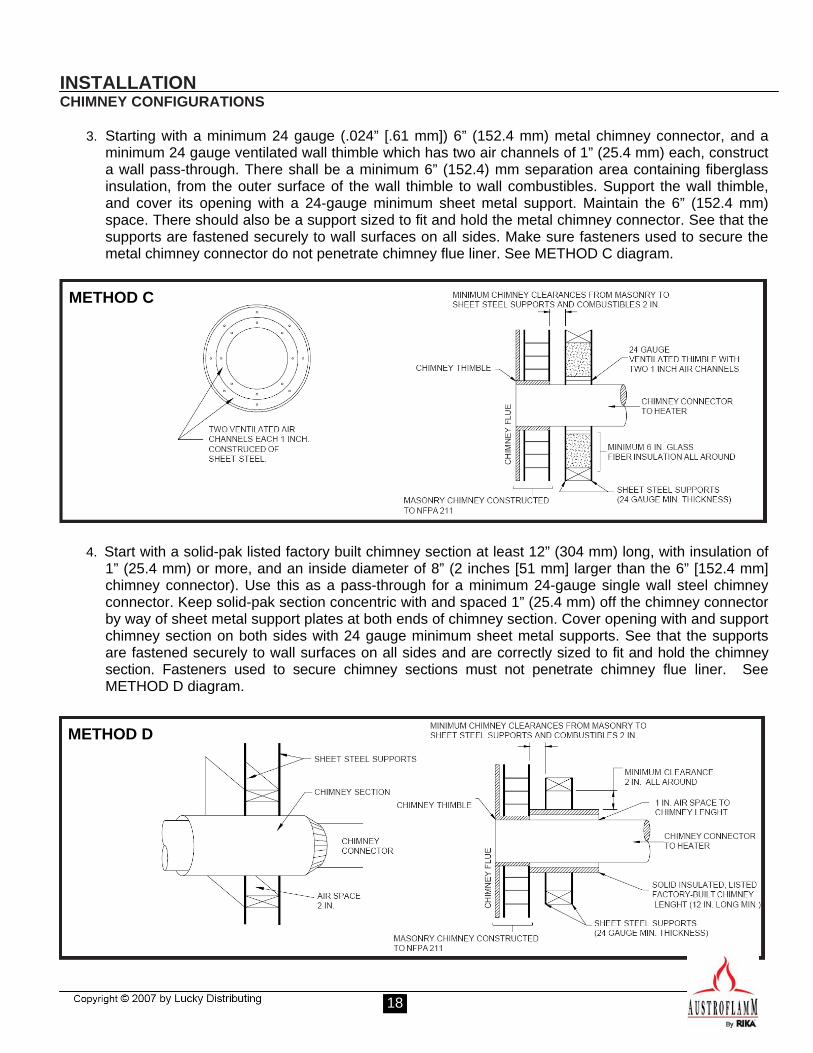
3. Starting with a minimum 24 gauge (.024” [.61 mm]) 6” (152.4 mm) metal chimney connector, and a minimum 24 gauge ventilated wall thimble which has two air channels of 1” (25.4 mm) each, construct a wall pass-through. There shall be a minimum 6” (152.4) mm separation area containing fiberglass insulation, from the outer surface of the wall thimble to wall combustibles. Support the wall thimble, and cover its opening with a 24-gauge minimum sheet metal support. Maintain the 6” (152.4 mm) space. There should also be a support sized to fit and hold the metal chimney connector. See that the supports are fastened securely to wall surfaces on all sides. Make sure fasteners used to secure the metal chimney connector do not penetrate chimney flue liner. See METHOD C diagram.
4. Start with a solid-pak listed factory built chimney section at least 12” (304 mm) long, with insulation of
1” (25.4 mm) or more, and an inside diameter of 8” (2 inches [51 mm] larger than the 6” [152.4 mm] chimney connector). Use this as a pass-through for a minimum 24-gauge single wall steel chimney connector. Keep solid-pak section concentric with and spaced 1” (25.4 mm) off the chimney connector by way of sheet metal support plates at both ends of chimney section. Cover opening with and support chimney section on both sides with 24 gauge minimum sheet metal supports. See that the supports are fastened securely to wall surfaces on all sides and are correctly sized to fit and hold the chimney section. Fasteners used to secure chimney sections must not penetrate chimney flue liner. SeeMETHOD D diagram.
METHOD C
METHOD D
19
INSTALLATION CHIMNEY CONFIGURATIONS
5. A listed factory-built wall pass-through system may be used if installed in accordance with the
manufacturer’s instructions.
Additional requirements pertaining to wall pass-through systems:
1. Insulation material used as part of a wall pass-through system must be a non-combustible material and have a thermal conductivity of 1.0 Btu • in./ft.² • °F (4.88 kg • cal/hr • m² • °C) or less.
2. All clearances and thicknesses are minimums: larger clearances and thickness are acceptable.
3. A chimney thimble, as shown in the diagrams for Methods C and D respectively, must allow for removal of the chimney connector for cleaning. The chimney thimble must be of ASTM C31 5 fireclay with 5/8" minimum wall thickness, or material of equivalent durability. The inside diameter of the thimble must be sized for the snug fit of a 6" diameter chimney connector pipe. The thimble must be installed without damage to the chimney flue. The thimble must extend through the chimney wall, but not beyond the inner surface of the chimney flue. The thimble must be permanently cemented in place with high temperature cement.
4. A chimney connected to a masonry chimney, except for Method B, must extend through the wall pass-through system to the inner face of the chimney flue, but not beyond. It does not have to be fastened in place as long as it cannot accidentally be pulled out of the chimney or shoved into the chimney flue. If fasteners are used to secure the chimney connector to a masonry chimney, the fasteners must not penetrate the chimney flue liner.
5. Any material used to seal any opening or connectors must be noncombustible.
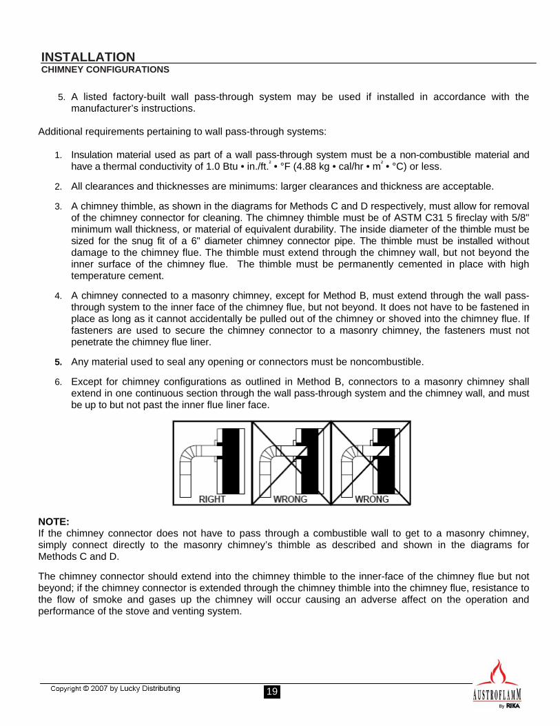
6. Except for chimney configurations as outlined in Method B, connectors to a masonry chimney shall extend in one continuous section through the wall pass-through system and the chimney wall, and must be up to but not past the inner flue liner face.
NOTE: If the chimney connector does not have to pass through a combustible wall to get to a masonry chimney, simply connect directly to the masonry chimney’s thimble as described and shown in the diagrams for Methods C and D.
The chimney connector should extend into the chimney thimble to the inner-face of the chimney flue but not beyond; if the chimney connector is extended through the chimney thimble into the chimney flue, resistance to the flow of smoke and gases up the chimney will occur causing an adverse affect on the operation and performance of the stove and venting system.
20
INSTALLATION CHIMNEY CONFIGURATIONS
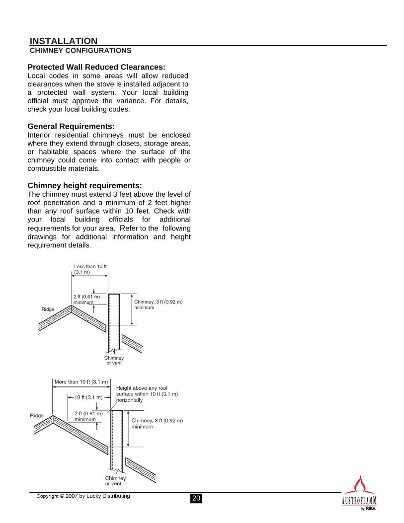
Protected Wall Reduced Clearances: Local codes in some areas will allow reduced clearances when the stove is installed adjacent to a protected wall system. Your local building official must approve the variance. For details, check your local building codes. General Requirements: Interior residential chimneys must be enclosed where they extend through closets, storage areas, or habitable spaces where the surface of the chimney could come into contact with people or combustible materials. Chimney height requirements: The chimney must extend 3 feet above the level of roof penetration and a minimum of 2 feet higher than any roof surface within 10 feet. Check with your local building officials for additional requirements for your area. Refer to the following drawings for additional information and height requirement details.
21
GENERAL OPERATION
Ash Pan: The ash pan located behind the fuel door is designed to make cleaning easier by containing the ashes in a removable drawer. The ash pan should be emptied on a regular basis. Frequency will depend upon fuel and how often the stove is used.
Ash Shaker Grate: Above the ash pan located in the floor of the firebox is a rotating ash or “shaker” grate to facilitate transferring ashes from the firebox into the ash drawer. To operate this grate, push in and pull out the handle that protrudes through the door on the lower left side of the stove. Repeating the lever action several times will increase the amount of ash that falls into the pan and will aid in better operation of the stove. WARNING! Operate the ash shaker only when the stove is cool and all embers fully extinguished. NOTE: Under normal operation, the handle should be pushed all the way in.
Baffle Plates: The Esprit stove has a stainless steel baffle installed in the upper portion of the firebox. The baffle is a vital component of the combustion process of the stove for both the quality of burn and in the reduction of emissions. Do not operate your stove without the baffle system in place. WARNING! Excessive heat due to over-firing can cause damage to the baffle.
Glass: The glass is a heat resistance ceramic that can withstand continuously high temperatures.
The Esprit stove is designed to provide a flow of air over the inside of the glass. This air combined with high temperatures helps keep the glass optimally clean. When operating the stove on low for extended periods of time, the glass may become dirty with soot.
A short, hot fire will help clean off much of the normal soot buildup.
Using dry, well seasoned firewood will help keep the glass soot free. Fire Brick: The firebox in your woodstove comes with a layer of specially designed brick material that shields the outer metal housing of your stove from excessive heat buildup from the firebox. This also aids in a more consistent heat reaching the metal housing of the stove, creating more consistent radiant heat on all of the metal surfaces. Little cracks may develop in the firebrick due to normal use. These cracks do not influence the workability of the stove and are not covered by the limited warranty. Ceramic Door Gasket Rope: Esprit stoves are equipped with a ceramic rope style gasket around the inside perimeter of the door. This gasket will wear out over time. Please consult your authorized dealer for assistance should the gasket become broken or damaged.
Combustion Air Supply: Proper ventilation is essential when using a solid fuel-burning appliance. The combustion process uses oxygen from inside the dwelling. If there is not adequate make-up air (such as in newer homes which are well insulated and weather tight), it may be difficult to obtain an adequate draft in your chimney (caused by a shortage of air in the house). To correct this, it may be necessary to crack a window on the windward side of the dwelling, or provide fresh outside air to a floor or wall vent located near the stove. Secondary Air Intake / Heat Output ControlThe primary air intake is a fixed, non-adjustable system. However, heat output can be regulated by adjusting the secondary air damper. This is done via the control lever located on the top front of the stove. Moving the lever to the left increases air and heat output. Moving the lever to the right decreases air and heat output.
22
GENERAL OPERATION
Opening and Closing the Door WARNING! Wear proper hand protection when opening or closing the door, when starting the fire, and when loading wood. To open the door, lift up on the handle until the latch will disconnect from its corresponding lock pin on main body of the stove. To close, carefully push the door closed and push down on the handle until the latch re-connects to the lock pin The Esprit wood stove is designed with a self closing door. If left open, the door will automatically close but will not automatically re-connect to the lock pin. Fueling the Stove: The Esprit Wood Stove is designed for burning dry, natural, well-seasoned wood only. Wood should be stored in a covered dry place for at least two years before being used for fuel. Cutting and splitting the wood can speed up the drying process. More drying occurs through the end than through the sides even when the wood is split. It is recommended that wood be stacked with both ends exposed. Green or uncured wood does not work well as fuel, and can cause increased creosote buildups. The value of green wood as a source of heat is limited. Do not overload or use kindling or mill ends for primary fuel as this may cause over-firing. Do not store wood or any other combustible material within the installation clearances or within the space required for loading and ash removal. Although feeding excessive amounts of fuel into the stove should be avoided, it is important to supply it with sufficient fuel to maintain a moderately hot fire. This aids in reducing the buildup of creosote in the chimney and aides in minimizing soot buildup on the door glass.
WARNING! Burning materials other than naturally dried, well seasoned wood may shorten the life of your stove and possibly lead to a dangerous over-firing condition. Do not burn garbage, particle board, scraps or pressed logs containing bonding agents because they can produce conditions which will deteriorate stove components. The use of anything other than wood, such as fuels, flammable liquids, grease, etc. can damage your stove and can lead to a house fire.
To Start a Fire: Fully open the secondary air control on the top of the stove. Use a small amount of fire starting material such as an actual fire starter or newspaper, combined with enough kindling wood to establish a small brisk burning fire. Add several larger pieces of wood on top of the burning kindling and allow enough time for it to fully catch on fire. As the stove heats up and creates a sufficient coal bed, adjust the secondary air control to your desired position. CAUTION: Build the fire directly on the hearth inside the stove; do not build a fire above or in front of the log retainer. Refueling: Open the fuel door and add wood then close and latch the fuel door. If the fire or coal bed is almost depleted and a full load of wood is added, it may be necessary to adjust the secondary air intake control wide open to reestablish a lively fire. The use of start up air should only be used for a short period of time.
23
MAINTENANCE AND CLEANING
WARNING! BE SURE THE FIRE IS OUT AND THE STOVE IS COLD BEFORE ANY CLEANING OR MAINTENANCE. WORKING ON OR CLEANING YOUR STOVE WHILE IT’S STILL HOT CAN RESULT IN SERIOUS BURNS. Ash Disposal and Removal: Be careful when you empty ashes from the stove. Embers can remain hot for several hours after the stove is last used. Ashes should be placed in a metal container with a tight fitting lid. The closed container of ashes should be placed on a non-combustible floor or on the ground well away from all combustible materials, pending final disposal. Prior to final disposal, ashes should be kept in the closed container until all embers have thoroughly cooled.
Cleaning Stove Exterior: When the stove is cold, the exterior can be cleaned with a moist cloth. Surface Blemishes: Should your stove become scratched or blemished, touch-up paint is available through your dealer. There may be minor color differences on re-painted surfaces. To minimize this effect it is recommended to re-paint large areas with natural borders. You will get the best result if the stove is repaired while it is hand-warm (if the stove is too hot the paint will be granular). If touch up painting is required, ventilate the area by opening windows and doors, and using a fan for cross-ventilation.
Soapstone: If your stove is equipped with soap stone sides and top, clean the soapstone with a dry sponge. Creosote - Formation and Need for Removal: When wood is burned slowly it produces tar and other organic vapors, which combines with expelled moisture to form creosote. The creosote vapors condense in the relatively cool chimney flue of a slow burning fire. As a result, creosote residue accumulates on the flue lining. When ig-nited, this creosote makes an extremely hot fire.
The chimney and chimney connector should be inspected at least once every two months during the heating season to determine if a creosote buildup has occurred. If creosote has accumulated, it should be removed. Failure to remove creosote may cause a house fire. Creosote may be removed by using a chimney brush or other commonly available materials. For assistance, consult your dealer or a certified chimney sweep. At a minimum your chimney should be cleaned at least one time per heating season. WARNING! Chimney fires burn very hot. If the chimney connector should glow red, immediately call the fire department, then reduce the fire by closing the secondary inlet air control. WARNING! A chimney fire can produce extremely high heat and may cause ignition of wall studs or rafters. If you have a chimney fire, have your chimney inspected by a qualified person before using your stove.
Door Glass: Clean the door glass by wiping it with a dry paper towel or dry, wadded up piece of newspaper. NOTE: Do not use abrasive cleaners to clean the glass. If a glass cleaner is needed, see your stove dealer for a cleaner that is specifically designed for use with wood stoves. Broken or Damaged Glass: If the glass breaks, replace it promptly. Never operate your stove with broken or damaged glass. Use only factory provided ceramic glass in your stove. Do not use other type of glass. If the ceramic glass of your stove needs to be replaced, contact an authorized RIKA dealer for repairs. To replace the glass, make sure that the fire is completely extinguished and the stove is cold. Protect your hands with gloves that are appropriate for this type of work.
24
MAINTENANCE AND CLEANING Unscrew the bolts that hold down the four
stainless-steel frame pieces on the inside of the stove door, then carefully remove the frame pieces one by one. Once the four frame pieces have been removed, the glass should be loose on the door. All of the the glass can now be remove. Dispose of the broken glass in an appropriate manner. Place a new, factory provided sheet of glass into the door, reset the four frame pieces in their original position, then screw the frame pieces back into place. Gasket Replacement: This stove uses rope-type fiberglass gaskets on the inside of the door. Over time the gaskets can become brittle or worn. As this occurs, the effectiveness of the gasket degrades and ultimately the gasket will need to be replaced. Use only factory provided gasket material in your stove. Do not use other type of gaskets. If any gasket material in your stove needs to be replaced, contact an authorized RIKA dealer for repairs. To replace the gasket, make sure the fire is out and the stove is cold. Remove the existing gasket, then clean the area where the gasket attaches. Measure the length of gasket needed by laying it out around the area to be covered, then cut it slightly longer than the needed length. Ensure that the gasket does not unravel when you make the cut.. Place a bead of high-temperature adhesive along the entire area where the gasket sets. Then, beginning at one of the ends, press the gasket into place. Make sure the two gasket ends properly meettogether, then cut to final length. Do not overlap the ends. Firmly press the gasket into place making sure seats in the same position as the original gasket. Clean off any excess adhesive.
Before using the stove, allow the adhesive to set for the amount of time prescribed by the adhesive manufacturer.

25
USER NOTES This page is provided for your use to record operating notes or obvservations.
______________________________________________________________________________________________________________________________________________________________________________________________________________________________________________________________________________________________________________________________________________________________________________________________________________________________________________________________________________________________________________________________________________________________________________________________________________________________________________________________________________________________________________________________________________________________________________________________________________________________________________________________________________________________________________________________________________________________________________________________________________________________________________________________________________________________________________________________________________________________________________________________________________________________________________________________________________________________________________________________________________________________________________________________________________________________________________________________________________________________________________________________________________________________________________________________________________________________________________________________________________________________________________________________________________________________________________________________________________________________________________________________________________________________________________________________________________________________________________________________________________________________________________________________________________________________________________________________________________________________________________________________________________________________________________________________________________________________________________________________________________________________________________________________________________________________________________________________________________________________________________________________________________________________________________________________
26
WARRANTY
Your Esprit Wood Stove is covered by a five year limited warranty. The warranty commences on the date of original purchase. PLEASE TAKE NOTICE THAT THIS WARRANTY APPLIES ONLY TO STOVES PURCHASED FROM LUCKY DISTRIBUTING, INC. OR ONE OF ITS AUTHORIZED DEALERS. LUCKY DISTRIBUTING, INC. MAKE NO WARRANTY IF YOU PURCHASED YOUR STOVE FROM A DEALER OR SELLER NOT AUTHORIZED BY LUCKY DISTRIBUTING, INC. WARRANTY LIMITATIONS: MANUFACTURER, DISTRIBUTOR AND SUPPLIER MAKE NO OTHER WARRANTIES, EXPRESS OR IMPLIED, INCLUDING ANY WARRANTY OF MERCHANTABILITY OR WARRANTY OF FITNESS FOR A PARTICULAR PURPOSE. LIMITATION OF LIABILITY: MANUFACTURER, DISTRIBUTOR AND SUPPLIER SHALL NOT BE LIABLE FOR ANY INCIDENTAL OR CONSEQUENTIAL DAMAGES TO PROPERTY OR PERSONS ARISING FROM OR RELATED TO USE OF THIS PRODUCT. USER’S SOLE AND EXCLUSIVE REMEDY FOR ANY NONCONFORMITY IN THE PRODUCT OR ANY CLAIM RELATED TO THE USE OF THE PRODUCT SHALL BE AT MANUFACTURER’S OPTION, REPAIR OR REPLACEMENT OF THE PRODUCT, OR RETURN OF THE PURCHASE PRICE PAID FOR THE PRODUCT. This warranty covers defects in materials and workmanship in covered components, provided the product has been installed and operated strictly in accordance with the Manufacturer’s printed instructions. This warranty does not cover damage or breakage caused by improper handling, misuse, or unauthorized modification.
There is expressly no warranty on the following components:
• Glass • Firebrick • Baffle system • Shaker Grate • Paint • Metal Plating • Gasket Material • Ceramics and Natural Stone
ALL WARRANTY CLAIMS MUST INCLUDE: 1. Name, address, and telephone
number of the purchaser. 2. Name, address, and telephone
number of the seller, date and proof of purchase.
3. Name, address, and telephone
number of installer, and date of installation.
4. Serial number of the stove. 5. Nature of defect, malfunction, or
complaint. Arrangements will be made for inspection. If the inspection indicates that the failure was due to defective material or workmanship in covered components and that the other terms and conditions of this warranty have been complied with, the Manufacturer’s sole duty and liability under this warranty shall be limited to the Manufacturer’s replacement or repair, at the Manufacturer’s option, of the defective unit or part. The purchaser assumes all costs of shipping to and from the Manufacturer or his agent and shall be responsible for all losses incurred during shipment. Removal and reinstallation costs are not covered under this warranty.
Any warranty implied by law, including, but not limited to, implied warranties of merchantability or fitness, shall be limited to one year from the date of the original purchase. All warranties by the Manufacturer are set forth herein, and no claim shall be made against the Manufacturer based on any oral warranty or representation. The warranty is void if: • the serial number or OMNI safety label
is removed or defaced • service for defects covered under this
warranty is performed by other than an authorized Austroflamm dealer or factory recommended service person
• installation is not in conformity with installation instructions and/or local fire and building regulations
• changes are made to the design characteristics or operating parts. WARNING Such changes may create hazardous conditions which can endanger the user and/or property
Some states do not allow the exclusion or limitation of consequential damages or limitations of implied warranties, so the limitations or exclusions set forth in this warranty may not apply to you.
This warranty gives you specific legal rights, and you may have other rights which vary from state to state.
AUSTROFLAMM/RIKA 8111 NE Columbia Blvd. Portland, OR 97218
27
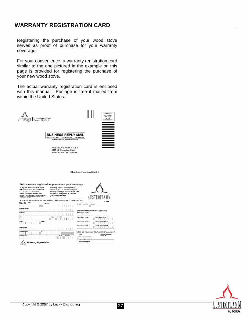
WARRANTY REGISTRATION CARD
Registering the purchase of your wood stoveserves as proof of purchase for your warranty coverage For your convenience, a warranty registration card similar to the one pictured in the example on this page is provided for registering the purchase of your new wood stove. The actual warranty registration card is enclosed with this manual. Postage is free if mailed from within the United States.

28