Embed Size (px)
Citation preview
070220-28 ALT4-LE 100003978
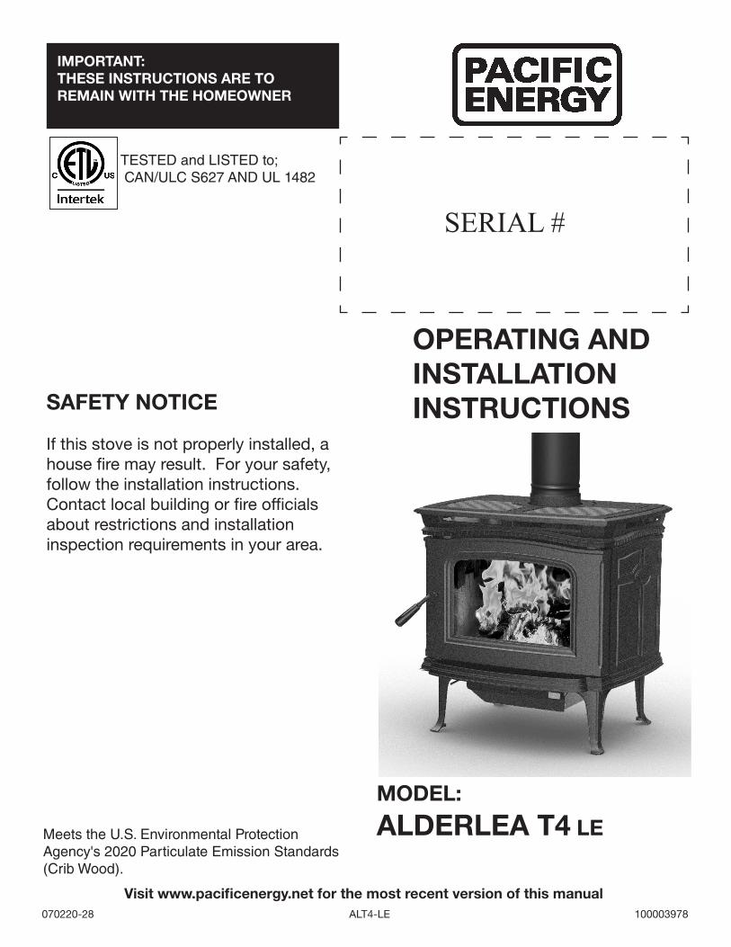
OPERATING AND INSTALLATION INSTRUCTIONSSAFETY NOTICE
If this stove is not properly installed, a house fire may result. For your safety, follow the installation instructions. Contact local building or fire officials about restrictions and installation inspection requirements in your area.
TESTED and LISTED to; CAN/ULC S627 AND UL 1482
IMPORTANT:THESE INSTRUCTIONS ARE TO REMAIN WITH THE HOMEOWNER
MODEL:
ALDERLEA T4 LE
SERIAL #
Visit www.pacificenergy.net for the most recent version of this manual
Meets the U.S. Environmental Protection Agency's 2020 Particulate Emission Standards (Crib Wood).

Experience will give you the right settings for proper combustion and efficient burning. Remember the correct air inlet setting is affected by variables such as type of wood, outside temperature, chimney size and weather conditions. With practice, you will become proficient in operating your heater and will obtain the performance for which it was designed.
Table of Contents
HOT GLASS WILL CAUSE BURNS.
DO NOT TOUCH GLASS UNTIL COOLED.
NEVER ALLOW CHILDREN TO TOUCH GLASS.
! WARNING
PLEASE SAVE THESE INSTRUCTIONS
NOTE: WE STRONGLY RECOMMEND THAT SMOKE AND CARBON MONOXIDE DETECTORS BE INSTALLED IN THE AREA WHERE THE HEATER IS TO BE INSTALLED.If smoke detectors have been previously installed, you may notice that they are operating more frequently. This may be due to curing of stove paint or fumes caused by accidentally leaving the fire door open. Do not disconnect the detectors.
SAFETY NOTICE: If this stove is not properly installed, a house fire may result. For your safety, follow the installation instructions. Contact local building or fire officials about restrictions and installation inspection requirements in you area.Please read this entire manual before you install and use your new room heater. Failure to follow instructions may result in property damage, bodily injury, or even death.
Table of Contents ...................................................................... 2 Rating Label .............................................................................. 3
Efficiency and BTU Output ................................................. 3 Safety ........................................................................................ 4
Chimney Smoke and Creosote Formation ......................... 4Chimney Fires .................................................................... 4To Avoid a Chimney Fire..................................................... 5In the event of a Chimney Fire ........................................... 5Curing of the Paint Finish ................................................... 5
Operation ................................................................................... 6Wood Selection .................................................................. 6DO NOT BURN : ................................................................. 6How to Test Your Wood ...................................................... 6Lighting a fire ...................................................................... 7Normal Operation ............................................................... 7Restarting After Extended or Overnight Burns .................. 8Proper Draft ........................................................................ 8Ash Removal ...................................................................... 8Ash Clean out system: ..................................................... 8Disposal of Ashes............................................................... 8
Maintenance .............................................................................. 9 Maintenance Checks ............................................................... 10
Weekly: ............................................................................. 10Monthly ............................................................................ 10When Cleaning the Chimney System: .............................. 10Blower: ............................................................................. 10Baffle: ............................................................................... 10
Baffle / Tube Removal ............................................................. 11Tube / Baffle Board Removal ......................................... 11Installation ........................................................................ 11
Assembly ................................................................................. 12 Dimensions .............................................................................. 12 Floor Protector ........................................................................ 13 Residential Installation ............................................................. 14
Clearances: ...................................................................... 14Chimney and Connector .................................................. 15When using a Double-Wall Connector ............................. 15When using a Single-Wall (smoke pipe) Connector ......... 15
Combustion Air ........................................................................ 16Installation Procedure ...................................................... 16Through Wall Installations (as per NFPA 211) ................. 19
Mobile Home Installation ......................................................... 21 Trouble Shooting ..................................................................... 22 Optional Blower ....................................................................... 23
Blower Operation ............................................................. 23 Firebrick Installation ................................................................ 23 Replacement Parts - Alderlea T4 LE ....................................... 26
WARNING: this product can expose you to chemicals including ceramic fibers, which are known to the state of California to cause cancer,and to carbon monoxide,
which is known to the state of California to cause birth defects or other reproductive harm.
For more information go to www.p65warnings.ca.gov.
This warning is applicable to all PACIFIC ENERGY FIREPLACE PRODUCTS
ALT 4-LE 070220-282100003978

Rating Label PLEASE SAVE THESE INSTRUCTIONS
This manual describes the installation and operation of the;Pacific Energy, ALDERLEA T4 LE and ALDERLEA T4 LE Classic freestanding wood heater.
SAFETY NOTICE: If this stove is not properly installed, a house fire may result. For your safety, follow the installation instructions. Contact local building or fire officials about restrictions and installation inspection requirements in you area.
Please read this entire manual before you install and use your new room heater. Failure to follow instructions may result in property damage, bodily injury, or even death.
1 Weighted Average Lower Heating Value (LHV) efficiency as tested using CSA B415 Performance testing of solid-fuel-burning heating appliances. LHV assumes the moisture is already in a vapour state so there is no loss of energy
2 Weighted Average Higher Heating Value (HHV) efficiency as tested using CSA B415 Performance testing of solid-fuel-burning heating appliances. HHV includes the energy required to vaporize the water in the fuel
3 The range of BTU outputs is based on efficiency using CSA B415 Performance testing of solid-fuel-burning heating appli-ances and burn rates from the low and high EPA tests using Douglas Fir dimensional lumber.
This heater meets the U.S. Environmental Protection Agency's 2020 crib wood emission limits for wood heaters sold after May 15, 2020 using Method 28R.
Under specific test conditions this heater has been shown to deliver heat at rates ranging from 13,500 to 23,200Btu/hr.
Emissions testing was performed by PFS-TECO Inc.
EPA Certified Emissions 1.9 grams per hour
LHV Tested Efficiency 1 78%
HHV Tested Efficiency 2 72%
EPA BTU Output 3 13,494 to 23,186 btu/hr.
Maximum Wood Length 18 inches
Ideal Wood Length 16 inches
Fuel Seasoned Cord wood
Efficiency and BTU Output
A.
10 in
. / 3
56 m
m B
.
10
in. /
229
mm
C.
7 in
. / 1
52 m
mVI
STA
LE D
.
19-1
/2 in
. / 6
10 m
m
E.
14-3
/8 in
. / 3
68 m
m
F.
16-1
/2 in
. / 4
29 m
m
ALDE
RLEA
T4 LE
D.
2
5.6
in. /
650
mm
E.
*14.
6 in
. / 3
71 m
m
F.
*17.
1 in
. / 4
35 m
m
CER
TIFI
ED F
OR
CA
NA
DA
AN
D U
.S.A
. - M
OD
EL /
MO
DÈL
E: V
ISTA
LE
VI
STA
CLA
SSIC
LE
A
LDER
LEA
T4 L
E
LIST
ED R
OO
M H
EATE
R, S
OLI
D F
UEL
TYP
E. A
LSO
FO
R U
SE IN
MO
BIL
E H
OM
ESC
ERTI
FIED
TO
/ C
ERTI
FIÉ
POU
R: C
AN
/ULC
S62
7-00
(R20
16) /
UL
1482
-201
1 R
efer
to In
tert
ek’s
Dire
ctor
y of
Bui
ldin
g Pr
oduc
ts fo
r det
aile
d in
form
atio
n
• FO
R U
SE W
ITH
SO
LID
FU
EL (C
OR
DW
OO
D )
ON
LY. D
O N
OT
USE
OTH
ER F
UEL
TYP
ES.
INST
ALL
AN
D U
SE
IN A
CC
OR
DA
NC
E W
ITH
TH
E M
AN
UFA
CTU
RER
’S IN
STA
LLAT
ION
AN
D O
PER
ATIN
G IN
STR
UC
TIO
NS.
• C
ON
TAC
T LO
CA
L B
UIL
DIN
G O
R F
IRE
OFF
ICIA
LS A
BO
UT
RES
TRIC
TIO
NS,
INST
ALL
ATIO
N P
ERM
IT A
ND
INSP
ECTI
ON
IN Y
OU
R A
REA
.•
DO
NO
T C
ON
NEC
T TH
IS U
NIT
TO
A C
HIM
NEY
FLU
E SE
RVIN
G A
NO
THER
APP
LIA
NC
E.•
USE
6 IN
CH
/ 15
0MM
DIA
MET
ER M
INIM
UM
24
MSG
BLA
CK
OR
LIS
TED
CO
NN
ECTO
R.
• U
NIT
CA
N B
E C
ON
NEC
TED
TO
A L
INED
MA
SON
RY C
HIM
NEY
SU
ITA
BLE
FO
R U
SE W
ITH
SO
LID
FU
ELS.
• D
O N
OT
OB
STR
UC
T TH
E SP
AC
E B
ENEA
TH T
HE
HEA
TER
. •
DO
NO
T R
OU
TE P
OW
ER C
OR
D B
ENEA
TH H
EATE
R.
• SE
E LO
CA
L B
UIL
DIN
G C
OD
E A
ND
MA
NU
FAC
TUR
ER'S
INST
RU
CTI
ON
S FO
R P
REC
AU
TIO
NS
REQ
UIR
ED
WH
EN P
ASS
ING
A C
HIM
NEY
TH
RO
UG
H A
CO
MB
UST
IBLE
WA
LL O
R C
EILI
NG
.•
DO
NO
T PA
SS A
CH
IMN
EY C
ON
NEC
TOR
TH
RO
UG
H A
CO
MB
UST
IBLE
WA
LL O
R C
EILI
NG
.•
MIN
IMU
M C
LEA
RA
NC
E B
ETW
EEN
SIN
GLE
WA
LL C
HIM
NEY
CO
NN
ECTO
R A
ND
CO
MB
UST
IBLE
M
ATER
IALS
-18I
NC
HES
/455
MM
. C
LEA
RA
NC
E M
AY B
E R
EDU
CED
BY
THE
USE
OF
LIST
ED P
IPE
SHIE
LDS,
W
ALL
PR
OTE
CTO
RS
OR
OTH
ER M
EAN
S A
PPR
OVE
D B
Y LO
CA
L B
UIL
DIN
G O
R F
IRE
OFF
ICIA
LS.
• C
OM
PON
ENTS
REQ
UIR
ED F
OR
MO
BIL
E H
OM
E IN
STA
LLAT
ION
: OU
TSID
E A
IR K
IT.
• H
OR
IZO
NTA
L C
ON
NEC
TOR
NO
T PE
RM
ITTE
D IN
MO
BIL
E H
OM
ES•
BO
TH C
HIM
NEY
SYS
TEM
AN
D C
ON
NEC
TOR
MU
ST B
E LI
STED
TO
:
IN C
AN
AD
A -
ULC
S-6
41 L
ISTE
D C
ON
NEC
TOR
AN
D U
LC-S
-629
LIS
TED
CH
IMN
EY
IN C
AN
AD
A -
ULC
S-6
41 L
ISTE
D C
ON
NEC
TOR
AN
D U
LC-S
-629
LIS
TED
CH
IMN
EY
IN U
SA -
UL-
103
HT
LIST
ED C
ON
NEC
TOR
AN
D C
HIM
NEY
IN
USA
- U
L-10
3 H
T LI
STED
CO
NN
ECTO
R A
ND
CH
IMN
EY
• U
SE C
OM
PON
ENTS
SPE
CIF
IED
IN P
AC
IFIC
EN
ERG
Y IN
STA
LLAT
ION
INST
RU
CTI
ON
S.•
APP
LIA
NC
E M
UST
BE
INST
ALL
ED W
ITH
PED
ESTA
L O
R L
EG K
IT A
TTA
CH
ED.
• O
PTIO
NA
L C
OM
PON
ENTS
- FA
N K
IT (p
art #
111
4000
1), F
AN
ELE
CTR
ICA
L R
ATIN
G: 1
15V,
60H
Z, 1
.0 A
MP
• D
O N
OT
USE
GR
ATE
OR
ELE
VATE
FIR
E - B
UIL
D W
OO
D F
IRE
DIR
ECTL
Y O
N H
EAR
TH.
• D
O N
OT
OVE
RFI
RE
- IF
CH
IMN
EY O
R C
ON
NEC
TOR
GLO
WS,
YO
U A
RE
OVE
RFI
RIN
G.
• C
AU
TIO
N: R
ISK
OF
EXC
ESSI
VE T
EMPE
RAT
UR
ES -
OPE
RAT
E O
NLY
WIT
H F
EED
DO
OR
CLO
SED
. O
PEN
TO
FEE
D F
IRE
ON
LY. -
KEE
P A
SH D
UM
P C
LOSE
D D
UR
ING
FIR
ING
OF
THE
HEA
TER
. •
KEE
P FU
RN
ISH
ING
S A
ND
OTH
ER C
OM
BU
STIB
LE M
ATER
IALS
WEL
L AW
AY F
RO
M H
EATE
R.
• R
EPLA
CE
GLA
SS O
NLY
WIT
H C
ERA
MIC
GLA
SS.
• C
OM
BU
STIB
LE F
LOO
R M
UST
BE
PRO
TEC
TED
BY
A C
ON
TIN
UO
US
NO
N-C
OM
BU
STIB
LE M
ATER
IAL
EXTE
ND
ED T
O T
HE
FRO
NT,
SID
ES A
ND
BA
CK
AS
IND
ICAT
ED.
• IN
SPEC
T A
ND
CLE
AN
CH
IMN
EY F
REQ
UEN
TLY
- UN
DER
CER
TAIN
CO
ND
ITIO
NS
OF
USE
, CR
EOSO
TE
BU
ILD
UP
MAY
OC
CU
R R
API
DLY
.•
THIS
WO
OD
HEA
TER
NEE
DS
PER
IOD
IC IN
SPEC
TIO
N A
ND
REP
AIR
FO
R P
RO
PER
OPE
RAT
ION
. - C
ON
SULT
TH
E O
WN
ER’S
MA
NU
AL
FOR
FU
RTH
ER IN
FOR
MAT
ION
. •
IT IS
AG
AIN
ST F
EDER
AL
REG
ULA
TIO
NS
TO O
PER
ATE
THIS
WO
OD
HEA
TER
IN A
MA
NN
ER IN
CO
NSI
STA
NT
WIT
H T
HE
OPE
RAT
ING
INST
RU
CTI
ON
S IN
TH
E O
WN
ER’S
MA
NU
AL
* A
S TE
STED
- PI
PE S
HIE
LD M
AY B
E R
EQU
IRED
BY
LOC
AL
AU
THO
RIT
IES.
** C
OM
BU
STIB
LE A
LCO
VE S
IZE:
DEP
TH -
3 FT
. / .9
1 M
MA
X., H
EIG
HT
6 ft.
/ 1.
83 m
MIN
.,
MIN
IMU
M C
LEA
RA
NC
ES T
O
CO
MB
UST
IBLE
MAT
ERIA
LS/
DÉGA
GEME
NTS
MINI
MALE
S AU
X MA
TÉRI
AUX
COMB
USTI
BLES
DO
NO
T R
EMO
VE T
HIS
LAB
EL
RESI
DENT
IAL
and
MOB
ILE
HOM
E IN
STAL
LATI
ON U
SING
DOU
BLE
WAL
L CO
NNEC
TOR
/ IN
STAL
LATI
ON R
ÉSID
ENTI
ELLE
AVE
C DÉ
GAGE
MENT
MIN
IMAL
, UTI
LISA
NT U
N RA
CCOR
D DE
MUR
DOU
BLE
RES
IDEN
TIA
L IN
STA
LLAT
ION
U
SIN
G S
ING
LE W
ALL
CO
NN
ECTO
R*/
INST
ALLA
TION
RÉS
IDEN
TIEL
LE U
TILI
SANT
UN
RAC
CORD
DE
MUR
SIMP
LE
IN C
AN
AD
A G
. 18
INC
HES
/ 45
0 M
M A
U CA
NADA
H
. 8
INC
HES
/ 20
0 M
M
I. 8
INC
HES
/ 20
0 M
M
IN U
.S.A
. G
. 16
INC
HES
/ 40
5 M
M
H.
5 IN
CH
ES /
127
MM
I.
0 IN
CH
ES /
0 M
M
C#4
0015
07•
À UT
ILIS
ER U
NIQU
EMEN
T AVE
C DU
COM
BUST
IBLE
SOL
IDE.
NE
PAS
UTIL
ISER
D’A
UTRE
S TY
PES
DE C
ARBU
RANT
. •
INST
ALLE
Z ET
UTI
LISE
Z SE
LON
LES
INST
RUCT
IONS
D’IN
STAL
LATI
ON E
T D’
OPÉR
ATIO
N FO
URNI
AVE
C L’A
PPAR
EIL.
.•
CONT
ACTE
Z LE
S OF
FICI
ELS
DE L
A CO
NSTR
UCTI
ON O
U DE
SER
VICE
D’IN
CEND
IE P
OUR
DES
INFO
RMAT
IONS
QUA
NT A
UX
REST
RICT
IONS
. PER
MIS
D’IN
STAL
LATI
ON E
T IN
SPEC
TION
S DA
NS V
OTRE
RÉG
ION.
• NE
REL
IEZ
PAS
CET A
PPAR
EIL
À UN
CON
DUIT
DE
CHEM
INÉE
DES
SERV
ANT
DÉJÀ
UN
AUTR
E AP
PARE
IL .
• UT
ILIS
EZ U
N RA
CCOR
DEME
NT N
OIR
OU C
LASS
É DE
24 M
SG E
T AVE
C UN
DIA
MÈTR
E D’
AU M
OINS
6 PO
UCES
/ 150
mm
.•
PEUT
ÊTR
E CO
NNEC
TÉ À
UNE
CHE
MINÉ
E DE
MAÇ
ONNE
RIE
ALIG
NÉE
PRÊT
E À
L’EMP
LOI A
VEC
DES
COMB
USTI
BLES
SOL
IDES
.•
N’OB
STRU
EZ P
AS L
’ESP
ACE
SOUS
LE
CAIS
SON
DU P
OÊLE
• CO
NSUL
TEZ
LE C
ODE
LOCA
L DE
CON
STRU
CTIO
N ET
LES
INST
RUCT
IONS
DU
FABR
ICAN
T QU
ANT A
UX P
RÉCA
UTIO
NS À
PR
ENDR
E LO
RSQU
E VO
US FA
ITES
PAS
SER
UNE
CHEM
INÉE
À T
RAVE
RS D
’UN
MUR
OU D
’UN
PLAF
OND
COMP
OSÉS
DE
MATÉ
RIAU
X CO
MBUS
TIBL
ES.
• NE
FAIT
ES P
AS P
ASSE
R UN
RAC
CORD
EMEN
T DE
CHE
MINÉ
E À
TRAV
ERS
D’UN
MUR
OU
D’UN
PLA
FOND
COM
POSÉ
S DE
MA
TÉRI
AUX
• DÉ
GAGE
MENT
MIN
IMAL
ENT
RE U
N RA
CCOR
DEME
NT D
E CH
EMIN
ÉE À
UN
MUR
SIMP
LE E
T TO
UT M
ATÉR
IEL
COMB
USTI
BLE
- 18 P
OUCE
S / 4
55 m
m. C
E DÉ
GAGE
MENT
PEU
T ÊT
RE R
ÉDUI
T EN
UTI
LISA
NT D
ES P
ROTE
CTEU
RS D
E TU
YAUX
CLA
SSÉS
, PR
OTEC
TEUR
S DE
MUR
OU
AUTR
ES M
OYEN
S AP
PROU
VÉS
PAR
LES
OFFI
CIEL
S DE
LA
CONS
TRUC
TION
OU
DU S
ERVI
CE
D’IN
CEND
IE D
E VO
TRE
RÉGI
ON.
C
ON
NEC
TEU
R H
OR
IZO
NTA
L N
ON
PER
MIS
DA
NS
MA
ISO
NS
MO
BIL
ES•
L’A
PPA
RIE
L D
OIT
CO
MPO
RTE
R U
N E
NSE
MB
LE P
OU
R P
IED
STA
BLE
OU
SU
R P
ATTE
S.•
PIÈC
ES R
EQU
ISES
PO
UR
INST
ALL
ATIO
N E
N M
AIS
ON
MO
BIL
E O
U E
N A
LCÔ
VE:
NÉC
ESSA
IRE
D’A
PPR
OVI
SIO
NN
EMEN
T D
’AIR
EXT
ÉRIE
UR
ET
L’U
N D
ES R
AC
CO
RD
S SU
IVA
NTS
: EN
CO
MB
INA
ISO
N
AVEC
L’U
N D
ES S
YSTÈ
MES
DE
CH
EMIN
ÉE C
OM
PATI
BLE
S SU
IVA
NTS
:
AU
CA
NA
DA
- LE
ULC
S-6
41 C
ON
NEC
TEU
R E
NU
MER
ES E
T U
LC-S
-629
ON
T EN
UM
ERE
CH
EMIN
EE•
PIÈ
CES
EN O
PTIO
N - N
ÉCES
SAIR
ES D
E SO
UFFL
ERIE
, INDI
CES
ÉLEC
TRIQ
UES
DE S
OUFF
LERI
E: 1
15V,
60HZ
, 1.0
AMP.
LE
FIL
ÉLEC
TRIQ
UE N
E DO
IT P
AS Ê
TRE
PLAC
É SO
US L
E PO
ÈTE.
LE
FIL
ÉLEC
TRIQ
UE N
E DO
IT P
AS Ê
TRE
PLAC
É SO
US L
E PO
ÊLE
• AT
TENT
ION:
RIS
QUE
DE T
EMPÉ
RATU
RES
EXCE
SSIV
ES -
GARD
ES L
E TI
ROIR
DE
CEND
RES
FERM
É PE
NDAN
T L’A
LLUM
AGE
DU
POÈT
E.•
OPÉR
EZ S
EULE
MENT
LOR
SQUE
LA
PORT
E D’
ALIM
ENTA
TION
EST
FER
MÉE.
• OU
VREZ
SEU
LEME
NT P
OUR
ALIM
ENTE
R LE
FEU
.•
GARD
EZ L
ES M
EUBL
ES E
T AUT
RES
MATÉ
RIAU
X CO
MBUS
TIBL
ES B
IEN
ÉLOI
GNÉS
DU
POÊL
E.•
REMP
LACE
S LA
VIT
RE A
VEC
UNIQ
UEME
NT D
E LA
VIT
RE C
ÉRAM
IQUE
. *
TEL
QUO
ÉPRO
UVÉ
UN P
ROTE
CTEU
R DE
TUY
AU P
EUT
ÊTRE
REQ
UIS
PAR
LES
AUTO
RITÉ
S LO
CALE
S **
DIM
ENSI
ON D
’ALC
OVE
COMB
USTI
BLE:
PRO
FOND
EUR
- 3 P
IEDS
/ .91
M, H
AUTE
UR 7
PIED
S/2.1
M, L
ARGE
UR 4
PIED
S/1.2
M MI
NIMU
M.
LE P
LANC
HER
COMB
USTI
BLE
DOIT
ÊTR
E PR
OTÉG
É PA
R UN
MAT
ÉRIE
L NO
N-CO
MBUS
TIBL
E TO
UT D
’UNE
PIÈ
CE Q
UI D
OIT
S’ÉT
ENDR
E DE
PAR
LE
DEVA
NT, L
ES C
OTÉS
ET
L’ARR
IÈRE
TEL
QU’
INDI
QUÉ.
• CE
T AP
PRAR
EIL
DE C
HAUF
FAGE
AU
BOIS
DOI
T FA
IRE
L’OB
JETD
’ENT
RETI
ENS
ET D
’INSP
ECTI
ONS
PÉRI
ODIQ
UES
POUR
UN
FONC
TION
NEM
ENT
ADÉQ
UAT.
CONS
ULTE
Z LE
MAN
UEL
D’UT
ILIS
ATIO
N PO
UR P
LUS
D’IN
FORM
ATIO
N.
A. S
IDEW
ALL
TO U
NIT/
MU
R DE
CÔT
E / A
PPAR
EILB.
BAC
KWAL
L TO
UNI
T/M
UR D
E FON
D / A
PPAR
EILC.
COR
NER
TO U
NIT/
COIN
/ APP
AREIL
D. S
IDEW
ALL
TO C
ONNE
CTOR
/MU
R DE
CÔT
E / R
ACCO
RDE.
BAC
KWAL
L TO
CON
NECT
OR/
MUR
DE FO
ND / R
ACCO
RDF.
CORN
ER T
O CO
NNEC
TOR/
COIN
/ RAC
CORD
BAC
K I HEA
TER
G
SIDEH
FRO
NT
SIDEH
COTE
COTE
DEV
ANT
POEL
E
DO
S
MA
DE
IN C
AN
AD
A/ F
ABRI
QUÉ
AU C
ANAD
A10
0002
909
0606
19
MA
NU
FAC
TUR
ED B
Y/ F
ABRI
QUÉ
PAR:
PAC
IFIC
EN
ERG
Y FI
REP
LAC
E PR
OD
UC
TS L
TD.
2975
ALL
ENB
Y R
D.,
DU
NC
AN
, BC
V9L
6V8
ADJA
CEN
T W
ALL
BAC
K W
ALL
DA
SIDE WALL
BE
ADJACENT WALL
F
C
MUR COTE
MU
R A
RR
IER
E
MUR ADJACENT
MU
R A
DJA
CEN
T
1.9
g/hr
U.S
. EN
VIR
ON
MEN
TAL
PRO
TEC
TIO
N A
GEN
CY.
C
ertifi
ed
to c
ompl
y w
ith 2
020
CR
IB W
OO
D P
AR
TIC
ULA
TE E
MIS
SIO
N
STA
ND
AR
DS,
usi
ng M
etho
d 28
R//
Certi
fi é co
nfor
me a
ux n
orm
es su
r les
ém
issio
ns d
e par
ticul
es d
e 202
0.
A.
8
in. /
330
mm
B
.
8
in. /
191
mm
C
.
5 in
. / 1
27 m
m
VI
STA
LE D
.
1
7-1/
2in.
/ 58
4 m
m
E.
1
2-3/
8 in
. / 3
30 m
m
F.
1
4-1/
2in.
/ 40
3 m
m
AL
DERL
EA T4
LE D
.
24.6
in. /
612
mm
E.
13.1
in. /
333
mm
F.
16
.1 in
. / 4
10 m
m
DAT
E O
F M
AN
UFA
CT
UR
E
SAMPLE
ALT 4-LE 070220-28 ALT 4-LE 070220-28 3 100003978

Instruct all members of your family on the safe operation of the heater. Ensure they have enough knowledge of the entire system if they are expected to operate it. Stress the section on chimney fires and the importance of following the steps outlined "In Case of Chimney Fire".
Chimney Smoke and Creosote Formation
When wood is burned slowly, it produces tar and other organic vapours, which combine with expelled moisture to form creosote. The creosote vapours condense in the relatively cool chimney flue of a slow burning fire. As a result, creosote residue accumulates on the flue lining. When ignited, this creosote makes an extremely hot fire. The chimney connector and chimney should be inspected periodically (at least once every two months) during the heating season to determine if a creosote buildup has occurred. If creosote has accumulated (3 mm. or more), it should be removed to reduce the risk of a chimney fire.
1. Highest smoke densities and emissions occur when a large amount of wood is added to a bed of hot coals and the air inlet is closed. The heated wood generates smoke, but without ample air, the smoke cannot burn. Smoke-free, clean burning requires small fuel loads, two or three logs at a time or 1/4 to 1/2 of fuel load and leaving the air inlet relatively wide open, especially during the first 10 to 30 minutes after each loading, when most of the smoke generating reactions are occurring. After 30 minutes or so, the air inlet can be turned down substantially without excessive smoke generation. Wood coals create very little creosote-producing smoke.
2. The cooler the surface over which the wood smoke is passing, the more creosote will be condensed. Wet or green wood contributes significantly to creosote formation as the excess moisture that is boiled off cools the fire, making it difficult for the tars and gases to ignite, thus creating dense smoke and poor combustion. This moisture-laden smoke cools the chimney, compounding the problem by offering the smoke the ideal place to condense.
In summary, a certain amount of creosote is inevitable. Regular inspection and cleaning is the solution. The use of dry, seasoned wood and ample combustion air will help to minimize annoying smoke emissions and creosote buildup.
Chimney Fires
The dangerous side effect of excessive creosote buildup is a chimney fire. This causes much higher than normal temperatures in the chimney and on its exterior surfaces. Temperatures inside the chimney can exceed 2000°F (1100°C). Ignition of nearby or touching combustible material is more likely during a chimney fire. Proper clearances are critical to prevent damage during such a fire.
Safety
CAUTION: Never use gasoline, gasoline type lantern fuel, kerosene, charcoal lighter fluid or similar liquids to start or "freshen up" a fire in this heater. Keep all such liquids well away from the heater while it is in use.
ALT 4-LE 070220-284100003978

Chimney fires are easy to detect; they usually involve one or more of the following:
• Flames and sparks shooting out of the top of the chimney• A roaring sound• Vibration of the chimney
To Avoid a Chimney Fire
1. Burn wood cleanly. Do not burn wet wood or turn down the unit too quickly after loading.
2. Do not let creosote build up to a point where a chimney fire is possible.
3. Do not have fires in the heater that may ignite chimney fires. These are excessively hot fires, such as when burning household trash, cardboard, Christmas tree limbs, or even ordinary fuel wood; (eg. with a full load on a hot bed of coals and with the air inlet wide open for more time than is needed to completely char a fresh fuel load.)
4. The Chimney and connector pipe should be inspected /cleaned periodically.
In the event of a Chimney Fire
1. Prepare to evacuate to ensure everyone's safety. Have a well understood plan of action for evacuation. Have a place outside where everyone is to meet.
2. Close air inlet on stove.
3. Call local fire department. Have a fire extinguisher handy. Contact your local municipal or provincial fire authority for further information on how to handle a chimney fire. It is most important that you have a clearly understood plan on how to handle a chimney fire.
4. After the chimney fire is out, the chimney must be cleaned and checked for stress and cracks before starting another fire. Also check combustibles around the chimney and the roof.
We strongly recommend that your chimney be inspected by professionals who are certified by one of the following; NFI (National Fireplace Institute®) in the United States, CSIA (Chimney Safety Institute of America) in the United States and Canada, WETT (Wood Energy Technology Transfer) in Canada or APC (Association des Professionnels du Chauffage) in Quebec
Curing of the Paint Finish
To achieve the best finish, the paint on your stove must be baked on. When burning your stove for the first 2-3 times it is very important that the room be well ventilated. Open all windows and doors. Smoke and fumes caused by the curing process may cause discomfort to some individuals.
• Slowly bring the stove to a medium burn, for about 45 minutes. Then increase the to a high burn for an addi-tional 45-60 minutes
WARNING: Never use chemicals or any other volatile liquid to start a fire. Do not burn garbage, or flammable fluids such as gasoline, naptha, or engine oil.
ALT 4-LE 070220-28 ALT 4-LE 070220-28 5 100003978

CAUTION: Hot while in operation. Keep children, clothing and furniture away. Contact may cause skin burns.
WARNING: Always keep loading door closed when burning. This heater is not designed for open door burning.
WARNING: No alteration or modification of the combustion air control assembly is permitted. Any tampering will void warranty and could be very hazardous.
WARNING: Do not use grates or andirons to elevate the fuel. Burn directly on the fire bricks. Replace broken or missing bricks. Failure to do so may create a hazardous condition.
Wood Selection
This heater is designed to burn natural wood only. Higher efficiency and lower emissions generally result when burning air-dried seasoned hardwoods, as compared to softwoods or to green or freshly cut hardwoods.
Wood should be properly air dried (seasoned) for six months or more. Wet or undried wood will cause the fire to smoulder and produce large amounts of smoke and creosote. Wet wood also produces very little heat and tends to go out often. Wood should be stored under cover away from open flame or heat sources.
DO NOT BURN :• Salt water wood * • Treated wood• Wet or green wood • Coal/charcoal• Garbage* • Solvents• Lawn clippings/yard waste • Unseasoned wood• Railroad ties • Manure or animal remains• Materials containing rubber, including tires • Materials containing plastic• Construction or demolition debris • Materials containing asbestos• Waste petroleum products, paints, paint thin-
ners, or asphalt products• Paper products, cardboard, plywood, or
particleboard.
* These materials contain chlorides which will rapidly destroy metal surfaces and void warranty.
Burning these materials may result in the release of toxic fumes or render the heater ineffective and cause smoke.
Do not burn anything but wood. Other fuels, eg. charcoal, can produce large amounts of carbon monoxide, a tasteless, odorless gas that can kill. Under no circumstances should you attempt to barbecue in this heater.
The prohibition against burning these materials does not prohibit the use of fire starters made from paper, cardboard, saw dust, wax and similar substances for the purpose of starting a fire in an affected wood heater.
How to Test Your Wood
Add a large piece of wood to the stove when it has a good large bed of coals. It is dry if it is burning on more than one side within one minute. It is damp if it turns black and lights within three minutes. If it sizzles, hisses and blackens without igniting in five minutes it is soaked and should not be burnt
Operation
ALT 4-LE 070220-286100003978

Lighting a fire
WARNING: Never use chemicals or any other volatile liquid to start a fire.
1. Adjust the air control to the “High” position (all the way to the left) and open the door.
2. Place crumpled newspaper in the centre of the heater and crisscross with several pieces of dry kindling. Add a few small pieces of dry wood on top.
3. Ignite the paper and leave the door ajar approximately 1/2"(13mm) - 1"(25mm) until the wood kindling is fully engulfed in flame. **Do Not leave stove unattended while the door is open**
4. After the kindling is fully engulfed add a few small logs. Close door.
5. Begin normal operation after a good coal base exists and wood has charred.
Normal Operation
WARNING: This wood heater has a manufacturer-set minimum low burn rate that must not be altered. It is against federal regulations to alter this setting or otherwise operate this wood heater in a manner inconsistent with the operating instructions in this manual.
1. Set air control to a desired setting. If smoke pours down across the glass (waterfall effect) this indicates you have shut the control down too soon or you are using too low a setting. The wide range of control makes finding the desired setting for your application easy. As every home's heating needs vary (ie. insulation, windows, climate, etc.) the proper setting can only be found by trial and error and should be noted for future burns.
2. To refuel, adjust air control to high, and give the fire time to brighten. Open the door slowly, this will prevent back puffing.
3. Use wood of different shape, diameter and up to 18"(457mm in length. Load your wood east-west and try to place the logs so that the air can flow between them. Always use dry wood.
4. Do not load fuel to a height or in such a manner that would be hazardous when opening the door.
5. For extended or overnight burns, unsplit logs are preferred. Remember to char the wood completely on maximum setting before adjusting air control for overnight burn.
• Burn wood only, dry and well seasoned. The denser or heavier the wood when dry, the greater its heat value. This is why hardwoods are generally preferred. Green or wet wood will cause a rapid buildup of creosote. If you feel it is necessary to burn wet or unseasoned wood, do so only with the air inlet set open enough to maintain a good strong fire and fairly high chimney temperatures. Do not attempt to burn overnight using green wood or wet wood. Wet wood can cause up to 25% drop in heater output, as well as contributing significantly to creosote buildup.
DO NOT OVER FIRE THIS HEATER: Attempts to achieve heat output rates that exceed heater design specifications can result in permanent damage to the heater and chimney. A glowing red, top or vent pipe are indications of over firing. Failure to rectify an over firing condition can be hazardous and may void the manufacturer's warranty.
ALT 4-LE 070220-28 ALT 4-LE 070220-28 7 100003978

Restarting After Extended or Overnight Burns
1. Open door and rake hot embers towards the front of the heater. Add a couple of dry, split logs on top of embers, close door.
2. Adjust air control to high and in just a few minutes, logs should begin burning.
3. After wood has charred, reset air control to desired setting.
4. To achieve maximum firing rate, set control to high "H". Do not use this setting other than for starting or preheating fresh fuel loads.
Proper Draft
1. Draft is the force which moves air from the appliance up through the chimney. The amount of draft in your chimney depends on the length of the chimney, local geography, nearby obstructions and other factors.
2. Too much draft may cause excessive temperatures in the appliance. An uncontrollable burn or a glowing red stove part or chimney indicates excessive draft.
3. Inadequate draft may cause back puffing into the room and plugging of the chimney. Smoke leaking into the room through appliance and chimney connector joints indicates inadequate draft.
Remember the "correct" air control setting is affected by variables such as type of wood, outside tempera-ture, chimney size and weather conditions.
Ash Removal
Caution: Ashes are to be removed only when the heater is cold. Whenever ashes get 3"(76mm) to 4"(102mm) deep in your firebox, and when fire has burned down and cooled, remove excess ashes. Leave an ash bed approximately 1" (25 mm) deep on the firebox bottom to help maintain a hot charcoal bed.
Ash Clean out system:
The ash dump handle is located under the ash lip on the left hand side. To operate ash dump, pull handle out 1/2"(13mm) and turn clockwise. This will unlock the ash dump and allow it to open. Hold handle open while pulling ashes into the opening. Avoid large embers as these still contain heat value. Release handle and push in to lock. Ensure ash dump door is properly engaged. Fill the cavity with the remaining ash level with the firebox floor. Lift and pull out ash pan and discard ashes into metal container. Replace ash pan and ensure it is seated properly.
Do not burn with ash dump door open. Doing so will create a hazardous condition. Always leave about 1"(25mm) of ash when cleaning.
Disposal of Ashes
Ashes should be placed in a metal container with a tight fitting lid. The closed container of ashes should be placed on a non-combustible floor or on the ground, well away from all combustible materials, pending final disposal. If the ashes are disposed of by burial in soil or otherwise locally dispersed, they should be retained in closed container until all cinders have thoroughly cooled. Other waste should not be placed in this container.
ALT 4-LE 070220-288100003978

1. If glass becomes darkened through slow burning or poor wood, it can readily be cleaned with fireplace glass cleaner when stove is cold. Never scrape with an object that might scratch the glass. The type and amount of deposit on the glass is a good indication of the flue pipe and chimney buildup. A light brown dusty deposit that is easily wiped off usually indicates good combustion and dry, well-seasoned wood and therefore relatively clean pipes and chimney. On the other hand, a black greasy deposit that is difficult to remove is a result of wet and green wood and too slow a burning rate. This heavy deposit is building up at least as quickly in the chimney.
2. DOOR GASKETS - The gasket used by Pacific Energy (7/8"fiberglass rope)(7/8"fiberglass rope) requires only light pressure to seal. This will prolong seal life. It is important that the door seal be maintained in good condition. Periodically inspect seals and replace if necessary. Follow the instructions included in the kit, obtainable from your nearest Pacific Energy dealer.
3. DOOR GLASS - Do not slam loading door or otherwise impact glass. When closing door, make sure that no logs protrude to impact the glass. If the glass gets cracked or broken, it must be replaced before using the stove. Replacement glass can be obtained from your dealer. Use 10-1/2"(266mm) x 16-1/2"(419mm) x 5 mm. Ceramic glass only. Do not substitute with any other type.
• To remove broken glass, undo the four retaining screws and remove clamps and frame, noting position for re-assembly. Remove all particles of glass . Be careful as they are very sharp. Install new glass complete with gasket. Replace frame, clamps and screws.
CAUTION: - do not overtighten, tighten screws very carefully - do not clean glass when hot - do not use abrasive cleaners on glass
4. The area where boost combustion air enters the firebox must be kept clear of excessive ash buildup which will block air flow. This area is at the front of the firebox.
5. Do not store wood within heater installation clearances, or within the space required for fuel loading and ash removal. Keep the area around the heater clean and free of loose combustibles, furniture, newspapers, etc.
6. Establish a routine for the fuel, wood burning and firing technique. Check daily for creosote buildup until experience shows how often you need to clean to be safe.
7. Be aware that the hotter the fire, the less creosote is deposited. Weekly cleaning may be necessary in mild weather, even though monthly cleaning is usually enough in the coldest months when burning rates are higher. When wood is burned slowly, it produces tar and other organic vapours, which combine with expelled
Maintenance WARNING: Never use chemicals or any other volatile liquid to start a fire. Do not burn garbage, or flammable fluids such as gasoline, naptha, or engine oil.
WARNING: ONLY USE MATERIALS SUPPLIED BY MANUFACTURER WHEN DOING MAINTENANCE OR REPLACEMENTS.
ALT 4-LE 070220-28 ALT 4-LE 070220-28 9 100003978

Check the following parts for damage such as cracks, excessive corrosion, burned out sections and excessive warping: (See website for descriptions and more detail)
Weekly:
• Firebrick - Visual, for cracking.• Door Gasket - sagging, placement, damage.
Monthly
• Brick rail tabs and brick rails.• Air riser tube in the back of the firebox.• Back side of airwash chamber.• Baffle locking pin.• Boost openings.
When Cleaning the Chimney System:
• Top baffle board/blanket.• Baffle.• Top heat shield and mounting bolt.• Baffle Gasket.• Brick Rails.• Manifold.
Blower:
• The blower should be cleaned out a minimum every six months by using a vacuum on the grill openings in the back and bottom of the blower casing to remove any dust and debris.
Baffle:
• Some warping of the baffle is normal (up to 1/4” or .65cm). Replace if the baffle has permanent warping greater than this or has cracking or breakage.
• Please contact your Dealer if you experience any of the damage listed above. Continuing to operate your stove with broken parts may accelerate damage to other parts and may void your warranty
Maintenance Checks
ALT 4-LE 070220-2810100003978

Chimney connector pipe should be disconnected from stove to clean and inspect. Only if this is not possible should you remove baffle assembly.
DO NOT OPERATE WITH BAFFLE ASSEMBLY, TUBES OR INSULATION REMOVED.
Baffle Removal
1. Slide the Ceramic Board located above the tubes towards the front of the stove. Remove retaining pin at the back of the firebox, just under the baffle.
2. Lift the Baffle up to disconnect from the Baffle supply tube.
3. Move the Baffle to one side then tilt it sideways to drop down and remove from firebox. You may need to remove the opposite side brick rail to allow the Baffle to drop down. - To remove the Brick Rail, remove the brick directly under it then lift the rail up and inward to clear the locating pins
4. Inspect the gasket between baffle and supply tube. If necessary, replace with gasket (prt#80000365) available from your Pacific Energy dealer.
5. Re-install baffle assembly in reverse order. The two side pieces of blanket insulation must be tight against the side rails. The Ceramic Board on top of the tubes must be pushed back tight against the Baffle.
Baffle / Tube Removal
Tube / Baffle Board Removal
1. With a set of vise-grips, grasp the front baffle tube on the right, slightly away from the baffle air assembly. While squeezing tightly, use a hammer to hit the pliers and pull the tube to the right to disengage the tube from the hole on the left. Allow the tube to hang freely from the hole on the right.
2. Repeat step #1 for rear baffle tube.
3. Grasp the front edge of the baffle board and pull forward. Guide the board down and through the door opening. Caution - Baffle Board material is very fragile.
Installation
1. With the holes facing down/forward and the notch to the left side, insert a baffle tube into the hole in the baffle air channel on the right at an angle and then raise and insert into the opposite hole on the left side baffle air assembly.
2. With a set of vise-grips, grasp the baffle tube on the left, slightly away from the baffle air assembly. While squeezing tightly, use a hammer to hit the pliers and push the tube to the left to engage the tube in the hole on the left.
3. With the rear tube installed, Insert the baffle board above the tube, between the tube and the side hold down tabs.
4. Repeat steps #1 & #2 with the remaining baffle tube, being careful not to damage the board.
5. Slide the baffle board back until the lower edge is tight against the baffle.
ALT 4-LE 070220-28 ALT 4-LE 070220-28 11 100003978

1. Carefully remove wood crating top and supports.
2. Remove plastic cover.
3. Remove the Brick Pack from the firebox. Install Firebricks (see section; Firebrick Installeation) after stove is in its final location, and the chimney is installed.
Assembly
Dimensions 7 3/8”190mm
27 3/4”705mm
29 3/8”745mm
28 1/8”715mm 22 3/4”
580mm
Figure 1: T4 LE dimensions.
ALT 4-LE 070220-2812100003978

In Canada: 18" (457 mm) on the firing side and 8" (203 mm) to the other sides.
Floor Protector
The stove may be installed on a combustible floor provided noncombustible ember protection is used.This protection must extend as follows:
In USA: 16" (406 mm) to the front and 8" (203 mm) to the sides of the fuel loading door opening. See Figure #2. This protection is also required under the chimney connector and 2" (51 mm) beyond each side if using any horizontal venting.
16" [406mm]
8" 203mm
8"203mm
U.S.A. Only
Minimum Width - 34"(864mm)Minimum Overall Depth - 35"(8 9 0mm)
Non-combustiblefloor protector
3"75mm
Figure 2: T4 Floor protector - USA.
18" [460mm]
8" 203mm
8"203mm
CANADA OnlyMinimum Width - 44"(1.120m)
Minimum Overall Depth - 45"(1.14 5 m)
Non-combustiblefloor protector
8" 203mm
Figure 3: T4 Floor protector - CAN.
ALT 4-LE 070220-28 ALT 4-LE 070220-28 13 100003978

Residential Installation
Clearances:
Clearances may be reduced with various heat shielding/insulating materials. Consult CSA B365 or NFPA 211 and local fire codes and authorities for approval. For close clearances, use a listed double-wall connector.
NOTE: local/national codes or regulations may override some guidelines in this manual
We recommend that our products be installed and /or serviced by professionals who are certified by one of the following; NFI (National Fireplace Institute®) in the United States, CSIA (Chimney Safety Institute of America) in the United States and Canada, WETT (Wood Energy Technology Transfer) in Canada or APC (Association des Professionnels du Chauffage) in Quebec
7"180mm
8"205mm
5"130mm
7"180mm
5"130mm
8"205mm
8"205mm
8"205mm
8"205mm
Alcove: Min. Height 7' (2.13m) Max. Depth 3' (915 m m)
Double Wall Flue Connector
Single Wall Flue Connector
10"255mm
10"255mm 10"
255mm
10"255mm
10"255mm17 3/8"
440mm
15 3/8"390mm
20 1/2"520mm
18 1/2"470mm
23 7/8"605mm
21 7/8"555mm
Figure 4: T4 LE Minimum clearances.
ALT 4-LE 070220-2814100003978

Warning: Under no circumstances is this heater to be installed in a makeshift or "temporary" manner. It may be fired only after the following conditions have been met.
DO NOT ATTEMPT TO CONNECT THIS HEATER TO ANY AIR DISTRIBUTION DUCT.
Outside combustion air or fresh air into the room may be required in your area, consult local building codes (see Combustion Air section).
Chimney and Connector
• The chimney system must be a ULC-S629 or UL-130HT listed Stainless chimney or a Masonry chimney suitable for use with solid fuel, that is lined, in good condition and meets fire and building codes.
• The chimney flue size should be the same as the stove outlet (6 inches) for optimal performance. Reducing or increasing the flue size may adversely affect stove performance.
• Chimney flue exit is to be 3 feet (1 m.) above roof and two feet (0.6 m) above highest projection within 10 feet (3 m).
• The installation must meet all local codes.
• Do not connect this unit to a chimney flue serving another appliance. Minimum system height is 15 feet (4.6 m.) (measured from base of appliance).
BOTH CHIMNEY SYSTEM AND CONNECTOR MUST BE LISTED TO: IN CANADA - ULC S-641 LISTED double wall connector and ULC-S629 LISTED CHIMNEY, IN USA - UL-103 HT LISTED CONNECTOR AND CHIMNEY
When using a Double-Wall Connector
• Use a listed double-wall connector.
• If a listed chimney and double-wall connector are to be connected to the stove, install all components as per the chimney/connector manufacturer's installation requirements.
When using a Single-Wall (smoke pipe) Connector
The single wall pipe section must be:
• If you are using smoke pipe/chimney connector in conjunction with the listed chimney system, consult local/national fire or building codes for connector installation. Follow the chimney manufacturer's complete instructions for the installation of the chimney system.
• As short and straight as possible, use six inch diameter, 24 gauge black pipe that is clean and in new condition.
• Installed with the crimped or male ends pointing down. (This will carry any liquid creosote or condensation back into the stove) and secured at every joint and collar with 3 sheet metal screws.
• The chimney connector shall not pass through an attic, roof space, closet or similar concealed space, floor, or ceiling. Where passage through a wall, or partition of combustible material is desired, the installa-tion shall conform to CAN/CSA-B365, Installation Code for Solid-Fuel-Burning Appliances and Equipment
ALT 4-LE 070220-28 ALT 4-LE 070220-28 15 100003978

Installation Procedure
1. Select the position for your wood stove based on the clearances diagram. Position the stove and floor protection.
2. Mark the position for the hole in the ceiling and roof by using a string and plumb-bob hanging over the exact center of the stoves flue pipe.
3. Check that the intended location will not interfere with floor joists, ceiling joists or rafters before proceed-ing further. Adjust if necessary and reconfirm the clearance's from the stove to combustibles.
4. Carefully follow the directions of the listed chimney for installation of the chimney system from the ceiling through to the rain cap. This may include framing in holes etc.
5. Start installing smoke pipe (chimney connector), slip crimped edge of the pipe inside the stove collar. Use holes provided in collar to secure pipe with two screws.
6. Install the remaining lengths of pipe one on top of the other up to the finished height of the chimney and using the manufacturers approved adapter, secure to each other. A slip section can make this easier.
Combustion Air
Intake or combustion air can be supplied to the stove in one of two ways. Consult your local building code or CAN/CSA-B365, Installation Code for Solid-Fuel-Burning Appliances and Equipment before proceeding.
1. Outside air supply - (Necessary for mobile home installation, optional for residential installation). Outside air may be drawn from either underneath the stove or from behind.
• To draw outside air through the floor - This hole must get its air from a ventilated crawl space or be extended with duct to the outdoors (see Figure #5,6, Page 17-18). The use of outside combustion air for residential installation requires the unit to be secured to the structure to prevent dislodging of the air duct.
• Cut or drill a hole in the floor, (large enough to fit 4" metal venting) behind the ash box enclosure. Install metal venting thru the hole and under the floor as required by building code. Once the stove is in place, attach the 4" OAIR adapter to the Ash Box Enclosure. Connect the adapter to the metal with 4"(100mm) i.d. flexible metal ducting.
• To draw outside air from behind the stove, Use a 4"(100mm) Wall Air Intake. Following the Air Intake Kit's instructions Cut or drill the recommended size hole through the wall behind the unit. Install the 4" Intake Adapter over the hole in the rear of the Ash Box enclosure. Attach flexible metal ducting between the intake adapter and the Air Intake kit.
2. Room air supply - The stove will draw its air from the room through the opening in the Ash Box Enclosure and into the firebox intake.
Note: The living space around the heater must be well ventilated with good air circulation. Anything that may cause a negative pressure can cause gases or fumes to be pulled into the living area. During extremely cold weather, and especially when burning at very slow rates, the upper parts of the exposed chimney may ice up, partially blocking the flue gases. If blockage occurs, flue gases may enter living space.
ALT 4-LE 070220-2816100003978

Spark arrester rain cap
Listed Insulated Chimney
Storm collar
Roof �ashing
Chimney Support
Wall Thimble
Alternate up and out installation
Non-combustibleEmber Protector 4" diameter hooded
air inlet or 90 elbow turned down with rodent screen.
as per Local and Federal
codes
12” [300mm]Minimum �rst section of pipe
Chimneyconnector
Minimum 7’ [2.1m]Ceiling Height
48”[1.2 m]
Unit may be harder to start. Please provide as much vertical length for the �rst section of pipe as possible
Follow chimney manufacture specifcations fordistance between vent termination heigth andchimney at roof line. Also consult local buildingregulations.
**
The chimney may incorporate an offset. To do this safely, all sections of listed connector, offset elbows and chimney section must be screwed together by at least three sheet metal screws per joint. The chimney must be suitably supported by the chimney manufacturer's listed offset support. All vent manufacturer or national �re code clearances to combustible must be observed.
56“ [1.42m]Minimum
Combustibles in front of the unit
* 4” (102 mm) diameter air inlet with rodent screen.
* If the crawl space is well ventilated it is not necessary to extend air inlet to outside.
Figure 5: T4 residential venting.
ALT 4-LE 070220-28 ALT 4-LE 070220-28 17 100003978

Fireclay Flue Liner
Concrete Cap
Chimney
Approved Through Wall Installation
56” (1.42m)Minimum
Minimum Ceiling Height 7’ (2.1 m)
48”(1219 mm)
Non-combustibleEmber Protector
Hooded vent or 90° elbow turned down.
Chimney Connector
Ensure that the Masonry chimney meets all National Fire Protection Association and local building codes. Have the chimney cleaned and inspected by a professional to ensure there are no cracks, weak mortar or other signs of deterioration. See vent manufactuer’s installation instructions for further information
* 4"(102mm) diameter air inlet with rodent screen
* If the crawl space is well ventilated it is not necessary to extend air inlet to outside
Combustibles in front of the unit
6” S.S. liner
Figure 6: T4 Venting to a masonry chimney.
ALT 4-LE 070220-2818100003978

Through Wall Installations (as per NFPA 211)
ATTENTION: VAPOUR BARRIER MUST BE MAINTAINED WHEREVER CHIMNEY OR OTHER COMPONENTS PENETRATE TO THE EXTERIOR OF THE STRUCTURE. SEE LOCAL BUILDING CODES FOR PROPER AND APPROVED METHODS OF MAINTAINING VAPOUR BARRIER.
Minimum Clearance 12 in. (305mm) to combustibles
System A. Minimum 3.5 in. (90 mm) thick brick masonry wall framed into combustible wall with a minimum of 12 in. (305 mm) brick separation from clay liner to combustibles. Fireclay liner (ASTM C 315, Standard Specifications for Clay Fire Linings, or equivalent), minimum 5/8 in. (16 mm) wall thickness, shall run from outer surface of brick wall to, but not beyond, the inner surface of chimney flue liner and shall be firmly cemented in place.
Minimum Clearance 9 in. (229mm) to combustibles
System B. Solid-Insulated, listed factory-built chimney length of the same inside diameter as the chimney connector and having 1 in. (25.4 mm) or more of insulation with a minimum 9 in. (229 mm) air space between the outer wall of the chimney length and combustibles.
The inner end of the chimney length shall be flush with the inside of the masonry chimney flue and shall be sealed to the flue and to the brick masonry penetration with non-water-soluble refractory cement. Supports shall be securely fastened to wall surfaces on all sides.
Fasteners between supports and the chimney length shall not penetrate the chimney liner.
SYSTEM A
Minimum 12” (305 mm) to combustibles
Minimum chimney clearanceto brick and combustibles2” (51 mm).
Minimum clearance12” (305 mm) of brick
Chimney connector
Fireclay liner
Masonry chimneyconstructed to NFPA 211
Chi
mne
y �u
e
SYSTEM B Minimum chimney clearancefrom masonry to sheet steel supports and combustibles 2” (51 mm)
Factory built chimney length
Solid-insulated, listed factory built chimney length
Chimney length �ush with inside of �ue
Air space: 9” (229 mm) min.
Sheet steel supports
Masonry chimneyconstructed to NFPA 211
Chimney �ue
Minimum clearance9” (229 mm)
Use chimney manufacturers’ parts to attach connector securely
Chimney connector
Nonsoluble refractory cement
Figure 7: System A
Figure 8: System B.
ALT 4-LE 070220-28 ALT 4-LE 070220-28 19 100003978

Minimum Clearance: 2 in. (51mm) to combustibles
System D. Solid-Insulated, listed factory-built chimney length with an inside diameter 2 in. (51 mm) larger than the chimney connector and having 1 in. (25.4mm) or more of insulation, serving as a pass-through for a single-wall sheet steel chimney connector of minimum 24 gauge [0.024 in. (0.61 mm)] thickness, with a minimum 2 in. (51 mm) air space between the outer wall of chimney section and combustibles.
Minimum length of chimney section shall be 12 in. (305 mm). Chimney section concentric with and spaced 1 in. (25.4 mm) away from connector by means of sheet steel support plates on both ends of chimney section. Opening shall be covered, and chimney section supported on both sides with sheet steel supports of minimum 24 gauge [0.024 in. (0.61 mm)] thickness.
Supports shall be securely fastened to wall surfaces on all sides and shall be sized to fit and hold chimney section. Fasteners used to secure chimney section shall not penetrate chimney flue liner.
Minimum Clearance: 6 in. (152mm) to combustibles
System C. Sheet steel chimney connector, minimum 24 gauge [0.024 in. (0.61 mm)] in thickness, with a ventilated thimble, minimum 24 gauge [0.024 in. (0.61 mm)] in thickness, having two 1 in. (25.4 mm) air channels, separated from combustibles by a minimum of 6 in. (152 mm) of glass fiber insulation. Opening shall be covered, and thimble supported with a sheet steel support, minimum 24 gauge [0.024 in. (0.61 mm))] in thickness.
Supports shall be securely fastened to wall surfaces on all sides and shall be sized to fit and hold chimney section. Fasteners used to secure chimney section shall not penetrate chimney flue liner.
SYSTEM C
Minimum 6” (152 mm)glass fiber insulation
Two ventilated air channels, each 1” (25.4 mm); construction of sheet steel
Chimney connector
Masonry chimneyconstructed to NFPA 211
Chi
mne
y flu
e
Minimum chimney clearancefrom masonry to sheet steel supports and combustibles 2” (51 mm)
Sheet steel supports
Two ventilated air channels, each 1” (25.4 mm)
SYSTEM D
Sheet steel supports
Chimney section
Chimney connector
Air space: 2” (51 mm) min.
Chi
mne
y �u
e
Minimum chimney clearanceto sheet steel supports and combustibles 2” (51 mm)
Minimum clearance 2” (51 mm)
1” (25.4 mm) air space to chimney length
Masonry chimneyconstructed to NFPA 211
Sheet steel supports
Chimney connector
Chimney length
Figure 9: System C
Figure 10: System D
ALT 4-LE 070220-2820100003978

Warning: Under no circumstances is this heater to be installed in a makeshift or "temporary" manner. It may be fired only after the following conditions have been met.
• DO NOT CONNECT THIS UNIT TO A CHIMNEY FLUE SERVING ANOTHER APPLIANCE.
• DO NOT INSTALL IN A SLEEPING ROOM.
• CAUTION: THE STRUCTURAL INTEGRITY OF THE MOBILE HOME FLOOR, WALLS AND CEILING/ROOF MUST BE MAINTAINED.
• The stove must be permanently anchored to the floor. Use the holes located in the bottoms of the legs.
• Outside air supply must be used for Mobile Home installations -
• This heater must be installed with listed double-wall connector and compatible ULC-S629 or UL-103HT listed chimney system.
NOTE: Install all chimney components to the connector and chimney manufacturer's installation requirements. Consult your chimney supplier/manufacturer for installation advice.
Consult local Builing codes and Fire authorities for approval.
Mobile Home Installation These mandatory requirements for installation into a mobile Home, are in addition to those listed under Residential Installation.
Clearances to combustible surfaces and materials are shown below.
Use Only Double Wall Flue Connector
for Mobile Home
8"205mm
5"130mm
5"130mm
8"205mm
8"205mm
8"205mm
8"205mm
Alcove: Min. Height 7' (2.13m) Max. Depth 3' (915 m m)
15 3/8"390mm
18 1/2"470mm
21 7/8"555mm
Figure 11: T4 LE Mobile Home Clearances.
ALT 4-LE 070220-28 ALT 4-LE 070220-28 21 100003978

Trouble Shooting
Problem Cause Cure
Excessive Creosote 1) Wood is too wet - Use dry wood Build-up 2) Turning down air control - Do not turn down until: too soon a) there is a good bed of coals b) the wood is charred
3) Draft too low - Chimney plugged or restricted, check flue - Improper chimney height and/or diameter - Provide outside air for combustion - Check draft in chimney and system, alter as needed.
Glass is Dirty 1) See 1, 2, and 3 above
2) Door Gasket leakage - Replace gasket - Check door latch
Low Heat Output 1) Wood may be wet - Check wood and use drier wood if required.
2) Fire too small - Build a larger fire - Open draft control to increase burn rate. 3) Draft too low - Chimney plugged or restricted Inspect and clean
Won't Burn Overnight 1) Air control set too high - Set control lower 2) Not enough wood - Unsplit wood is preferred for overnight burns 3) Draft too high - Excessive chimney height and/or diameter, see page 11
Stove Won't Burn 1) Combustion air supply - Check outside air supply for obstructions is blocked - Check that room air cover is removed.
- Chimney plugged or restricted Inspect and clean
ALT 4-LE 070220-2822100003978

Firebrick Installation
The optional blower kit (kit #11140001) is equipped with a three prong power cord and may be installed at any time. Follow installation instructions supplied with the kit. Route power supply cord away from heater.
Electrical rating: 115 volts A.C.-1.1 amps.Fan output rating: 140 CFM
Blower Operation
Proper blower speed matched with air control setting will ensure peak performance from your stove. Operate as follows:
• Air control set to "L" (low), operate blower speed control on "Low".• Air control set between "L" and "H" (low and high), operate blower speed control at desired setting.
Automatic: To operate the blower automatically, set the rocker switch on the side of the fan housing to "Auto" and set the speed control to desired setting. This will allow the fan to turn on as the stove heats up to operating temperature. It will also shut the blower off after the fire has gone out and the unit cooled to below a useful heat output range.
Manual: To manually operate the blower, set the rocker switch to "Man" and set the speed control to desired setting. This will bypass the sensing device and allow full control of the blower. Switching from "Auto" to "Man" or selecting speed may be done anytime.
Optional Blower
AA
AA
A
A
A
A
A
A
A
B
B
B
F
C
D
E
D
ITEM Dimensions
A 8 7/8” x 4 3/8” x 1 1/4” B 8 7/8” x 2 1/8” x 1 1/4”C 5 3/4” x 4 3/8” x 1 1/4”D 4 3/8” x 3 1/4” x 1 1/4”E 7” x 3 1/4” x 1 1/4”F 4 1/4” x 2 1/8” x 1 1/4”
EF
Figure 12: Neo 1.6 LE Firebrick layout.
ALT 4-LE 070220-28 ALT 4-LE 070220-28 23 100003978

Figure 13: Remaining rear wall firebricks in place.
Begin firebrick installation with the rear wall.
1. Stand one "A" firebrick vertically behind the tab located on the brick rail. Slide the firebrick toward the center of the rear wall (Figure 13). Slide a 2nd "A" firebrick underneath the tab on the brick rail (Figure 13). Repeat steps 1 & 2 for the placement of the other "A" firebricks on the rear wall (Figure 13).
2. For the side walls: Stand an "A" firebrick against the side wall and up against the rear wall firebrick. Stand another "A" brick beside the first one followed by a narrow "B" firebrick (Figure 14).
3. Place a "D" firebrick on top of the previously placed "A" firebricks and slide this firebrick back toward the rear wall making sure that this firebrick tucks in behind the brick rail (Figure 15).
4. Slide an "E" firebrick under the side wall brick rail tab and rest on top of the three previously placed side wall firebricks (Figure 16). Repeat steps 2-4 on the other side (Figure 16).
Figure 14: Lower side wall firebricks in place.
Figure 15: Small side wall firebrick in position. Figure 16: Final side wall firebrick in position.
ALT 4-LE 070220-2824100003978

5. Place two "A" firebricks on the firebox floor as shown. Place a third "A" firebrick against the rear wall as shown in (Figure 17).
6. Place the "C" firebrick so that it sits beside the ash dump, against the lefthand side wall and the "A" firebrick located directly behind the ash dump (Figure 17).
Figure 17: Floor brick in place.
7. Place a short narrow "F" brick against the front right side of the floor (Figure 18) followed by a longer "B" brick in the center of the front row (Figure 19). Finish with the last "F" brick placed against the left side front row (Figure 20). Note: There will be a leftover gap behind the ash dump.
Note: there will be one brick left over as a spare.
Figure 18: Short, narrow brick installed in front row.
Figure 19: Long narrow center brick in front row. Figure 20: Final short narrow brick in front row.
ALT 4-LE 070220-28 ALT 4-LE 070220-28 25 100003978

Replacement Parts - Alderlea T4 LE
1 TOP, ALT4 .................................................................... ...METALIC BLACK PAINT ...........................80002471 ...MAJOLICA BROWN ENAMEL ..................80002472 ...IVORY ENAMEL .......................................80002473
2 SIDE, ALT4 ................................................................... METALIC BLACK PAINT ........................... 80002474 MAJOLICA BROWN ENAMEL ..................80002475 IVORY ENAMEL ....................................... 80002476
3 DOOR CROWN, ALT4 METALIC BLACK PAINT ...........................80002477 MAJOLICA BROWN ENAMEL ..................80002478 IVORY ENAMEL .......................................80002479
4 ASHLIP, ALT4 METALIC BLACK PAINT ...........................80002480 MAJOLICA BROWN ENAMEL ..................80002481 IVORY ENAMEL .......................................80002482
5 LEG CASTING (1PC) ................................................... ...METALIC BLACK PAINT ........................... 80000012 ...MAJOLICA BROWN ENAMEL ..................80000054 ...IVORY ENAMEL .......................................80002491
6 DOOR ASSY ALT4 ....................................................... ...BLACK PAINT (HANDLE ON LEFT) .........80002483 ...MAJOLICA BROWN ENAMEL ..................80002484 ...IVORY ENAMEL .......................................80002485
7 Gasket, Door, Neo 1.6/ Vista LE ..................... 800006708 Glass Retainer, Neo 1.6 / Vista LE .................. 800023569 Glass(C/W Tape), Neo 1.6 ............................... 8000022010 Door Handle, Alderlea, Left ............................ 8000001311 Air Control, Primary, ALT 4 LE ......................... 8000248612 Ash Dump Assembly ....................................... 8000179313 Ash Pan, Alt4 LE ............................................. 8000248714 Leg Adapter, Alt4 LE ....................................... 8000248815 Firebrick, Neo 1.6 LE / Vista LE (Set) .............. 8000235516 Door Catch, Alt 1.2/4 LE ................................. 8000249217 Door Hinge, Alt 4 LE ....................................... 8000248918 Tube Air Box Gasket, Neo 1.6 LE / Vista LE ... 8000235919..Tube Air Box (Rhs), Neo 1.6 LE / Vista LE ......8000236520..Tube Air Box (Lhs), Neo 1.6 LE / Vista LE .......8000235821..Tubes, Neo 1.6 LE / Vista LE (Set Of 2) ..........8000236422..Baffle Board, Neo 1.6 LE / Vista LE ................8000235723..Flame Shield, Neo 1.6 LE / Vista LE, ..............8000236024..Baffle, Pin, (10pc) ............................................8000036425..Baffle, Neo 1.6 LE / Vista LE ...........................8000236126..Brick Rail Set, ...... Left/Right, Neo 1.6 LE/Vista LE ...................8000236327..Baffle Blanket (Set), Neo 1.6 LE / Vista LE .....8000236228..Gsket, 2" Baffle Tube, 10 pack .......................8000035629..Rear Brick Rail, Neo 1.6 ..................................8000172330 Rear Air Deflector, Alt4 LE .............................. 80002490
All parts may be ordered from your Pacific Energy dealer. Contact Pacific Energy for the location of the dealer nearest you.
(WHEN ORDERING, INCLUDE PART NUMBER WITH DESCRIPTION)
ALT 4-LE 070220-2826100003978

2
29
1
4
6
2
3
5
89
7
10
21
22
23
18
20
19
16
11
12
13
14
15
24
26
27
28
25
17
ALT 4-LE 070220-28 ALT 4-LE 070220-28 27 100003978

PACIFIC ENERGY FIREPLACE PRODUCTS LTD.2975 Allenby Rd., Duncan, B.C. V9L 6V8Web site: http://www.pacificenergy.net
Printed in Canada
© 2019 Copyright Pacific Energy Fireplace Products LTD.Reproduction, adaptation, or translationwithout prior written permission is prohibited except as allowed under the copyright laws.