Embed Size (px)
Citation preview
Air Accident Investigation Unit (Belgium)
City Atrium
Rue du Progrès 56 1210 Brussels
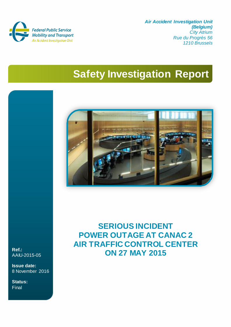
SERIOUS INCIDENT POWER OUTAGE AT CANAC 2
AIR TRAFFIC CONTROL CENTER ON 27 MAY 2015
AIRCRAFT TYPE
AT LOCATION ON XX MONTH 20XX
Safety Investigation Report
Ref.:
AAIU-2015-05 Issue date:
8 November 2016 Status:
Final

AAIU-2015-05
Fin
al r
ep
ort
2/40
1
THIS PAGE IS INTENTIONALLY LEFT BLANK
RefAAIU-2015-8
Issue date:
xx Month 20xx Status:
Final - draft
AAIU-2015-05
Fin
al r
ep
ort T
AB
LE
OF
CO
NT
EN
TS
3/40
TABLE OF CONTENTS
2
1 2
TABLE OF CONTENTS ................................................................................................................. 3
FOREWORD ................................................................................................................................... 4
SYMBOLS AND ABBREVIATIONS .............................................................................................. 5
TERMINOLOGY USED IN THIS REPORT .................................................................................... 6
SYNOPSIS 7
1 FACTUAL INFORMATION. ...................................................................................... 8
1.1 HISTORY OF THE EVENT. .............................................................................................. 8 1.2 INJURIES TO PERSONS. .............................................................................................. 11 1.3 DAMAGE TO AIRCRAFT. .............................................................................................. 11 1.4 OTHER DAMAGE......................................................................................................... 12 1.5 PERSONNEL INFORMATION ......................................................................................... 12 1.6 AIRCRAFT INFORMATION. ........................................................................................... 12 1.7 METEOROLOGICAL CONDITIONS. ................................................................................ 13 1.8 AIDS TO NAVIGATION .................................................................................................. 14 1.9 COMMUNICATION. ...................................................................................................... 19 1.10 AERODROME INFORMATION........................................................................................ 19 1.11 FLIGHT RECORDERS................................................................................................... 19 1.12 WRECKAGE AND IMPACT INFORMATION. ..................................................................... 19 1.13 MEDICAL AND PATHOLOGICAL INFORMATION............................................................... 19 1.14 FIRE. ......................................................................................................................... 20 1.15 SURVIVAL ASPECTS. .................................................................................................. 20 1.16 TESTS AND RESEARCH. .............................................................................................. 20 1.17 ORGANISATION AND MANAGEMENT INFORMATION. ..................................................... 21 1.18 ADDITIONAL INFORMATION. ........................................................................................ 23
2 ANALYSIS. .............................................................................................................. 24
2.1 THE FAILURE.............................................................................................................. 24 2.2 SERIOUS INCIDENT .................................................................................................... 26 2.3 ORIGIN OF THE PROBLEM. .......................................................................................... 27
3 CONCLUSIONS. ..................................................................................................... 30
3.1 CAUSES. .................................................................................................................... 30
4 SAFETY ACTIONS AND RECOMMENDATIONS. ................................................ 31
4.1 SAFETY ISSUE: CONTINGENCY PLANS ........................................................................ 31 4.2 SAFETY ISSUE: POWER SUPPLY ................................................................................. 31 4.3 SAFETY ISSUE: BUILD SPECIFICATIONS ...................................................................... 32
5 APPENDICES .......................................................................................................... 33
5.1 ELECTRICAL DRAWINGS. ............................................................................................ 33 5.2 EASA LETTER TO NSA .............................................................................................. 36
AAIU-2015-05
Fin
al r
ep
ort
FO
RE
WO
RD
4/40
FOREWORD This report is a technical document that reflects the views of the investigation team on the circumstances that led to the accident. In accordance with Annex 13 of the Convention on International Civil Aviation and EU Regulation 996/2010, it is not the purpose of aircraft accident investigation to apportion blame or liability. The sole objective of the investigation and the Final Report is the determination of the causes, and to define recommendations in order to prevent future accidents and incidents. In particular, Article 17-3 of the EU regulation EU 996/2010 stipulates that the safety recommendations made in this report do not constitute any suspicion of guilt or responsibility in the accident. The investigation was conducted by the AAIU(Be) with the support of Belgocontrol The report was prepared by Luc Blendeman.
Note:
About the time: For the purpose of this report, time will be indicated in UTC, unless
otherwise specified.
AAIU-2015-05
Fin
al r
ep
ort S
YM
BO
LS
AN
D A
BB
RE
VIA
TIO
NS
5/40
SYMBOLS AND ABBREVIATIONS ’ Minute °C Degrees centigrade AAIU(Be) Air Accident Investigation Unit (Belgium) ACC Area Control Center AcRep Accredited Representative of a State Investigation Unit AMSL Above Mean Sea Level ANS Air Navigation System APP Approach ATC Air Traffic Control ATCO Air Traffic Controller BCAA Belgian Civil Aviation Authority BRU FIR Brussels Flight Information Region CANAC Computer Assisted National Air Traffic Control Center CAVOK Ceiling and Visibility OK CMS Central Monitoring System CPL(H) Commercial Pilot Licence helicopter CSCI Computer Software Configuration Item. E East EBAW Antwerp Airport EBCI Charleroi AIrport EBBR Brussels Airport EBLG Liege Airport EBOS Ostend Airport EASA European Aviation Safety Agency EU European Union FAA Federal Aviation Administration (USA) FFS Fallback Flight Plan System (AS-Eurocat CSCI) ft Foot (Feet) GPS Global Positioning System HT High voltage Hz Hertz IT Isolated (unearthed) Neutral connection (in electrical systems) LH Left hand LRS Last Resort (Radio) System LSV Local System Supervision m Metre(s) MFS Main Flight Plan System (AS-Eurocat CSCI) N North OPS Operational (room) QNH Pressure setting to indicate elevation above mean sea level RH Right hand RWY Runway SN Serial Number TN Neutral connected to Earth (electrical system). TN-S Neutral connected to Earth (electrical system)with separated Neutral and Earth wire. UPS Uninterruptible Power Supply UTC Universal Time Coordinated VCS Voice Communication System VFR Visual Flight Rules
AAIU-2015-05
Fin
al r
ep
ort
TE
RM
INO
LO
GY
US
ED
IN T
HIS
RE
PO
RT
6/40
TERMINOLOGY USED IN THIS REPORT
Safety factor: an event or condition that increases safety risk. In other words, it is something that,
if it occurred in the future, would increase the likelihood of an occurrence, and/or the severity of the adverse consequences associated with an occurrence. Contributing safety factor: a safety factor that, had it not occurred or existed at the time of an
occurrence, then either: (a) the occurrence would probably not have occurred; or (b) the adverse consequences associated with the occurrence would probably not have occurred or have been as serious, or (c) another contributing safety factor would probably not have occurred or existed. Other safety factor: a safety factor identified during an occurrence investigation which did not
meet the definition of contributing safety factor but was still considered to be important to communicate in an investigation report in the interests of improved transport safety. Safety issue: a safety factor that
(a) can reasonably be regarded as having the potential to adversely affect the safety of future operations, and (b) is a characteristic of an organisation or a system, rather than a characteristic of a specific individual, or characteristic of an operational environment at a specific point in time. Safety action: the steps taken or proposed to be taken by a person, organisation or agency on its
own initiative in response to a safety issue. Safety recommendation: A proposal by the accident investigation authority in response to a safety
issue and based on information derived from the investigation, made with the intention of preventing accidents or incidents. When AAIU(Be) issues a safety recommendation to a person, organization, agency or Regulatory Authority, the person, organization, agency or Regulatory Authority concerned must provide a written response within 90 days. That response must indicate whether the recommendation is accepted, or must state any reasons for not accepting part or all of the recommendation, and must detail any proposed safety action to bring the recommendation into effect. Safety message: An awareness which brings to attention the existence of a safety factor and the
lessons learned. AAIU(Be) can distribute a safety message to a community (of pilots, instructors, examiners, ATC officers), an organization or an industry sector for it to consider a safety factor and take action where it believes it appropriate. There is no requirement for a formal response to a safety message, although AAIU(Be) will publish any response it receives.
AAIU-2015-05
Fin
al r
ep
ort S
YN
OP
SIS
7/40
SYNOPSIS
Date and time: 27 May 2015 at 07.15 UTC
Aircraft: Various, 28 aircraft under Belgocontrol ATC supervision in the
Brussels FIR/UIR below FL245 Occurrence location: Belgocontrol facility, Steenokkerzeel Type of incident: Loss of Air Traffic Control Services Injuries: none Abstract:
At 07:15 on Wednesday 27 May 2015, further to the verification of the standby diesel-powered generators, the electrical power generation system suffered a major disruption. Electrical power to the Air Traffic Control (ATC) CANAC surveillance room of Belgocontrol, managing the en-route and approach traffic in the Brussels FIR, was interrupted. This had for consequence that the radar imagery and radio contact between ATC and the aircraft in flight was interrupted. The ATC services at all Belgian airport towers (EBBR, EBAW, EBCI, EBLG, EBOS) were not affected, and towers retained their whole supervision capability. After the first moment of surprise, CANAC ATCOs applied an emergency ‘clear the sky’ procedure using the Last Resort radio System (a set of frequencies for ACC and APP; amongst others the emergency frequency 121.5MHz), leading to the landing of inbound flights, transferring the control to the towers, the military ATC or neighbouring ATC unit. At 07:30, all aircraft were safely on the ground, or were leaving the BRU FIR, under positive ATC control. Cause
The ANS disruption was caused by an electrical power failure during a routine check of the standby diesel powered generators. This failure was caused by a cascade of events, starting by a defect in an electrical motor of an industrial air conditioning unit, causing an important unbalance in the power distribution network due to the absence of earthing of the neutral wire of the diesel-powered generators and resulting in the failure by overvoltage of vital equipment in the ATC control room. Contributing safety factors:
Belgocontrol’s contingency plan did not foresee a scenario involving a total electrical failure.
AAIU-2015-05
Fin
al r
ep
ort
Fa
ctu
al in
form
atio
n.
8/40
1 Factual information.
1.1 History of the event.
At 07:15 on Wednesday 27 May 2015, further to the verification of the diesel-powered emergency generators, the electrical network of Belgocontrol suffered a major disruption. The check was performed at the end of the morning traffic peak. The check consists of simulating the failure of the normal power distribution by opening the main switches. The immediate power loss is compensated by batteries (no-break system with a maximum autonomy of 20 minutes – Uninterruptible Power Supply UPS System). The further emergency sequence is fully automatic; the power loss is sensed by the system, power to non-essential systems (such as refrigerating units of the air-conditioning system) is interrupted, and after 4 seconds, all 3 standby diesel powered generators are started. During the starting sequence, the standby generators remain disconnected from the network. The initial sequence lasted 20 seconds, during which all 3 generators are synchronised. When the emergency electrical power generation is stable and synchronised, the system connects the generators to the network. All this happened flawlessly on the day of the incident. After a short delay, a major disruption occurred, precisely when non-essential systems were reconnected to the network. Electrical power to the ATC CANAC surveillance room, managing the en-route and approach traffic in the Brussels FIR, was interrupted. This had for consequence that all main radar display, backup radar display (both on a single display) and main voice communication system (radio contact between ATC and the aircraft in flight) went instantly offline. The only equipment remaining available was the Last Resort (Radio) System (a set of frequencies for ACC and APP, amongst others, the aircraft emergency frequency 121.5MHz).
The ATC services at the airport towers (EBBR, EBAW, EBCI, EBLG, EBOS) remain operational and towers retained their whole supervision capability. The en-route and approach Air Traffic Controllers realised the situation and, using all available means including personal mobile phones, contacted the neighbouring centers (MUAC, Towers, Military ATC) Communication with the airplanes they had under control, was re-established using the Last Resort radio system leading to the landing of inbound flights, transferring the control to the towers, the military ATC or neighbouring ATC unit (clear the sky procedure). A free available website for live flight tracking, based on Automatic Dependent Surveillance Broadcast (ADS-B) and Mode S MLAT was also used to some extent.
Out of the 28 flights under control at the moment of the outage, 18 were back under positive control at 07:18 and an additional 5 about one minute later. At 07:30 all traffic in the Brussels FIR was under positive radar control.
The next process was to ensure the continuing safety of all the flights above Belgium, by either:
Conducting the flights to other sectors (France, UK, The Netherlands,..)
AAIU-2015-05
Fin
al r
ep
ort F
actu
al in
form
atio
n.
9/40
Instructing the airplanes to land under the control of the local towers.
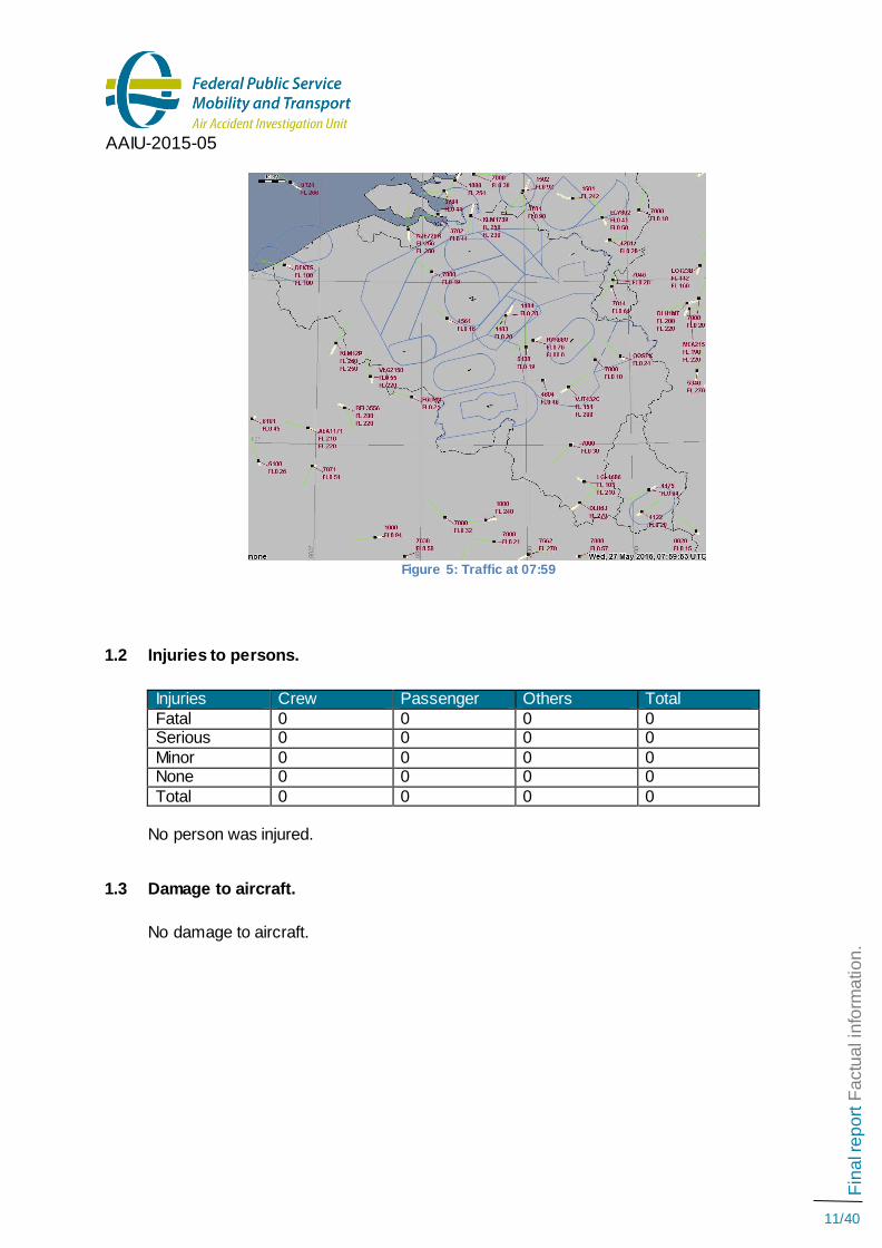
At 07:46, the last commercial flight landed safely in the Brussels FIR. At 07:59, all aircraft were safely on the ground or were leaving the BRU FIR, under control. At no time loss of separation between aircraft did occur. Contacts with MUAC and the other centres ensured diversion to all inbound flights. The first NOTAM indicating the ATC failure was issued at 09:06.
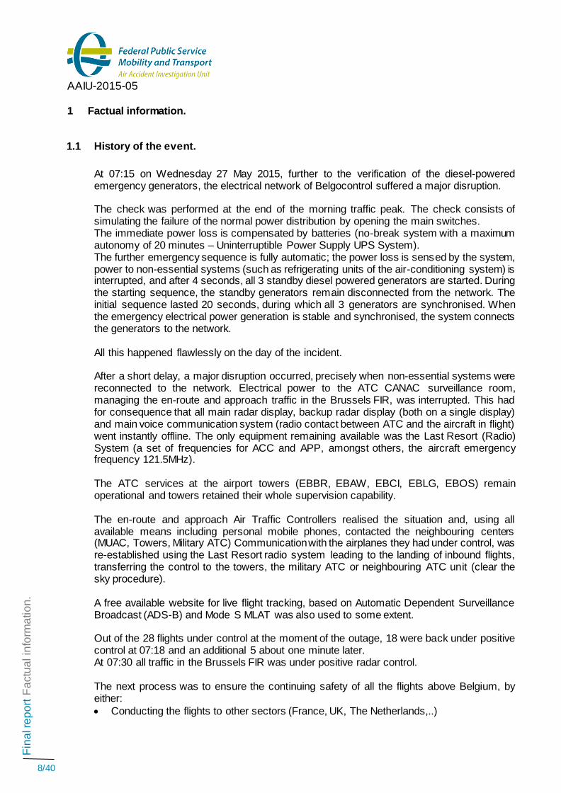
Figure 1: extract of the European FIR/UIR chart showing the boundaries of the Brussels FIR
Figure 2: Traffic at 07:15
AAIU-2015-05
Fin
al r
ep
ort
Fa
ctu
al in
form
atio
n.
10/40
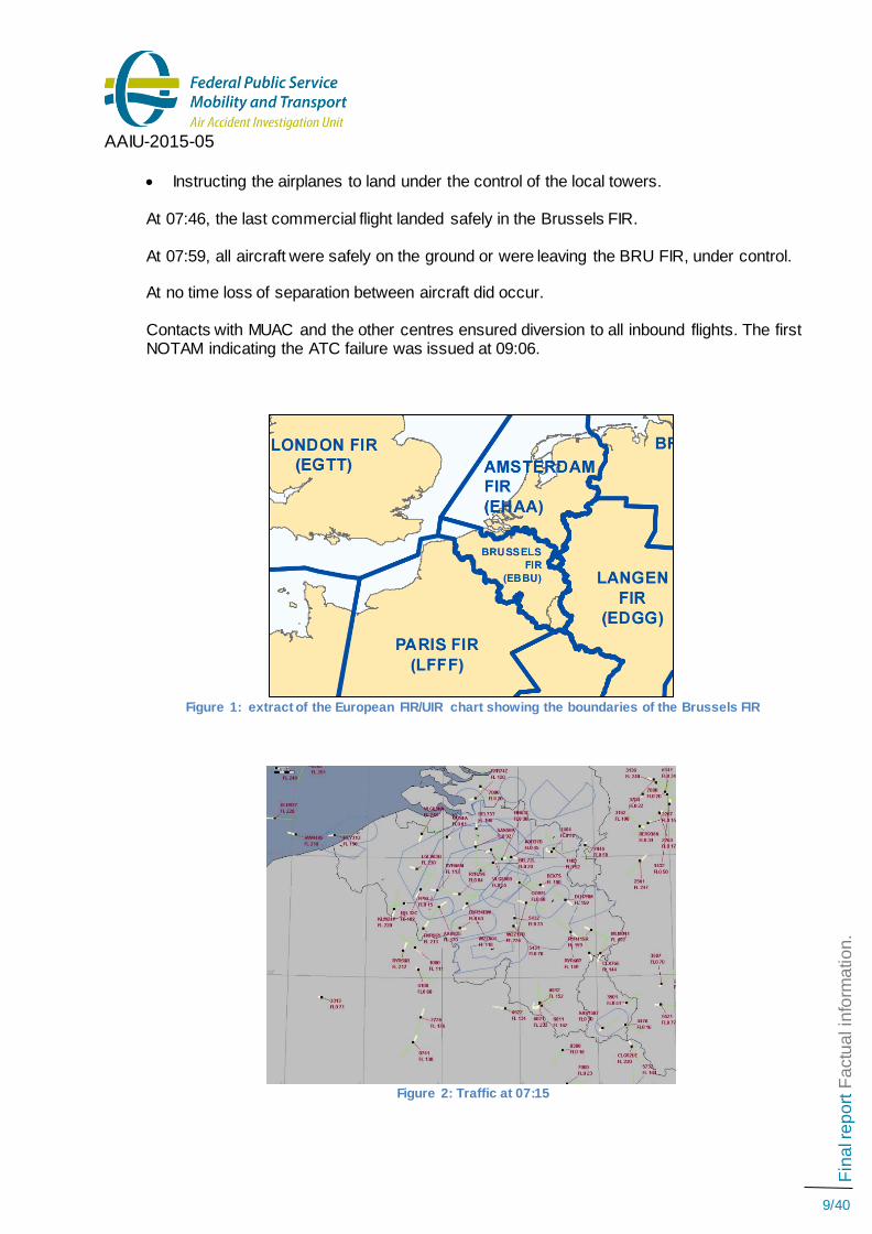
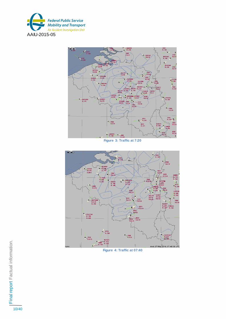
Figure 3: Traffic at 7:20
Figure 4: Traffic at 07:40
AAIU-2015-05
Fin
al r
ep
ort F
actu
al in
form
atio
n.
11/40
Figure 5: Traffic at 07:59
1.2 Injuries to persons.
Injuries Crew Passenger Others Total
Fatal 0 0 0 0 Serious 0 0 0 0
Minor 0 0 0 0 None 0 0 0 0
Total 0 0 0 0
No person was injured.
1.3 Damage to aircraft.
No damage to aircraft.
AAIU-2015-05
Fin
al r
ep
ort
Fa
ctu
al in
form
atio
n.
12/40
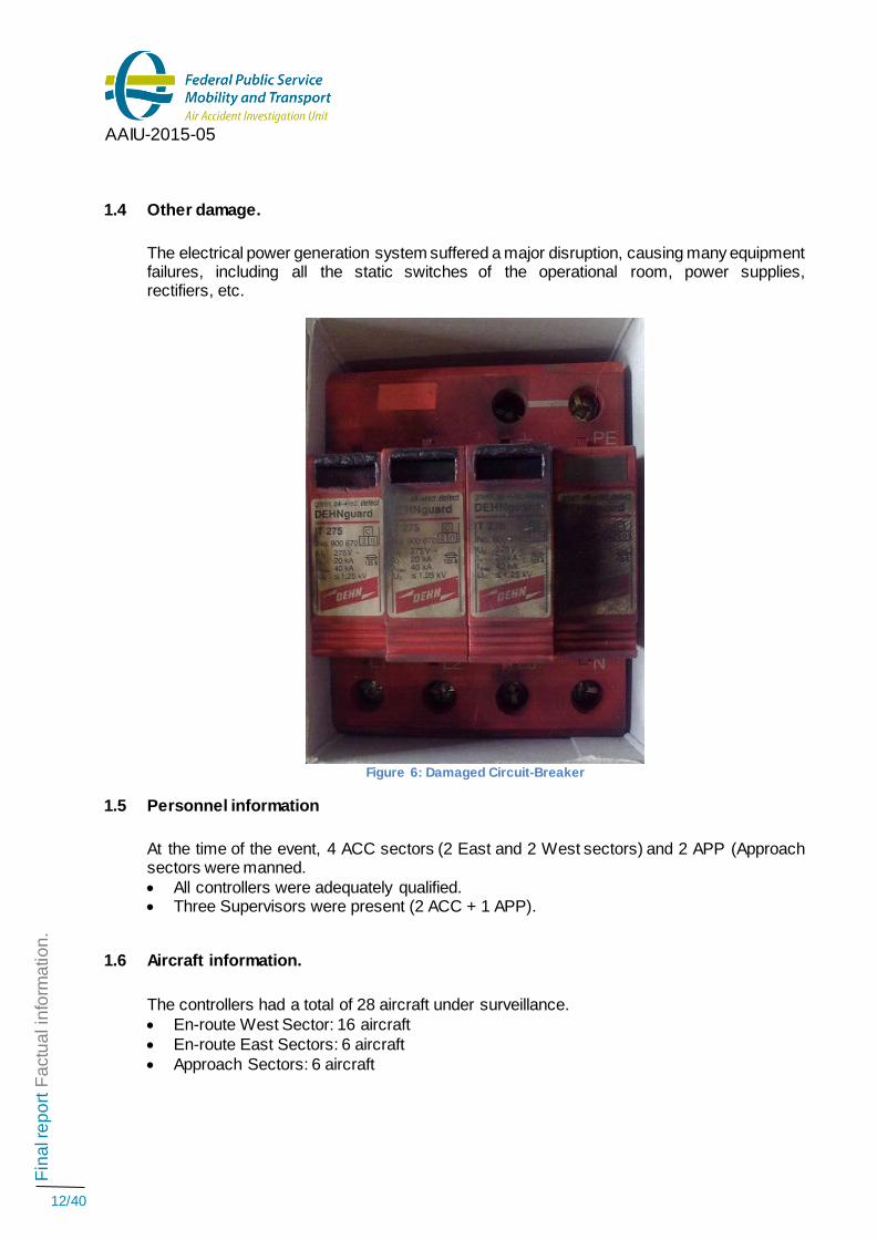
1.4 Other damage.
The electrical power generation system suffered a major disruption, causing many equipment failures, including all the static switches of the operational room, power supplies, rectifiers, etc.
Figure 6: Damaged Circuit-Breaker
1.5 Personnel information
At the time of the event, 4 ACC sectors (2 East and 2 West sectors) and 2 APP (Approach sectors were manned.
All controllers were adequately qualified. Three Supervisors were present (2 ACC + 1 APP).
1.6 Aircraft information.
The controllers had a total of 28 aircraft under surveillance.
En-route West Sector: 16 aircraft
En-route East Sectors: 6 aircraft
Approach Sectors: 6 aircraft
AAIU-2015-05
Fin
al r
ep
ort F
actu
al in
form
atio
n.
13/40
1.7 Meteorological conditions.
GAMET
GAMET EBBU FABX31 EBBR 270242 EBBU GAMET VALID 270600/271200 EBBR- EBBU BRUSSELS FIR BLW FL100 SECN I HAZARDOUS WX NIL SECN II PSYS: 06. H1037 HPA N OF THE AZORES WITH RIDGE EXTENDING TOWARDS FRANCE. MARITIME NNW’LY FLOW, SLIGHTLY UNSTABLE AIR ADVECTED OVER EBBU. A DISSOLVING OCCLUSION MOVING OVER THE COUNTRY. SFC WSPD (<=30kt°: 06-09KT WIND/T: 1000FT 270/10KT. E VRB/05KT.PS10 2000 FT 270/10KT. E VRB/05KT. PS06 5000 FT 260/10KT. MS00 10000 FT 340/15KT. MS03 SFC VIS (>5KM)/ 10 KM CLD: SCT-BKN CU SC 3000/6000FT AGL FZLVL: 6000 FT AGL MNM QNH: 1024 HPA OTLK: FM 12 TL 18 Z HAZARDOUS WX NIL
The conditions in Brussels airport were:
27/05/2015 07:20:31, WIND: 25L 210 02KT VRB BTN 130 AND 290 WIND: 25R 200 04KT MAX 09 MNM 02 VRB BTN 120 AND 220 WIND: 01 190 05KT VRB BTN 110 AND 230 WIND: 07L VRB 02KT VIS: CAVOK T: 13 DP: 05 MET QFE: 1018.9HPA QNH: 1025.6HPA WS: RE: TREND: NOSIG RH: 57 TXT:
27/05/2015 07:36:00, WIND: 25L VRB 01KT WIND: 25R 180 03KT VRB BTN 090 AND 240 WIND: 01 VRB 03KT WIND: 07L 170 01KT VRB BTN 090 AND 260 VIS: CAVOK T: 15 DP: 06 MET QFE: 1018.9HPA QNH: 1025.5HPA WS: RE: TREND: NOSIG RH: 55 TXT: 27/05/2015 07:50:28, WIND: 25L CALM WIND: 25R VRB 01KT WIND: 01 200 03KT VRB BTN 170 AND 270 WIND: 07L VRB 03KT VIS: CAVOK T: 15 DP: 06 MET QFE: 1018.9HPA QNH: 1025.5HPA WS: RE: TREND: NOSIG RH: 57 TXT:
AAIU-2015-05
Fin
al r
ep
ort
Fa
ctu
al in
form
atio
n.
14/40
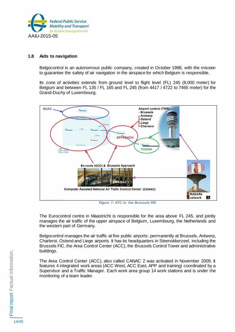
1.8 Aids to navigation
Belgocontrol is an autonomous public company, created in October 1998, with the mission to guarantee the safety of air navigation in the airspace for which Belgium is responsible. Its zone of activities extends from ground level to flight level (FL) 245 (8,000 meter) for Belgium and between FL 135 / FL 165 and FL 245 (from 4417 / 4722 to 7465 meter) for the Grand-Duchy of Luxembourg.
Figure 7: ATC in the Brussels FIR
The Eurocontrol centre in Maastricht is responsible for the area above FL 245, and jointly manages the air traffic of the upper airspace of Belgium, Luxembourg, the Netherlands and the western part of Germany. Belgocontrol manages the air traffic at five public airports: permanently at Brussels, Antwerp, Charleroi, Ostend and Liege airports. It has its headquarters in Steenokkerzeel, including the Brussels FIC, the Area Control Center (ACC), the Brussels Control Tower and administrative buildings. The Area Control Center (ACC), also called CANAC 2 was activated in November 2009. It features 4 integrated work areas (ACC West, ACC East, APP and training) coordinated by a Supervisor and a Traffic Manager. Each work area group 14 work stations and is under the monitoring of a team leader.

AAIU-2015-05
Fin
al r
ep
ort F
actu
al in
form
atio
n.
15/40
Figure 8: CANAC 2 Work area
Each work station provides a Traffic controller with a computerized radar imagery and communication.
Figure 9: ATC System
AAIU-2015-05
Fin
al r
ep
ort
Fa
ctu
al in
form
atio
n.
16/40
The ATC system is designed in 3 modes providing assurance that the controller continues to be able to control the air traffic:
The nominal mode; the ATC controller receives; Radio communication with aircraft
Integrated information regarding the flight plans
Integrated information from a network of radars
Integrated information regarding the meteorological conditions, etc
The “fallback” mode. The ATC controller receives the same information as in the nominal
mode, but the information is conveyed through alternate channels, automatically
triggered.
Should the nominal and fallback system fail, the ATC controller still receives essential
data, conveyed by a totally independent network.
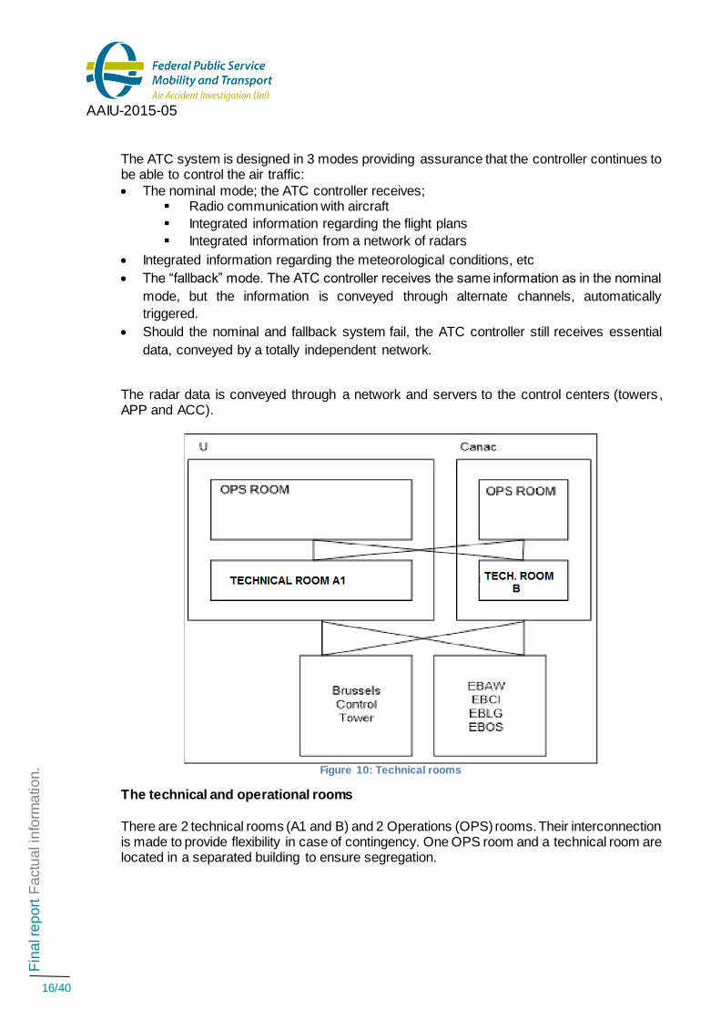
The radar data is conveyed through a network and servers to the control centers (towers, APP and ACC).
Figure 10: Technical rooms
The technical and operational rooms
There are 2 technical rooms (A1 and B) and 2 Operations (OPS) rooms. Their interconnection is made to provide flexibility in case of contingency. One OPS room and a technical room are located in a separated building to ensure segregation.
AAIU-2015-05
Fin
al r
ep
ort F
actu
al in
form
atio
n.
17/40
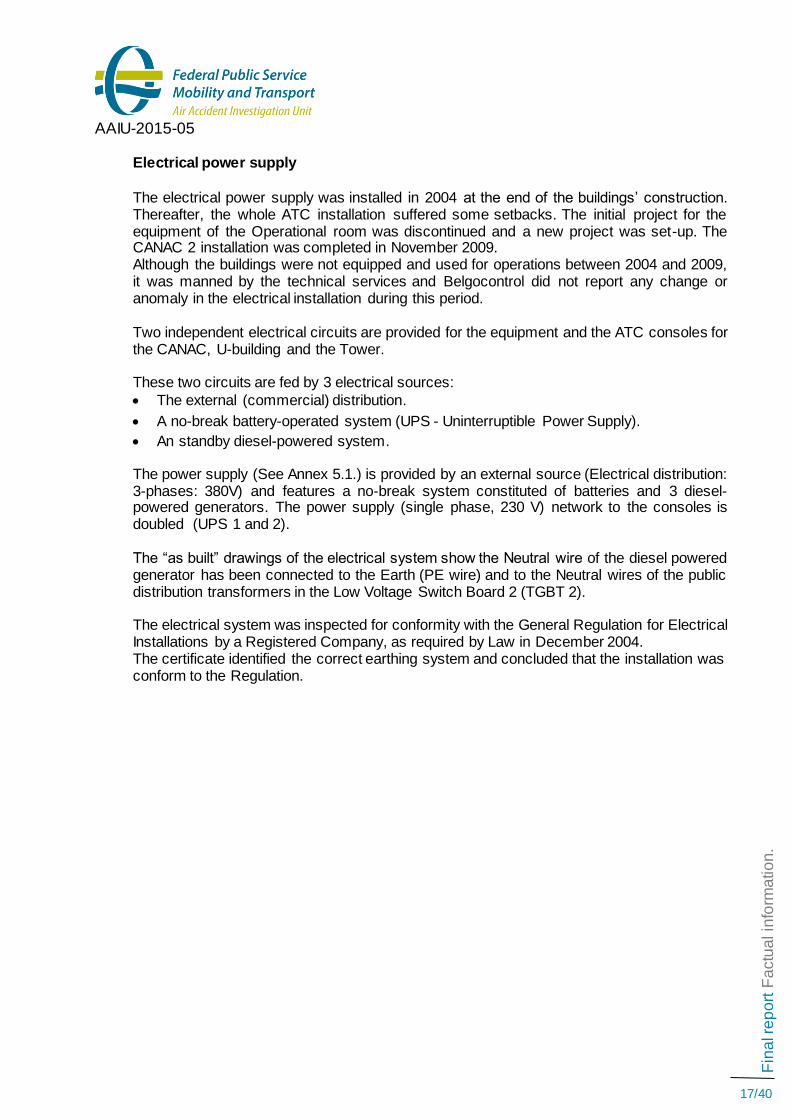
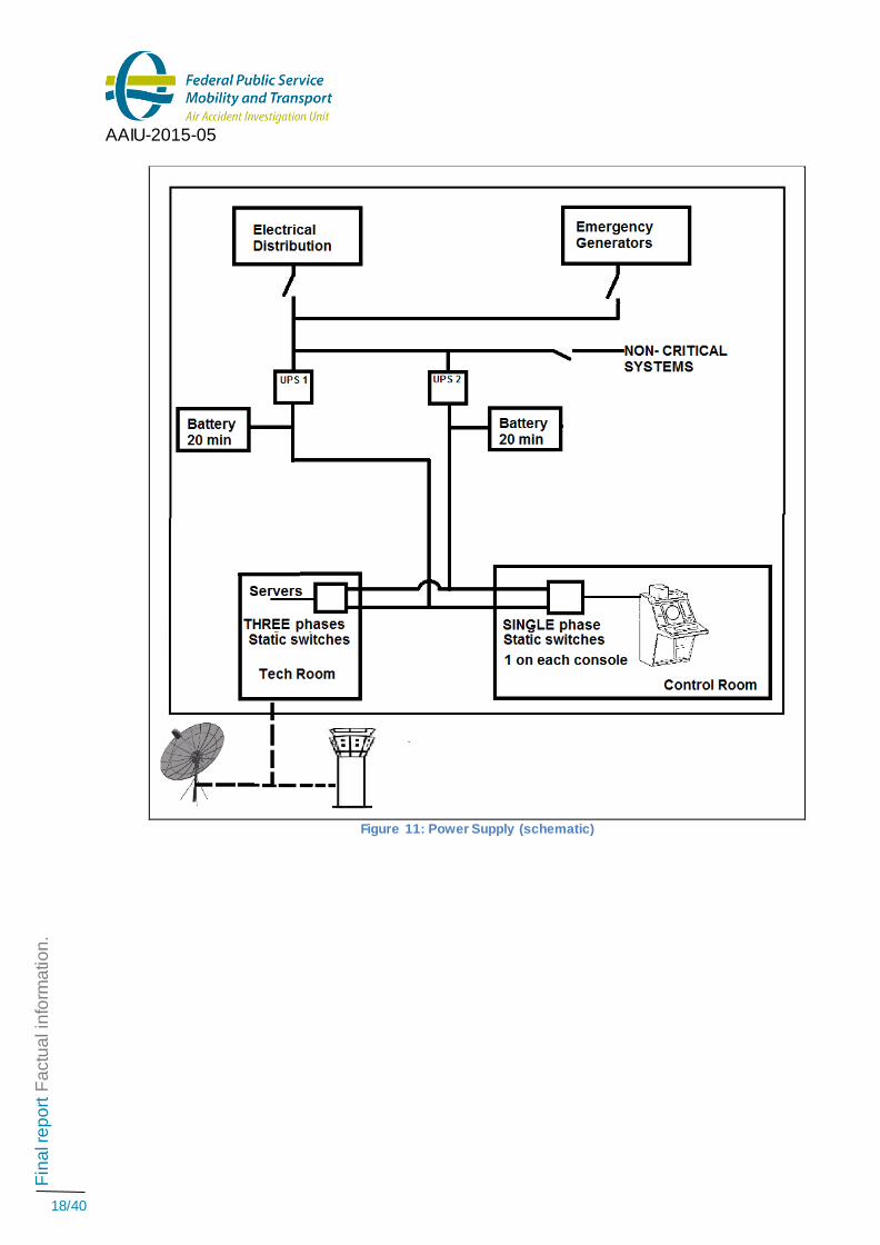
Electrical power supply
The electrical power supply was installed in 2004 at the end of the buildings’ construction. Thereafter, the whole ATC installation suffered some setbacks. The initial project for the equipment of the Operational room was discontinued and a new project was set-up. The CANAC 2 installation was completed in November 2009. Although the buildings were not equipped and used for operations between 2004 and 2009, it was manned by the technical services and Belgocontrol did not report any change or anomaly in the electrical installation during this period. Two independent electrical circuits are provided for the equipment and the ATC consoles for the CANAC, U-building and the Tower. These two circuits are fed by 3 electrical sources:
The external (commercial) distribution.
A no-break battery-operated system (UPS - Uninterruptible Power Supply).
An standby diesel-powered system.
The power supply (See Annex 5.1.) is provided by an external source (Electrical distribution: 3-phases: 380V) and features a no-break system constituted of batteries and 3 diesel-powered generators. The power supply (single phase, 230 V) network to the consoles is doubled (UPS 1 and 2). The “as built” drawings of the electrical system show the Neutral wire of the diesel powered generator has been connected to the Earth (PE wire) and to the Neutral wires of the public distribution transformers in the Low Voltage Switch Board 2 (TGBT 2). The electrical system was inspected for conformity with the General Regulation for Electrical Installations by a Registered Company, as required by Law in December 2004. The certificate identified the correct earthing system and concluded that the installation was conform to the Regulation.
AAIU-2015-05
Fin
al r
ep
ort
Fa
ctu
al in
form
atio
n.
18/40
Figure 11: Power Supply (schematic)
AAIU-2015-05
Fin
al r
ep
ort F
actu
al in
form
atio
n.
19/40
Test of the emergency power system.
Prior to 27 May 2015, the diesel-powered electrical generation system was checked in:
29 April 2015.
26 November 2014.
29 October 2014.
No check were performed between November 2014 and April 2015 owing to the need to replace some batteries of the UPS system. The batteries were replaced in March 2015 and the verification resumed in April 2015.
1.9 Communication.
The main voice communication system of the Operational Room was connected to a dedicated and specific UPS power supply through a Static switch before being distributed in each console. When this Static switch failed, the operating panels were no longer powered and the main voice communication system was interrupted. The configuration of the communication system, being modified in the past, caused limited disruption in the use of the Last Resort System and the in use of the emergency cordless telephones. However, the Last Resort System, which is a set of frequencies for ACC and APP, including amongst others the emergency radio frequency on 121.5MHz was still usable because it is powered by an independent power supply circuit. It was put to good use by the ATCOs retaining some communication with the aircrafts. ATCOs used their personal mobile phones to get contact with the Control Towers. NOTAMs: A first NOTAM was issued on 09:08 : “Brussels ACC CLSD due to technical
failure”.
1.10 Aerodrome information.
Not applicable
1.11 Flight recorders.
All radar data and communication are recorded and were available for the investigation.
1.12 Wreckage and impact information.
Not Applicable
1.13 Medical and pathological information.
Not Applicable
AAIU-2015-05
Fin
al r
ep
ort
Fa
ctu
al in
form
atio
n.
20/40
1.14 Fire.
Not Applicable
1.15 Survival aspects.
Not Applicable
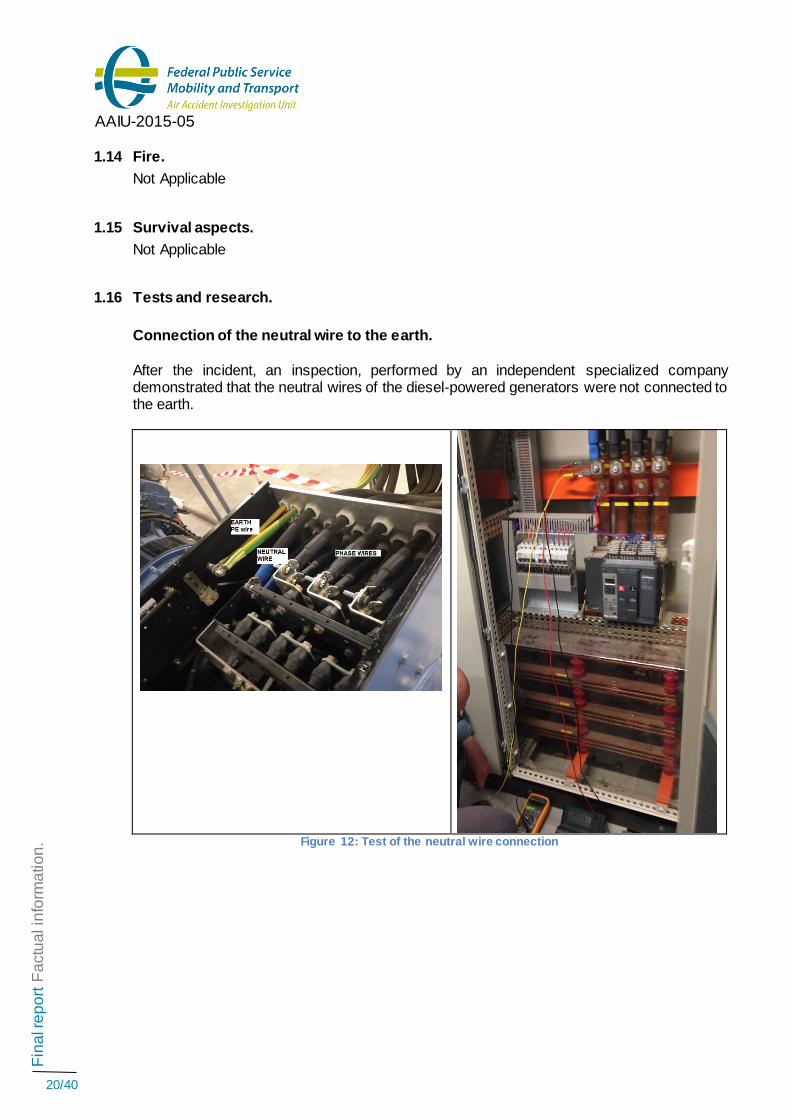
1.16 Tests and research.
Connection of the neutral wire to the earth.
After the incident, an inspection, performed by an independent specialized company demonstrated that the neutral wires of the diesel-powered generators were not connected to the earth.
Figure 12: Test of the neutral wire connection
AAIU-2015-05
Fin
al r
ep
ort F
actu
al in
form
atio
n.
21/40
Belgocontrol investigation
Belgocontrol conducted its own investigation on the incident. A dedicated team of investigators issued an extensive report in December 2015. Assistance was provided by Prof. Chris Johnson, DPhil, MSc, MA, FBCS, CEng, CITP, Professor at the Glasgow University. His assistance allowed to gain his expertise on the subject as well as experience from previous similar incidents, such as the NATS system failure in the UK on 12 December 2014. The Final Investigation Report issued by Belgocontrol on this occurrence, covered the operational and technical aspects of the event. 84 internal recommendations were raised aimed at improving the resilience of the whole system. A separate investigation on the technical aspects of the event was conducted investigated by two specialised firms, Laborelec and DNV-GL upon request of Belgocontrol.
Belgocontrol initiated also a series of initiatives aimed at gathering all possible lessons to be learned by this incident.
1.17 Organisation and Management Information.
The design and construction of a building such as CANAC occurs with the definition of build specifications (Cahier de charges / Lastenboek) stating Belgocontrol’s requirements on all aspects of the work. This build specification is submitted to a public bidding. The Company (usually an association of several specialized companies) providing the best bid gets the contract. The build specifications requirements are further used during construction to assess the works, up to the final reception of the works. The build specifications themselves are usually also prepared through a public bidding. In the case of CANAC, the Engineering office dealing with the build specifications was an association of 3 architects and engineering offices. Belgocontrol provided AAIU(Be) the following documents, pertaining to the electrical system:
Cahier des charges n°2003-04-28 Fascicule A : Clauses Administratives
Cahier Special des charges N°018 – Electricité – Clauses techniques
Cahier des charges – type 400 – Electricité en général
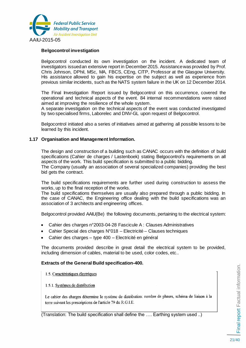
The documents provided describe in great detail the electrical system to be provided, including dimension of cables, material to be used, color codes, etc.. Extracts of the General Build specification-400.
(Translation: The build specification shall define the …. Earthing system used ..)
AAIU-2015-05
Fin
al r
ep
ort
Fa
ctu
al in
form
atio
n.
22/40
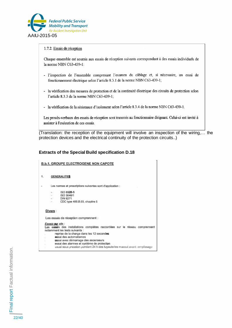
(Translation: the reception of the equipment will involve an inspection of the wiring,… the protection devices and the electrical continuity of the protection circuits..) Extracts of the Special Build specification D.18
AAIU-2015-05
Fin
al r
ep
ort F
actu
al in
form
atio
n.
23/40
1.18 Additional information.
Other events During the period between 27th May 2015 and 27th May 2016, there were several other ATC disruptions encountered. The cause of these disruptions were different, and of a lesser magnitude, than the one of the 27th May. The other events included;
On 16 February 2016, total loss of radar imagery (Main, backup and ultimate) at the
CANAC ATC center and related regional airports during 30 seconds, between 08:29:38
and 08:30:10. The event took place during a routine maintenance of a regional radar,
further to a faulty manipulation by a technician.
On 2 April 2016, loss of the Flight Data Processing capability for 55 minutes between
12.48 and 13.43. Radar imagery and radio communication were not impaired, but ATC
controllers had no longer access to the flight plan data. Traffic restriction procedures were
applied.
The event was investigated by Belgocontrol’s Safety Management Unit; a latent software
“bug” was found to be the cause of the disruption.
AAIU-2015-05
Fin
al r
ep
ort
An
aly
sis
.
24/40
2 Analysis.
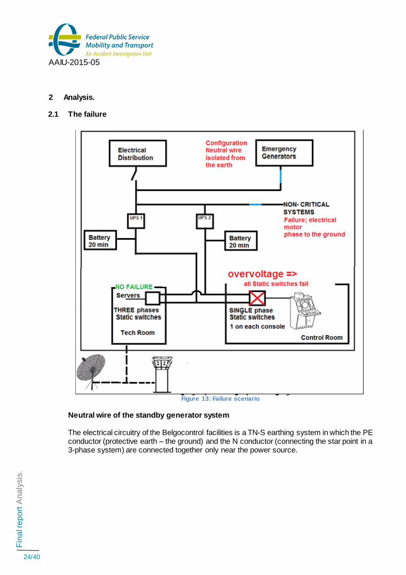
2.1 The failure
Figure 13: Failure scenario
Neutral wire of the standby generator system
The electrical circuitry of the Belgocontrol facilities is a TN-S earthing system in which the PE conductor (protective earth – the ground) and the N conductor (connecting the star point in a 3-phase system) are connected together only near the power source.
AAIU-2015-05
Fin
al r
ep
ort A
na
lysis
.
25/40
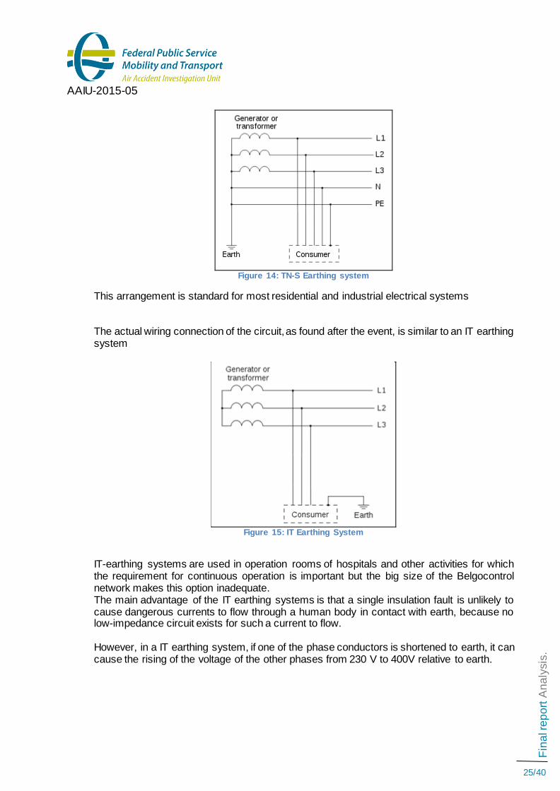
Figure 14: TN-S Earthing system
This arrangement is standard for most residential and industrial electrical systems
The actual wiring connection of the circuit, as found after the event, is similar to an IT earthing system
Figure 15: IT Earthing System
IT-earthing systems are used in operation rooms of hospitals and other activities for which the requirement for continuous operation is important but the big size of the Belgocontrol network makes this option inadequate. The main advantage of the IT earthing systems is that a single insulation fault is unlikely to cause dangerous currents to flow through a human body in contact with earth, because no low-impedance circuit exists for such a current to flow. However, in a IT earthing system, if one of the phase conductors is shortened to earth, it can cause the rising of the voltage of the other phases from 230 V to 400V relative to earth.
AAIU-2015-05
Fin
al r
ep
ort
An
aly
sis
.
26/40
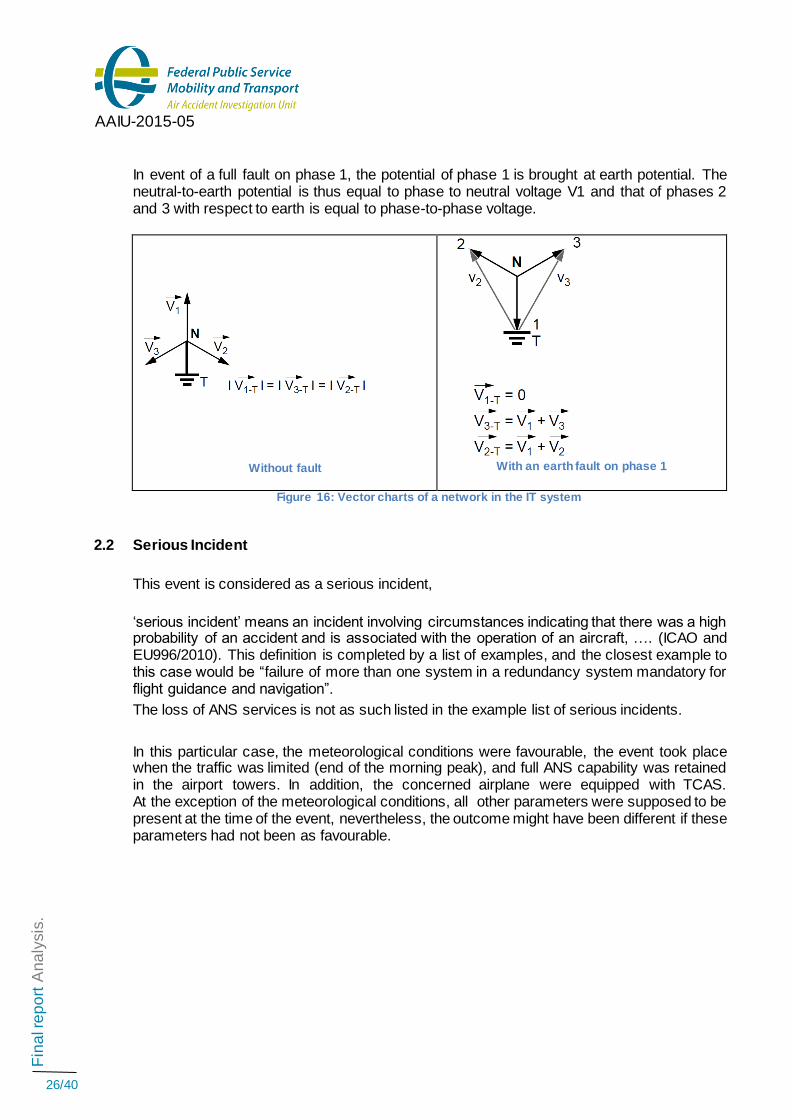
In event of a full fault on phase 1, the potential of phase 1 is brought at earth potential. The neutral-to-earth potential is thus equal to phase to neutral voltage V1 and that of phases 2 and 3 with respect to earth is equal to phase-to-phase voltage.
Without fault
With an earth fault on phase 1
Figure 16: Vector charts of a network in the IT system
2.2 Serious Incident
This event is considered as a serious incident,
‘serious incident’ means an incident involving circumstances indicating that there was a high probability of an accident and is associated with the operation of an aircraft, …. (ICAO and EU996/2010). This definition is completed by a list of examples, and the closest example to this case would be “failure of more than one system in a redundancy system mandatory for flight guidance and navigation”.
The loss of ANS services is not as such listed in the example list of serious incidents.
In this particular case, the meteorological conditions were favourable, the event took place when the traffic was limited (end of the morning peak), and full ANS capability was retained in the airport towers. In addition, the concerned airplane were equipped with TCAS. At the exception of the meteorological conditions, all other parameters were supposed to be present at the time of the event, nevertheless, the outcome might have been different if these parameters had not been as favourable.
AAIU-2015-05
Fin
al r
ep
ort A
na
lysis
.
27/40
2.3 Origin of the problem.
The event had important consequences for two reasons:
A latent problem in the electrical system was present and not detected for a considerable
amount of time.
No contingency plan existed on the possibility of general loss of electrical power.
Latent problem.
The incident revealed a major flaw in the electrical system; the connection of the neutral wire of the emergency generators were not connected to the earth, as it should have been. The ‘as built’ electrical drawing shows the Neutral wire connected to the earth, witness that the requirement for the connection of the neutral wire was understood by the installer and believed to be performed. The inspection of the electrical installation does not show evident sign of modification of the electrical wiring. Evidence showed that Belgocontrol’s procedures require documentation to support modifications applied to the electrical system. It is also believed that the installation were adequately secured during the period 2005 – 2009, although not used for operations. The power supply installation was completed and certified in December 2004. The reception of the works and certification did not detect any anomaly. The power supply installation was only put in use in November 2009, when CANAC 2 was made operational. However, the building was manned since 2005 by the technical services. We could therefore conclude that it is highly probable that the non-connection of the Neutral wire to the earth existed since the construction of the electrical system of CANAC. Owing to the time past, it is impossible to determine the exact course of action that led to the omission. After this initial omission was made, the situation could only be detected by chance, as the
electrical circuit configuration is normally not questioned during maintenance or subsequent
modification and this configuration does not produce evident signs during use, which is limited
to the verification of the emergency system functioning (6 times during the previous year).
The build specifications (400 and D18) describe in general terms the inspection and tests to
perform during the reception of the work.
Several build specifications concerning the installation or modifications of electrical systems
for other State-owned buildings were analysed and some include a text requiring a specific
verification of the actual connection of the neutral wire as part of the reception process. This
kind of requirement was not found in the copies of the build specification documents provided
by Belgocontrol. It is believed that, had such specific requirement be present at the time, the
non-connection of the Neutral wire had better chances to be detected.
AAIU-2015-05
Fin
al r
ep
ort
An
aly
sis
.
28/40
Contingency plan
The absence of a contingency plan dealing with a total loss of power supply had for consequence that the traffic control personnel was caught off guard, totally unprepared for an event of this magnitude.
The risk of losing electrical power was considered an unacceptable risk. Therefore, the power
supply installation was designed in such a way that the risk of total loss of the electrical power
was considered negligible. For this reason, the contingency plan did not considered a
scenario of the magnitude of this event.
The disruptions that occurred in February and April 2016 (para. 1.8.) in addition to the major
event of 27 May 2015 show that in spite of all human efforts to produce a flawless system,
latent failures and problems may remain undetected in a system for a long period and may
activate unexpectedly.
The nature of the flaw may be either in design (Event of 16 February: The fact that a single
manipulation could cause a general disconnection of all radar data is considered a latent
design fault.) or in the realisation (the software bug of 2 April).
This statement does not imply that systems must not be designed to minimize disruptions, it
only implies that there is no such thing as a “perfect system” and, owing to the risks involved,
an adequate contingency plan must be in place.
Resiliency
The power loss did not cause any actual accident or even loss of separation, owing to the
remarkable reaction of the ATC Controllers. The Belgocontrol internal investigation report
covers in detail the event, describing the reaction of controllers, detailing the difficulties
encountered, but also the local solutions applied during the emergency (such as the use of
personal mobile phones and computers, the use – to some extent – of a flight tracking
website, for example). This is particularly interesting for the functioning of Belgocontrol,
identifying resiliency issues and bringing numerous lessons learned.
The report outlines the following operational success factors:
The outage happened after the morning peak (Note: as planned, ensuring availability of
personnel and low traffic activity).
All towers remained fully operational.
Air Traffic Controllers quickly understood the importance of the problem.
Air Traffic Controllers (ACC, APP, EBBR Tower and the regional towers) reacted promptly
by stopping departures, recalling departed traffic back or coordinating onward clearances,
using LRS, mobile phone, the emergency frequency,..)
MUAC was the first one to be alerted about the outage and it immediately notified all the
neighbouring centers
AAIU-2015-05
Fin
al r
ep
ort A
na
lysis
.
29/40
Very positive cooperation with the military Air Traffic Control.
The outage happened in VMC (Visual Meteorological Conditions)
The LRS was still (partly) available.
Some of the elements here-above are due to chance (meteorological conditions), but most are the result of the company’s safety culture and the quality of the ATCOs training and qualification. The same could be said for the engineering staff that took a series of short-term remedial action to reconfigure the electrical system in order to ensure a quick and safe recovery. The TCAS system was still available as an ultimate barrier. None activated.
AAIU-2015-05
Fin
al r
ep
ort
Co
nclu
sio
ns.
30/40
3 Conclusions.
3.1 Causes.
The ANS disruption was caused by an electrical power failure during a routine check of the standby diesel powered generators. This failure was caused by a cascade of events, starting by a defect in an electrical motor of an industrial air conditioning unit, causing an important unbalance in the power distribution network due to the absence of earthing of the neutral wire of the diesel-powered generators and resulting in the failure by overvoltage of vital equipment in the ATC control room.
Contributing safety factor: Belgocontrol’s contingency plan did not foresee a scenario involving a total electrical failure.
AAIU-2015-05
Fin
al r
ep
ort S
afe
ty a
ctio
ns a
nd
re
co
mm
en
da
tio
ns.
31/40
4 Safety actions and recommendations.
The following actions, among others, are already applied by Belgocontrol:
Implementing the necessary corrective actions to assess and repair the damage to the
electrical system,
Restoring the electrical system to an adequate configuration (including the review of the
electrical system in other buildings of Belgocontrol, such as the control towers),
Reviewing the electrical distribution system and apply the necessary corrections
(emergency generators with neutral wire to the earth).
Reviewing the electrical power distribution to the radar consoles of CANAC 2 in order to
improve the protection in case of overload.
Providing the CANAC 2 surveillance room with displays showing radar imagery
connected to an independent power source.
AAIU(Be) encourages Belgocontrol to implement all the recommendations made by their Safety Management Unit in their investigation report ref. SROEQ15-088 in particular the continuing efforts to identify all single points of failure and to eliminate them or mitigate their possible effects.
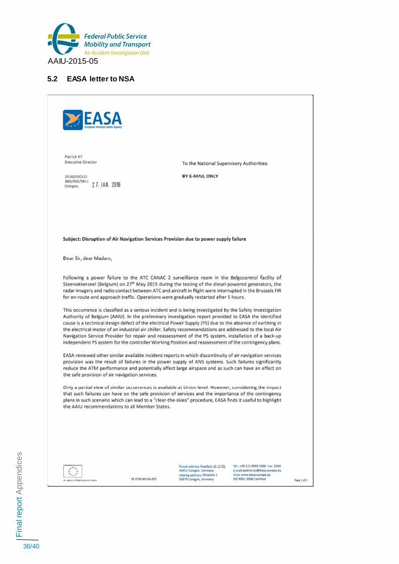
Two safety recommendations were made, as part of the preliminary report in June 2015. EASA took notice of these recommendations and issued a letter to all NSA to reflect them. The letter is in appendix.
4.1 Safety issue: Contingency Plans
Recommendation: BE-2015-0014:
It is recommended that Belgocontrol reassesses the contingency plans to include the scenario of an electrical failure of the magnitude of the one occurred on 27th May 2015.
4.2 Safety issue: Power Supply
Recommendation BE-2016-0014:
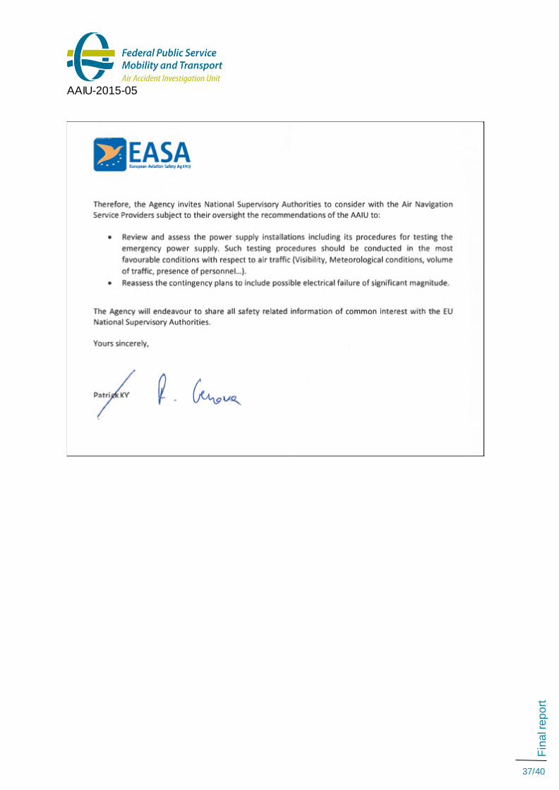
It is recommended that Belgocontrol review and assesses the power supply installations including its procedures for checking the emergency power supply. Such verification procedures should be conducted in the most favourable conditions with respect to air traffic, taking the following into account:
- Visibility - Meteorological conditions - Volume of traffic - Presence of personnel - Critical events (as an aircraft having declared an emergency).
AAIU-2015-05
Fin
al r
ep
ort
Ap
pe
nd
ice
s
32/40
4.3 Safety issue: Build Specifications
Recommendation: BE-2016-15: It is recommended that Belgocontrol would make sure that specific build specifications prepared for future installations and modification to installations involving a main power supply, include a specific requirement to ensure that the Earthing system be verified.
AAIU-2015-05
Fin
al r
ep
ort A
pp
en
dic
es
33/40
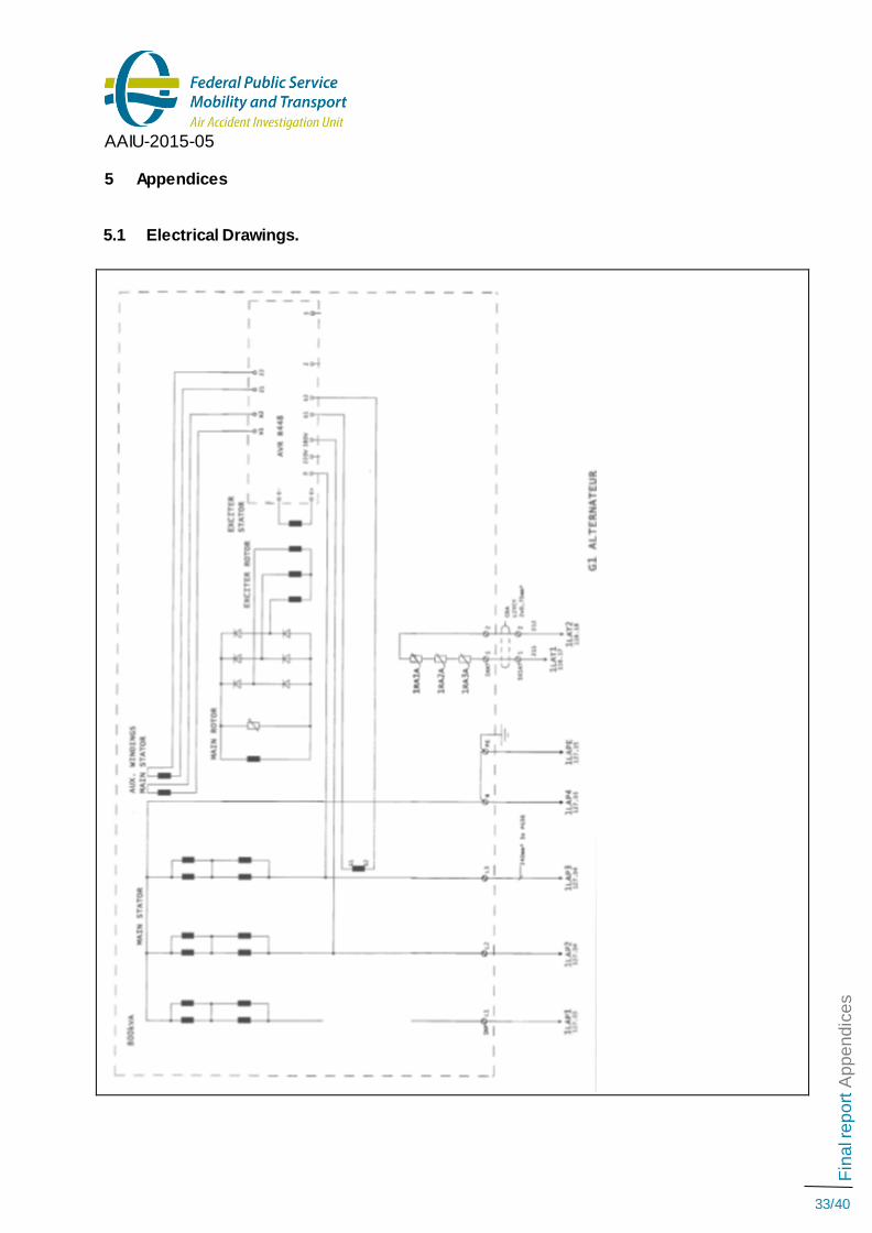
5 Appendices
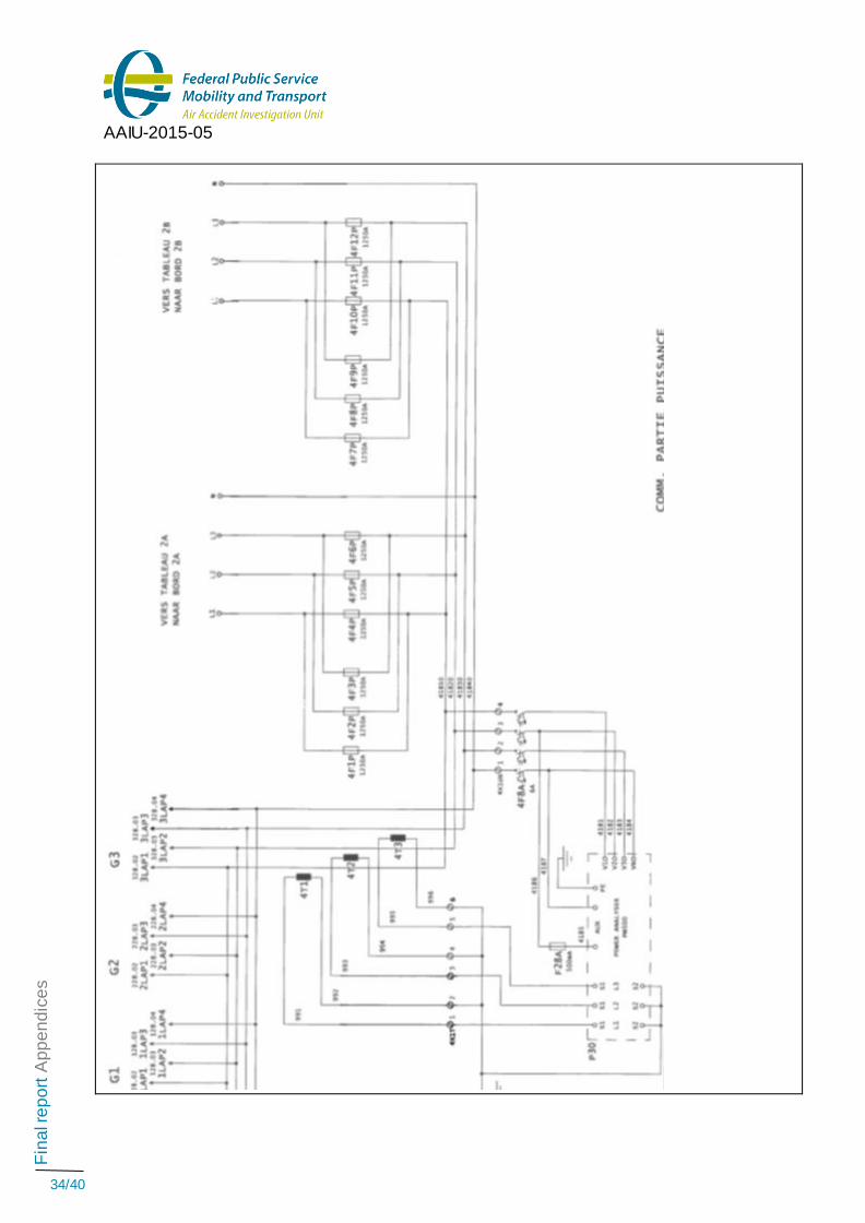
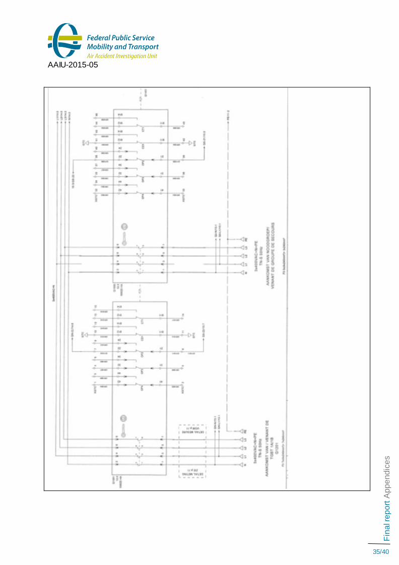
5.1 Electrical Drawings.
AAIU-2015-05
Fin
al r
ep
ort
Ap
pe
nd
ice
s
34/40
AAIU-2015-05
Fin
al r
ep
ort A
pp
en
dic
es
35/40
AAIU-2015-05
Fin
al r
ep
ort
Ap
pe
nd
ice
s
36/40
5.2 EASA letter to NSA
AAIU-2015-05
Fin
al r
ep
ort
37/40

AAIU-2015-05
Fin
al r
ep
ort
38/40
THIS PAGE IS INTENTIONALLY LEFT BLANK

AAIU-2015-05
Fin
al r
ep
ort
39/40
AAIU-2015-05
Fin
al r
ep
ort
40/40
Air Accident Investigation Unit - (Belgium)
City Atrium Rue du Progrès 56
1210 Brussels
Phone: +32 2 277 44 33
Fax: +32 2 277 42 60
www.mobilit.belgium.be