Embed Size (px)
Citation preview
1
Safety Integrity Level Compliant
Programmable System Design Presentation Embedded World 29 Feb 2012
Sebastian Stiemke, MissingLinkElectronics, Neu-Ulm
2 © Missing Link Electronics | Sebastian Stiemke
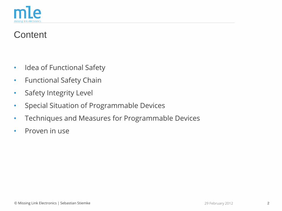
Content
• Idea of Functional Safety
• Functional Safety Chain
• Safety Integrity Level
• Special Situation of Programmable Devices
• Techniques and Measures for Programmable Devices
• Proven in use
29 February 2012

3
… yes – it is possible …

4 © Missing Link Electronics | Sebastian Stiemke
Idea of Functional Safety (acc. EN 61508)
Functional Safety is the ability of an electric/ electronic/programmable electronic system (E/E/PE) to stay in safe state or to initiate a coordinated safe state in case of an
• random and/ or systematic failures with dangerous impact to people, environment or serious machine damages
29 February 2012
© Rabbarien
5
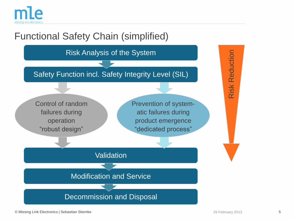
Decommission and Disposal
© Missing Link Electronics | Sebastian Stiemke 29 February 2012
Safety Function incl. Safety Integrity Level (SIL)
Modification and Service
Validation
Control of random
failures during
operation
“robust design”
Prevention of system-
atic failures during
product emergence
“dedicated process”
Functional Safety Chain (simplified)
Risk Analysis of the System
Ris
k R
eduction
6 © Missing Link Electronics | Sebastian Stiemke
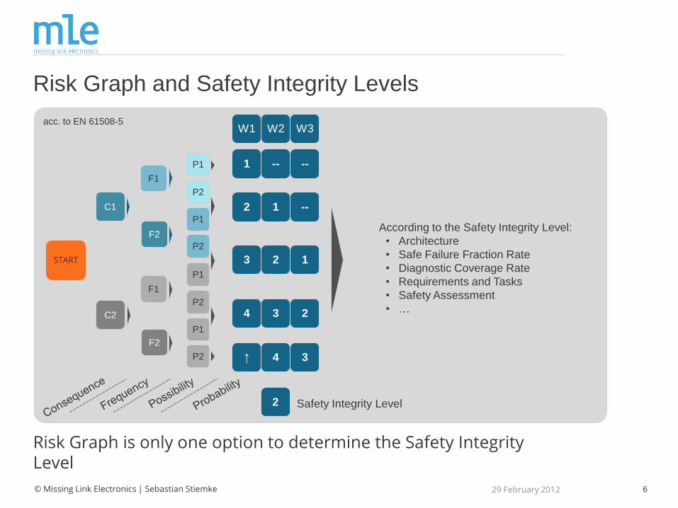
Risk Graph and Safety Integrity Levels
Risk Graph is only one option to determine the Safety Integrity Level
29 February 2012
1
2
3
4
↑
--
1
2
3
4
--
--
1
2
3
W1 W2 W3
2 Safety Integrity Level
acc. to EN 61508-5
C2
C1
F1
F2
F1
F2
P1
P1
P2
P2
P1
P1
P2
P2
START
According to the Safety Integrity Level:
• Architecture
• Safe Failure Fraction Rate
• Diagnostic Coverage Rate
• Requirements and Tasks
• Safety Assessment
• …
7 © Missing Link Electronics | Sebastian Stiemke
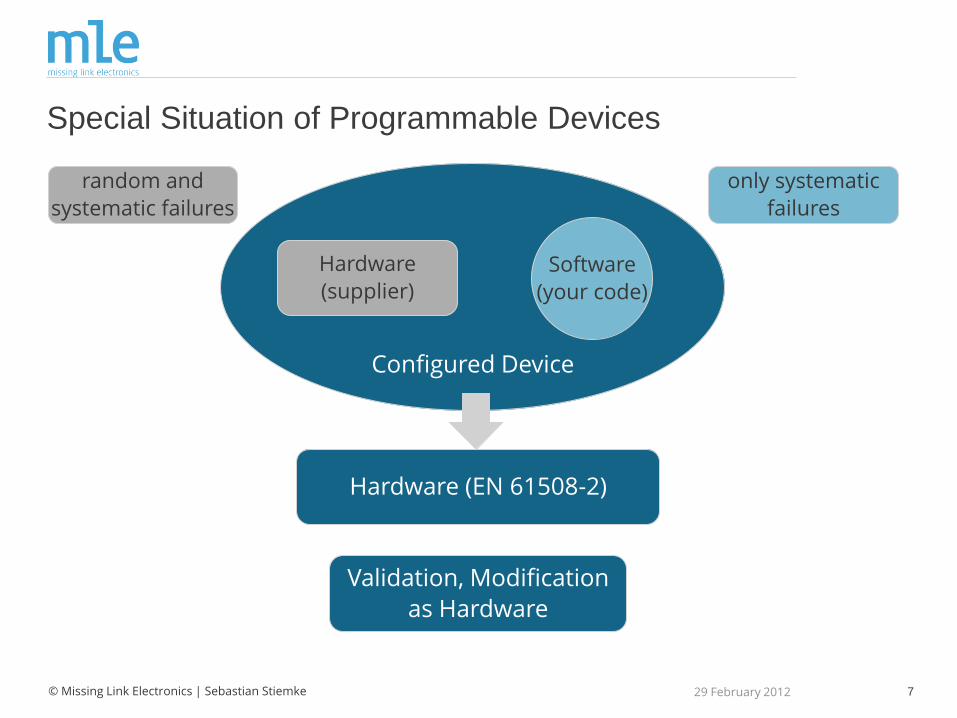
Special Situation of Programmable Devices
29 February 2012
Configured Device
Software
(your code)
random and
systematic failures
only systematic
failures
Hardware
(supplier)
Validation, Modification
as Hardware
Hardware (EN 61508-2)
8 © Missing Link Electronics | Sebastian Stiemke
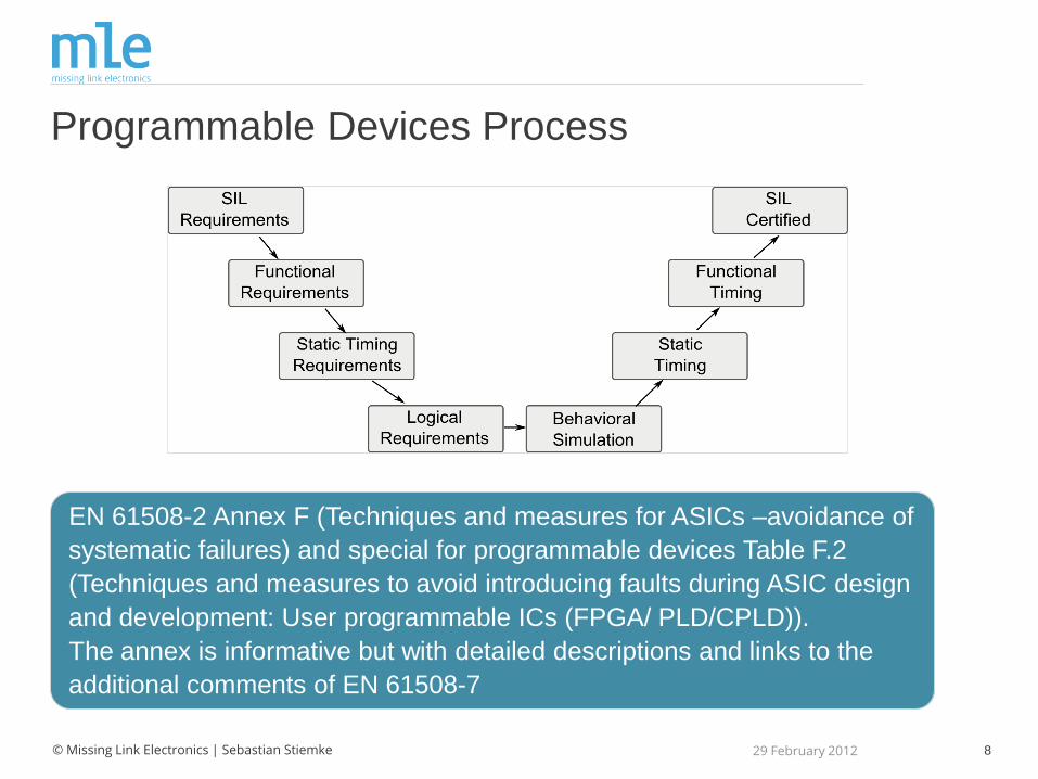
Programmable Devices Process
EN 61508-2 Annex F (Techniques and measures for ASICs –avoidance of
systematic failures) and special for programmable devices Table F.2
(Techniques and measures to avoid introducing faults during ASIC design
and development: User programmable ICs (FPGA/ PLD/CPLD)).
The annex is informative but with detailed descriptions and links to the
additional comments of EN 61508-7
29 February 2012

9 © Missing Link Electronics | Sebastian Stiemke
Technique and Measures (Annex F)
29 February 2012
Specification,
Reference Signals
VHDL/ RTL
Description Routing
Moduls,
Timing Simulation
TopLevelO1D
InternalResetGenerator ModulationClockGenerator PhaseMultiplexerInputSynchronization PMDResetGenerator OutAlignment
Synchronizer2FF ClockDivider2n ClockSelector RisingEdgeDetector PhaseShifter
TopLevelO1D
InternalResetGenerator ModulationClockGenerator PhaseMultiplexerInputSynchronization PMDResetGenerator OutAlignment
Synchronizer2FF ClockDivider2n ClockSelector RisingEdgeDetector PhaseShifter
Code inspection,
Funct. Simulation
HW Testing
Stat. Timing
Analysis
Configured Device
Synthesis
Manufacturing
10 © Missing Link Electronics | Sebastian Stiemke
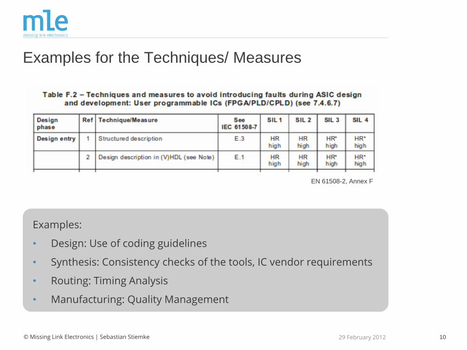
Examples for the Techniques/ Measures
Examples:
• Design: Use of coding guidelines
• Synthesis: Consistency checks of the tools, IC vendor requirements
• Routing: Timing Analysis
• Manufacturing: Quality Management
29 February 2012
EN 61508-2, Annex F
11 © Missing Link Electronics | Sebastian Stiemke
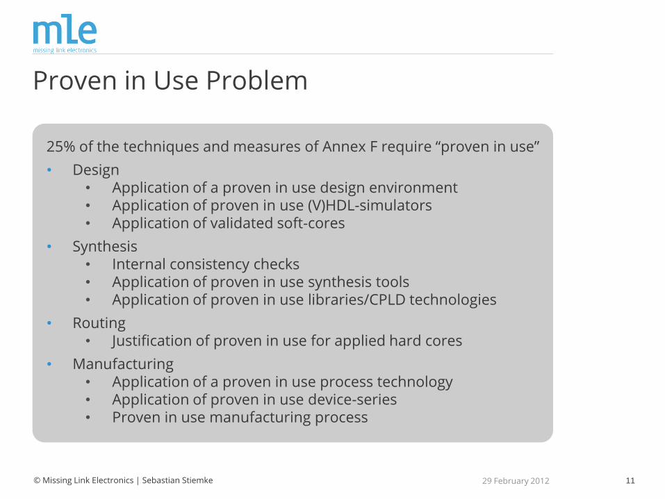
Proven in Use Problem
25% of the techniques and measures of Annex F require “proven in use”
• Design • Application of a proven in use design environment • Application of proven in use (V)HDL-simulators • Application of validated soft-cores
• Synthesis • Internal consistency checks • Application of proven in use synthesis tools • Application of proven in use libraries/CPLD technologies
• Routing • Justification of proven in use for applied hard cores
• Manufacturing • Application of a proven in use process technology • Application of proven in use device-series • Proven in use manufacturing process
29 February 2012
12
Block D
© Missing Link Electronics | Sebastian Stiemke
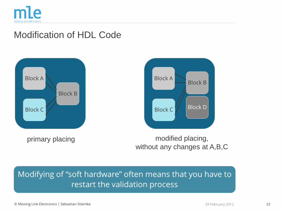
Modification of HDL Code
Modifying of “soft hardware” often means that you have to
restart the validation process
29 February 2012
Block A
Block C
Block B
Block A
Block C
Block B
primary placing modified placing,
without any changes at A,B,C

13 © Missing Link Electronics | Sebastian Stiemke
Solutions
Experience in programmable IC design is recommended for functional safety
• No asynchronous constructs (coding guideline)
• Modules with limited functions
• High level of automatic testing (test benches)
• Various responsibilities for design, testing and review, certification
• More detailed documentation not only results also reasons
29 February 2012
14 © Missing Link Electronics | Sebastian Stiemke
Conclusion
Functional Safety will become more important in the future for all industries. The probability that programmable devices will get safety function get higher as well
• It is possible
• “Proven in use” is the major item for hardware, tools and people
• Comprehensive testing, validation
• Detailed documentation with additional comments
• Reduced modifications
29 February 2012
15
Missing Link Electronics
Marlene-Dietrich-Straße 5
89231 Neu-Ulm
www.MLEcorp.com
Tel: +49 (731) 141-149-0