Embed Size (px)
Citation preview

Safety Instrumented Systemsand the AWAKE Plasma Cell Control as a Use Case
THCPA01, Functional safety and machine protection
Enrique Blanco (CERN)B. Fernandez, R. Speroni (CERN), Falk Braunmueller (MPI)
ICALEPCS'17 - Oct/17 E. Blanco - CERN 1

Outline
1. Goals2. AWAKE plasma cell3. Requirements4. Project lifecycle engineering: design5. Lessons learned and conclusions
ICALEPCS'17 - Oct/17 E. Blanco - CERN 2

GoalsOverview the LIFECYCLE of the safety instrumented system engineering
• Highlight the importance of the REQUIREMENTS: hazard identification and risk assessment
• Focus on the DESIGN phase using standards(1) Machine/installation/process was not designed with a safe mission (2) Use of not safety certified components
Functionality• Show the integration with a basic process control system (BPCS)
ICALEPCS'17 - Oct/17 E. Blanco - CERN 3

AWAKE• It is a proof-of-principle experiment
which explores the use of plasma to accelerate particles to high energies over short distances.
• Use SPS accelerator protons to create wakefields and then a second beam of electrons is accelerated to TeVenergies.
ICALEPCS'17 - Oct/17 E. Blanco - CERN 4
ILC Cavity: 35 MV/m Plasma cell: 35 GV/m 35 MV/mm !!No need of vacuum, no magnets nor RF
http://www.cern.ch/awake
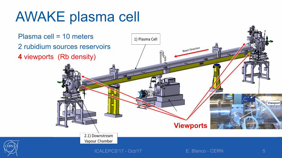
AWAKE plasma cellPlasma cell = 10 meters2 rubidium sources reservoirs 4 viewports (Rb density)
ICALEPCS'17 - Oct/17 E. Blanco - CERN 5
Viewports

Operational requirements1. Keeping the 10 meters plasma cell
isothermal (~220 oC) avoiding cold spots and possible intermediate rubidium condensation.
2. Avoiding temperature dispersion larger than 0.05 oC in some specific places
3. Providing a safe environment during operation with rubidium
ICALEPCS'17 - Oct/17 E. Blanco - CERN 6

Standards in Functional Safety Engineering IEC 61508: Functional Safety of Electrical/Electronic/Programmable Electronic Safety-Related Systems
IEC 61511: Functional safety for the Process Industry
ISA 84: Safety Instrumented Systems (SIS)
ICALEPCS'17 - Oct/17 E. Blanco - CERN 7
Functional safety standardsCopyright ©2017 TÜV Rheinland
ISA 84.01-1996 did not require a quantitative assessment of PFDavg. Instead, it stated that the user could rely on past performance of an existing SIS design as the basis for justification of its continued use.

Simplified lifecycle
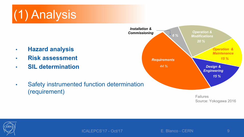
(1) Analysis• Hazard identification• Risk assessment• Safety functions
(2) Realization• Design• Installation• Commissioning
(3) Operation• Maintenance for SIL• Management of
change
ICALEPCS'17 - Oct/17 E. Blanco - CERN 8
Management of safety
(1) Analysis
• Hazard analysis• Risk assessment• SIL determination
• Safety instrumented function determination(requirement)
ICALEPCS'17 - Oct/17 E. Blanco - CERN 9
FailuresSource: Yokogawa 2016

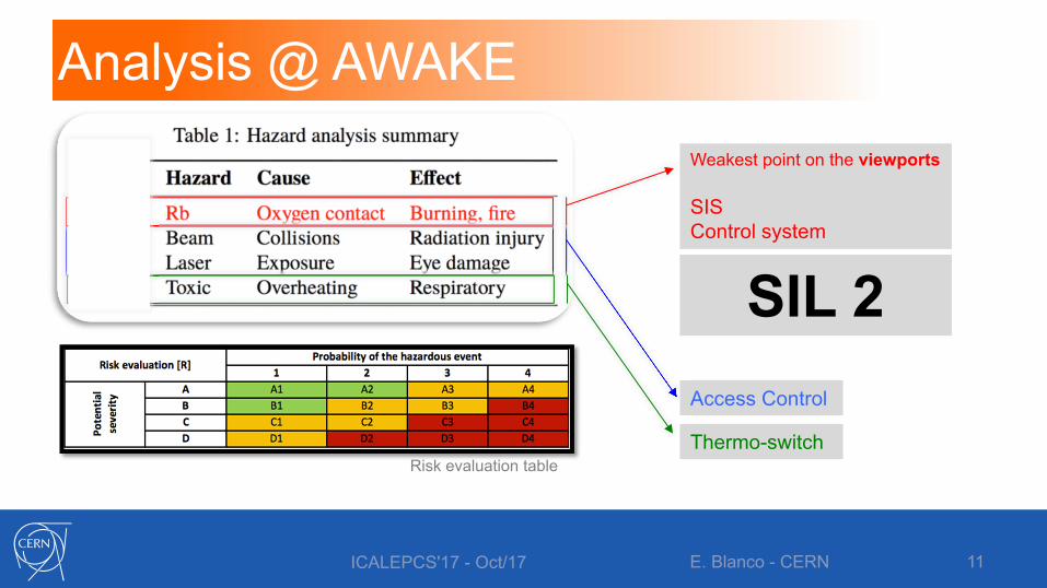
Analysis @ AWAKE• Safety file or the result of the hazard analysis and risk assessment• FMEA like document:
HazardsCausesHazardous eventsConsequencesRisk Actions
ICALEPCS'17 - Oct/17 E. Blanco - CERN 10
27 hazardous events analyzed
FMEA: Failure Modes and Effects Analysis
Analysis @ AWAKE
ICALEPCS'17 - Oct/17 E. Blanco - CERN 11
Access Control
Thermo-switchRisk evaluation table
Weakest point on the viewports
SIS Control system
SIL 2

Analysis @ AWAKESafety Instrumented Function (SIF): SIL 2Isolate the rubidium inside the plasma cell by closing the valves behind the viewports once a leak of the plasma cell is detected
ICALEPCS'17 - Oct/17 E. Blanco - CERN 12
Safety Instrumented Function LoopPlasma cell (viewports)

(2) Realization
ICALEPCS'17 - Oct/17 E. Blanco - CERN 13
Har
dwar
e Sa
fety
Inte
grity
• Quantify randomhardware failures
AND• Comply with requirements
for Architectural Constraints
Syst
emat
ic
Safe
ty In
tegr
ity
• Comply with requirements for systematic safety integrity
OR• Comply with requirements
for Proven in Use (PIU)
Procedure to achieve specified SIL IEC 61508

Hardware Safety IntegrityQuantify random hardware failures
ICALEPCS'17 - Oct/17 E. Blanco - CERN 14
IEC 61508 Low demand SIL determination
Safety Instrumented Function architecture Reliability Block Diagram
PFDTPG300
PFDTPG300
PFDPLC PFDET200 PFDvalv PFDvalv PFDvalv PFDvalv
2 31
CCFTPG300
PFD (Probability of failure under demand)
SIL PFDavg Risk Reduction4 10-5 ≤ PFD < 10-4 100,000 to 10,000
3 10-4 ≤ PFD < 10-3 10,000 to 1,000
2 10-3 ≤ PFD < 10-2 1,000 to 100
1 10-2 ≤ PFD < 10-1 100 to 10
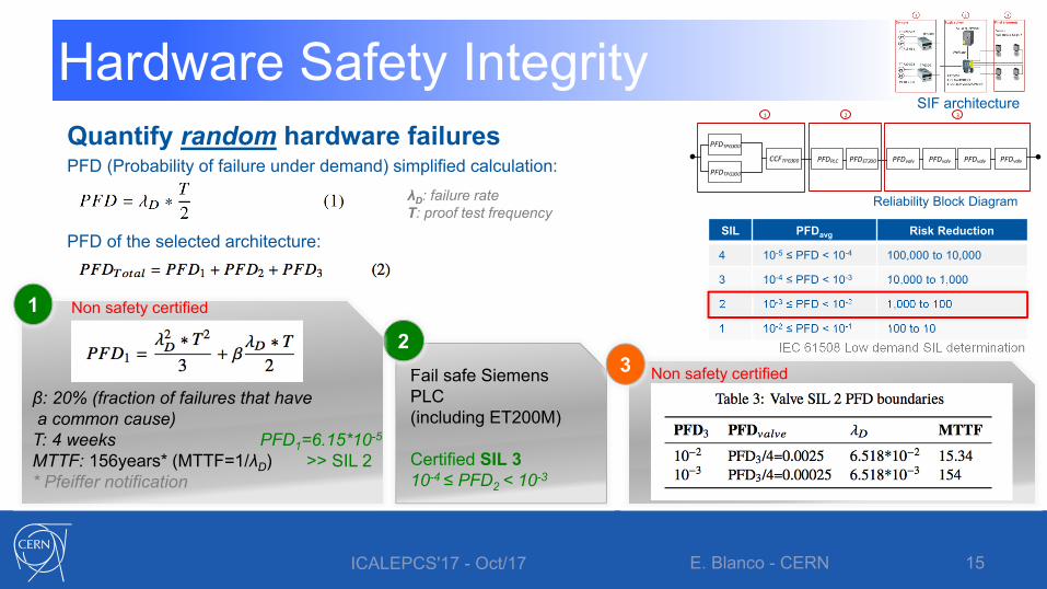
Quantify random hardware failuresPFD (Probability of failure under demand) simplified calculation:
PFD of the selected architecture:
Hardware Safety Integrity
ICALEPCS'17 - Oct/17 E. Blanco - CERN 15
IEC 61508 Low demand SIL determination
Reliability Block Diagram
SIF architecture
PFDTPG300
PFDTPG300
PFDPLC PFDET200 PFDvalv PFDvalv PFDvalv PFDvalv
2 31
CCFTPG300
λD: failure rate T: proof test frequency
Fail safe Siemens PLC(including ET200M)
Certified SIL 310-4 ≤ PFD2 < 10-3
2
SIL PFDavg Risk Reduction
4 10-5 ≤ PFD < 10-4 100,000 to 10,000
3 10-4 ≤ PFD < 10-3 10,000 to 1,000
2 10-3 ≤ PFD < 10-2 1,000 to 100
1 10-2 ≤ PFD < 10-1 100 to 10
β: 20% (fraction of failures that havea common cause)
T: 4 weeks PFD1=6.15*10-5
MTTF: 156years* (MTTF=1/λD) >> SIL 2 * Pfeiffer notification
1 Non safety certified
3 Non safety certified

Hardware Safety IntegrityArchitectural Constraints (IEC 61508 places an upper limit on the SIL that can be claimed for any SIF on the basis of the HFT of its subsystems)
ICALEPCS'17 - Oct/17 E. Blanco - CERN 16
Route 1H: based on:• HFT: Hardware failure tolerance• SFF: Safe Failure Fraction
Route 2H: gives more importance on components reliability given by users feedback.
SIF architecture
TPG300Type B: complexHFT=1Unknown SFF
Constraint:SFF > 60%
1 Solenoid valvesType A: simpleHFT=0Unknown SFF
SFF > 60%Otherwise need redundancy
3
Type: degree of confidence in the behavior under fault conditions
Type A Type B
HFTSFF
0 1 2 0 1 2
<60% SIL 1 SIL 2 SIL 3 N/A SIL 1 SIL 2
60% ≤ 90% SIL 2 SIL 3 SIL 4 SIL 1 SIL 2 SIL 3
90% ≤ 99% SIL 3 SIL 4 SIL 4 SIL 2 SIL 3 SIL 4
≥ 99% SIL 3 SIL 4 SIL 4 SIL 3 SIL 4 SIL 4
SFF= (Safe Failures + DD failures ) / ( All Failures )

Systematic safety integrity• Systematic capability (SC[1..4]). Measure of the confidence that the systematic
safety integrity meets the requirements of the specified SIL
ICALEPCS'17 - Oct/17 E. Blanco - CERN 17
Route 1sBased on techniques and measures for avoidance & control of systematic failure tables
TPG300SC1 compliantDesign (EMI, env. stress, online monitoring) Separated and redundant TPG300SC1 -> SC2
1 S7-315F (fail safe PLC)SIL 3 compliant for systematic fail.
(IEC 61511) Application software must be SIL2- Low variability Language (ladder)- Verification by formal methods*
2Solenoid valvesBasic information from supplier
The four valves must have an SC2 to claim the required SIL 2
3
* Formal verification: - PLCVerif: THPHA159- ITER use case: THPHA161
(1) Hardware & Software design(2) Environment(3) Operation

(3) OperationProof test
• Living system: Proof coverage is crucial for the SIL maintenance. • Proof coverage includes the full SIF and not only a particular element.
Operational procedures • Operators receive a full document on the safety functions• Alarms and events are included in the supervision HMIs (alarm systems)• Sometimes override of a SIF is possible, but this must be carefully monitored and detected
Management of change• Procedure ISA-84.00.01• All changes are traced and follow a strict procedure on validation before deployment. • Standard gives guidelines on what to test/verify again in case of a change.
ICALEPCS'17 - Oct/17 E. Blanco - CERN 18

BPCS: UNICOS-CPC framework
ICALEPCS'17 - Oct/17 E. Blanco - CERN 19
Simplified Main Finite State Machine
Integration & safety- BPCS: first layer of protection (no credit given)- Second layer of protection (important alarms)- Natural integration with the SIS- Monitoring of the SIS events & alarms (interface)
Control functionalities- PLC + SCADA based application - Based on the UNICOS-CPC framework (ISA-88)- 100 TT (PT100), 6 PT, 8 OnOff valves, 17 PWM - Get an isothermal behavior till ~ 220 OC

Lessons learned & conclusions✔ AWAKE plasma cell: equipment already designed without “safe” considerations:
• Meeting the specified SIL would need to replace the solenoid valves by other with safe characteristics, or proven reliability data, or a different architecture.
• Or the viewports could be reinforced, hence the SIL requirement lowered✔ Design engineering based on sector specific standards: IEC 61508 & IEC 61511 (ISA 84)
• SIL compliance: reliability of the hardware (random) and the architecture constraintsand systematic capabilities.
• Non safety classified equipment can be employed but requires additional information (maintenance database and user experience). But “Prior in use” or “Proven in use” claims require substantial evidence and cannot be easily be used
• Proof test frequency is a key factor• Allocate safety instrumented functions to the SIS and not to the BPCS.
✔ Formal verification of the solver logic becomes significant for the systematic capabilities
ICALEPCS'17 - Oct/17 E. Blanco - CERN 20

AcknowledgementsIndustrial Controls & Safety groupBeams DepartmentCERN, Geneva (Switzerland)
AWAKE team
MPI (Max Plank Institute, Germany)
Wright Design Limited (UK)
ICALEPCS'17 - Oct/17 E. Blanco - CERN 21
Falk Braunmueller
Patric Muggli
Erdem Öz
DanielEaston
RobertoSperoni
BorjaFernandez

Enrique Blanco ViñuelaAutomation engineer, PhD in systems and process engineering. Head of the Control Systems Engineering (AP) sectionIndustrial controls & safety group in the beams department at CERN