Embed Size (px)
Citation preview

2008 IWAKI CO., LTD.
IwakiElectromagnetic Metering PumpEWN-W (For water quality control)
Instruction manual Thank you for choosing our product.
Please read through this instruction manual before use.
This instruction manual describes important precautions and instructions for the product. Always keep it on hand for quick reference.
Safety instructionsO
utlineInstallation
Operation
Maintenance
SpecificationT696 '09/08
( )Country codes
IWAKI CO.,LTD. 6-6 Kanda-Sudacho 2-chome Chiyoda-ku Tokyo 101-8558 JapanTEL:(81)3 3254 2935 FAX:3 3252 8892(http://www.iwakipumps.jp)
Australia IWAKI Pumps Australia Pty. Ltd. TEL : (61)2 9899 2411 FAX : 2 9899 2421 Italy IWAKI Italia S.R.L. TEL : (39)02 990 3931 FAX : 02 990 42888Austria IWAKI (Austria) GmbH TEL : (43)2236 33469 FAX : 2236 33469 Korea IWAKI Korea Co.,Ltd. TEL : (82)2 2630 4800 FAX : 2 2630 4801Belgium IWAKI Belgium n.v. TEL : (32)1367 0200 FAX : 1367 2030 Malaysia IWAKIm Sdn. Bhd. TEL : (60)3 7803 8807 FAX : 3 7803 4800China IWAKI Pumps (Shanghai) Co., Ltd. TEL : (86)21 6272 7502 FAX : 21 6272 6929 Norway IWAKI Norge AS TEL : (47)66 81 16 60 FAX : 66 81 16 61China IWAKI Pumps (Guandong) Co., Ltd. TEL : (86)750 3866228 FAX : 750 3866278 Singapore IWAKI Singapore Pte. Ltd. TEL : (65)6316 2028 FAX : 6316 3221China GFTZ IWAKI Engineering & Trading (Guangzhou) TEL : (86)20 8435 0603 FAX : 20 8435 9181 Spain IWAKI Iberica Pumps, S.A. TEL : (34)943 630030 FAX : 943 628799China GFTZ IWAKI Engineering & Trading (Beijing) TEL : (86)10 6442 7713 FAX : 10 6442 7712 Sweden IWAKI Sverige AB TEL : (46)8 511 72900 FAX : 8 511 72922Denmark IWAKI Nordic A/S TEL : (45)48 24 2345 FAX : 48 24 2346 Switzerland IWAKI (Schweiz) AG TEL : (41)26 674 9300 FAX : 26 674 9302Finland IWAKI Suomi Oy TEL : (358)9 2745810 FAX : 9 2742715 Taiwan IWAKI Pumps Taiwan Co., Ltd. TEL : (886)2 8227 6900 FAX : 2 8227 6818France IWAKI France S.A. TEL : (33)1 69 63 33 70 FAX : 1 64 49 92 73 Taiwan IWAKI Pumps Taiwan (Hsin-chu) Co., Ltd. TEL : (886)3 573 5797 FAX : (886)3 573 5798Germany IWAKI EUROPE GmbH TEL : (49)2154 9254 0 FAX : 2154 9254 48 Thailand IWAKI (Thailand) Co.,Ltd. TEL : (66)2 322 2471 FAX : 2 322 2477Holland IWAKI Holland B.V. TEL : (31)297 241121 FAX : 297 273902 U.K. IWAKI PUMPS (UK) LTD. TEL : (44)1743 231363 FAX : 1743 366507Hong Kong IWAKI Pumps Co., Ltd. TEL : (852)2 607 1168 FAX : 2 607 1000 U.S.A. IWAKI America Incorporated TEL : (1)508 429 1440 FAX : 508 429 1386Indonesia IWAKI Singapore (Indonesia Branch) TEL : (62)21 690 6606 FAX : 21 690 6612 Vietnam IWAKI Pumps Vietnam Co.,Ltd. TEL : (84)613 933456 FAX : 613 933399

2 Order confirmation
Order confirmation
After unpacking, check the following points. Contact us or your nearest dealer if the delivery is imperfect.
a. Check if the delivery is as per order.Check the nameplate to see if the information such as model codes, discharge capacity and discharge pressure are as per order.
b. Check if the delivery is damaged or deformed.Check for transit damage and loose bolts.

3Contents
ContentsOrder confirmation ............................................................................................. 2
Safety instructions .......................................................................6
Warning ............................................................................................................. 7Caution .............................................................................................................. 8Precautions for use ........................................................................................10
Outline ......................................................................................... 12
Introduction .....................................................................................................12Pump structure & Operating principle .........................................................12Features .......................................................................................................13Operational function ....................................................................................13
Part names.......................................................................................................18Pump............................................................................................................18Operational panel ........................................................................................19
Basic displays & Pump states ............................................................... 20Identification codes ........................................................................................21
Pump/Drive units .........................................................................................21Sensors ........................................................................................................... 23
Conductivity sensor .................................................................................... 23
Installation ..................................................................................25
Pump mounting .............................................................................................. 25Pipework ......................................................................................................... 26
Tube connection ......................................................................................... 26Check valve mounting ................................................................................ 28
Sensor mounting ........................................................................................... 30Conductivity sensor .................................................................................... 30
Wiring ...............................................................................................................31Power supply/Earthing .................................................................................31End terminals .............................................................................................. 32Signal wire connection................................................................................ 34
STOP signal .......................................................................................... 35Input signal ............................................................................................ 36Output signal ......................................................................................... 36
Sensor cable connection .............................................................................37Terminal box .......................................................................................... 38

4 Contents
Multibox ...................................................................................................... 39Outline ................................................................................................... 39Installation ............................................................................................. 40Wiring .....................................................................................................41
Operation .....................................................................................43
Before operation ............................................................................................ 43Points to be checked .................................................................................. 43Retightening of pump head fixing bolts ...................................................... 43Degassing ................................................................................................... 44Before a long period of stoppage (One month or more) ..............................47
Operation programming ............................................................................... 48Programming flow ....................................................................................... 50Perform a calibration ...................................................................................51
Use of a conductivity sensor ..................................................................51Calibration for pH measurement ............................................................52AUTO calibration ................................................................................... 53MAN calibration ..................................................................................... 54Calibration for ORP measurement ........................................................ 56MAN calibration ..................................................................................... 57Conductivity calibration ......................................................................... 58
User mode .................................................................................................. 60User mode menu selection ................................................................... 60AUTO/MAN selection .............................................................................61Control parameter programming ........................................................... 62Measurement parameter programming ................................................. 64Function programming ...........................................................................67Display selection ....................................................................................73PIN number entry ...................................................................................74
AUTO operation ..............................................................................................75AUTO operation ...........................................................................................75MAN operation .............................................................................................76Priming function ...........................................................................................76Keypad lock ................................................................................................ 77
Keypad lock activation ........................................................................... 77Keypad lock release .............................................................................. 77Operation stop with a keypad lock state ................................................78

5Contents
Maintenance ................................................................................79
Troubleshooting ............................................................................................. 80Pump ..................................................................................................... 80Electrode/Sensor ....................................................................................81
Error codes ..................................................................................................... 83Error code information ........................................................................... 83Countermeasures .................................................................................. 84
Sensor maintenance ...................................................................................... 86Daily inspection .......................................................................................... 86
Precautions ........................................................................................... 86Inspection ....................................................................................................... 87
Daily inspection ...........................................................................................87Periodic inspection ......................................................................................87
Wear parts replacement ................................................................................ 88Wear parts list ............................................................................................. 88Before replacement .................................................................................... 89Valve set replacement ................................................................................ 89
Discharge valve set dismantlement/assembly ...................................... 89Suction valve set disentailment/assembly .............................................91
Diaphragm replacement ............................................................................. 92Exploded view ................................................................................................ 95
Pump head, Drive unit & Control unit ......................................................... 95Pump head ................................................................................................. 96
EWN- [VC•VH] ................................................................................... 96EWN-[B11•C16] [PC•PH]-H ...................................................................97
Specification/ Outer dimension ................................................................... 98Specification ............................................................................................... 98
Pump unit .............................................................................................. 98Control unit .......................................................................................... 100Power cable ..........................................................................................101Pump colour .........................................................................................101
Outer dimensions.......................................................................................102EWN- [B09•11•16•21C16•21][VC•VH](-C) ............................................102EWN-[B31•C31] [VC•VH] .....................................................................102EWN- C36 [VC•VH] ..............................................................................103EWN-[B11•C16] [PC•PH]-H .................................................................103

6
Read through this section before use. This section describes important information for you to prevent personal injury or property damage.
■ Pictorial indicationIn this instruction manual, the estimated risk of degree caused by incorrect use is ranked with the following pictorial indications. First, fully understand informa-tion on the pictorial indications.
Indicates mishandling could lead to a fatal or seri-ous injury accident.WARNING
Pictorial indication accompanies each precaution, suggesting "Caution", "Prohi-bition" and "Requirement".
Indicates mishandling could lead to personal or property damage.CAUTION
Caution marks Prohibition mark Requirement mark
Safety instructions
Safety instructions
ProhibitionElectricalshock
Caution Do not remodel Requirement Wearprotectors
Earthing
For exportationTechnology related to the use of goods in this instruction manual falls in the category of technology contained in the Foreign Exchange Order Attachment, which includes complementary export control of technology. Please be remind-ed that export license, which is issued by the Ministry of Economy, Trade, and Industry could be required, when this is exported or provided to someone even in Japan.
7
Safety instructions
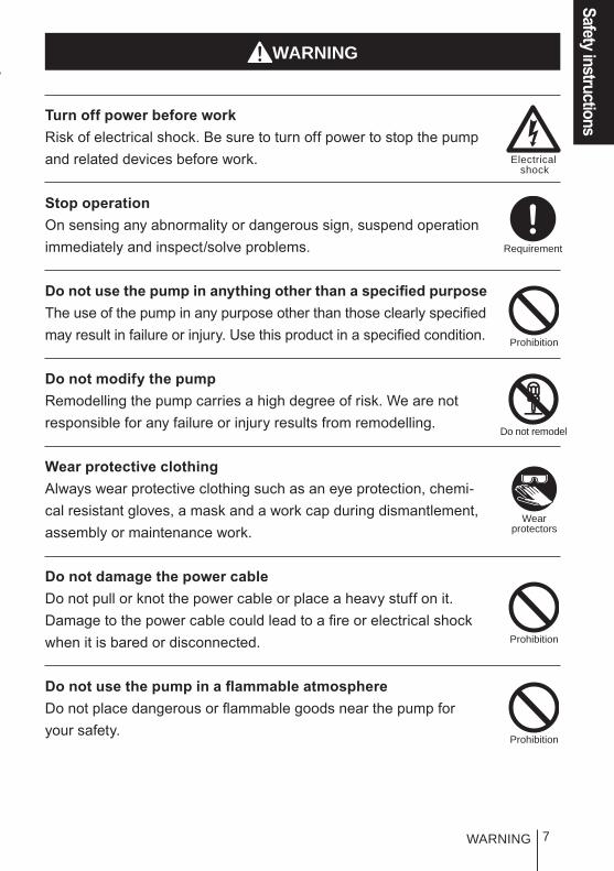
WARNING
Turn off power before workRisk of electrical shock. Be sure to turn off power to stop the pump and related devices before work.
Stop operationOn sensing any abnormality or dangerous sign, suspend operation immediately and inspect/solve problems.
Do not use the pump in anything other than a specified purposeThe use of the pump in any purpose other than those clearly specified may result in failure or injury. Use this product in a specified condition.
Do not modify the pumpRemodelling the pump carries a high degree of risk. We are not responsible for any failure or injury results from remodelling.
Wear protective clothingAlways wear protective clothing such as an eye protection, chemi-cal resistant gloves, a mask and a work cap during dismantlement, assembly or maintenance work.
Do not damage the power cableDo not pull or knot the power cable or place a heavy stuff on it. Damage to the power cable could lead to a fire or electrical shock when it is bared or disconnected.
Do not use the pump in a flammable atmosphereDo not place dangerous or flammable goods near the pump for your safety.
WARNING
Prohibition
Requirement
Do not remodel
Wearprotectors
Electricalshock
Prohibition
Prohibition
8 CAUTION
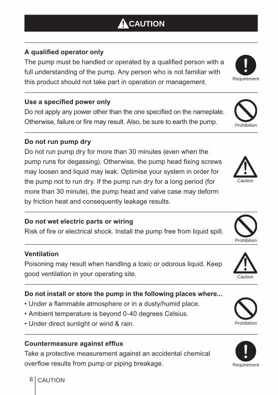
A qualified operator onlyThe pump must be handled or operated by a qualified person with a full understanding of the pump. Any person who is not familiar with this product should not take part in operation or management.
Use a specified power onlyDo not apply any power other than the one specified on the nameplate. Otherwise, failure or fire may result. Also, be sure to earth the pump.
Do not run pump dryDo not run pump dry for more than 30 minutes (even when the pump runs for degassing). Otherwise, the pump head fixing screws may loosen and liquid may leak. Optimise your system in order for the pump not to run dry. If the pump run dry for a long period (for more than 30 minute), the pump head and valve case may deform by friction heat and consequently leakage results.
Do not wet electric parts or wiringRisk of fire or electrical shock. Install the pump free from liquid spill.
VentilationPoisoning may result when handling a toxic or odorous liquid. Keep good ventilation in your operating site.
Do not install or store the pump in the following places where...• Under a flammable atmosphere or in a dusty/humid place.• Ambient temperature is beyond 0-40 degrees Celsius.• Under direct sunlight or wind & rain.
Countermeasure against effluxTake a protective measurement against an accidental chemical overflow results from pump or piping breakage.
CAUTION
Prohibition
Requirement
Prohibition
Prohibition
Caution
Caution
Requirement

9
Safety instructions
CAUTION
Do not use the pump in a water placeThe pump is not totally waterproof. The use of the pump in water or high humidity could lead to electrical shock or short circuit.
EarthingRisk of electrical shock. Always earth the pump.
Install an earth leakage breakerAn electrical failure of the pump may adversely affect related de-vices. Purchase and install an earth leakage breaker separately.
Wear part replacementFollow instructions in this manual for wear part replacement. Do not dismantle the pump beyond the extent of the instructions.
Do no use a damaged pumpUsing a damaged controller could lead to an electric leak or shock.
Disposal of the used pumpDispose of any used or damaged pump in accordance with relevant regulations. Consult a licensed industrial waste products disposing company.
Tighten the pump headLiquid may leak if four pump head fixing bolts are loose. Tighten the bolts diagonally and evenly before an initial operation. Also, periodi-cally tighten the bolts for the prevention of leakage.
Tightening torqueEWN-B09•11•16•21, C16•21 : 2.16 N•m
EWN-B31, C31•36 : 2.55 N•m
Install a relief valveInstall a relief valve on the discharge line near the pump and re-lease the discharge pressure when it exceeds the maximum level.
Earthing
Prohibition
Requirement
Requirement
Caution
Prohibition
Requirement
Electricalshock

10 Precautions for use
• Electrical work should be performed by a qualified opera-tor. Otherwise, personal injury or property damage accident may result.
• Do not install the pump in the following places where...–Under a flammable atmosphere or in a dusty/humid place.–Under direct sunlight or wind & rain.– Ambient temperature is beyond 0-40 degrees Celsius. Protect the pump with a cover when installing it out of doors.
• Select a level location where is free from vibration and liquid can't stay. Fix the pump with M5 bolts so as not to vibrate. If the pump is installed at a tilt, the flow may reduce.
• When two or more pumps are installed, the pump opera-tion interacts each other and vibration becomes significant, resulting in poor performance or failure of internal electri-cal devices. Select an installation location where tolerates vibration to enough degree.
• Keep a wide maintenance space around the pump.
• Install the pump as close to a supply tank.
• Install the pump in a cool and dark place when handling liquids that readily generate gas bubbles such as sodium hypochlorite or hydrazine solution. Flooded suction applica-tion is strongly recommended when using the pump with a supply tank.
Precautions for use
Caution
Caution
Caution
Caution
Caution

11
Safety instructions• Be careful not to drop the pump onto the floor. A strong
impact may reduce pump performance. Do not use a pump which has once damaged. Otherwise an electrical leak or shock may result.
• The pump is a light water-/dust-proof structure of IP65, but is not totally waterproof. Do not have the pump wet with the liquid handled or rainwater.
• Never wet the pump head, control unit and drive unit. Oth-erwise, Failure or an accident may result. Immediately wipe off liquid if the pump has got wet.
• Do not close the discharge line during operation. Other-wise, liquid may leak or tubing may break. Install a relief valve to be sure to prevent a leak or a tubing break
• Do not remove the control unit. Note that an applicable con-trol unit differs with each drive unit. Do not attach a control unit to a different drive unit. Otherwise, an electrical circuit or the drive unit may fail.
• Release the pressure from the discharge line before dis-mantling the pump or removing tubing. Otherwise, chemical liquid gushes out.
• Be careful not to come in contact with residual liquid.
• Do not clean the pump or nameplate with a solvent such as benzene and thinner. This may discolour the pump or erase printing. Use a dry cloth or a wet cloth with water or neutral detergent.
Precautions for use
Caution
Caution
Caution
Caution
Caution
Requirement
Benzine
Thinner

12
Outline
Introduction
The information such as characteristics, features and part names are described in this section.
Introduction
Pump structure & Operating principleThe EWN-W is a diaphragm type electromagnetic metering pump which automatically monitors and controls water quality by means of electrodes and sensors.
Principle of operationThe pulse signal controls the electromagnetic force and spring force in order to make reciprocating motion. The reciprocating motion is transferred to a diaphragm through a plunger and then volumetric change occurs in the pump head. This action transfers liquid along with pump head valve action.
Control unit Pump headDrive unit
OUT
IN
SpringPump head valve(Discharge side)
Pump head valve(Suction side)
Plunger
Diaphragm

13
Outline
Introduction
Features● Automatic control
The EWN-W automatically monitors and controls water quality by means of electrodes and sensors.
WPO type: Controls a flow rate in proportion to the pH or ORP value measured by electrodes.
WEC type: Controls a flow rate in proportion to the conductivity measured by sensors.
WCT type: Controls a blowdown valve along with the conductivity meas-ured by sensors.
● Multi voltageThe EWN-W is multivoltage type (100-240VAC) and can be selected without concern for local power voltage.
● Waterproof and dustproof structure (IP65)This pump is hermetically sealed at the drive unit, control unit and the pump head separately in order to ensure a certain level of water-/dust-proof that is equal to IP65.* This pump is not completely water resistant. Protect the pump with a cover when
installing it out of doors.
Operational function● AUTO operation (see page 75)
The external sensor signal (pH/ORP or conductivity) controls the pump operation. The AUTO operation acts as the proportional control, PID control and blowdown control.
Proportional control (WPO/WEC)In this mode the pump controls stroke rate in proportion to the measured pH/ORP value or conductivity. Program stroke rates at two different points before operation.
<Example of program parameters>SP.1 pH: 7.00
spm: 0SP.2 pH: 10.00
spm: 360
spm
pH20
90
180
270
360
4 6 87
10 12 14
SP.1
SP.2

14 Introduction
PID control (WPO/WEC)Programming integral and derivative values compensates deviation in the propor-tional control. See the following formula.
spm=Kp×Deviation + Ki×Accumulated deviation + Kd (Previous deviation- deviation)
Kp: Proportional gain (calculated by SP.1 and SP.2)Ki: Integral gain (Kp/Ti Ti=Integral term)Kd: Derivative gain (Kp×Td Td=Derivative term)Deviation: Process value (PV) - Setpoint (SP)Accumulated deviation: Summed instantaneous deviation
Blowdown control (WCT)The pump controls a blowdown valve along with the measured conductivity.In this control there are two operation.* The multibox (relay type) is required to supply power in this control.
• Interval operationThe pump runs separately from the blowdown operation.
ONOFF
ONOFF
0:40 0:20
Starting point
Stop point
Conductivity
Blowdown
Pump operation
Operating time Down time

15
Outline
• Synchronized blowdown operationThe pump runs in sync with the blowdown operation. Lockout and a time limit can also be programmed.
● Manual operation (see page 76)The start/stop of the pump by key operation
*Operation can be stopped or resumed by plugging in or off.
Introduction
ONOFF
ONOFF
ON
ON
OFF
OFF
Starting point
Stop point
Conductivity
Blowdown
Pump operation
Pump operationlockout
Pump operationlockout+TIme limit
Key operation(Push key)
Pump operation
Run
Stop
Run
Stop

16 Introduction
● AUX functionThe pump runs at the maximum stroke rate while receiving the external sig-nal via the AUX terminal. Use this function for degassing.
● Priming function (See page 76)The pump runs at the maximum stroke rate while both the UP and DOWN keys are pressed. Use this function for degassing.
● OUTPUT function (See page 69)Signals can be sent via the output terminal in sync with programming.
OUT1 (Mechanical relay)The upper alarm and lower alarm function via OUT1.<Example>
Interlock, STOP, Pre-STOP, AUX and Sensor failure alarms can be programmed to the OUT1.
AUX signal input
Pump operation
Run
Stop
Run
Stop
+
Pump operation
Run
Stop
Run
Stop
Press Press
Alarm output
pHOFF
ON
11 12 13pHOFF
ON
1 2 3
Upper alarm setpoint 12pH
Hysteresis is 2pH.
Lower alarm setpoint 2pH
Hysteresis is 2pH.

17
Outline
Introduction
OUT2 (PhotoMOS relay)The synchronization signal in sync with stroke rates can be outputted as well as the above alarms.
● STOP function (See page 68)The start/stop of the pump can be controlled by the external signal from a level sensor or other devices.
When "NOR. OP" is selected...The pump stops while receiving the external signal via the STOP terminal (closed contact).
*The pump resumes operation when the STOP signal is released.
When "NOR. CL" is selected...The pump runs while receiving the external signal via the STOP terminal (closed contact).
*The pump stops operation when the stop signal is released.
● Pre-STOP function
When "NOR. OP" is selected...The STOP LED lights orange while the pump receiving the external signal via the Pre-STOP terminal (closed contact).
When "NOR. CL" is selected...The STOP LED stops lightening while the pump receiving the external signal via the Pre-STOP terminal (closed contact).
The pump stops running while the STOP signal is inputted.
STOP signal input
Pump operation
Run Run
Stop
Run
StopStop
STOP signal input
Pump operation

18
Part names
Pump
Part names
Control unitUsed for the start/stop of the pump and stroke rate adjust-ment/programming. See next page for detail.Air vent port
Always connect a tube. Be sure to return the tube end to the supply tank or another container.The air vent port can rotate 90 degrees.
Adjusting screwUsed for opening the air vent port.
NameplateDescribes the pump specification.
BaseAlways fix with bolts.
Pump head
Inlet
Outlet
Air vent body

19
Outline
Operational panel
Part names
DOWN keyUsed for decreasing numeric values or selecting a programming mode.
CAL keyUsed for moving to the calibration mode.
UP keyUsed for increasing numeric values or selecting a programming mode.
DisplayAn operational status, current mode and programmed value are shown here.
Start/stop keyUsed for starting/stopping the pump operation or moving between modes.
ON LEDLights orange as turning on power.The LED lights greenly and flashes at each stroke.
ESC keyUsed for cancelling current programming and moving back to a previous menu.
OUT LEDLights redly as the pump output the signal.
STOP LEDLights redly as the pump stops run-ning by the STOP signal Lights orange as the pump keeps run-ning while receiving the Pre-STOP signal.
SET keyUsed for entering current programming. Pressing this key for one second, the pump enters the user mode.

20
■ Basic displays & Pump statesSTOP LED lights redly
ON LED lights orange
ON LED blinks greenly
OUT LED lights redly
―Manual wait state. Display shows pH value.
―OUT1 & 2 function as programmed.
― ―
Operation in manual mode. Display shows pH and stroke rate in %. 360spm is at 100%.
OUT1 & 2 function as programmed.
―
Wait state in Auto mode. Display shows pH value and temperature.
Operation in Auto mode. Display shows pH value and temperature.
OUT1 & 2 function as programmed.
Operation stop by the STOP signal
― ― ―
―Programming in the User mode ― ―
―Programming at SP.1 ― ―
Programming in the calibra-tion mode
― ― ―
―Auto calibration is in process ― ―
Error oc-curred. ― ― ―
― ―
PRIME mode. Operation at the maximum stroke rate
―
― ―
AUX mode. Operation at the maximum stroke rate
―
Part names

21
Outline
Identification codes
The model codes of the pump/drive units and the control unit represent the fol-lowing information.
Pump/Drive units
EWN - B 11 VC J WPO - a b c d e f g h i
a. Series nameEWN: Multivoltage electromagnetic metering pump
b. Drive unit code (Average power consumption)B: 20WC: 24W
c. Diaphragm effective diameter09: 8mm 11: 10mm 16: 15mm21: 20mm 31: 30mm 36: 35mm
d. Wet end materialsCode Pump head Valve O ring Valve seat Gasket Diaphragm
VCPVC
Alumina ceramic FKM FKM
PTFE PTFE+ EPDM
VH HC276 EPDM EPDM
PCGFRPP
Alumina ceramic FKM FKM
PH HC276 EPDM EPDM
Material codePVC : Transparent polyvinyl chlorideGFRPP : Glassfiber-reinforced polypropyleneEPDM : Ethylene-propylene rubberFKM : Fluorine-contained rubberPTFE : PolytetrafluoroethyleneHC276 : HASTELLOY C276
Identification codes

22
e. Tube connection bore codeNo. Hose size (ID×OD) Wet end materials Pump model
No code*
ø4×ø6 VC/VH/VC-C/VH-C EWN-09/-11/-16 & -21ø9×ø12 VC/VH EWN-31 & -36ø6×ø12 VC-C/VH-C EWN-09/-11/-16 & -21
IN/AIR: ø4×ø6 OUT: Rc 1/4 PC/PH-H EWN-11 & -16
1 ø4×ø9 VC/VH/VC-C/VH-C EWN-09/-11/-16 & -213 ø6×ø8 VC/VH/VC-C/VH-C EWN-09/-11/-16 & -214 ø8×ø13 VC/VH EWN-31 & -366 ø10×ø12 VC/VH EWN-31 & -367 ø1/4"×ø3/8" VC/VH/VC-C/VH-C EWN-09/-11/-16 & -218 ø3/8"×ø1/2" VC/VH EWN-31 & -36
23 ø6×ø12 VC EWN-11/-16/-21/-31 & -36
24 ø5×ø8 VC/VC-C EWN-09/-11/-16 & -21
* No code. ø4×ø6 and ø6×ø12 are equipped to the EWN-09, -11, -16 & -21 (the VC or
VH-C types).
f. Power codeE: European cord
g. Control unit function codeWPO: pH/ORPWEC: ConductivityWCT: Cooling tower
h. Special version codeC: High compression typeH: High pressure type
i. Special configuration code
Identification codes

23
Outline
Sensors
Sensors
The EWN-W always needs sensors during operation.
Observe the following points for sensor.
• Do not cause mechanical damage to the pump. The sensor may fail.• Do not touch a glass membrane with bare hands. Sensitivity may reduce
when the membrane is contaminated by sebum.• The sensor is a ware part. Replace it with new one periodically.
● Conductivity sensorUse the designated conductivity sensor.
Immersion mounted sensor: ESC-150P1-06YVThis type of sensor is placed in a tank. There are two vertical probes at the sensor end.
S T T E2
E1

24
InLine mounted sensor: CS150TC-YThis type of sensor is placed in a pipeline through a flow cell. There are two probes in a slot at the sensor end.
S T T E2
E1
Sensors

25
Installation
This section describes the installation of the pump, tubing and wiring. Read through this section before work.
Observe the following points when installing the pump.
• Be sure to turn off power to stop the pump and related devices before work.• Upon sensing abnormal condition or a dangerous sign, stop the work im-
mediately. Remove problems before resuming work.• Do not place dangerous or flammable goods near the pump for your safety.• Risk of an electrical leak or shock. Do not use a damaged pump.
Pump mounting
Select an installation location and mount the pump.
Necessary tools• Four M5 bolts (pump mounting)• Adjustable wrench or spanner
Select a suitable place.Always fix the pump on a flat floor free of vibration. See page 10 for detail.Flooded suction application is recommended when handling a gaseous liquid such as sodium hypochlorite.
Fix the pump by the M5 bolts.Be sure to fix the pump at four points.
NOTEInstall the pump horizontally. If the pump is installed at a
tilt, the flow may reduces.
1
2
Installation
Pump mounting
26
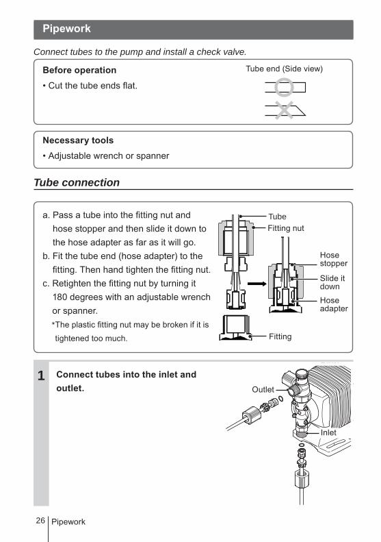
Pipework
Connect tubes to the pump and install a check valve.
Before operation• Cut the tube ends flat.
Necessary tools• Adjustable wrench or spanner
Tube connection
a. Pass a tube into the fitting nut and hose stopper and then slide it down to the hose adapter as far as it will go.
b. Fit the tube end (hose adapter) to the fitting. Then hand tighten the fitting nut.
c. Retighten the fitting nut by turning it 180 degrees with an adjustable wrench or spanner.* The plastic fitting nut may be broken if it is
tightened too much.
Connect tubes into the inlet and outlet.
Tube end (Side view)
1
TubeFitting nut
Fitting
Slide itdown
Hosestopper
Hoseadapter
Pipework
Outlet
Inlet

27
InstallationConnect an air bleed tube into the air vent port.Place the tube end in the supply tank or another container.
Direction of the air vent port.The air vent port can rotate 90 de-grees.
a. Turn the lock nut anticlockwise.
b. Adjust the direction of the air vent port.
c. Turn the lock nut clockwise and fix it, holding the air vent body A.
d. Further tighten the lock nut by turn-ing it 90 degrees with an adjustable wrench or spanner.
2
3
Air vent port
Lock nutAir vent body A
Pipework

28
Check valve mountingInstall an optional check valve to the EWN for the prevention of a back flow, siphon and overfeeding.In the following cases be sure to install the check valve.
• The suction side liquid level is higher than the discharge side (See the diagram below). Or an injection point is below the suction side liquid level at atmospher-ic pressure.
• The elevation difference between two liquid levels is five meters or below, even if the discharge side liquid level is higher than the suction side.
• Suction side pressure is higher than the discharge side pressure.
• Discharge pressure (including pipe resistance and discharge head) is below 0.13MPa. (0.049MPa for B31 and C36).
Suction side
Discharge side
Suction side
Discharge side5m or below
Pipework

29
InstallationMount the check valve at the discharge tube end.* The CAN check valve has R1/2 and R3/8 thread connections as well as tube connection. Cut off and adjust the connection length to fit the check valve into tubing.
CAN check valve
* The CBN check valve of which the both ends are tube connection is also avail-able. Contact us or your nearest dealer.
CBN check valve
NOTEPeriodically clean or replace the check valve with new one because it may be clogged by crystal. Tubing layout Flooded suction application Suction lift application
* Flooded suction application is recommended when handling a gaseous liquid such as sodium hypochlorite.
NOTEInstall a relief valve if the discharge line may clog.
Outer dia Ф9R1/2
R3/8
1
Pipework
Check valve
Accumulator/ChamberAccumulator/Chamber
Check valve
Pump
Pump
Air vent line
Air vent line
Relief valveRelief valve

30
Sensor mounting
pH/ORP electrodeObserve the instruction manual of the pH/ORP electrode. Always select "MTC" in AUTO/MAN TC selection. See page 66 for detail.
Conductivity sensor
● Immersion mounted sensorPlace the sensor into a tank. Insure that the sensor is surrounded by at least 30mm of liquid on all sides, including top and bottom. Otherwise, an accu-rate measurement can not be obtained.
Min. liquid level
30mm or more
30mm or more
150mm or more
Max. liquid level
Allowable range
Sensor mounting

31
Installation
Wiring
Wiring
Wiring for the power source and external signal.
Observe the following points during wiring work.
• Electrical work should be performed by a qualified operator. Always ob-serve applicable codes or regulations.
• Observe the rated voltage range. Otherwise the electrical circuit on the control unit may break.
• Do not perform wiring work while the power is on. Otherwise, an electri-cal shock and short circuit may result, and consequently the pump may fail. Be sure to turn off power before wiring work.
• Be careful for the power not to be turned on during work.• Replacement of a power cable should be conducted by a manufacturer,
his agency or a skilled person. Otherwise, an accident may result.
Necessary tools• Adjustable wrench or spanner • Phillips screw driver
• Precision screw driver
Power supply/Earthing
Check that the main power is turned off.
For the WPO and WEC types, in-sert the plug all the way seated in a socket.For the WCT, connect power wires and earth wire to correct terminals.This product has two power wires and one earth wire, and is classified as class Ι.* Make sure the earth plug is connected as well.
1

32
End terminalsSee the following diagram for detail.
Input terminal
STOP terminal
Output terminal
Sensor signal
<WCT>Power wires (1950mm)
<WPO/WEC>Power cable (1950mm)
Wiring

33
InstallationNOTE• Do not share a power source with a high power equipment which may generate surge
voltage. Otherwise electronic circuit may fail. The noise caused by the inverter also
affects the electronic circuit.
• Power voltage should be charged at a sitting via a switch or a relay. Otherwise CPU
may malfunction. See page 34 for the precautions for ON-OFF control by the relay.
Apply the power at a sitting Do not apply gradually
Surge voltageThe electronic circuit in the control unit may fail due to surge voltage. Do not place the pump close to the high power equipment of 200V or more which may generate large surge voltage.If the use near the high power equipment is inevitable, take any of the fol-lowing measures.
• Install a surge absorption element (ex. a varister with capacity of 2000A or more) via power cable.
Recommended varistersPanasonic ERZV14D431KOA NVD14UCD430See manufacturer's catalogues for detail.
• Install a noise cut transformer via power cable.
POWERON
OFF TIMEPOWER
ON
OFF TIME
Surge absorption element
Noise cut transformer
Wiring
34
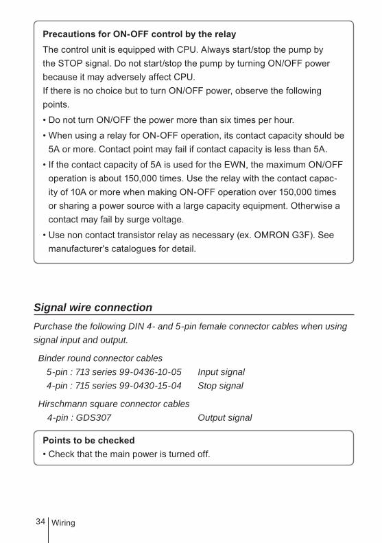
Precautions for ON-OFF control by the relayThe control unit is equipped with CPU. Always start/stop the pump by the STOP signal. Do not start/stop the pump by turning ON/OFF power because it may adversely affect CPU.If there is no choice but to turn ON/OFF power, observe the following points.
• Do not turn ON/OFF the power more than six times per hour.
• When using a relay for ON-OFF operation, its contact capacity should be 5A or more. Contact point may fail if contact capacity is less than 5A.
• If the contact capacity of 5A is used for the EWN, the maximum ON/OFF operation is about 150,000 times. Use the relay with the contact capac-ity of 10A or more when making ON-OFF operation over 150,000 times or sharing a power source with a large capacity equipment. Otherwise a contact may fail by surge voltage.
• Use non contact transistor relay as necessary (ex. OMRON G3F). See manufacturer's catalogues for detail.
Signal wire connection Purchase the following DIN 4- and 5-pin female connector cables when using signal input and output.
Binder round connector cables 5-pin : 713 series 99-0436-10-05 Input signal 4-pin : 715 series 99-0430-15-04 Stop signal
Hirschmann square connector cables 4-pin : GDS307 Output signal
Points to be checked• Check that the main power is turned off.
Wiring
35
InstallationNOTE• Do not install the EXT/STOP signal wires in parallel with a power cable or combine
them in a concentric cable (ex. 5 wires cable). Otherwise noise is generated through
the EXT/STOP signal wires due to induction effect and it results in malfunction or
failure.
• When using the SSR (Solid State Relay) for the EXT/STOP signal input, see the rec-
ommended products below. Any SSR other than the recommended ones can cause
malfunction. See manufacturer's information such as catalogues for detail.
–OMRON G3FD-102S or G3FD-102SN
–OMRON G3TA-IDZR02S or G3TA-IDZR02SM
• When using a contact type relay for the EXT/STOP signal input, the minimum applica-
tion load should be 1mA or below.
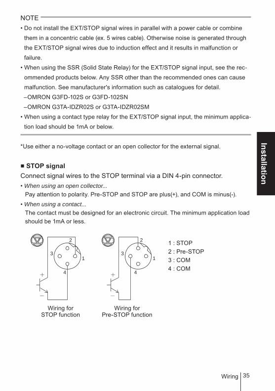
*Use either a no-voltage contact or an open collector for the external signal.
■ STOP signalConnect signal wires to the STOP terminal via a DIN 4-pin connector.• When using an open collector...
Pay attention to polarity. Pre-STOP and STOP are plus(+), and COM is minus(-).
• When using a contact...The contact must be designed for an electronic circuit. The minimum application load should be 1mA or less.
1 : STOP2 : Pre-STOP3 : COM4 : COM
Wiring forSTOP function
3
2
4
13
2
4
1
Wiring forPre-STOP function
Wiring
36
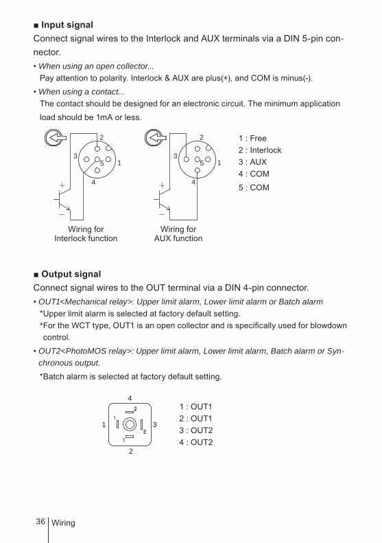
■ Input signalConnect signal wires to the Interlock and AUX terminals via a DIN 5-pin con-nector.• When using an open collector...
Pay attention to polarity. Interlock & AUX are plus(+), and COM is minus(-).
• When using a contact...The contact should be designed for an electronic circuit. The minimum application
load should be 1mA or less.
1 : Free2 : Interlock3 : AUX4 : COM
5 : COM
■ Output signalConnect signal wires to the OUT terminal via a DIN 4-pin connector.• OUT1<Mechanical relay>: Upper limit alarm, Lower limit alarm or Batch alarm
*Upper limit alarm is selected at factory default setting.* For the WCT type, OUT1 is an open collector and is specifically used for blowdown control.
• OUT2<PhotoMOS relay>: Upper limit alarm, Lower limit alarm, Batch alarm or Syn-chronous output.
*Batch alarm is selected at factory default setting.
1 : OUT12 : OUT13 : OUT24 : OUT2
3
2
4
5 13
2
4
5 1
Wiring forInterlock function
Wiring forAUX function
1
2
3
4
Wiring

37
InstallationSensor cable connection
Points to be checked• Check that the main power is turned off.
NOTE• Do not wet wire terminals or the terminal box. Keep them free from contamination
such as oil. Contamination impairs insulation and affects readings. Clean with alcohol
and wait until they dry off when they are contaminated.
• Keep the sensor cable away from a motor and its power cable which generate noise.
• Optimise the sensor cable wiring, taking account of calibration, inspection and re-
placement works.
For the WCT, remove the terminal case and pass the sensor cable into the cable path as below.
For the WPO, connect the sensor cable via the BNC connector. Always select "MTC (Manual Temperature Compensation)" in User mode after the connec-tion.
NOTE Tighten the terminal case and cable gland enough to keep sealing performance.
E1E2
T
T
S
CableTerminal case
Cable gland
Wiring

38
■ Terminal boxConnect sensor cable terminals to the terminal box.
* Use spade terminal with the following size.
Optimumterminal size
WEC/WCT typeSee the table below when wiring.
Terminal # Functions1-2 T, T: Temperature compensation3-5 Disused6-7 E1, E2: Conductivity sensor8 Disused9 S: Shield
NOTE• The pH/ORP electrode cable is a high-voltage insulated cable so extra care is re-
quired.
• Always use a specified junction cable when extending or relaying the sensor cable.
The use of conduit pipe to the optional junction cable is recommended for the preven-
tion of the static electricity caused by induction or vibration.
• Be careful not to damage the sensor cable. The sensor signal is a faint electrical
signal.
• Do not extend or modify sensor cable.
6.0m
m o
r bel
ow
3.2m
m
Wiring

39
InstallationMultibox (Relay type)The WCT type needs a Multibox (relay type) when making blowdown control.■ OutlineThe multibox is designed to supply power supply voltage to both the pump and blowdown valve.
SpecificationModel code TK-PC99-6RY
InputPower supply 100-240VAC 50/60HzControl Blowdown control
OutputVoltage contact
Max. 250VAC, 3A (Resistance load)The same voltage as power supply voltage
Pump power supply The same voltage as power supply voltage
Outer dimensions
94
(148)
94
57
79
79
4×ø5
Cable gland
Wiring

40
■ InstallationFix the Multibox.
Necessary tools• Four M4 Phillips screws (Multibox mounting)
Select an installation location.See page 10 and select the best installation location.
NOTEMaintain a space for wiring work.
Open the cover.Unscrew and open the cover.
Fix with Four M4 screws.Unscrewing the cover, there are four through-holes on corners. Fix the multibox through the holes by M4 screws and then mount the cover in the last place.
79
79
4×ø5
1
2
3
Wiring

41
Installation■ WiringSee below for wiring outline.
Cable connectionConnect cables to the Multibox. Follow the instruction below.
Points to be checked• Check that the main power is turned off.
• When using OUT2...Punch out the cover on the CN2 and connect a output cable. Use cable glands to tighten the cable.
TB1
CN1
ESCPower supply100-240VAC
Blowdownvalve
Multibox (Relay type)
Pump
Conductivitysensor
Sensor inputOutput terminal
Pump power
Pump power cable(1950mm)
Use optional DIN connector cable.
Use a triplex cable (ø4.5-ø10).
Use a duplex cable (ø4.5-ø10).
TB2(Power input)
TB2(Relay output)
12
1 2
34
TB1
CN1
CN2
TB2
ONOFF
12
34
CN1
TB1
OUT2
OUT1OUT2 terminal
Black
Blue
White
Brown
Pump power supply cable
Pump output cable
Blowdown controloutput
*Provide a spade terminal to the earth wire.
Earth wire
Wiring

42
Connection for power supply and a blowdown valve
NOTETighten cable glands securely to maintain sealing performance.
Switch ONSwitch on the Multibox and close the cover after wiring work. The system is now ready for blowdown control.
NOTEClose the cover tight to maintain sealing performance.
12
34
TB1
CN1
TB2
ONOFF
TB2
Powersupply
Blowdownvalve
Earthing
N/ON/C
100-240VAC50/60Hz
* Select N/O or N/C along with the specification of the blowdown valve.
* Use spade terminal(Y3 or equivalent) for con-nection. See page 38 for dimension.).
Switch
Wiring

43
Operation
Run the pump after pipework and wiring is completed.This section describes pump operation and programming.
Before operation
Check the flow rate, tubing and wiring. And then perform degassing and flow rate adjustment before starting operation.
Points to be checkedBefore operation, check if...• Liquid level in the supply tank is enough.• Tubing is securely connected and is free from leakage and clogging.• Discharge/suction valves are opened.• Proper power voltage is applied to the pump.• Electrical wiring is correct and is free from the risk of short circuit and electri-
cal leakage.
Retightening of pump head fixing bolts
ImportantThe pump head fixing bolts may loosen when plastic parts creep due to tem-perature change in storage or in transit.This can lead to leakage. Retighten the pump head fixing bolts before starting operation.Always tighten the bolts diagonally. See below for the tightening torque at each model.
Tightening torque
Model identification code Torque BoltsEWN-B09•11•16•21 2.16 N•m M4 Hex. socket head boltEWN-B31 2.55 N•m M4 Hex. socket head boltEWN-C16•21 2.16 N•m M4 Hex. socket head boltEWN-C31 2.55 N•m M4 Hex. socket head boltEWN-C36 2.55 N•m M5 Hex. socket head bolt
*Tighten fixing bolts once every three months.
Operation
Before operation

44
■ Use of hexagon wrench instead of a torque wrenchFasten the fixing bolts as tight as can be by the hand with the straight long part of a hexagon wrench (a) and further turn the bolts clockwise 90 degrees with the short part (b).
DegassingThe gas needs to be expelled from the pump and tubing by degassing. Normal performance can not be obtained with gas in the pump. Conduct degassing in the following cases.
• When the pump starts to run for the first time• When the flow rate is too low• After liquid is replaced in the supply tank• After a long period of stoppage• After maintenance and inspection
NOTE• Both gas and chemical come out together through air bleed tube. Place the end of the
tube in the supply tank or another container.
• Some chemicals may cause skin trouble or damage component parts. When your
hand or component parts get wet with chemical liquid, wipe off immediately.
Straight longpart
Short part
a b
90°
Before operation

45
Operation
Points to be checked• An air bleed tube is connected to the pump.
Turn on power.The ON LED lights and a display re-lated to the current mode appears on the screen.* The pump enters the wait state in the AUTO mode when turning on power with a default setting. The pump calls up the last screen at a shutoff if it was not in a
default setting.
NOTEThe screen shows "ERR7" when input signal wires are not connected. Complete connection and then turn on power.
Run the pump at the maximum stroke rate.Select a convenient way from the following.• Set the stroke rate to 100% and run the pump manually.
* Select manual operation in the user mode. The pump runs or stops as the start/stop key is pressed. See page 61 for detail.
Air bleed tube
ON LED
2
1
ESC ESC
Before operation

46
• Enter the external signal via the AUX terminals.
• Press and hold both the UP and DOWN keys.
Rotate the adjusting screw two revolutions anticlockwise to open the air vent port.* Do not rotate it three revolutions. Otherwise, liquid may comes out from the air vent port.
Keep the pump running for more than ten minutes for degassing.
Stop the pump by...• pushing the start/stop key once or• stopping the AUX signal or• releasing the UP and DOWN keys
4
5
AUX signalinput
ESC ESC
ESC ESC
Adjusting screw3
Before operation
47
Operation
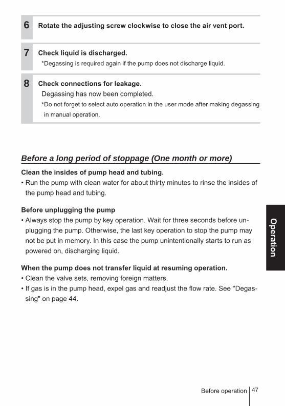
Rotate the adjusting screw clockwise to close the air vent port.
Check liquid is discharged.*Degassing is required again if the pump does not discharge liquid.
Check connections for leakage.Degassing has now been completed.* Do not forget to select auto operation in the user mode after making degassing
in manual operation.
Before a long period of stoppage (One month or more)Clean the insides of pump head and tubing.• Run the pump with clean water for about thirty minutes to rinse the insides of
the pump head and tubing.
Before unplugging the pump• Always stop the pump by key operation. Wait for three seconds before un-
plugging the pump. Otherwise, the last key operation to stop the pump may not be put in memory. In this case the pump unintentionally starts to run as powered on, discharging liquid.
When the pump does not transfer liquid at resuming operation.• Clean the valve sets, removing foreign matters.• If gas is in the pump head, expel gas and readjust the flow rate. See "Degas-
sing" on page 44.
6
7
8
Before operation

48 Operation programming
Operation programming
The pump operation is programmed and controlled by a control unit.The pump is controlled in different ways at each operation mode.
Default setting and setting rangeParameters Setting ranges STEP*1 Default
Mode selection - AUTO or MAN - AUTO
Control
WPO WEC
1PtWPO
PH : 0.00 - 14.00 0.01 8.60
ORP : -2000 - 2000 1 200
WEC : 0 - 400 1 200
1Pt stroke rate 1 - MAX (spm) 1 0
2PtWPO
PH : 0.00 - 14.00 0.01 14.00
ORP : -2000 - 2000 1 1200
WEC : 0 - 400 1 0
2Pt stroke rate 1 - MAX (spm) 1 MAX
Integral 0 - 100.0 (s) 0.1 0.0
Derivative 0 - 100.0 (s) 0.1 0.0
WCT
Starting point 0 - 399 1 200
Stop point 0 - 399 1 100
Stroke rate range 1 - MAX (spm) 1 MAX
Pump control INT or B.SYC - INT
ON time 00 : 01 - 23 : 59 (HH : MM) 00 : 01 01 : 00
OFF time 00 : 01 - 23 : 59 (HH : MM) 00 : 01 02 : 00
Lock out time 00 : 00 - 99 : 59 (MM : SS) 00 : 01 40 : 00
Time limit 00 : 00 - 99 : 59 (MM : SS) 00 : 01 20 : 00
Measurement
WPO PH/ORP selection PH or ORP - PH
WPO (PH)
PH buffer selection NIST (4.7.9) / NIST (2.7.9) / TECH - NIST(4.7.9)
Auto/Man selection AUTO or MAN - AUTO
WPO WECWCT
Measured value adjustment
WPOPH mode : -2.00 - 2.00 0.01 0.00
ORP mode : -200 - 200 1 0
WEC/WCT : -100 - 100 1 0
WPO (PH) WEC
Auto/Man TC selection AUTO or MAN - AUTO
Temperature adjustment(When Auto TC is
selected)-10.0 - 10.0 0.1 0.0
WPO WEC
Temperature setting(Man TC)
WPO: 0.0 - 99.00.1 25.0
WEC: 0.0 - 50.0
49
Operation
Operation programming
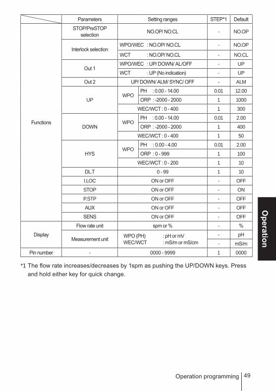
Parameters Setting ranges STEP*1 Default
Functions
STOP/PreSTOPselection NO.OP/ NO.CL - NO.OP
Interlock selectionWPO/WEC : NO.OP/ NO.CL - NO.OP
WCT : NO.OP/ NO.CL - NO.CL
Out 1WPO/WEC : UP/ DOWN/ AL/OFF - UP
WCT : UP (No indication) - UP
Out 2 UP/ DOWN/ ALM/ SYNC/ OFF - ALM
UPWPO
PH : 0.00 - 14.00 0.01 12.00
ORP : -2000 - 2000 1 1000
WEC/WCT : 0 - 400 1 300
DOWNWPO
PH : 0.00 - 14.00 0.01 2.00
ORP : -2000 - 2000 1 400
WEC/WCT : 0 - 400 1 50
HYSWPO
PH : 0.00 - 4.00 0.01 2.00
ORP : 0 - 999 1 100
WEC/WCT : 0 - 200 1 10
DL.T 0 - 99 1 10
I.LOC ON or OFF - OFF
STOP ON or OFF - ON
P.STP ON or OFF - OFF
AUX ON or OFF - OFF
SENS ON or OFF - OFF
Display
Flow rate unit spm or % - %
Measurement unit WPO (PH) : pH or mV WEC/WCT : mS/m or mS/cm
- pH
- mS/m
Pin number - 0000 - 9999 1 0000
*1 The flow rate increases/decreases by 1spm as pushing the UP/DOWN keys. Press and hold either key for quick change.
50 Operation programming
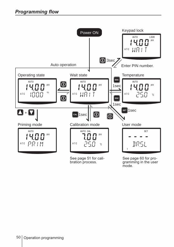
Programming flow
Power ON
Auto operation
Operating state Wait state Temperature
User modeCalibration mode
Keypad lock
Enter PIN number.3sec
1sec
1sec
1sec
Priming mode
1sec+
See page 51 for cali-bration process.
See page 60 for pro-gramming in the user mode.

51
Operation
Operation programming
Perform a calibrationBefore calibration, program measurement conditions in the user mode. See page 64 for detail. And then enter the calibration mode and calibrate this prod-uct at each measuring object.
NOTEElectrodes or sensors to be used and calibration process vary with a measuring object.
• Calibration for pH measurement (WPO type)...Auto 1Pt or 2Pt calibration and Man 1Pt or 2Pt calibration are available.
• Calibration for ORP measurement (WPO type)...A sensitivity check and a Man calibration is available.
• Calibration for conductivity measurement (WEC/WCT types)...Cell constant programming and measured value calibration is available.
■ Use of a conductivity sensor• See the wiring section for connection. Always program the cell constant value tags
along each sensor.
• Do not extend or shorten the sensor cable. A cell constant may change and an error may occur.
• Unscrew the top cover and rinse with tap water when cleaning. Use a neutral deter-gent with a soft close as necessary.
52 Operation programming
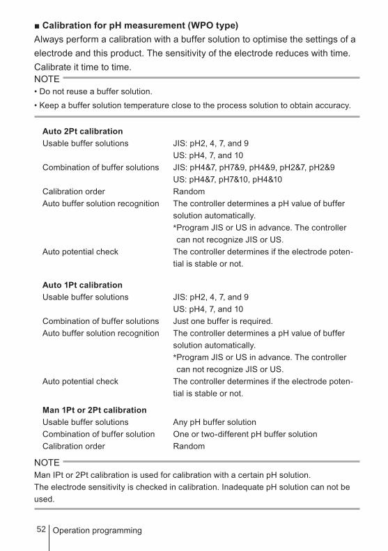
■ Calibration for pH measurement (WPO type)Always perform a calibration with a buffer solution to optimise the settings of a electrode and this product. The sensitivity of the electrode reduces with time. Calibrate it time to time.NOTE• Do not reuse a buffer solution.
• Keep a buffer solution temperature close to the process solution to obtain accuracy.
Auto 2Pt calibrationUsable buffer solutions JIS: pH2, 4, 7, and 9 US: pH4, 7, and 10Combination of buffer solutions JIS: pH4&7, pH7&9, pH4&9, pH2&7, pH2&9 US: pH4&7, pH7&10, pH4&10Calibration order RandomAuto buffer solution recognition The controller determines a pH value of buffer
solution automatically. * Program JIS or US in advance. The controller
can not recognize JIS or US.Auto potential check The controller determines if the electrode poten-
tial is stable or not.
Auto 1Pt calibrationUsable buffer solutions JIS: pH2, 4, 7, and 9 US: pH4, 7, and 10Combination of buffer solutions Just one buffer is required.Auto buffer solution recognition The controller determines a pH value of buffer
solution automatically. * Program JIS or US in advance. The controller
can not recognize JIS or US.Auto potential check The controller determines if the electrode poten-
tial is stable or not.
Man 1Pt or 2Pt calibrationUsable buffer solutions Any pH buffer solutionCombination of buffer solution One or two-different pH buffer solutionCalibration order Random
NOTEMan IPt or 2Pt calibration is used for calibration with a certain pH solution.The electrode sensitivity is checked in calibration. Inadequate pH solution can not be used.

53
Operation
Operation programming
■ Auto calibration1Pt or 2Pt calibration can be performed as immersing an electrode in buffer solution and pushing the CAL key.
Press and hold the CAL key for one second to enter the Cal mode. Immerse the electrode into a buffer solution. Keep a certain distance from a tank bottom and sidewalls.
Push the CAL key once for 1Pt calibration.The measured pH flushes. If "HOLD" is shown on the screen as blinking stops, the 1Pt calibration has finished.If the 2Pt calibration is not required, push the start/stop key once to return to the wait state.
Push the CAL key once for 2Pt calibration. Immerse the electrode into the next buffer solution. The measured pH flashes. If "HOLD" is shown on the screen as blinking stops, the 2Pt calibration has finished.Push the start/stop key once to return to the wait state.
2
1
3
ESC
ESC ESC
ESC ESC
54 Operation programming
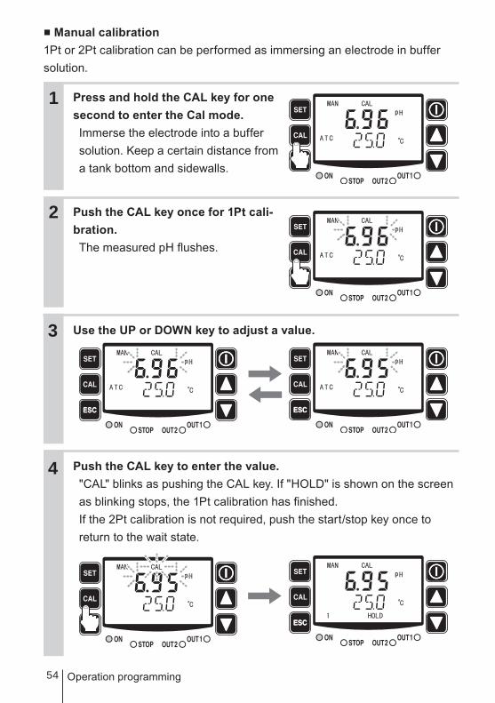
■ Manual calibration1Pt or 2Pt calibration can be performed as immersing an electrode in buffer solution.
Press and hold the CAL key for one second to enter the Cal mode. Immerse the electrode into a buffer solution. Keep a certain distance from a tank bottom and sidewalls.
Push the CAL key once for 1Pt cali-bration.The measured pH flushes.
Use the UP or DOWN key to adjust a value.
Push the CAL key to enter the value."CAL" blinks as pushing the CAL key. If "HOLD" is shown on the screen as blinking stops, the 1Pt calibration has finished.If the 2Pt calibration is not required, push the start/stop key once to return to the wait state.
2
1
3
ESC
ESC
ESC ESC
ESC ESC
4

55
Operation
Operation programming
Push the CAL key once for 2Pt calibration. Immerse the electrode into the next buffer solution.
Push the CAL key again.A measured value starts flashing.
Use the UP or DOWN key to adjust a value.
Push the CAL key to enter the value.If "HOLD" is shown on the screen as blinking stops, the 2Pt calibration has finished.Push the start/stop key once to return to the wait state.
5
6
ESC ESC
ESC ESC
ESC ESC
ESC ESC
7
8

56 Operation programming
■ Calibration for ORP measurement (WPO type)The calibration for ORP measurement is effective on the following.• Sensitivity check by ORP
Electrode sensitivity is checked if correct or not.
• Man calibrationReadings are corrected to the actual process value.
Sensitivity check process by ORPNOTEIn this process, the electrode is checked for its sensitivity. This process is different from
the pH electrode sensitivity check that correct reading errors on the controller.
a. Prepare a ORP buffer solution* mV in the buffer solution starts to reduced two hours after preparation (dissolving of ORP powders). First use is recommended. Do not preserve the buffer solution.
b. Dissolve ORP powders in 500ml of pure water.c. Immerse the electrode into the solution.d. Check the solution temperature is in between 10 and 30°C.e. Check if mV is in the allowable range below.
When using a saturated calomel reference electrode: 220±20mVWhen using a silver chloride reference electrode: 260±20mV
If the mV is out of the allowable range, take the steps below.a. Remove contamination with a gauze.b. Polish a metal pole carefully with a sandpaper of about #1000.c. Immerse the electrode into dilute nitric acid (1:1) and then rinse with pure
water.Check if the mV is in the allowable range. If it is still out of range, replace the electrode.
f. Replace the electrode from the solution.g. Rinse and wipe off the electrode.

57
Operation
Operation programming
■ MAN calibrationThis process is different from the pH electrode sensitivity check that correct reading errors on the controller, and the actual conductivity and mV reading will not be the same.In this process, a reading range only is adjusted and 0mV is fixed.
Press and hold the CAL key for one second to enter the Cal mode. Immerse the electrode into a buffer solution.
Use the UP or DOWN key to adjust a value. The bottom line will display a reading range (Default value is 100.0% ). The settable range is 80.0 - 120.0%.
Push the CAL key to enter the value.
Push the start/stop key once to return to the wait state.Once a value is entered, the bottom line displays "1" on the left hand side. "1" will disappear if the default range is entered.
2
1
3
4
ESC
ESC ESC
ESC ESC
ESC ESC

58 Operation programming
■ Conductivity calibration (WEC/WCT)The following two are to be calibrated.• Cell constant
• ReadingCell constant
Press and hold the CAL key for one second to enter the Cal mode.
Push the CAL key again.
Use the UP or DOWN key to adjust a value.The setting range is 0.80 - 1.20.
Push the CAL key to enter the value.If "HOLD" is shown on the screen, the cell constant setting has finished.Push the start/stop key once to return to the wait state.
2
1
3
4
ESC
ESC ESC
ESC ESC
ESC ESC
59
Operation
Operation programming
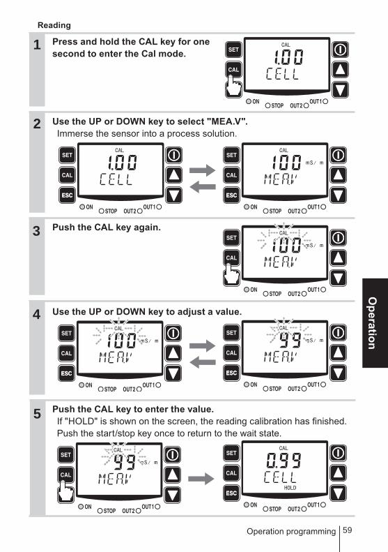
Reading
Press and hold the CAL key for one second to enter the Cal mode.
Use the UP or DOWN key to select "MEA.V".Immerse the sensor into a process solution.
Push the CAL key again.
Use the UP or DOWN key to adjust a value.
Push the CAL key to enter the value.If "HOLD" is shown on the screen, the reading calibration has finished.Push the start/stop key once to return to the wait state.
2
1
3
4
ESC
ESC
ESC ESC
ESC ESC
ESC ESC
5

60 Operation programming
User modePress and hold the SET key for one second in the wait state (the bottom line displays "WAIT".). The pump enters the User mode. Push the start/stop key when returning to the wait start.■ User mode menu selection Use the UP and DOWN keys to scroll through menus and select with the SET key.
AUTO/MAN selectionSelect AUTO or MAN operation. See page 61 for detail.
Control parameter programmingProgram control parameters. See pate 62 for detail.
Measurement parameter programmingProgram measurement parameters. See page 64 for detail.
Function programmingProgram input/output parameters. See page 67for detail.
Display selectionSelect spm indication or a measurement unit.See page 73 for detail.
Pin number entryProgram pin number for release keypad lockfunction. See page 74 for detail.

61
Operation
Operation programming
■ AUTO/MAN selectionSelect AUTO or MAN operation.
Menu selection
AUTO/MAN selection
AUTO operation MAN operation
Use keys

62
Menu selectionControl parameter programming
Use keysto enter value.
Use keys to scroll thorough menus.
DerivativeEnter a derivative (sec)
Process valueat SP.1Enter aprocess value.
SPM at SP.1Enter spm.
Process value at SP.2Enter a process value.
SPM at SP.2Enter spm.
IntegralEnter an integral (sec)
Enter process values and spm at SP.1 and SP.2 for proportional control.
Enter an integral and a derivative for PID control.
Operation programming
■ Control parameter programmingProgram control parameters.• WPO/WEC types
Programming for Proportional control and PID control

63
Operation
Operation programming
• WCT typeProgramming for blowdown control
Menu selectionControl parameter programming
Use keysto enter value.
Use keys to scroll thorough menus.
Starting pointEnter a processvalue to startblowdown control.
These menus appear when INT is selected.
Stop pointEnter a process value to stopblowdown control.
SPM settingProgram a spm that the pumpruns at.
INT or b.SYCSelect intermittent or blow syncoperation.
ON time settingProgram on time in INT operation.
OFF time settingProgram off time in INT operation.
Lockout time settingProgram delay time of pumpoperation in blow sync operation.
Time limit settingProgram the maximum timefor the pump to run.
These menus appear when b.syc is selected.

64 Operation programming
■ Measurement parameter programmingProgram measurement parameters.
Menu selection
Use keys to scroll thorough menus.
pH/ORP selection (WPO type)Select pH or ORP.See page 65 for detail.
pH buffer selection (WPO type)Select a pH buffer type forthe automatic calibration.See page 65 for detail.
AUTO/MAN pH calibrationselection (WPO type)Select AUTO or MAN pH calibration.See page 65 for detail.
Measured value adjustmentAdjust measured values.See page 66 for detail.
AUTO/MAN TC selection(WPO with pH/WEC/WCT types)Select AUTO or MAN temperaturecompensation.See page 66 for detail.
Temperature reading adjustment/Temperature setting(WPO with pH/WEC/WCT types)Adjust temperature in AUTOtemperature compensation.Program temperature in MANtemperature compensation.See page 66 for detail.

65
Operation
• pH/ORP selection
• pH buffer selection (WPO type)
• AUTO/MAN pH calibration (WPO type)
Operation programming
Use keys to change menus.
pH mode ORP mode
pH4.7.9(JIS) pH2.7.9(JIS) pH4.7.10(US)
Use keys to change menus.
AUTO MAN
Use keys to change menus.

66
• Measured value adjustment
• AUTO/MAN TC selection (WPO with pH/WCT types)
• Temperature reading adjustment (WPO with pH/WEC/WCT types) in AUTO TC
• Temperature setting (WPO with pH/WEC/WCT types) in MAN TC
Operation programming
Use keys to changevalues.*Setting range changeswith measuring object.WPO PH: -2.00 - 2.00pHWPO ORP: -200 - 200mVWEC/WCT: -100 - 100mS/m
AUTO MAN
Use keys to change menus.
Use keys to changevalues.*Setting range is-10.0 - 10.0ºC
Use keys to changevalues.*Setting range is0.0 - 99.0ºC.

67
Operation
Operation programming
■ Function programmingProgram input/output parameters.
OUT1settingmenu
Menu selectionSTOP functionProgram ON-OFF operation viathe STOP signal. See page 68.
Use keys to scroll thorough menus.
Interlock functionProgram ON-OFF operation viathe interlock signal. See page 68.
OUT1Program alarm output.See page 69.
Programing menus will be addeddepending on OUT1 setting.
OUT2Program alarm and synchronousoutputs. See page 69.
Programing menus will be addeddepending on OUT2 setting.
OUT2settingmenu
68 Operation programming
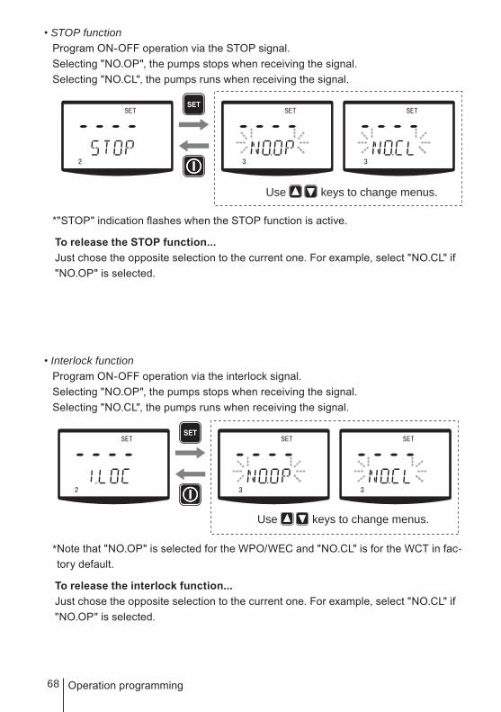
• STOP functionProgram ON-OFF operation via the STOP signal.Selecting "NO.OP", the pumps stops when receiving the signal.Selecting "NO.CL", the pumps runs when receiving the signal.
*"STOP" indication flashes when the STOP function is active.
To release the STOP function...Just chose the opposite selection to the current one. For example, select "NO.CL" if "NO.OP" is selected.
• Interlock functionProgram ON-OFF operation via the interlock signal.Selecting "NO.OP", the pumps stops when receiving the signal.Selecting "NO.CL", the pumps runs when receiving the signal.
* Note that "NO.OP" is selected for the WPO/WEC and "NO.CL" is for the WCT in fac-tory default.
To release the interlock function...Just chose the opposite selection to the current one. For example, select "NO.CL" if "NO.OP" is selected.
Use keys to change menus.
Use keys to change menus.
69
Operation
Operation programming
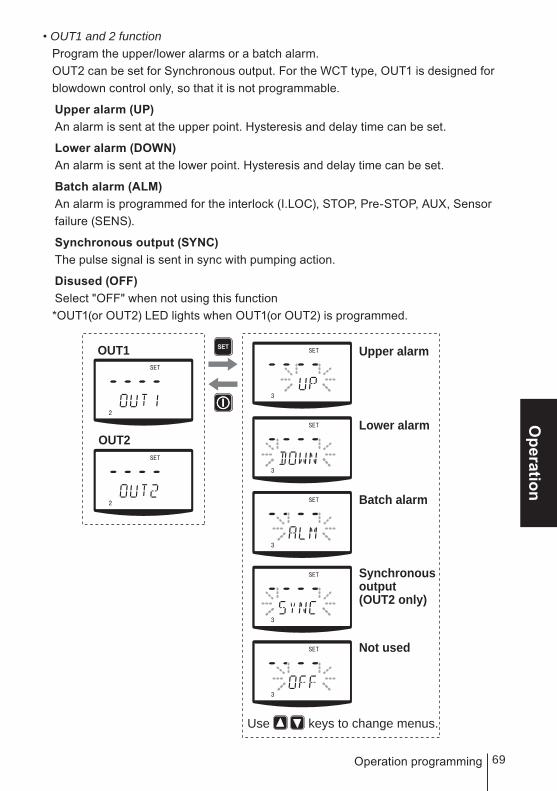
• OUT1 and 2 functionProgram the upper/lower alarms or a batch alarm.OUT2 can be set for Synchronous output. For the WCT type, OUT1 is designed for blowdown control only, so that it is not programmable.
Upper alarm (UP)An alarm is sent at the upper point. Hysteresis and delay time can be set.
Lower alarm (DOWN)An alarm is sent at the lower point. Hysteresis and delay time can be set.
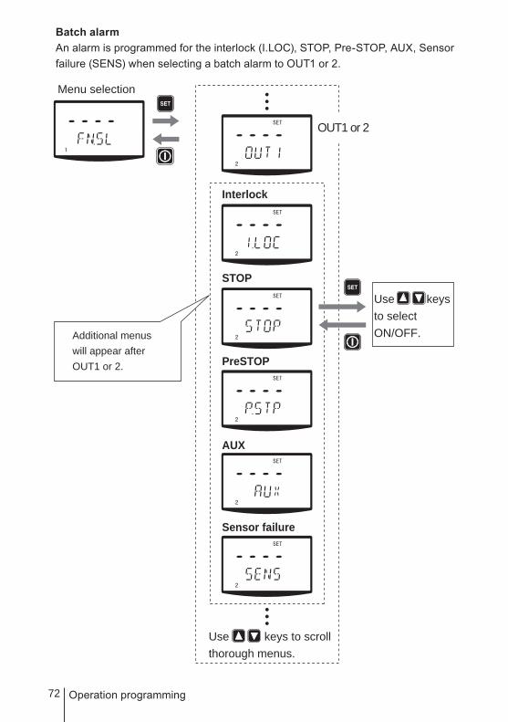
Batch alarm (ALM)An alarm is programmed for the interlock (I.LOC), STOP, Pre-STOP, AUX, Sensor failure (SENS).
Synchronous output (SYNC)The pulse signal is sent in sync with pumping action.
Disused (OFF)Select "OFF" when not using this function*OUT1(or OUT2) LED lights when OUT1(or OUT2) is programmed.
Upper alarm
Lower alarm
Use keys to change menus.
Batch alarm
Synchronousoutput(OUT2 only)
Not used
OUT1
OUT2

70 Operation programming
• Upper alarm, lower alarm and batch alarm programmingProgram each alarm individually.
Upper alarmProgram the upper limit, hysteresis and delay time when selecting an upper alarm to OUT1 or 2.
Menu selection
OUT1 or 2
Use keys to scrollthorough menus.
Use keysto enter value.
Additional menus will appear after OUT1 or 2.
Upper limit
Hysteresis
Delay time

71
Operation
Operation programming
Lower alarmProgram the lower limit, hysteresis and delay time when selecting an upper alarm to OUT1 or 2.
Menu selection
OUT1 or 2
Use keys to scrollthorough menus.
Use keysto enter value.
Additional menus will appear after OUT1 or 2.
Lower limit
Hysteresis
Delay time
72 Operation programming
Batch alarmAn alarm is programmed for the interlock (I.LOC), STOP, Pre-STOP, AUX, Sensor failure (SENS) when selecting a batch alarm to OUT1 or 2.
Menu selection
OUT1 or 2
Use keys to scrollthorough menus.
Use keysto selectON/OFF.Additional menus
will appear after OUT1 or 2.
Interlock
STOP
PreSTOP
AUX
Sensor failure

73
Operation
Operation programming
■ Display selectionSelect spm indication or a measurement unit.
When selecting a stroke rate...Chose spm or %.
When selecting a measured value...Chose pH or mV for the WPO in pH mode orChose mS/m or mS/cm for the WEC/WCT types.
Use keys to scrollthorough menus.
Use keysto chagne units.
Stroke rate
Measured value
74 Operation programming
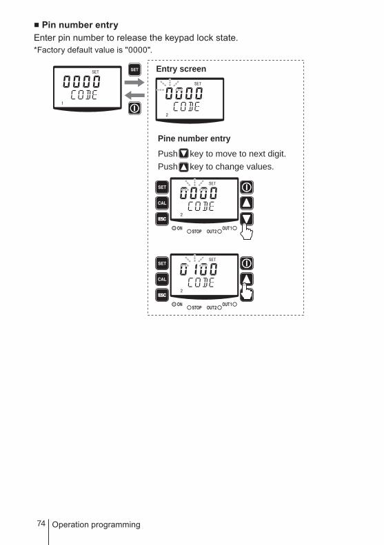
■ Pin number entryEnter pin number to release the keypad lock state.*Factory default value is "0000".
ESC
ESC
Entry screen
Pine number entry
Push key to move to next digit.Push key to change values.

75
Operation
Operation
Operation
Read this section before operation.
AUTO operationThe pump monitors and controls process solution automatically.
Turn on power.The ON LED lights and a display related to the current mode appears on the screen.* The pump enters the wait state in the
manual mode when turning on power with
a default setting. The pump calls up the last
screen at a shutoff if it was not in a default
setting.
Check that the pump is in AUTO mode.* If the screen displays "MAN", it means the
pump is in manual mode. In this case select
"AUTO" in the user mode. See page 61 for
detail.
Push the start/stop key to stay readyThe ON LED lights greenly and the pump starts control automatically.
2
1
ON LED
ESC
ESC ESC
3
76 Operation
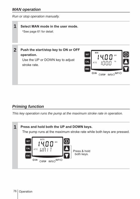
MAN operationRun or stop operation manually.
Select MAN mode in the user mode.* See page 61 for detail.
Push the start/stop key to ON or OFF operation.Use the UP or DOWN key to adjust stroke rate.
Priming functionThis key operation runs the pump at the maximum stroke rate in operation.
Press and hold both the UP and DOWN keys.The pump runs at the maximum stroke rate while both keys are pressed.
ESC
1
1
2
Press & hold both keys.
77
Operation
Operation
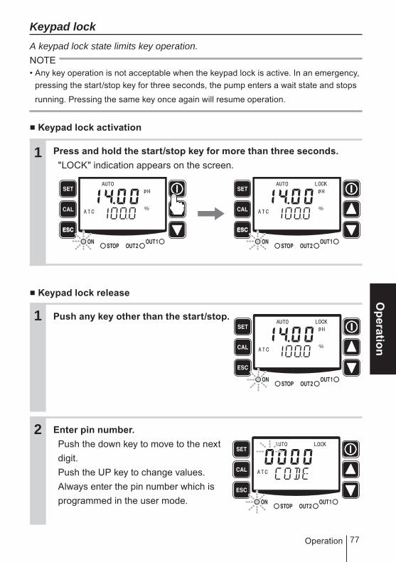
Keypad lockA keypad lock state limits key operation.NOTE• Any key operation is not acceptable when the keypad lock is active. In an emergency,
pressing the start/stop key for three seconds, the pump enters a wait state and stops
running. Pressing the same key once again will resume operation.
■ Keypad lock activation
Press and hold the start/stop key for more than three seconds."LOCK" indication appears on the screen.
■ Keypad lock release
Push any key other than the start/stop.
Enter pin number.Push the down key to move to the next digit.Push the UP key to change values.Always enter the pin number which is programmed in the user mode.
ESC ESC
1
2
1

78 Operation
Push the SET keyThe keypad lock state then will be released.* If the pin number is not correct, "FAIL" will be shown and the lock state will
remain.
■ Operation stop with a keypad lock state
Press and hold the start/stop key for three seconds.The pump enters a wait state and stops running in the keypad lock state. Pressing the same key once again will resume operation with keypad lock active.
ESC ESC
ESC
1
3

79
Maintenance
MaintenanceThis section describes troubleshooting, electrode/sensor main-tenance, wear part replacement, exploded views and specifi-cations.
Important• Observe instructions in this manual for maintenance, inspection, disman-
tlement and assembly. Do not dismantle the pump beyond the extent of the instructions.
• Always wear protective clothing such as an eye protection, chemical resistant gloves, a mask and a work cap during dismantlement, assembly or maintenance work.
• Be sure to turn off power to stop the pump and related devices before work. See below.
Before unplugging the pumpAlways stop the pump by key operation. And wait for three seconds before unplugging the pump. Otherwise, the last key operation to stop the pump may not be put in memory. In this case the pump unintentionally starts to run as powered on, discharging liquid.
NOTE
• We do not assure material suitability in a specified application and are not responsible
for any failure due to corrosion or erosion.
• Contact us or your nearest dealer for repair or contact a manufacturer of the host
machine which our product is built in.
• Be sure to drain chemicals and clean the inside of the pump before return so that a
harmful chemical does not spill out in transit.
Maintenance

80
Troubleshooting
First check the following points. If the following measures do not help removing problems, contact us or your nearest dealer.
■ PumpStates Possible causes Solutions
The pump does not run. (LED does not appear. Blank screen.)
Power voltage is too low. • Recover the power voltage to a nor-mal level. Allowable voltage range: 90-264VAC
The pump is not powered. • Check the switch if it is installed.• Correct wiring• Replace a breaking wire to new one.
Liquid can not be sucked up.
Air lock in the pump • Expel air. See page 44.
Stroke length is too short. • Run the pump at 100% stroke length and adjust it to proper length.
Air ingress through suction line. • Correct tubing.
A valve set is installed upside down. • Reinstall the valve set.
Valve gaskets are not installed. • Install valve gaskets.
Foreign matters are stuck in the pump head valves.
• Dismantle, inspect and clean the valve. Replace as necessary.
A ball valve is stuck on a valve seat. • Dismantle, inspect and clean the valve. Replace as necessary.
The flow rate fluctuates.
Air stays in the pump head. • Expel air. See page 44.
Overfeeding occurs. • Mount a check valve. See page 28.
Foreign matters are stuck in the pump head valves.
• Dismantle, inspect and clean the valve. Replace as necessary.
Diaphragm is broken. • Replace the diaphragm. See page 92.
Pressure fluctuates at an injection point.
• Review tubing layout to maintain a pressure constant at an injection point or change an injection point in a constant pressure.
Liquid leaks. Loose fit of the fitting or the air vent body.
• Retighten them.
Loose fit of the pump head. • Retighten the pump head. See page 43.
O rings or valve gaskets are not in-stalled.
• Install O rings and valve gaskets.
Diaphragm is broken. • Replace the diaphragm. See page 92.
Excessive discharge pressure. • Check that a discharge line is not closed.
• Check if tubing is not clogged.
Troubleshooting

81
Maintenance
Troubleshooting
■ Electrode/SensorWPO type
States Possible causes Solutions
Reading fluc-tuates
Air bubbles are trapped within the sens-ing area.
• Position the electrode such that air bubbles will not be trapped and a flow is sufficient.
A liquid level fluctuates. • Mount the sensor below the minimum liquid level.
A electrode signal wire is laid on close to other cables.
• Keep it away from other cables or pass it into a conduit.
Power noise affects a reading. • Optimise power line or install a noise cut transformer.
The elec-trode is not responding to changes.
Contamination on a probe • Clean the probe.
A scratched or damaged probe • Replace the electrode.
Reading failure
Contamination on a probe • Clean the probe.
An electrode is in air. • Mount the sensor below the minimum solution level.
A scratched or damaged probe, or life end.
• Replace the electrode as necessary.
Wiring failure • Check wiring of G(M) and R wires for the pH sensor. Replace as necessary.
Sensor cable connection is loose or disconnected.
• Secure the connection.
Poor calibration • Perform calibration again. See page 51.
A prove is covered with a protective cap.
• Remove the cap.
A glass membrane stays dry in air. • A dry glass membrane reduces re-sponsivity. Immerse it into pure water for 24 hours and then calibrate it with a buffer.
Sample liquid temperature and buffer solution temperature is much different.
Wait until TC on the electrode becomes stable. See page 51.
A glass membrane is broken. • Replace as necessary.
Internal liquid failure. • Check the internal liquid.

82
WEC/WCT typeStates Possible causes Solutions
Reading fluc-tuates
Air bubbles are trapped within the sens-ing area.
• Position the sensor such that air bub-bles will not be trapped and a flow is sufficient. See page 30.
A liquid level fluctuates.The distance of 30mm from the all sides is not maintained for the sensor.
• Mount the sensor below the minimum liquid level.
• Keep the distance. See page 30.
A sensor signal wire is laid on close to other cables.
• Keep it away from other cables or pass it into a conduit.
Power noise affects a reading. • Optimise power line or install a noise cut transformer.
The sen-sor is not responding to changes.
Contamination on a probe • Clean the probe. See page 86.
A scratched or damaged probe • Replace the sensor.
Reading failure
Contamination on a probe • Clean the probe. See page 86.
An sensor is in air.The distance of 30mm from the all sides is not maintained for the sensor.
• Mount the sensor below the minimum solution level.
• Keep the distance. See page 30.
A scratched or damaged probe, or life end.
• Replace the sensor as necessary.
Wiring failure • Check wiring of G(M) and R wires for the pH sensor. Replace as necessary.
Sensor cable connection is loose or disconnected.
• Secure the connection.
Cell constant failure • Check the cell constant of the sensor. See page 58.
Blowdown control is upset.
A starting or stop point is improper. • Correct each point. See page 63.
Troubleshooting

83
Maintenance
Error codes
Error codes will be shown when this product is in a faulty condition. See below for the meanings of error codes and countermeasures.■ Error code informationWPO type
Error code Possible cause Description Error message is shown in...
Hi* Out of a measurement range A reading is more than pH14.0 or 2000mV. Measurement
Lo* Out of a measurement range A reading is lower than pH0.00 or -2000mV.
ERR2 Response speed anomaly Slow response speed of the pH electrode Calibration
ERR3 Asymmetry potential anomaly Asymmetry potential at pH7 buffer solution is not correct.
ERR4 Electrode sensitivity anomaly pH electrode sensitivity is reduced.
ERR5 Buffer solution anomaly Unspecified buffer solution is used.
ERR6 Calibration failure Calibration is done at the 3Pt.
ERR7
Temperature sensor anomaly • Sensor wire is disconnected or short-circuited.
• Liquid temperature is 99.1°C or above or -0.1°C or below.
Measurement or calibration
ERR8 Setting error The same value is set to setting points. Setting
* In ORP mode only these error codes appear.
WEC/WCT type
Error code Possible cause Description Error message is shown in...
Hi Out of a measurement range A reading is more than 401mS/m. Measurement
Lo Out of a measurement range A reading is lower than 0mS/m.
ERR7
Temperature sensor anomaly • Sensor wire is disconnected or short-circuited.
• Liquid temperature is 99.1°C or above or -0.1°C or below.
Measurement or calibration
ERR8
Setting error • When a stop point is at or above a starting point in upper limit control.
• When a stop point is at or below a start-ing point in lower limit control.
• When the total ON-OFF time exceeds 23:59.*
• When ON or OFF time is set to 0:00.*
Setting
ERR9 Temperature error Liquid temperature is beyond0.0-50.1°C Measurement
* These conditions are possible only for the WCT type.
Error codes

84
■ CountermeasuresWPO type
Error code Possible cause Counter measures
Hi*Out of a measure-
ment rangeLo*
Out of a measure-ment range
• Is the electrode is in a liquid?
• Is the protective cap removed from the measuring surface?
• Is electrode wire connection proper? Pay extra attention to check if the wire G(M) and R is not disconnected.
• Is junction cable is connected properly?
• Study your system so that the elec-trode is always in the liquid at any liquid level.
• Remove the protective cap.
• Check the terminal box on the controller and multibox to see if connection is correct and secured by screws.
ERR2Response speed
anomaly
• Is the electrode clean?• Has the measuring surface been
kept dry for a long period?
• Is the temperature difference be-tween the measured liquid and buffer solution too wide?
• Clean the electrode.• The responsibility deteriorates once
glass membrane becomes dry. In this case immerse the electrode into pure water for 24 hours and then calibrate it with buffer solution.
• Wait until the temperature sensor comes at liquid temperature and then perform calibration.
ERR3Asymmetry po-tential anomaly
• Is the electrode clean?• Is the measuring surface broken?• Does pH buffer solution not have
problem? Is it fresh? Is pH7 se-lected?
• Clean the electrode.• Replace it if it is broken.• If it is not fresh use new buffer solu-
tion.
ERR4Electrode sensi-
tivity anomaly
• Is electrode clean?• Is the measuring surface broken?
• Clean the electrode.• Replace if it is broken.
ERR5Buffer solution
anomaly
• Is proper buffer solution (JIS: pH4, 7, 9) or (US: pH4, 7, 10) is selected? Check the pH difference between buffer solutions is 2pH.
• Check the electrode to see if...The electrode is contaminated.The measuring surface is broken.Inner solution is deteriorated.
• Use proper buffer solution.
• Clean or replace as necessary.
ERR6Calibration failure
• Calibration is done at the 3rd point. • Perform 1 or 2Pt calibration only.
ERR7Temperature sen-
sor anomaly
• Is the resistance between T-T in proper range?1097Ω at 251000-1385Ω at 0-100
• The sensor cable and junction cable is correct?
• Disconnect electrode connection and measure resistance. If resist-ance is out of the proper range shown left, electrode failure is pos-sible. Replace electrode.
• Check the terminal box on the controller and multibox to see if connection is correct and secured by screws.
ERR8Setting error
• Erroneous setting. • Correct setting.
* In ORP mode only these error codes appear.
Error codes
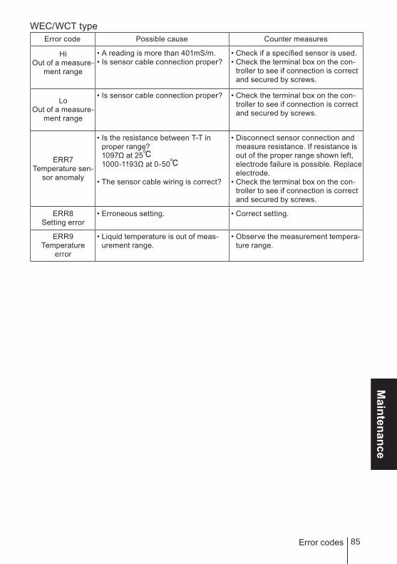
85
Maintenance
WEC/WCT typeError code Possible cause Counter measures
HiOut of a measure-
ment range
• A reading is more than 401mS/m.• Is sensor cable connection proper?
• Check if a specified sensor is used.• Check the terminal box on the con-
troller to see if connection is correct and secured by screws.
LoOut of a measure-
ment range
• Is sensor cable connection proper? • Check the terminal box on the con-troller to see if connection is correct and secured by screws.
ERR7Temperature sen-
sor anomaly
• Is the resistance between T-T in proper range?1097Ω at 251000-1193Ω at 0-50
• The sensor cable wiring is correct?
• Disconnect sensor connection and measure resistance. If resistance is out of the proper range shown left, electrode failure is possible. Replace electrode.
• Check the terminal box on the con-troller to see if connection is correct and secured by screws.
ERR8Setting error
• Erroneous setting. • Correct setting.
ERR9Temperature
error
• Liquid temperature is out of meas-urement range.
• Observe the measurement tempera-ture range.
Error codes

86
Sensor maintenance
Daily inspection
■ Conductivity sensor cleaningContamination on a probe reduces sensitivity. Clean a probe periodically to keep a good sensing condition.• Cleaning process
a. Remove a cover from the probe and flush the sensor with tap water.b. Use neutral detergent to a soft cloth and wipe off contamination. Be careful not to
damage the probe.c. Repeat this process until contamination is removed.
NOTE
A conductivity sensor is wear parts. If there is heavy contamination or damage on a
probe, replace it with new one. Otherwise, reading failure or malfunction may result.
■ PrecautionsClean the conductivity sensor periodically. A best cleaning time is depending on operating conditions. Note that the maximum cleaning frequency is once a month.Always remove the sensor and clean a probe when it is not used. Do not leave it in system.
Sensor maintenance
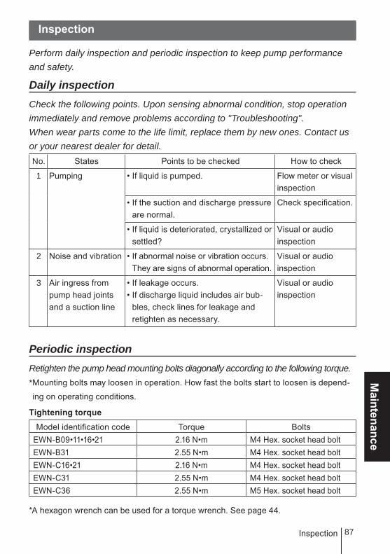
87
Maintenance
Inspection
Inspection
Perform daily inspection and periodic inspection to keep pump performance and safety.
Daily inspectionCheck the following points. Upon sensing abnormal condition, stop operation immediately and remove problems according to "Troubleshooting".When wear parts come to the life limit, replace them by new ones. Contact us or your nearest dealer for detail.No. States Points to be checked How to check
1 Pumping • If liquid is pumped. Flow meter or visual inspection
• If the suction and discharge pressure are normal.
Check specification.
• If liquid is deteriorated, crystallized or settled?
Visual or audio inspection
2 Noise and vibration • If abnormal noise or vibration occurs. They are signs of abnormal operation.
Visual or audio inspection
3 Air ingress from pump head joints and a suction line
• If leakage occurs.• If discharge liquid includes air bub-
bles, check lines for leakage and retighten as necessary.
Visual or audio inspection
Periodic inspectionRetighten the pump head mounting bolts diagonally according to the following torque.* Mounting bolts may loosen in operation. How fast the bolts start to loosen is depend-
ing on operating conditions.
Tightening torque
Model identification code Torque BoltsEWN-B09•11•16•21 2.16 N•m M4 Hex. socket head boltEWN-B31 2.55 N•m M4 Hex. socket head boltEWN-C16•21 2.16 N•m M4 Hex. socket head boltEWN-C31 2.55 N•m M4 Hex. socket head boltEWN-C36 2.55 N•m M5 Hex. socket head bolt
*A hexagon wrench can be used for a torque wrench. See page 44.

88 Wear parts replacement
Wear parts replacement
For a long operation wear parts need to be replaced periodically.It is recommended that the following parts are always stocked for immediate replacement. Contact us or your nearest dealer for detail.
Precautions• When dismantling the pump, pay attention to the residual liquid in the
pump.• Rinse wet ends thoroughly with water.• Each time the pump head is dismantled, replace the diaphragm, O rings,
valve gaskets and valve sets with new ones.
Wear parts list
Parts # of parts Estimated life
Pum
p
Valve set
VC•VH•(PC/PH)-H•TC
2 sets
8000 hours
Diaphragm 1
* The high compression types have a rear diaphragm sheet on the back side of the dia-
phragm.
14
11
1312
11131217
14
11
1312
11131217

89
Maintenance
Wear parts replacement
* Wear part duration varies with the pressure, temperature and characteristics of the
liquid.
* The estimated life is calculated based on the continuous operation with ambient clean
water.
Before replacementFirst release the pressure from the pump.
Stop the pump operation.
Rotate the adjusting screw two revolutions anticlockwise to open the air vent port.NOTEDo not rotate it three revolutions or more. Otherwise, liquid may comes out from
the adjusting screw.
Check that liquid comes out from the air vent port and the internal pressure has been released.NOTEThe internal pressure may not be expelled completely as long as liquid does not
come out. In this case run the pump until the pressure is released.
Valve set replacement■ Discharge valve set dismantlement/assembly
Necessary tools• Adjustable wrench or spanner• 21mm box wrench• A pair of tweezers
*Unfix the pump base before work.
1
2
3

90
Loosen the fitting nut and remove a discharge tube and an air bleed tube.
Turn the lock nut anticlockwise by an adjustable wrench and remove the air vent body A.
Remove the air vent body B by the 21mm box wrench.
Pull out the valve set by a pair of tweezers.
Wear parts replacement
Fitting nutAir bleed tube
Discharge tube
Air vent body B
1
2
3
4
Air ventbody A
Lock nut

91
Maintenance
Suction tube
Fitting nut
Wear parts replacement
Place a new valve set into the pump head. Screw the air vent body B into the pump head through the lock nut.* Be careful not to misarrange the valve set or misplace
upside down. Otherwise, leakage or flow rate reduc-
tion may result.
* Do not forget to fit O rings and gaskets.
* Keep the valve set free from dust or foreign matters.
Remount the air vent body A and connect tubes.
■ Suction valve set dismantlement/assemblyNOTEBe careful not to drop the valve set.
Remove the fitting nut to remove the suction tube.
Remove the fitting by an adjustable wrench or a spanner.
*VC•VH•PC•PH
5
6
Fitting
1
2
Air vent body B
Valve set
Lock nut

92 Wear parts replacement
Pull out the valve set by a pair of tweezers.
Screw the fitting into the pump head with the valve set in it and turn it anticlockwise about 90 degrees by an adjustable wrench or a spanner.* Be careful not to misarrange the valve set or mis-
place upside down. Otherwise, leakage or flow rate
reduction may result.
* Do not forget to fit O rings and gaskets.
* Keep the valve set free from dust or foreign mat-
ters.
Reconnect the suction tube.
Diaphragm replacement
Necessary tools• Adjustable wrench or spanner• Hexagon wrench• Torque wrench
NOTEPay attention not to lose diaphragm spacers. Always apply a proper number of dia-
phragm spacers. 0 or a few diaphragm spacers are inserted between the retainer and
plunger for the adjustment of diaphragm location. Note that the number of diaphragm
spacers varies with pump model. Some pumps may use no spacer.
Valve set
Fitting
*VC•VH•PC•PH
4
5
3

93
Maintenance
Diaphragm
Diaphragm spacer
Retainer
Plunger
Wear parts replacement
Loosen the fitting nuts and remove a suction tube, a discharge tube and an air bleed tube.
Remove the pump head by a hexagon wrench.
Rotate and remove the diaphragm from the plunger (pump shaft).
Set a retainer and diaphragm spacer(s) on the diaphragm screw.
Pump head
1
2
3
4
Suction tube
Fitting nutAir bleed tube
Discharge tube

94 Wear parts replacement
NOTE• Fit the retainer to the diaphragm with its round edge
to the diaphragm.
• Check that the bracket spacer is in place. Refit the
bracket spacer into the bracket, combining mating
parts as necessary.
• The B/C-31 & -36 types do not have a bracket
spacer.
Screw the diaphragm all the way seated in the plunger.
Mount the pump head.Tighten the pump head fixing bolts diagonally and evenly.
Tightening torque
Model identification code Torque BoltsEWN-B09•11•16•21 2.16 N•m M4 Hex. socket head boltEWN-B31 2.55 N•m M4 Hex. socket head boltEWN-C16•21 2.16 N•m M4 Hex. socket head boltEWN-C31 2.55 N•m M4 Hex. socket head boltEWN-C36 2.55 N•m M5 Hex. socket head bolt
*A hexagon wrench can be used for a torque wrench. See page 44.
BracketMating parts
Bracketspacer
5
6

95
Maintenance
Exploded view
Exploded view
Pump head, Drive unit & Control unitThe pump in the diagram below is completely dismantled. Do not dismantle the pump beyond the extent shown in this instruction manual.
* Wet end materials and their sizes differ with models.
Valveset*
Valveset*
Pump body
Bracket spacer
Retainer
Diaphragm spacer
Diaphragm

96 Exploded view
Pump head■ EWN- � [VC•VH]
No. Part names # of parts1 Pump head 13 Fitting 14 Fitting nut 35 Air vent body B 16 Lock nut 17 Diaphragm 19 Retainer 110 Air vent body A 111 Valve guide 412 Valve seat 413 Valve 414 Valve gasket 217 O ring 218 Diaphragm spacer *
19 Hex. socket head bolt [PW•SW] 4
23 Adjusting screw 125 O ring 126 O ring 127 O ring 129 Hose stopper 330 Hose adaptor 331 O ring 3
* The number of diaphragm spacers varies with pump model.
31
31
29
29
30
30
3130
29

97
Maintenance
Exploded view
■ EWN- [B11•C16] [PC•PH]-H
No. Part names # of parts1 Pump head 13 Fitting 14 Fitting nut 35 Air vent body B 16 Lock nut 17 Diaphragm 19 Retainer 110 Air vent body A 111 Valve guide 412 Valve seat 413 Valve 414 Valve gasket 217 O ring 218 Diaphragm spacer *
19 Hex. socket head bolt [PW•SW] 4
23 Adjusting screw 125 O ring 126 O ring 127 O ring 129 Hose stopper 230 Hose adaptor 231 O ring 332 Rear diaphragm seat 153 Fitting adapter 1
* The number of diaphragm spacers varies with pump model.
31
31
29
53
30
32
3130
29
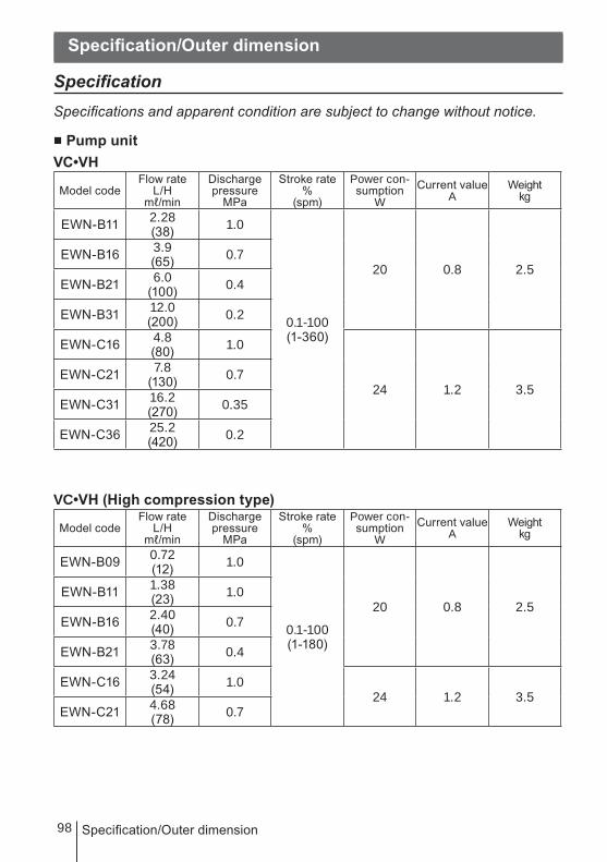
98 Specification/Outer dimension
Specification/Outer dimension
SpecificationSpecifications and apparent condition are subject to change without notice.
■ Pump unitVC•VH
Model codeFlow rate
L/Hmℓ/min
Discharge pressure
MPa
Stroke rate%
(spm)
Power con-sumption
WCurrent value
AWeight
kg
EWN-B11 2.28(38) 1.0
0.1-100(1-360)
20 0.8 2.5EWN-B16 3.9
(65) 0.7
EWN-B21 6.0(100) 0.4
EWN-B31 12.0(200) 0.2
EWN-C16 4.8(80) 1.0
24 1.2 3.5EWN-C21 7.8
(130) 0.7
EWN-C31 16.2(270) 0.35
EWN-C36 25.2(420) 0.2
VC•VH (High compression type)
Model codeFlow rate
L/Hmℓ/min
Discharge pressure
MPa
Stroke rate%
(spm)
Power con-sumption
WCurrent value
AWeight
kg
EWN-B09 0.72(12) 1.0
0.1-100(1-180)
20 0.8 2.5EWN-B11 1.38
(23) 1.0
EWN-B16 2.40(40) 0.7
EWN-B21 3.78(63) 0.4
EWN-C16 3.24(54) 1.0
24 1.2 3.5EWN-C21 4.68
(78) 0.7
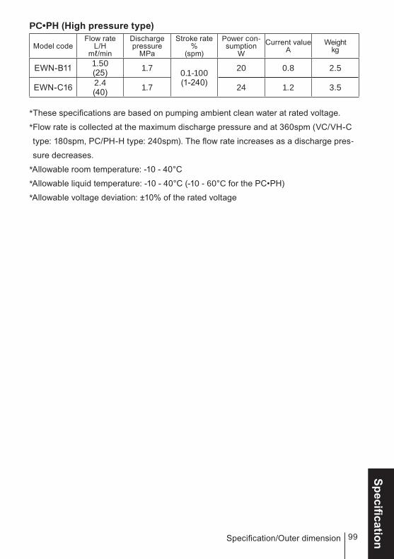
99
SpecificationSpecification/Outer dimension
PC•PH (High pressure type)
Model codeFlow rate
L/Hmℓ/min
Discharge pressure
MPa
Stroke rate%
(spm)
Power con-sumption
WCurrent value
AWeight
kg
EWN-B11 1.50(25) 1.7 0.1-100
(1-240)
20 0.8 2.5
EWN-C16 2.4(40) 1.7 24 1.2 3.5
* These specifications are based on pumping ambient clean water at rated voltage.
* Flow rate is collected at the maximum discharge pressure and at 360spm (VC/VH-C
type: 180spm, PC/PH-H type: 240spm). The flow rate increases as a discharge pres-
sure decreases.
* Allowable room temperature: -10 - 40°C
* Allowable liquid temperature: -10 - 40°C (-10 - 60°C for the PC•PH)
* Allowable voltage deviation: ±10% of the rated voltage

100 Specification/Outer dimension
■ Control unit
Types WPO WEC WCT
FunctionsOperation mode
Operation at a manual spm
AUTO proportional or PID control AUTO blowdown control
Mode change Key operation
Measurement
Measuring object pH/ORP Conductivity
Measurement range
0.00 - 14.00pH-2000 - 2000mV 0 - 400mS/m
Calibration
AUTO (1 or 2Pt calibration)MAN(1 or 2Pt calibration)
Cell constant settingReading correction
Temp. compensation
AUTO Pt1000 (0 - 50°C)Man (fixed)
Keypad SET, CAL, ESC, START/STOP, UP, DOWN
Controlfunction
STOP Operation stop at contact input*1
Interlock Operation stop at contact input*1
Priming Max spm operation by pressing the UP and DOWN keys
Keypad lock Keypad lock and release
Monitors
LCD 7×4, 14×4 backlit LCD indicates information such as measured values, operating conditions and units
LED
ON Green/Orange ×1 Lights greenly as powered on. Lights greenly while ready for operation Flash greenly during operationSTOP Red/Orange ×1 Lights redly at STOP signal input Lights orange at PreSTOP signal inputOUT Red ×2 Lights at each output
Input
STOP/PreSTOP No voltage contact or Open collector*2
AUX No voltage contact or Open collector*2
Interlock No voltage contact or Open collector*2
Output
OUT1
No voltage contact (mechanical relay) 250VAC, 3A(resistance load) Upper/Lower/Batch*3 alarm are settable. (Factory default is: Upper alarm)
Open collectorFor blowdown control onlyUsed with a relay type multibox)*5
OUT2No voltage contact (photoMOS) 24VAC/DC 0.1A Upper/Lower/Batch*3/Synchronous alarm are settable.(Factory default: Batch alarm turns on at STOP signal input)
Storage function Nonvolatile memory
Power voltage*4 100-240VAC 50/60Hz

101
SpecificationSpecification/Outer dimension
*1 Operation at contact input is also programmable.
*2 The maximum applied voltage is 12V at 2.3mA. The minimum application load
should be 2.3mA or below when using a relay.
*3 Interlock, STOP, PreSTOP, AUX and Sensor failure can be set to the batch alarm at
once.
*4 Observe the allowable voltage range of 90-264VAC. Otherwise failure may result.
*5 The contact capacity of the multibox (relay type) is 250VAC 3A(resistive load)
■ Power cableWPO/WEC type
Conductionsection area 0.75 [mm2] Triplex cable(L/N/PE) Standard H03VV-F
Length 1950 [mm] Terminaltreatment European plug
WCT typeConductionsection area
0.75 [mm2] Triplex cable(L/N/PE) Standard H03VV-F
Length 1950 [mm] Terminaltreatment
Power: Spade terminal (V1.25-YS4A or equivalent)
Earth: Bare wire
■ Pump colourBlue Munsell colour system 7.5PB 3/8Red Munsell colour system 5R 3/10

102 Specification/Outer dimension
Outer dimensions■ EWN-[B09•B11•B16•B21•C16•C21] [VC•VH] (-C)
■ EWN-[B31•C31] [VC•VH]
AIRLOCK
IN
OUT
(232
)(292)
100 (1
64) (199
)
(23)125
(47)
A 10
40
116 100 6 80
106
152015 20
(30)
(24)
WPO(BNC) (114)WEC/WCT (98)
WPOA
MODEL mm
(232
)
(295)10
0(1
76) (211
)
(25)125
(48)
(98) 10
(30)(6
)
LOCKAIR
IN
OUT
40
116 100 6 80
106
152015 20
MODELWPO(BNC) (114)WEC/WCT (98)
mm
WPOA
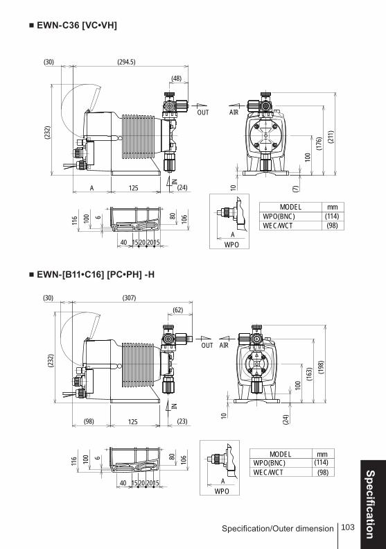
103
SpecificationSpecification/Outer dimension
■ EWN-C36 [VC•VH]
■ EWN-[B11•C16] [PC•PH] -H
40
116 100 6 80
106
152015 20
(232
)
(294.5)
100
(176
) (211
)
(24)125
(48)
A 10
(30)
(7)
LOCKAIR
IN
OUT
WPO(BNC) (114)WEC/WCT (98)
WPOA
MODEL mm
LOCK
(232
)
(307)10
0 (163
) (198
)
(23)125
(62)
(98) 10
(30)
(24)
AIR
IN
OUT
40
116 100 6 80
106
152015 20
WPO(BNC) (114)WEC/WCT (98)
WPOA
MODEL mm

2008 IWAKI CO., LTD.
IwakiElectromagnetic Metering PumpEWN-W (For water quality control)
Instruction manual Thank you for choosing our product.
Please read through this instruction manual before use.
This instruction manual describes important precautions and instructions for the product. Always keep it on hand for quick reference.
Safety instructionsO
utlineInstallation
Operation
Maintenance
SpecificationT696 '09/08
( )Country codes
IWAKI CO.,LTD. 6-6 Kanda-Sudacho 2-chome Chiyoda-ku Tokyo 101-8558 JapanTEL:(81)3 3254 2935 FAX:3 3252 8892(http://www.iwakipumps.jp)
Australia IWAKI Pumps Australia Pty. Ltd. TEL : (61)2 9899 2411 FAX : 2 9899 2421 Italy IWAKI Italia S.R.L. TEL : (39)02 990 3931 FAX : 02 990 42888Austria IWAKI (Austria) GmbH TEL : (43)2236 33469 FAX : 2236 33469 Korea IWAKI Korea Co.,Ltd. TEL : (82)2 2630 4800 FAX : 2 2630 4801Belgium IWAKI Belgium n.v. TEL : (32)1367 0200 FAX : 1367 2030 Malaysia IWAKIm Sdn. Bhd. TEL : (60)3 7803 8807 FAX : 3 7803 4800China IWAKI Pumps (Shanghai) Co., Ltd. TEL : (86)21 6272 7502 FAX : 21 6272 6929 Norway IWAKI Norge AS TEL : (47)66 81 16 60 FAX : 66 81 16 61China IWAKI Pumps (Guandong) Co., Ltd. TEL : (86)750 3866228 FAX : 750 3866278 Singapore IWAKI Singapore Pte. Ltd. TEL : (65)6316 2028 FAX : 6316 3221China GFTZ IWAKI Engineering & Trading (Guangzhou) TEL : (86)20 8435 0603 FAX : 20 8435 9181 Spain IWAKI Iberica Pumps, S.A. TEL : (34)943 630030 FAX : 943 628799China GFTZ IWAKI Engineering & Trading (Beijing) TEL : (86)10 6442 7713 FAX : 10 6442 7712 Sweden IWAKI Sverige AB TEL : (46)8 511 72900 FAX : 8 511 72922Denmark IWAKI Nordic A/S TEL : (45)48 24 2345 FAX : 48 24 2346 Switzerland IWAKI (Schweiz) AG TEL : (41)26 674 9300 FAX : 26 674 9302Finland IWAKI Suomi Oy TEL : (358)9 2745810 FAX : 9 2742715 Taiwan IWAKI Pumps Taiwan Co., Ltd. TEL : (886)2 8227 6900 FAX : 2 8227 6818France IWAKI France S.A. TEL : (33)1 69 63 33 70 FAX : 1 64 49 92 73 Taiwan IWAKI Pumps Taiwan (Hsin-chu) Co., Ltd. TEL : (886)3 573 5797 FAX : (886)3 573 5798Germany IWAKI EUROPE GmbH TEL : (49)2154 9254 0 FAX : 2154 9254 48 Thailand IWAKI (Thailand) Co.,Ltd. TEL : (66)2 322 2471 FAX : 2 322 2477Holland IWAKI Holland B.V. TEL : (31)297 241121 FAX : 297 273902 U.K. IWAKI PUMPS (UK) LTD. TEL : (44)1743 231363 FAX : 1743 366507Hong Kong IWAKI Pumps Co., Ltd. TEL : (852)2 607 1168 FAX : 2 607 1000 U.S.A. IWAKI America Incorporated TEL : (1)508 429 1440 FAX : 508 429 1386Indonesia IWAKI Singapore (Indonesia Branch) TEL : (62)21 690 6606 FAX : 21 690 6612 Vietnam IWAKI Pumps Vietnam Co.,Ltd. TEL : (84)613 933456 FAX : 613 933399