Embed Size (px)
Citation preview
STAY AWAY - STAY SAFE
SAFETY GUARDING SOLUTIONS

2 [email protected] | 1-866-300-6668 | www.conveyorguarding.com
EXPERTS IN GUARDING, INNOVATORS IN PRODUCTIVITY
BELT CONVEYOR GUARDING is the industry leader in designing and manufacturing safety guarding solutions that have proven to assist in eliminating workplace injuries. Our complete line of customized products and services provide the highest levels of safety, quality, and innovation available on the market. Benefits include:
Eliminating workplace injuries Increasing productivity Decreasing fines, citations, and costly shutdowns Extending the life of your equipment Ensuring compliance
Along with an extensive range of safety products, Belt Conveyor Guarding offers Safety Guarding Assessments. Guarding Assessments have been designed to identify areas of risk, identify relevant infractions, and propose detailed solutions that are compliant with industry standards. They are beneficial and convenient for companies that don't have the time and/or resources to undertake an internal safety audit. We will send in a safety technician to assess your facility and present you with a detailed report highlighting areas of concern. As each company has different needs and objectives, we offer different levels of assessments to make certain you get what you require.
Belt Conveyor Guarding is proud to be the only full service safety guarding company in North America and continues to develop leading edge products and services.
OUR PRODUCTS ARE COMPLIANT WITH THE FOLLOWING SAFE GUARDING STANDARDS:
MSHA OSHA CSA56/57.14110 Flying or falling material 1910.219 Mechanical power transmission
apparatus 6.3.3.2.2 Requirements for fixed guards
56/57.14112 Guard construction 1926.555 Conveyor passes over employee 7.4 Rotating shafts, spindles, couplings
56/57.14107 Moving machine parts 1917.48 Danger zone adjacent to conveyor 9.1.1 Guards & protective devices
75.1722 Mechanical equipment guards
Please note: Not all products comply with every standard
Toll Free: 1-866-300-6668 | Fax: 1-705-725-8835safety@conveyorguarding.comwww.conveyorguarding.com
[email protected] | 1-866-300-6668 | www.conveyorguarding.com
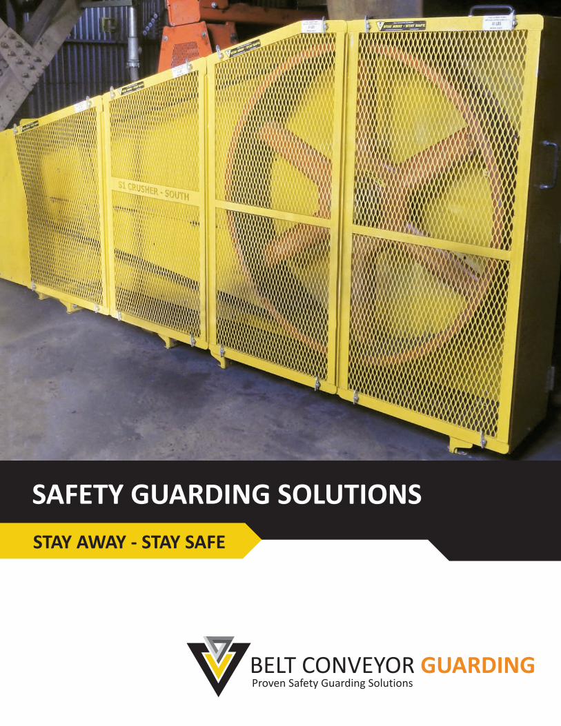
TABLE OF CONTENTS
EXPECT EXCEPTIONAL SERVICE 4
ROI & MAINTENANCE 5
SAFETY GAUGE 6
MESH SIZE & TYPES 7
SAFETY GUARDING ASSESSMENT 8
RISK MATRIX 9
WEDGE CLAMPS 10
LOCKING WEDGE CLAMPS 11
FLAT GUARDS 12
FLAT GUARD MOUNTING OPTIONS 13/14
MODULAR BARRIER GUARDS 15
GRINDING MILL GUARDS 16
ROLLING SAFETY GATES 17
COUPLING GUARDS 18
PUMP GUARDS 19
V-BELT GUARDS 20
BEARING GUARDS 21
FLANGE BEARING GUARDS 22
RETURN IDLER BASKETS 23
RETURN IDLER BASKETS - CERAMIC 24
RETURN IDLER GUARDS 25
RETURN IDLER BELLY GUARDS 26
RETURN IDLER SIDE GUARDS 27
GUARD HANGERS & CABLE TIE CADDIES 28
HANDLES 29
HANDRAILS 30
SERVICE/INSPECTION DOORS 31
SIGNS & DECALS 32
PUMP & V-BELT GUARD DATA SHEET SELECTION CHART 33
PUMP GUARD DATA SHEETS 34/35
V-BELT GUARD DATA SHEETS 36/37/38
COUPLING GUARD DATA SHEET 39
BEARING GUARD DATA SHEET 40
FLANGE BEARING GUARD DATA SHEET 41
PARTS IDENTIFICATION / ASSEMBLY & INSTALLATION 42
COMPLIANT GUARDING SYSTEMS 43
GUARDING FASTENERS
MULTI-PURPOSE GUARDING
DRIVE GUARDS
ROTATING SHAFT GUARDS
RETURN IDLER BASKETS
RISK ASSESSMENTS
GENERAL GUARDING DATA
RETURN IDLER GUARDS
DATA SHEETS
ACCESSORIES
GENERAL GUARDING DATA
4 [email protected] | 1-866-300-6668 | www.conveyorguarding.com
EXPECT EXCEPTIONAL SERVICE
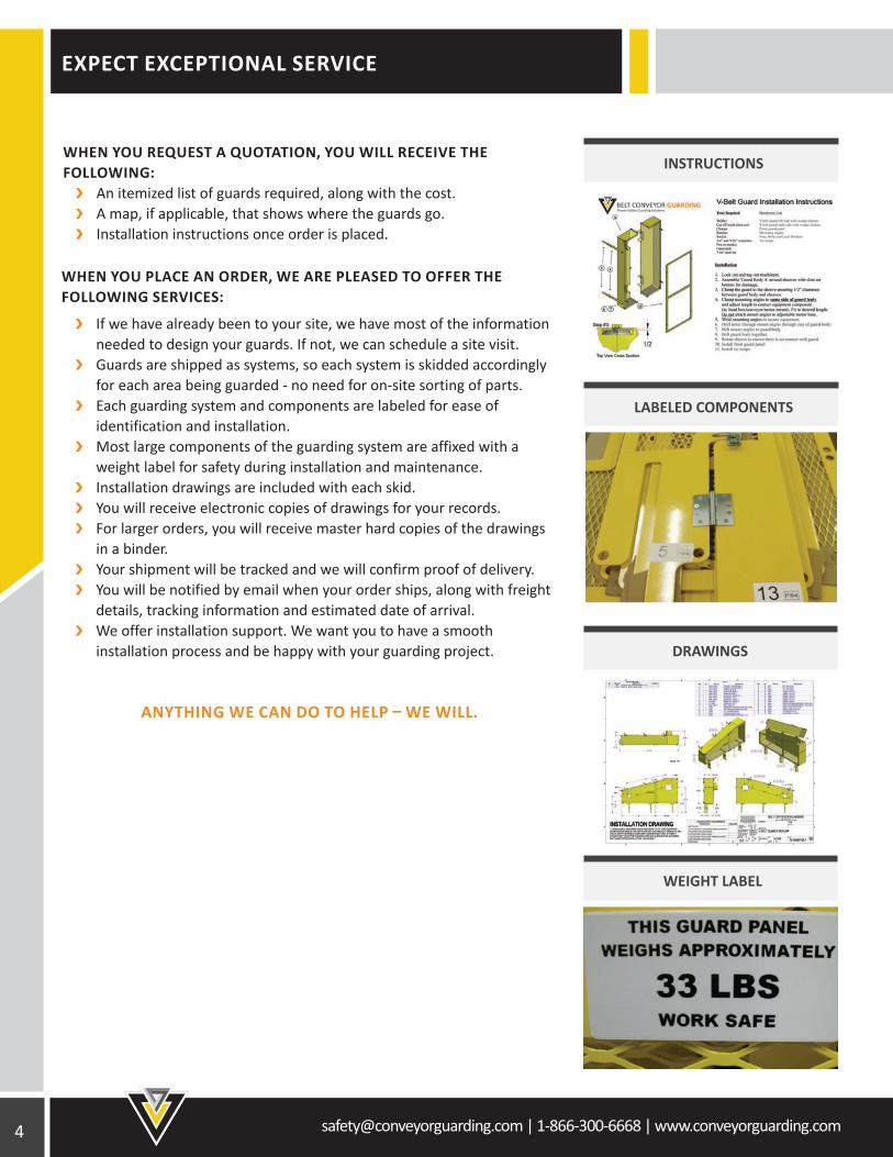
If we have already been to your site, we have most of the information needed to design your guards. If not, we can schedule a site visit. Guards are shipped as systems, so each system is skidded accordingly for each area being guarded - no need for on-site sorting of parts. Each guarding system and components are labeled for ease of identification and installation. Most large components of the guarding system are affixed with a weight label for safety during installation and maintenance. Installation drawings are included with each skid. You will receive electronic copies of drawings for your records. For larger orders, you will receive master hard copies of the drawings in a binder. Your shipment will be tracked and we will confirm proof of delivery. You will be notified by email when your order ships, along with freight details, tracking information and estimated date of arrival. We offer installation support. We want you to have a smooth installation process and be happy with your guarding project.
ANYTHING WE CAN DO TO HELP – WE WILL.
WEIGHT LABEL
DRAWINGS
LABELED COMPONENTS
INSTRUCTIONSWHEN YOU REQUEST A QUOTATION, YOU WILL RECEIVE THE FOLLOWING: An itemized list of guards required, along with the cost. A map, if applicable, that shows where the guards go. Installation instructions once order is placed.
WHEN YOU PLACE AN ORDER, WE ARE PLEASED TO OFFER THE FOLLOWING SERVICES:
[email protected] | 1-866-300-6668 | www.conveyorguarding.com
ROI AND MAINTENANCE
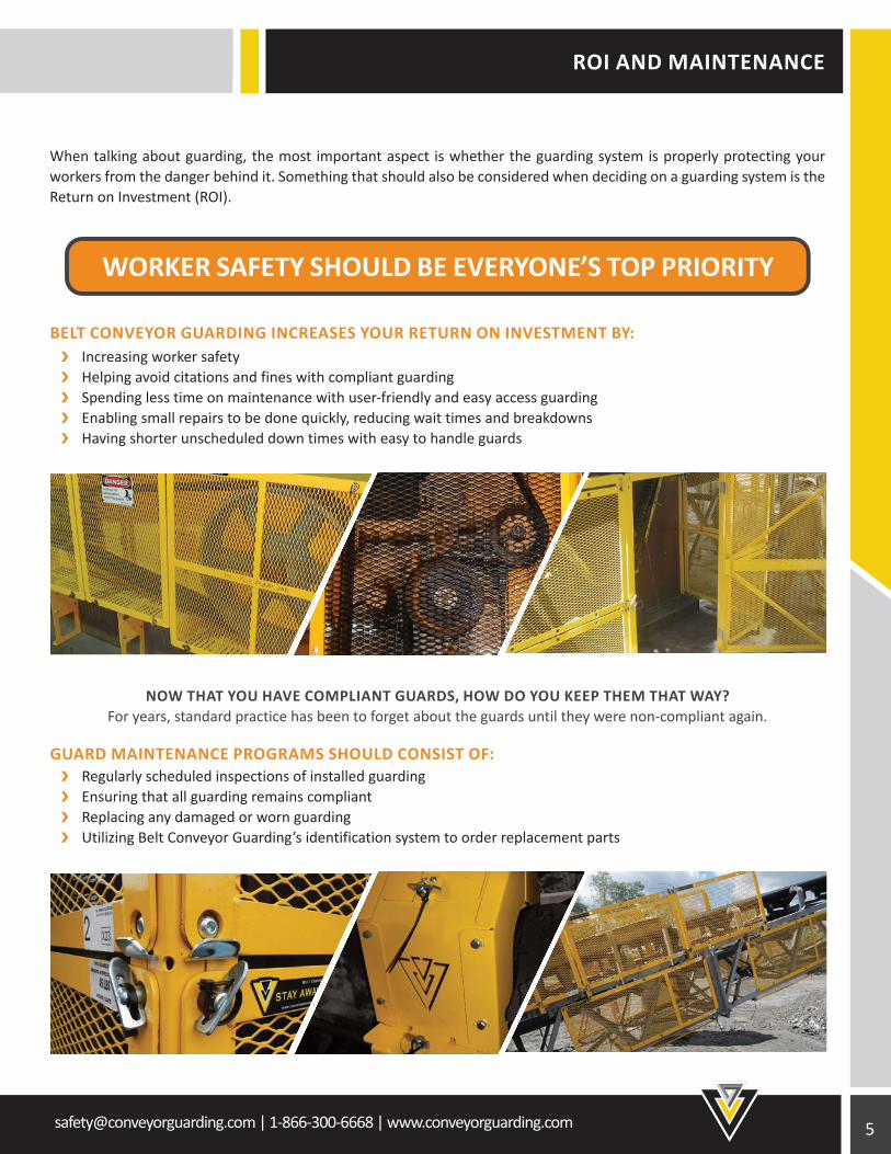
When talking about guarding, the most important aspect is whether the guarding system is properly protecting your workers from the danger behind it. Something that should also be considered when deciding on a guarding system is the Return on Investment (ROI).
BELT CONVEYOR GUARDING INCREASES YOUR RETURN ON INVESTMENT BY: Increasing worker safety Helping avoid citations and fines with compliant guarding Spending less time on maintenance with user-friendly and easy access guarding Enabling small repairs to be done quickly, reducing wait times and breakdowns Having shorter unscheduled down times with easy to handle guards
NOW THAT YOU HAVE COMPLIANT GUARDS, HOW DO YOU KEEP THEM THAT WAY? For years, standard practice has been to forget about the guards until they were non-compliant again.
GUARD MAINTENANCE PROGRAMS SHOULD CONSIST OF: Regularly scheduled inspections of installed guarding Ensuring that all guarding remains compliant Replacing any damaged or worn guarding Utilizing Belt Conveyor Guarding’s identification system to order replacement parts
Toll Free: 1-866-300-6668Fax: 1-705-725-8835
www.conveyorguarding.com
Toll Free: 1-866-300-6668 www.conveyorguarding.com
ARE YOUR SAFE GUARDS COMPLIANT?
WORKER SAFETY SHOULD BE EVERYONE’S TOP PRIORITY
STAY AWAY - STAY SAFE
How would you like to fix the guard to base or floor?
Conrete Anchor
Welded On
Standoff
How would you like to fix the guard to base or floor?
D
Welded On
Standoff
Please select appropriate mesh size:
SMALL MESH - When guard is 1/2” or greater away from pinch point/rotating partREGULAR MESH - When guard is 3 1/2” or greater away from pinch point/rotating partLARGE MESH - When guard is 6 1/2” or greater away from pinch point/rotating part
Toll Free: 1-866-230-8887www.reguarding.com
A
WORKER SAFETY SHOULD BE EVERYONE’S TOP PRIORITY
6 [email protected] | 1-866-300-6668 | www.conveyorguarding.com
SAFETY GAUGE
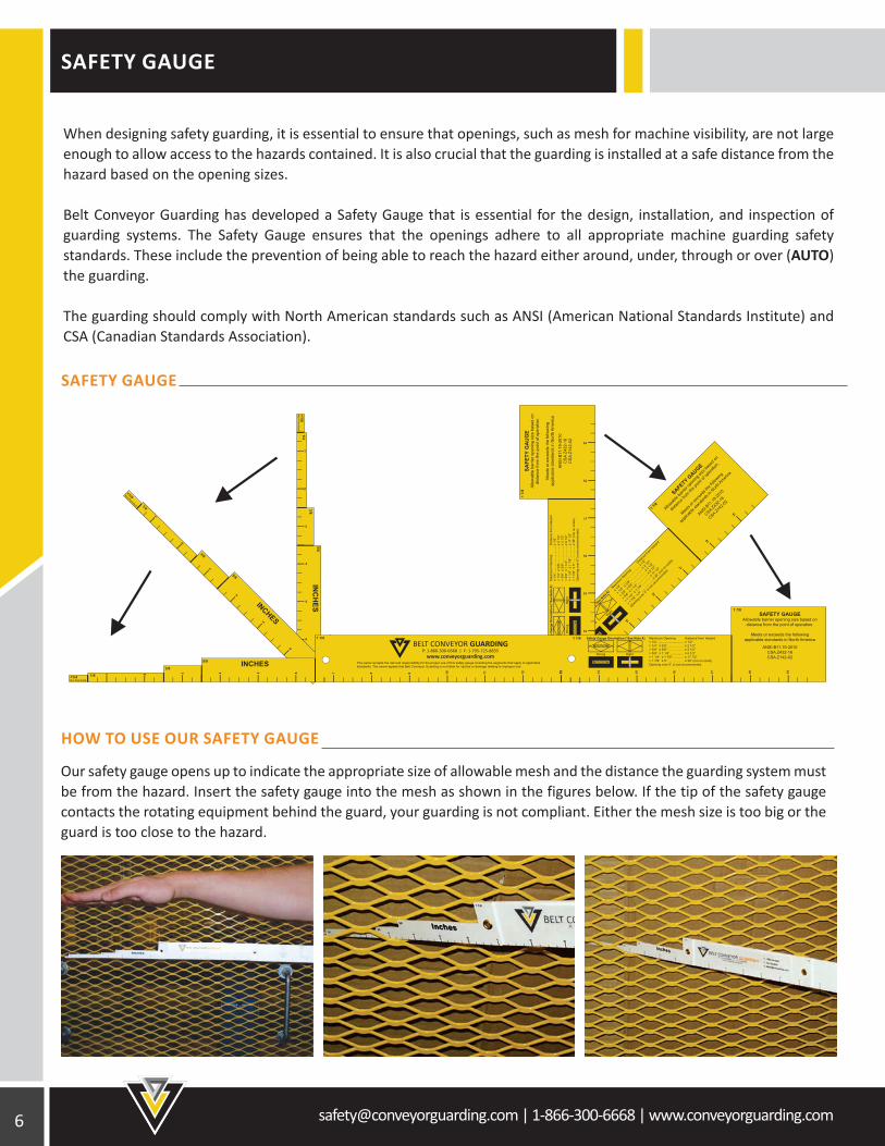
When designing safety guarding, it is essential to ensure that openings, such as mesh for machine visibility, are not large enough to allow access to the hazards contained. It is also crucial that the guarding is installed at a safe distance from the hazard based on the opening sizes.
Belt Conveyor Guarding has developed a Safety Gauge that is essential for the design, installation, and inspection of guarding systems. The Safety Gauge ensures that the openings adhere to all appropriate machine guarding safety standards. These include the prevention of being able to reach the hazard either around, under, through or over (AUTO) the guarding.
The guarding should comply with North American standards such as ANSI (American National Standards Institute) and CSA (Canadian Standards Association).
SAFETY GAUGE
HOW TO USE OUR SAFETY GAUGE
Our safety gauge opens up to indicate the appropriate size of allowable mesh and the distance the guarding system must be from the hazard. Insert the safety gauge into the mesh as shown in the figures below. If the tip of the safety gauge contacts the rotating equipment behind the guard, your guarding is not compliant. Either the mesh size is too big or the guard is too close to the hazard.
[email protected] | 1-866-300-6668 | www.conveyorguarding.com
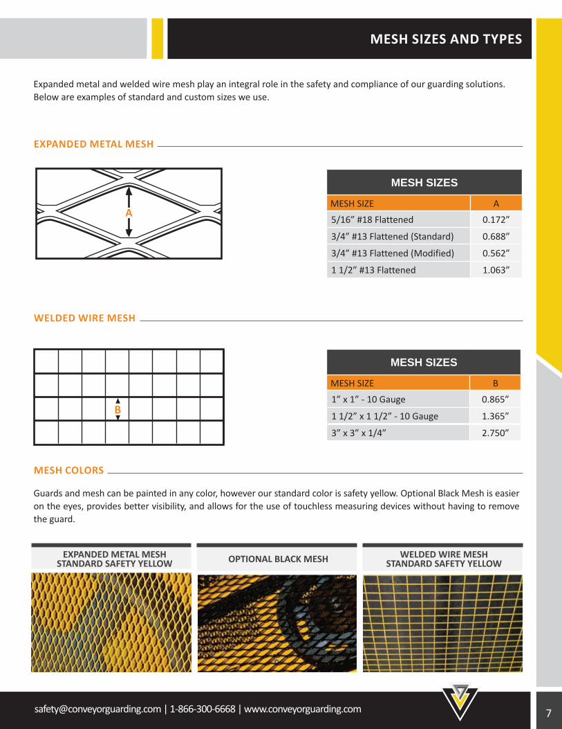
Expanded metal and welded wire mesh play an integral role in the safety and compliance of our guarding solutions. Below are examples of standard and custom sizes we use.
MESH SIZES
MESH SIZE A
5/16” #18 Flattened 0.172”
3/4” #13 Flattened (Standard) 0.688”
3/4” #13 Flattened (Modified) 0.562”
1 1/2” #13 Flattened 1.063”
MESH SIZES
MESH SIZE B
1” x 1” - 10 Gauge 0.865”
1 1/2” x 1 1/2” - 10 Gauge 1.365”
3” x 3” x 1/4” 2.750”
Guards and mesh can be painted in any color, however our standard color is safety yellow. Optional Black Mesh is easier on the eyes, provides better visibility, and allows for the use of touchless measuring devices without having to remove the guard.
EXPANDED METAL MESH
WELDED WIRE MESH
MESH COLORS
MESH SIZES AND TYPES
OPTIONAL BLACK MESH WELDED WIRE MESHSTANDARD SAFETY YELLOW
B
A
EXPANDED METAL MESHSTANDARD SAFETY YELLOW

8 [email protected] | 1-866-300-6668 | www.conveyorguarding.com
SAFETY GUARDING ASSESSMENT
As a starting point in developing an effective safety guarding policy, a safety guarding assessment is a great tool that will discover potential areas of risk, ensure compliancy, and educate stakeholders on proper safety guarding practices and procedures.
GUARDING TECHNICIANS WILL: Come to site Meet with stakeholders to review the assessment plan Assess the equipment for guarding determined by the plan Take pictures of equipment that requires guarding as identified in the plan Measure areas to ensure a tight and secure fit Recommend guarding upgrades based on either MSHA, OSHA or CSA Standards
OUR SERVICES INCLUDE: Risk Identification Risk Management Cost Projections & Breakdown Customized Guarding Designs Fabrication of Custom Guarding On-site Equipment Measurements and Photography On-site training for installers/ stakeholders
GUARDING ASSESSMENT REPORT INCLUDES: Itemized report showing pictures of non-compliant guarding Description of guarding deficiencies Itemized quote showing cost to supply new guarding Risk analysis for each guard quoted
OTHER BENEFITS INCLUDE: Discovering solutions to reduce unnecessary workplace injuries Developing an understanding of the requirements and scope of a tailored guarding project Eliminating ineffective guarding systems and ensuring industry compliancy Increasing productivity

[email protected] | 1-866-300-6668 | www.conveyorguarding.com
RISK MATRIX
ONCE A SAFETY GUARDING ASSESSMENT HAS BEEN COMPLETED, THIS MATRIX WILL HELP YOU PRIORITIZE YOUR GUARDING PROJECT.
Overall risk score range: 4-18. Risk is acceptable and no further action is necessary.
Overall risk score range: 20-26. Additional controls should be considered to bring machine risks into an acceptable range.
Overall risk score range: 40-160. Risk is unacceptable. Guarding needs to be designed and implemented to bring risks into acceptable range.
0.1
16
12
8
6
4
0.9
160 53 26 18
120 40 20 13
80 26 13 9
60 20 10 6
40 13
GUARDING FACTOR
P = PROBABILITY OF CONTACTS = INJURY SEVERITYG = GUARDING FACTOR
OVERALL RISK =
PRO
BABI
LITY
OF
CONT
ACT
(P) X
INJU
RY S
EVER
ITY
(S)
P X SG
6 4
0.3 0.6
10 [email protected] | 1-866-300-6668 | www.conveyorguarding.com
WEDGE CLAMP
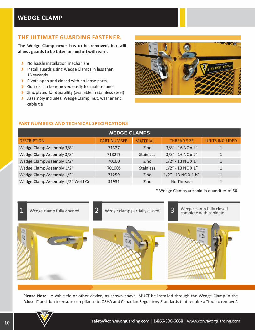
THE ULTIMATE GUARDING FASTENER. The Wedge Clamp never has to be removed, but still allows guards to be taken on and off with ease.
No hassle installation mechanism Install guards using Wedge Clamps in less than 15 seconds Pivots open and closed with no loose parts Guards can be removed easily for maintenance Zinc plated for durability (available in stainless steel) Assembly includes: Wedge Clamp, nut, washer and cable tie
WEDGE CLAMPSDESCRIPTION PART NUMBER MATERIALM THREAD SIZE UNITS INCLUDEDWedge Clamp Assembly 3/8” 71327 Zinc 3/8” - 16 NC x 1” 1Wedge Clamp Assembly 3/8” 71327S Stainless 3/8” - 16 NC x 1” 1Wedge Clamp Assembly 1/2” 70100 Zinc 1/2” - 13 NC X 1” 1Wedge Clamp Assembly 1/2” 70100S Stainless 1/2” - 13 NC X 1” 1Wedge Clamp Assembly 1/2” 71259 Zinc 1/2” - 13 NC X 1 ½” 1Wedge Clamp Assembly 1/2” Weld On 31931 Zinc No Threads 1
* Wedge Clamps are sold in quantities of 50
PART NUMBERS AND TECHNICAL SPECIFICATIONS
Please Note: A cable tie or other device, as shown above, MUST be installed through the Wedge Clamp in the “closed” position to ensure compliance to OSHA and Canadian Regulatory Standards that require a “tool to remove”.
Wedge clamp fully closed complete with cable tie3Wedge clamp partially closed2Wedge clamp fully opened1
[email protected] | 1-866-300-6668 | www.conveyorguarding.com
LOCKING WEDGE CLAMP
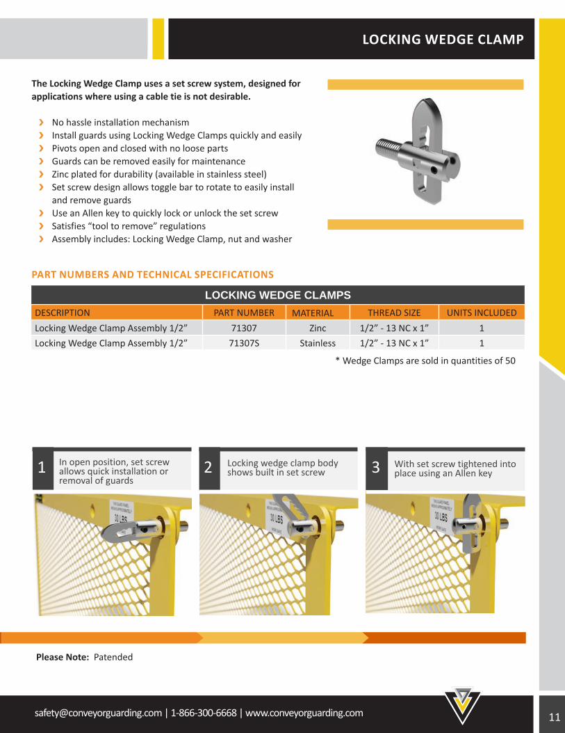
The Locking Wedge Clamp uses a set screw system, designed for applications where using a cable tie is not desirable.
No hassle installation mechanism Install guards using Locking Wedge Clamps quickly and easily Pivots open and closed with no loose parts Guards can be removed easily for maintenance Zinc plated for durability (available in stainless steel) Set screw design allows toggle bar to rotate to easily install and remove guards Use an Allen key to quickly lock or unlock the set screw Satisfies “tool to remove” regulations Assembly includes: Locking Wedge Clamp, nut and washer
* Wedge Clamps are sold in quantities of 50
PART NUMBERS AND TECHNICAL SPECIFICATIONS
LOCKING WEDGE CLAMPSDESCRIPTION PART NUMBER MATERIALM THREAD SIZE UNITS INCLUDEDLocking Wedge Clamp Assembly 1/2” 71307 Zinc 1/2” - 13 NC x 1” 1Locking Wedge Clamp Assembly 1/2” 71307S Stainless 1/2” - 13 NC x 1” 1
Please Note: Patended
With set screw tightened into place using an Allen key3Locking wedge clamp body
shows built in set screw2In open position, set screw allows quick installation or removal of guards
1
12 [email protected] | 1-866-300-6668 | www.conveyorguarding.com
FLAT GUARDS
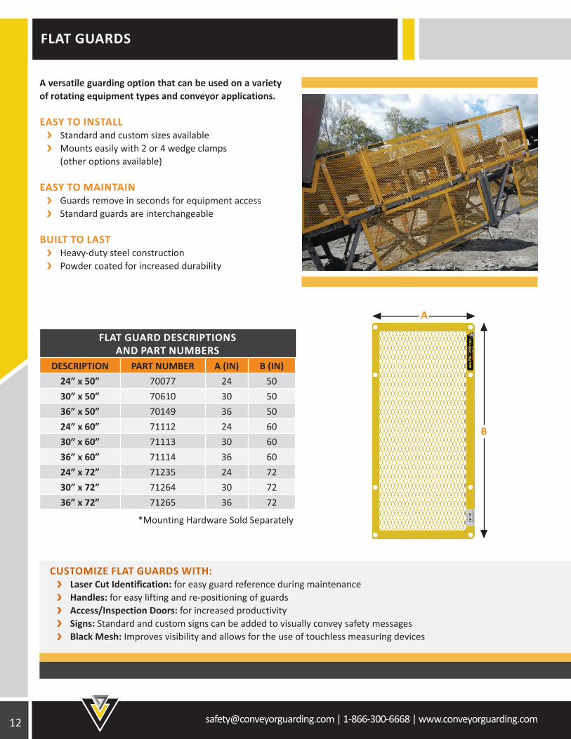
FLAT GUARD DESCRIPTIONS AND PART NUMBERS
DESCRIPTION PART NUMBER A (IN) B (IN)24” x 50” 70077 24 5030” x 50” 70610 30 5036” x 50” 70149 36 5024” x 60” 71112 24 6030” x 60” 71113 30 6036” x 60” 71114 36 6024” x 72” 71235 24 7230” x 72” 71264 30 7236” x 72” 71265 36 72
*Mounting Hardware Sold Separately
A versatile guarding option that can be used on a variety of rotating equipment types and conveyor applications.
EASY TO INSTALL Standard and custom sizes available Mounts easily with 2 or 4 wedge clamps (other options available)
EASY TO MAINTAIN Guards remove in seconds for equipment access Standard guards are interchangeable
BUILT TO LAST Heavy-duty steel construction Powder coated for increased durability
CUSTOMIZE FLAT GUARDS WITH: Laser Cut Identification: for easy guard reference during maintenance Handles: for easy lifting and re-positioning of guards Access/Inspection Doors: for increased productivity Signs: Standard and custom signs can be added to visually convey safety messages Black Mesh: Improves visibility and allows for the use of touchless measuring devices
B
A
[email protected] | 1-866-300-6668 | www.conveyorguarding.com
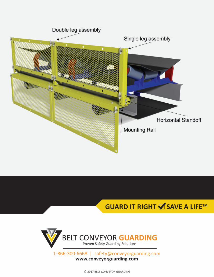
FLAT GUARD MOUNTING OPTIONS
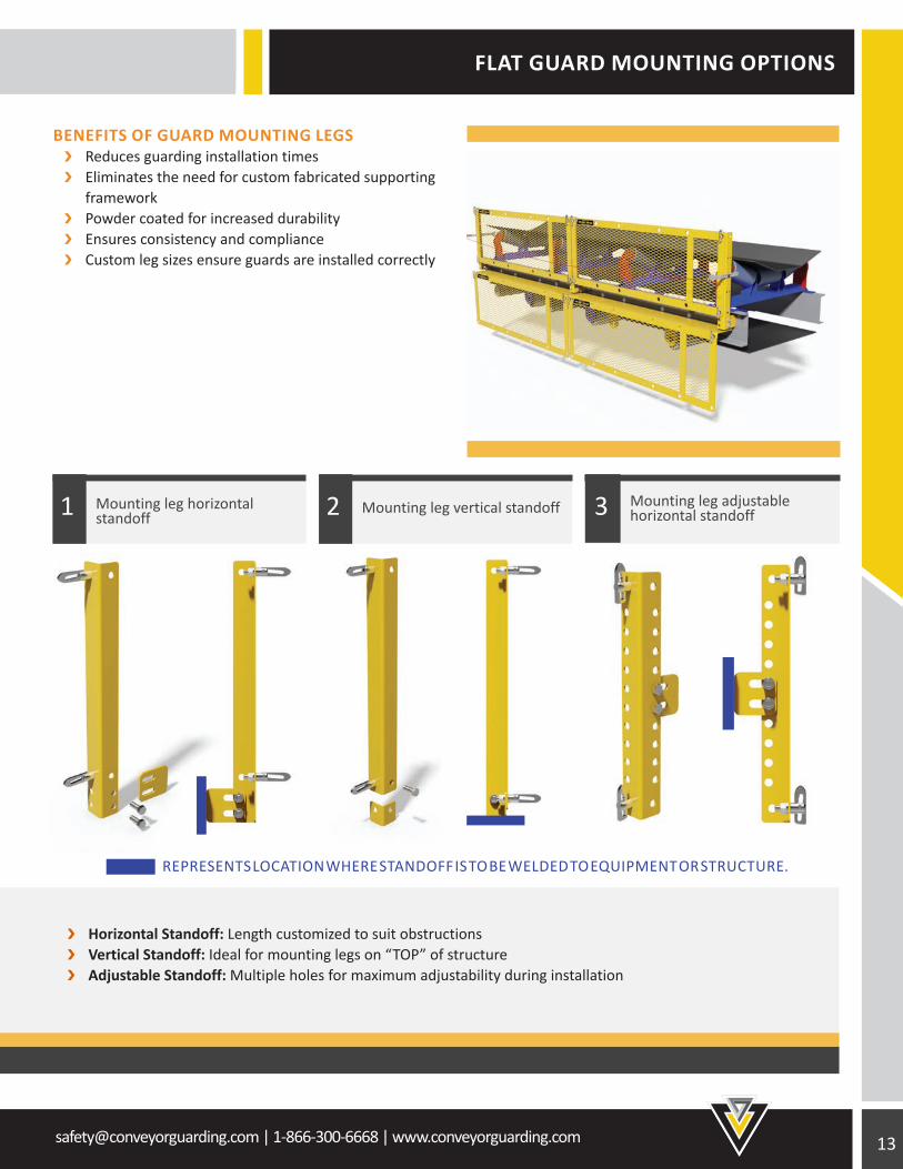
REPRESENTS LOCATION WHERE STANDOFF IS TO BE WELDED TO EQUIPMENT OR STRUCTURE.
BENEFITS OF GUARD MOUNTING LEGS Reduces guarding installation times Eliminates the need for custom fabricated supporting framework Powder coated for increased durability Ensures consistency and compliance Custom leg sizes ensure guards are installed correctly
Horizontal Standoff: Length customized to suit obstructions Vertical Standoff: Ideal for mounting legs on “TOP” of structure Adjustable Standoff: Multiple holes for maximum adjustability during installation
Mounting leg adjustable horizontal standoff3Mounting leg vertical standoff2Mounting leg horizontal
standoff1
14 [email protected] | 1-866-300-6668 | www.conveyorguarding.com
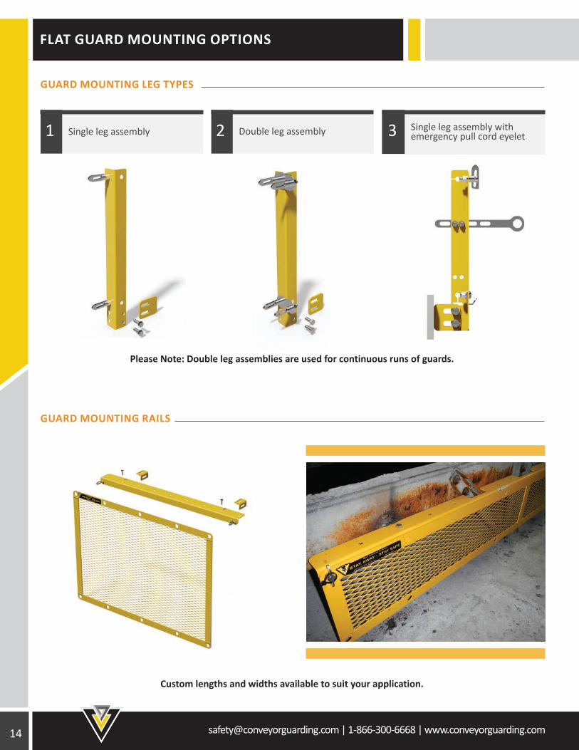
FLAT GUARD MOUNTING OPTIONS
Please Note: Double leg assemblies are used for continuous runs of guards.
Custom lengths and widths available to suit your application.
GUARD MOUNTING LEG TYPES
GUARD MOUNTING RAILS
Single leg assembly with emergency pull cord eyelet3Double leg assembly2Single leg assembly1
[email protected] | 1-866-300-6668 | www.conveyorguarding.com
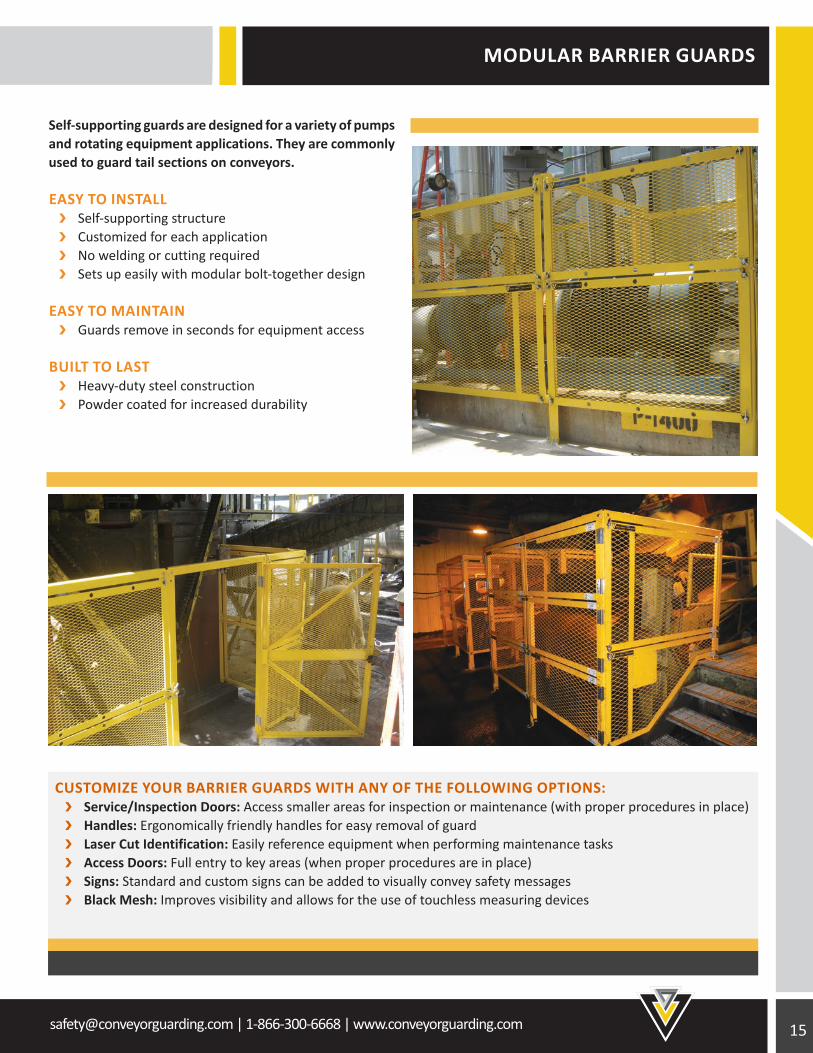
MODULAR BARRIER GUARDS
Self-supporting guards are designed for a variety of pumps and rotating equipment applications. They are commonly used to guard tail sections on conveyors.
EASY TO INSTALL Self-supporting structure Customized for each application No welding or cutting required Sets up easily with modular bolt-together design
EASY TO MAINTAIN Guards remove in seconds for equipment access
BUILT TO LAST Heavy-duty steel construction Powder coated for increased durability
CUSTOMIZE YOUR BARRIER GUARDS WITH ANY OF THE FOLLOWING OPTIONS: Service/Inspection Doors: Access smaller areas for inspection or maintenance (with proper procedures in place) Handles: Ergonomically friendly handles for easy removal of guard Laser Cut Identification: Easily reference equipment when performing maintenance tasks Access Doors: Full entry to key areas (when proper procedures are in place) Signs: Standard and custom signs can be added to visually convey safety messages Black Mesh: Improves visibility and allows for the use of touchless measuring devices
16 [email protected] | 1-866-300-6668 | www.conveyorguarding.com
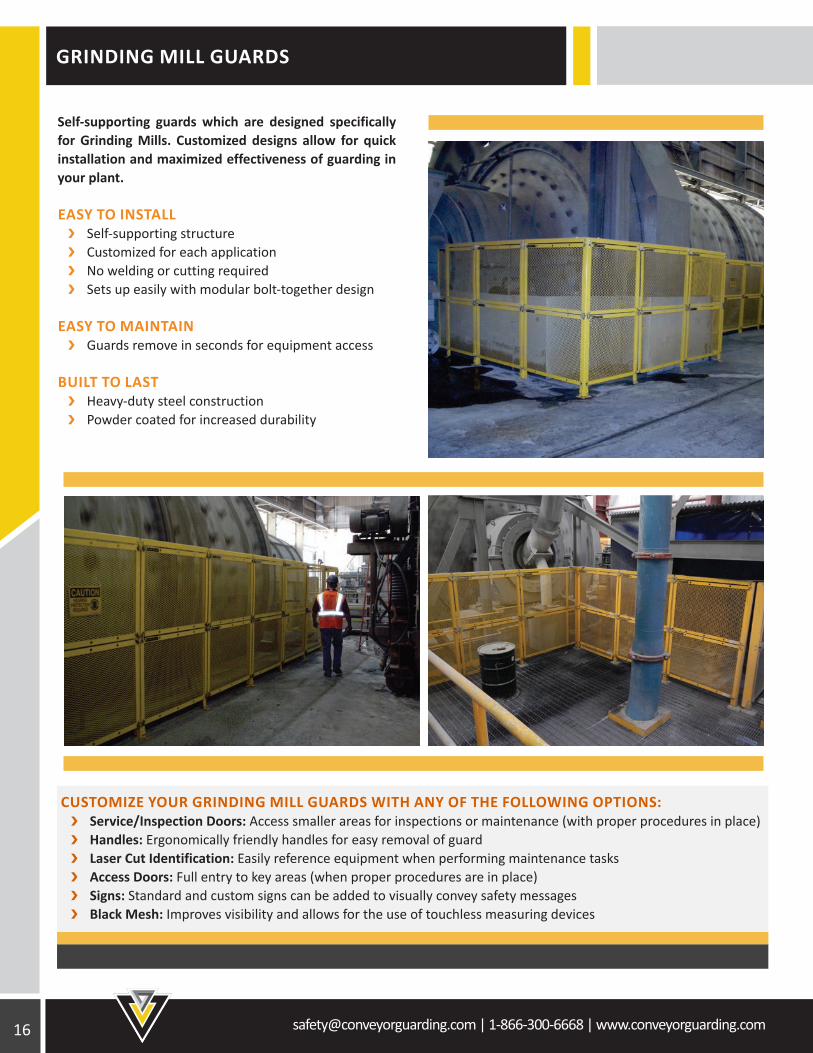
GRINDING MILL GUARDS
Self-supporting guards which are designed specifically for Grinding Mills. Customized designs allow for quick installation and maximized effectiveness of guarding in your plant.
EASY TO INSTALL Self-supporting structure Customized for each application No welding or cutting required Sets up easily with modular bolt-together design
EASY TO MAINTAIN Guards remove in seconds for equipment access
BUILT TO LAST Heavy-duty steel construction Powder coated for increased durability
CUSTOMIZE YOUR GRINDING MILL GUARDS WITH ANY OF THE FOLLOWING OPTIONS: Service/Inspection Doors: Access smaller areas for inspections or maintenance (with proper procedures in place) Handles: Ergonomically friendly handles for easy removal of guard Laser Cut Identification: Easily reference equipment when performing maintenance tasks Access Doors: Full entry to key areas (when proper procedures are in place) Signs: Standard and custom signs can be added to visually convey safety messages Black Mesh: Improves visibility and allows for the use of touchless measuring devices
[email protected] | 1-866-300-6668 | www.conveyorguarding.com
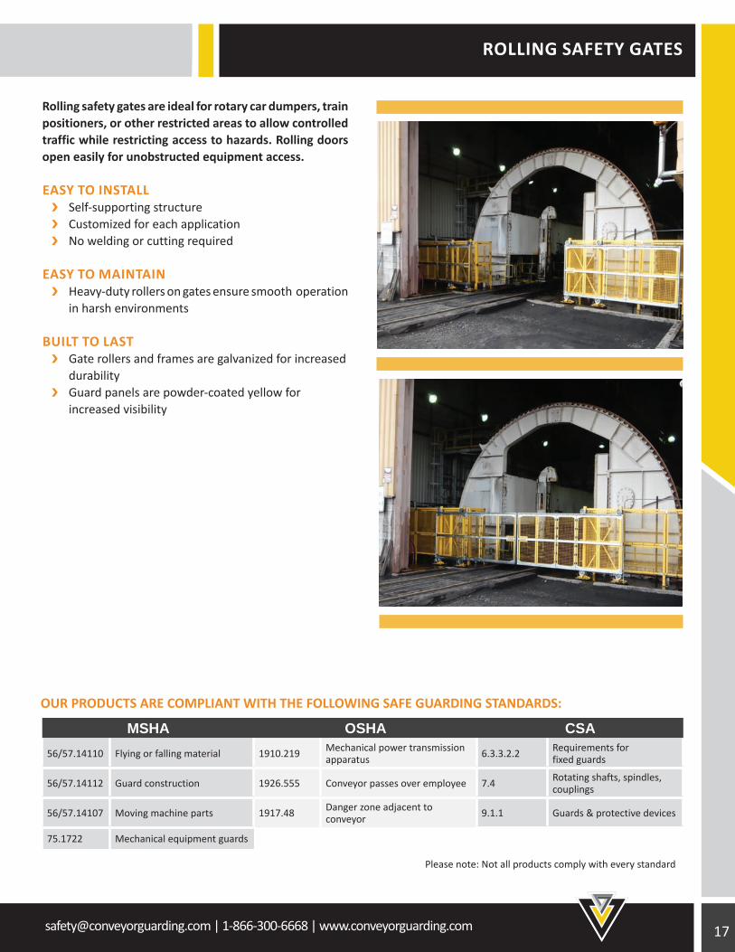
ROLLING SAFETY GATES
Rolling safety gates are ideal for rotary car dumpers, train positioners, or other restricted areas to allow controlled traffic while restricting access to hazards. Rolling doors open easily for unobstructed equipment access.
EASY TO INSTALL Self-supporting structure Customized for each application No welding or cutting required
EASY TO MAINTAIN Heavy-duty rollers on gates ensure smooth operation in harsh environments
BUILT TO LAST Gate rollers and frames are galvanized for increased durability Guard panels are powder-coated yellow for increased visibility
OUR PRODUCTS ARE COMPLIANT WITH THE FOLLOWING SAFE GUARDING STANDARDS:
MSHA OSHA CSA56/57.14110 Flying or falling material 1910.219 Mechanical power transmission
apparatus 6.3.3.2.2 Requirements for fixed guards
56/57.14112 Guard construction 1926.555 Conveyor passes over employee 7.4 Rotating shafts, spindles, couplings
56/57.14107 Moving machine parts 1917.48 Danger zone adjacent to conveyor 9.1.1 Guards & protective devices
75.1722 Mechanical equipment guards
Please note: Not all products comply with every standard
18 [email protected] | 1-866-300-6668 | www.conveyorguarding.com
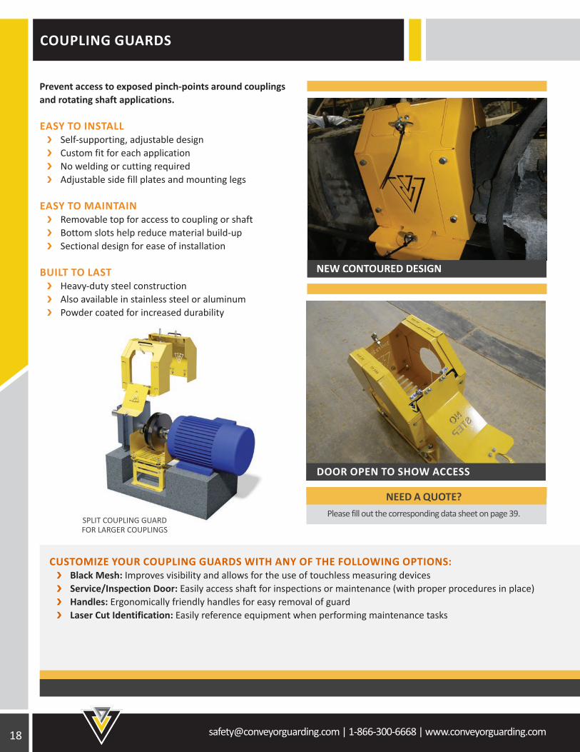
COUPLING GUARDS
Prevent access to exposed pinch-points around couplings and rotating shaft applications.
EASY TO INSTALL Self-supporting, adjustable design Custom fit for each application No welding or cutting required Adjustable side fill plates and mounting legs
EASY TO MAINTAIN Removable top for access to coupling or shaft Bottom slots help reduce material build-up Sectional design for ease of installation
BUILT TO LAST Heavy-duty steel construction Also available in stainless steel or aluminum Powder coated for increased durability
CUSTOMIZE YOUR COUPLING GUARDS WITH ANY OF THE FOLLOWING OPTIONS: Black Mesh: Improves visibility and allows for the use of touchless measuring devices Service/Inspection Door: Easily access shaft for inspections or maintenance (with proper procedures in place) Handles: Ergonomically friendly handles for easy removal of guard Laser Cut Identification: Easily reference equipment when performing maintenance tasks
NEW CONTOURED DESIGN
DOOR OPEN TO SHOW ACCESS
SPLIT COUPLING GUARD FOR LARGER COUPLINGS
NEED A QUOTE? Please fill out the corresponding data sheet on page 39.
[email protected] | 1-866-300-6668 | www.conveyorguarding.com
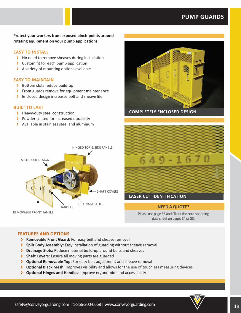
PUMP GUARDS
Protect your workers from exposed pinch-points around rotating equipment on your pump applications.
EASY TO INSTALL No need to remove sheaves during installation Custom fit for each pump application A variety of mounting options available
EASY TO MAINTAIN Bottom slots reduce build-up Front guards remove for equipment maintenance Enclosed design increases belt and sheave life
BUILT TO LAST Heavy-duty steel construction Powder coated for increased durability Available in stainless steel and aluminum
FEATURES AND OPTIONS Removable Front Guard: For easy belt and sheave removal Split Body Assembly: Easy installation of guarding without sheave removal Drainage Slots: Reduce material build-up around belts and sheaves Shaft Covers: Ensure all moving parts are guarded Optional Removable Top: For easy belt adjustment and sheave removal Optional Black Mesh: Improves visibility and allows for the use of touchless measuring devices Optional Hinges and Handles: Improve ergonomics and accessibility
COMPLETELY ENCLOSED DESIGN
LASER CUT IDENTIFICATION
HINGED TOP & SIDE PANELS
SHAFT COVERS
DRAINAGE SLOTSHANDLES
SPLIT BODY DESIGN
REMOVABLE FRONT PANELSNEED A QUOTE?
Please use page 33 and fill out the corresponding data sheet on pages 34 or 35.
20 [email protected] | 1-866-300-6668 | www.conveyorguarding.com
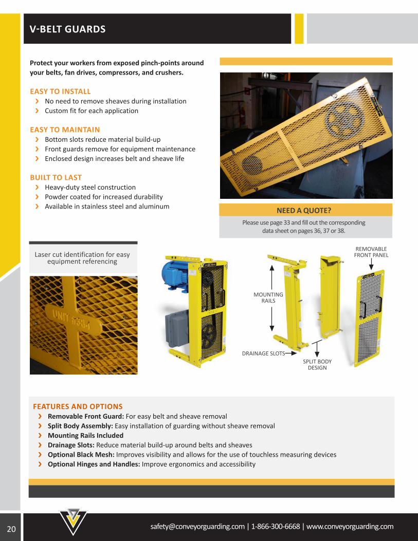
REMOVABLE FRONT PANEL
SPLIT BODYDESIGN
DRAINAGE SLOTS
MOUNTING RAILS
V-BELT GUARDS
Protect your workers from exposed pinch-points around your belts, fan drives, compressors, and crushers.
EASY TO INSTALL No need to remove sheaves during installation Custom fit for each application
EASY TO MAINTAIN Bottom slots reduce material build-up Front guards remove for equipment maintenance Enclosed design increases belt and sheave life
BUILT TO LAST Heavy-duty steel construction Powder coated for increased durability Available in stainless steel and aluminum
FEATURES AND OPTIONS Removable Front Guard: For easy belt and sheave removal Split Body Assembly: Easy installation of guarding without sheave removal Mounting Rails Included Drainage Slots: Reduce material build-up around belts and sheaves Optional Black Mesh: Improves visibility and allows for the use of touchless measuring devices Optional Hinges and Handles: Improve ergonomics and accessibility
Laser cut identification for easy equipment referencing
NEED A QUOTE? Please use page 33 and fill out the corresponding
data sheet on pages 36, 37 or 38.
[email protected] | 1-866-300-6668 | www.conveyorguarding.com
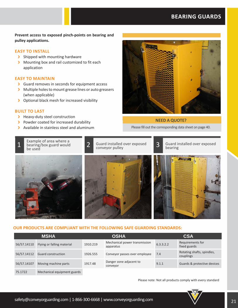
BEARING GUARDS
OUR PRODUCTS ARE COMPLIANT WITH THE FOLLOWING SAFE GUARDING STANDARDS:
Prevent access to exposed pinch-points on bearing and pulley applications.
EASY TO INSTALL Shipped with mounting hardware Mounting box and rail customized to fit each application
EASY TO MAINTAIN Guard removes in seconds for equipment access Multiple holes to mount grease lines or auto greasers (when applicable) Optional black mesh for increased visibility
BUILT TO LAST Heavy-duty steel construction Powder coated for increased durability Available in stainless steel and aluminum
Example of area where abearing/box guard wouldbe used
Guard installed over exposed bearing
Guard installed over exposed conveyor pulley1 32
MSHA OSHA CSA56/57.14110 Flying or falling material 1910.219 Mechanical power transmission
apparatus 6.3.3.2.2 Requirements for fixed guards
56/57.14112 Guard construction 1926.555 Conveyor passes over employee 7.4 Rotating shafts, spindles, couplings
56/57.14107 Moving machine parts 1917.48 Danger zone adjacent to conveyor 9.1.1 Guards & protective devices
75.1722 Mechanical equipment guards
Please note: Not all products comply with every standard
NEED A QUOTE? Please fill out the corresponding data sheet on page 40.
22 [email protected] | 1-866-300-6668 | www.conveyorguarding.com
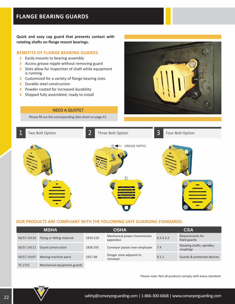
FLANGE BEARING GUARDS
OUR PRODUCTS ARE COMPLIANT WITH THE FOLLOWING SAFE GUARDING STANDARDS:
MSHA OSHA CSA56/57.14110 Flying or falling material 1910.219 Mechanical power transmission
apparatus 6.3.3.2.2 Requirements for fixed guards
56/57.14112 Guard construction 1926.555 Conveyor passes over employee 7.4 Rotating shafts, spindles, couplings
56/57.14107 Moving machine parts 1917.48 Danger zone adjacent to conveyor 9.1.1 Guards & protective devices
75.1722 Mechanical equipment guards
Quick and easy cap guard that prevents contact with rotating shafts on flange mount bearings.
BENEFITS OF FLANGE BEARING GUARDS Easily mounts to bearing assembly Access grease nipple without removing guard Slots allow for inspection of shaft while equipment is running Customized for a variety of flange bearing sizes Durable steel construction Powder coated for increased durability Shipped fully assembled, ready to install
Two Bolt Option Three Bolt Option Four Bolt Option321
Please note: Not all products comply with every standard
GREASE NIPPLE
NEED A QUOTE? Please fill out the corresponding data sheet on page 41.
[email protected] | 1-866-300-6668 | www.conveyorguarding.com
RETURN IDLER BASKETS
12” RETURN IDLER BASKET
B(BELT WIDTH)
PART NUMBER
A(BASKET WIDTH)
C(BASKET LENGTH)
18” Belt 71224N 12” 24.875”
24” Belt 70154N 12” 30.875”
30” Belt 70152N 12” 36.875”
36” Belt 70155N 12” 42.875”
42” Belt 70156N 12” 48.875”
48” Belt 70157N 12” 54.875”
54” Belt 70158N 12” 60.875”
60” Belt 70159N 12” 66.875”
66” Belt 71077N 12” 72.875”
72” Belt 71078N 12” 78.875”
78” Belt 71079N 12” 84.875”
84” Belt 71080N 12” 90.875”
90” Belt 71081N 12” 96.875”
96” Belt 71082N 12” 102.875”
24” RETURN IDLER BASKET
B(BELT WIDTH)
PART NUMBER
A(BASKET WIDTH)
C(BASKET LENGTH)
18” Belt 71225N 24” 24.875”
24” Belt 70160N 24” 30.875”
30” Belt 70161N 24” 36.875”
36” Belt 70162N 24” 42.875”
42” Belt 70163N 24” 48.875”
48” Belt 70164N 24” 54.875”
54” Belt 70165N 24” 60.875”
60” Belt 70166N 24” 66.875”
66” Belt 71092N 24” 72.875”
72” Belt 71093N 24” 78.875”
78” Belt 71094N 24” 84.875”
84” Belt 71095N 24” 90.875”
90” Belt 71096N 24” 96.875”
96” Belt 71097N 24” 102.875”
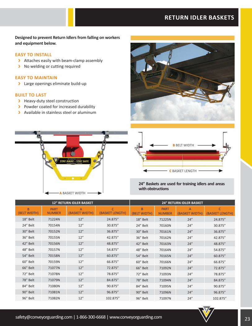
Designed to prevent Return Idlers from falling on workers and equipment below.
EASY TO INSTALL Attaches easily with beam-clamp assembly No welding or cutting required
EASY TO MAINTAIN Large openings eliminate build-up
BUILT TO LAST Heavy-duty steel construction Powder coated for increased durability Available in stainless steel or aluminum
A BASKET WIDTH
B BELT WIDTH
C BASKET LENGTH
24” Baskets are used for training idlers and areas with obstructions
24 [email protected] | 1-866-300-6668 | www.conveyorguarding.com
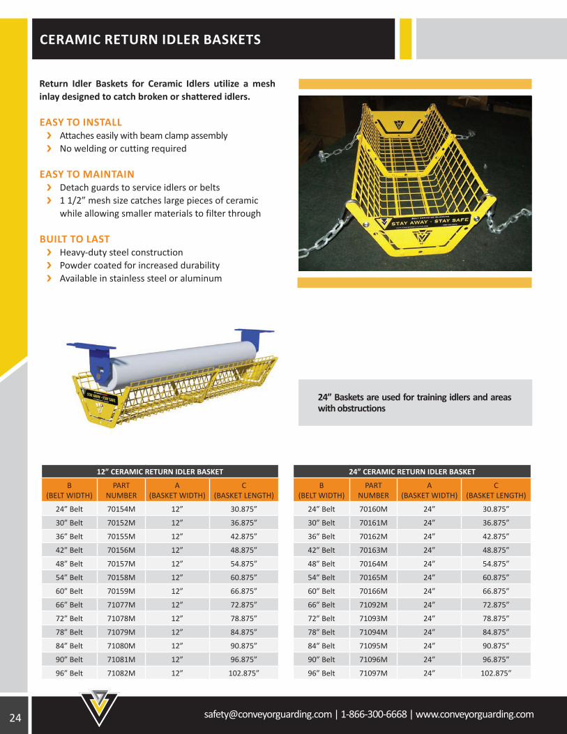
24” Baskets are used for training idlers and areas with obstructions
CERAMIC RETURN IDLER BASKETS
Return Idler Baskets for Ceramic Idlers utilize a mesh inlay designed to catch broken or shattered idlers.
EASY TO INSTALL Attaches easily with beam clamp assembly No welding or cutting required
EASY TO MAINTAIN Detach guards to service idlers or belts 1 1/2” mesh size catches large pieces of ceramic while allowing smaller materials to filter through
BUILT TO LAST Heavy-duty steel construction Powder coated for increased durability Available in stainless steel or aluminum
24” CERAMIC RETURN IDLER BASKET
B(BELT WIDTH)
PART NUMBER
A(BASKET WIDTH)
C(BASKET LENGTH)
24” Belt 70160M 24” 30.875”
30” Belt 70161M 24” 36.875”
36” Belt 70162M 24” 42.875”
42” Belt 70163M 24” 48.875”
48” Belt 70164M 24” 54.875”
54” Belt 70165M 24” 60.875”
60” Belt 70166M 24” 66.875”
66” Belt 71092M 24” 72.875”
72” Belt 71093M 24” 78.875”
78” Belt 71094M 24” 84.875”
84” Belt 71095M 24” 90.875”
90” Belt 71096M 24” 96.875”
96” Belt 71097M 24” 102.875”
12” CERAMIC RETURN IDLER BASKET
B(BELT WIDTH)
PART NUMBER
A(BASKET WIDTH)
C(BASKET LENGTH)
24” Belt 70154M 12” 30.875”
30” Belt 70152M 12” 36.875”
36” Belt 70155M 12” 42.875”
42” Belt 70156M 12” 48.875”
48” Belt 70157M 12” 54.875”
54” Belt 70158M 12” 60.875”
60” Belt 70159M 12” 66.875”
66” Belt 71077M 12” 72.875”
72” Belt 71078M 12” 78.875”
78” Belt 71079M 12” 84.875”
84” Belt 71080M 12” 90.875”
90” Belt 71081M 12” 96.875”
96” Belt 71082M 12” 102.875”
[email protected] | 1-866-300-6668 | www.conveyorguarding.com
RETURN IDLER GUARDS
RETURN IDLER GUARDS
B(BELT WIDTH)
PART NUMBER
A(GUARD WIDTH)
C(GUARD LENGTH)
D(BOLT SPACING)
24” Belt 71198 25” 40 1/2” 33”
30” Belt 71199 25” 46 1/2” 39”
36” Belt 71200 25” 52 1/2” 45”
42” Belt 71201 25” 58 1/2” 51”
48” Belt 71202 25” 64 1/2” 57”
54” Belt 71203 25” 70 1/2” 63”
60” Belt 71204 25” 76 1/2” 69”
66” Belt 71205 25” 82 1/2” 75”
72” Belt 71206 25” 88 1/2” 81”
78” Belt 71207 25” 94 1/2” 87”
84” Belt 71208 25” 100 1/2” 93”
90” Belt 71209 25” 106 1/2” 99”
96” Belt 71210 25” 112 1/2” 105”
102” Belt 71211 25” 118 1/2” 111”
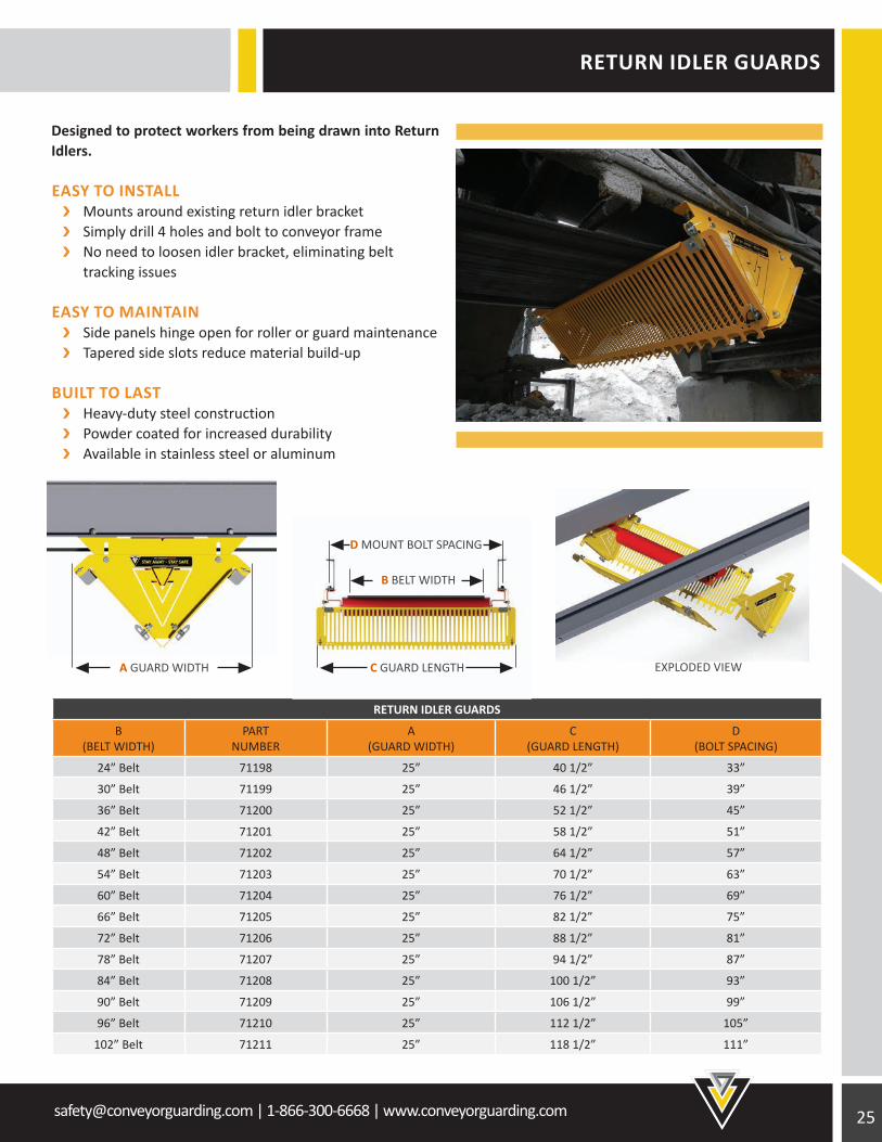
Designed to protect workers from being drawn into Return Idlers.
EASY TO INSTALL Mounts around existing return idler bracket Simply drill 4 holes and bolt to conveyor frame No need to loosen idler bracket, eliminating belt tracking issues
EASY TO MAINTAIN Side panels hinge open for roller or guard maintenance Tapered side slots reduce material build-up
BUILT TO LAST Heavy-duty steel construction Powder coated for increased durability Available in stainless steel or aluminum
B BELT WIDTH
D MOUNT BOLT SPACING
A GUARD WIDTH C GUARD LENGTH EXPLODED VIEW
26 [email protected] | 1-866-300-6668 | www.conveyorguarding.com
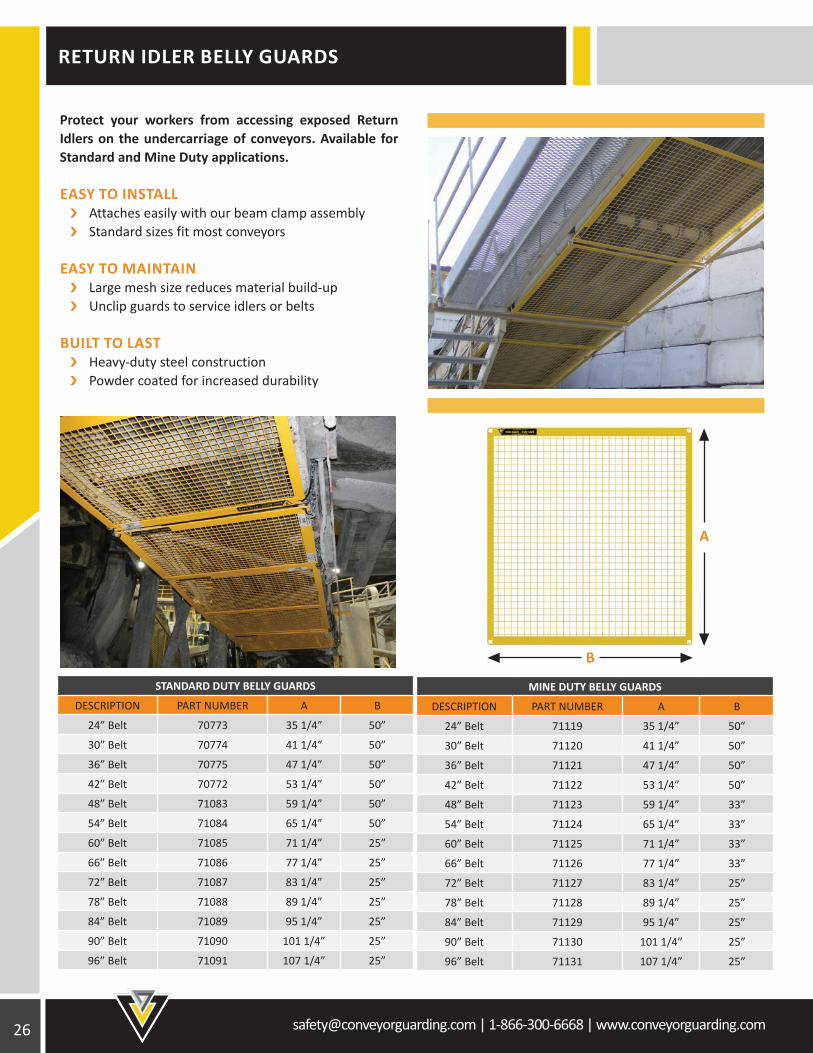
STANDARD DUTY BELLY GUARDS
DESCRIPTION PART NUMBER A B
24” Belt 70773 35 1/4” 50”
30” Belt 70774 41 1/4” 50”
36” Belt 70775 47 1/4” 50”
42” Belt 70772 53 1/4” 50”
48” Belt 71083 59 1/4” 50”
54” Belt 71084 65 1/4” 50”
60” Belt 71085 71 1/4” 25”
66” Belt 71086 77 1/4” 25”
72” Belt 71087 83 1/4” 25”
78” Belt 71088 89 1/4” 25”
84” Belt 71089 95 1/4” 25”
90” Belt 71090 101 1/4” 25”
96” Belt 71091 107 1/4” 25”
MINE DUTY BELLY GUARDS
DESCRIPTION PART NUMBER A B
24” Belt 71119 35 1/4” 50”
30” Belt 71120 41 1/4” 50”
36” Belt 71121 47 1/4” 50”
42” Belt 71122 53 1/4” 50”
48” Belt 71123 59 1/4” 33”
54” Belt 71124 65 1/4” 33”
60” Belt 71125 71 1/4” 33”
66” Belt 71126 77 1/4” 33”
72” Belt 71127 83 1/4” 25”
78” Belt 71128 89 1/4” 25”
84” Belt 71129 95 1/4” 25”
90” Belt 71130 101 1/4” 25”
96” Belt 71131 107 1/4” 25”
Protect your workers from accessing exposed Return Idlers on the undercarriage of conveyors. Available for Standard and Mine Duty applications.
EASY TO INSTALL Attaches easily with our beam clamp assembly Standard sizes fit most conveyors
EASY TO MAINTAIN Large mesh size reduces material build-up Unclip guards to service idlers or belts
BUILT TO LAST Heavy-duty steel construction Powder coated for increased durability
RETURN IDLER BELLY GUARDS
B
A
[email protected] | 1-866-300-6668 | www.conveyorguarding.com
MSHA OSHA CSA56/57.14110 Flying or falling material 1910.219 Mechanical power transmission
apparatus 6.3.3.2.2 Requirements for fixed guards
56/57.14112 Guard construction 1926.555 Conveyor passes over employee 7.4 Rotating shafts, spindles, couplings
56/57.14107 Moving machine parts 1917.48 Danger zone adjacent to conveyor 9.1.1 Guards & protective devices
75.1722 Mechanical equipment guards
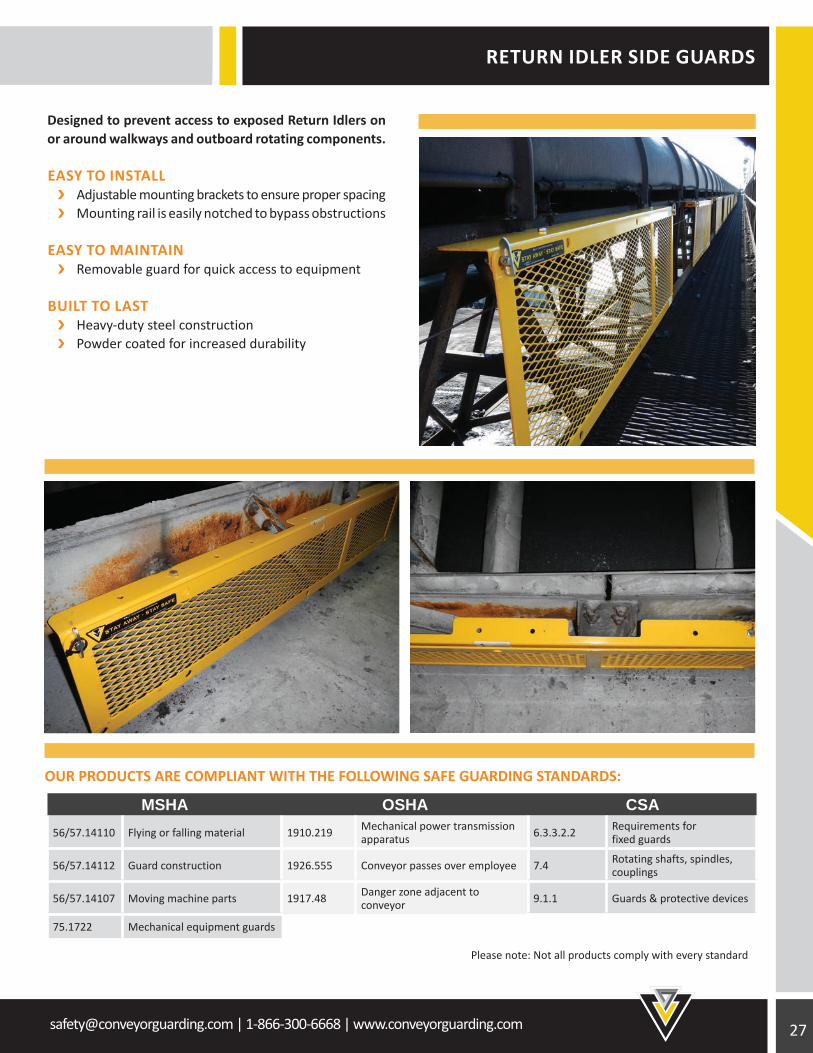
RETURN IDLER SIDE GUARDS
Designed to prevent access to exposed Return Idlers on or around walkways and outboard rotating components.
EASY TO INSTALL Adjustable mounting brackets to ensure proper spacing Mounting rail is easily notched to bypass obstructions
EASY TO MAINTAIN Removable guard for quick access to equipment
BUILT TO LAST Heavy-duty steel construction Powder coated for increased durability
OUR PRODUCTS ARE COMPLIANT WITH THE FOLLOWING SAFE GUARDING STANDARDS:
Please note: Not all products comply with every standard
28 [email protected] | 1-866-300-6668 | www.conveyorguarding.com
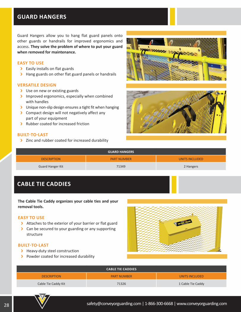
Guard Hangers allow you to hang flat guard panels onto other guards or handrails for improved ergonomics and access. They solve the problem of where to put your guard when removed for maintenance.
EASY TO USE Easily installs on flat guards Hang guards on other flat guard panels or handrails
VERSATILE DESIGN Use on new or existing guards Improved ergonomics, especially when combined with handles Unique non-slip design ensures a tight fit when hanging Compact design will not negatively affect any part of your equipment Rubber coated for increased friction
BUILT-TO-LAST Zinc and rubber coated for increased durability
The Cable Tie Caddy organizes your cable ties and your removal tools.
EASY TO USE Attaches to the exterior of your barrier or flat guard Can be secured to your guarding or any supporting structure
BUILT-TO-LAST Heavy-duty steel construction Powder coated for increased durability
CABLE TIE CADDIES
DESCRIPTION PART NUMBER UNITS INCLUDED
Cable Tie Caddy Kit 71326 1 Cable Tie Caddy
GUARD HANGERS
DESCRIPTION PART NUMBER UNITS INCLUDED
Guard Hanger Kit 71349 2 Hangers
GUARD HANGERS
CABLE TIE CADDIES

[email protected] | 1-866-300-6668 | www.conveyorguarding.com
HANDLES
HANDLES
DESCRIPTION PART NUMBER UNITS INCLUDED
Handle Kit 71303 2 Handles
EACH HANDLE KIT INCLUDES TWO HANDLES AND ALL REQUIRED MOUNTING HARDWARE
Ergonomically friendly handles for easier removal and handling of guard.
EASY TO INSTALL Universal - can be used on many applications Retrofit onto existing guards
EASY TO MAINTAIN Ergonomic design Improve handling of guards Mount in any direction for optimal grip position
BUILT TO LAST Rubber coated for added comfort Zinc plated for durability Stainless steel option available for highly corrosive applications (custom order)
RUBBER COATED HANDLES IMPROVE ERGONOMICS AND ADD COMFORT WHEN HANDLING GUARDS
HANDLES ARE EASILY MOUNTED AND ALL HARDWARE FOR MOUNTING IS PROVIDED
30 [email protected] | 1-866-300-6668 | www.conveyorguarding.com
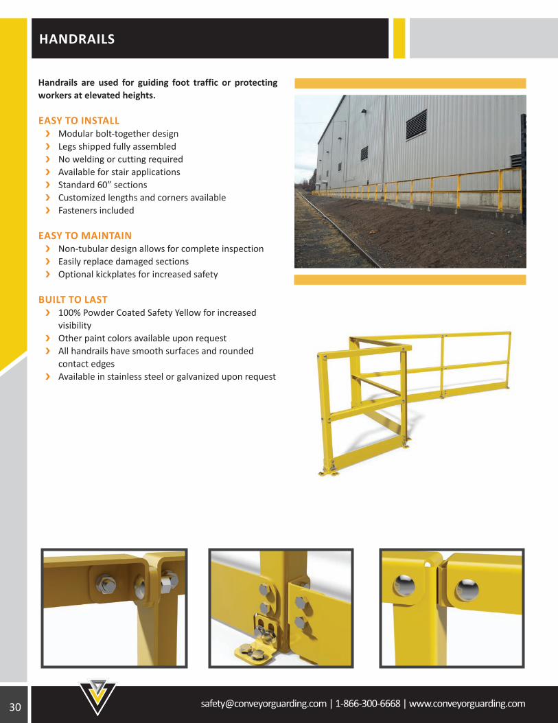
HANDRAILS
Handrails are used for guiding foot traffic or protecting workers at elevated heights.
EASY TO INSTALL Modular bolt-together design Legs shipped fully assembled No welding or cutting required Available for stair applications Standard 60” sections Customized lengths and corners available Fasteners included
EASY TO MAINTAIN Non-tubular design allows for complete inspection Easily replace damaged sections Optional kickplates for increased safety
BUILT TO LAST 100% Powder Coated Safety Yellow for increased visibility Other paint colors available upon request All handrails have smooth surfaces and rounded contact edges Available in stainless steel or galvanized upon request
[email protected] | 1-866-300-6668 | www.conveyorguarding.com
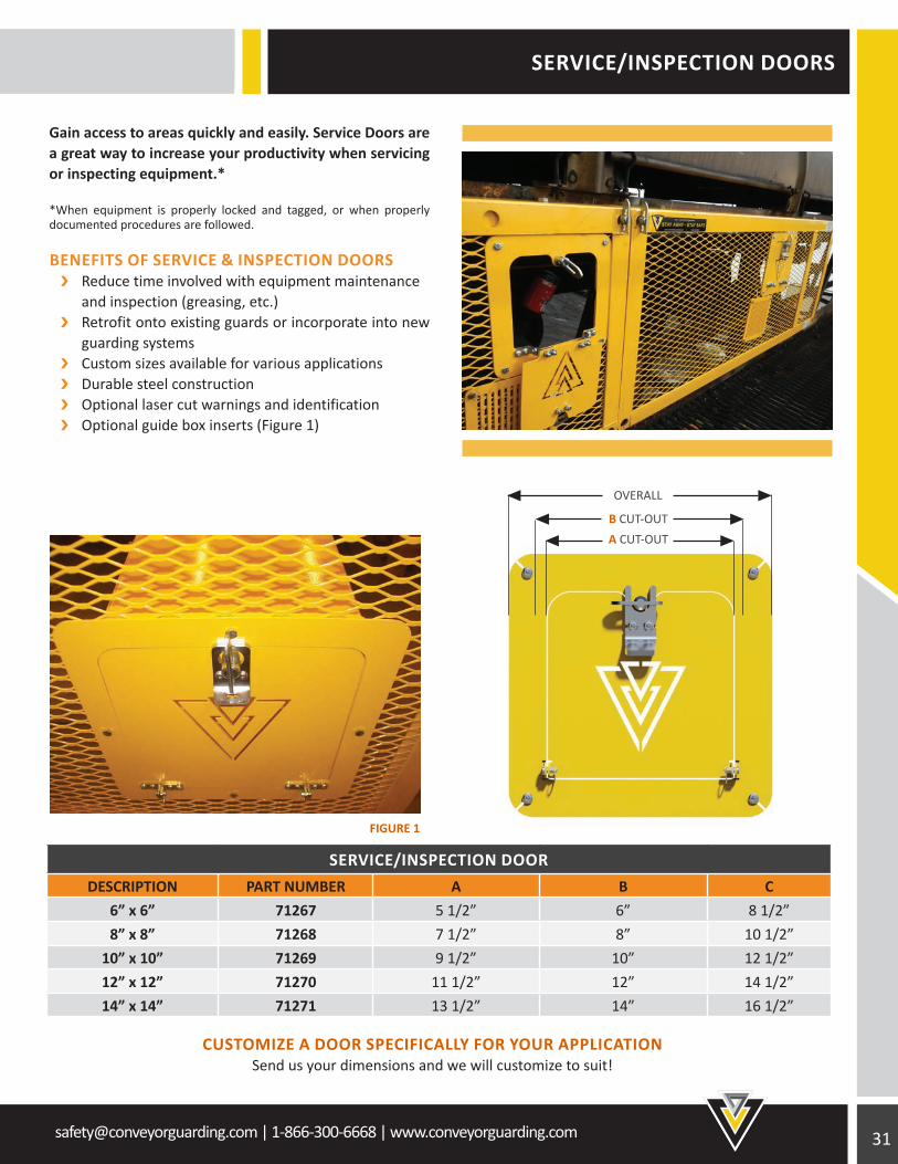
SERVICE/INSPECTION DOORS
SERVICE/INSPECTION DOORDESCRIPTION PART NUMBER A B C
6” x 6” 71267 5 1/2” 6” 8 1/2”8” x 8” 71268 7 1/2” 8” 10 1/2”
10” x 10” 71269 9 1/2” 10” 12 1/2”12” x 12” 71270 11 1/2” 12” 14 1/2”14” x 14” 71271 13 1/2” 14” 16 1/2”
Gain access to areas quickly and easily. Service Doors are a great way to increase your productivity when servicing or inspecting equipment.*
*When equipment is properly locked and tagged, or when properly documented procedures are followed.
BENEFITS OF SERVICE & INSPECTION DOORS Reduce time involved with equipment maintenance and inspection (greasing, etc.) Retrofit onto existing guards or incorporate into new guarding systems Custom sizes available for various applications Durable steel construction Optional laser cut warnings and identification Optional guide box inserts (Figure 1)
CUSTOMIZE A DOOR SPECIFICALLY FOR YOUR APPLICATIONSend us your dimensions and we will customize to suit!
OVERALL
B CUT-OUTA CUT-OUT
FIGURE 1
[email protected] | 1-866-300-6668 | www.conveyorguarding.com 32
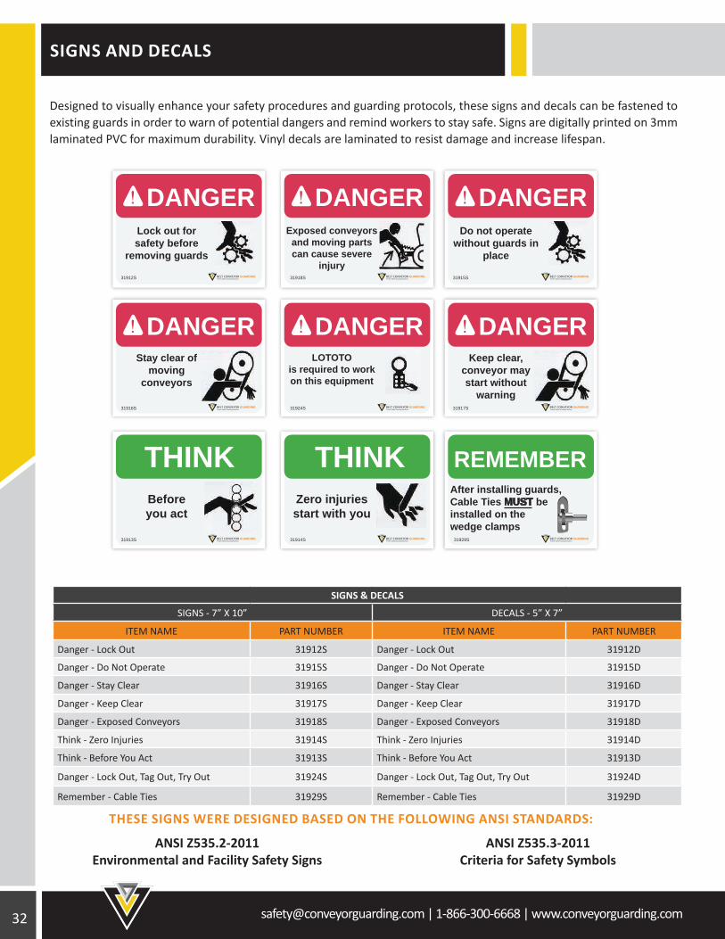
SIGNS AND DECALS
SIGNS & DECALS
SIGNS - 7” X 10” DECALS - 5” X 7”
ITEM NAME PART NUMBER ITEM NAME PART NUMBER
Danger - Lock Out 31912S Danger - Lock Out 31912D
Danger - Do Not Operate 31915S Danger - Do Not Operate 31915D
Danger - Stay Clear 31916S Danger - Stay Clear 31916D
Danger - Keep Clear 31917S Danger - Keep Clear 31917D
Danger - Exposed Conveyors 31918S Danger - Exposed Conveyors 31918D
Think - Zero Injuries 31914S Think - Zero Injuries 31914D
Think - Before You Act 31913S Think - Before You Act 31913D
Danger - Lock Out, Tag Out, Try Out 31924S Danger - Lock Out, Tag Out, Try Out 31924D
Remember - Cable Ties 31929S Remember - Cable Ties 31929D
THESE SIGNS WERE DESIGNED BASED ON THE FOLLOWING ANSI STANDARDS:
ANSI Z535.2-2011 Environmental and Facility Safety Signs
ANSI Z535.3-2011Criteria for Safety Symbols
Designed to visually enhance your safety procedures and guarding protocols, these signs and decals can be fastened to existing guards in order to warn of potential dangers and remind workers to stay safe. Signs are digitally printed on 3mm laminated PVC for maximum durability. Vinyl decals are laminated to resist damage and increase lifespan.
DANGER! DANGER! DANGER!
DANGER! DANGER! DANGER!
THINKTHINK
31912S
Lock out for safety before
removing guards
Exposed conveyors and moving parts can cause severe
injury
Do not operate without guards in
place
Stay clear of moving
conveyors
LOTOTOis required to work on this equipment
Keep clear, conveyor may start without
warning
Before you act
Zero injuries start with you
31918S 31915S
31916S 31924S 31917S
31913S 31914S
REMEMBER
31929S
After installing guards,Cable Ties MUST beinstalled on the wedge clamps
[email protected] | 1-866-300-6668 | www.conveyorguarding.com
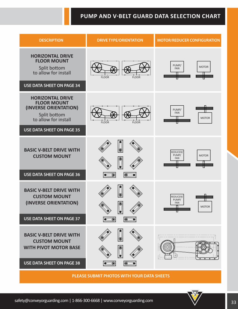
PUMP AND V-BELT GUARD DATA SELECTION CHART
USE DATA SHEET ON PAGE 34
DESCRIPTION DRIVE TYPE/ORIENTATION MOTOR/REDUCER CONFIGURATION
USE DATA SHEET ON PAGE 35
PLEASE SUBMIT PHOTOS WITH YOUR DATA SHEETS
USE DATA SHEET ON PAGE 36
USE DATA SHEET ON PAGE 37
USE DATA SHEET ON PAGE 38
HORIZONTAL DRIVE FLOOR MOUNT
Split bottom to allow for install
HORIZONTAL DRIVE FLOOR MOUNT
(INVERSE ORIENTATION)Split bottom
to allow for install
BASIC V-BELT DRIVE WITH CUSTOM MOUNT
BASIC V-BELT DRIVE WITH CUSTOM MOUNT
(INVERSE ORIENTATION)
BASIC V-BELT DRIVE WITH CUSTOM MOUNT
WITH PIVOT MOTOR BASE
FLOOR FLOOR
PUMP/FAN MOTOR
REDUCER/PUMP/
FAN
REDUCER/PUMP/
FAN
MOTOR
FLOOR FLOOR
PUMP/FAN
MOTOR
MOTOR
34 [email protected] | 1-866-300-6668 | www.conveyorguarding.com
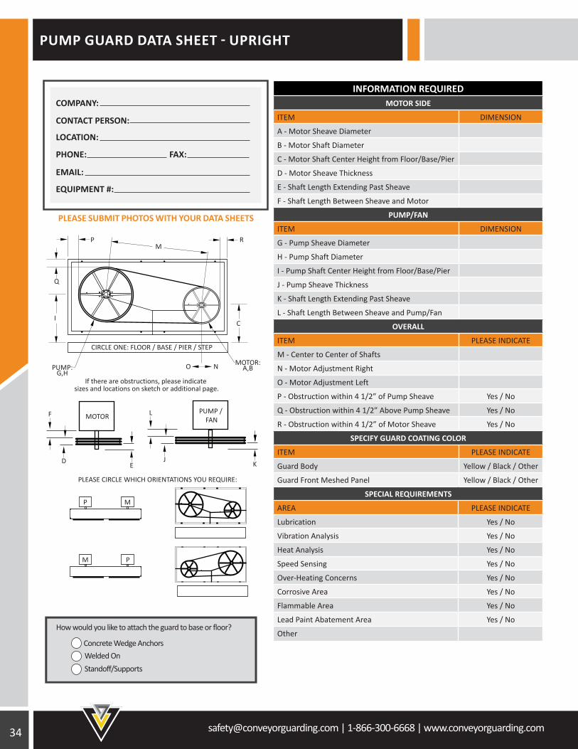
PUMP GUARD DATA SHEET - UPRIGHT
INFORMATION REQUIREDMOTOR SIDE
ITEM DIMENSION
A - Motor Sheave Diameter
B - Motor Shaft Diameter
C - Motor Shaft Center Height from Floor/Base/Pier
D - Motor Sheave Thickness
E - Shaft Length Extending Past Sheave
F - Shaft Length Between Sheave and Motor
PUMP/FAN
ITEM DIMENSION
G - Pump Sheave Diameter
H - Pump Shaft Diameter
I - Pump Shaft Center Height from Floor/Base/Pier
J - Pump Sheave Thickness
K - Shaft Length Extending Past Sheave
L - Shaft Length Between Sheave and Pump/Fan
OVERALL
ITEM PLEASE INDICATE
M - Center to Center of Shafts
N - Motor Adjustment Right
O - Motor Adjustment Left
P - Obstruction within 4 1/2” of Pump Sheave Yes / No
Q - Obstruction within 4 1/2” Above Pump Sheave Yes / No
R - Obstruction within 4 1/2” of Motor Sheave Yes / No
SPECIFY GUARD COATING COLOR
ITEM PLEASE INDICATE
Guard Body Yellow / Black / Other
Guard Front Meshed Panel Yellow / Black / Other
SPECIAL REQUIREMENTS
AREA PLEASE INDICATE
Lubrication Yes / No
Vibration Analysis Yes / No
Heat Analysis Yes / No
Speed Sensing Yes / No
Over-Heating Concerns Yes / No
Corrosive Area Yes / No
Flammable Area Yes / No
Lead Paint Abatement Area Yes / No
Other
PLEASE CIRCLE WHICH ORIENTATIONS YOU REQUIRE:
MOTOR:A,BPUMP:
G,HIf there are obstructions, please indicate
sizes and locations on sketch or additional page.
O N
CI
Q
PM
R
CIRCLE ONE: FLOOR / BASE / PIER / STEP
P M
PM
F MOTOR
ED
PUMP / FAN
K
L
J
PLEASE SUBMIT PHOTOS WITH YOUR DATA SHEETS
How would you like to attach the guard to base or floor?
Concrete Wedge Anchors
Standoff/SupportsWelded On
PHONE: FAX:
EMAIL:
EQUIPMENT #:
LOCATION:
CONTACT PERSON:
COMPANY:
[email protected] | 1-866-300-6668 | www.conveyorguarding.com
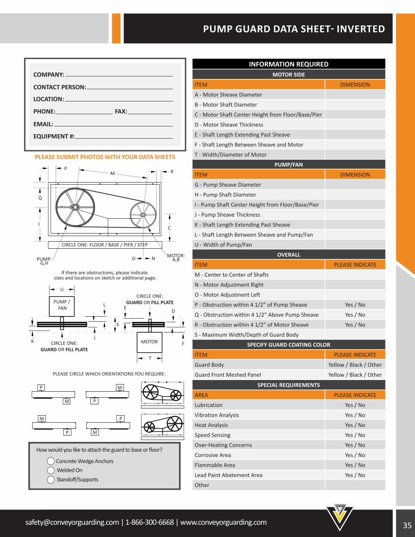
PUMP GUARD DATA SHEET- INVERTED
SPECIAL REQUIREMENTS
AREA PLEASE INDICATE
Lubrication Yes / No
Vibration Analysis Yes / No
Heat Analysis Yes / No
Speed Sensing Yes / No
Over-Heating Concerns Yes / No
Corrosive Area Yes / No
Flammable Area Yes / No
Lead Paint Abatement Area Yes / No
Other
INFORMATION REQUIREDMOTOR SIDE
ITEM DIMENSION
A - Motor Sheave Diameter
B - Motor Shaft Diameter
C - Motor Shaft Center Height from Floor/Base/Pier
D - Motor Sheave Thickness
E - Shaft Length Extending Past Sheave
F - Shaft Length Between Sheave and Motor
T - Width/Diameter of Motor
PUMP/FAN
ITEM DIMENSION
G - Pump Sheave Diameter
H - Pump Shaft Diameter
I - Pump Shaft Center Height from Floor/Base/Pier
J - Pump Sheave Thickness
K - Shaft Length Extending Past Sheave
L - Shaft Length Between Sheave and Pump/Fan
U - Width of Pump/Fan
OVERALL
ITEM PLEASE INDICATE
M - Center to Center of Shafts
N - Motor Adjustment Right
O - Motor Adjustment Left
P - Obstruction within 4 1/2” of Pump Sheave Yes / No
Q - Obstruction within 4 1/2” Above Pump Sheave Yes / No
R - Obstruction within 4 1/2” of Motor Sheave Yes / No
S - Maximum Width/Depth of Guard Body
SPECIFY GUARD COATING COLOR
ITEM PLEASE INDICATE
Guard Body Yellow / Black / Other
Guard Front Meshed Panel Yellow / Black / Other
FMOTOR
PUMP / FAN E
K
DL
CIRCLE ONE:GUARD OR FILL PLATE
J
S
MOTOR:A,BPUMP:
G,HO N
CI
Q
PM R
CIRCLE ONE: FLOOR / BASE / PIER / STEP
If there are obstructions, please indicate sizes and locations on sketch or additional page.
PLEASE CIRCLE WHICH ORIENTATIONS YOU REQUIRE:
P
PM
M
P
P M
M
T
UCIRCLE ONE:
GUARD OR FILL PLATE
How would you like to attach the guard to base or floor?
Concrete Wedge Anchors
Standoff/SupportsWelded On
PLEASE SUBMIT PHOTOS WITH YOUR DATA SHEETS
PHONE: FAX:
EMAIL:
EQUIPMENT #:
LOCATION:
CONTACT PERSON:
COMPANY:

36 [email protected] | 1-866-300-6668 | www.conveyorguarding.com
V-BELT GUARD DATA SHEET - UPRIGHT
SPECIAL REQUIREMENTS
AREA PLEASE INDICATE
Lubrication Yes / No
Vibration Analysis Yes / No
Heat Analysis Yes / No
Speed Sensing Yes / No
Over-Heating Concerns Yes / No
Corrosive Area Yes / No
Flammable Area Yes / No
Lead Paint Abatement Area Yes / No
Motor Adjustments in/out (+/-)
Other
INFORMATION REQUIREDMOTOR SIDE
ITEM DIMENSION
A - Motor Sheave Diameter
B - Motor Shaft Diameter
C - Motor Sheave Thickness
D - Shaft Length Extending Past Sheave
E - Shaft Length Between Sheave and Motor
REDUCER/PUMP/FAN
ITEM DIMENSION
F - Reducer Sheave Diameter
G - Reducer Shaft Diameter
H - Reducer Sheave Thickness
I - Shaft Length Extending Past Sheave
J - Shaft Length Between Sheave and Reducer
OVERALL
ITEM PLEASE INDICATE
K - Center to Center of Shafts
L - Obstruction within 4 1/2” of Reducer Sheave Yes / No
M - Obstruction within 4 1/2” of Motor Sheave Yes / No
N - Obstruction within 4 1/2” of Largest Sheave Yes / No
Speed Reducer Yes / No
EXTRA INFORMATION
ITEM PLEASE INDICATE
O - Distance to Reducer Sheave Obstruction
P - Distance to Motor Sheave Obstruction
Q - Distance to Reducer Sheave Obstruction
R - Distance to Motor Sheave Obstruction
SPECIFY GUARD COATING COLOR
ITEM PLEASE INDICATE
Guard Body Yellow / Black / Other
Guard Front Mesh Panel Yellow / Black / Other
REDUCER/PUMP/FANF,G
MOTOR:A,B
M
R
P
Q
ON
N
L
K
If there are obstructions, please indicate sizes, locations, and the distances from sheave(s) on the above sketch or additional page.
Please circle the correct orientation ofyour equipment and indicate top location
E
MO
TOR
REDUCER /
PUM
P / FAN
D
I
C
J
H
PLEASE SUBMIT PHOTOS WITH YOUR DATA SHEETS
PHONE: FAX:
EMAIL:
EQUIPMENT #:
LOCATION:
CONTACT PERSON:
COMPANY:
[email protected] | 1-866-300-6668 | www.conveyorguarding.com
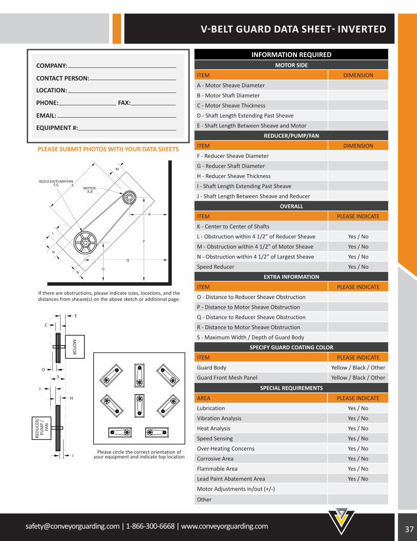
V-BELT GUARD DATA SHEET- INVERTED
SPECIAL REQUIREMENTS
AREA PLEASE INDICATE
Lubrication Yes / No
Vibration Analysis Yes / No
Heat Analysis Yes / No
Speed Sensing Yes / No
Over-Heating Concerns Yes / No
Corrosive Area Yes / No
Flammable Area Yes / No
Lead Paint Abatement Area Yes / No
Motor Adjustments in/out (+/-)
Other
INFORMATION REQUIREDMOTOR SIDE
ITEM DIMENSION
A - Motor Sheave Diameter
B - Motor Shaft Diameter
C - Motor Sheave Thickness
D - Shaft Length Extending Past Sheave
E - Shaft Length Between Sheave and Motor
REDUCER/PUMP/FAN
ITEM DIMENSION
F - Reducer Sheave Diameter
G - Reducer Shaft Diameter
H - Reducer Sheave Thickness
I - Shaft Length Extending Past Sheave
J - Shaft Length Between Sheave and Reducer
OVERALL
ITEM PLEASE INDICATE
K - Center to Center of Shafts
L - Obstruction within 4 1/2” of Reducer Sheave Yes / No
M - Obstruction within 4 1/2” of Motor Sheave Yes / No
N - Obstruction within 4 1/2” of Largest Sheave Yes / No
Speed Reducer Yes / No
EXTRA INFORMATION
ITEM PLEASE INDICATE
O - Distance to Reducer Sheave Obstruction
P - Distance to Motor Sheave Obstruction
Q - Distance to Reducer Sheave Obstruction
R - Distance to Motor Sheave Obstruction
S - Maximum Width / Depth of Guard Body
SPECIFY GUARD COATING COLOR
ITEM PLEASE INDICATE
Guard Body Yellow / Black / Other
Guard Front Mesh Panel Yellow / Black / Other
E
MO
TOR
REDU
CER/
PU
MP
/ FA
N
D
I
C
J
H
S
REDUCER/PUMP/FANF,G
MOTOR:A,B
M
R
P
Q
ON
N
L
K
If there are obstructions, please indicate sizes, locations, and the distances from sheave(s) on the above sketch or additional page.
Please circle the correct orientation ofyour equipment and indicate top location
PLEASE SUBMIT PHOTOS WITH YOUR DATA SHEETS
PHONE: FAX:
EMAIL:
EQUIPMENT #:
LOCATION:
CONTACT PERSON:
COMPANY:
38 [email protected] | 1-866-300-6668 | www.conveyorguarding.com
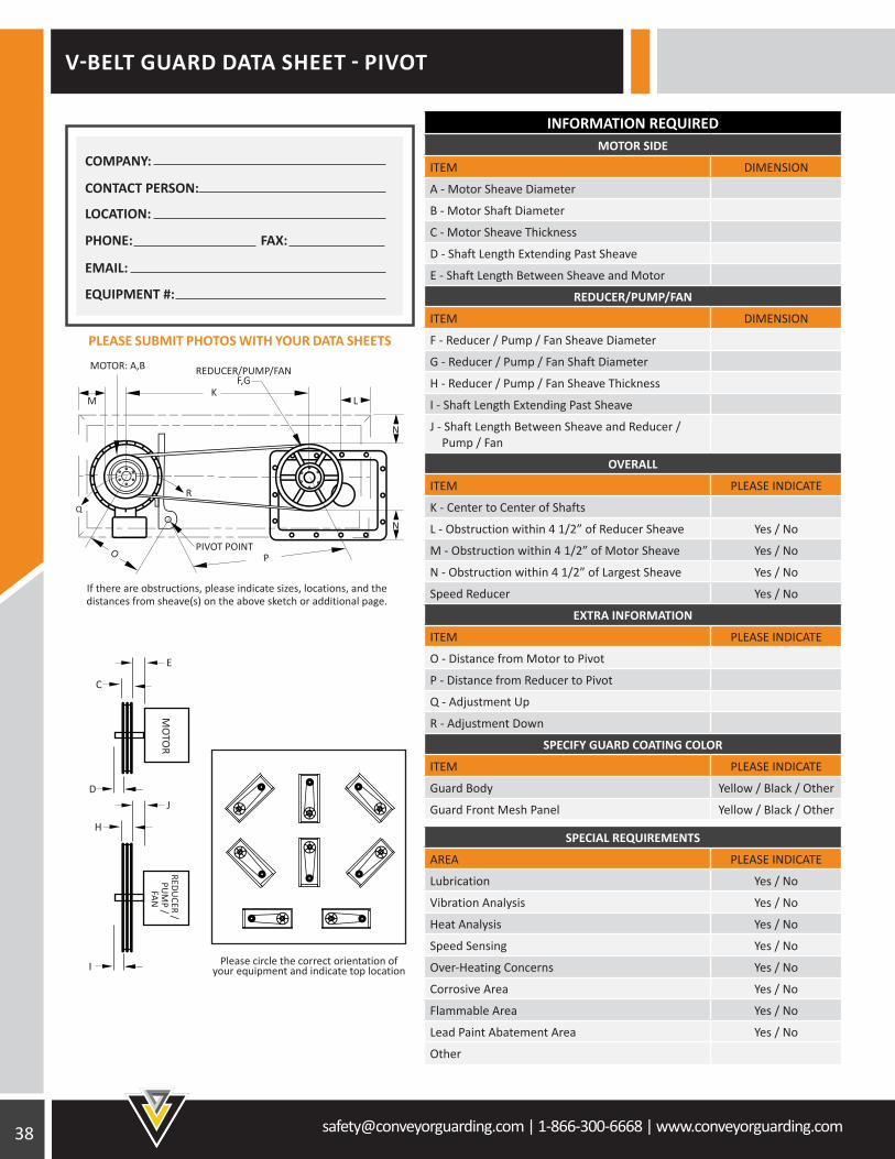
V-BELT GUARD DATA SHEET - PIVOT
SPECIAL REQUIREMENTS
AREA PLEASE INDICATE
Lubrication Yes / No
Vibration Analysis Yes / No
Heat Analysis Yes / No
Speed Sensing Yes / No
Over-Heating Concerns Yes / No
Corrosive Area Yes / No
Flammable Area Yes / No
Lead Paint Abatement Area Yes / No
Other
INFORMATION REQUIREDMOTOR SIDE
ITEM DIMENSION
A - Motor Sheave Diameter
B - Motor Shaft Diameter
C - Motor Sheave Thickness
D - Shaft Length Extending Past Sheave
E - Shaft Length Between Sheave and Motor
REDUCER/PUMP/FAN
ITEM DIMENSION
F - Reducer / Pump / Fan Sheave Diameter
G - Reducer / Pump / Fan Shaft Diameter
H - Reducer / Pump / Fan Sheave Thickness
I - Shaft Length Extending Past Sheave
J - Shaft Length Between Sheave and Reducer / Pump / Fan
OVERALL
ITEM PLEASE INDICATE
K - Center to Center of Shafts
L - Obstruction within 4 1/2” of Reducer Sheave Yes / No
M - Obstruction within 4 1/2” of Motor Sheave Yes / No
N - Obstruction within 4 1/2” of Largest Sheave Yes / No
Speed Reducer Yes / No
EXTRA INFORMATION
ITEM PLEASE INDICATE
O - Distance from Motor to Pivot
P - Distance from Reducer to Pivot
Q - Adjustment Up
R - Adjustment Down
SPECIFY GUARD COATING COLOR
ITEM PLEASE INDICATE
Guard Body Yellow / Black / Other
Guard Front Mesh Panel Yellow / Black / Other
If there are obstructions, please indicate sizes, locations, and the distances from sheave(s) on the above sketch or additional page.
Please circle the correct orientation ofyour equipment and indicate top location
E
MO
TOR
REDUCER /
PUM
P / FAN
D
I
C
J
H
K
N
O P
N
LM
Q
R
REDUCER/PUMP/FANF,G
MOTOR: A,B
PIVOT POINT
PLEASE SUBMIT PHOTOS WITH YOUR DATA SHEETS
PHONE: FAX:
EMAIL:
EQUIPMENT #:
LOCATION:
CONTACT PERSON:
COMPANY:
[email protected] | 1-866-300-6668 | www.conveyorguarding.com
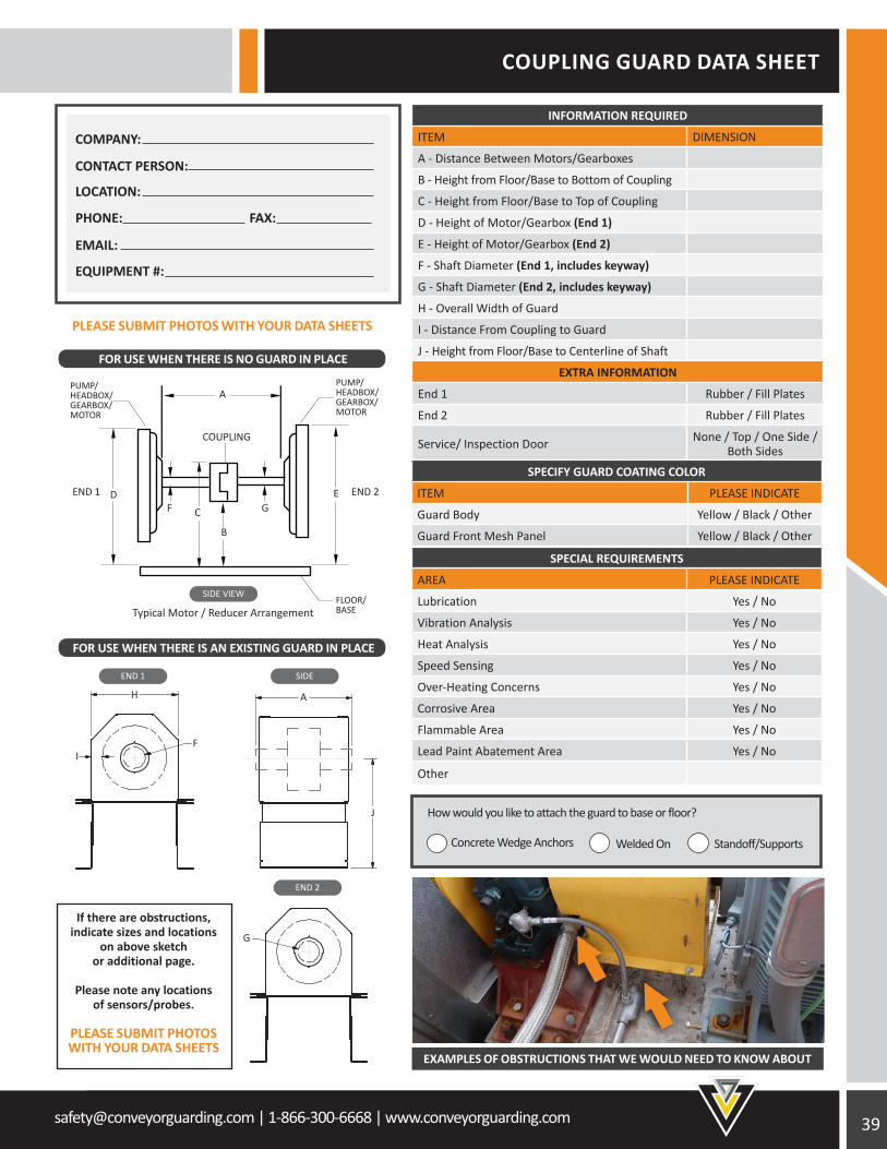
COUPLING GUARD DATA SHEET
Typical Motor / Reducer Arrangement
A
E
B
GF C
D
COUPLING
PUMP/HEADBOX/GEARBOX/MOTOR
PUMP/HEADBOX/GEARBOX/MOTOR
FLOOR/BASE
SIDE VIEW
END 1 SIDE
END 2END 1
A
J
END 2
G
H
FI
FOR USE WHEN THERE IS NO GUARD IN PLACE
FOR USE WHEN THERE IS AN EXISTING GUARD IN PLACE
PLEASE SUBMIT PHOTOS WITH YOUR DATA SHEETS
How would you like to attach the guard to base or floor?
Concrete Wedge Anchors Standoff/SupportsWelded On
INFORMATION REQUIRED
ITEM DIMENSION
A - Distance Between Motors/Gearboxes
B - Height from Floor/Base to Bottom of Coupling
C - Height from Floor/Base to Top of Coupling
D - Height of Motor/Gearbox (End 1)
E - Height of Motor/Gearbox (End 2)
F - Shaft Diameter (End 1, includes keyway)
G - Shaft Diameter (End 2, includes keyway)
H - Overall Width of Guard
I - Distance From Coupling to Guard
J - Height from Floor/Base to Centerline of Shaft
EXTRA INFORMATION
End 1 Rubber / Fill Plates
End 2 Rubber / Fill Plates
Service/ Inspection Door None / Top / One Side / Both Sides
SPECIAL REQUIREMENTS
AREA PLEASE INDICATE
Lubrication Yes / No
Vibration Analysis Yes / No
Heat Analysis Yes / No
Speed Sensing Yes / No
Over-Heating Concerns Yes / No
Corrosive Area Yes / No
Flammable Area Yes / No
Lead Paint Abatement Area Yes / No
Other
SPECIFY GUARD COATING COLOR
ITEM PLEASE INDICATE
Guard Body Yellow / Black / Other
Guard Front Mesh Panel Yellow / Black / Other
If there are obstructions, indicate sizes and locations
on above sketch or additional page.
Please note any locations of sensors/probes.
PLEASE SUBMIT PHOTOS WITH YOUR DATA SHEETS
EXAMPLES OF OBSTRUCTIONS THAT WE WOULD NEED TO KNOW ABOUT
PHONE: FAX:
EMAIL:
EQUIPMENT #:
LOCATION:
CONTACT PERSON:
COMPANY:
40 [email protected] | 1-866-300-6668 | www.conveyorguarding.com
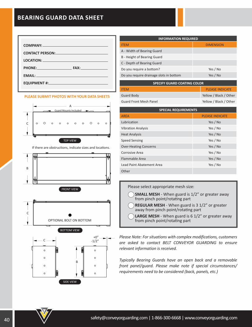
TOP VIEW
FRONT VIEW
BOTTOM VIEW
SIDE VIEW
C
OPTIONAL BOLT ON BOTTOM
B
+0”-1/2”
A
If there are obstructions, indicate sizes and locations.
C
B
C
Guard Mounts Included
BEARING GUARD DATA SHEET
INFORMATION REQUIRED
ITEM DIMENSION
A - Width of Bearing Guard
B - Height of Bearing Guard
C - Depth of Bearing Guard
Do you require a bottom? Yes / No
Do you require drainage slots in bottom Yes / No
SPECIAL REQUIREMENTS
AREA PLEASE INDICATE
Lubrication Yes / No
Vibration Analysis Yes / No
Heat Analysis Yes / No
Speed Sensing Yes / No
Over-Heating Concerns Yes / No
Corrosive Area Yes / No
Flammable Area Yes / No
Lead Paint Abatement Area Yes / No
Other
Please select appropriate mesh size:
Please Note: For situations with complex modifications, customers are asked to contact BELT CONVEYOR GUARDING to ensure relevant information is received.
Typically Bearing Guards have an open back and a removable front panel/guard. Please make note if special circumstances/requirements need to be considered (back, panels, etc.)
PLEASE SUBMIT PHOTOS WITH YOUR DATA SHEETS
SPECIFY GUARD COATING COLOR
ITEM PLEASE INDICATE
Guard Body Yellow / Black / Other
Guard Front Mesh Panel Yellow / Black / Other
PHONE: FAX:
EMAIL:
EQUIPMENT #:
LOCATION:
CONTACT PERSON:
COMPANY:
[email protected] | 1-866-300-6668 | www.conveyorguarding.com
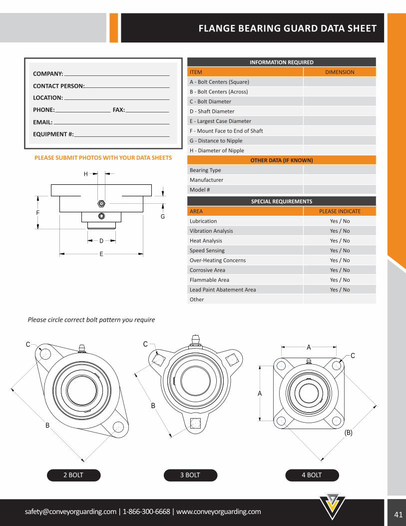
FLANGE BEARING GUARD DATA SHEET
SPECIAL REQUIREMENTS
AREA PLEASE INDICATE
Lubrication Yes / No
Vibration Analysis Yes / No
Heat Analysis Yes / No
Speed Sensing Yes / No
Over-Heating Concerns Yes / No
Corrosive Area Yes / No
Flammable Area Yes / No
Lead Paint Abatement Area Yes / No
Other
INFORMATION REQUIRED
ITEM DIMENSION
A - Bolt Centers (Square)
B - Bolt Centers (Across)
C - Bolt Diameter
D - Shaft Diameter
E - Largest Case Diameter
F - Mount Face to End of Shaft
G - Distance to Nipple
H - Diameter of Nipple
OTHER DATA (IF KNOWN)
Bearing Type
Manufacturer
Model #
SCALE 1:3
F
D
E
G
H
SCALE 1 / 2
B
C
SCALE 1:3
(B)
A
AC
SCALE 2/3
B
C
Please circle correct bolt pattern you require
2 BOLT 3 BOLT 4 BOLT
PLEASE SUBMIT PHOTOS WITH YOUR DATA SHEETS
PHONE: FAX:
EMAIL:
EQUIPMENT #:
LOCATION:
CONTACT PERSON:
COMPANY:
INFORMATION REQUIRED
ITEM DIMENSION
A - Width of Bearing Guard
B - Height of Bearing Guard
C - Depth of Bearing Guard
Do you require a bottom? Yes / No
Do you require drainage slots in bottom Yes / No
42 [email protected] | 1-866-300-6668 | www.conveyorguarding.com
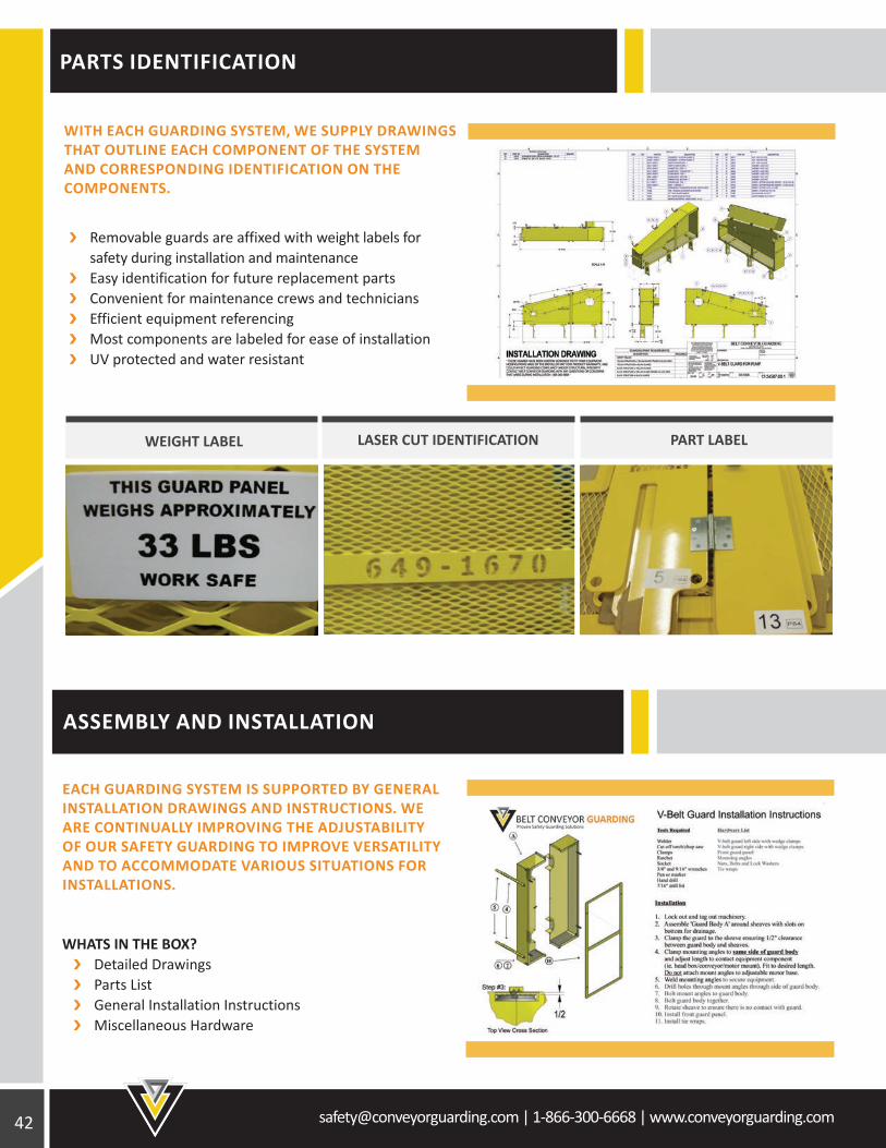
PARTS IDENTIFICATION
ASSEMBLY AND INSTALLATION
WITH EACH GUARDING SYSTEM, WE SUPPLY DRAWINGS THAT OUTLINE EACH COMPONENT OF THE SYSTEM AND CORRESPONDING IDENTIFICATION ON THE COMPONENTS.
EACH GUARDING SYSTEM IS SUPPORTED BY GENERAL INSTALLATION DRAWINGS AND INSTRUCTIONS. WE ARE CONTINUALLY IMPROVING THE ADJUSTABILITY OF OUR SAFETY GUARDING TO IMPROVE VERSATILITY AND TO ACCOMMODATE VARIOUS SITUATIONS FOR INSTALLATIONS.
Removable guards are affixed with weight labels for safety during installation and maintenance Easy identification for future replacement parts Convenient for maintenance crews and technicians Efficient equipment referencing Most components are labeled for ease of installation UV protected and water resistant
WHATS IN THE BOX? Detailed Drawings Parts List General Installation Instructions Miscellaneous Hardware
LASER CUT IDENTIFICATION PART LABELWEIGHT LABEL
[email protected] | 1-866-300-6668 | www.conveyorguarding.com
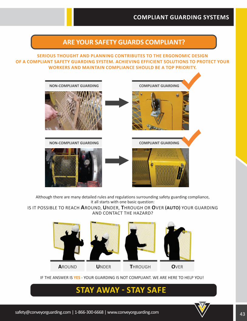
SERIOUS THOUGHT AND PLANNING CONTRIBUTES TO THE ERGONOMIC DESIGN OF A COMPLIANT SAFETY GUARDING SYSTEM. ACHIEVING EFFICIENT SOLUTIONS TO PROTECT YOUR
WORKERS AND MAINTAIN COMPLIANCE SHOULD BE A TOP PRIORITY.
Although there are many detailed rules and regulations surrounding safety guarding compliance, it all starts with one basic question:
IS IT POSSIBLE TO REACH AROUND, UNDER, THROUGH OR OVER (AUTO) YOUR GUARDING AND CONTACT THE HAZARD?
COMPLIANT GUARDING SYSTEMS
NON-COMPLIANT GUARDING
NON-COMPLIANT GUARDING
COMPLIANT GUARDING
COMPLIANT GUARDING
AROUND UNDER THROUGH OVER
IF THE ANSWER IS YES - YOUR GUARDING IS NOT COMPLIANT. WE ARE HERE TO HELP YOU!
Toll Free: 1-866-300-6668Fax: 1-705-725-8835
www.conveyorguarding.com
Toll Free: 1-866-300-6668 www.conveyorguarding.com
ARE YOUR SAFE GUARDS COMPLIANT?
WORKER SAFETY SHOULD BE EVERYONE’S TOP PRIORITY
STAY AWAY - STAY SAFE
How would you like to fix the guard to base or floor?
Conrete Anchor
Welded On
Standoff
How would you like to fix the guard to base or floor?
D
Welded On
Standoff
Please select appropriate mesh size:
SMALL MESH - When guard is 1/2” or greater away from pinch point/rotating partREGULAR MESH - When guard is 3 1/2” or greater away from pinch point/rotating partLARGE MESH - When guard is 6 1/2” or greater away from pinch point/rotating part
Toll Free: 1-866-230-8887www.reguarding.com
A
ARE YOUR SAFETY GUARDS COMPLIANT?
STAY AWAY - STAY SAFE