Embed Size (px)
Citation preview

Journal of Universal Computer Science, vol. 27, no. 8 (2021), 811-829 submitted: 8/4/2021, accepted: 2/5/2021, appeared: 28/8/2021 CC BY-ND 4.0
Safety Design Strategies in Highly Autonomous Drive Level 2 – Lateral Control Decomposition Concept
Svatopluk Stolfa (VSB – Technical University of Ostrava, Ostrava, Czech Republic, https://orcid.org/0000-0003-4125-1546, [email protected])
Jakub Stolfa
(VSB – Technical University of Ostrava, Ostrava, Czech Republic, https://orcid.org/0000-0003-0599-6209, [email protected])
Petr Simonik
(VSB – Technical University of Ostrava, Ostrava, Czech Republic, https://orcid.org/0000-0002-8679-9823, [email protected])
Tomas Mrovec
(VSB – Technical University of Ostrava, Ostrava, Czech Republic, https://orcid.org/0000-0002-1170-886X, [email protected])
Tomas Harach
(VSB – Technical University of Ostrava, Ostrava, Czech Republic, [email protected])
Abstract: The paper is based on an experimental study at VSB TUO Ostrava with a DEMOCAR vehicle that simulates a real car with sensor fusion concept and a vehicle gateway to send and coordinate commands to ECUs to realize and manage autonomous driving. In this experimental study of autonomous driving vehicles control, a HARA (Hazard and Risk Analysis, ISO 26262:2018) has been done on vehicle level and strategies have been defined and implemented to manage safety situations where the car lateral control shall be hand over to a driver when in HAD 2 mode. The issue is that the switching to safe state shall not be done immediately but the vehicle has to stay in safe driving mode – fail-operational up to 4 seconds until a driver can take over. The UECE and other relevant studies show that it can take up to 6 seconds if driver/operator is not in the flow (HAD 3) and up to the 2 seconds when driver is in the flow (HAD 1). The paper makes assumptions and proposals about vehicle lateral control strategy to ensure the smooth take-over of the car by driver and its impact on control software development architectures. Keywords: HAD Highly Autonomous Driving, ISO 26262, Functional Safety, Functional Decomposition, Controllability Experiment Categories, H.3.4, J.7 DOI: 10.3897/jucs.72314
1 Introduction Nowadays with rapid technological progress, the automotive sector [Stolfa 2020] [Stolfa 2020 b] and car development tackle many challenges. One of them is to assure

812
Stolfa S., Stolfa J., Simonik P., Mrovec T., Harach T.: Safety Design ...
appropriate fail-safe operation of the systems for the vehicles with the higher autonomous levels.
Car makers define vehicle functions [KGAS 2018] [Messnarz 2017 b] and each vehicle function is assigned to number of ECUs (Electronic Control Units with actuators) who are executing ECU functions based on a real time communication flow. The communication between the ECUs is supported by a vehicle bus.
The SQIL (Software Quality Improvement Lead) training at VW therefore e.g., defines a FUN principle, which stands for function-based vehicle development [Messnarz 2017].
The traceability of those vehicle functions to ECU functions and components inside the ECU are checked by Automotive SPICE assessments and the traceability includes functional, non-functional, safety and cybersecurity requirements and functionality [Ekert 2020] [Höhn 2016] [Kreiner 2013] [Kreiner 2014] [Kreiner 2015] [Messnarz 2019 b] [Steger 2020]. These assessments check such functional designs, effect chains and dynamic views. In ISO 26262 e.g., the safety critical signal flow is assessed [Macher 2017], [Macher 2017 b], in Automotive SPICE this is called dynamic view, and in cybersecurity norms [Macher 2017 b], [Messnarz 2020], [Riel 2018], [SAE 2016] this is also called a threat model with cybersecurity critical data, interfaces and functions.
Functional safety defines the terms fail-safe and fail-operational [Messnarz 2019]. Fail-operational. Fail-operational systems continue to operate when their control
systems fail. Fail safe. Fail-safe systems become safe when they cannot operate. Fail safe means
that the car reaches a state that can be controlled by the driver, it is expected that the driver is in the flow. E.g., switching the gear box to neutral, switching the turn indicators off and warn the driver, switching the steering motor off and avoid self-steering, etc. [Messnarz 2019]
HAD (Highly Autonomous Drive) cars do not assume that the driver is actively controlling the car during autonomous drive but stays in the flow up to HAD 3. For HAD 1 the UNECE defines that the system must allow a 2 second period for take-over, for HAD 2 4 seconds, and for HAD 3 6 seconds to reach a safe state controlled by the driver.
Highly autonomous drive systems are built towards fail-operational systems which means that only 3 to 4 time faults lead to a failure so we have a fallback mode. However, building such a fail-operational system leads to an extensive backup-oriented architecture solution where systems are sometimes practically doubled. The outcome of such architecture solutions is fail-operational system, but the cost of the complete solution that consist of many of such “doubled” systems makes it hardly possible to be applied in standard series vehicles. The cost of the vehicle would increase so high that it will not be any more desired high number series vehicle, but few luxury pieces limited series of cars for those who can afford them. Therefore, one way how to overcome this problem might be to try to look for a possible solution that would fulfill fail-operational requirements but would be effective in the light of effort and product cost [Messnarz 2019].
From the function point of view, HAD vehicle maneuvering functions can be divided to longitudinal and lateral control. Longitudinal maneuvering is understood as acceleration and deceleration, lateral maneuvering as steering. In fact, such desired functions are not realized just by one specific system but done then by complex

813
Stolfa S., Stolfa J., Simonik P., Mrovec T., Harach T.: Safety Design ...
combination of vehicle systems cooperation (e.g., in case of steering - steering unit, ESP - Electronic Stability Program, ABS - anti-lock braking system, damper system etc.).
In this paper, we are focusing on the flow of the signals and behavior of the whole vehicle, coming from the trusted sensor box to the vehicle systems and its interpretation. We are proposing and analyzing assumptions and possible solutions that must be followed to achieve the desired 4 seconds fail-operational lateral control. The research question: Is there a possibility to build on the current fail-safe systems and “just” slightly enhance them to be a fail-operational in cost-effective way? Therefore, to do not significantly increase a complexity of the system by the approach of doubling each critical control system to be fail-operational but try to use other possible concepts to solve the desired 4 seconds fail-operational requirement in case of HAD 2 [UNECE 2020] [UNECE 2020 b].
Idea is, to have a fail-operational decomposition “backup” of steering system by another system – ESP and therefore lower the price of the whole solution, because such a system has to be already present in the car.
Chapter 2 describes the current state of the art example of fail-operational steering system, gateway system solution for the HAD car, and DEMOCAR architecture and capabilities. Chapter 3 describes proposed solution for steering functional decomposition - HARA. Chapter 4 experiments performed on DEMOCAR platform. Chapter 5 concludes and outlooks the future possible “lean” design solutions.
2 State of the Art 2.1. Typical Fail-operational Steering System
Current steering systems are rated ASIL D (Automotive Safety Integrity Level [ISO 26262 2011]), has a torque bar sensor in the steering rack, measures the torque and uses ECU and e-motor to support the steering movement by a connection of the motor, a mechanical gear, and the steering pinion. The safe state is motor off. The hazards typically include self-steering, blocking of steering, etc. [Messnarz 2009] [Messnarz 2016] [Messnarz 2019].
Future HAD vehicles will have no steering wheel and no steering column and no torque bar sensor, because there will be no driver interaction.
Fig. 1 depicts the decomposition of “typical” fail-operational steering system [Messnarz 2019]. We have 2 ASILD D steering ECUs and whole redundant steering system concept assuring that in case of hazardous fault of the primary part, the system can still steer safety by switching to the redundant safe system. • Power supply is redundant for the ECUs and motor of the steering rack. • ASIL D controlled 6 phase motors are redundant. While premium models in
Germany use 2 times 6 phase motor, in USA it is more common to use 2 times 3 phase motor.
• If one ECU fails, the other takes on. • Still if on the ECU one 3-phase motor fails, the other 3-phases can still be
actuated.

814
Stolfa S., Stolfa J., Simonik P., Mrovec T., Harach T.: Safety Design ...
• All this easily allows to win more than 6 seconds to allow the driver to take control and also the above concept requires a 4 times fault before the hazard would strike.
Such a 4 times parallel electronic concept is in fact already a preparation for a
HAD> 3 vehicle. In this paper we discuss that for HAD <= 3 a less complex architecture could be used.
.
Figure 1: Example of typical fail-operational steering system
2.2. Gateway System Solution – Lateral and Longitudinal Control of the Vehicle on Typical VW Group Car Platform
Fig. 2 shows the item picture of a developed special gateway system (dev-DCU) which is integrated to the actual VW Group car platform. Picture displays main components and communication flow between standard E/E architecture of the experimental car (lowest layer), gateway system named “dev-DCU” (middle layer) and Control-PC as Central Computing System (top layer). The gateway transfers information and commands, which are necessary for lateral and longitudinal control, between the lowest and top layer. Car ECUs from lowest layer report their status back through the gateway to the top layer. To realize a specific car function a number of ECUs must be actuated in a defined order and time.
815
Stolfa S., Stolfa J., Simonik P., Mrovec T., Harach T.: Safety Design ...
Figure 2: Item picture of vehicle level control system for ADAS development and testing
E.g., in case of required steering action the steering ECU (EPS - Electronic Power Steering) controls the steering angle and actual steering angle is the EPS feedback used for real time control by Control-PC (as drive-by-wire control through testing operator) or Central Computing System (as kind of autonomous driving control system realized driving test scenario). Gateway functions as a translator of ECU sensors data and data fusion results, in other steps forms input data to a specific processing of commands to be sent. Gateway is not responsible for the control of actuators (this is the ECUs task and tasks of top layer control and testing scenario strategy). The main task is to send commands in correct order, sequence, timing and seek whether an error state is reported back by one of the ECUs. In case of required longitudinal control, the powertrain coordinator (on the base of required acceleration) is responsible to control driving (engine ECU) and braking torque (ESP ECU). Automatic transmission is controlled by required gear shift command from top layer or just by automatic transmission itself in the case of autonomous mode.
Monitoring of selected system variables (internal variables of dev-DCU), current values of data signals, states of the state machine and more is possible through an additional HMI. The development vehicle must be equipped with a STOP button and a

816
Stolfa S., Stolfa J., Simonik P., Mrovec T., Harach T.: Safety Design ...
SW / HW solution, ensuring factory settings in the event of a critical / collision situation.
This modified platform enables the development and testing of new ADAS (Advanced Driver-Assistance Systems). All functionalities must respect the original architecture of the car's electronic systems and the plurality of the platform based on the original data matrix setting out the rules and principles of communication, cooperation, and control processes. However, used classical platform has limitations for experiments and therefore we are also using own variable platform on Democar II. This own highly universal platform is using programmable control units, where there are no limits for torque and brake control of each wheel. We can test “enhancements” to the classical platforms by using the Democar II platform or just “simulating” conventional platforms. 2.3. DEMOCAR Architecture and Capabilities
Experimental vehicle, Democar II 4WD, contains drive/steer/brake-by-wire with independent control of the driving and braking torque of each wheel.
Democar II (see Fig. 3 and 5) is specifically adapted as an automated guided vehicle (AGV). This second stage has separate electronic systems:
• 4x4 electric drive (designed as hub e-drives; 4x BLDC motors), • system of independent electrohydraulic brakes of each wheel, • power steering system with power steering (steer-by-wire, manufactured
by DC electronics), • central electronics system as an interface of a sensor system or remote
control, • a power and charging management system (1x unbalanced on-board
battery, 1x balanced traction battery), • a system for remote data transmission in an industrial LTE / 5G Campus
Network, • an electronic lighting system • and more.
The systems communicate via data buses according to automotive standards.
Within the E/E architecture, Pi Innovo programmable control units (Open ECUs) are used to expand the possibilities of using the vehicle platform for research purposes. Pi Innovo Open ECUs enable development within the so-called Model Based R&D. Fig. 3 shows the topology of interconnection of control systems for data communication of the Democar II vehicle, which was developed with respect to the requirements for integration of modular and communication principle according to modularity 2030+.

817
Stolfa S., Stolfa J., Simonik P., Mrovec T., Harach T.: Safety Design ...
There are 3 ways to brake. Countercurrent braking, kinetic energy recuperation braking, hydraulic braking (as brake-by-wire) with independent braking force control for each wheel and emergency and parking brake system with electromechanical brake integrated in the brake calipers. The emergency and parking brake system is connected to a redundant separate power supply network with its own power supply (battery). This power supply network provides power to this system in the event of a failure of the main power supply network of electronic vehicle systems. Depending on the required braking intensity, which is interpreted in the actual deceleration of the vehicle, the vehicle braking strategy is implemented (one or more braking systems are activated within the algorithm) through the CCU (Central Control-Unit). The hydraulic circuits are controlled using the OpenECU M220, which are designed to control solenoids (inductive nature of the load), which are part of the solenoid control of the hydraulic valve of the brake system. The electromechanical brake system is supplemented by a control part with an MCU (Microprocessor Control Unit) system with Teensy 4.1 (ARM Cortex-M7), which in addition to brake pressure control provides a number of safety algorithms for hardware monitoring.
Four independent hub BLDC motors (motor in hub) with SEVCON GEN4 inverters (size 2) are controlled by the CCU via data communication via the CAN bus.
Figure 3: High level DEMOCAR architecture (E/E architecture 2030+; domain computing, central computer, cloud computing)

818
Stolfa S., Stolfa J., Simonik P., Mrovec T., Harach T.: Safety Design ...
Control algorithms are applied with several strategies based on instantaneous states of traction conditions. Together with the drive torque control, the control uses signal rationality control, which is based on running a virtual kinematic model in the CCU and compares the required and actual data.
Details of experiments with assistance system for lateral control which was performed on Democar II platform is described in section 4.
3 Methodology and Structure – HARA Assumptions 3.1 Experiences with Hazard and Risk Analysis in HAD Design
Hazard and risk analysis (HARA) and ASIL determination purpose is to determine the safety goals for the item to be able to prevent or mitigate the potential hazardous events caused by the item malfunction. Further elaboration of the safety goals then shall lead among others to the implementation of fault tolerance mechanisms that maintains the item in a safe state (with or without degradation) [ISO 26262 2011] [ISO 26262 2018] [Messnarz 2009] [Messnarz 2016] [Messnarz 2017 b].
HARA is item specific; we have performed the analysis on the vehicle level for the “classic” platform vehicle on the market with the intent to identify fail-safe goals of such a classic platform and compare them to the fail-operational safety goals needed for HAD 2-3 design. Our HARA example is limited to the steering function. When doing a HARA at vehicle level for a HAD2-3 design steering project we were following best practice and applying the following three steps:
Step 1: Identify all possible driving scenarios for defined vehicle function. It means to perform a situation analysis and prepare relevant scenarios descriptions for the considered vehicle function.
Tab. 1 shows the examples of situations in combination with the possible accident scenario/effect that. e.g., driving forward, high speed, country road or highway as representatives of worst case situations for considerations about steering function malfunction. Malfunction in such situations might lead to the vehicle front collision with an obstacle/road construction or other vehicle. Step 2: Consider these driving situations in HARA, identify possible malfunctions/hazards, and rate the failure situations and receive an ASIL rating. Regarding the steering function, we have identified four possible general malfunctions that can lead to, in certain driving scenarios, a potential accident: too much steering, no steering, less steering, sudden steering.
Situation Accident scenario/effect Driving forward, high speed, country road
Vehicle front collision - obstacle/road construction-other vehicle
Driving forward, high speed, highway
Vehicle front collision - obstacle/road construction-other vehicle
Driving forward, medium speed, country road
Vehicle front collision - obstacle/road construction-other vehicle

819
Stolfa S., Stolfa J., Simonik P., Mrovec T., Harach T.: Safety Design ...
Driving forward, medium speed, highway
Vehicle front collision - obstacle/road construction-other vehicle
Driving forward, medium speed, city road, pedestrians present
Vehicle front collision with pedestrian
Table 1: Simplified examples of driving scenarios to be considered for steering vehicle function malfunctions
Possible Malfunction/Hazard Situation Accident
scenario/effect S E C ASIL
no steering - no vehicle lateral control by steering
Driving forward, high speed, country road
Vehicle front collision - obstacle/road construction-other vehicle
3 4 3 D
less steering - insufficient lateral control by steering
Driving forward, high speed, country road
Vehicle front collision - obstacle/road construction-other vehicle
3 4 3 D
too much steering - to high lateral control by steering
Driving forward, high speed, country road
Vehicle front collision with vehicle in other direction, obstacle/road construction-other vehicle side collision
3 4 3 D
sudden steering - suddenly provided unintended yaw
Driving forward, high speed, country road
Vehicle front collision with vehicle in other direction, obstacle/road construction-other vehicle side collision
3 4 3 D
Table 2: Example extract from HARA rating
Tab. 2 presents the example of ASIL assignment for four different possible identified steering function malfunctions. Among others, in all described situations in Tab. 2 the malfunction can lead to serious hazards rated ASIL D, because of arguments combination - life-threatening injuries (S3), steering is needed more than 10% of average operating time (E4) and unexpected steering is uncontrollable according to the

820
Stolfa S., Stolfa J., Simonik P., Mrovec T., Harach T.: Safety Design ...
ISO 26262 norm and other state of the art publications (C3) [ISO 26262 2011] [ISO 26262 2018] [Messnarz 2009] [Messnarz 2016] [Messnarz 2017 b].
Step 3: Define safety goals and write down and agree assumptions which need to
be considered to maintain and reach a safe state.
Possible Malfunction/
Hazard Situation Accident
scenario/effect
ASIL
Safety Goal - fail
safe
Fail-safe
safety goal
Safety Goal – Fail-
Operational
no steering - no vehicle lateral control by steering
Driving forward, high speed, country road
Vehicle front collision - obstacle/road construction-other vehicle
D SG 1: System shall prevent loss of vehicle lateral motion control
Steering motor off
SG 1: System shall keep lateral motion control up to 4 sec
less steering - insufficient lateral control by steering
Driving forward, high speed, country road
Vehicle front collision - obstacle/road construction-other vehicle
D SG 2: System shall prevent insufficient vehicle lateral motion control
Steering motor off
SG 1: System shall keep lateral motion control up to 4 sec
too much steering - to high lateral control by steering
Driving forward, high speed, country road
Vehicle front collision with vehicle in other direction, obstacle/road construction-other vehicle side collision
D SG 3: System shall prevent unintended steering support
Steering motor off
SG 1: System shall keep lateral motion control up to 4 sec
sudden steering - suddenly provided unintended yaw
Driving forward, high speed, country road
Vehicle front collision with vehicle in other direction, obstacle/road construction-other vehicle side collision
D SG 3: System shall prevent unintended steering support
Steering motor off
SG 1: System shall keep lateral motion control up to 4 sec
Table 3: HARA rating with safety goal – fail-safe system vs. fail-operational

821
Stolfa S., Stolfa J., Simonik P., Mrovec T., Harach T.: Safety Design ...
Tab 3 shows the assignment of safety goals for identified situational hazards and assigned safety goals. Let us consider the classic platform up to HAD-1 first. There were 3 safety goals identified for the example situations:
• SG 1: System shall prevent loss of vehicle lateral motion control, • SG 2: System shall prevent insufficient vehicle lateral motion control, • SG 3: System shall prevent unintended steering support.
The assumption is that driver stays in the flow and shall be able to react to driving situations and take-over the steering when needed. Therefore, to be able to mitigate the hazardous events we are able to define the safe state that takes into account such assumption – steering motor off.
When considering HAD 2-3 levels steering function, we have to consider that the driver, even if he is supposed to do so, pays less attention to the traffic and driving situations itself. In case of HAD 2, driver shall continue to remain in control of the vehicle. However, studies and experience reports show that it takes 2-6 seconds for a driver to react, depending on the HAD level, even if in HAD 1-2 driver is supposed to have hands on steering wheel and observing the traffic and behavior and in HAD 3 to have hands close to the steering wheel. [Armengaud 2019] [Wright 2016] [Zhang 2019][UNECE 2020][UNEE 2020 b]. Since the main goal of this paper is to analyze the possible concepts of HAD 2 steering solutions, let us define (among others) the following safety goal:
SG 1: System shall keep lateral motion control up to 4 sec. System has to assure that in case of failure, lateral control will remain fail-
operational up to 4 seconds. The driver has a time then to take-over vehicle steering control within 4 seconds and car has to remain stable until the driver will be able to take-over.
4 Experiments Performed on DEMOCAR Platform 4. 1 Experiences with Hazard and Risk Analysis in HAD Design
In the previous section, we have described HARA approach and determination of safety goals for HAD2 steering support purposes. The next step then is to define safety concept for desired fail-operational state that shall be maintained by the system up to 4 sec. Typical solution would be fail-operational steering system as depicted in section 2.1. In line with our research question: ̀ Is there a possibility to build on the current fail-safe systems, like e.g. MQB platform from Volkswagen and “just” slightly enhance them to be a fail-operational in cost-effective way`, we have tried to think about and propose solutions that would be built on the classic platform with cost effective enhancements and still fulfill the safety goal.

822
Stolfa S., Stolfa J., Simonik P., Mrovec T., Harach T.: Safety Design ...
Figure 4: ADAS function decomposition on vehicle level
Fig. 4 shows the functional decomposition of the steering among the steering system (EPS – Electronics Power Steering) itself and instead of doubling the steering system the proposal is that the steering function will be “backed-up” by another ASIL-D system already present in the classic vehicle platform - the ESP (Electronic Stability Program system). First, it has to be proven, that in case of steering motor off the ESP system is able to perform lateral control of the vehicle itself. Second, all possible design solutions and possible issues have to be argued.
When comparing the typical double steering solution to our proposal, some issues could be already identified. One of the possible issues that came to our mind is the power supply solution on classic platforms. If power supply fails, then both systems fail at once and this common cause fault cannot be avoided on current platforms. Argument to the power supply issue is that this is state of the art for the combustion engine cars so far. We are also aware of and experimenting with possible solutions to this power supply issue as well, but this experiments and proposals for starting battery solutions and integrated backups goes beyond the scope of this paper [Messnarz 2019].
Also, there is another technical requirement that has to be considered as a possible addition to the classic platform functionality. It is assumed that the ESP will have no limits for torque and brake control of each wheel, which is not the case of the classic platform solution. It is present in sport cars alternatives.
The next sub-section describes and discusses the performed experiment on the Democar platform that tested the functional decomposition and the possibility of the technical solution itself in order to answer the question whether it is able to maintain the intended path up and perform lateral control without EPS up to 4 seconds.
4.2 Experimental Proof on DEMOCAR Platform
Using the Democar II, an experimental EPS / power steering failure test was performed. EPS is constructed as rack-and-pinion power steering with steer-by-wire function. In case of steering failure "the lateral steering assistance system" is activated using the braking torque control of the individual front wheels. The power steering failure is

823
Stolfa S., Stolfa J., Simonik P., Mrovec T., Harach T.: Safety Design ...
represented by a sudden switch-off of the EPS and steering wheel angle control (failure in the initial position of the steering wheel angle of 0 degrees).
The scenario for testing the lateral steering assistance system is designed for the driving situation of embracing an obstacle in the state of a malfunctioning power steering. The vehicle starts with zero steering wheel angle and is accelerated by a positive value of the required acceleration in the longitudinal direction. Subsequently, the power steering failure (EPS) is simulated and then the vehicle is controlled in the lateral steering through alternating braking of the individual wheels. This is the control of the direction of rotation by shear.
Figure 6: Graphical description of real testing scenario on the road with Democar II
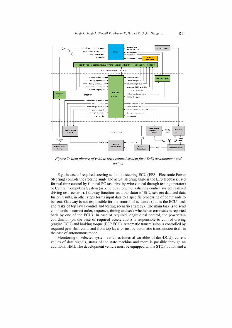
To embrace the obstacle on the right, see figure 6, first the right front wheel is braked, then the left wheel to curve around the obstacle. The right wheel is braked again to level the direction after passing the obstacle. After leveling and driving straight ahead, the vehicle is stopped by braking both front wheels, see figure 7.
Figure 7 presents the required and actual brake pressure curves on the individual wheels of the front axle. It is clear from the waveforms that first the pressure on the right wheel is required and realized, then on the left wheel, then on the right wheel, and
y
x
z (yaw rate)
road obstacle
Democar II
Figure 5: Experimental vehicles; left - Democar II 4WD (drive/steer/brake-by-wire) with own universal platform and Skoda Superb III (originally MQB
platform) with gateway system implementation (dev-DCU) for ADAS development
824
Stolfa S., Stolfa J., Simonik P., Mrovec T., Harach T.: Safety Design ...
finally both wheels are braked at the same time. The required brake pressure values are entered by the vehicle operator via wireless remote control. For this reason, the change in amplitude and the different length of the brake pressure requirements of the individual wheels can be seen. The actual pressure value is modulated in the form of PMW control voltages on the individual proportional valves of the ESP development module.
Figure 7: Characteristic Brake Curves when Steering around the Obstacle
Figure 8 presents the change in speed of the individual wheels of the front and rear axles. The vehicle reached a speed of 18 km / h during the test. For better maneuverability and function of the new tested assistance system, a higher vehicle speed and thus the kinetic energy of the vehicle is suitable. However, within the university testing and for safety reasons, the tests were performed up to a speed of 20 km / h. For this reason, a permanent drive torque was activated on the rear axle during the test during the obstacle avoidance maneuver, which emulated the vehicle's higher kinetic energy. When driving the vehicle after the maneuver, the driving torque was reduced to negative value for higher braking efficiency and then was set to zero value.

825
Stolfa S., Stolfa J., Simonik P., Mrovec T., Harach T.: Safety Design ...
Figure 8: Characteristic Wheel Velocity Curves when Steering around the Obstacle
Figure 9 presents the course of the actual values of the transverse (y-axis) and longitudinal (x-axis) acceleration of the vehicle. The figure shows the course of the yaw rate (in the z axis). The polarity of the waveforms corresponds to the polarity determined by the arrows of the coordinate system according to figure 6. Finally, this figure shows the total driving torque of the rear axle, which is positive from the beginning of the journey and negative only at the moment of the request to stop the vehicle and then zero when the vehicle is stationary. All presented acceleration, turning speed and total torque curves correspond to the performed test maneuver.
Figure 9: Characteristic Curve and Yaw Rate when Steering around the Obstacle
So far, the performed tests preliminary confirms the possibility that the proposed decomposition solution as depicted in 4.1 might work. Moreover, in case of the Democar embrace obstacle experiment, testing showed that it is possible even more

826
Stolfa S., Stolfa J., Simonik P., Mrovec T., Harach T.: Safety Design ...
than to maintain the desired path up to 4 seconds. Democar is able to perform the whole embrace maneuver around the obstacle without the functional steering (EPS) system.
Although the preliminary results are promising, we need to perform many more experiments to be able to prove the whole concept. For example, to list a few, we need to test the accuracy of the steering for different speeds, test the maneuver on low friction surface, test the maximum possible steering power resistance, test the steering possibility on real car.
5 Outlook and Summary
The research work presented in this article shows that by decomposition of ECUs (Electronic Control Units) at vehicle level it is possible to achieve a situation where in complex situations (e.g., lateral control such as steering) it is possible to use an older platform like MQB and decompose the steering case between the ESP (Electronic Stability Program) and the Steering Control Unit EPS (Electric Power Steering). The steering function by the ESP would take over the steering from the EPS until the driver takes over. In our experiment the system steered in a stable manner for longer than 6 seconds which is the time limit described in the UNECE guidelines for a HAD 3 level vehicle [UNECE 2020].
Why is this result important? In modern high-priced cars, each ECU is developed fault-operational which leads to very expensive solutions (e.g., four times faults considered per ECU) while the decomposition in the demo car combined two ASIL D ECUs which are complementary, ESP and EPS, and are already resent in the platform. This approach would allow e.g., to refine the existing MQB platform from Volkswagen to be able to fulfill HAD 2/3 fail-safe and fail-operational requirements in a cost-effective way. More experiments using the classical MQB platform and following the vehicle decomposition approach described in the paper are currently being planned and performed.
Acknowledgements
We are grateful to the contributions from the guest editor Dr Richard Messnarz from ISCN GesmbH, who is moderator of the cybersecurity task force in the German and Austrian working group SOQRATES (soqrates.eurospi.net) and contributed state of the art experiences in the field.
We are grateful to the European Commission which has funded the BLUEPRINT project DRIVES (2018 – 2021) [DRIVES 2021] [Stolfa 2020],[Stolfa 2020 2]. In this case the publications reflect the views only of the author(s), and the Commission cannot be held responsible for any use, which may be made of the information contained therein.
We are grateful to the EuroSPI community and conference series (www.eurospi.net) in which experts share experiences since 1994 and cybersecurity and JUCS has been promoted and experts from that community submitted papers to this journal.
We are grateful to the EU Project ECQA Certified Cybersecurity Engineer and Manager – Automotive Sector, Erasmus+ Programme, Grant Agreement No. 2020-1-CZ01-KA203-078494.

827
Stolfa S., Stolfa J., Simonik P., Mrovec T., Harach T.: Safety Design ...
This work has been financially supported by the European Regional Development Fund in “A Research Platform focused on Industry 4.0 and Robotics in Ostrava Agglomeration” project, reg. nr. CZ.02.1.01/0.0/0.0/17_049/0008425 within the Operational Programme Research, Development and Education and by the Ministry of Education of the Czech Republic and by grants of SGS No. SP2020/62 and SP2021/49 VŠB - Technical University of Ostrava, Czech Republic.
References
[Armengaud et al. 2019] Armengaud, E.; Frager, S.; Jones, S.; Massoner, A.; Parrilla, A. F.; Wikström, N. & Macher, G., Development Framework for Longitudinal Automated Driving Functions with Off-board Information Integration arXiv preprint arXiv:1906.10009, 2019
[Ekert et al. 2020] Ekert D., Messnarz R., Norimatsu S., Zehetner T., Aschbacher L. (2020) Experience with the Performance of Online Distributed Assessments – Using Advanced Infrastructure. In: Yilmaz M., Niemann J., Clarke P., Messnarz R. (eds) Systems, Software and Services Process Improvement. EuroSPI 2020. Communications in Computer and Information Science, vol 1251. Springer, Cham. https://doi.org/10.1007/978-3-030-56441-4_47
[Endsley et al. 1999] Endsley and Kaber, Level Of Automation Effects on Performance, Situation Awareness and Workload in a Dynamic Control Tas k., Ergonomics 42, number 3, 1999.72
[Höhn et al. 2016] Holger Höhn, Bernhard Sechser, Klaudia Dussa-Zieger, Richard Messnarz, Bernd Hindel, Software Engineering nach Automotive SPICE: Entwicklungsprozesse in der Praxis-Ein Continental-Projekt auf dem Weg zu Level 3, Kapitel: Systemdesign, dpunkt. Verlag, 2015
[ISO 26262 2011] ISO - International Organization for Standardization. “ISO 26262 Road vehicles Functional Safety Part 1-10”, 2011.
[ISO 26262 2018] ISO – International Organization for Standardization. “ISO CD 26262-2018 2nd Edition Road vehicles Functional Safety”, to appear.
[ISO 21434 2020] ISO/SAE 21434, Road vehicles – Cybersecurity engineering, ISO and SAE, Committee Draft (CD), 2018
[Ito 2020] Ito M. (2020) Supporting Process Design in the Autonomous Era with New Standards and Guidelines. In: Yilmaz M., Niemann J., Clarke P., Messnarz R. (eds) Systems, Software and Services Process Improvement. EuroSPI 2020. Communications in Computer and Information Science, vol 1251. Springer, Cham. https://doi.org/10.1007/978-3-030-56441-4_39
[KGAS 2018] KGAS, Konzerngrundanforderungen Software, Version 3.2, Volkswagen LAH 893.909: KGAS_3602, KGAS_3665, KGAS_3153, KGAS_3157, November 2018
[Kreiner et al. 2013] Kreiner, C. J.; Messnarz, R.; Riel, A.; Ekert, D.; Langgner, M.; Dick, T.; Reiner, M.: Automotive Knowledge Alliance AQUA - Integrating Automotive SPICE, Six Sigma, and Functional Safety. - in: Systems, Software and Services Process Improvement 20th European Conference, EuroSPI 2013, Dundalk, Ireland, June 25-27, 2013. Proceedings (2013), S. 333 – 344
[Kreiner et al. 2014] Kreiner, C. J.; Messnarz, R.; Riel, A.; Tichkiewitch, S.; Ekert, D.; Langgner, M.; Dick, T.: Integrating Functional Safety, Automotive SPICE and Six Sigma – The AQUA Knowledge Base and Integration Examples. - in: Systems, Software and Services Process Improvement 21st European Conference, EuroSPI 2014 (2014), S. 285 – 295

828
Stolfa S., Stolfa J., Simonik P., Mrovec T., Harach T.: Safety Design ...
[Kreiner et al. 2015] Kreiner Christian, Messnarz, R., Riel A., et. al, The AQUA Automotive Sector Skills Alliance: Best Practice in an Integrated Engineering Approach, Software Quality Professional. Jun2015, Vol. 17 Issue 3, p35-45. 11p., 2015
[Macher et al. 2017] G. Macher, R. Messnarz, C. Kreiner, et. al, Integrated Safety and Security Development in the Automotive Domain, Working Group 17AE-0252/2017-01-1661, SAE International, June 2017
[Macher et al. 2017 b] Macher G., Much A., Riel A., Messnarz R., Kreiner C. (2017) Automotive SPICE, Safety and Cybersecurity Integration. In: Tonetta S., Schoitsch E., Bitsch F. (eds) Computer Safety, Reliability, and Security. SAFECOMP 2017. Lecture Notes in Computer Science, vol 10489. Springer, Cham
[Messnarz et al. 2009] Richard Messnarz, Hans‐Leo Ross, Stephan Habel, Frank König, Abdelhadi Koundoussi, Jürgen Unterrreitmayer, Damjan Ekert, Integrated Automotive SPICE and safety assessments, Volume14, Issue5, Special Issue: Part 1: Special Issue on SPI Experiences and Innovation for Global Software Development, WILEY, September/October 2009, Pages 279-288, https://doi.org/10.1002/spip.429
[Messnarz et al. 2016] Messnarz, R.; Kreiner, C. & Riel, A. “Integrating Automotive SPICE, Functional Safety, and Cybersecurity Concepts: A Cybersecurity Layer Model”, Software Quality Professional, 2016.
[Messnarz et al. 2017] Messnarz R., Sehr M., Wüstemann I., Humpohl J., Ekert D. (2017) Experiences with SQIL – SW Quality Improvement Leadership Approach from Volkswagen. In: Stolfa J., Stolfa S., O'Connor R., Messnarz R. (eds) Systems, Software and Services Process Improvement. EuroSPI 2017. Communications in Computer and Information Science, vol 748. Springer, Cham
[Messnarz 2017 b] Messnarz R., Much A., Kreiner C., Biro M., Gorner J. (2017) Need for the Continuous Evolution of Systems Engineering Practices for Modern Vehicle Engineering. In: Stolfa J., Stolfa S., O'Connor R., Messnarz R. (eds) Systems, Software and Services Process Improvement. EuroSPI 2017. Communications in Computer and Information Science, vol 748. Springer, Cham. https://doi.org/10.1007/978-3-319-64218-5_36
[Messnarz et al. 2019] Messnarz R., Macher G., Stolfa J., Stolfa S. (2019) Highly Autonomous Vehicle (System) Design Patterns – Achieving Fail Operational and High Level of Safety and Security. In: Walker A., O'Connor R., Messnarz R. (eds) Systems, Software and Services Process Improvement. EuroSPI 2019. Communications in Computer and Information Science, vol 1060. Springer, Cham. https://doi.org/10.1007/978-3-030-28005-5_36
[Messnarz et al. 2019 b] Messnarz R., Ekert D., Zehetner T., Aschbacher L. (2019) Experiences with ASPICE 3.1 and the VDA Automotive SPICE Guidelines – Using Advanced Assessment Systems. In: Walker A., O'Connor R., Messnarz R. (eds) Systems, Software and Services Process Improvement. EuroSPI 2019. Communications in Computer and Information Science, vol 1060. Springer, Cham
[Messnarz et al. 2020] Messnarz R. et al. (2020) Automotive Cybersecurity Engineering Job Roles and Best Practices – Developed for the EU Blueprint Project DRIVES. In: Yilmaz M., Niemann J., Clarke P., Messnarz R. (eds) Systems, Software and Services Process Improvement. EuroSPI 2020. Communications in Computer and Information Science, vol 1251. Springer, Cham. https://doi.org/10.1007/978-3-030-56441-4_37
[Riel et al. 2018] Andreas Riel, Christian Kreiner, Richard Messnarz, Alexander Much, An architectural approach to the integration of safety and security requirements in smart products and systems design, CIRP Annals, Volume 67, Issue 1, 2018, Pages 173-176, ISSN 0007-8506, https://doi.org/10.1016/j.cirp.2018.04.022.
829
Stolfa S., Stolfa J., Simonik P., Mrovec T., Harach T.: Safety Design ...
[SAE 2016] SAE J3061, Cybersecurity Guidebook for Cyber-Physical Vehicle Systems, SAE - Society of Automotive Engineers, USA, Jan. 2016
[Steger 2020] Steger B., Ekert D., Messnarz R., Stolfa J., Stolfa S., Velart Z. (2020) Metrics and Dashboard for Level 2 – Experience. In: Yilmaz M., Niemann J., Clarke P., Messnarz R. (eds) Systems, Software and Services Process Improvement. EuroSPI 2020. Communications in Computer and Information Science, vol 1251. Springer, Cham. https://doi.org/10.1007/978-3-030-56441-4_49
[Stolfa et al. 2020] Jakub Stolfa, Svatopluk Stolfa, Richard Messnarz, Omar Veledar, Damjan Ekert, Georg Macher, Utimia Madaleno (2020) Automotive Engineering Skills and Job Roles of the Future?. In: Yilmaz M., Niemann J., Clarke P., Messnarz R. (eds) Systems, Software and Services Process Improvement. EuroSPI 2020. Communications in Computer and Information Science, vol 1251. Springer, Cham. https://doi.org/10.1007/978-3-030-56441-4_26
[Stolfa et al. 2020 b] Jakub Stolfa, Svatopluk Stolfa, Christian Baio, Utimia Madaleno, Petr Dolejsi, Federico Brugnoli, Richard Messnarz, DRIVES—EU blueprint project for the automotive sector—A literature review of drivers of change in automotive industry, in: Journal of Software: Evolution and Process, Volume32, Issue3, Special Issue: Addressing Evolving Requirements Faced by the Software Industry, March 2020
[Vlakveld et al. 2015] Vlakveld et al., An Empirical Exploration of the Impact of Transition of Control on Situation Awareness for Potential Hazards;An Experiment about the Hazard Perception Capabilities of Drivers after Interruption in a Video-based Scanning Task. The Hague: SWOV, 2015.71
[UNECE 2020] Dutch Safety Board, Who is in control? - Road safety and automation in road traffic https://unece.org/DAM/trans/doc/2020/wp29grva/GRVA-05-48e.pdf, last visited 11.4.2021
[UNECE 2020 b] UNECE, World Forum for Harmonization of Vehicle Regulations, Report of the Working Party on Automated/Autonomous and Connected Vehicles, Regulation ECE/TRANS/WP.29/GRVA/5, 2020
[Wright et al. 2016] Wright et al., Experienced Drivers are Quicker to Achieve Situation Awareness than Inexperienced Drivers in Situations of Transfer of Control within Level 3 Autonomous Environment, in Proceedings of the Human Factor and Ergonomics Society 2016 Annual Meeting, vol. 60, 2016.73
[Zhang et al. 2019] Zhang et al., Determinants of Take-Over Time from Automated Driving: A Meta-Analysis Of 129 Studies, Transportation Research Part F: Traffic Psychology and Behaviour 64 2019
[Ozana et al. 2019] S. Ozana, M. Pies, R. Hajovsky, J. Koziorek, and O. Horacek, "Application of PIL approach for automated transportation center," in Lecture Notes in Computer Science (including subseries Lecture Notes in Artificial Intelligence and Lecture Notes in Bioinformatics) vol. 8838, ed, 2014, pp. 501-513