Embed Size (px)
Citation preview
Safety Critical Systems Design:
Patterns and Practices for Designing Mission and Safety-
Critical Systems*
* Portions adopted from the author’s book Doing Hard Time: Developing Real-Time Systems with UML, Objects, Frameworks, and Patterns, Addison-Wesley Publishing, 1999.
Bruce Powel Douglass, [email protected]
Chief Evangelist, I-Logix
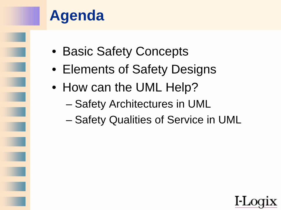
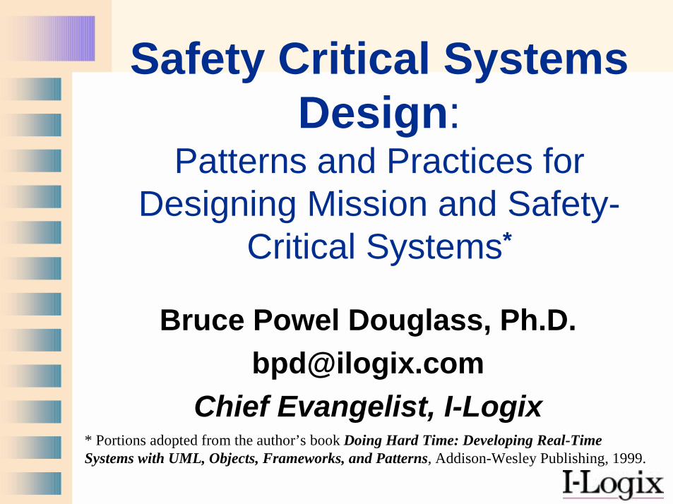
Agenda
• Basic Safety Concepts• Elements of Safety Designs• How can the UML Help?
– Safety Architectures in UML– Safety Qualities of Service in UML
Why Care About Safety?
• Safety is not discussed in the literature
• Safety is not taught in the colleges• Yet without training or guidance,
Embedded systems are assuming more safety roles every day.
What is Safety?
• Safety is freedom from accidents or losses.• Safety is not reliability!
– Reliability is the probability that a system will perform its intended function satisfactorily.
• Safety is not security!– Security is protection or defense against
attack, interference, or espionage.
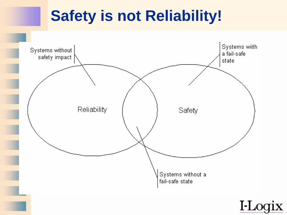
Safety is not Reliability!
Safety-Related Concepts
• Accident is a loss of some kind, such as injury, death, or equipment damage
• Risk is a combination of the likelihood of an accident and its severity:
risk = p(a) * s(a)• Hazard is a set of conditions and/or
events that leads to an accident.
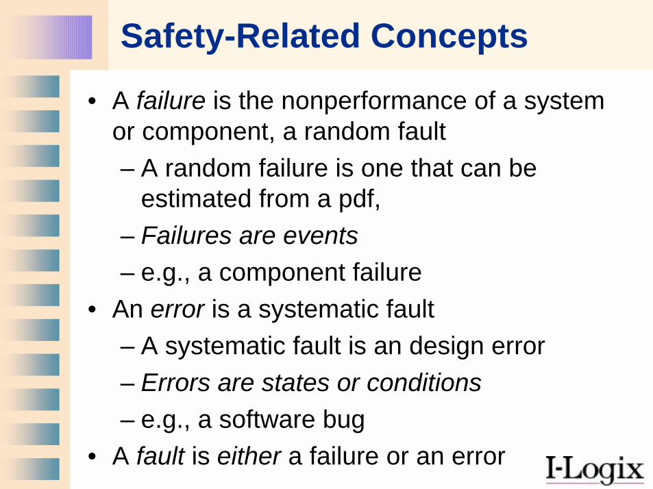
Safety-Related Concepts• A failure is the nonperformance of a system
or component, a random fault– A random failure is one that can be
estimated from a pdf, – Failures are events– e.g., a component failure
• An error is a systematic fault – A systematic fault is an design error– Errors are states or conditions– e.g., a software bug
• A fault is either a failure or an error
Safety-Related Concepts
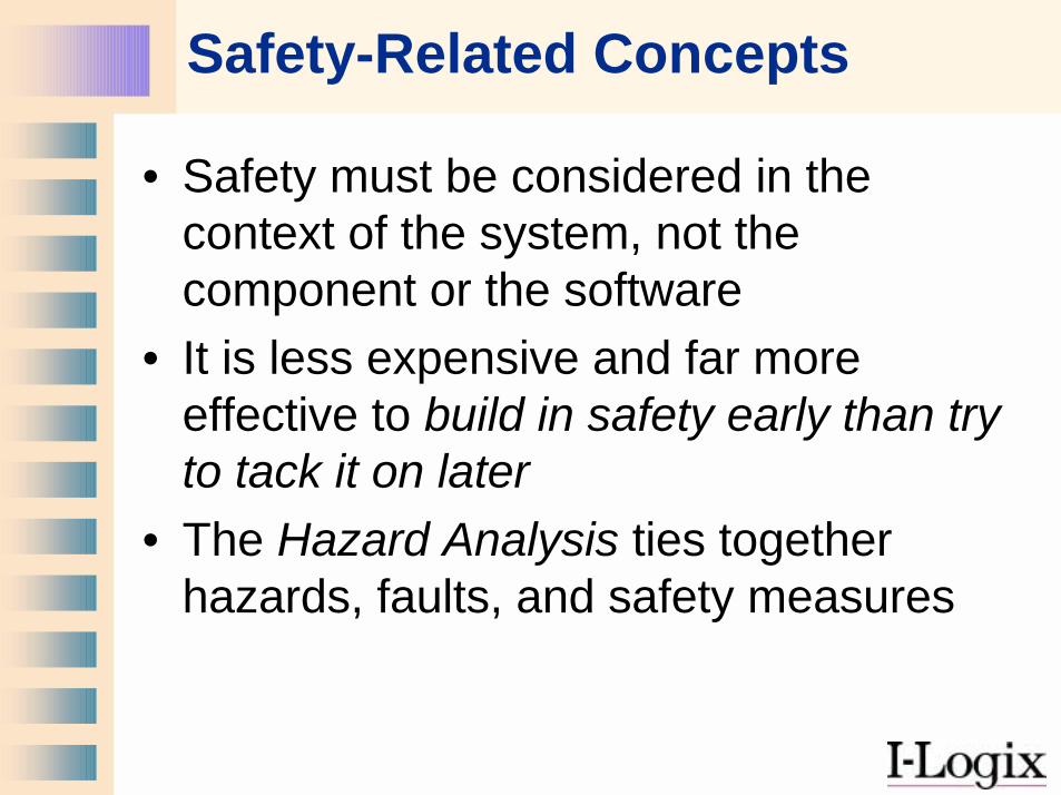
• Safety must be considered in the context of the system, not the component or the software
• It is less expensive and far more effective to build in safety early than try to tack it on later
• The Hazard Analysis ties together hazards, faults, and safety measures
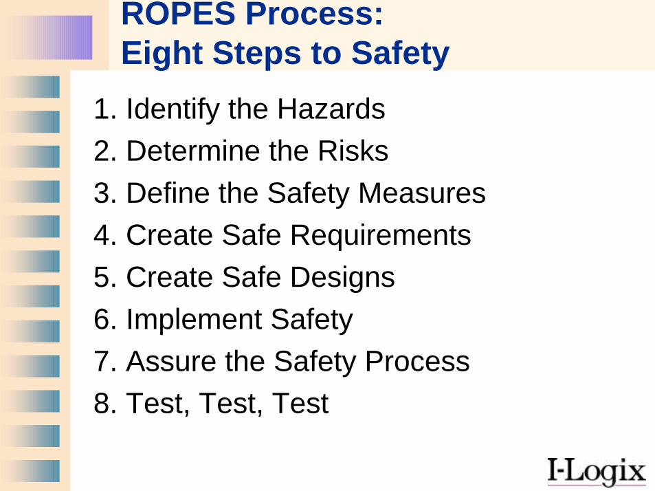
ROPES Process:Eight Steps to Safety
1. Identify the Hazards2. Determine the Risks3. Define the Safety Measures4. Create Safe Requirements5. Create Safe Designs6. Implement Safety7. Assure the Safety Process8. Test, Test, Test
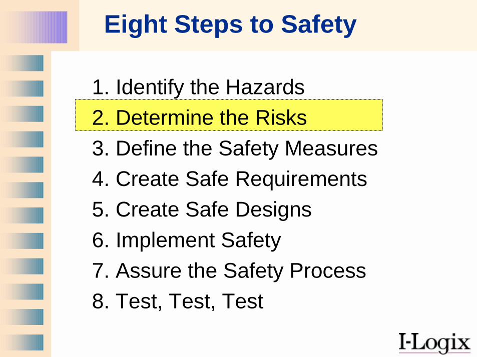
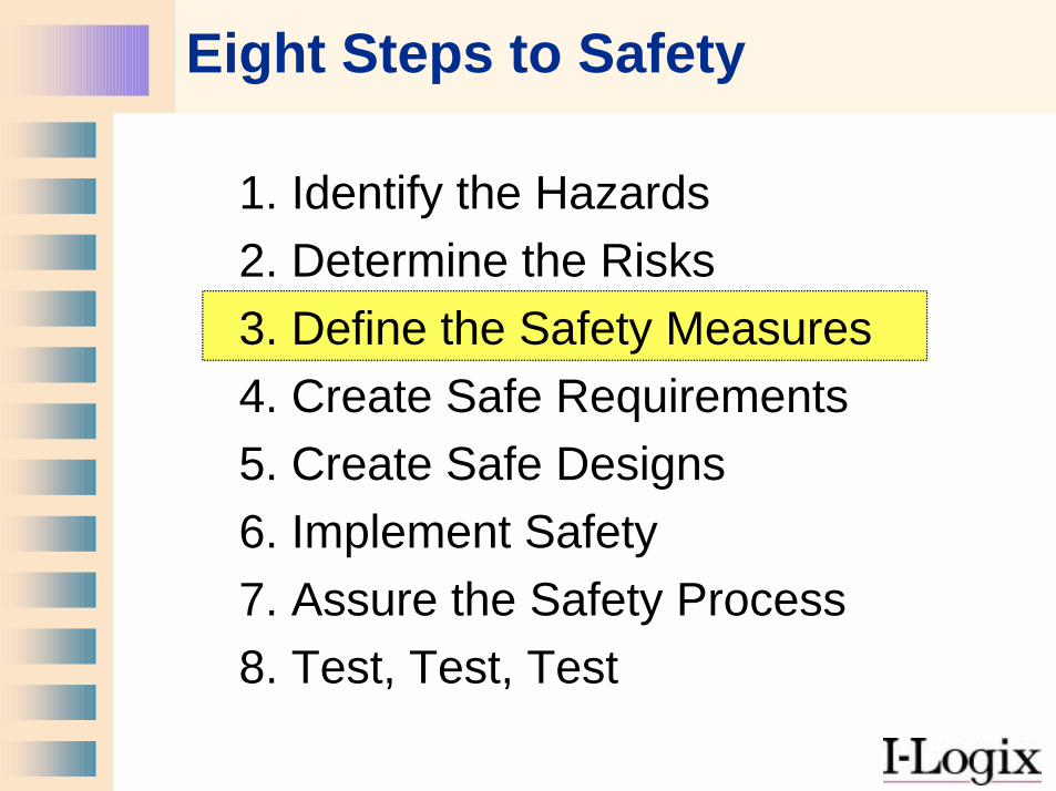
Eight Steps to Safety
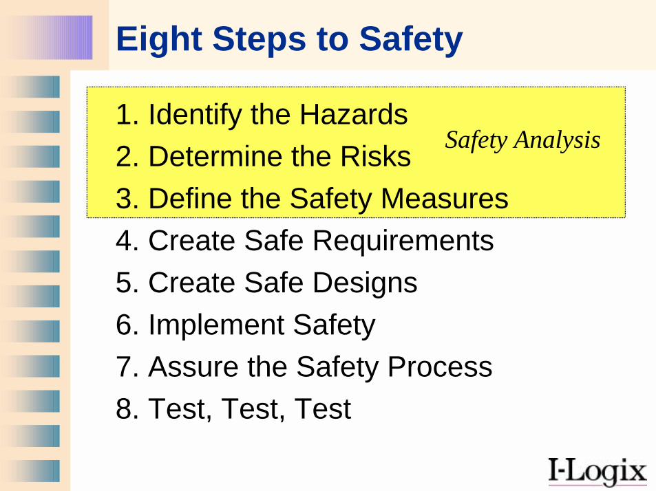
1. Identify the Hazards2. Determine the Risks3. Define the Safety Measures4. Create Safe Requirements5. Create Safe Designs6. Implement Safety7. Assure the Safety Process8. Test, Test, Test
Safety Analysis
Safety Analysis
• You must identify the hazards of the system
• You must identify faults that can lead to hazards
• You must define safety control measures to handle hazards
• These culminate in the Hazard Analysis• The Hazard Analysis feeds into the
Requirements Specification
Eight Steps to Safety
1. Identify the Hazards2. Determine the Risks3. Define the Safety Measures4. Create Safe Requirements5. Create Safe Designs6. Implement Safety7. Assure the Safety Process8. Test, Test, Test
Hazard Causes
• Release of Energy• Release of Toxins• Interference with life support or
other safety-related function• Misleading safety personnel• Failure to alarm
Types of Hazards
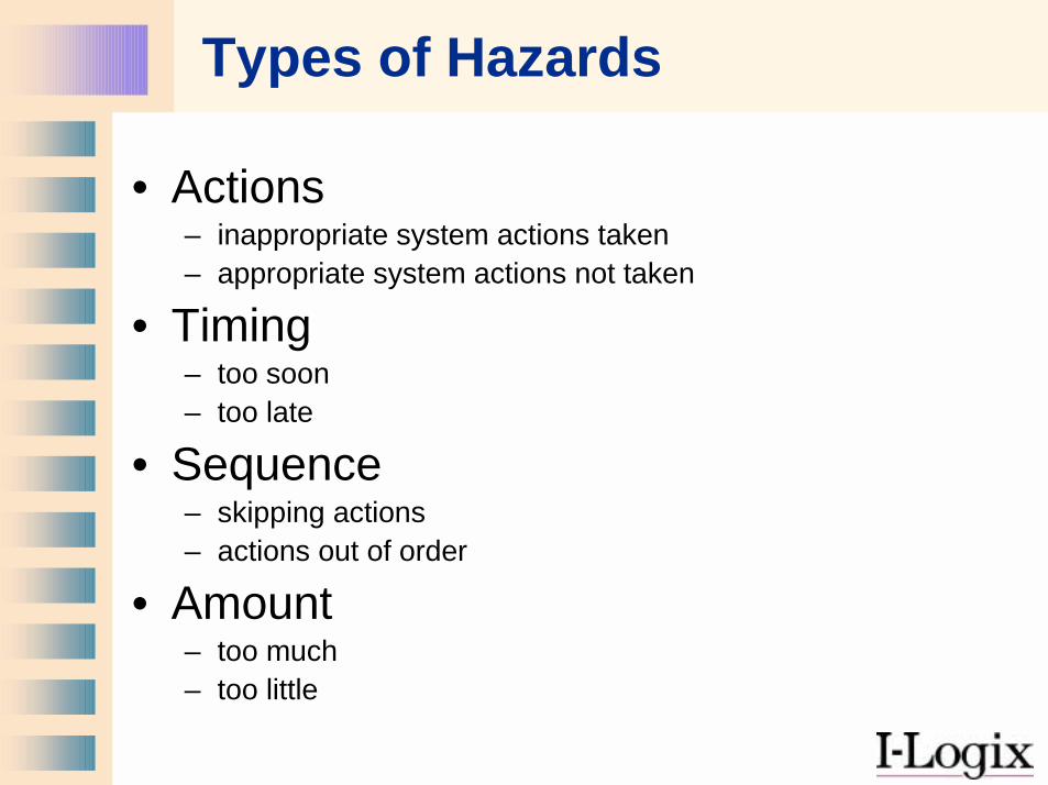
• Actions– inappropriate system actions taken– appropriate system actions not taken
• Timing– too soon– too late
• Sequence– skipping actions– actions out of order
• Amount– too much– too little
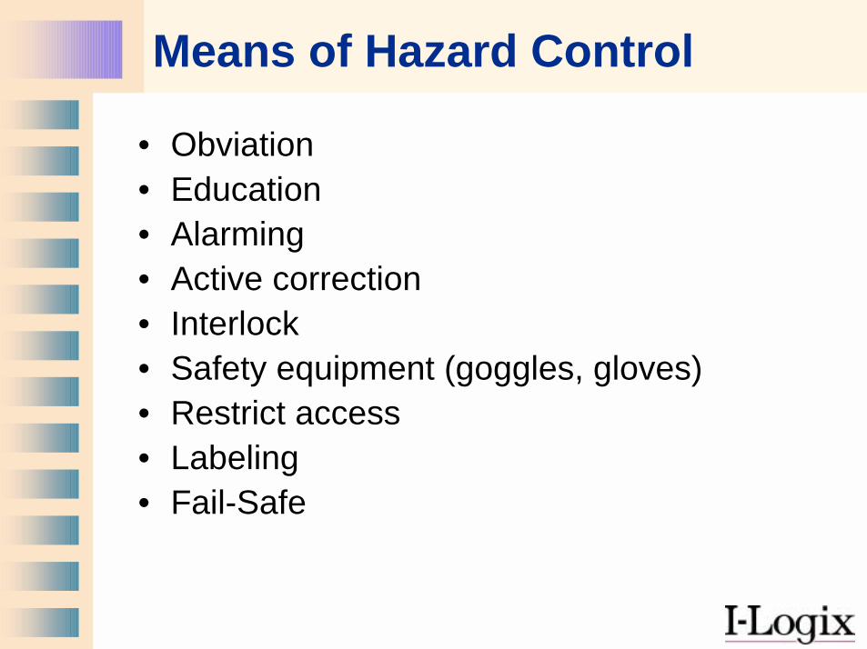
Means of Hazard Control
• Obviation• Education• Alarming• Active correction• Interlock• Safety equipment (goggles, gloves)• Restrict access• Labeling• Fail-Safe
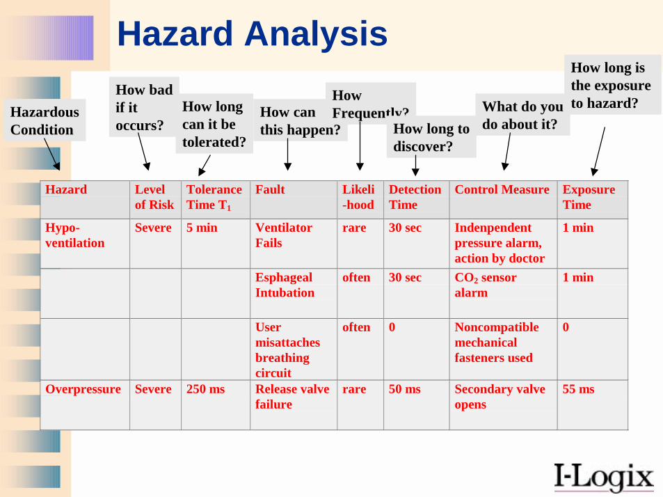
Hazard Analysis
Hazard Levelof Risk
ToleranceTime T1
Fault Likeli-hood
DetectionTime
Control Measure ExposureTime
Hypo-ventilation
Severe 5 min VentilatorFails
rare 30 sec Indenpendentpressure alarm,action by doctor
1 min
EsphagealIntubation
often 30 sec CO2 sensoralarm
1 min
Usermisattachesbreathingcircuit
often 0 Noncompatiblemechanicalfasteners used
0
Overpressure Severe 250 ms Release valvefailure
rare 50 ms Secondary valveopens
55 ms
HazardousCondition
How badif itoccurs?
How longcan it betolerated?
How canthis happen?
How Frequently?
How long todiscover?
What do youdo about it?
How long is the exposure to hazard?
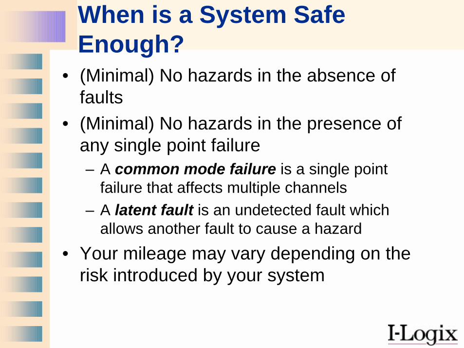
When is a System Safe Enough?
• (Minimal) No hazards in the absence of faults
• (Minimal) No hazards in the presence of any single point failure– A common mode failure is a single point
failure that affects multiple channels– A latent fault is an undetected fault which
allows another fault to cause a hazard• Your mileage may vary depending on the
risk introduced by your system
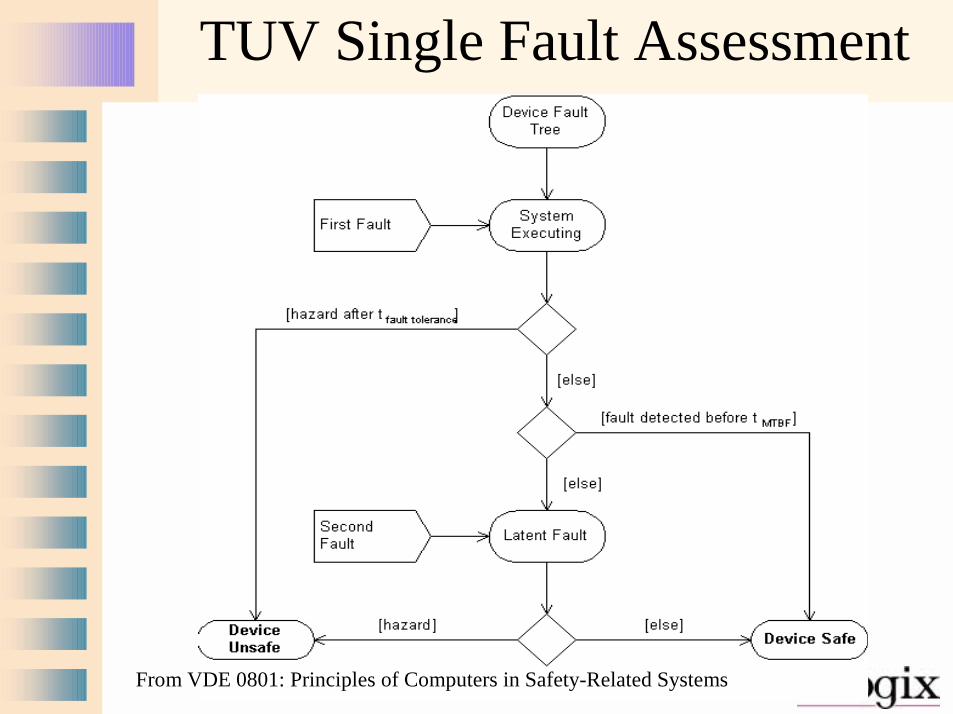
TUV Single Fault Assessment
From VDE 0801: Principles of Computers in Safety-Related Systems
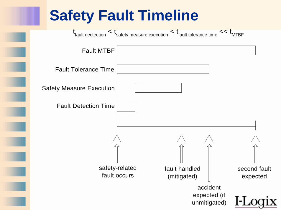
Safety Fault Timeline
Fault MTBF
Fault Tolerance Time
Safety Measure Execution
Fault Detection Time
safety-relatedfault occurs
tfault dectection < tsafety measure execution < tfault tolerance time << tMTBF
accidentexpected (ifunmitigated)
fault handled(mitigated)
second faultexpected
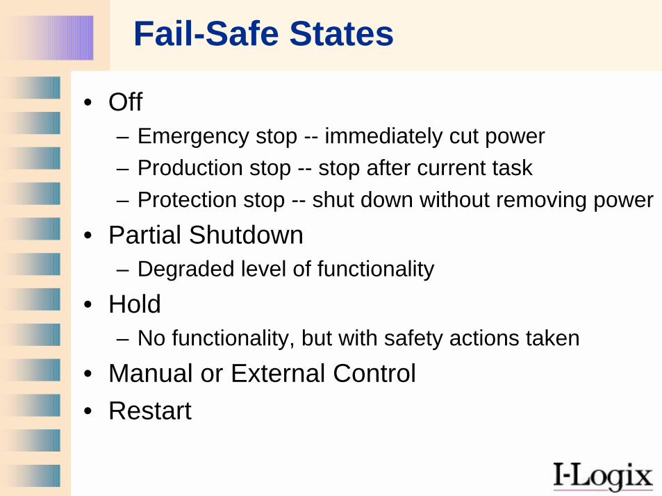
Fail-Safe States
• Off– Emergency stop -- immediately cut power– Production stop -- stop after current task– Protection stop -- shut down without removing power
• Partial Shutdown– Degraded level of functionality
• Hold– No functionality, but with safety actions taken
• Manual or External Control• Restart
Eight Steps to Safety
1. Identify the Hazards2. Determine the Risks3. Define the Safety Measures4. Create Safe Requirements5. Create Safe Designs6. Implement Safety7. Assure the Safety Process8. Test, Test, Test
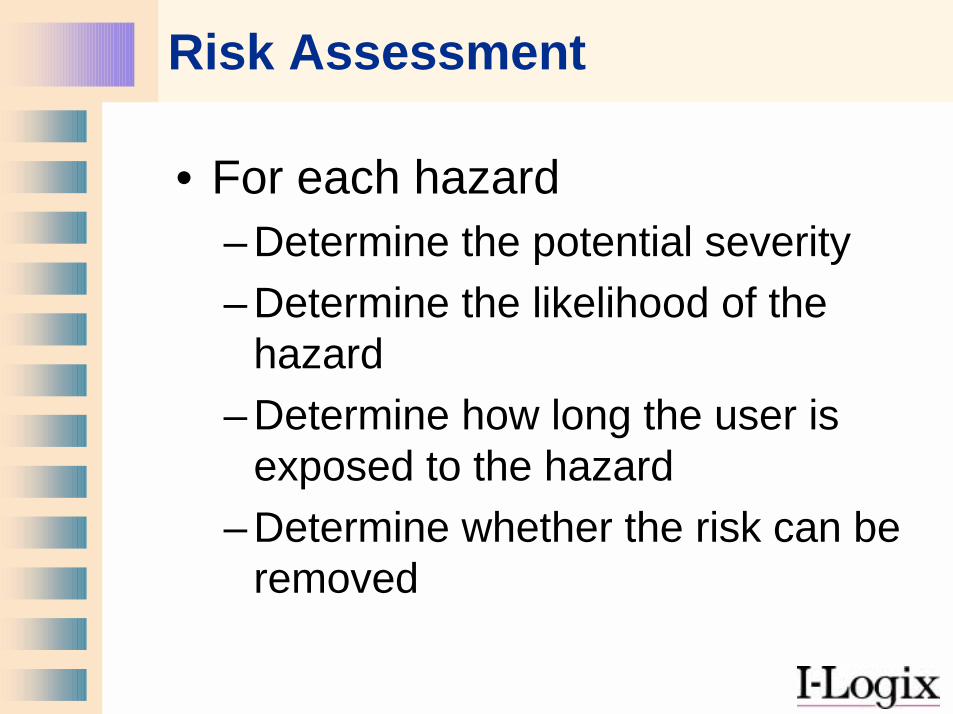
Risk Assessment
• For each hazard– Determine the potential severity– Determine the likelihood of the
hazard– Determine how long the user is
exposed to the hazard– Determine whether the risk can be
removed
1
8
7
6
5
4
3
2 1
7
6
5
4
3
2 1
-
6
5
4
3
2
- -W3 W2 W1S1
S2
S3
S4
E1
E2
E1
E2
G1
G2G1
G2
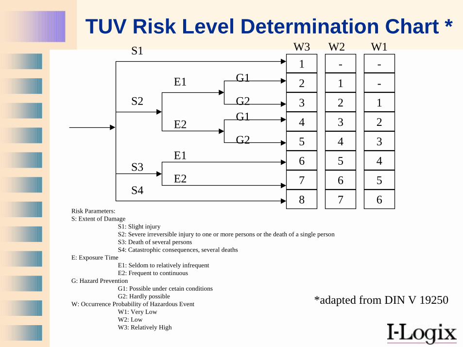
TUV Risk Level Determination Chart *
Risk Parameters:S: Extent of Damage
S1: Slight injuryS2: Severe irreversible injury to one or more persons or the death of a single personS3: Death of several personsS4: Catastrophic consequences, several deaths
E: Exposure TimeE1: Seldom to relatively infrequentE2: Frequent to continuous
G: Hazard PreventionG1: Possible under cetain conditionsG2: Hardly possible
W: Occurrence Probability of Hazardous EventW1: Very LowW2: LowW3: Relatively High
*adapted from DIN V 19250
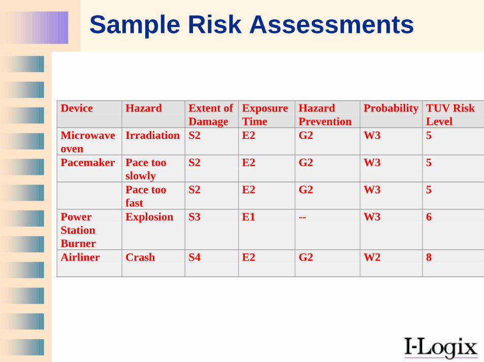
Sample Risk Assessments
Device Hazard Extent ofDamage
ExposureTime
HazardPrevention
Probability TUV RiskLevel
Microwaveoven
Irradiation S2 E2 G2 W3 5
Pacemaker Pace tooslowly
S2 E2 G2 W3 5
Pace toofast
S2 E2 G2 W3 5
PowerStationBurner
Explosion S3 E1 -- W3 6
Airliner Crash S4 E2 G2 W2 8
Eight Steps to Safety
1. Identify the Hazards2. Determine the Risks3. Define the Safety Measures4. Create Safe Requirements5. Create Safe Designs6. Implement Safety7. Assure the Safety Process8. Test, Test, Test
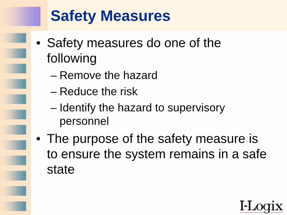
Safety Measures• Safety measures do one of the
following– Remove the hazard– Reduce the risk– Identify the hazard to supervisory
personnel• The purpose of the safety measure is
to ensure the system remains in a safe state
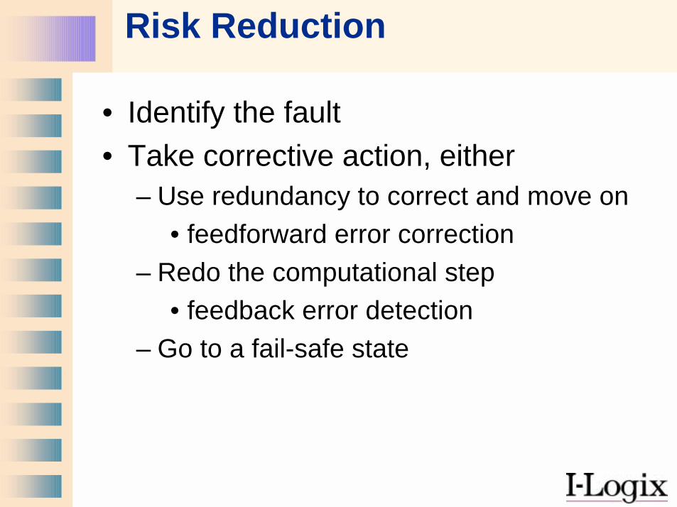
Risk Reduction
• Identify the fault• Take corrective action, either
– Use redundancy to correct and move on• feedforward error correction
– Redo the computational step• feedback error detection
– Go to a fail-safe state
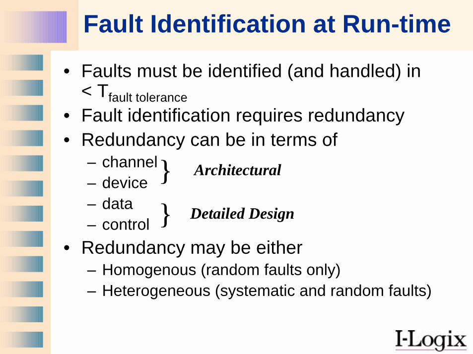
Fault Identification at Run-time
• Faults must be identified (and handled) in < Tfault tolerance
• Fault identification requires redundancy• Redundancy can be in terms of
– channel– device– data– control
• Redundancy may be either– Homogenous (random faults only)– Heterogeneous (systematic and random faults)
Architectural
Detailed Design
}}
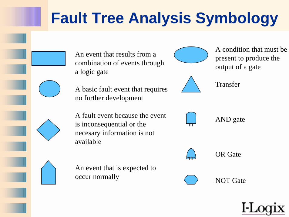
Fault Tree Analysis Symbology
An event that results from acombination of events througha logic gate
A basic fault event that requiresno further development
A fault event because the eventis inconsequential or thenecesary information is notavailable
An event that is expected tooccur normally
A condition that must bepresent to produce theoutput of a gate
Transfer
AND gate
OR Gate
NOT Gate
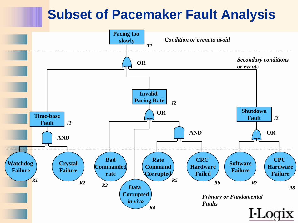
Subset of Pacemaker Fault Analysis
ShutdownFault
Invalid Pacing Rate
Time-baseFault
Pacing too slowly
OR
BadCommanded
rate
CrystalFailure
CRC Hardware
Failed
Watchdog Failure
RateCommandCorrupted
SoftwareFailure
CPU Hardware
Failure
Data Corrupted
in vivo
ANDOR
OR
AND
Condition or event to avoid
Secondary conditions or events
Primary or FundamentalFaults
T1
R1 R2 R3
R4
R5 R6 R7R8
I1
I2
I3
Eight Steps to Safety
1. Identify the Hazards2. Determine the Risks3. Define the Safety Measures4. Create Safe Requirements5. Create Safe Designs6. Implement Safety7. Assure the Safety Process8. Test, Test, Test
Safe Requirements
• Requirements specification follows initial hazard analysis
• Specific requirements should track back to hazard analysis
• Architectural framework should be selected with safety needs in mind
Eight Steps to Safety
1. Identify the Hazards2. Determine the Risks3. Define the Safety Measures4. Create Safe Requirements5. Create Safe Designs6. Implement Safety7. Assure the Safety Process8. Test, Test, Test
Isolate Safety Functions• Safety-relevant systems are 300-1000%
more effort to produce• Isolation of safety systems allows more
expedient development• Care must be taken that the safety
system is truly isolated so that a defect in the non-safety system cannot affect the safety system– Different processor– Different heavy-weight tasks (depends on
OS)
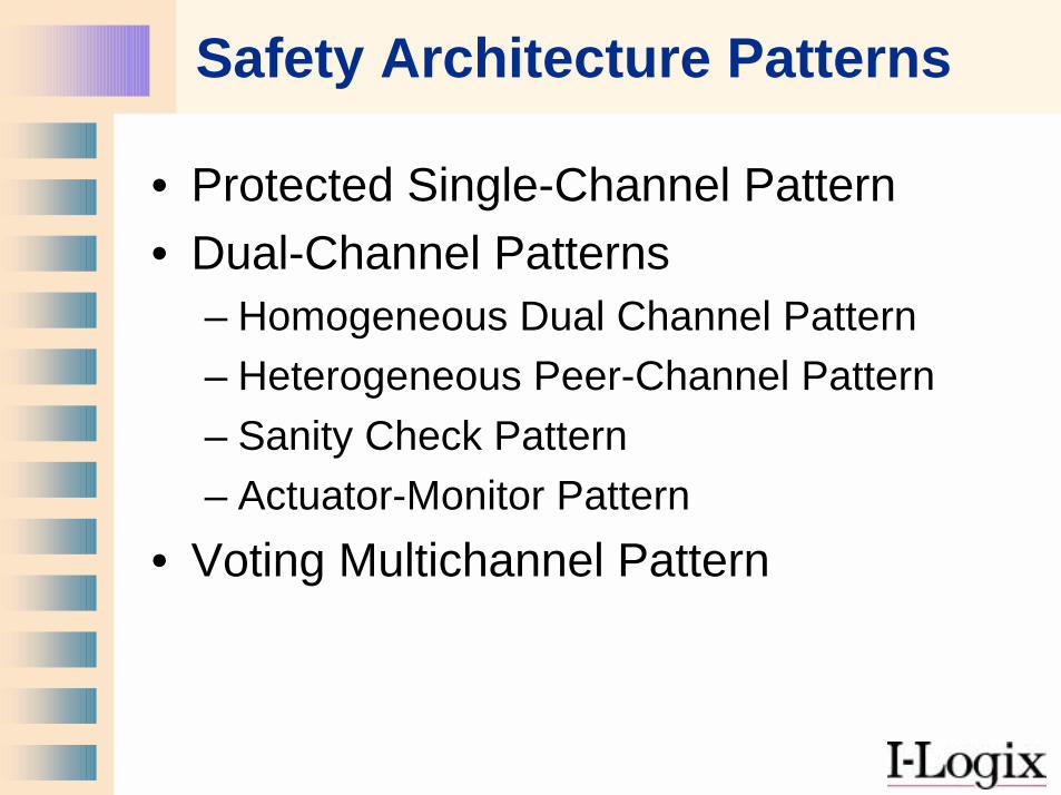
Safety Architecture Patterns
• Protected Single-Channel Pattern• Dual-Channel Patterns
– Homogeneous Dual Channel Pattern– Heterogeneous Peer-Channel Pattern– Sanity Check Pattern – Actuator-Monitor Pattern
• Voting Multichannel Pattern
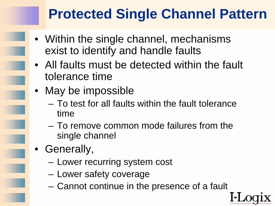
Protected Single Channel Pattern• Within the single channel, mechanisms
exist to identify and handle faults• All faults must be detected within the fault
tolerance time • May be impossible
– To test for all faults within the fault tolerance time
– To remove common mode failures from the single channel
• Generally, – Lower recurring system cost– Lower safety coverage– Cannot continue in the presence of a fault
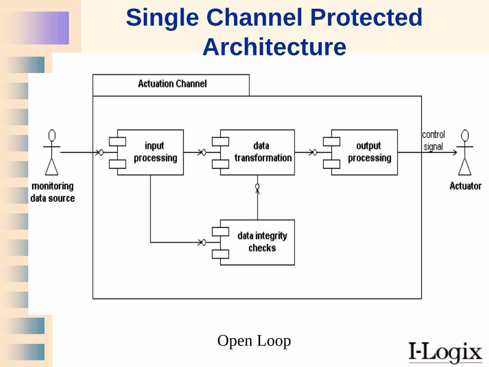
Single Channel Protected Architecture
Open Loop
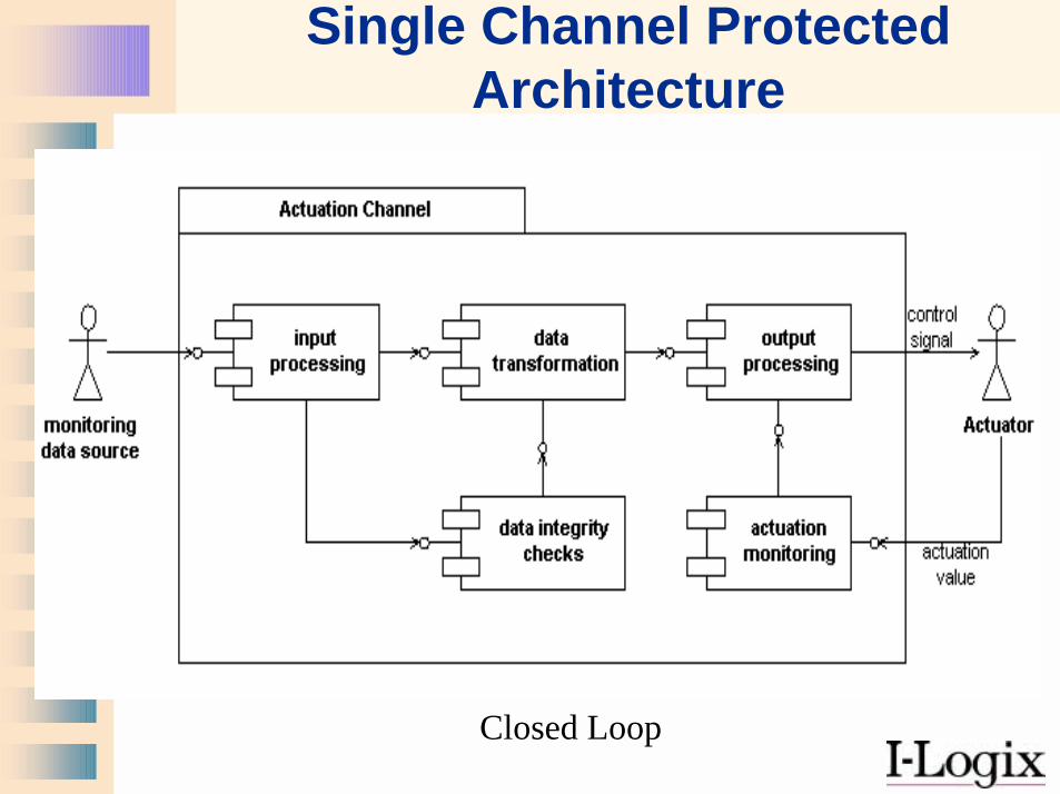
Single Channel Protected Architecture
Closed Loop
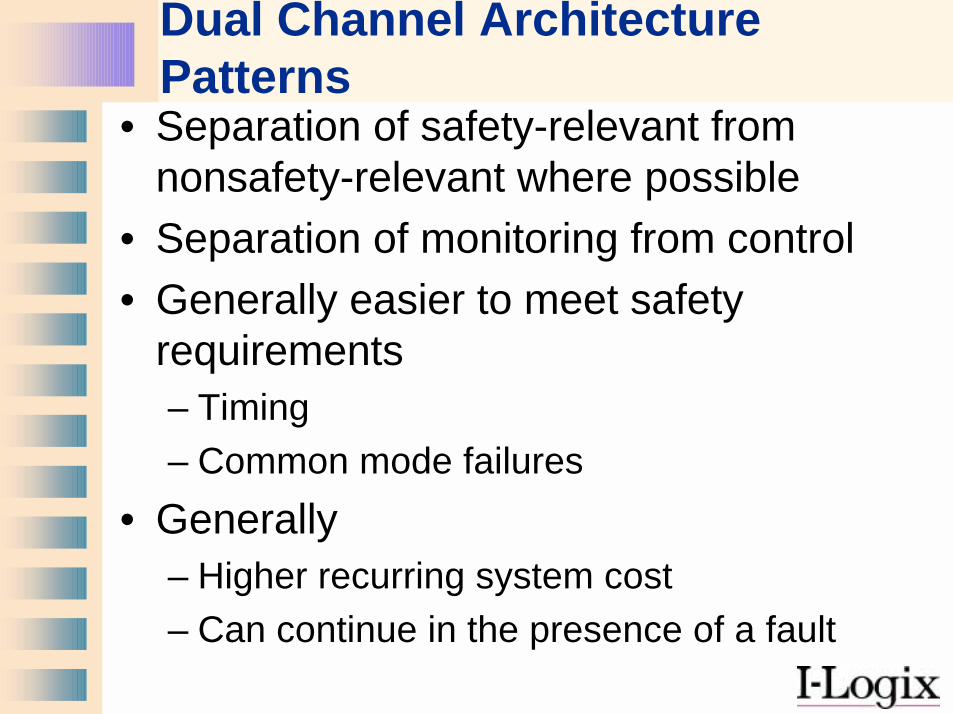
Dual Channel Architecture Patterns
• Separation of safety-relevant fromnonsafety-relevant where possible
• Separation of monitoring from control• Generally easier to meet safety
requirements– Timing– Common mode failures
• Generally – Higher recurring system cost– Can continue in the presence of a fault
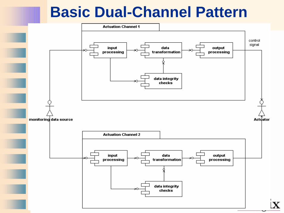
Basic Dual-Channel Pattern
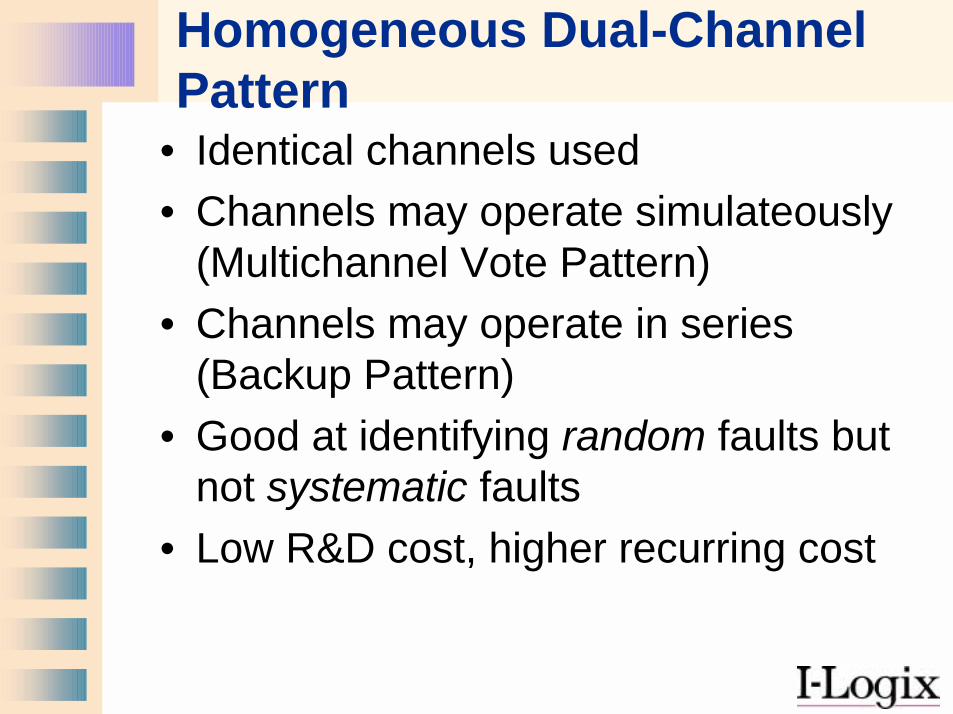
Homogeneous Dual-Channel Pattern
• Identical channels used• Channels may operate simulateously
(Multichannel Vote Pattern)• Channels may operate in series
(Backup Pattern)• Good at identifying random faults but
not systematic faults• Low R&D cost, higher recurring cost
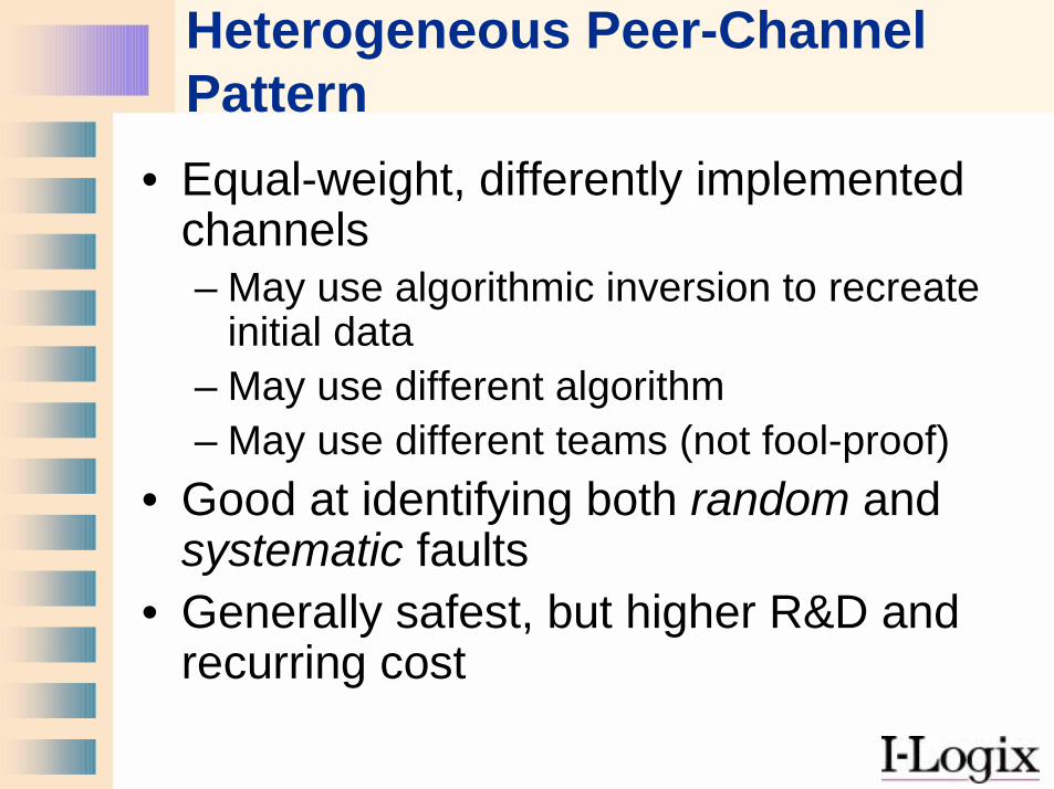
Heterogeneous Peer-Channel Pattern
• Equal-weight, differently implemented channels– May use algorithmic inversion to recreate
initial data– May use different algorithm– May use different teams (not fool-proof)
• Good at identifying both random and systematic faults
• Generally safest, but higher R&D and recurring cost
Sanity Check Pattern
• A primary actuator channel does real computations
• A light-weight secondary channel checks the reasonableness of the primary channel
• Good for detection of both random and systematic faults
• May not detect faults which result in small variance
• Relatively inexpensive to implement, lower coverage, cannot continue in the presence of fault
Monitor-Actuator Pattern
• Separates actuation from the monitoring of that actuation
• If the actuator channel fails, the monitor channel detects it
• If the monitor channel fails, the actuator channel continues correctly
• Requires fault isolation to be single-fault tolerant– Actuator channel cannot use the monitor
itself
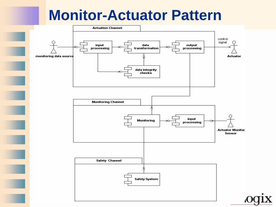
Monitor-Actuator Pattern
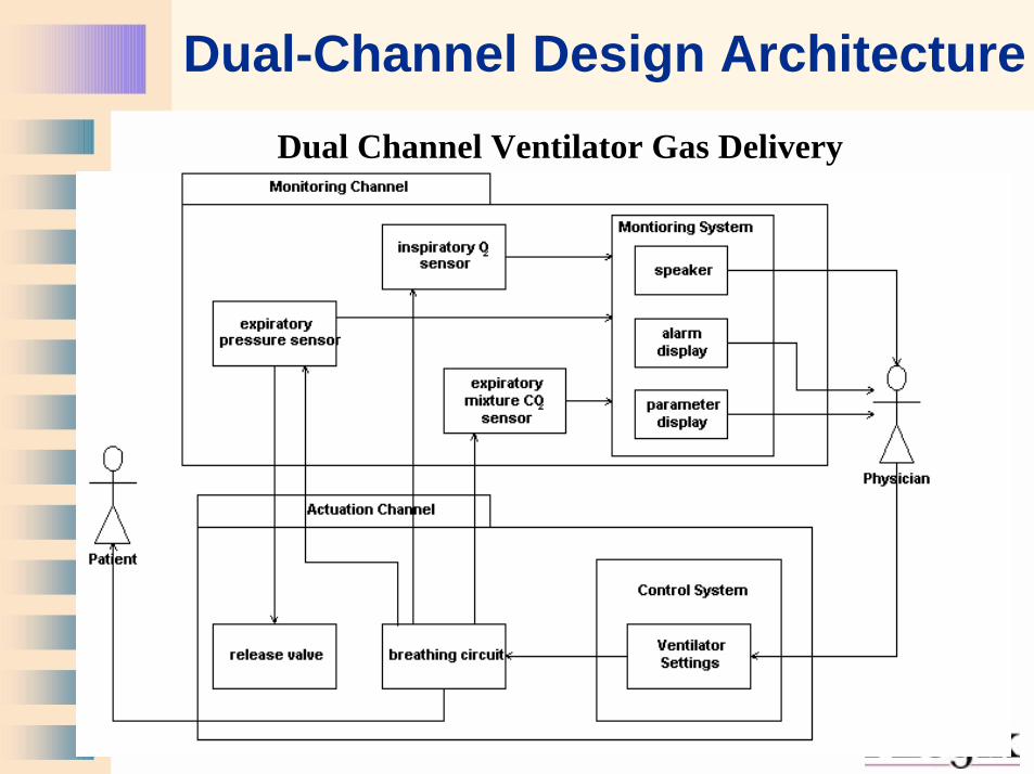
Dual-Channel Design ArchitectureDual Channel Ventilator Gas Delivery
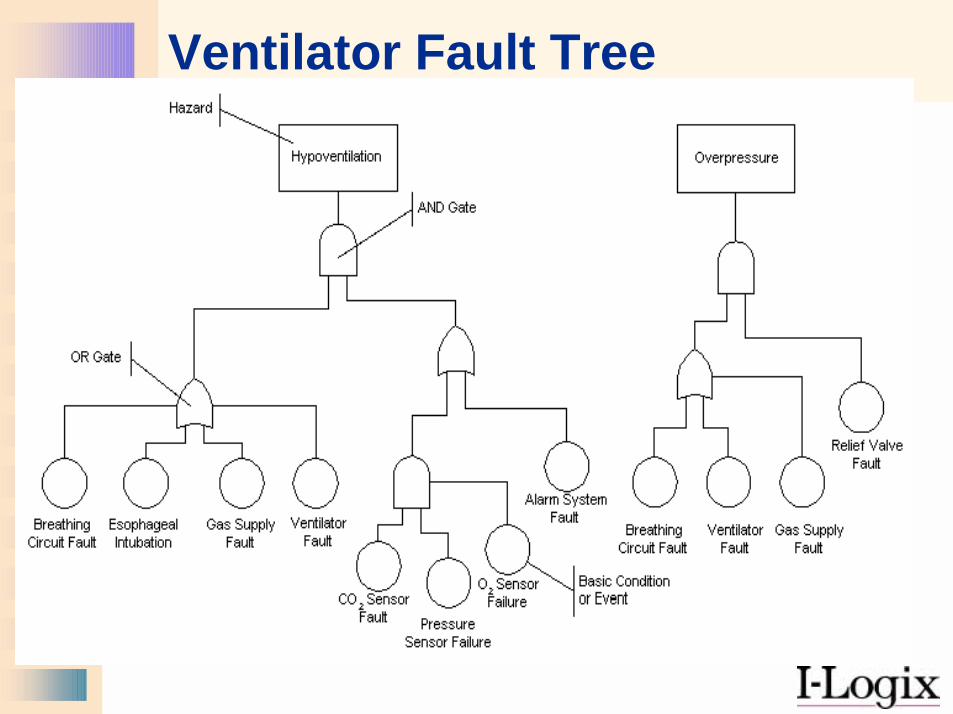
Ventilator Fault Tree
Multiple Channels with Voting
• Channels may be homogenous or heterogeneous
• Compare results of odd number of peer channels
• Primary channel with secondary reasonableness checks– May use algorithmic inversion to recreate
initial data– May use different algorithm– May use different teams (not fool-proof)
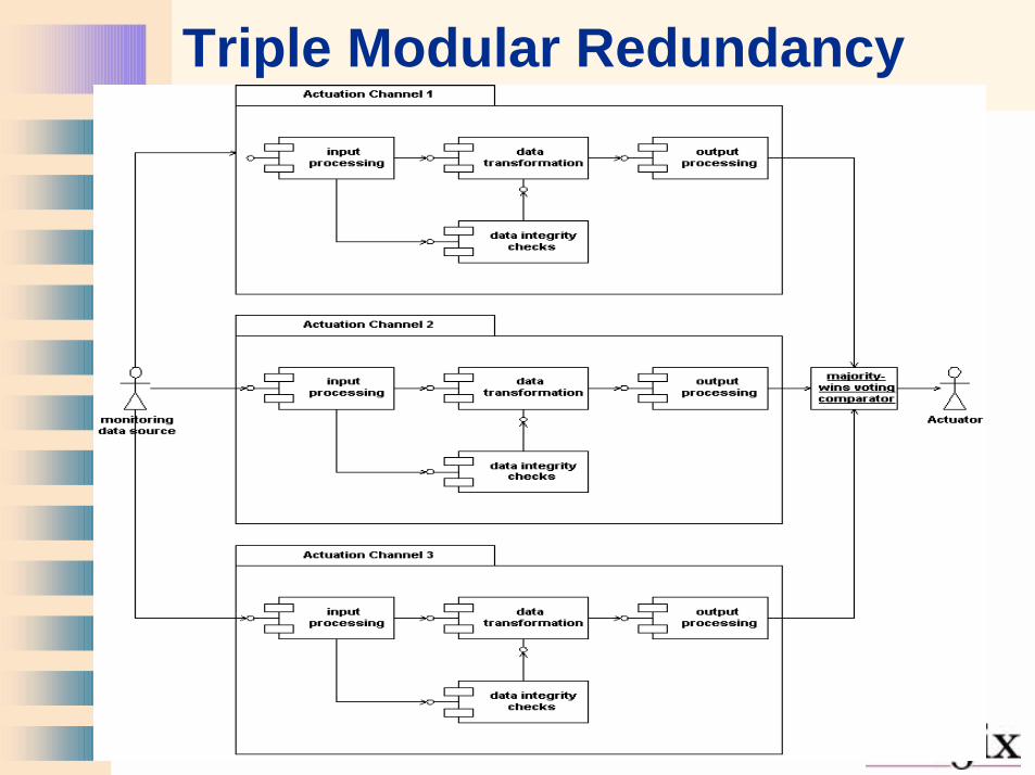
Triple Modular Redundancy
Eight Steps to Safety
1. Identify the Hazards2. Determine the Risks3. Define the Safety Measures4. Create Safe Requirements5. Create Safe Designs6. Implement Safety7. Assure the Safety Process8. Test, Test, Test
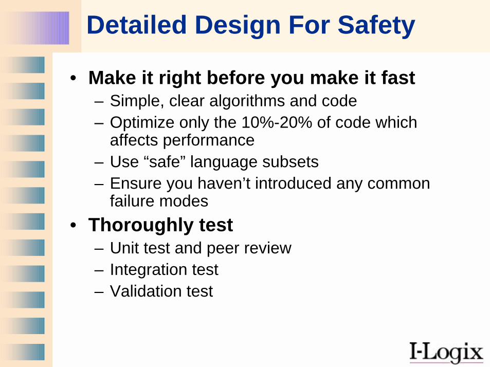
Detailed Design For Safety
• Make it right before you make it fast– Simple, clear algorithms and code– Optimize only the 10%-20% of code which
affects performance– Use “safe” language subsets– Ensure you haven’t introduced any common
failure modes• Thoroughly test
– Unit test and peer review– Integration test– Validation test
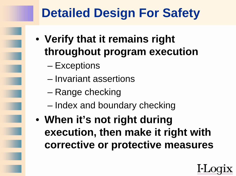
• Verify that it remains right throughout program execution– Exceptions– Invariant assertions– Range checking– Index and boundary checking
• When it’s not right during execution, then make it right with corrective or protective measures
Detailed Design For Safety
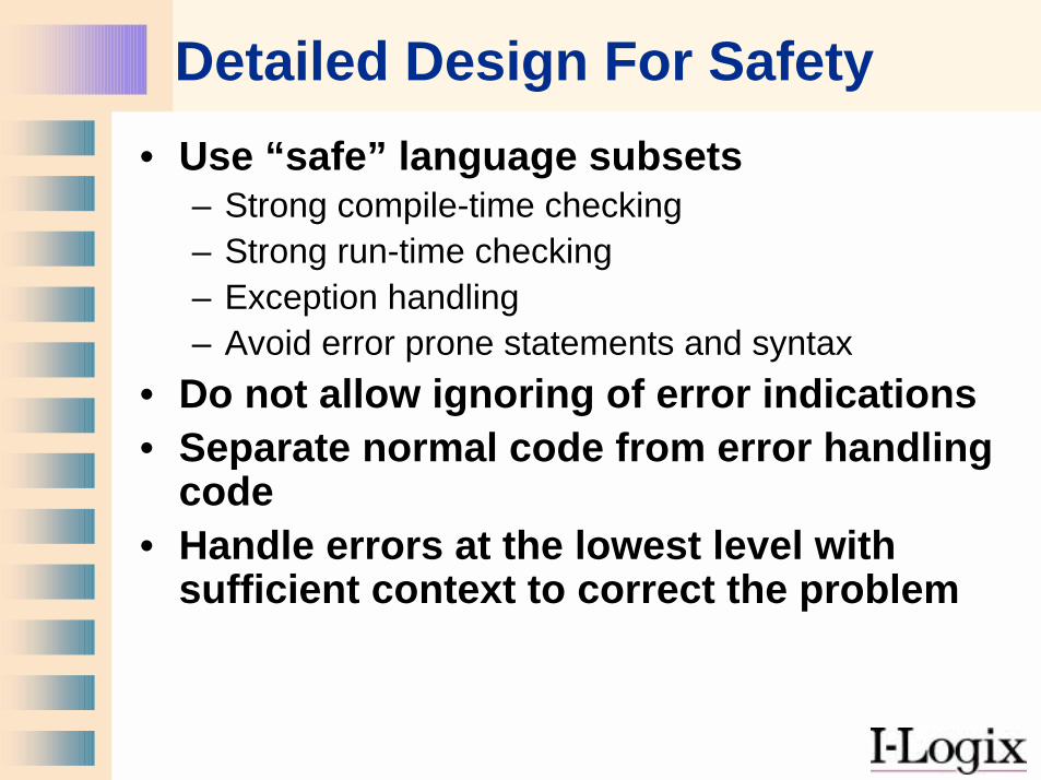
Detailed Design For Safety• Use “safe” language subsets
– Strong compile-time checking– Strong run-time checking– Exception handling– Avoid error prone statements and syntax
• Do not allow ignoring of error indications• Separate normal code from error handling
code• Handle errors at the lowest level with
sufficient context to correct the problem
Detailed Design For Safety
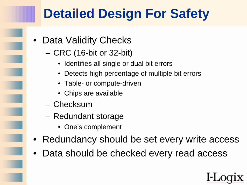
• Data Validity Checks– CRC (16-bit or 32-bit)
• Identifies all single or dual bit errors• Detects high percentage of multiple bit errors• Table- or compute-driven • Chips are available
– Checksum– Redundant storage
• One’s complement
• Redundancy should be set every write access• Data should be checked every read access
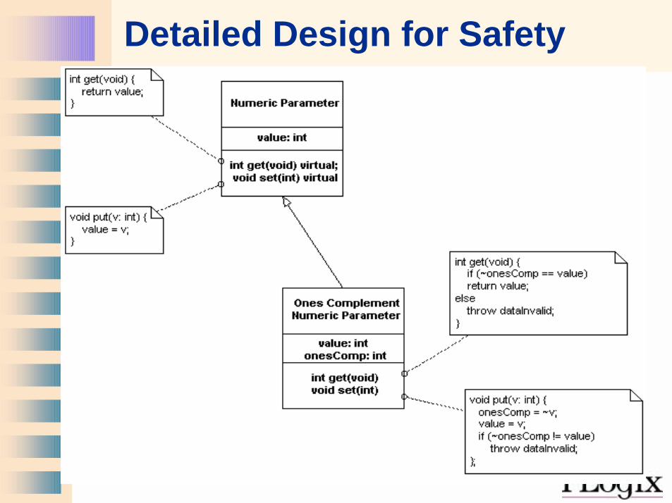
Detailed Design for Safety
Eight Steps to Safety
1. Identify the Hazards2. Determine the Risks3. Define the Safety Measures4. Create Safe Requirements5. Create Safe Designs6. Implement Safety7. Assure the Safety Process8. Test, Test, Test
Safety Process (Development)
• Do Hazard Analysis early and often• Track safety measures from hazard
analysis to– Requirements Specification– Design– Code– Validation Tests
• Test safety measures with fault seeding
Safety Process (Deployment)
• Install Safely– Ensure proper means are used to set up
system– Safety measures are installed and checked
• Deploy Safely– Ensure safety measures are periodically
checked and serviced– Do not turn off safety measures (see Bophal)
• Decommission Safely– Removal of hazardous materials
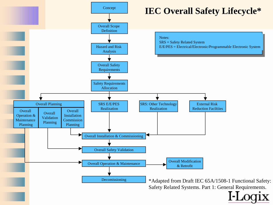
IEC Overall Safety Lifecycle*IEC Overall Safety Lifecycle*
*Adapted from Draft IEC 65A/1508-1 Functional Safety:Safety Related Systems. Part 1: General Requirements.
Concept
Overall Scope Definition
Hazard and Risk Analysis
Overall Safety Requirements
Safety RequirementsAllocation
Overall Planning SRS E/E/PES Realization
SRS: Other TechnologyRealization
External Risk Reduction FaciltiiesOverall
Operation &Maintenance
Planning
Overall ValidationPlanning
OverallInstallation
CommissionPlanning
Overall Installation & Commissioning
Overall Safety Validation
Overall Operation & Maintenance Overall Modification& Retrofit
Decomissioning
Notes:SRS = Safety Related SystemE/E/PES = Electrical/Electronic/Programmable Electronic System
Eight Steps to Safety
1. Identify the Hazards2. Determine the Risks3. Define the Safety Measures4. Create Safe Requirements5. Create Safe Designs6. Implement Safety7. Assure the Safety Process8. Test, Test, Test
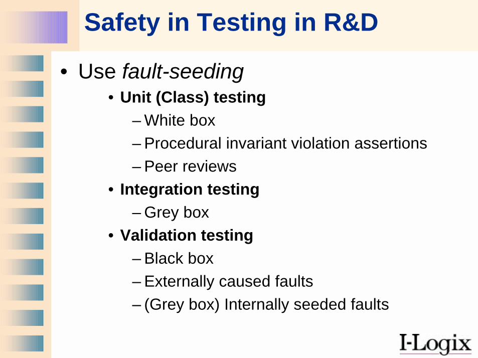
Safety in Testing in R&D
• Use fault-seeding• Unit (Class) testing
– White box– Procedural invariant violation assertions– Peer reviews
• Integration testing– Grey box
• Validation testing– Black box– Externally caused faults– (Grey box) Internally seeded faults
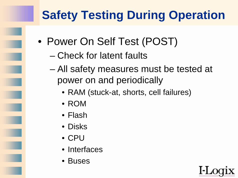
Safety Testing During Operation
• Power On Self Test (POST)– Check for latent faults– All safety measures must be tested at
power on and periodically• RAM (stuck-at, shorts, cell failures)• ROM• Flash• Disks• CPU• Interfaces• Buses
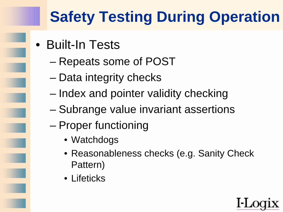
Safety Testing During Operation
• Built-In Tests– Repeats some of POST– Data integrity checks– Index and pointer validity checking– Subrange value invariant assertions– Proper functioning
• Watchdogs• Reasonableness checks (e.g. Sanity Check
Pattern)• Lifeticks

A simplified Example:A Linear Accelerator
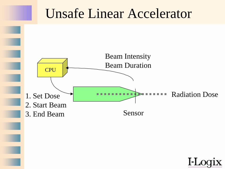
CPU
Sensor
Beam IntensityBeam Duration
1. Set Dose2. Start Beam3. End Beam
Unsafe Linear Accelerator
Radiation Dose
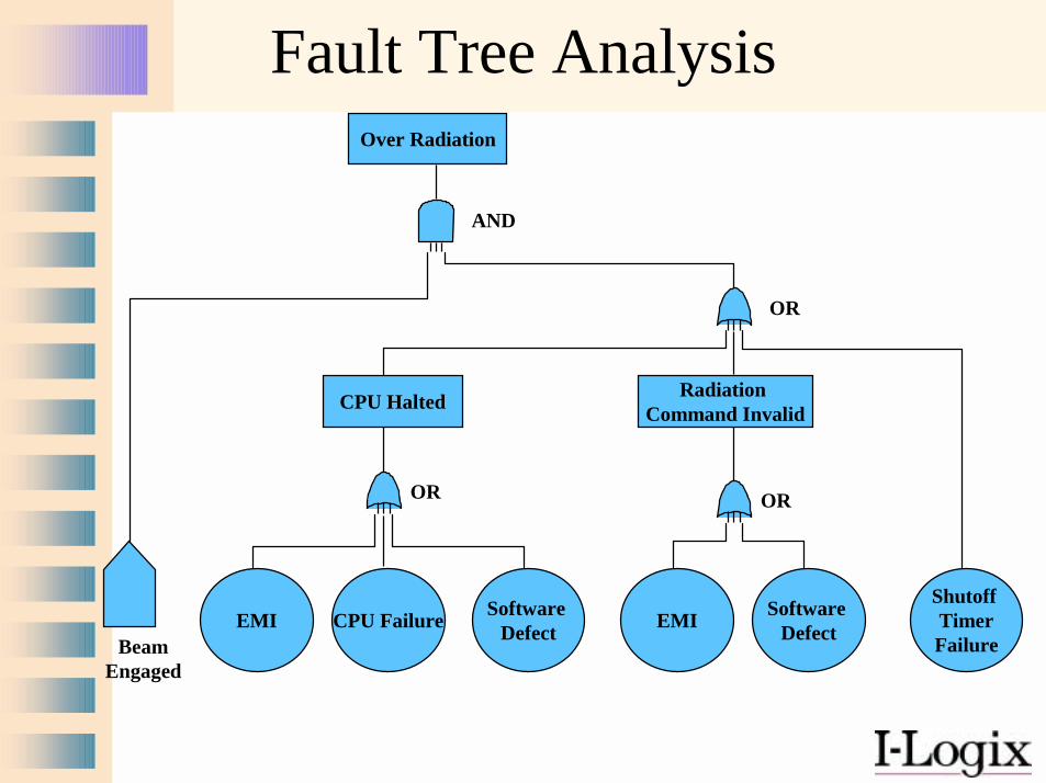
Fault Tree AnalysisOver Radiation
Software Defect
OR
AND
EMI
CPU Halted
CPU FailureBeam
Engaged
Radiation Command Invalid
Software DefectEMI
OR
OR
Shutoff TimerFailure
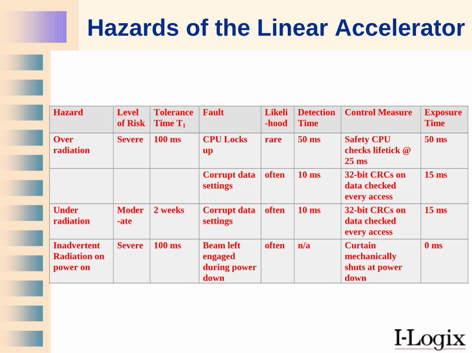
Hazards of the Linear Accelerator
Hazard Levelof Risk
ToleranceTime T1
Fault Likeli-hood
DetectionTime
Control Measure ExposureTime
Overradiation
Severe 100 ms CPU Locksup
rare 50 ms Safety CPUchecks lifetick @25 ms
50 ms
Corrupt datasettings
often 10 ms 32-bit CRCs ondata checkedevery access
15 ms
Underradiation
Moder-ate
2 weeks Corrupt datasettings
often 10 ms 32-bit CRCs ondata checkedevery access
15 ms
InadvertentRadiation onpower on
Severe 100 ms Beam leftengagedduring powerdown
often n/a Curtainmechanicallyshuts at powerdown
0 ms
CPU
Sensor
Beam IntensityBeam Duration
1. Set Dose2. Start Beam3. End Beam
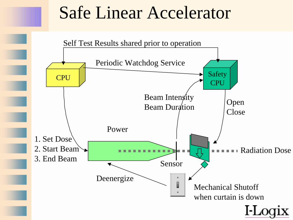
Safe Linear Accelerator
Radiation Dose
SafetyCPU
Periodic Watchdog Service
OpenClose
Self Test Results shared prior to operation
Power
DeenergizeMechanical Shutoffwhen curtain is down
Conclusion
• Safety is a system issue• It is cheaper and more effective to
include safety early on then to add it later
• Safety architectures provide programming-in-the-large safety
• Safe coding rules and detailed design provide programming-in-the-small safety