Embed Size (px)
Citation preview
NASA/TM–2015–218492
Safety Case Patterns:Theory and Applications
Ewen W. DenneySGT, Inc.Ames Research Center, Moffett Field, California
Ganesh J. PaiSGT, Inc.Ames Research Center, Moffett Field, California
February 2015
https://ntrs.nasa.gov/search.jsp?R=20150004086 2018-05-27T02:27:23+00:00Z

NASA STI Program . . . in Profile
Since its founding, NASA has been dedicated tothe advancement of aeronautics and spacescience. The NASA scientific and technicalinformation (STI) program plays a key part inhelping NASA maintain this important role.
The NASA STI Program operates under theauspices of the Agency Chief InformationOfficer. It collects, organizes, provides forarchiving, and disseminates NASA’s STI. TheNASA STI Program provides access to theNASA Aeronautics and Space Database and itspublic interface, the NASA Technical ReportServer, thus providing one of the largestcollection of aeronautical and space science STIin the world. Results are published in bothnon-NASA channels and by NASA in the NASASTI Report Series, which includes the followingreport types:
• TECHNICAL PUBLICATION. Reports ofcompleted research or a major significantphase of research that present the results ofNASA programs and include extensive data ortheoretical analysis. Includes compilations ofsignificant scientific and technical data andinformation deemed to be of continuingreference value. NASA counterpart ofpeer-reviewed formal professional papers, buthaving less stringent limitations on manuscriptlength and extent of graphic presentations.
• TECHNICAL MEMORANDUM.Scientific and technical findings that arepreliminary or of specialized interest, e.g.,quick release reports, working papers, andbibliographies that contain minimalannotation. Does not contain extensiveanalysis.
• CONTRACTOR REPORT. Scientific andtechnical findings by NASA-sponsoredcontractors and grantees.
• CONFERENCE PUBLICATION.Collected papers from scientific and technicalconferences, symposia, seminars, or othermeetings sponsored or co-sponsored byNASA.
• SPECIAL PUBLICATION. Scientific,technical, or historical information fromNASA programs, projects, and missions, oftenconcerned with subjects having substantialpublic interest.
• TECHNICAL TRANSLATION. English-language translations of foreign scientific andtechnical material pertinent to NASA’smission.
Specialized services also include creating customthesauri, building customized databases, andorganizing and publishing research results.
For more information about the NASA STIProgram, see the following:
• Access the NASA STI program home page at
http://www.sti.nasa.gov
• E-mail your question via the Internet to
• Fax your question to the NASA STI Help
Desk at 443-757-5803
• Phone the NASA STI Help Desk at
443-757-5802
• Write to:
NASA STI Help Desk
NASA Center for AeroSpace Information
7115 Standard Drive
Hanover, MD 21076–1320
NASA/TM–2015–218492
Safety Case Patterns:Theory and Applications
Ewen W. DenneySGT, Inc.Ames Research Center, Moffett Field, California
Ganesh J. PaiSGT, Inc.Ames Research Center, Moffett Field, California
National Aeronautics and
Space Administration
Ames Research Center
Moffett Field, California 94035-1000
February 2015

Acknowledgments
This work has been funded by the AFCS element of the SSAT project in the Aviation Safety Program of
the NASA Aeronautics Research Mission Directorate. Any errors in this report are those of the authors.
The use of trademarks or names of manufacturers in this report is for accurate reporting and does not constitute an
offical endorsement, either expressed or implied, of such products or manufacturers by the National Aeronautics and
Space Administration.
Available from:
NASA Center for AeroSpace Information
7115 Standard Drive
Hanover, MD 21076-1320
443-757-5802
Abstract
We develop the foundations for a theory of patterns of safety case argument structures,
clarifying the concepts involved in pattern specification, including choices, labeling, and
well-founded recursion. We specify six new patterns in addition to those existing in the
literature. We give a generic way to specify the data required to instantiate patterns and
a generic algorithm for their instantiation. This generalizes earlier work on generating
argument fragments from requirements tables. We describe an implementation of these
concepts in AdvoCATE, the Assurance Case Automation Toolset, showing how patterns
are defined and can be instantiated. In particular, we describe how our extended notion of
patterns can be specified, how they can be instantiated in an interactive manner, and, finally,
how they can be automatically instantiated using our algorithm.
1
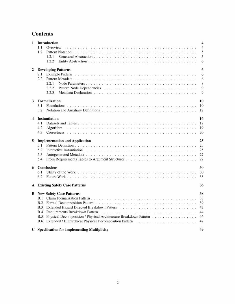
Contents1 Introduction 4
1.1 Overview . . . . . . . . . . . . . . . . . . . . . . . . . . . . . . . . . . . . . . . . . . . . . . . . . . 4
1.2 Pattern Notation . . . . . . . . . . . . . . . . . . . . . . . . . . . . . . . . . . . . . . . . . . . . . . . 5
1.2.1 Structural Abstraction . . . . . . . . . . . . . . . . . . . . . . . . . . . . . . . . . . . . . . . 5
1.2.2 Entity Abstraction . . . . . . . . . . . . . . . . . . . . . . . . . . . . . . . . . . . . . . . . . 6
2 Developing Patterns 62.1 Example Pattern . . . . . . . . . . . . . . . . . . . . . . . . . . . . . . . . . . . . . . . . . . . . . . 6
2.2 Pattern Metadata . . . . . . . . . . . . . . . . . . . . . . . . . . . . . . . . . . . . . . . . . . . . . . 6
2.2.1 Node Parameters . . . . . . . . . . . . . . . . . . . . . . . . . . . . . . . . . . . . . . . . . . 8
2.2.2 Pattern Node Dependencies . . . . . . . . . . . . . . . . . . . . . . . . . . . . . . . . . . . 9
2.2.3 Metadata Declaration . . . . . . . . . . . . . . . . . . . . . . . . . . . . . . . . . . . . . . . 9
3 Formalization 103.1 Foundations . . . . . . . . . . . . . . . . . . . . . . . . . . . . . . . . . . . . . . . . . . . . . . . . . 10
3.2 Notation and Auxiliary Definitions . . . . . . . . . . . . . . . . . . . . . . . . . . . . . . . . . . . . 12
4 Instantiation 164.1 Datasets and Tables . . . . . . . . . . . . . . . . . . . . . . . . . . . . . . . . . . . . . . . . . . . . . 17
4.2 Algorithm . . . . . . . . . . . . . . . . . . . . . . . . . . . . . . . . . . . . . . . . . . . . . . . . . . 19
4.3 Correctness . . . . . . . . . . . . . . . . . . . . . . . . . . . . . . . . . . . . . . . . . . . . . . . . . 20
5 Implementation and Application 255.1 Pattern Definition . . . . . . . . . . . . . . . . . . . . . . . . . . . . . . . . . . . . . . . . . . . . . . 25
5.2 Interactive Instantiation . . . . . . . . . . . . . . . . . . . . . . . . . . . . . . . . . . . . . . . . . . 25
5.3 Autogenerated Metadata . . . . . . . . . . . . . . . . . . . . . . . . . . . . . . . . . . . . . . . . . . 27
5.4 From Requirements Tables to Argument Structures . . . . . . . . . . . . . . . . . . . . . . . . . . . 27
6 Conclusions 306.1 Utility of the Work . . . . . . . . . . . . . . . . . . . . . . . . . . . . . . . . . . . . . . . . . . . . . 30
6.2 Future Work . . . . . . . . . . . . . . . . . . . . . . . . . . . . . . . . . . . . . . . . . . . . . . . . . 33
A Existing Safety Case Patterns 36
B New Safety Case Patterns 38B.1 Claim Formalization Pattern . . . . . . . . . . . . . . . . . . . . . . . . . . . . . . . . . . . . . . . . 38
B.2 Formal Decomposition Pattern . . . . . . . . . . . . . . . . . . . . . . . . . . . . . . . . . . . . . . 39
B.3 Extended Hazard Directed Breakdown Pattern . . . . . . . . . . . . . . . . . . . . . . . . . . . . . 42
B.4 Requirements Breakdown Pattern . . . . . . . . . . . . . . . . . . . . . . . . . . . . . . . . . . . . . 44
B.5 Physical Decomposition / Physical Architecture Breakdown Pattern . . . . . . . . . . . . . . . . . 46
B.6 Extended / Hierarchical Physical Decomposition Pattern . . . . . . . . . . . . . . . . . . . . . . . 47
C Specification for Implementing Multiplicity 49
2
List of Figures1 Claim formalization pattern . . . . . . . . . . . . . . . . . . . . . . . . . . . . . . . . . . . . . . . . 7
2 Formal methods upper ontology . . . . . . . . . . . . . . . . . . . . . . . . . . . . . . . . . . . . . . 8
3 Grammar for attribute declaration in Goal Structuring Notation (GSN) nodes . . . . . . . . . . . . 9
4 GSN for patterns . . . . . . . . . . . . . . . . . . . . . . . . . . . . . . . . . . . . . . . . . . . . . . 11
5 Multiplicity Condition Example . . . . . . . . . . . . . . . . . . . . . . . . . . . . . . . . . . . . . . 14
6 Invalid Loop Examples . . . . . . . . . . . . . . . . . . . . . . . . . . . . . . . . . . . . . . . . . . . 15
7 Illustrating data-oriented pattern semantics . . . . . . . . . . . . . . . . . . . . . . . . . . . . . . . 16
8 Illustrating Data Tables . . . . . . . . . . . . . . . . . . . . . . . . . . . . . . . . . . . . . . . . . . . 18
9 High-level algorithm for pattern instantiation (from [1]) . . . . . . . . . . . . . . . . . . . . . . . . 21
10 Example Pattern and Dataset . . . . . . . . . . . . . . . . . . . . . . . . . . . . . . . . . . . . . . . 21
11 Steps in the instantiation of the example pattern in Figure 10a using the dataset of Figure 10c. . . 24
12 AdvoCATE Pattern Documentation Panel Screenshot . . . . . . . . . . . . . . . . . . . . . . . . . 26
13 Swift UAS Safety Case Fragment . . . . . . . . . . . . . . . . . . . . . . . . . . . . . . . . . . . . . 27
14 Screenshot of AdvoCATE Formalization Interface . . . . . . . . . . . . . . . . . . . . . . . . . . . 28
15 Interface to interactively supply the parameters of the CFP . . . . . . . . . . . . . . . . . . . . . . 28
16 AdvoCATE Screenshot of Pattern Instance . . . . . . . . . . . . . . . . . . . . . . . . . . . . . . . 29
17 Requirements breakdown pattern and the corresponding P -table . . . . . . . . . . . . . . . . . . . 31
18 Example instantiation of the requirements breakdown pattern . . . . . . . . . . . . . . . . . . . . . 32
19 Claim formalization pattern . . . . . . . . . . . . . . . . . . . . . . . . . . . . . . . . . . . . . . . . 38
20 Formal decomposition pattern . . . . . . . . . . . . . . . . . . . . . . . . . . . . . . . . . . . . . . . 40
21 Extended hazard directed breakdown pattern . . . . . . . . . . . . . . . . . . . . . . . . . . . . . . 43
22 Requirements breakdown pattern . . . . . . . . . . . . . . . . . . . . . . . . . . . . . . . . . . . . . 45
23 Physical decomposition / physical architecture breakdown pattern . . . . . . . . . . . . . . . . . . 46
24 Extended/Hierarchical physical decomposition pattern . . . . . . . . . . . . . . . . . . . . . . . . . 48
25 Implementation Specification for Multiplicity in AdvoCATE . . . . . . . . . . . . . . . . . . . . . 49
List of Algorithms1 Generic Algorithm for Pattern Instantiation . . . . . . . . . . . . . . . . . . . . . . . . . . . . . . . 22
2 Generic Algorithm for Pattern Instantiation (Verbose tables) . . . . . . . . . . . . . . . . . . . . . 23
3
1 Introduction
1.1 OverviewSafety case patterns are intended to capture repeated structures of successful, i.e., correct, comprehensive and
convincing, arguments that are used within a safety case [2].
The existing notion of a safety case pattern is an argument structure that abstractly captures the reasoning link-
ing certain (types of) claims to the available (types of) evidence, accompanied by clear statements of how/where
the pattern should/should not be applied, i.e., both a prescription and a proscription of its usage. Specifically, a
safety case pattern is documented1 by giving [2], [3]:
• Name: the identifying label of the pattern giving the key principle of its argument.
• Intent: that which the pattern is trying to achieve.
• Motivation: the reasons that gave rise to the pattern.
• Stucture: the abstract structure of the argument given graphically in GSN.
• Participants: each element in the pattern and its description.
• Collaborations: how the interactions of the pattern elements achieve the desired effect of the pattern.
• Applicability: the circumstances under which the pattern could be applied, i.e., the necessary context.
• Consequences: that which remains to be completed after pattern application.
• Implementation: how the pattern should be applied.
• Known Usage: previously knowledge of where and how a pattern has been used.
• Examples: Illustrative examples of pattern application
• Related patterns: Patterns to which a specific pattern is related, i.e., whether it invokes another pattern, or
references it, etc.
Such a descriptive specification is intended to assist in properly deploying a particular pattern. Effectively, safety
case patterns reflect a re-usable approach to safety argumentation; they have been identified as the medium for
capturing [2]:
1. solutions that evolved over time
2. company expertise
3. “tricks of the trade”, i.e., known best practices
4. successful certification approaches.
We may consider these as four sources of safety case patterns. Specific sources of safety case patterns that
are of interest include:
Standards and Processes: Safety standards and safety processes codify (implicitly or explicitly) engineering
knowledge, i.e., steps, procedures, recommendations, practices, rationale and reasoning to ensure that the
outcomes of applying the standard/process meet the intended safety goals. They can potentially contain
all of the four items identified above. We assert that safety case patterns can be created to encapsulate
the methodology and rationale underlying standards/processes; in particular, the steps followed, the data
which must be assembled, the traceability between artifacts, etc. For example, certification according to
DO-178B and DO-178C requires that requirements are decomposed from system requirements, to high-
level requirements, to architecture and low-level requirements, to the source code and then to object code.
NASA Procedural Requirements (NPRs) have similar, but different, processes and corresponding data
requirements.
Reasoning techniques: Just as standards can impose particular decomposition methods, so can formal reason-
ing techniques. Examples include techniques for:
1See Appendix B for examples.
4
• Transferring properties between levels of abstraction: e.g., from model to source code or hardware,
or source to object code. Usually from the abstract to the concrete, but it could be in the opposite
direction.
• The 4 variable model [4] is a specific technique for reasoning about physical quantities in software.
• Interactions: generally arise when considering a system decomposition.
• Decomposition of requirements according to code structure.
Such patterns should also characterize appropriate notions of safety and correctness.
Tools: Tools provide the opportunity to automate all, or part of, the reasoning and methodologies suggested
in standards/processes. For instance, a formal verification tool can encode the reasoning underlying a
specific formal verification method and specifies the inputs, outputs, assumptions, usage processes, and
dependencies (to other tools) in order to apply the method. We contend that the specific reasoning encoded
in a tool can be specified as a safety case pattern.
Property classes: Particular reasoning techniques are appropriate for different classes of properties. A pattern
can describe this, and the relationship to standards, tools, and which other artifacts they relate to. Specific
examples include:
• run-time errors (language safety properties): division by zero, function calls, initializations, arrays
• units, frames (safety properties that need some specification)
• numerical properties: accuracy, stability, robustness (with respect to an arithmetic model, floating
point standard)
• concurrency
• timing
• termination
• liveness
1.2 Pattern NotationThe goal structuring notation (GSN) [5] provides two types of abstractions to support pattern specification:
structural, and entity.
1.2.1 Structural Abstraction
Structural abstraction is achieved mainly through multiplicity, for generalizing n-ary relations between GSN
elements, and optionality, for capturing alternative or optional relationships between GSN elements. Both operate
on the links in-context-of, and is-solved-by.
Multiplicity: Two multiplicity options exist for these relations:
1. many, implying zero or more, is denoted as an annotated solid ball (●) placed on the arrow showing
the relation, with the cardinality of the multiplicity represented by the annotation.
2. optional, implying zero or one, is denoted as a hollow ball (○) placed on the arrow showing the
relations.
Choice: Choice2 is given as an annotated, solid diamond3 (◆) placed on either of the inContextOf and is-SolvedBy links with the annotation representing a k-of-m choice, where k ≥ 1. Choice and multiplicity
can be combined; placing the multiplicity symbols prior to the option describes a multiplicity over all the
options. This is equivalent to placing the multiplicity symbol on all the options after the option symbol [5].
We generalize multiplicity and optionality to arbitrary ranges l . . . h and assume, without loss of generality,
that all links and choices have an associated range (see Definition 3.2 and Appendix C).
2Referred to as optionality in the GSN standard, and not to be confused with optional multiplicity.3The GSN standard uses a more elongated symbol than we do here.
5
In addition to these, there are (limited) examples of the use of an iteration or recursion abstraction in the
literature [6], although it is not formally given in the GSN standard. Recursion, in the context of patterns,
expresses the notion that a pattern (or a part of it) can itself be repeated and unrolled, e.g., as part of an optional
relation or a larger pattern. Recursion abstractions may or may not be labeled with an expression giving the
number of iterations to be applied in a concrete instance, i.e., the number of times the loop is unrolled in an
instance of the pattern. No annotations indicate that the iteration can be unrolled arbitrarily many times. Here,
we encode the number of times to unroll the loop in a data structure that also contains the data to be used when
instantiating a pattern (Section 4).
1.2.2 Entity Abstraction
For entity abstraction, GSN provides the notions of an uninstantiated entity and an undeveloped and uninstan-tiated entity, denoted by a triangle (△) and a diamond with a horizontal line (�) respectively, appended to the
relevant notation of the GSN entity.
Uninstantiated entities refer to abstract parametrized elements that, when instantiated, contain concrete val-
ues of the parameters and replace the abstraction. Undeveloped and uninstantiated entities refer to uninstantiated
entities which are also to be developed. Therefore, after instantiation the abstraction is replaced with a concrete,
but undeveloped, element4.
2 Developing PatternsWe provide a revised notion of a safety case pattern, as a combination of the following items:
1. An abstract argument structure, together with its documentation elements, i.e., the existing format for
documenting safety case patterns
2. Typed pattern variables and pattern metadata
Patterns can be instantiated, transformed, and composed. These concepts are complementary to, and enhance,
the existing notion of a safety case pattern. In this report we concentrate on instantiation and defer description of
the other operations to a future report.
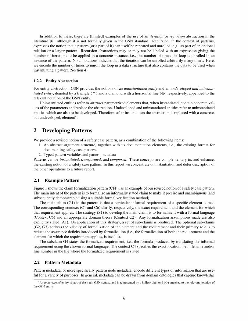
2.1 Example PatternFigure 1 shows the claim formalization pattern (CFP), as an example of our revised notion of a safety case pattern.
The main intent of the pattern is to formalize an informally stated claim to make it precise and unambiguous (and
subsequently demonstrable using a suitable formal verification method).
The main claim (G1) in the pattern is that a particular informal requirement of a specific element is met.
The corresponding contexts (C1 and C6) clarify, respectively, the exact requirement and the element for which
that requirement applies. The strategy (S1) to develop the main claim is to formalize it with a formal language
(Context C5) and an appropriate domain theory (Context C2). Any formalization assumptions made are also
explicitly stated (A1). On application of this strategy, a set of sub-claims is produced. The optional sub-claims
(G2, G3) address the validity of formalization of the element and the requirement and their primary role is to
reduce the assurance deficits introduced by formalization (i.e., the formalization of both the requirement and the
element for which the requirement applies, is invalid).
The subclaim G4 states the formalized requirement, i.e., the formula produced by translating the informal
requirement using the chosen formal language. The context C4 specifies the exact location, i.e., filename and/or
line number in the file where the formalized requirement is stated.
2.2 Pattern MetadataPattern metadata, or more specifically pattern node metadata, encode different types of information that are use-
ful for a variety of purposes. In general, metadata can be drawn from domain ontologies that capture knowledge
4An undeveloped entity is part of the main GSN syntax, and is represented by a hollow diamond (◇) attached to the relevant notation of
the GSN entity.
6
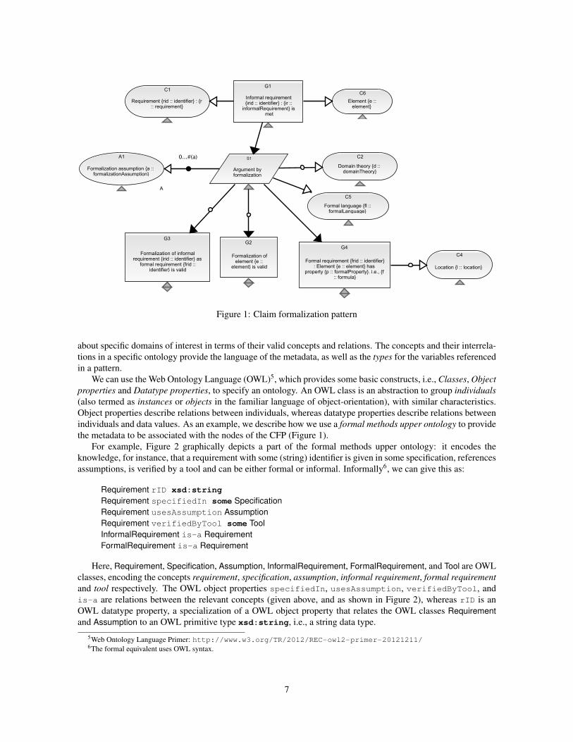
Figure 1: Claim formalization pattern
about specific domains of interest in terms of their valid concepts and relations. The concepts and their interrela-
tions in a specific ontology provide the language of the metadata, as well as the types for the variables referenced
in a pattern.
We can use the Web Ontology Language (OWL)5, which provides some basic constructs, i.e., Classes, Objectproperties and Datatype properties, to specify an ontology. An OWL class is an abstraction to group individuals(also termed as instances or objects in the familiar language of object-orientation), with similar characteristics.
Object properties describe relations between individuals, whereas datatype properties describe relations between
individuals and data values. As an example, we describe how we use a formal methods upper ontology to provide
the metadata to be associated with the nodes of the CFP (Figure 1).
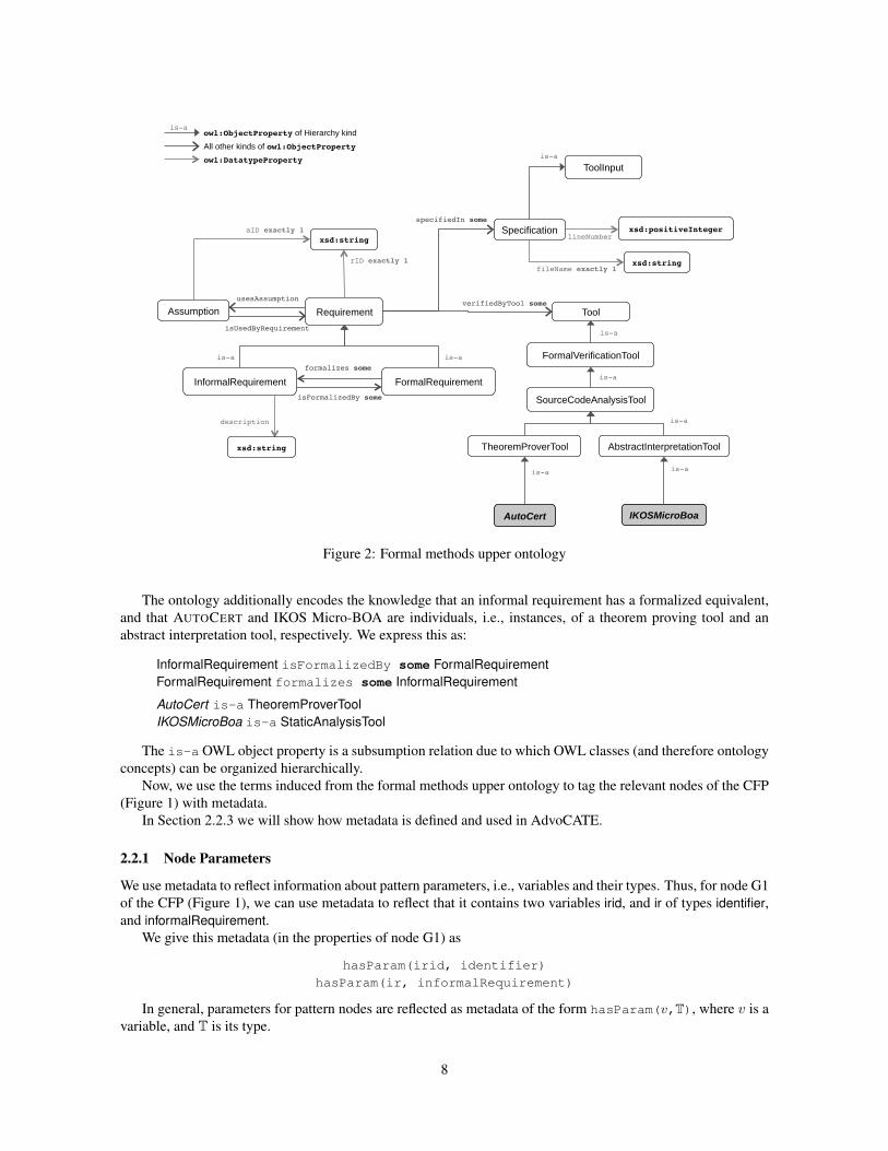
For example, Figure 2 graphically depicts a part of the formal methods upper ontology: it encodes the
knowledge, for instance, that a requirement with some (string) identifier is given in some specification, references
assumptions, is verified by a tool and can be either formal or informal. Informally6, we can give this as:
Requirement rID xsd:stringRequirement specifiedIn some SpecificationRequirement usesAssumption AssumptionRequirement verifiedByTool some ToolInformalRequirement is-a RequirementFormalRequirement is-a Requirement
Here, Requirement, Specification, Assumption, InformalRequirement, FormalRequirement, and Tool are OWL
classes, encoding the concepts requirement, specification, assumption, informal requirement, formal requirementand tool respectively. The OWL object properties specifiedIn, usesAssumption, verifiedByTool, and
is-a are relations between the relevant concepts (given above, and as shown in Figure 2), whereas rID is an
OWL datatype property, a specialization of a OWL object property that relates the OWL classes Requirementand Assumption to an OWL primitive type xsd:string, i.e., a string data type.
5Web Ontology Language Primer: http://www.w3.org/TR/2012/REC-owl2-primer-20121211/6The formal equivalent uses OWL syntax.
7
Requirement
InformalRequirement FormalRequirement
is-a is-a
formalizes some
xsd:string
rID exactly 1
isFormalizedBy some
Assumption usesAssumption
aID exactly 1 Specification
verifiedByTool some
specifiedIn some
is-aowl:ObjectProperty of Hierarchy kind All other kinds of owl:ObjectPropertyowl:DatatypeProperty
FormalVerificationTool
TheoremProverTool AbstractInterpretationTool
is-a
AutoCert
is-a
IKOSMicroBoa
is-a
ToolInput is-a
Tool
is-a
xsd:positiveIntegerlineNumber
xsd:stringfileName exactly 1
description
isUsedByRequirement
SourceCodeAnalysisTool
is-a
xsd:string
Figure 2: Formal methods upper ontology
The ontology additionally encodes the knowledge that an informal requirement has a formalized equivalent,
and that AUTOCERT and IKOS Micro-BOA are individuals, i.e., instances, of a theorem proving tool and an
abstract interpretation tool, respectively. We express this as:
InformalRequirement isFormalizedBy some FormalRequirementFormalRequirement formalizes some InformalRequirement
AutoCert is-a TheoremProverToolIKOSMicroBoa is-a StaticAnalysisTool
The is-a OWL object property is a subsumption relation due to which OWL classes (and therefore ontology
concepts) can be organized hierarchically.
Now, we use the terms induced from the formal methods upper ontology to tag the relevant nodes of the CFP
(Figure 1) with metadata.
In Section 2.2.3 we will show how metadata is defined and used in AdvoCATE.
2.2.1 Node Parameters
We use metadata to reflect information about pattern parameters, i.e., variables and their types. Thus, for node G1
of the CFP (Figure 1), we can use metadata to reflect that it contains two variables irid, and ir of types identifier,and informalRequirement.
We give this metadata (in the properties of node G1) as
hasParam(irid, identifier)
hasParam(ir, informalRequirement)
In general, parameters for pattern nodes are reflected as metadata of the form hasParam(v,T), where v is a
variable, and T is its type.
8
2.2.2 Pattern Node Dependencies
We use metadata also to reflect dependencies that exist between certain types of nodes. Thus, for the goal nodes
G1 and G4 of the CFP (Figure 1), one dependency is that the claim in G4 formalizes the claim in G1. Although
this is captured intuitively by the structure, we can also represent this as metadata associated with the goal node
G4. Thus,
• Claim G1: This node is tagged with informalRequirement to indicate that it is an informal require-
ment, with identifier frid, and isFormalizedBy(frid) to indicate that it is formalized by a formal
requirement with identifier frid.
• Claim G4: This node is tagged with formalRequirement to indicate that it is a formal requirement with
identifier frid, and with formalizes(irid), to indicate that it formalizes the informal requirement with
identifier irid.
Additionally, the node is tagged with verifiedByTool(tool), to indicate the tool that will be called
to verify the requirement.7 To support the call to the verification tool additional metadata is appended to
the node. We specify the location of the formal requirement using specifiedIn(location), where a
location is possibly a file f and a line number n in that file.
Depending on the tool and/or language used, additional metadata can be added. For example, when using
the AUTOCERT theorem proving tool, additional metadata are drawn from the concepts and relations of the
AUTOCERT verification methodology ontology (not shown here), such as schema, autocertAxiom, etc.
2.2.3 Metadata Declaration
Metadata is associated with individual nodes (rather than globally with the entire argument or pattern). Each
node has a set of associated attributes, which are declared and can be parameterized over parameters of specific
types.
Nodes have instances of attributes with values that comply with the type of the parameter (which can itself
depend on the node). In general, we draw these parameter values from a domain ontology (See Section 2.2, for
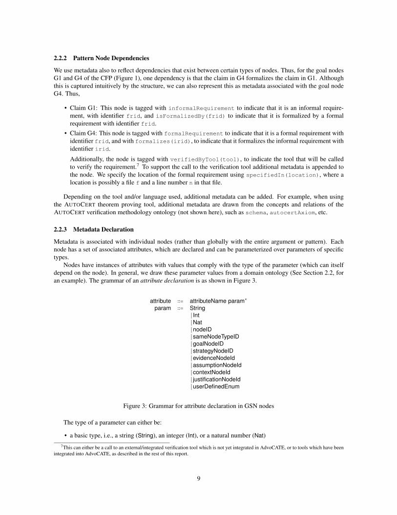
an example). The grammar of an attribute declaration is as shown in Figure 3.
attribute ∶∶= attributeName param∗
param ∶∶= String∣ Int∣Nat∣nodeID∣ sameNodeTypeID∣goalNodeID∣ strategyNodeID∣evidenceNodeId∣assumptionNodeId∣ contextNodeId∣ justificationNodeId∣userDefinedEnum
Figure 3: Grammar for attribute declaration in GSN nodes
The type of a parameter can either be:
• a basic type, i.e., a string (String), an integer (Int), or a natural number (Nat)
7This can either be a call to an external/integrated verification tool which is not yet integrated in AdvoCATE, or to tools which have been
integrated into AdvoCATE, as described in the rest of this report.
9
• a node type, which can be used as parameters in three different ways:
– NodeID: any kind of node
– sameNodeTypeID: the parameter must be the identifier of a node of the same type as the node with
the attribute.
– Specific node parameter types, which allow specification of a node of a given type: assumptionN-odeID, contextNodeID, evidenceNodeID, goalNodeID, justificationNodeID, strategyNodeID.
• A user-defined enumeration (userDefinedEnum): for example, we can define the parameter types
severity ∶∶= catastrophic ∣ hazardous ∣ major ∣ minor ∣ noSafetyEffect
likelihood ∶∶= frequent ∣ probable ∣ remote ∣ extremelyRemote ∣ extremelyImprobable
to define the parametrized attribute risk(severity, likelihood). Then, we can give an attribute instance as:
risk(severity(catastrophic), likelihood(extremelyImprobable)). We will just use “attribute” when it is clear
from the context whether we mean attribute instance or attribute declaration. Note that we do not force the
values of different enumerations to be distinct.
Additionally, as mentioned in Section 2.2.2, we can add metadata reflecting pattern node dependencies. For
example, to reflect the notion that a particular node in a pattern formalizes another node of the same type in that
pattern, we can specify the attribute formalizes(sameNodeTypeID) as the metadata for that node.
As mentioned in Section 2.2.1, we use metadata to reflect information about pattern parameters. We specify
the following reserved attributes as metadata for the data nodes, and instances, of a pattern P , with parameter
identifiers Id , taking values v ∈ V of type T .
1. We add the attribute hasParam(Id , T ), as derived metadata to the data nodes in the pattern.
2. To the corresponding instance nodes, we add the derived metadata instantiatesPatternNode(PatternName ,
PatternNodeID), and instantiatesParameter(Param , Val ), where PatternNodeID is the node iden-
tifier of the data node being instantiated, and each parameter instantiated is recorded in a separate attribute.
3 FormalizationIn this section, first we extend an earlier definition of a argument structure [1], [7], which omitted a labeling
function for node contents that we now include. Then, we give a formal definition of a pattern, clarifying
conditions on multiplicity and recursion. Next, we give a formal semantics to patterns as the set of their concrete
instances, via a notion of pattern refinement.
3.1 FoundationsDefinition 3.1 (Argument Structure). An argument structure, S, is a tuple8 ⟨N, l,→⟩, comprising a set of
nodes, N , a family of labeling functions, lX , where X ∈ {t, d,m, s}, giving the node fields type, description,
attributes, i.e., metadata, and status; and → is the connector relation between nodes. Let {G,S,E ,A,J ,C}be the node types goal, strategy, evidence, assumption, justification, and context respectively. Then, lt ∶ N →{G,S,E ,A,J ,C} gives node types, ld ∶ N → string gives node descriptions, lm ∶ N → A∗ gives node instance
attributes, and ls ∶ N → P({tbd}) gives node development status.
We define the transitive closure, →∗∶ ⟨N,N⟩, in the usual way. We require the connector relation to form a
finite forest with the operation isrootN(r) checking if the node r is a root of the forest9.
Furthermore, the following structural conditions must be met:
8This definition, and the following, extend those of [7] and [8] with the formalization of metadata and node fields introduced in [9]. Note
that we define a strict notion of argument and, subsequently, pattern, where goals require intermediate strategies, and separate goals cannot
share evidence. In practice, both these conditions are often violated, and can be captured with a more relaxed definition. Additionally, note
that this definition does not consider the notions of modularity and hierarchy [10] which introduce additional node types and constraints on
links between node types.9A full argument structure has a single root.
10
m: l..h
m: l..h
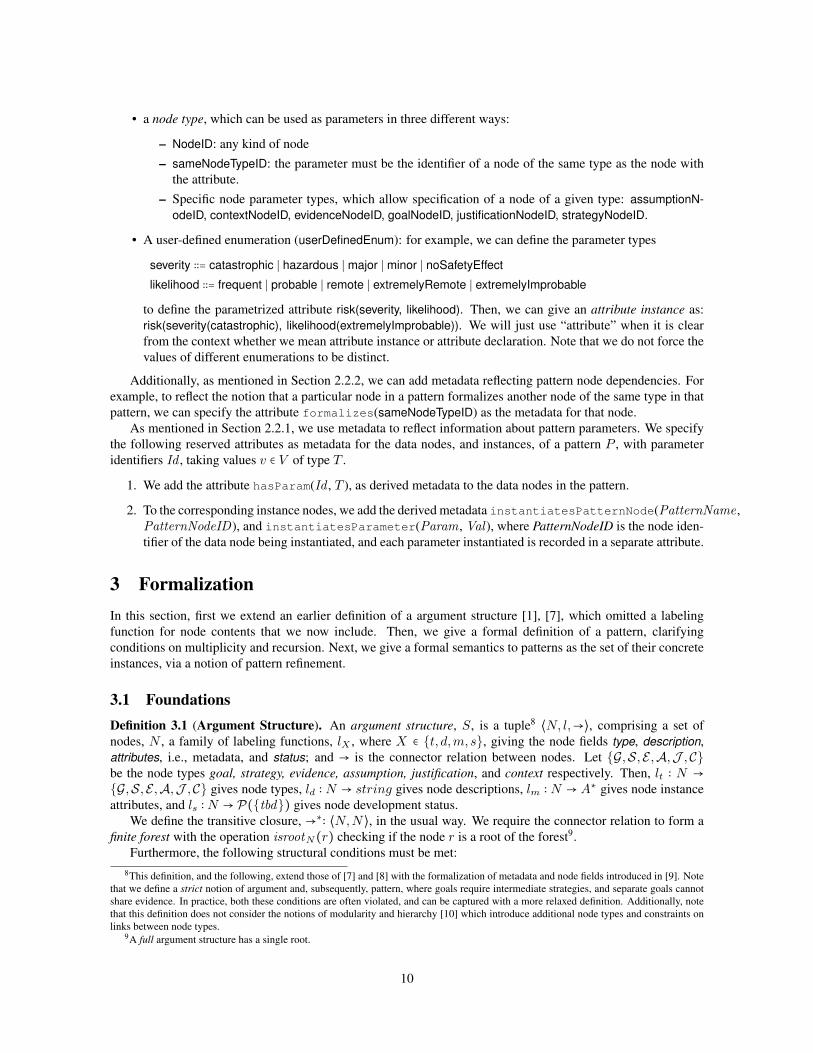
Figure 4: Formalized abstractions in GSN for pattern specification
1. Each part of the argument structure has a root goal: isrootN(r) ⇒ lt(r) = G2. Connectors only leave goals or strategies: n →m ⇒ lt(n) ∈ {G,S}3. Goals cannot connect to other goals: (n →m) ∧ [lt(n) = G] ⇒ lt(m) ∈ {S,E ,A,J ,C}4. Strategies cannot connect to other strategies or evidence: (n →m) ∧ [lt(n) = S] ⇒ lt(m) ∈ {G,A,J ,C}5. Only goals and strategies can be undeveloped: tbd ∈ ls(n) ⇒ lt(n) ∈ {G,S}.
Metadata is defined in Section 2.2.3. The definitions of argument structure and pattern (below) implicitly
assume that node metadata is well-formed, which implies that all node references exist. However, it is possible
that during instantiation a partially developed argument might have metadata with missing references, but still
be structurally sound. Thus it is useful to relax the condition on metadata and introduce a notion of structuralwell-formedness when we need to make the distinction.
To move from arguments to patterns, we remove the acyclicity condition, and use hypergraphs rather than
graphs.
Definition 3.2 (Argument Pattern). An argument pattern (or pattern, for short), P , is a tuple ⟨N, l, p,m, c,→⟩,where ⟨N,→⟩ is a directed hypergraph10 in which each hyperedge has a single source and possibly multiple
targets, l is a family of labeling functions, lX , where X ∈ {t, d,m, s}, and p, m, and c are additional labeling
functions. The structural conditions from Definition 3.1 hold, as well as the conditions below:
1. lX , where X ∈ {t, d,m} is as in Definition 3.1 above. We have ls ∶ N → P({tbd , tbi}), retaining the tbdrestriction from Def 3.1.
2. p is a parameter label on nodes, p ∶ N ⇀ Id × T , giving the parameter identifier and type. Without loss of
generality, we assume that nodes have at most a single parameter
3. m ∶ (→) × N ⇀ (N × N) gives11 the label on the ith outgoing connector12. Without loss of generality,
we assume that multiplicity only applies to outgoing connectors. Note that this includes the case of a
single (non-choice) link. If it is ⟨L,H⟩ then multiplicity has the range L..H , where L ≤ H . An optional
connector has range 0..1.
4. c ∶ (→) → N ×N, gives the “L..H of n” choice range. We give ranges and omit the n.
Intuitively, we expect the bounds on choices to be within the number of legs of the choice, i.e., if a →{b1,⋯, bn} and c maps the link to ⟨L,H⟩ then L < n ≤H .
10A graph where edges connect multiple vertices.11Here we treat the link mapping→ as a set.12Although siblings are unordered in GSN, it is convenient to assume an ordering.
11
Note that, as for argument structures, we do not assume a unique root for patterns. However, the implemen-
tation does assume this.
Formally, we assume all choices/multiplicities have labels, but do not display them if trivial. See Appendix C
for the multiplicity specification used in the implementation, which is described in Section 5.
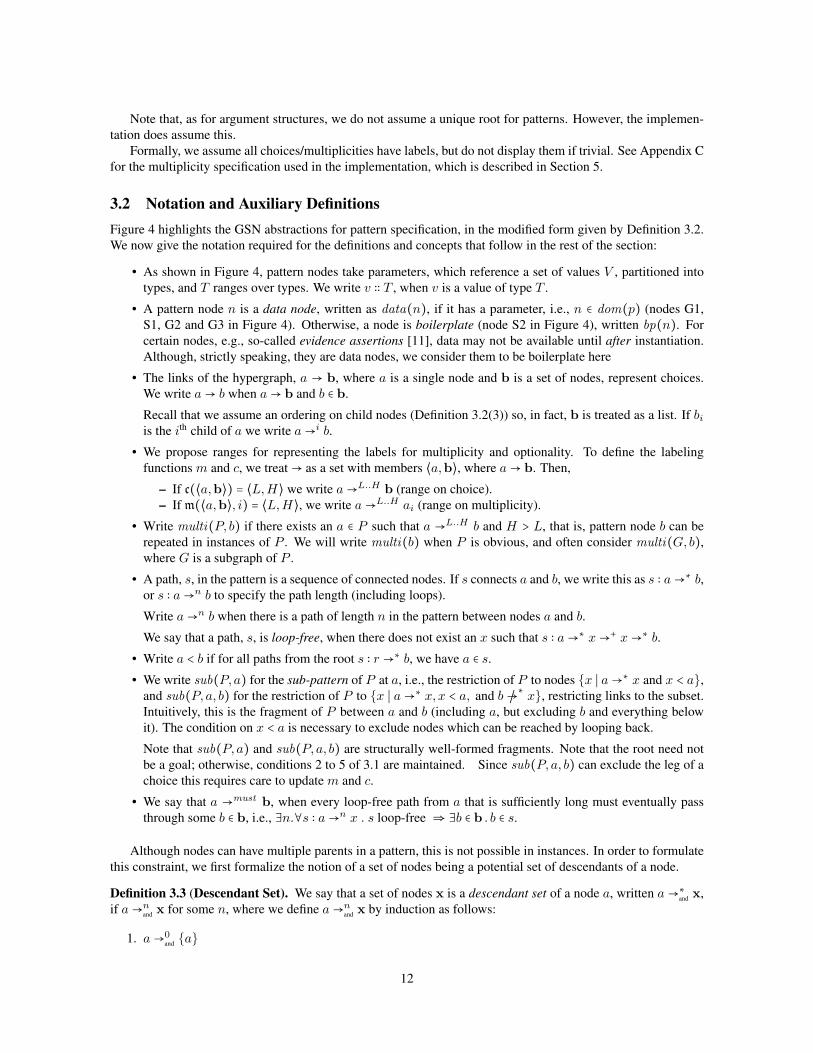
3.2 Notation and Auxiliary DefinitionsFigure 4 highlights the GSN abstractions for pattern specification, in the modified form given by Definition 3.2.
We now give the notation required for the definitions and concepts that follow in the rest of the section:
• As shown in Figure 4, pattern nodes take parameters, which reference a set of values V , partitioned into
types, and T ranges over types. We write v ∶∶ T , when v is a value of type T .
• A pattern node n is a data node, written as data(n), if it has a parameter, i.e., n ∈ dom(p) (nodes G1,
S1, G2 and G3 in Figure 4). Otherwise, a node is boilerplate (node S2 in Figure 4), written bp(n). For
certain nodes, e.g., so-called evidence assertions [11], data may not be available until after instantiation.
Although, strictly speaking, they are data nodes, we consider them to be boilerplate here
• The links of the hypergraph, a → b, where a is a single node and b is a set of nodes, represent choices.
We write a → b when a → b and b ∈ b.
Recall that we assume an ordering on child nodes (Definition 3.2(3)) so, in fact, b is treated as a list. If biis the ith child of a we write a →i b.
• We propose ranges for representing the labels for multiplicity and optionality. To define the labeling
functions m and c, we treat → as a set with members ⟨a,b⟩, where a → b. Then,
– If c(⟨a,b⟩) = ⟨L,H⟩ we write a →L..H b (range on choice).
– If m(⟨a,b⟩, i) = ⟨L,H⟩, we write a →L..H ai (range on multiplicity).
• Write multi(P, b) if there exists an a ∈ P such that a →L..H b and H > L, that is, pattern node b can be
repeated in instances of P . We will write multi(b) when P is obvious, and often consider multi(G, b),
where G is a subgraph of P .
• A path, s, in the pattern is a sequence of connected nodes. If s connects a and b, we write this as s ∶ a →∗ b,or s ∶ a →n b to specify the path length (including loops).
Write a →n b when there is a path of length n in the pattern between nodes a and b.
We say that a path, s, is loop-free, when there does not exist an x such that s ∶ a →∗ x →+ x →∗ b.
• Write a < b if for all paths from the root s ∶ r →∗ b, we have a ∈ s.
• We write sub(P, a) for the sub-pattern of P at a, i.e., the restriction of P to nodes {x ∣ a →∗ x and x < a},
and sub(P, a, b) for the restriction of P to {x ∣ a →∗ x,x < a, and b /→∗ x}, restricting links to the subset.
Intuitively, this is the fragment of P between a and b (including a, but excluding b and everything below
it). The condition on x < a is necessary to exclude nodes which can be reached by looping back.
Note that sub(P, a) and sub(P, a, b) are structurally well-formed fragments. Note that the root need not
be a goal; otherwise, conditions 2 to 5 of 3.1 are maintained. Since sub(P, a, b) can exclude the leg of a
choice this requires care to update m and c.
• We say that a →must b, when every loop-free path from a that is sufficiently long must eventually pass
through some b ∈ b, i.e., ∃n.∀s ∶ a →n x . s loop-free ⇒ ∃b ∈ b . b ∈ s.
Although nodes can have multiple parents in a pattern, this is not possible in instances. In order to formulate
this constraint, we first formalize the notion of a set of nodes being a potential set of descendants of a node.
Definition 3.3 (Descendant Set). We say that a set of nodes x is a descendant set of a node a, written a →∗and
x,
if a →nand
x for some n, where we define a →nand
x by induction as follows:
1. a →0and
{a}
12
2. a →n+1and
x if any of the following hold:
(a) a →nand
x, or
(b) If a → bi for all i, and bi →nand
xi, then a →n+1and ⋃i xi, or
(c) If a → b = {bi}i∈I (where the bi are choices) for all i, and c = ⟨L,H⟩, {bj}j∈J ⊆ b, L ≤ ∣J ∣ ≤ H ,
then, a →n+1and ⋃j∈J xj.
Intuitively, this means there is some instance argument in which a →∗ x for every x ∈ x. Note the distinction
between conjunctive a →and {b, c} and disjunctive a → {b, c}.
Next, define x →and b to mean x → b for every x ∈ x.
Definition 3.4 (Single Parent Condition). We say that a pattern satisfies the single parent condition, if whenever
a →∗and
x →and b we must have ∣x∣ = 1.
Next, we now introduce a restriction on the combination of multiplicities and boilerplate nodes. The intuition
is that multiplicities should be resolved by data, and not arbitrarily duplicated: it is only meaningful to repeat
those boilerplate nodes associated with distinctly instantiated data nodes.
Definition 3.5 (Multiplicity Condition). We say that a pattern satisfies the multiplicity condition when for all
nodes b, if multi(b), and not data(b), then there exists a c such that b →∗ c, data(c), and for all x such that
b →+ x →∗ c, not (multi(x) and bp(x)).
In other words, a multiplicity that is followed by boilerplate must eventually be followed by a data node, with
no other multiplicity in between. This has two consequences: (i) we cannot have multiplicities that do not end in
data, and (ii) two multiplicities must have intervening data.
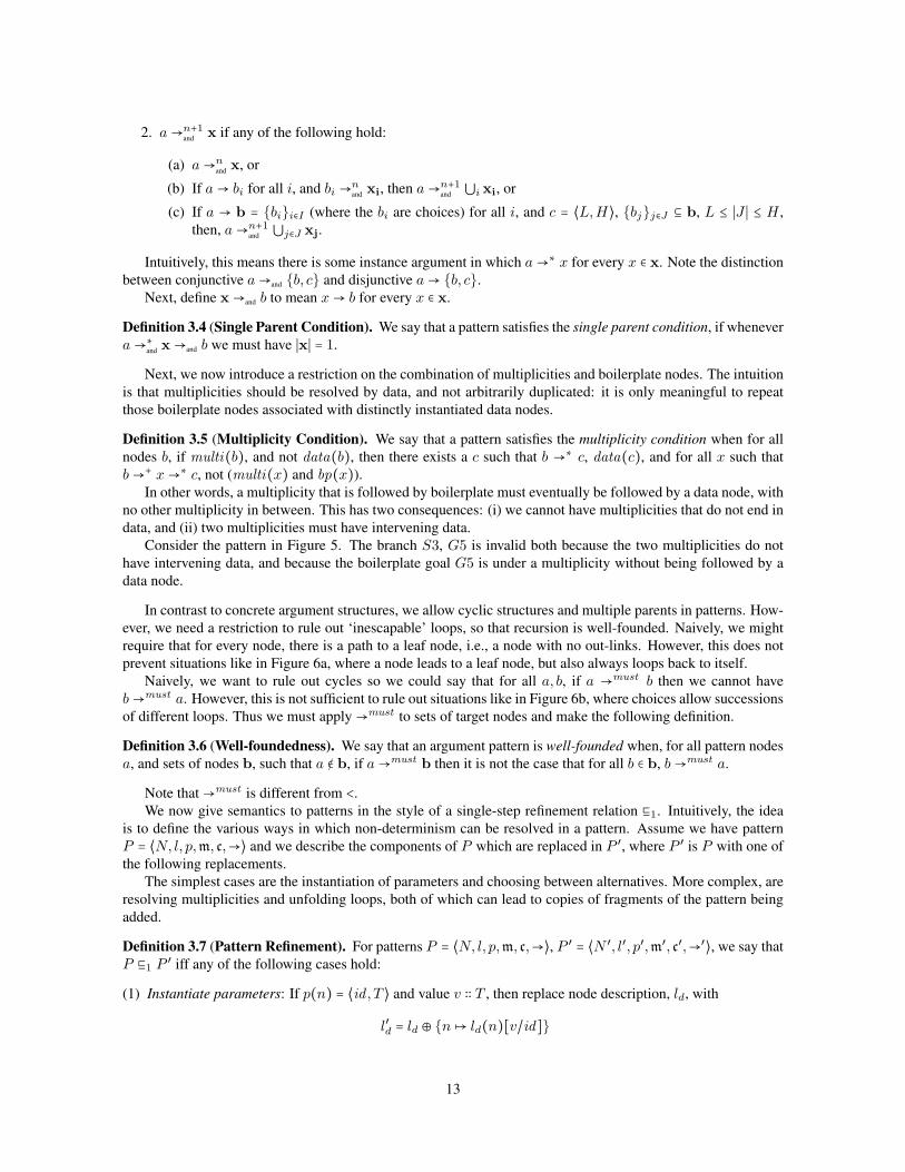
Consider the pattern in Figure 5. The branch S3, G5 is invalid both because the two multiplicities do not
have intervening data, and because the boilerplate goal G5 is under a multiplicity without being followed by a
data node.
In contrast to concrete argument structures, we allow cyclic structures and multiple parents in patterns. How-
ever, we need a restriction to rule out ‘inescapable’ loops, so that recursion is well-founded. Naively, we might
require that for every node, there is a path to a leaf node, i.e., a node with no out-links. However, this does not
prevent situations like in Figure 6a, where a node leads to a leaf node, but also always loops back to itself.
Naively, we want to rule out cycles so we could say that for all a, b, if a →must b then we cannot have
b →must a. However, this is not sufficient to rule out situations like in Figure 6b, where choices allow successions
of different loops. Thus we must apply →must to sets of target nodes and make the following definition.
Definition 3.6 (Well-foundedness). We say that an argument pattern is well-founded when, for all pattern nodes
a, and sets of nodes b, such that a ∉ b, if a →must b then it is not the case that for all b ∈ b, b →must a.
Note that →must is different from <.
We now give semantics to patterns in the style of a single-step refinement relation ⊑1. Intuitively, the idea
is to define the various ways in which non-determinism can be resolved in a pattern. Assume we have pattern
P = ⟨N, l, p,m, c,→⟩ and we describe the components of P which are replaced in P ′, where P ′ is P with one of
the following replacements.
The simplest cases are the instantiation of parameters and choosing between alternatives. More complex, are
resolving multiplicities and unfolding loops, both of which can lead to copies of fragments of the pattern being
added.
Definition 3.7 (Pattern Refinement). For patterns P = ⟨N, l, p,m, c,→⟩, P ′ = ⟨N ′, l′, p′,m′, c′,→′⟩, we say that
P ⊑1 P ′ iff any of the following cases hold:
(1) Instantiate parameters: If p(n) = ⟨id , T ⟩ and value v ∶∶ T , then replace node description, ld, with
l′d = ld ⊕ {n ↦ ld(n)[v/id]}
13
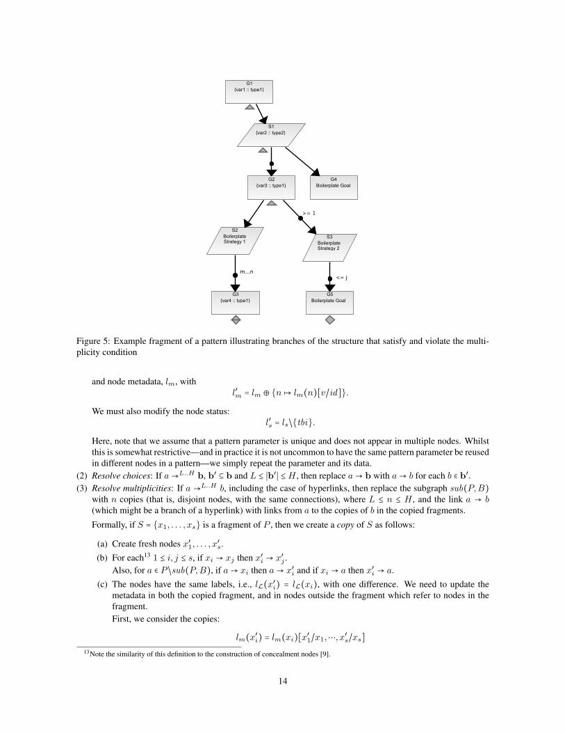
Figure 5: Example fragment of a pattern illustrating branches of the structure that satisfy and violate the multi-
plicity condition
and node metadata, lm, with
l′m = lm ⊕ {n ↦ lm(n)[v/id]}.
We must also modify the node status:
l′s = ls/{tbi}.
Here, note that we assume that a pattern parameter is unique and does not appear in multiple nodes. Whilst
this is somewhat restrictive—and in practice it is not uncommon to have the same pattern parameter be reused
in different nodes in a pattern—we simply repeat the parameter and its data.
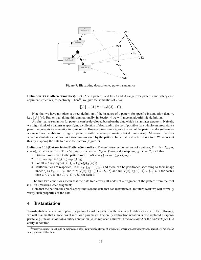
(2) Resolve choices: If a →L..H b, b′ ⊆ b and L ≤ ∣b′∣ ≤H , then replace a → b with a → b for each b ∈ b′.(3) Resolve multiplicities: If a →L..H b, including the case of hyperlinks, then replace the subgraph sub(P,B)
with n copies (that is, disjoint nodes, with the same connections), where L ≤ n ≤ H , and the link a → b(which might be a branch of a hyperlink) with links from a to the copies of b in the copied fragments.
Formally, if S = {x1, . . . , xs} is a fragment of P , then we create a copy of S as follows:
(a) Create fresh nodes x′1, . . . , x′s.
(b) For each13 1 ≤ i, j ≤ s, if xi → xj then x′i → x′j .
Also, for a ∈ P /sub(P,B), if a → xi then a → x′i and if xi → a then x′i → a.
(c) The nodes have the same labels, i.e., lL(x′i) = lL(xi), with one difference. We need to update the
metadata in both the copied fragment, and in nodes outside the fragment which refer to nodes in the
fragment.
First, we consider the copies:
lm(x′i) = lm(xi)[x′
1/x1,⋯, x′s/xs]
13Note the similarity of this definition to the construction of concealment nodes [9].
14

(a) Example of an invalid loop
(b) Another example of an invalid loop
Figure 6: Example pattern fragments showing incorrect usage of the loop construct
That is, replace all occurrences of nodes from the copied set in the metadata. This is because metadata
can be used to make self-references.
Next, nodes which are outside the n copies of S also need to be modified.
Let xi,j denote the ith node of the jth copy. Then, for a ∈ P /sub(P,B),
lm(a) = ⋃1≤j≤s
lm(a)[x′1,j/x1,j ,⋯, x′s,j/xs,j]
In other words, if a node outside the copied fragment refers to a node within that fragment, then for each
copy of that node, it needs a separate attribute referring to the copied node.
(4) Unfold loops: If a →∗ b, b → a, and a < b (all paths to b must first pass through a), then let S be the sub-
pattern of P at a, sub(P, a). We create a copy of S and replace the link from b to a with a link from b to the
copy of S (i.e., we sequentially compose the two fragments).
Then,
P ⊑ P ′ iff P ⊑∗1 P ′
A pattern instance is then the result of resolving all the non-determinism.
Note that refinement is clearly not confluent (since parameters can be instantiated in different ways). More-
over, the order in which we refine a pattern is significant. In the implementation, these steps can be combined.
For example, although resolution of multiplicity should formally take place before parameter instantiation, mul-
tiplicity is typically resolved as paramaters are instantiated, that is, the number of values used to instantiate
parameters determines the multiplicity of node instances. Similarly, if a choice is within a loop, different results
are obtained depending on whether the choice is resolved before or after unfolding the loop.
We will define pattern semantics in terms of refinement to arguments. Formally, however, a pattern refines to
another pattern, so we need to set up a correspondence between concrete patterns and arguments structures. We
define this as an embedding from the set of argument structures into the set of patterns.
Definition 3.8 (Pattern Embedding). An embedding E of an argument structure into a pattern is given as
E(⟨N, l,→⟩) = ⟨N, l, p,m, c,→′⟩ where p = ∅, the labeling functions m and c always return 1..1, and hyperedges
have a single target, i.e., for all nodes a ∈ N , →′ (a) = {→ (a)}.
We can now define the semantics of a pattern as the set of arguments equivalent to the refinements of the
pattern.
15
V1
V21
V31 V32
V22
V33
Figure 7: Illustrating data-oriented pattern semantics
Definition 3.9 (Pattern Semantics). Let P be a pattern, and let C and A range over patterns and safety case
argument structures, respectively. Then14, we give the semantics of P as
[[P ]] = {A ∣ P ⊑ C,E(A) = C}
Note that we have not given a direct definition of the instance of a pattern for specific instantiation data, τ ,
i.e., [[P ]](τ). Rather than doing this denotationally, in Section 4 we will give an algorithmic definition.
An alternative semantics for patterns can be developed based on the data which instantiates a pattern. Naively,
we might think of a pattern as specifying a collection of data, and so the set of possible data which can instantiate a
pattern represents its semantics in some sense. However, we cannot ignore the text of the pattern nodes (otherwise
we would not be able to distinguish patterns with the same parameters but different text). Moreover, the data
which instantiates a pattern has a structure imposed by the pattern. In fact, it is structured as a tree. We represent
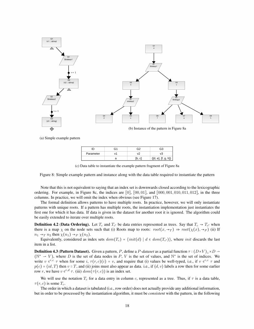
this by mapping the data tree into the pattern (Figure 7).
Definition 3.10 (Data-oriented Pattern Semantics). The data-oriented semantics of a pattern, P = ⟨NP , l, p,m,c,→P ⟩, is the set of trees, T = ⟨NT ,→T , v⟩, where v ∶ NT → Value and a mapping, χ ∶ T → P , such that
1. Data tree roots map to the pattern root: root(x,→T ) ⇒ root(χ(x),→P )2. If n1 →T n2 then χ(n1) →P χ(n2)3. For all n ∈ NT , type(v(n)) = type(p(χ(n)))4. Multiplicities are respected: if x →T {y1, . . . , yj} and these can be partitioned according to their image
under χ as Y1, . . . , Yk, and if c(⟨χ(x), χ(Y )⟩) = ⟨L,H⟩ and m(⟨χ(x), χ(Y )⟩, i) = ⟨Li,Hi⟩ for each ithen L ≤ k ≤H and Li ≤ ∣Yi∣ ≤Hi for each i.
The first two conditions mean that the data tree covers all nodes of a fragment of the pattern from the root
(i.e., an upwards-closed fragment).
Note that the pattern thus places constraints on the data that can instantiate it. In future work we will formally
verify such properties of the data.
4 InstantiationTo instantiate a pattern, we replace the parameters of the pattern with the concrete data elements. In the following,
we will assume that a node has at most one parameter. The entity abstraction notation is also replaced as appro-
priate, e.g., the uninstantiated entity annotation (△) is replaced either with the developed or the undeveloped (◇)
entity annotation.
14Strictly speaking, this should be defined as a set of equivalence classes of arguments, where we abstract over node identifiers, but we can
safely gloss over that here.
16
We use sets of values to instantiate parameters in patterns to create instance arguments. Roughly speaking,
data can be given as a mapping from the parameters of data nodes to lists of values. Now, we formalize the
concept of a pattern dataset, define a notion of compliance between data and a pattern, and specify a generic
instantiation algorithm.
Definition 3.9 semantically formalizes the notion of a fully instantiated pattern. We now give a corresponding
algorithmic definition, but extend it to give a notion of partial instantiation and identify conditions under which
a partial instance is, in fact, full.
We adopt a liberal notion of pattern instance and do not require a dataset to instantiate all the parameters
(though with the restrictions specified below in Definition 4.4). Hence, uninstantiated nodes do not appear in
the resulting instance15. Moreover, since the instance is built up by adding fragments consisting of instantiated
data node plus the boilerplate between that node and the previously added node (see line 25, Algorithm 2), it
will never be the case that we add a choice between boilerplate nodes to the instance, and so the instance is
well-formed.
4.1 Datasets and TablesSince a pattern is a graph there can be multiple ways to navigate through it (due to recursion and nodes with
multiple parents) and, therefore, connect the instance nodes. To make clear where an instantiated node should
be connected, we need to associate each ‘instantiation path’ through the pattern with a join point (or simply
join), indicating where a “pass” through the pattern begins. A join uniquely indicates the location at which an
instantiated branch of the argument structure is to be appended. In practice, join points can be omitted if the
location can be unambiguously determined, but the algorithm given here assumes they are given for all rows but
the first.
Joins comprise data nodes, paired with values, which together uniquely specify an instance node. See Fig-
ure 17b, p. 31. Data will typically be represented in tabular form where we label columns by data nodes, d, and
rows by ⟨d, v⟩ pairs, i.e., joins. We also allow rows to be labeled with a blank entry, in the case of the root. Entries
in the table are represented as indexed lists of values, indicating multiple branches attached to the same point
(alternatively, as explained below, these branches can be given on separate rows—the verbose representation),
and corresponding to branches given earlier in the row.
Due to multiplicities in patterns, nodes can be repeatedly instantiated. This is indicated in a dataset by
giving multiple values for a single entry (the row corresponding to the pass through the pattern, and the column
corresponding to the pattern node). If, however, there is another multiplicity in the pattern for a subsequent node,
the possibility of multiple intances below is compounded. This is indicated by giving a list of lists of values in
the column. Hence, entries for a dataset actually are trees of values in order to make clear which instance nodes
link to which parent branch.
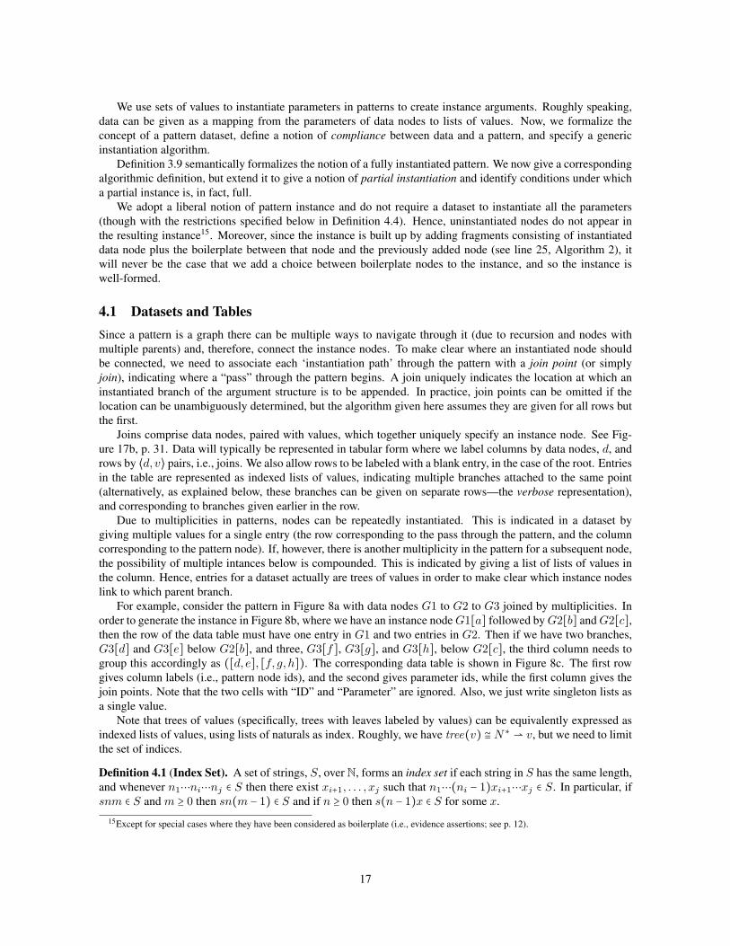
For example, consider the pattern in Figure 8a with data nodes G1 to G2 to G3 joined by multiplicities. In
order to generate the instance in Figure 8b, where we have an instance node G1[a] followed by G2[b] and G2[c],then the row of the data table must have one entry in G1 and two entries in G2. Then if we have two branches,
G3[d] and G3[e] below G2[b], and three, G3[f], G3[g], and G3[h], below G2[c], the third column needs to
group this accordingly as ([d, e], [f, g, h]). The corresponding data table is shown in Figure 8c. The first row
gives column labels (i.e., pattern node ids), and the second gives parameter ids, while the first column gives the
join points. Note that the two cells with “ID” and “Parameter” are ignored. Also, we just write singleton lists as
a single value.
Note that trees of values (specifically, trees with leaves labeled by values) can be equivalently expressed as
indexed lists of values, using lists of naturals as index. Roughly, we have tree(v) ≅ N∗ ⇀ v, but we need to limit
the set of indices.
Definition 4.1 (Index Set). A set of strings, S, over N, forms an index set if each string in S has the same length,
and whenever n1⋯ni⋯nj ∈ S then there exist xi+1, . . . , xj such that n1⋯(ni − 1)xi+1⋯xj ∈ S. In particular, if
snm ∈ S and m ≥ 0 then sn(m − 1) ∈ S and if n ≥ 0 then s(n − 1)x ∈ S for some x.
15Except for special cases where they have been considered as boilerplate (i.e., evidence assertions; see p. 12).
17
(a) Simple example pattern
(b) Instance of the pattern in Figure 8a
ID G1 G2 G3Parameter v1 v2 v3
a [b, c] ([d, e], [f, g, h])
(c) Data table to instantiate the example pattern fragment of Figure 8a
Figure 8: Simple example pattern and instance along with the data table required to instantiate the pattern
Note that this is not equivalent to saying that an index set is downwards closed according to the lexicographic
ordering. For example, in Figure 8c, the indices are [0], [00,01], and [000,001,010,011,012], in the three
columns. In practice, we will omit the index when obvious (see Figure 17).
The formal definition allows patterns to have multiple roots. In practice, however, we will only instantiate
patterns with unique roots. If a pattern has multiple roots, the instantiation implementation just instantiates the
first one for which it has data. If data is given in the dataset for another root it is ignored. The algorithm could
be easily extended to iterate over multiple roots.
Definition 4.2 (Data Ordering). Let Tc and Tc′ be data entries represented as trees. Say that Tc ↝ Tc′ when
there is a map χ on the node sets such that (i) Roots map to roots: root(x,→T ) ⇒ root(χ(x),→P ) (ii) If
n1 →T n2 then χ(n1) →P χ(n2).
Equivalently, considered as index sets dom(Tc) = {init(d) ∣ d ∈ dom(Tc′)}, where init discards the last
item in a list.
Definition 4.3 (Pattern Dataset). Given a pattern, P , define a P -dataset as a partial function τ ∶ (D×V )�×D ⇀(N∗ ⇀ V ), where D is the set of data nodes in P , V is the set of values, and N
∗ is the set of indices. We
write v ∈r,c τ when for some i, τ(r, c)(i) = v, and require that (i) values be well-typed, i.e., if v ∈r,c τ and
p(c) = ⟨id , T ⟩ then v ∶∶ T , and (ii) joins must also appear as data. i.e., if ⟨d, v⟩ labels a row then for some earlier
row r, we have v ∈r,d τ . (iii) dom(τ(r, c)) is an index set.
We will use the notation Tc for a data entry in column c, represented as a tree. Thus, if τ is a data table,
τ(r, c) is some Tc.
The order in which a dataset is tabulated (i.e., row order) does not actually provide any additional information,
but in order to be processed by the instantiation algorithm, it must be consistent with the pattern, in the following
18
sense: the order of columns must respect node order,16 <, i.e., if a < b then the corresponding columns are in that
order; also, for each row ⟨d, v⟩, we require that v appears in column d in a preceding row.
In the following, we will assume that a consistent order has been chosen for a dataset, and refer to it as a
P -table (see Figure 17b for an example).
Definition 4.4 (Data Compliance). For pattern P and P -table τ , we say that the table complies with the pattern,
τ ⊧ P , if the following two conditions hold:
(i) τ meets the cardinality constraints of P , i.e., ∀c . L ≤ ∣τ(( , ), c)∣ ≤ H , where ⟨L,H⟩ = m(i, c′), where
c′ →i c.(ii) τ is upwards-closed, i.e., for each r labeled ⟨d, ⟩ and column c, if Tv ∈r,c τ then there exist c′, Tv′ such
that c ≤1 c′ ≤ d (i.e., c′ is the parent of c) and Tv′ ∈r,c′
τ , and Tv′ ↝ Tv .
In other words, if a row of a data table instantiates a node in the pattern, it must also instantiate a chain of
parent nodes (not necessarily all parents) back to the join of that row. Note that the ordering, c ≤ c′ ≤ d, is
in the pattern, not the columns.
Similarly, if the row is labeled blank, then there exist c′, v′ such that c ≤1 c′ ≤ root and v′ ∈r,c′
τ .
The intuition behind upwards closure is that, in line with our notion of partial instantiation, although not all
nodes need be instantiated, we do require that parameters can be instantiated in order from the root. A row,
therefore, consists of the data that instantiates an upward-closed fragment of the pattern, following the paths of
the fragment up until its join (see Figure 18 for an example).
The dual notion of downwards-closure is used to specify when a dataset fully instantiates a pattern.
Definition 4.5 (Full Dataset). We say that a dataset is full if it is downwards-closed, that is, for each row, if
there is a va in column a and a → b in the pattern, with choice-multiplicity ⟨L,H⟩, then there must be separate
vb1 , . . . , vbn in the table, where L ≤ n ≤ H , such that for each i, Ta ↝ Tbi .
Moreover, if bi < a then the vbi must be in the same row as the va, and if a < bi (i.e., a loops back to bi), the
vbi must be in a subsequent row.
We can actually relax the requirement that values for non-looped data nodes are in the same row. If they are
in a subsequent row, then that row must have a join point corresponding to the parent instance data node. Note
also that if a dataset is upwards-closed then the condition that Ta ↝ Tbi will follow.
The multiplicity condition says that multiplicities must be resolved by data, ie. a multi-node cannot be
followed by boilerplate alone. Similarly, we could additionally require that choices followed by boilerplate must
be eventually followed by data, so that choices are resolved by data. This is not required by the algorithm,
however, which will omit unresolved choices.
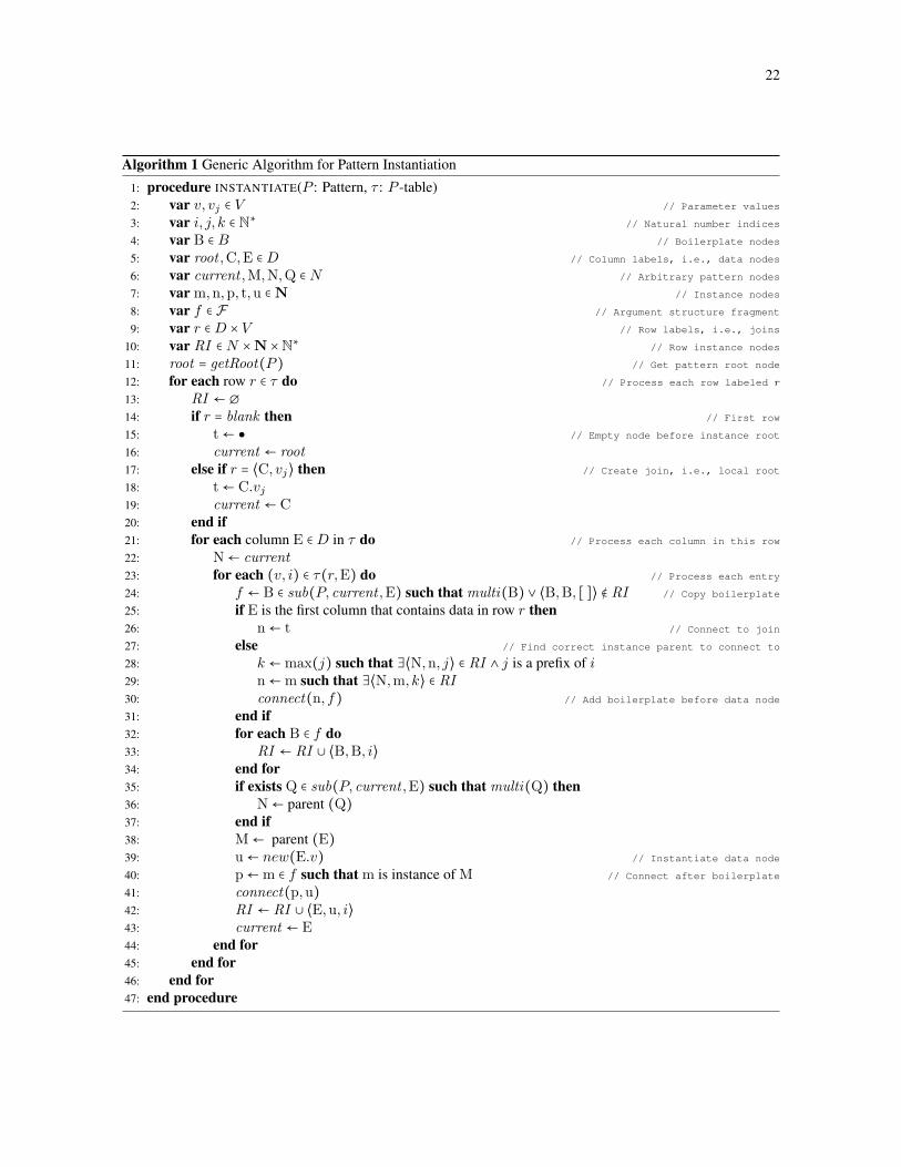
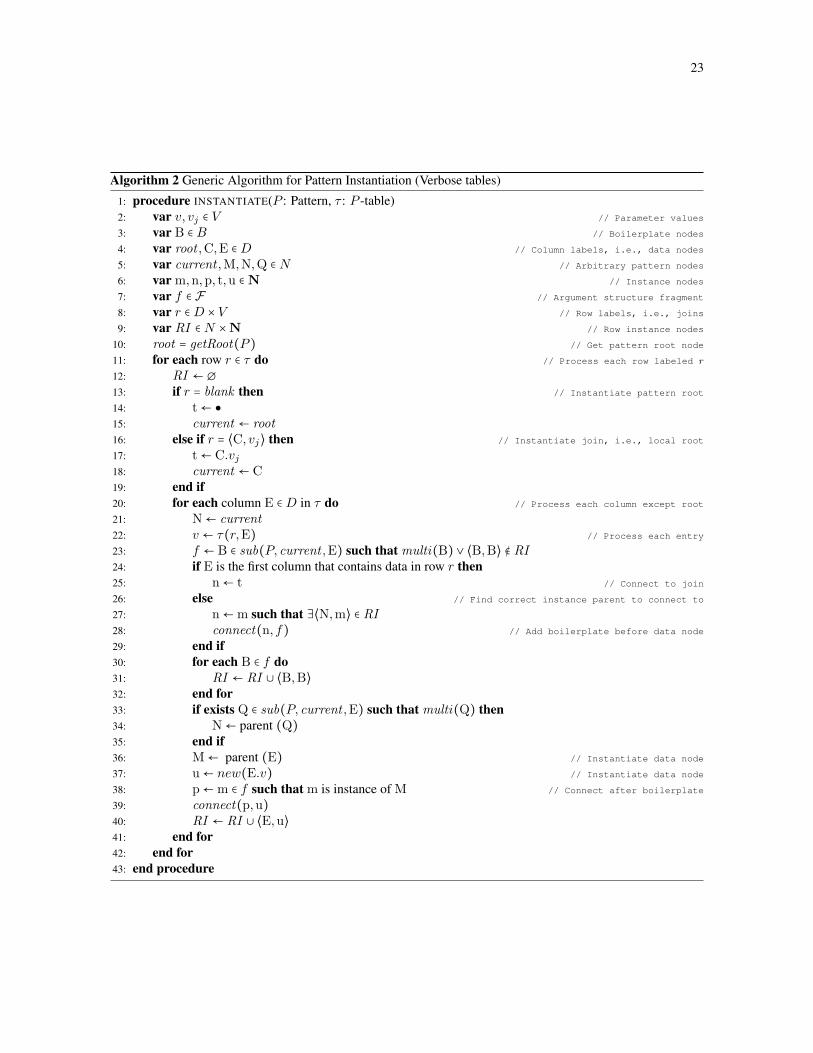
4.2 AlgorithmWe now specify instantiate(P, τ), the generic procedure for pattern instantiation. We give two versions of the
algorithm. Algorithm 1 uses the (concise) form of data table described in the theory above, whereas Algorithm 2
uses a verbose data structure, in which rather than have multiple entries for a given row/column, the data is
“unfolded” over multiple rows. This is, in fact, the form of the algorithm which is currently implemented in
AdvoCATE. In addition, Figure 9 gives a higher-level specification with additional syntactic sugar (from [1]),
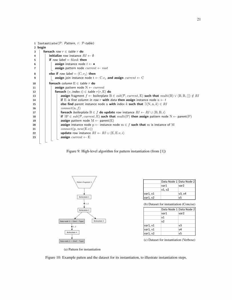
based on the concise data structure.
The input is a pattern P = ⟨N, l, p,m, c,→⟩ and P -table τ , and output is an instance ⟨N, l,→⟩ created via
side-effect. P is accessed via its root (using getRoot), by accessing and instantiating specific pattern nodes, C.v(copying over the metadata without analysis; it’s not accessed directly), by determining the parent of a given
node, and by determining the multiplicity of a link (via multi, which checks m and c); and by constructing
sub-patterns (via sub). The instance is created via new (creating nodes with metadata) and connect (creating
links).
Note that we do not describe the low-level format of the pattern and instance in the algorithm, and just
assume that we have some representation where we can create nodes, locate node instances (by pattern node C
16See definition of < on p. 12.
19
and parameter value v), connect at a node, determine multiplicity of a node in a pattern, create a sub-pattern, and
locate a parent. The algorithm thus does not explicitly address the creation of the labeling functions.
• Recall that N is the subset of pattern nodes, in which D is the set of data nodes whose parameters take
values v ∈ V , and where Droot ∈ D is the root data node. Now, we can define the set B = N ∖D, the set
of boilerplate nodes.
• Let N be the set of identifiers to be assigned to instance nodes. We designate a special “empty” instance
node, ●, which is used at the start of the instantiation.
We write new(D.v), to create a new instance node, given by instantiating data node D with value v, and
add it to the instance. When a boilerplate node B is instantiated, then we reference its instance simply as
B.
• We use the variable join ∈ D × V to refer to join points, so that join = ⟨d, v⟩ and D × V ⊆ N .
• For the pattern data set τ , we label columns as D and rows as (D × V )�, since a row label can be either a
join point or a blank.
• Recall also, that values v can be either a single datum or a list. We assume that values are indexed by I ,
the set of indices. We will use a set RI = {⟨N,N.v, I⟩}, of row instance nodes.
• Finally, let F be the set of argument structure fragments. To connect a fragment f ∈ F , we use a function
connect(m,f), which sequentially composes f with the current instance fragment at instance node m. In
the algorithm, f will be either a fragment of boilerplate nodes or an instantiated data node D.v. In the case
where m = ●, we initiate the instance with f .
To instantiate a pattern P , given its P -table τ , we process each row to create a row instance fragment, which
is effectively the assignment of parameter values in the table to the corresponding data nodes in the pattern. We
construct the row instance based on the ordering of the data nodes in the columns. For each value we add not
just the instantiation of the appropriate data node, but also any boilerplate between that node and the preceding
data node. We record information about the fragment of the row instance which has already been constructed
as RI ∈ N × N × N∗, where N , N, and N
∗ are the sets of pattern nodes, instance nodes and natural number
indices respectively. Multiplicities, especially, require careful consideration: multiple values in the P -table lead
to multiple instances of a data node, but we only repeat those boilerplate nodes which appear after a multiplicity
(see Figure 18 for an example). We use instance indices to connect nodes to the correct parent when there are
such multiples. We will use upper case variables for pattern nodes and lower case for instance nodes. At any
point in the algorithm we identify the current pattern node as current , and the pattern root as root .Since data table entries can be lists of values, we need to know which nodes of the pattern have already been
instantiated; we also need to know the correspondence between a set of newly instantiated nodes and the kth
instance of a pattern node in a fragment to which it should be connected. Thus, whenever we add a node to the
instance, we track the nodes that have been created through the set of row instance nodes RI , appending to RIthe triple ⟨N,N.v,N∗⟩ of pattern node, instance node and value index.
RI serves two purposes, therefore: recording which boilerplate nodes have already been added (line 24,
Algorithm 1) and determining the correct instance parent to connect to (lines 28, 29).
4.3 CorrectnessWe want to show that the algorithm produces correct instantiations. In order to define partial instantiations, we
first define sub-arguments.
Definition 4.6. Let S1 = ⟨N1, l1,→1⟩ and S2 = ⟨N2, l2,→2⟩ be safety arguments. We say that S1 is a sub-argument of S2 if N1 ⊆ N2, →1=→2↾N1 , l1 = l2 ↾N1 , and if n1 ∈ S1, n2 ∈ S2, and n2 →2 n1, then n2 ∈ N1.
The final condition states that the nodes of S1 are upwards closed within S2. Hence S1 and S2 share roots.
Now recall that [[P ]] denotes the set of (full) instantiations of pattern P . We will show that a partial instantiation
is, in fact, a sub-argument of a full instantiation, and so write sub[[P ]] for the set of partial instantiations of P .
A sub-argument is structurally well-formed. (see p. 11). A partial instantiation is also equivalent to the instance
given by a set of upwards-closed paths through a pattern.
We now give the correctness property of the instantiation algorithm and sketch its proof. We reason at a high
level so do not distinguish between verbose and concise versions of the algorithm.
20
21
1 Instantiate(P: Pattern, τ : P-table)2 begin3 foreach row r ∈ table τ do4 initialize row instance RI ← ∅5 if row label = blank then6 assign instance node t ← •7 assign pattern node current ← root
8 else if row label = 〈C, vj〉 then9 assign join instance node t ← C.vj and assign current ← C
10 foreach column E ∈ table τ do11 assign pattern node N ← current12 foreach (v, index i) ∈ table τ(r,E) do13 assign fragment f ← boilerplate B ∈ sub(P, current ,E) such that multi(B) ∨ 〈B,B, [ ]〉 /∈ RI14 if E is first column in row r with data then assign instance node n ← t15 else find parent instance node n with index k such that ∃〈N, n, k〉 ∈ RI16 connect(n, f)17 foreach boilerplate B ∈ f do update row instance RI ← RI ∪ 〈B,B, i〉18 if ∃P ∈ sub(P, current ,E) such that multi(P) then assign pattern node N ← parent(P)19 assign pattern node M ← parent(E)20 assign instance node p ← instance node m ∈ f such that m is instance of M21 connect(p,new(E.v))22 update row instance RI ← RI ∪ 〈E,E.v, i〉23 assign current ← E
Figure 9: High-level algorithm for pattern instantiation (from [1])
(a) Pattern for instantiation
(b) Dataset for instantiation (Concise)
(c) Dataset for instantiation (Verbose)
Figure 10: Example patten and the dataset for its instantiation, to illustrate instantiation steps.
22
Algorithm 1 Generic Algorithm for Pattern Instantiation
1: procedure INSTANTIATE(P : Pattern, τ : P -table)
2: var v, vj ∈ V // Parameter values
3: var i, j, k ∈ N∗ // Natural number indices
4: var B ∈ B // Boilerplate nodes
5: var root ,C,E ∈ D // Column labels, i.e., data nodes
6: var current ,M,N,Q ∈ N // Arbitrary pattern nodes
7: var m,n,p, t,u ∈ N // Instance nodes
8: var f ∈ F // Argument structure fragment
9: var r ∈ D × V // Row labels, i.e., joins
10: var RI ∈ N ×N ×N∗
// Row instance nodes
11: root = getRoot(P ) // Get pattern root node
12: for each row r ∈ τ do // Process each row labeled r
13: RI ← ∅14: if r = blank then // First row
15: t ← ● // Empty node before instance root
16: current ← root17: else if r = ⟨C, vj⟩ then // Create join, i.e., local root
18: t ← C.vj19: current ← C20: end if21: for each column E ∈ D in τ do // Process each column in this row
22: N ← current23: for each (v, i) ∈ τ(r,E) do // Process each entry
24: f ← B ∈ sub(P, current ,E) such that multi(B) ∨ ⟨B,B, [ ]⟩ ∉ RI // Copy boilerplate
25: if E is the first column that contains data in row r then26: n ← t // Connect to join
27: else // Find correct instance parent to connect to
28: k ←max(j) such that ∃⟨N,n, j⟩ ∈ RI ∧ j is a prefix of i29: n ←m such that ∃⟨N,m, k⟩ ∈ RI30: connect(n, f) // Add boilerplate before data node
31: end if32: for each B ∈ f do33: RI ← RI ∪ ⟨B,B, i⟩34: end for35: if exists Q ∈ sub(P, current ,E) such that multi(Q) then36: N ← parent (Q)37: end if38: M ← parent (E)39: u ← new(E.v) // Instantiate data node
40: p ←m ∈ f such that m is instance of M // Connect after boilerplate
41: connect(p,u)42: RI ← RI ∪ ⟨E,u, i⟩43: current ← E44: end for45: end for46: end for47: end procedure
23
Algorithm 2 Generic Algorithm for Pattern Instantiation (Verbose tables)
1: procedure INSTANTIATE(P : Pattern, τ : P -table)
2: var v, vj ∈ V // Parameter values
3: var B ∈ B // Boilerplate nodes
4: var root ,C,E ∈ D // Column labels, i.e., data nodes
5: var current ,M,N,Q ∈ N // Arbitrary pattern nodes
6: var m,n,p, t,u ∈ N // Instance nodes
7: var f ∈ F // Argument structure fragment
8: var r ∈ D × V // Row labels, i.e., joins
9: var RI ∈ N ×N // Row instance nodes
10: root = getRoot(P ) // Get pattern root node
11: for each row r ∈ τ do // Process each row labeled r
12: RI ← ∅13: if r = blank then // Instantiate pattern root
14: t ← ●15: current ← root16: else if r = ⟨C, vj⟩ then // Instantiate join, i.e., local root
17: t ← C.vj18: current ← C19: end if20: for each column E ∈ D in τ do // Process each column except root
21: N ← current22: v ← τ(r,E) // Process each entry
23: f ← B ∈ sub(P, current ,E) such that multi(B) ∨ ⟨B,B⟩ ∉ RI24: if E is the first column that contains data in row r then25: n ← t // Connect to join
26: else // Find correct instance parent to connect to
27: n ←m such that ∃⟨N,m⟩ ∈ RI28: connect(n, f) // Add boilerplate before data node
29: end if30: for each B ∈ f do31: RI ← RI ∪ ⟨B,B⟩32: end for33: if exists Q ∈ sub(P, current ,E) such that multi(Q) then34: N ← parent (Q)35: end if36: M ← parent (E) // Instantiate data node
37: u ← new(E.v) // Instantiate data node
38: p ←m ∈ f such that m is instance of M // Connect after boilerplate
39: connect(p,u)40: RI ← RI ∪ ⟨E,u⟩41: end for42: end for43: end procedure

(a) Instantiation: Step 1
(b) Instantiation: Step 2
(c) Instantiation: Step 3 (d) Instantiation: Step 4
Figure 11: Steps in the instantiation of the example pattern in Figure 10a using the dataset of Figure 10c.
Theorem 1 (Correctness of Instantiation). If P is a well-founded pattern that satisfies the multiplicity and
single parent conditions, and dataset τ ⊧ P , then
1. instantiate(P, τ) ∈ sub[[P ]].
2. Moreover, if τ is full, then instantiate(P, τ) ∈ [[P ]].
Proof. (Sketch) The full proof consists of three nested inductions over rows, columns, and data, showing that
at each point the created instance is valid. Here we will just induct over rows and, for the step case, consider a
representative row in concise form (Figure 10b; also given in verbose form in Figure 10c) instantiating a path
through a representative pattern (Figure 10a), we show that the partial instance formed by extending the current
fragment with the nodes resulting from this row is always a valid sub-argument.
First, note that a row in the dataset corresponds to a slice (upwards closed back to a join) through the pattern.
By Definition 4.3, the path given by the data contains no loops. In general, each link in the pattern represents
a choice. In the pattern here (Figure 10a), without loss of generality, we only show those links giving the paths
through the pattern corresponding to the data in this particular dataset (Figures 10c and 10b); i.e., we do not show
any loops or choices (since instantiation of a pattern is equivalent to instantiating the pattern sliced by the data
set. We show the most general case, with arbitrary boilerplate between each data node.
24
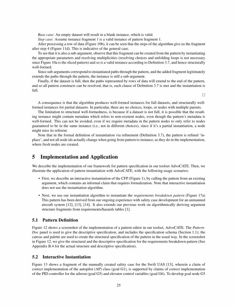
Base case: An empty dataset will result in a blank instance, which is valid.
Step case: Assume instance fragment 1 is a valid instance of pattern fragment 1.
After processing a row of data (Figure 10b), it can be seen that the steps of the algorithm give us the fragment
after step 4 (Figure 11d). This is indicative of the general case.
To see that it is also a sub-argument, observe that this fragment can be created from the pattern by instantiating
the appropriate parameters and resolving multiplicities (resolving choices and unfolding loops is not necessary
since Figure 10a is the sliced pattern) and so is a valid instance according to Definition 3.7, and hence structurally
well-formed.
Since sub-arguments correspond to instantiated paths through the pattern, and the added fragment legitimately
extends the paths through the pattern, the instance is still a sub-argument.
Finally, if the dataset is full, then the paths represented by rows of data will extend to the end of the pattern,
and so all pattern constructs can be resolved, that is, each clause of Definition 3.7 is met and the instantiation is
full.
A consequence is that the algorithm produces well-formed instances for full datasets, and structurally well-
formed instances for partial datasets. In particular, there are no choices, loops, or nodes with multiple parents.
The limitation to structural well-formedness, is because if a dataset is not full, it is possible that the result-
ing instance might contain metadata which refers to non-existent nodes, even though the pattern’s metadata is
well-formed. This can not be avoided, even if we require metadata in the pattern nodes to only refer to nodes
guaranteed to be in the same instance (i.e., not in different choices), since if it’s a partial instantiation, a node
might miss its referent.
Note that in the formal definition of instantiation via refinement (Definition 3.7), the pattern is refined ‘in-
place’, and not all node ids actually change when going from pattern to instance, as they do in the implementation,
where fresh nodes are created.
5 Implementation and ApplicationWe describe the implementation of our framework for pattern specification in our toolset AdvoCATE. Then, we
illustrate the application of pattern instantiation with AdvoCATE, with the following usage scenarios:
• First, we describe an interactive instantiation of the CFP (Figure 1), by calling the pattern from an existing
argument, which contains an informal claim that requires formalization. Note that interactive instantiation
does not use the instantiation algorithm.
• Next, we use our instantiation algorithm to instantiate the requirements breakdown pattern (Figure 17a)
This pattern has been derived from our ongoing experience with safety case development for an unmanned
aircraft system [12], [13], [14]. It also extends our previous work on algorithmically deriving argument
structure fragments from requirements/hazards tables [1].
5.1 Pattern DefinitionFigure 12 shows a screenshot of the implementation of a pattern editor in our toolset, AdvoCATE. The Pattern-Doc panel is used to give the descriptive specification, and includes the specification schema (Section 1.1); the
canvas and palette are used to create the structural specification of the pattern in the usual way. In the screenshot
in Figure 12, we give the structural and the descriptive specification for the requirements breakdown pattern (See
Appendix B.4 for the actual structure and descriptive specification).
5.2 Interactive InstantiationFigure 13 shows a fragment of the manually created safety case for the Swift UAS [13], wherein a claim of
correct implementation of the autopilot (AP) class (goal G1), is supported by claims of correct implementation
of the PID controller for the aileron (goal G5) and elevator control variables (goal G6). To develop goal node G5
25
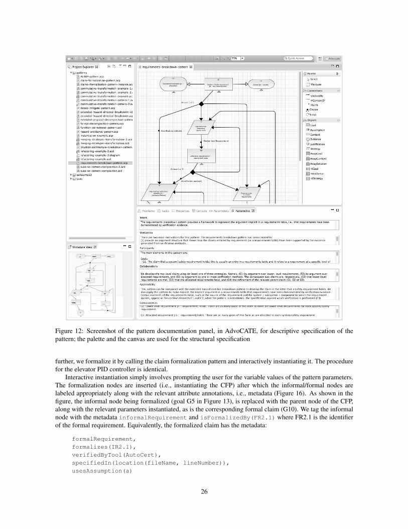
Figure 12: Screenshot of the pattern documentation panel, in AdvoCATE, for descriptive specification of the
pattern; the palette and the canvas are used for the structural specification
further, we formalize it by calling the claim formalization pattern and interactively instantiating it. The procedure
for the elevator PID controller is identical.
Interactive instantiation simply involves prompting the user for the variable values of the pattern parameters.
The formalization nodes are inserted (i.e., instantiating the CFP) after which the informal/formal nodes are
labeled appropriately along with the relevant attribute annotations, i.e., metadata (Figure 16). As shown in the
figure, the informal node being formalized (goal G5 in Figure 13), is replaced with the parent node of the CFP,
along with the relevant parameters instantiated, as is the corresponding formal claim (G10). We tag the informal
node with the metadata informalRequirement and isFormalizedBy(FR2.1) where FR2.1 is the identifier
of the formal requirement. Equivalently, the formalized claim has the metadata:
formalRequirement,
formalizes(IR2.1),
verifiedByTool(AutoCert),
specifiedIn(location(fileName, lineNumber)),
usesAssumption(a)
26
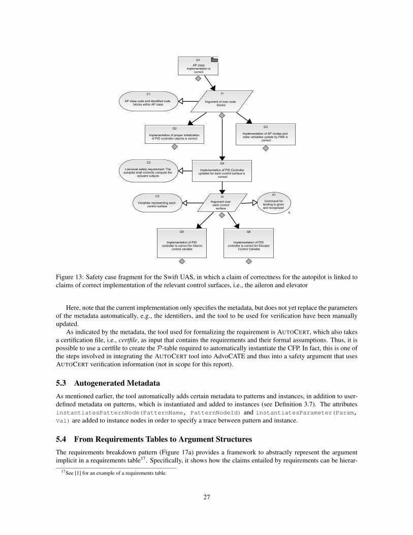
Figure 13: Safety case fragment for the Swift UAS, in which a claim of correctness for the autopilot is linked to
claims of correct implementation of the relevant control surfaces, i.e., the aileron and elevator
Here, note that the current implementation only specifies the metadata, but does not yet replace the parameters
of the metadata automatically, e.g., the identifiers, and the tool to be used for verification have been manually
updated.
As indicated by the metadata, the tool used for formalizing the requirement is AUTOCERT, which also takes
a certification file, i.e., certfile, as input that contains the requirements and their formal assumptions. Thus, it is
possible to use a certfile to create the P-table required to automatically instantiate the CFP. In fact, this is one of
the steps involved in integrating the AUTOCERT tool into AdvoCATE and thus into a safety argument that uses
AUTOCERT verification information (not in scope for this report).
5.3 Autogenerated MetadataAs mentioned earlier, the tool automatically adds certain metadata to patterns and instances, in addition to user-
defined metadata on patterns, which is instantiated and added to instances (see Definition 3.7). The attributes
instantiatesPatternNode(PatternName, PatternNodeId) and instantiatesParameter(Param,
Val) are added to instance nodes in order to specify a trace between pattern and instance.
5.4 From Requirements Tables to Argument StructuresThe requirements breakdown pattern (Figure 17a) provides a framework to abstractly represent the argument
implicit in a requirements table17. Specifically, it shows how the claims entailed by requirements can be hierar-
17See [1] for an example of a requirements table.
27
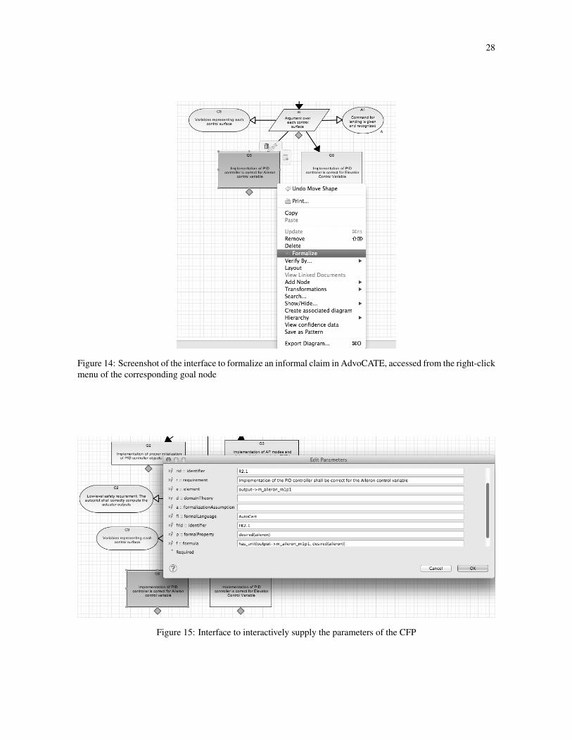
28
Figure 14: Screenshot of the interface to formalize an informal claim in AdvoCATE, accessed from the right-click
menu of the corresponding goal node
Figure 15: Interface to interactively supply the parameters of the CFP
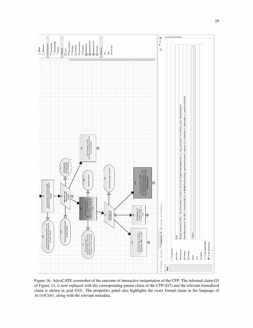
29
Figure 16: AdvoCATE screenshot of the outcome of interactive instantiation of the CFP: The informal claim G5
of Figure 13, is now replaced with the corresponding parent claim of the CFP (G7) and the relevant formalized
claim is shown in goal G10. The properties panel also highlights the exact formal claim in the language of
AUTOCERT, along with the relevant metadata.
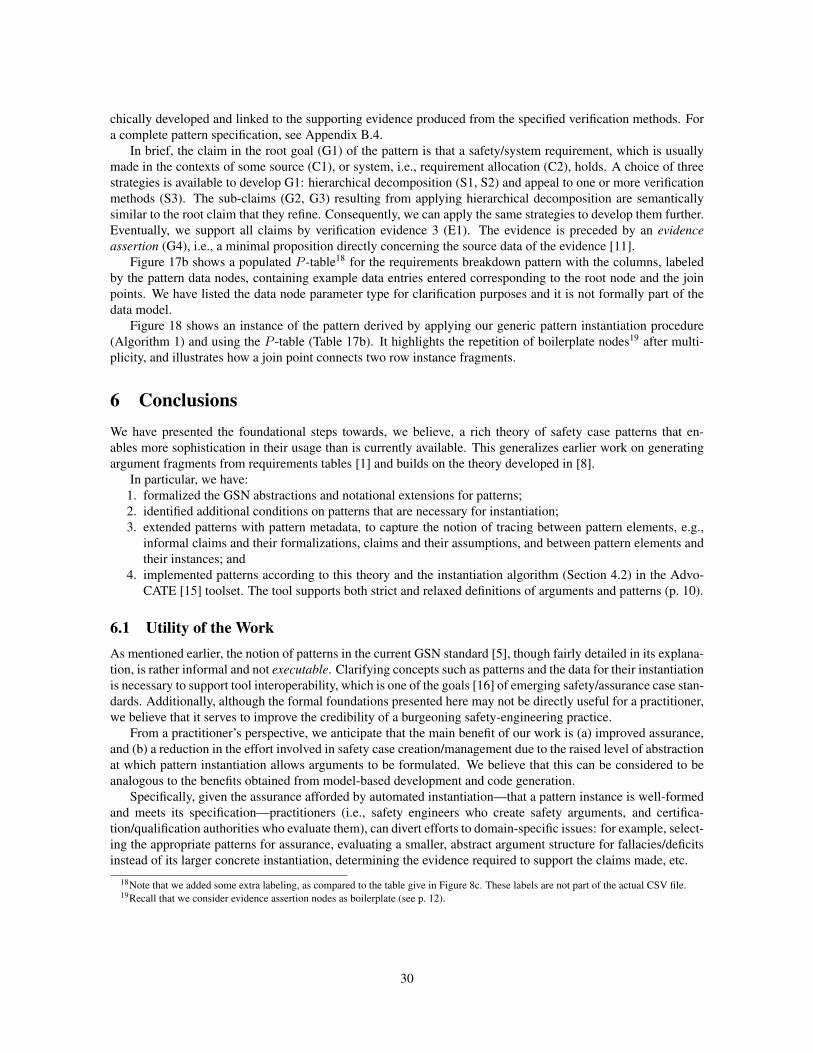
chically developed and linked to the supporting evidence produced from the specified verification methods. For
a complete pattern specification, see Appendix B.4.
In brief, the claim in the root goal (G1) of the pattern is that a safety/system requirement, which is usually
made in the contexts of some source (C1), or system, i.e., requirement allocation (C2), holds. A choice of three
strategies is available to develop G1: hierarchical decomposition (S1, S2) and appeal to one or more verification
methods (S3). The sub-claims (G2, G3) resulting from applying hierarchical decomposition are semantically
similar to the root claim that they refine. Consequently, we can apply the same strategies to develop them further.
Eventually, we support all claims by verification evidence 3 (E1). The evidence is preceded by an evidenceassertion (G4), i.e., a minimal proposition directly concerning the source data of the evidence [11].
Figure 17b shows a populated P -table18 for the requirements breakdown pattern with the columns, labeled
by the pattern data nodes, containing example data entries entered corresponding to the root node and the join
points. We have listed the data node parameter type for clarification purposes and it is not formally part of the
data model.
Figure 18 shows an instance of the pattern derived by applying our generic pattern instantiation procedure
(Algorithm 1) and using the P -table (Table 17b). It highlights the repetition of boilerplate nodes19 after multi-
plicity, and illustrates how a join point connects two row instance fragments.
6 ConclusionsWe have presented the foundational steps towards, we believe, a rich theory of safety case patterns that en-
ables more sophistication in their usage than is currently available. This generalizes earlier work on generating
argument fragments from requirements tables [1] and builds on the theory developed in [8].
In particular, we have:
1. formalized the GSN abstractions and notational extensions for patterns;
2. identified additional conditions on patterns that are necessary for instantiation;
3. extended patterns with pattern metadata, to capture the notion of tracing between pattern elements, e.g.,
informal claims and their formalizations, claims and their assumptions, and between pattern elements and
their instances; and
4. implemented patterns according to this theory and the instantiation algorithm (Section 4.2) in the Advo-
CATE [15] toolset. The tool supports both strict and relaxed definitions of arguments and patterns (p. 10).
6.1 Utility of the WorkAs mentioned earlier, the notion of patterns in the current GSN standard [5], though fairly detailed in its explana-
tion, is rather informal and not executable. Clarifying concepts such as patterns and the data for their instantiation
is necessary to support tool interoperability, which is one of the goals [16] of emerging safety/assurance case stan-
dards. Additionally, although the formal foundations presented here may not be directly useful for a practitioner,
we believe that it serves to improve the credibility of a burgeoning safety-engineering practice.
From a practitioner’s perspective, we anticipate that the main benefit of our work is (a) improved assurance,
and (b) a reduction in the effort involved in safety case creation/management due to the raised level of abstraction
at which pattern instantiation allows arguments to be formulated. We believe that this can be considered to be
analogous to the benefits obtained from model-based development and code generation.
Specifically, given the assurance afforded by automated instantiation—that a pattern instance is well-formed
and meets its specification—practitioners (i.e., safety engineers who create safety arguments, and certifica-
tion/qualification authorities who evaluate them), can divert efforts to domain-specific issues: for example, select-
ing the appropriate patterns for assurance, evaluating a smaller, abstract argument structure for fallacies/deficits
instead of its larger concrete instantiation, determining the evidence required to support the claims made, etc.
18Note that we added some extra labeling, as compared to the table give in Figure 8c. These labels are not part of the actual CSV file.19Recall that we consider evidence assertion nodes as boilerplate (see p. 12).
30
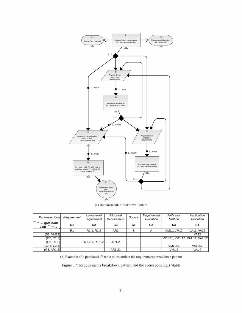
(a) Requirements Breakdown Pattern
Parameter Type Requirement Lower-level requirement
Allocated Requirement Source Requirement
AllocationVerification
MethodVerification Allocation
Data nodeJoin Point G1 G2 G3 C1 C2 S3 E1
R1 R1.1, R1.2 AR1 S A VM11, VM12 VA11, VA12(S3, VM12) VA22(G2, R1.1) VM1.11, VM1.12 VA1.11, VA1.12(G2, R1.2) R1.2.1, R1.2.2 AR1.2
(G2, R1.2.1) VM1.2.1 VA1.2.1(G3, AR1.2) AR1.21 VM1.2 VA1.2
(b) Example of a populated P -table to instantiate the requirements breakdown pattern
Figure 17: Requirements breakdown pattern and the corresponding P -table
31
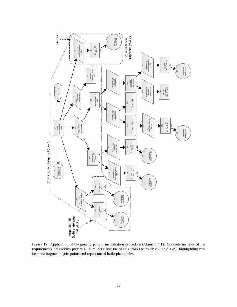
Row
inst
ance
frag
men
t (ro
w 1
)
Row
inst
ance
fra
gmen
t (ro
w 2
)
Join
poi
nt
Rep
etiti
on o
f B
oile
rpla
te a
fter
mul
tiplic
ity
Figure 18: Application of the generic pattern instantiation procedure (Algorithm 1): Concrete instance of the
requirements breakdown pattern (Figure 22) using the values from the P -table (Table 17b), highlighting row
instance fragments, join points and repetition of boilerplate nodes
32
6.2 Future WorkSeveral extensions could be made to the work presented in this report:
• The algorithm should be extended to multi-parameter nodes, as well for parameters that appear in multiple
nodes. The latter, however, can be addressed by our current instantiation algorithm by replicating the
parameter and the associated data in the pattern dataset.
• Algorithms to create data tables (in particular, join points) from source data should be developed.
• One design choice in the algorithm was to instantiate only those nodes for which parameters have values in
the data table. An alternative choice could be to use the whole pattern so that those data nodes that do not
take values in the table are also reproduced in the instance, but left as Uninstantiated (UI) or Uninstantiated
and Undeveloped (UU), as appropriate.
• Although we have given several semantic constraints on pattern well-formedness, we have yet to define the
corresponding algorithmic checks, i.e., for the multiplicity condition, well-foundedness (loop detection),
and for an argument being an instance of pattern.
• Much remains to be done on the basic theory. We have defined two forms of semantic judgement:
data ⊧ pattern data table complies with pattern (Def. 4.4)
pattern ⊑1 pattern pattern unfolds to pattern (Def. 3.7)
Though we defined the semantics of patterns, [[P ]], as the set of instance arguments (via ⊑1), we did not
give a direct denotational definition of [[P ]](τ), i.e., the specific instance induced by a set of data, nor a
judgement pattern ⇒data argument , which was instead defined algorithmically.
• We also need to define the notion of an argument satisfying a constraint, and give both semantic judgement,
syntactic proof rule, and algorithm.
We could also investigate constraints on the data invoked by the pattern variables, and extending the pat-
terns, themselves, with constraints.
• The relationship between modular abstractions, hierarchies [7], and patterns is, as yet, unclear although
there are a few examples of applying patterns within a modular organization [17].
• Patterns could be augmented with confidence aspects to indicate the level of support provided to the root
node of the pattern by applying the inference that the pattern specifies. Possibly, this could be represented
in the metadata, but is likely to require a more fundamental approach.
• There are similarities between pattern instantiation and refinement and concepts from the theory of graph
rewriting, and we plan to investigate the relationship.
• We implicitly use a notion of sequential composition of patterns. In fact, other ways of combining patterns
can be defined, and we have also developed a notion of parallel composition (not given in this report) to
create complex patterns (such as for requirements breakdown shown in Fig. 17a) from simpler patterns.
This leads to a notion of argument architecture, based on pattern composition.
• Pattern metadata could be drawn from an ontology. This would offer several advantages. Use of an
ontology tool and an automated import mechanism would save some effort, while enforcing constraints
from the ontology in the argument would provide a way of specializing a generic pattern for use in a
particular domain, and validating that its application does not violate domain-specific constraints.
33
References[1] E. Denney and G. Pai, “A lightweight methodology for safety case assembly,” in Proceedings of the 31st
International Conference on Computer Safety, Reliability and Security (SAFECOMP 2012), ser. LNCS,
F. Ortmeier and P. Daniel, Eds., vol. 7612. Springer-Verlag, Sep. 2012, pp. 1–12.
[2] T. Kelly and J. McDermid, “Safety case patterns – reusing successful arguments,” in IEE Colloquium onUnderstanding Patterns and Their Application to System Engineering (Digest No. 1998/308), Apr. 1998,
pp. 3/1–3/9.
[3] T. Kelly, “Arguing safety: A systematic approach to managing safety cases,” Ph.D. dissertation, University
of York, 1998.
[4] D. L. Parnas and J. Madey, “Functional documentation for computer systems engineering, vol. 2,” McMas-
ter University, Hamilton, Ontario, Tech. Rep. Technical Report CRL 237, Sept 1991.
[5] Goal Structuring Notation Working Group, “GSN Community Standard Version 1,” Nov. 2011. [Online].
Available: http://www.goalstructuringnotation.info/
[6] C. Menon, R. Hawkins, and J. McDermid, “Interim standard of best practice on software in the context of
DS 00-56 Issue 4,” Software Systems Engineering Initiative, University of York, Standard of Best Practice
Issue 1, 2009.
[7] E. Denney, G. Pai, and I. Whiteside, “Hierarchical safety cases,” in Proceedings of the 5th NASA FormalMethods Symposium, ser. LNCS, G. Brat, N. Rungta, and A. Venet, Eds., vol. 7871. Springer-Verlag, May
2013, pp. 478–483.
[8] E. Denney and G. Pai, “A Formal Basis for Safety Case Patterns,” in Computer Safety, Reliability andSecurity (SAFECOMP 2013), ser. LNCS, F. Bitsch, J. Guiochet, and M. Kaaniche, Eds., vol. 8153, 2013,
pp. 21–32.
[9] E. Denney, D. Naylor, and G. Pai, “Querying Safety Cases,” in 33rd International Conference on ComputerSafety, Reliability and Security (SAFECOMP 2014), A. Bondavalli and F. D. Giandomenico, Eds. Springer,
Sep. 2014, pp. 294–309.
[10] E. Denney, G. Pai, and I. Whiteside, “Formal foundations for hierarchical safety cases,” in Proceedings ofthe 16th IEEE International Symposium on High Assurance Systems Engineering (HASE 2015), Jan. 2015.
[11] L. Sun and T. Kelly, “Elaborating the concept of evidence in Safety Cases,” in Proceedings of the 21stSafety Critical Systems Symposium. Springer, Feb. 2013.
[12] E. Denney, I. Habli, and G. Pai, “Perspectives on Software Safety Case Development for Unmanned Air-
craft,” in Proceedings of the 42nd Annual IEEE/IFIP International Conference on Dependable Systems andNetworks (DSN 2012), Boston, MA, June 2012, pp. 1–8.
[13] E. Denney, G. Pai, and J. Pohl, “Automating the generation of heterogeneous aviation safety cases,” NASA
Ames Research Center, Technical Report NASA/CR-2011-215983, Aug. 2011.
[14] ——, “Heterogeneous aviation safety cases: Integrating the formal and the non-formal,” in 17th IEEEInternational Conference on Engineering of Complex Computer Systems (ICECCS), Paris, France, Jul.
2012, pp. 199–208.
[15] ——, “AdvoCATE: An Assurance Case Automation Toolset,” in SAFECOMP 2012 Workshops, ser. LNCS,
F. Ortmeier and P. Daniel, Eds., vol. 7613. Springer-Verlag, Sep. 2012.
[16] Object Management Group, “Structured Assurance Case Metamodel (SACM) version 1.0,” Formal/2013-
02-01, Feb. 2013.
34
[17] Industrial Avionics Working Group, “Modular Software Safety Case Process, Parts A and B: Process and
Guidance,” Tech. Rep. IAWG-AJT-301, Issue 2, Oct. 2007.
[18] R. Weaver, “The safety of software – constructing and assuring arguments,” Ph.D. dissertation, Dept. of
Computer Science, University of York, 2003.
[19] R. Alexander, T. Kelly, Z. Kurd, and J. McDermid, “Safety Cases for Advanced Control Software: Safety
Case Patterns,” University of York, Final Report for NASA Contract FA8655-07-1-3025, Oct. 2007.
[20] A. Ayoub, B. Kim, I. Lee, and O. Sokolsky, “A safety case pattern for model-based development approach,”
in Proceedings of the NASA Formal Methods Symposium (NFM), Apr. 2012.
[21] C. M. Holloway, “Making the Implicit Explicit: Towards an Assurance Case for DO-178C,” in Proceedingsof the 31st International System Safety Conference, Aug. 2013.
[22] RTCA SC-205 and EUROCAE WG-71, “Software Considerations in Airborne Systems and Equipment
Certification,” DO-178C / ED-12C, Dec. 2011.
35
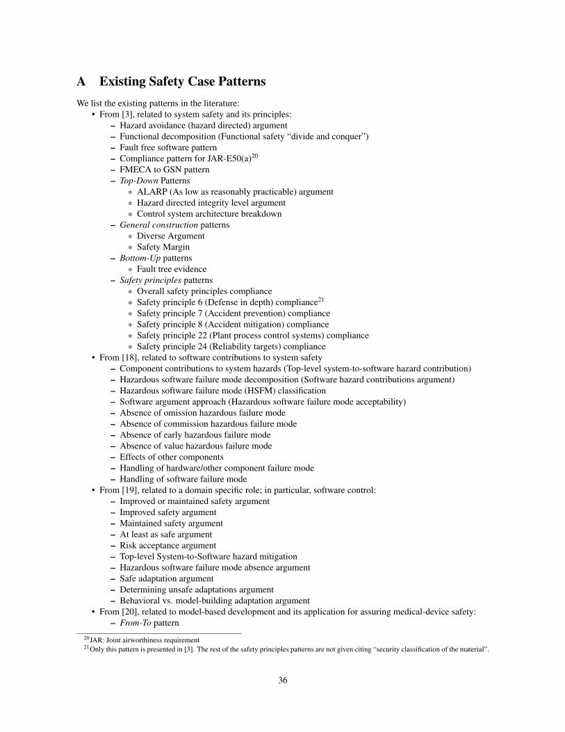
A Existing Safety Case PatternsWe list the existing patterns in the literature:
• From [3], related to system safety and its principles:
– Hazard avoidance (hazard directed) argument
– Functional decomposition (Functional safety “divide and conquer”)
– Fault free software pattern
– Compliance pattern for JAR-E50(a)20
– FMECA to GSN pattern
– Top-Down Patterns
* ALARP (As low as reasonably practicable) argument
* Hazard directed integrity level argument
* Control system architecture breakdown
– General construction patterns
* Diverse Argument
* Safety Margin
– Bottom-Up patterns
* Fault tree evidence
– Safety principles patterns
* Overall safety principles compliance
* Safety principle 6 (Defense in depth) compliance21
* Safety principle 7 (Accident prevention) compliance
* Safety principle 8 (Accident mitigation) compliance
* Safety principle 22 (Plant process control systems) compliance
* Safety principle 24 (Reliability targets) compliance
• From [18], related to software contributions to system safety
– Component contributions to system hazards (Top-level system-to-software hazard contribution)
– Hazardous software failure mode decomposition (Software hazard contributions argument)
– Hazardous software failure mode (HSFM) classification
– Software argument approach (Hazardous software failure mode acceptability)
– Absence of omission hazardous failure mode
– Absence of commission hazardous failure mode
– Absence of early hazardous failure mode
– Absence of value hazardous failure mode
– Effects of other components
– Handling of hardware/other component failure mode
– Handling of software failure mode
• From [19], related to a domain specific role; in particular, software control:
– Improved or maintained safety argument
– Improved safety argument
– Maintained safety argument
– At least as safe argument
– Risk acceptance argument
– Top-level System-to-Software hazard mitigation
– Hazardous software failure mode absence argument
– Safe adaptation argument
– Determining unsafe adaptations argument
– Behavioral vs. model-building adaptation argument
• From [20], related to model-based development and its application for assuring medical-device safety:
– From-To pattern
20JAR: Joint airworthiness requirement21Only this pattern is presented in [3]. The rest of the safety principles patterns are not given citing “security classification of the material”.
36
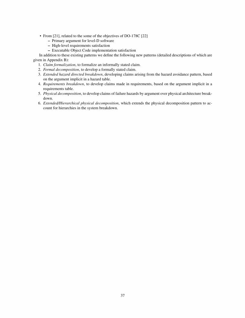
• From [21], related to the some of the objectives of DO-178C [22]
– Primary argument for level-D software
– High-level requirements satisfaction
– Executable Object Code implementation satisfaction
In addition to these existing patterns we define the following new patterns (detailed descriptions of which are
given in Appendix B):
1. Claim formalization, to formalize an informally stated claim.
2. Formal decomposition, to develop a formally stated claim.
3. Extended hazard directed breakdown, developing claims arising from the hazard avoidance pattern, based
on the argument implicit in a hazard table.
4. Requirements breakdown, to develop claims made in requirements, based on the argument implicit in a
requirements table.
5. Physical decomposition, to develop claims of failure hazards by argument over physical architecture break-
down.
6. Extended/Hierarchical physical decomposition, which extends the physical decomposition pattern to ac-
count for hierarchies in the system breakdown.
37
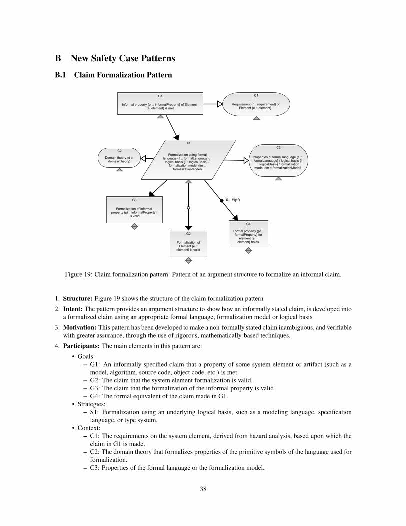
B New Safety Case Patterns
B.1 Claim Formalization Pattern
Figure 19: Claim formalization pattern: Pattern of an argument structure to formalize an informal claim.
1. Structure: Figure 19 shows the structure of the claim formalization pattern
2. Intent: The pattern provides an argument structure to show how an informally stated claim, is developed into
a formalized claim using an appropriate formal language, formalization model or logical basis
3. Motivation: This pattern has been developed to make a non-formally stated claim inambiguous, and verifiable
with greater assurance, through the use of rigorous, mathematically-based techniques.
4. Participants: The main elements in this pattern are:
• Goals:
– G1: An informally specified claim that a property of some system element or artifact (such as a
model, algorithm, source code, object code, etc.) is met.
– G2: The claim that the system element formalization is valid.
– G3: The claim that the formalization of the informal property is valid
– G4: The formal equivalent of the claim made in G1.
• Strategies:
– S1: Formalization using an underlying logical basis, such as a modeling language, specification
language, or type system.
• Context:
– C1: The requirements on the system element, derived from hazard analysis, based upon which the
claim in G1 is made.
– C2: The domain theory that formalizes properties of the primitive symbols of the language used for
formalization.
– C3: Properties of the formal language or the formalization model.
38
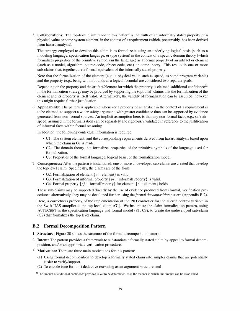
5. Collaborations: The top-level claim made in this pattern is the truth of an informally stated property of a
physical value or some system element, in the context of a requirement (which, presumably, has been derived
from hazard analysis).
The strategy employed to develop this claim is to formalize it using an underlying logical basis (such as a
modeling language, specification language, or type system) in the context of a specific domain theory (which
formalizes properties of the primitive symbols in the language) as a formal property of an artifact or element
(such as a model, algorithm, source code, object code, etc.) in some theory. This results in one or more
sub-claims that, together, are a formal equivalent of the informally stated property.
Note that the formalization of the element (e.g., a physical value such as speed, as some program variable)
and the property (e.g., being within bounds as a logical formula) are considered two separate goals.
Depending on the property and the artifact/element for which the property is claimed, additional confidence22
in the formalization strategy may be provided by supporting the (optional) claims that the formalization of the
element and its property is itself valid. Alternatively, the validity of formalization can be assumed; however
this might require further justification.
6. Applicability: The pattern is applicable whenever a property of an artifact in the context of a requirement is
to be claimed, to support a wider safety argument, with greater confidence than can be supported by evidence
generated from non-formal sources. An implicit assumption here, is that any non-formal facts, e.g., safe air-
speed, assumed in the formalization can be separately and rigorously validated in reference to the justification
of informal facts within formal reasoning.
In addition, the following contextual information is required:
• C1: The system element, and the corresponding requirements derived from hazard analysis based upon
which the claim in G1 is made.
• C2: The domain theory that formalizes properties of the primitive symbols of the language used for
formalization.
• C3: Properties of the formal language, logical basis, or the formalization model.
7. Consequences: After the pattern is instantiated, one or more undeveloped sub-claims are created that develop
the top-level claim. Specifically, the claims are of the form:
• G2. Formalization of element {e :: element} is valid.
• G3. Formalization of informal property {pi :: informalProperty} is valid.
• G4. Formal property {pf :: formalProperty} for element {e :: element} holds
These sub-claims may be supported directly by the use of evidence produced from (formal) verification pro-
cedures; alternatively, they may be developed further using the formal decomposition pattern (Appendix B.2).
Here, a correctness property of the implementation of the PID controller for the aileron control variable in
the Swift UAS autopilot is the top level claim (G1). We instantiate the claim formalization pattern, using
AUTOCERT as the specification language and formal model (S1, C3), to create the undeveloped sub-claim
(G2) that formalizes the top level claim.
B.2 Formal Decomposition Pattern1. Structure: Figure 20 shows the structure of the formal decomposition pattern.
2. Intent: The pattern provides a framework to substantiate a formally stated claim by appeal to formal decom-
position, and/or an appropriate verification procedure.
3. Motivation: There are three main motivations for this pattern:
(1) Using formal decomposition to develop a formally stated claim into simpler claims that are potentially
easier to verify/support.
(2) To encode (one form of) deductive reasoning as an argument structure, and
22The amount of additional confidence provided is yet to be determined, as is the manner in which this amount can be established.
39
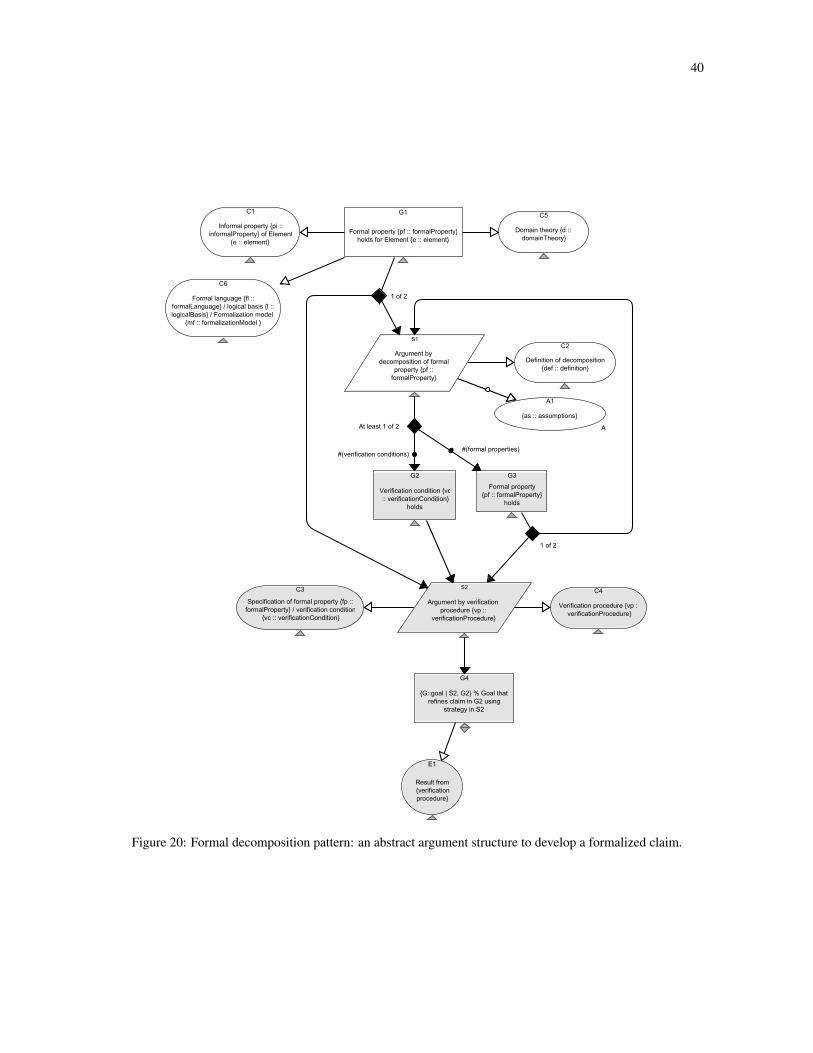
40
Figure 20: Formal decomposition pattern: an abstract argument structure to develop a formalized claim.
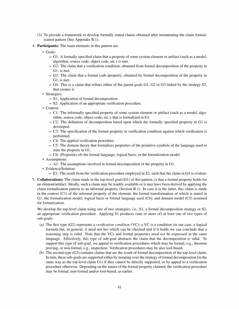
(3) To provide a framework to develop formally stated claims obtained after instantiating the claim formal-
ization pattern (See Appendix B.1).
4. Participants: The main elements in this pattern are:
• Goals:
– G1: A formally specified claim that a property of some system element or artifact (such as a model,
algorithm, source code, object code, etc.) is met.
– G2: The claim that a verification condition, obtained from formal decomposition of the property in
G1, is met.
– G3: The claim that a formal (sub-)property, obtained by formal decomposition of the property in
G1, is met.
– G4: This is a claim that refines either of the parent goals G1, G2 or G3 linked by the strategy S2,
that creates it.
• Strategies:
– S1: Application of formal decomposition.
– S2: Application of an appropriate verification procedure.
• Context:
– C1: The informally specified property of some system element or artifact (such as a model, algo-
rithm, source code, object code, etc.), that is formalized in G1.
– C2: The definition of decomposition based upon which the formally specified property in G1 is
developed.
– C3: The specification of the formal property or verification condition against which verification is
performed.
– C4: The applied verification procedure.
– C5: The domain theory that formalizes properties of the primitive symbols of the language used to
state the property in G1.
– C6: (Properties of) the formal language, logical basis, or the formalization model.
• Assumptions:
– A1: The assumptions involved in formal decomposition of the property in G1.
• Evidence/Solution:
– E1: The result from the verification procedure employed in S2, such that the claim in G4 is evident.
5. Collaborations: The claim made in the top-level goal (G1) of this pattern, is that a formal property holds for
an element/artifact. Ideally, such a claim may be readily available or it may have been derived by applying the
claim formalization pattern to an informal property (Section B.1). In case it is the latter, this claim is made
in the context (C1) of the informal property of the element, the formal transformation of which is stated in
G1, the formalization model, logical basis or formal language used (C6), and domain model (C5) assumed
for formalization.
We develop the top-level claim using one of two strategies, i.e., S1, a formal decomposition strategy or S2,
an appropriate verification procedure. Applying S1 produces (one or more of) at least one of two types of
sub-goals:
(a) The first type (G2) represents a verification condition (VC); a VC is a condition (in our case, a logical
formula but, in general, it need not be) which can be checked and if it holds we can conclude that a
reasoning step is valid. Note that the VCs and formal properties need not be expressed in the same
language. Effectively, this type of sub-goal abstracts the claim that the decomposition is valid. To
support this type of sub-goal, we appeal to verification procedures which may be formal, e.g., theorem
proving, or non-formal, e.g., inspection. Verification procedures may be also tool-based.
(b) The second type (G3) contains claims that are the result of formal decomposition of the top-level claim.
In turn, these sub-goals are supported either by iterating over the strategy of formal decomposition (in the
same way as the top-level claim G1) if they cannot be directly supported, or by appeal to a verification
procedure otherwise. Depending on the nature of the formal property claimed, the verification procedure
may be formal, non-formal and/or tool-based, as earlier.
41
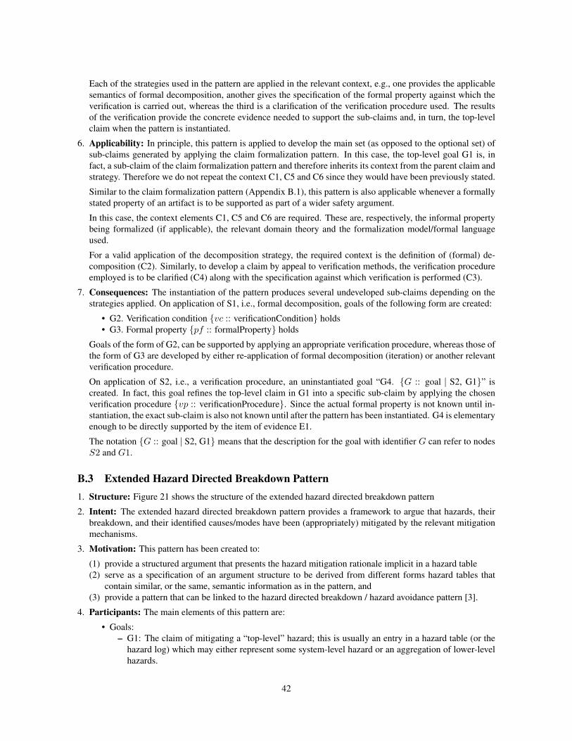
Each of the strategies used in the pattern are applied in the relevant context, e.g., one provides the applicable
semantics of formal decomposition, another gives the specification of the formal property against which the
verification is carried out, whereas the third is a clarification of the verification procedure used. The results
of the verification provide the concrete evidence needed to support the sub-claims and, in turn, the top-level
claim when the pattern is instantiated.
6. Applicability: In principle, this pattern is applied to develop the main set (as opposed to the optional set) of
sub-claims generated by applying the claim formalization pattern. In this case, the top-level goal G1 is, in
fact, a sub-claim of the claim formalization pattern and therefore inherits its context from the parent claim and
strategy. Therefore we do not repeat the context C1, C5 and C6 since they would have been previously stated.
Similar to the claim formalization pattern (Appendix B.1), this pattern is also applicable whenever a formally
stated property of an artifact is to be supported as part of a wider safety argument.
In this case, the context elements C1, C5 and C6 are required. These are, respectively, the informal property
being formalized (if applicable), the relevant domain theory and the formalization model/formal language
used.
For a valid application of the decomposition strategy, the required context is the definition of (formal) de-
composition (C2). Similarly, to develop a claim by appeal to verification methods, the verification procedure
employed is to be clarified (C4) along with the specification against which verification is performed (C3).
7. Consequences: The instantiation of the pattern produces several undeveloped sub-claims depending on the
strategies applied. On application of S1, i.e., formal decomposition, goals of the following form are created:
• G2. Verification condition {vc :: verificationCondition} holds
• G3. Formal property {pf :: formalProperty} holds
Goals of the form of G2, can be supported by applying an appropriate verification procedure, whereas those of
the form of G3 are developed by either re-application of formal decomposition (iteration) or another relevant
verification procedure.
On application of S2, i.e., a verification procedure, an uninstantiated goal “G4. {G :: goal ∣ S2, G1}” is
created. In fact, this goal refines the top-level claim in G1 into a specific sub-claim by applying the chosen
verification procedure {vp :: verificationProcedure}. Since the actual formal property is not known until in-
stantiation, the exact sub-claim is also not known until after the pattern has been instantiated. G4 is elementary
enough to be directly supported by the item of evidence E1.
The notation {G :: goal ∣ S2, G1} means that the description for the goal with identifier G can refer to nodes
S2 and G1.
B.3 Extended Hazard Directed Breakdown Pattern1. Structure: Figure 21 shows the structure of the extended hazard directed breakdown pattern
2. Intent: The extended hazard directed breakdown pattern provides a framework to argue that hazards, their
breakdown, and their identified causes/modes have been (appropriately) mitigated by the relevant mitigation
mechanisms.
3. Motivation: This pattern has been created to:
(1) provide a structured argument that presents the hazard mitigation rationale implicit in a hazard table
(2) serve as a specification of an argument structure to be derived from different forms hazard tables that
contain similar, or the same, semantic information as in the pattern, and
(3) provide a pattern that can be linked to the hazard directed breakdown / hazard avoidance pattern [3].
4. Participants: The main elements of this pattern are:
• Goals:
– G1: The claim of mitigating a “top-level” hazard; this is usually an entry in a hazard table (or the
hazard log) which may either represent some system-level hazard or an aggregation of lower-level
hazards.
42
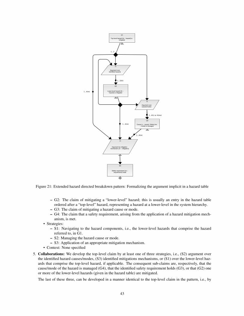
Figure 21: Extended hazard directed breakdown pattern: Formalizing the argument implicit in a hazard table
– G2: The claim of mitigating a “lower-level” hazard; this is usually an entry in the hazard table
ordered after a “top-level” hazard, representing a hazard at a lower-level in the system hierarchy.
– G3: The claim of mitigating a hazard cause or mode.
– G4: The claim that a safety requirement, arising from the application of a hazard mitigation mech-
anism, is met.
• Strategies:
– S1: Navigating to the hazard components, i.e., the lower-level hazards that comprise the hazard
referred to, in G1.
– S2: Managing the hazard cause or mode.
– S3: Application of an appropriate mitigation mechanism.
• Context: None specified
5. Collaborations: We develop the top-level claim by at least one of three strategies, i.e., (S2) argument over
the identified hazard causes/modes, (S3) identified mitigations mechanisms, or (S1) over the lower-level haz-
ards that comprise the top-level hazard, if applicable. The consequent sub-claims are, respectively, that the
cause/mode of the hazard is managed (G4), that the identified safety requirement holds (G3), or that (G2) one
or more of the lower-level hazards (given in the hazard table) are mitigated.
The last of these three, can be developed in a manner identical to the top-level claim in the pattern, i.e., by
43
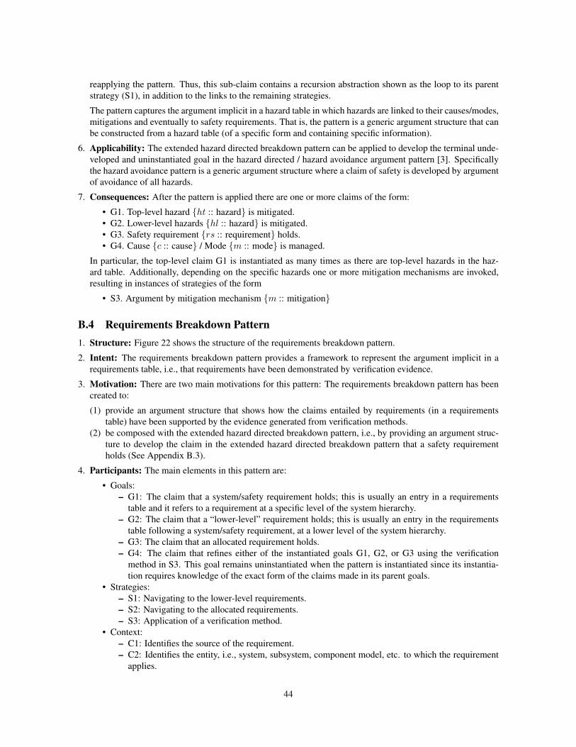
reapplying the pattern. Thus, this sub-claim contains a recursion abstraction shown as the loop to its parent
strategy (S1), in addition to the links to the remaining strategies.
The pattern captures the argument implicit in a hazard table in which hazards are linked to their causes/modes,
mitigations and eventually to safety requirements. That is, the pattern is a generic argument structure that can
be constructed from a hazard table (of a specific form and containing specific information).
6. Applicability: The extended hazard directed breakdown pattern can be applied to develop the terminal unde-
veloped and uninstantiated goal in the hazard directed / hazard avoidance argument pattern [3]. Specifically
the hazard avoidance pattern is a generic argument structure where a claim of safety is developed by argument
of avoidance of all hazards.
7. Consequences: After the pattern is applied there are one or more claims of the form:
• G1. Top-level hazard {ht :: hazard} is mitigated.
• G2. Lower-level hazards {hl :: hazard} is mitigated.
• G3. Safety requirement {rs :: requirement} holds.
• G4. Cause {c :: cause} / Mode {m :: mode} is managed.
In particular, the top-level claim G1 is instantiated as many times as there are top-level hazards in the haz-
ard table. Additionally, depending on the specific hazards one or more mitigation mechanisms are invoked,
resulting in instances of strategies of the form
• S3. Argument by mitigation mechanism {m :: mitigation}
B.4 Requirements Breakdown Pattern1. Structure: Figure 22 shows the structure of the requirements breakdown pattern.
2. Intent: The requirements breakdown pattern provides a framework to represent the argument implicit in a
requirements table, i.e., that requirements have been demonstrated by verification evidence.
3. Motivation: There are two main motivations for this pattern: The requirements breakdown pattern has been
created to:
(1) provide an argument structure that shows how the claims entailed by requirements (in a requirements
table) have been supported by the evidence generated from verification methods.
(2) be composed with the extended hazard directed breakdown pattern, i.e., by providing an argument struc-
ture to develop the claim in the extended hazard directed breakdown pattern that a safety requirement
holds (See Appendix B.3).
4. Participants: The main elements in this pattern are:
• Goals:
– G1: The claim that a system/safety requirement holds; this is usually an entry in a requirements
table and it refers to a requirement at a specific level of the system hierarchy.
– G2: The claim that a “lower-level” requirement holds; this is usually an entry in the requirements
table following a system/safety requirement, at a lower level of the system hierarchy.
– G3: The claim that an allocated requirement holds.
– G4: The claim that refines either of the instantiated goals G1, G2, or G3 using the verification
method in S3. This goal remains uninstantiated when the pattern is instantiated since its instantia-
tion requires knowledge of the exact form of the claims made in its parent goals.
• Strategies:
– S1: Navigating to the lower-level requirements.
– S2: Navigating to the allocated requirements.
– S3: Application of a verification method.
• Context:
– C1: Identifies the source of the requirement.
– C2: Identifies the entity, i.e., system, subsystem, component model, etc. to which the requirement
applies.
44
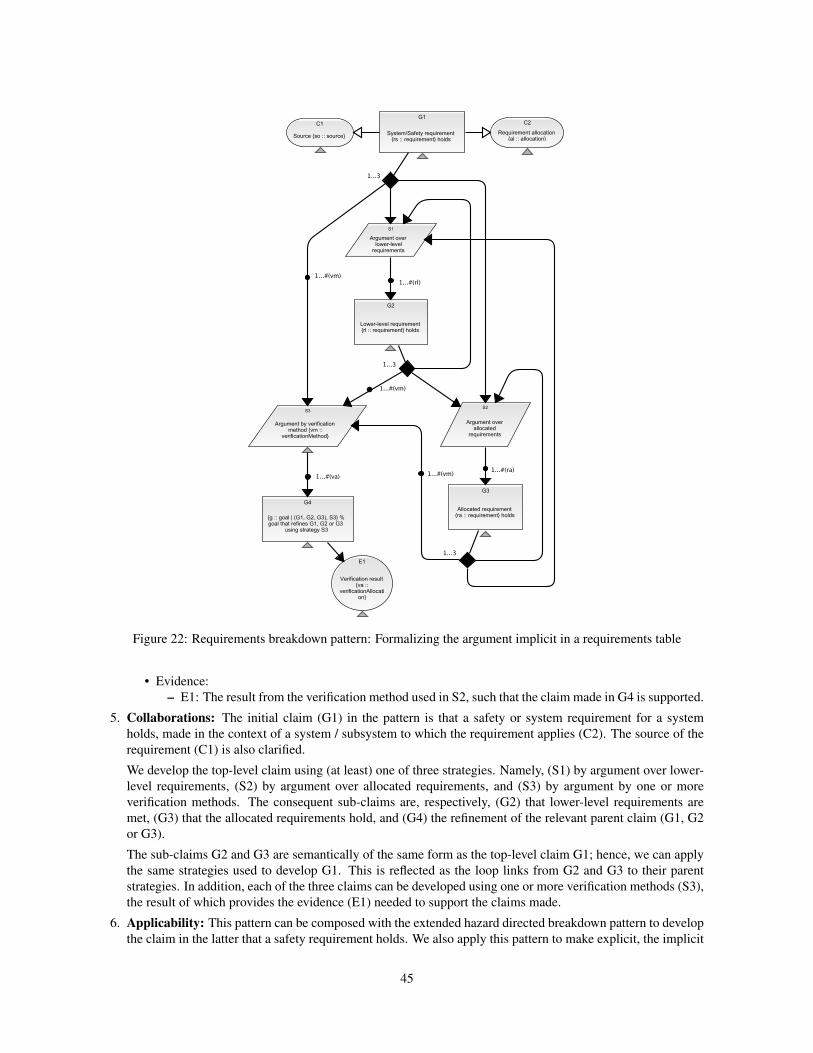
Figure 22: Requirements breakdown pattern: Formalizing the argument implicit in a requirements table
• Evidence:
– E1: The result from the verification method used in S2, such that the claim made in G4 is supported.
5. Collaborations: The initial claim (G1) in the pattern is that a safety or system requirement for a system
holds, made in the context of a system / subsystem to which the requirement applies (C2). The source of the
requirement (C1) is also clarified.
We develop the top-level claim using (at least) one of three strategies. Namely, (S1) by argument over lower-
level requirements, (S2) by argument over allocated requirements, and (S3) by argument by one or more
verification methods. The consequent sub-claims are, respectively, (G2) that lower-level requirements are
met, (G3) that the allocated requirements hold, and (G4) the refinement of the relevant parent claim (G1, G2
or G3).
The sub-claims G2 and G3 are semantically of the same form as the top-level claim G1; hence, we can apply
the same strategies used to develop G1. This is reflected as the loop links from G2 and G3 to their parent
strategies. In addition, each of the three claims can be developed using one or more verification methods (S3),
the result of which provides the evidence (E1) needed to support the claims made.
6. Applicability: This pattern can be composed with the extended hazard directed breakdown pattern to develop
the claim in the latter that a safety requirement holds. We also apply this pattern to make explicit, the implicit
45
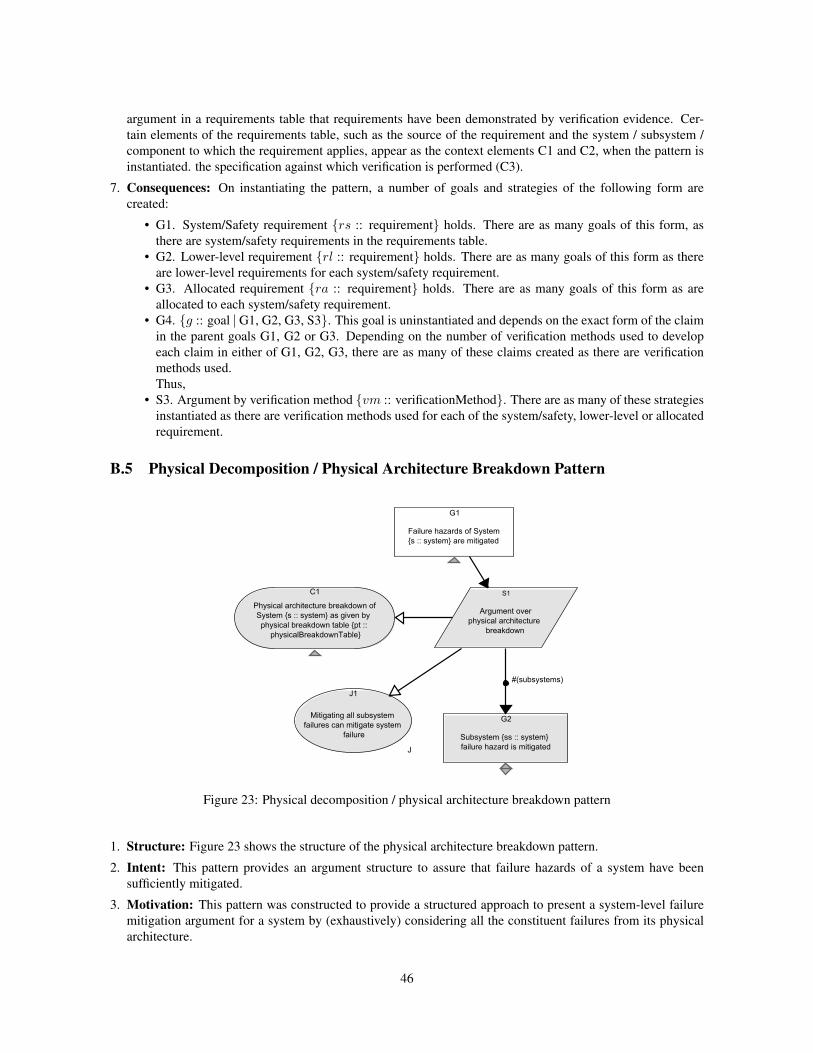
argument in a requirements table that requirements have been demonstrated by verification evidence. Cer-
tain elements of the requirements table, such as the source of the requirement and the system / subsystem /
component to which the requirement applies, appear as the context elements C1 and C2, when the pattern is
instantiated. the specification against which verification is performed (C3).
7. Consequences: On instantiating the pattern, a number of goals and strategies of the following form are
created:
• G1. System/Safety requirement {rs :: requirement} holds. There are as many goals of this form, as
there are system/safety requirements in the requirements table.
• G2. Lower-level requirement {rl :: requirement} holds. There are as many goals of this form as there
are lower-level requirements for each system/safety requirement.
• G3. Allocated requirement {ra :: requirement} holds. There are as many goals of this form as are
allocated to each system/safety requirement.
• G4. {g :: goal ∣ G1, G2, G3, S3}. This goal is uninstantiated and depends on the exact form of the claim
in the parent goals G1, G2 or G3. Depending on the number of verification methods used to develop
each claim in either of G1, G2, G3, there are as many of these claims created as there are verification
methods used.
Thus,
• S3. Argument by verification method {vm :: verificationMethod}. There are as many of these strategies
instantiated as there are verification methods used for each of the system/safety, lower-level or allocated
requirement.
B.5 Physical Decomposition / Physical Architecture Breakdown Pattern
Figure 23: Physical decomposition / physical architecture breakdown pattern
1. Structure: Figure 23 shows the structure of the physical architecture breakdown pattern.
2. Intent: This pattern provides an argument structure to assure that failure hazards of a system have been
sufficiently mitigated.
3. Motivation: This pattern was constructed to provide a structured approach to present a system-level failure
mitigation argument for a system by (exhaustively) considering all the constituent failures from its physical
architecture.
46
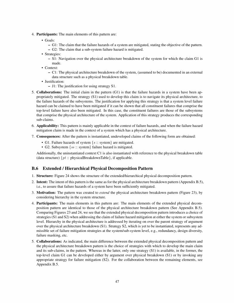
4. Participants: The main elements of this pattern are:
• Goals:
– G1: The claim that the failure hazards of a system are mitigated, stating the objective of the pattern.
– G2: The claim that a sub-system failure hazard is mitigated.
• Strategies:
– S1: Navigation over the physical architecture breakdown of the system for which the claim G1 is
made.
• Context:
– C1: The physical architecture breakdown of the system, (assumed to be) documented in an external
data structure such as a physical breakdown table.
• Justification:
– J1: The justification for using strategy S1.
5. Collaborations: The initial claim in the pattern (G1) is that the failure hazards in a system have been ap-
propriately mitigated. The strategy (S1) used to develop this claim is to navigate its physical architecture, to
the failure hazards of the subsystems. The justification for applying this strategy is that a system level failure
hazard can be claimed to have been mitigated if it can be shown that all constituent failures that comprise the
top-level failure have also been mitigated. In this case, the constituent failures are those of the subsystems
that comprise the physical architecture of the system. Application of this strategy produces the corresponding
sub-claims.
6. Applicability: This pattern is mainly applicable in the context of failure hazards, and when the failure hazard
mitigation claim is made in the context of a system which has a physical architecture.
7. Consequences: After the pattern is instantiated, undeveloped claims of the following form are obtained:
• G1. Failure hazards of system {s :: system} are mitigated.
• G2. Subsystem {ss :: system} failure hazard is mitigated.
Additionally, the uninstantiated context C1 is also instantiated with reference to the physical breakdown table
(data structure) {pt :: physicalBreakdownTable}, if applicable.
B.6 Extended / Hierarchical Physical Decomposition Pattern1. Structure: Figure 24 shows the structure of the extended/hierarchical physical decomposition pattern.
2. Intent: The intent of this pattern is the same as for the physical architecture breakdown pattern (Appendix B.5),
i.e., to assure that failure hazards of a system have been sufficiently mitigated.
3. Motivation: The pattern was created to extend the physical architecture breakdown pattern (Figure 23), by
considering hierarchy in the system structure.
4. Participants: The main elements in this pattern are: The main elements of the extended physical decom-
position pattern are identical to those of the physical architecture breakdown pattern (See Appendix B.5).
Comparing Figures 23 and 24, we see that the extended physical decomposition pattern introduces a choice of
strategies (S1 and S2) when addressing the claim of failure hazard mitigation at either the system or subsystem
level. Hierarchy in the physical architecture is addressed by iterating on over the parent strategy of argument
over the physical architecture breakdown (S1). Strategy S2, which is yet to be instantiated, represents any ad-
missible set of failure mitigation strategies at the system/sub-system level, e.g., redundancy, design diversity,
failure masking, etc.
5. Collaborations: As indicated, the main difference between the extended physical decomposition pattern and
the physical architecture breakdown pattern is the choice of strategies with which to develop the main claim
and its sub-claims, in the pattern. Whereas in the latter, only one strategy (S1) is available, in the former, the
top-level claim G1 can be developed either by argument over physical breakdown (S1) or by invoking any
appropriate strategy for failure mitigation (S2). For the collaboration between the remaining elements, see
Appendix B.5.
47
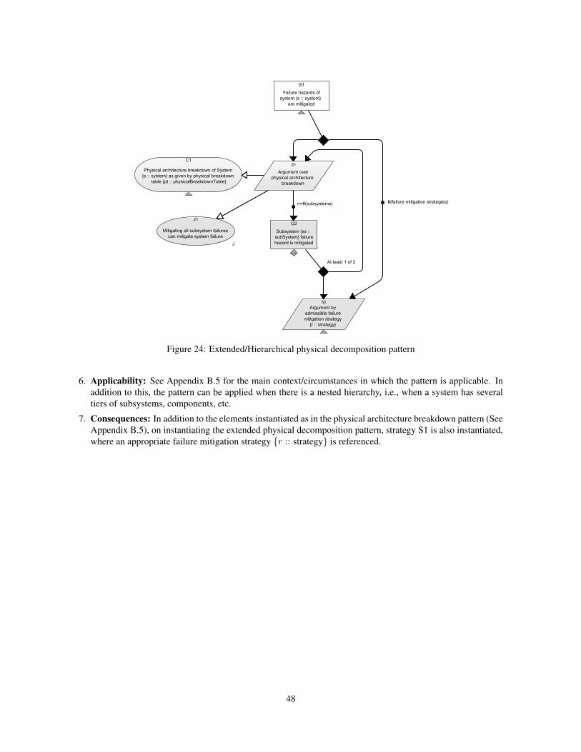
Figure 24: Extended/Hierarchical physical decomposition pattern
6. Applicability: See Appendix B.5 for the main context/circumstances in which the pattern is applicable. In
addition to this, the pattern can be applied when there is a nested hierarchy, i.e., when a system has several
tiers of subsystems, components, etc.
7. Consequences: In addition to the elements instantiated as in the physical architecture breakdown pattern (See
Appendix B.5), on instantiating the extended physical decomposition pattern, strategy S1 is also instantiated,
where an appropriate failure mitigation strategy {r :: strategy} is referenced.
48
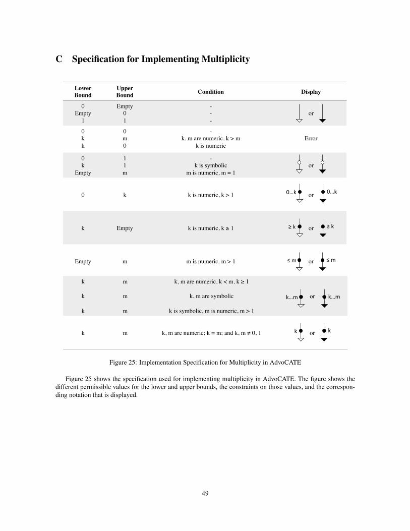
C Specification for Implementing Multiplicity
Lower Bound
Upper Bound Condition Display
0Empty
1
Empty01
---
or
0kk
0m0
-k, m are numeric, k > m
k is numericError
0k
Empty
11m
-k is symbolic
m is numeric, m = 1or
0 k k is numeric, k > 1 or
k Empty k is numeric, k ≥ 1 or
Empty m m is numeric, m > 1 or
k
k
k
m
m
m
k, m are numeric, k < m, k ≥ 1
k, m are symbolic
k is symbolic, m is numeric, m > 1
or
k m k, m are numeric; k = m; and k, m ≠ 0, 1 or
Figure 25: Implementation Specification for Multiplicity in AdvoCATE
Figure 25 shows the specification used for implementing multiplicity in AdvoCATE. The figure shows the
different permissible values for the lower and upper bounds, the constraints on those values, and the correspon-
ding notation that is displayed.
49