Embed Size (px)
Citation preview
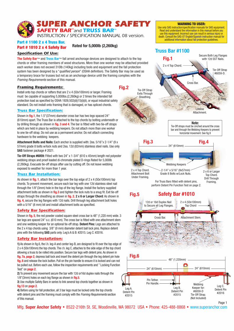
SAFETY BAR™and TRUSS BAR™
INSTRUCTION / SPECIFICATION MANUAL 08 version.
Page 1
WARNING TO USER:Use only SAS instruction/specification manuals for SAS equipment.
Read and understand the information in this manual before you use this equipment. Incorrect use can result in serious injury or
death. Consult the SAS-07 English/Spanish instruction manual for additional information about fall protection guidelines.
Part # 1100 2 x 4 Truss Bar.
Part # 1010 2 x 4 Safety Bar
Mfg. Super Anchor Safety w 8522-216th St. SE, Woodinville, WA 98072 USA w Phone: 425-488-8868 w www.superanchor.com
Rated for 5,000lb (2,260kg)
Fig.1
Truss Bar #1100
2 x 4 Top Chord.
Secure Both Leg Flanges with 12d SST Nails.
Tie-Off Strap#6059-D.
Cross Bar.
D-Ring.
LifelineAttachment.
Fig.3 Fig.424” (610mm)
Webbing Keepers
2 x 4 Top Chord.Attachment BoltUnder Framing.
2 x 6 or Larger Top Chord.
Drill Through Framing.
2-1/4” x 5/16” (9x57mm) Grade 8 Bolts w/Lock Nuts.
Fig.2Tie-Off StrapExits Through
Sheathing.
Note: Tie-Off straps must be cinched around the cross bar and through the Webbing Keepers to prevent
horizontal movement. See fig.9
Safety Bar #1010Fig.5
12d or 16d Duplex Nail to Secure all Leg Flanges.
Attachment Stem.Cross Bar.
2 x 4 (50x100mm) Top Chord
Pin Tether.Pin Handle.
48” (1,220mm)
24” (610mm) 24” (610mm)
Leg A.Detent Pin
#2015
Leg B.Detent Pin
#2015
Leg C.Detent Pin
#2016
Webbing Keeper for:#6059-D
Tie-Off Strap. (Not Included)
Fig.6
Specification Of Use:
The Safety Bar™ and Truss Bar™ fall arrest anchorage devices are designed to attach to the top
chords or other framing members of wood structures. More than one worker may be attached provided
each worker does not exceed 310lb (140kg) including tools and equipment and the fall protection
system has been designed by a “qualified person” (OSHA definition). The Safety Bar may be used as
a temporary brace for trusses but not as an anchorage device until the framing complies with the
Framing Requirements section of this manual.
Framing Requirements:
Install onto top chords or rafters that are 2 x 4 (50x100mm) or larger. Framing
must be capable of supporting 5,000lbs.(2,260kg) or 2 times the intended fall
protection load as specified by OSHA 1926;502(d)(15)(i)(ii), or equal industrial safety
standard. Do not install onto framing that is damaged, or has spliced chords.
Truss Bar Specification:
Shown in fig.1, the 1.5”(37mm) diameter cross bar has two legs spaced 24”
(610mm) apart. The Truss Bar is attached to the top chords by bolting underneath or
by drilling through as shown in fig. 3 and 4. The bar is fitted with two tie-off straps
which are held in place by webbing keepers. Do not attach more than one worker
to one tie-off strap. Do not use as a permanent anchor. Do not attach connecting
hardware to the webbing keepers.
Attachment Bolts and Nails: Each anchor is supplied with: 2ea. 5/16”x 2-1/4” (9 x
57mm) grade 8 bolts w/lock nuts and 2ea. 12d (82mm) stainless steel nails. Use only
SAS fastener package # 2021.
Tie-Off Straps #6059: Fitted with two 24” x 1-3/4” (610 x 45mm) length red polyester
webbing straps and proof loaded di-chromate plated D-rings Rated for 5,000lb
(2,260kg). Evacuate tie-off straps after use by cutting off. Do not leave webbing
exposed to weather for more than 1 year.
Truss Bar Installation:
As shown in fig. 1, attach the bar legs over the top edge of 2 x 4 (50x100mm) top
chords. To prevent movement, secure each bar leg with one 12d stainless steel nail
through the 1/8”(3mm) hole in the top of the leg flange. Install the factory supplied
attachment bolts as shown in fig.3 and tighten the lock nuts to a snug fit. Exit tie-off
straps through the sheathing as shown in fig. 2. 2 x 6 or Larger Chord: As shown in
fig. 4, secure the leg flanges with 12d nails. Drill through leg attachment bolt holes
with a 5/16” (8 mm) bit and install attachment bolts as specified.
Safety Bar Specification:
Shown in fig. 5, the red powder coated square steel cross bar is 48” (1,220 mm) wide. 3
bar legs are spaced 24” o.c. (610 mm). The cross bar is fitted with one attachment stem
and one webbing keeper for an optional tie-off strap. Detent Pins: Legs are attached to
the 2 x 4 top chords using 3/8” (9 mm) diameter detent ball lock pins. Replace detent
pins with the following SAS parts only: Leg’s A & B: #2015. Leg C: #2016.
Safety Bar Installation:
1) As shown in fig.6, the l.h. leg-A and center leg-B, are designed to fit over the top edge of
2 x 4 (50x100mm) the top chords. The r.h. leg C, attaches to the side edge of the top chord
allowing a truss to be rolled into position. Secure bar legs with detent pins. As shown in
fig. 7a, page 2, depress ball lock and insert the detent pin through the leg detent pin hole
fig. 8 and release the lock button. Pull on the pin handle to ensure it is locked and can not
be pulled out. Before each use, follow the inspection requirements and ” Locking Function
Test” on page 2.
2) To prevent any movement secure the bar with 12d or16d duplex nails through the
1/8”(3mm) holes on each leg flange as shown in fig.5.
3) Use multiple Safety Bars in series to link several top chords together as shown in
fig.13 on page 2.
4) Before using for fall protection, all 3 bar legs must be locked onto the top chords
with detent pins and the framing must comply with the Framing Requirements section
of this manual.
For Truss Bars fitted with detent pins,
perform Detent Pin Function Test on page 2.
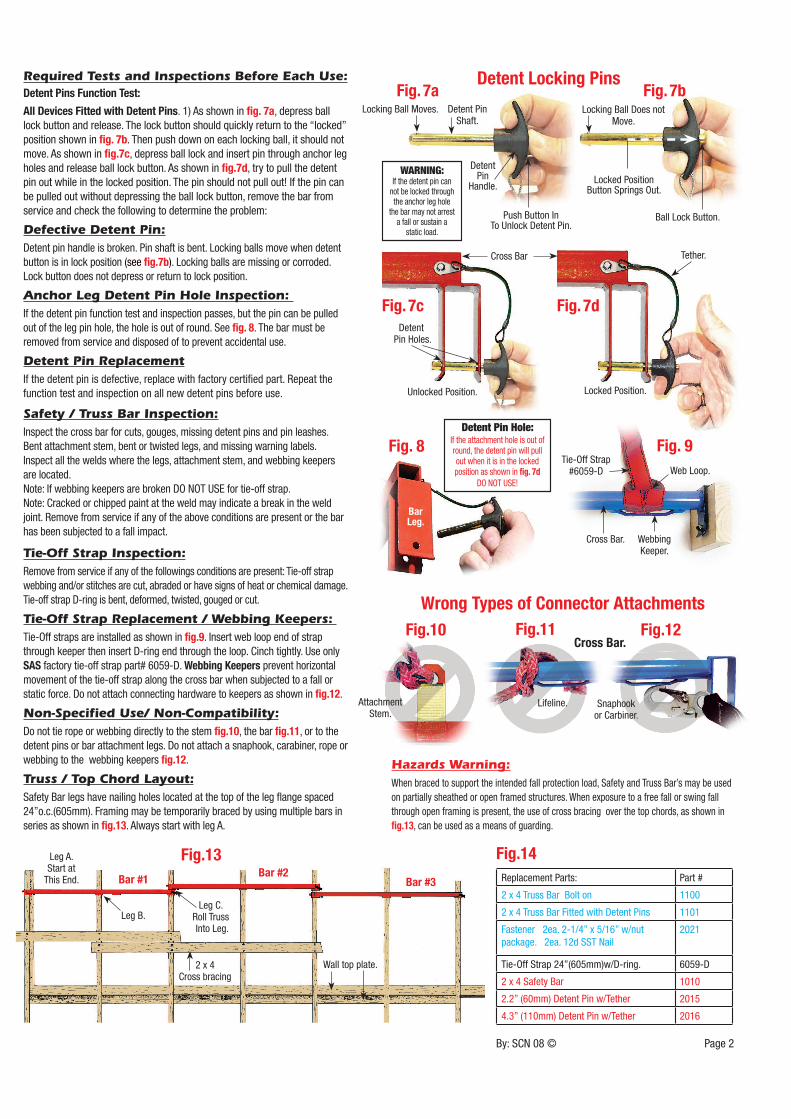
Fig.10 Fig.11 Fig.12
AttachmentStem.
Lifeline.
Cross Bar.
Snaphook or Carbiner.
By: SCN 08 © Page 2
Required Tests and Inspections Before Each Use:
Detent Pins Function Test:
All Devices Fitted with Detent Pins. 1) As shown in fig. 7a, depress ball
lock button and release. The lock button should quickly return to the “locked”
position shown in fig. 7b. Then push down on each locking ball, it should not
move. As shown in fig.7c, depress ball lock and insert pin through anchor leg
holes and release ball lock button. As shown in fig.7d, try to pull the detent
pin out while in the locked position. The pin should not pull out! If the pin can
be pulled out without depressing the ball lock button, remove the bar from
service and check the following to determine the problem:
Defective Detent Pin:
Detent pin handle is broken. Pin shaft is bent. Locking balls move when detent
button is in lock position (see fig.7b). Locking balls are missing or corroded.
Lock button does not depress or return to lock position.
Anchor Leg Detent Pin Hole Inspection:
If the detent pin function test and inspection passes, but the pin can be pulled
out of the leg pin hole, the hole is out of round. See fig. 8. The bar must be
removed from service and disposed of to prevent accidental use.
Detent Pin Replacement
If the detent pin is defective, replace with factory certified part. Repeat the
function test and inspection on all new detent pins before use.
Safety / Truss Bar Inspection:
Inspect the cross bar for cuts, gouges, missing detent pins and pin leashes.
Bent attachment stem, bent or twisted legs, and missing warning labels.
Inspect all the welds where the legs, attachment stem, and webbing keepers
are located.
Note: If webbing keepers are broken DO NOT USE for tie-off strap.
Note: Cracked or chipped paint at the weld may indicate a break in the weld
joint. Remove from service if any of the above conditions are present or the bar
has been subjected to a fall impact.
Tie-Off Strap Inspection:
Remove from service if any of the followings conditions are present: Tie-off strap
webbing and/or stitches are cut, abraded or have signs of heat or chemical damage.
Tie-off strap D-ring is bent, deformed, twisted, gouged or cut.
Tie-Off Strap Replacement / Webbing Keepers:
Tie-Off straps are installed as shown in fig.9. Insert web loop end of strap
through keeper then insert D-ring end through the loop. Cinch tightly. Use only
SAS factory tie-off strap part# 6059-D. Webbing Keepers prevent horizontal
movement of the tie-off strap along the cross bar when subjected to a fall or
static force. Do not attach connecting hardware to keepers as shown in fig.12.
Non-Specified Use/ Non-Compatibility:
Do not tie rope or webbing directly to the stem fig.10, the bar fig.11, or to the
detent pins or bar attachment legs. Do not attach a snaphook, carabiner, rope or
webbing to the webbing keepers fig.12.
Truss / Top Chord Layout:
Safety Bar legs have nailing holes located at the top of the leg flange spaced
24”o.c.(605mm). Framing may be temporarily braced by using multiple bars in
series as shown in fig.13. Always start with leg A.
Hazards Warning:
When braced to support the intended fall protection load, Safety and Truss Bar’s may be used
on partially sheathed or open framed structures. When exposure to a free fall or swing fall
through open framing is present, the use of cross bracing over the top chords, as shown in
fig.13, can be used as a means of guarding.
Replacement Parts: Part #
2 x 4 Truss Bar Bolt on 1100
2 x 4 Truss Bar Fitted with Detent Pins 1101
Fastener 2ea. 2-1/4” x 5/16” w/nut
package. 2ea. 12d SST Nail
2021
Tie-Off Strap 24”(605mm)w/D-ring. 6059-D
2 x 4 Safety Bar 1010
2.2” (60mm) Detent Pin w/Tether 2015
4.3” (110mm) Detent Pin w/Tether 2016
Fig.14
WARNING:If the detent pin can
not be locked through the anchor leg hole
the bar may not arrest a fall or sustain a
static load.
Detent Pin Hole:If the attachment hole is out of round, the detent pin will pull out when it is in the locked position as shown in fig. 7d
DO NOT USE!
Detent Locking Pins
Wrong Types of Connector Attachments
Fig.13Leg A.Start at
This End.
Leg B.Leg C.
Roll Truss Into Leg.
Bar #1 Bar #3Bar #2
2 x 4 Cross bracing
Wall top plate.
Webbing Keeper.
Cross Bar.
Bar Leg.
Fig. 8 Fig. 9
Web Loop.Tie-Off Strap
#6059-D
Fig. 7c
Detent Pin Holes.
Fig. 7d
Tether.
Locking Ball Moves. Detent Pin Shaft.
Detent Pin
Handle.
Fig. 7a Fig. 7b
Push Button In To Unlock Detent Pin.
Locked PositionButton Springs Out.
Cross Bar
Ball Lock Button.
Locking Ball Does not Move.
Unlocked Position. Locked Position.


![Untitled-1 []...LiTE PUTTER DiMMER WORK TRUSS AYAGI TE.086 WORK TRUSS AYAGI TYP BAF WORK TRUSS AYAGI tjÇGEN BARCAR (20mt) BAR KÚÇÜK BARLAR KIJÇ1_jK BAR PIMLEHi SiNYAL ÇOKLAYICI](https://img.pdfslide.us/doc/110x75/60ca975b02bd523c3e4aaa03/untitled-1-lite-putter-dimmer-work-truss-ayagi-te086-work-truss-ayagi-typ.jpg)