Embed Size (px)
Citation preview

Safety Application Example
GripSwitch (Enabling Switch) Applications with Monitoring Safety Relays Safety Network-enabled Example Safety Rating: Category 3, according to EN954-1:1996
Introduction .............................................................................................2 Important User Information .....................................................................2 General Safety Information.....................................................................3Partial Body Access with Slow Machine Speed......................................4 Application 1: Substituting a GripSwitch for a Tongue Interlock Safeguard .. 5 Application 2: Substituting a GripSwitch for a Light Curtain .......................... 9 Application 3: Substituting a GripSwitch for a Guardlocking Interlock......... 11Full Body Access with Slow Machine Speed ........................................13 Application 1: Substituting a GripSwitch for a Tongue Interlock Safeguard 14 Application 2: Substituting a GripSwitch for a Light Curtain ........................ 17Additional Resources............................................................................19

2
Publication SAFETY-AT016A-EN-P – June 2008
Introduction This application note describes how to apply a grip switch style of enabling device, called a GripSwitch. The GripSwitch has a three position trigger switch, which must be squeezed to the center position, to close its safety contacts. Further squeezing or releasing of the trigger switch opens the safety contacts. In addition, release from the fully squeezed position does not close the safety contacts.
Enabling devices are typically used when access to the hazardous portion of the machine is needed while the machine is running. Examples of tasks that use enabling switches are:
• visual observations • minor adjustments • troubleshooting • calibration • tool changes • lubrication
For some tasks, the operator must place the machine in a reduced performance role. A risk assessment must be performed to determine the level of reduced performance. The concept is that if an unexpected event occurs, the operator will either release or squeeze the actuator of the enabling device to disable the machine and avoid injury.
Important User Information Solid state equipment has operational characteristics differing from those of electromechanical equipment. Safety Guidelines for the Application, Installation and Maintenance of Solid State Controls (publication SGI-1.1 available from your local Rockwell Automation sales office or online at http://literature.rockwellautomation.com) describes some important differences between solid state equipment and hard-wired electromechanical devices. Because of this difference, and also because of the wide variety of uses for solid state equipment, all persons responsible for applying this equipment must satisfy themselves that each intended application of this equipment is acceptable. In no event will Rockwell Automation, Inc. be responsible or liable for indirect or consequential damages resulting from the use or application of this equipment.
The examples and diagrams in this manual are included solely for illustrative purposes. Because of the many variables and requirements associated with any particular installation, Rockwell Automation, Inc. cannot assume responsibility or liability for actual use based on the examples and diagrams.
No patent liability is assumed by Rockwell Automation, Inc. with respect to use of information, circuits, equipment, or software described in this manual.
Reproduction of the contents of this manual, in whole or in part, without written permission of Rockwell Automation, Inc., is prohibited.
Throughout this manual, when necessary, we use notes to make you aware of safety considerations.

3
Publication SAFETY-AT016A-EN-P-June 2008
Identifies information about practices or circumstances that can cause an explosion in a hazardous environment, which may lead to personal injury or death, property damage, or economic loss.
Identifies information that is critical for successful application and understanding of the product.
Identifies information about practices or circumstances that can lead to personal injury or death, property damage, or economic loss. Attentions help you identify a hazard, avoid a hazard, and recognize the consequence.
Labels may be on or inside the equipment, for example, a drive or motor, to alert people that dangerous voltage may be present.
Labels may be on or inside the equipment, for example, a drive or motor, to alert people that surfaces may reach dangerous temperatures.
General Safety Information
This application example is for advanced users and assumes that you are trained and experienced in safety system requirements.
A risk assessment should be performed to make sure all task and hazard combinations have been identified and addressed. The risk assessment may require additional circuitry to help reduce the risk to a tolerable level. Safety circuits must take into consideration safety distance calculations which are not part of the scope of this document.
Contact Rockwell Automation to find out more about our safety risk assessment services.
4
Publication SAFETY-AT016A-EN-P – June 2008
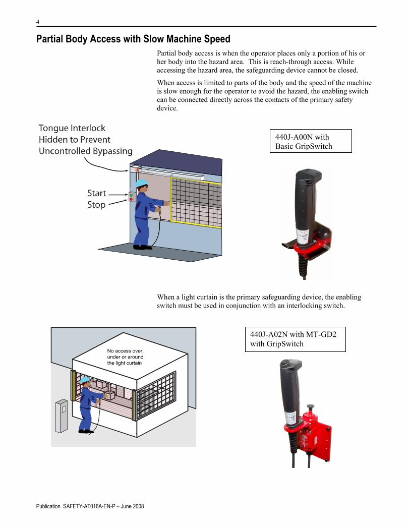
Partial Body Access with Slow Machine Speed Partial body access is when the operator places only a portion of his or her body into the hazard area. This is reach-through access. While accessing the hazard area, the safeguarding device cannot be closed.
When access is limited to parts of the body and the speed of the machine is slow enough for the operator to avoid the hazard, the enabling switch can be connected directly across the contacts of the primary safety device.
440J-A00N with Basic GripSwitch
When a light curtain is the primary safeguarding device, the enabling switch must be used in conjunction with an interlocking switch.
440J-A02N with MT-GD2 with GripSwitch
No access over,under or aroundthe light curtain

5
Publication SAFETY-AT016A-EN-P-June 2008
Application 1: Substituting a GripSwitch for a Tongue Interlock Safeguard In this first application, the GripSwitch is used in place of a tongue
interlock as the safeguarding device. With partial body access, the operator has control of the access area, so that additional operators cannot access the hazard. The operator must have access to the Start button. After opening the guard, the operator engages the trigger switch to energize the safety relay. The operator then presses the machine Start button to energize the hazard (the motor in the schematic).
Example Bill of Material
This application example uses these components.
Part Number Description Quantity 440K-T11384 Trojan T15 GD2, 2 N.C. contacts, 4 Pin M12
Quick Disconnect 1
889D-F4AC-2 Cable, 4 wire, M12 Quick Disconnect, 2m 1 440J-N21TNPM Enabling Switch 1 440J-A00N Holder for Enabling Switch 1 440R-N23132 MSR127TP Monitoring Safety Relay, Automatic
Reset, 2 N.C. Safety Inputs, 3 N.O. Safety Outputs, 1 N.C. Auxiliary Output
1
100S-C09DJ14BC Contactor, 9A, 24V DC Coil with Diode, 3 N.O. Main Contacts, 1 N.O. + 4 N.C. Auxiliary Bifurcated Contacts
2
800FM-F301
Start Button, Green, Flush Operator, “START” Legend, Metal Body
1
800F-MX10 Metal Latch, 1 N.O. Contact 1 800FM-E402
Stop Button, Red, Extended Operator, “STOP” Legend, Metal Body
1
800F-MX01 Metal Latch, 1 N.C. Contact 1

6
Publication SAFETY-AT016A-EN-P – June 2008
Setup and Wiring For detailed information on installing and wiring, refer to the product
manuals listed in the Additional Resources.
.
Ground+24V DC
CH1 CH2
MSR127TPMonitoring
SafetyRelay
Enabling Device
Reset/Monitoring
11 12
21 22
1 2
3 4
S11
S52
A1 A2
S12
23
3341 42
1324
34
14
S21
S22
S34
Tongue Interlock
Start
K1 K2
StopK1
K2
ML1
K1 K2
L2L3
.

7
Publication SAFETY-AT016A-EN-P-June 2008
Alternative Setup and Wiring - Multiple Guard Access If access is needed to multiple gates, then an enabling switch must be used for each gate. One enabling switch must not be used as a substitute for more than one interlocked gate. Although two gates allow access to the same hazard, only one Start button is allowed.
+24V DC
A1 A2
Ground
CH1 CH2
MSR127TPMonitoring
SafetyRelay
Enabling Devices
Reset/Monitoring
11 12
21 22
1 2
3 4
S11
S52
S12
23
3341 42
1324
34
14
S21
S22
S34
11 12
21 22
1 2
3 4
Tongue Interlocks
Start
K1 K2
StopK1
K2
ML1
K1 K2
L2L3

8
Publication SAFETY-AT016A-EN-P – June 2008
Alternative Setup and Wiring - Multiple Enabling Switches
If access is needed by multiple users of one gate, then multiple enabling switches must be used. All persons having to access the hazard need an enabling switch. In this case, both switches must be actuated to energize the hazard. After actuating both enabling switches, at least one operator must have access to the Start button to energize the hazard.
+24V DC
Tongue Interlock
Ground
CH1 CH2
MSR127TPMonitoring
SafetyRelay
Enabling Devices
Reset/Monitoring
1 2
3 4
S11
S52
S12
23
3341 42
1324
34
14
S21
S22
S34
11 12
21 22
1 2
3 4
Start
K1 K2
StopK1
K2
ML1
K1 K2
L2L3
A1 A2

9
Publication SAFETY-AT016A-EN-P-June 2008
Alternative Setup and Wiring – Using Enabling Switch Instead of Multiple Gates
Using the enabling device as a substitute for multiple gates is not recommended. All three guards may be accessed by only one enabling device. Although the operator holding the enabling device is protected, two other operators with no means of alternative protection, may gain access to the hazard.
Application 2: Substituting a GripSwitch for a Light Curtain Since the light curtain has OSSD outputs (both pulled up to 24V), simply substituting the light curtain with the enabling GripSwitch results in nuisance faults of the light curtain. In this case, the enabling GripSwitch is used in conjunction with a four-circuit interlock switch. The interlock switch uses two normally-closed and two normally-open contacts. An actuator tongue is mounted to the GripSwitch. When the GripSwitch is inserted into the interlock, the light curtain is active. When the GripSwitch is removed from the interlock, the light curtain is disabled and the GripSwitch is enabled.
Example Bill of Material This application example uses these components.
Part Number Description Quantity 440L-P4K1280YD 889D-F4AC-2 889D-F8AB-5
GuardShield Light Curtain, 30mm sensing, 1280mm Protective Height Mating Cable, 4 Pin, M12 Micro QD for GuardShield Transmitter, 2m. Mating Cable, 8 Pin, M12 Micro QD for GuardShield Receiver, 5m
1 1 1
440K-MT55104 889M-F12X9AE-2
MT, 2 N.C. 2 N.O., Latch Release, M23 Quick Disconnect Mating Cable, M23 Quick Disconnect, 12 pin with 9 wires, 2m
1 1
440J-N21TNPM 440J-A01N 440J-A02N
Enabling Switch, 2 N.C. Safety, 1 N.C. Aux. Right Angle Mounting Plate for One Actuator Mounting Plate, Flat, Square
1 1 1
440R-N23132 MSR127TP Monitoring Safety Relay, Automatic Reset, 2 N.C. Safety Inputs, 3 N.O. Safety Outputs, 1 N.C. Auxiliary Output.
1
100S-C09DJ14BC Contactor, 9A, 24V DC Coil with Diode, 3 N.O. Main Contacts, 1 N.O. + 4 N.C. Auxiliary Bifurcated Contacts
2
800FM-F301 800F-MX10
Start Button, Green, Flush Operator, “START” Legend, Metal Body Metal Latch, 1 N.O. Contact
1 1
800FM-E402 800F-MX01
Stop Button, Red, Extended Operator, “STOP” Legend, Metal Body Metal Latch, 1 N.C. Contact
1 1

10
Publication SAFETY-AT016A-EN-P – June 2008
Setup and Wiring For detailed information on installing and wiring, refer to the product
manuals listed in the Additional Resources.
GuardShieldSender Receiver
Brown
Blue Blue
Brown
Gnd
MT-GD2
1211
21
6
5
23
21 2233 34
43 44
Gray(OSSD1)
Pink(OSSD2)
+24V DC
Enabling Device
1 2
3 4
CH1 CH2
Reset/Monitoring
S52
S12
23
3341 42
1324
34
14
S21
A1 A2
S22
S34
Start
K1 K2
StopK1
K2
ML1
K1 K2
L2L3
MSR127TPMonitoring
SafetyRelay
. .

11
Publication SAFETY-AT016A-EN-P-June 2008
Application 3: Substituting a GripSwitch for a Guardlocking Interlock In some applications, stopping the machine in the middle of a cycle must be prevented. A guardlocking interlock may be used to accomplish this task.
The guard-locking function must be released. Then the enabling switch can be used as a substitute for the interlock contacts.
Example Bill of Material This application example uses these components.
Part Number Description Quantity 440G-MT47049 889M-F12X9AE-2
Trojan T15 GD2, 2 N.C. contacts, 4 Pin M12 Quick Disconnect Cable, M23 Quick Disconnect, 12 PIN, 9 Wire, 2m
1 1
440J-N21TNPM 440J-A00N
Enabling Switch Holder for Enabling Switch
1 1
440R-N23132 MSR127TP Monitoring Safety Relay, Automatic Reset, 2 N.C. Safety Inputs, 3 N.O. Safety Outputs, 1 N.C. Auxiliary Output
1
100S-C09DJ14BC Contactor, 9A, 24V DC Coil with Diode, 3 N.O. Main Contacts, 1 N.O. + 4 N.C. Auxiliary Bifurcated Contacts
2
800FM-F301 800F-MX10
Start Button, Green, Flush Operator, “START” Legend, Metal Body Metal Latch, 1 N.O. Contact
1 1
800FM-E402 800F-MX01
Stop Button, Red, Extended Operator, “STOP” Legend, Metal Body Metal Latch, 1 N.C. Contact
1 1

12
Publication SAFETY-AT016A-EN-P – June 2008
Setup and Wiring
For detailed information on installing and wiring, refer to the product manuals listed in the Additional Resources.
Ground+24V DC
CH1 CH2
MSR127TPMonitoring
SafetyRelay
Enabling Device
Reset/Monitoring
1 2
3 4
S11
S52
A1 A2
S12
23
3341 42
1324
34
14
S21
S22
S34
Solenoid GuardlockingTongue Interlock
Start
K1 K2
StopK1
K2
ML1
K1 K2
L2L3
MachineControlled
LockRelease
11 12
21
33 34
43 44
22
. .

13
Publication SAFETY-AT016A-EN-P-June 2008
Full Body Access with Slow Machine Speed With full body access, the safety system must utilize manual reset. This reset may or may not be a monitored reset. Additional contacts are needed when the GripSwitch is used. Using dual interlocks with four contacts each is the preferred solution for the enabling switch holder. The GripSwitch has an additional pushbutton to energize the hazard.
Dual Interlock GripSwitch Holder
440J-A04N MT-GD2 GripSwitch
14
Publication SAFETY-AT016A-EN-P – June 2008
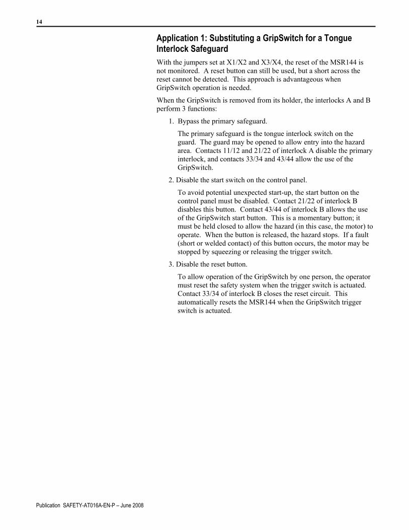
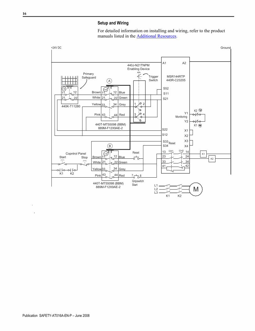
Application 1: Substituting a GripSwitch for a Tongue Interlock Safeguard With the jumpers set at X1/X2 and X3/X4, the reset of the MSR144 is
not monitored. A reset button can still be used, but a short across the reset cannot be detected. This approach is advantageous when GripSwitch operation is needed.
When the GripSwitch is removed from its holder, the interlocks A and B perform 3 functions:
1. Bypass the primary safeguard.
The primary safeguard is the tongue interlock switch on the guard. The guard may be opened to allow entry into the hazard area. Contacts 11/12 and 21/22 of interlock A disable the primary interlock, and contacts 33/34 and 43/44 allow the use of the GripSwitch.
2. Disable the start switch on the control panel.
To avoid potential unexpected start-up, the start button on the control panel must be disabled. Contact 21/22 of interlock B disables this button. Contact 43/44 of interlock B allows the use of the GripSwitch start button. This is a momentary button; it must be held closed to allow the hazard (in this case, the motor) to operate. When the button is released, the hazard stops. If a fault (short or welded contact) of this button occurs, the motor may be stopped by squeezing or releasing the trigger switch.
3. Disable the reset button.
To allow operation of the GripSwitch by one person, the operator must reset the safety system when the trigger switch is actuated. Contact 33/34 of interlock B closes the reset circuit. This automatically resets the MSR144 when the GripSwitch trigger switch is actuated.

15
Publication SAFETY-AT016A-EN-P-June 2008
Example Bill of Material This application example uses these components.
Part Number Description Quantity 440K-T11280 Primary Interlock. Trojan T15 1 440K-MT55104 440K-MT55098 889M-F12X9AE-2
Interlock A, MT-GT2, 2 N.C., 2 N.O., Latch Release, M23 QD Interlock B, MT-GD2, 2 N.C., 2 N.O., No Latch Release, M23 QD Mating Cable, M23 Quick Disconnect, 12 pin with 9 wires, 2m
1 1 2
440J-N21TNPM-NE 440J-A03N 440J-A04N
Enabling Switch with Auxiliary Button Mounting Plate for Two Actuators U-Shaped Mounting Bracket
1 1 1
440R-C23205 MSR144RTP Safety Relay. This relay accepts the MSR230 and MSR238 expansion modules for additional safety outputs. The MSR144RTP can be directly replaced with MSR131 and MSR142 relays with no wiring changes.
1
100S-C09DJ14BC Contactor, 9A, 24V DC Coil with Diode, 3 N.O. Main Contacts, 1 N.O. + 4 N.C. Auxiliary Bifurcated Contacts
2
800FM-F301 800F-MX10
Start Button, Green, Flush Operator, “START” Legend, Metal Body Metal Latch, 1 N.O. Contact
1 1
800FM-E402 800F-MX01
Stop Button, Red, Extended Operator, “STOP” Legend, Metal Body Metal Latch, 1 N.C. Contact
1 1
800FM-F6 800F-MX10
Reset Button, Blue, Flush Operator, Metal Body Metal Latch, 1 N.O. contact
1
16
Publication SAFETY-AT016A-EN-P – June 2008
Setup and Wiring
For detailed information on installing and wiring, refer to the product manuals listed in the Additional Resources.
StartCopntrol Panel
K1 K2
Stop
Ground+24V DC
CH1 CH2
MSR144RTP440R-C23205
440J-N21TNPMEnabling Device
K2
K1
7 8
Reset
GripswitchStart
Reset
Monitoring
440K-T11280
11 12
21 22
11 12
21 22
33 34
43 44
1 2
3 4
S11
S52
A1 A2
S12
23
3341 42
1324
34
14
S33
S21
S22
S34
Y1
Y2
X3
X4
X1
X2
440T-MT55098 (BBM)889M-F12X9AE-2
Brown
White
Yellow
Pink
Blue
Green
Grey
Red
K2
K1
ML1
K1 K2
L2L3
440T-MT55098 (BBM)889M-F12X9AE-2
11 12
21 22
33 34
43 44
Brown
White
Yellow
Pink
Blue
Green
Grey
Red
A
B
TriggerSwitch
PrimarySafeguard
. .

17
Publication SAFETY-AT016A-EN-P-June 2008
Application 2: Substituting a GripSwitch for a Light Curtain With full body access, the GuardShield Perimeter Access Control PAC safety light curtain may be used as the primary safeguard.
With the jumpers set at X1/X2 and X3/X4, the reset of the MSR144 is not monitored. A reset button may still be used but a short (fault) across the reset cannot be detected. This approach is advantageous when a GripSwitch operation is needed.
When the GripSwitch is removed from its holder, interlocks A and B perform 3 functions:
1. Substitute the GripSwitch for the primary safeguard.
The primary safeguard is the light curtain. The operator can walk through the light curtain to gain access to the hazard area. Contact 11/12 and 21/22 of interlock A disable the light curtain, and contact 33/34 and 43/44 allow the use of the GripSwitch.
2. Disable the Start switch on the control panel.
To avoid potential unexpected start-up, the Start button on the control panel must be disabled. Contact 21/22 of interlock B disables this button. Contact 43/44 of interlock B allows the use of the GripSwitch Start button. This GripSwitch button is momentary; it must be held closed to allow the hazard (for example, the motor) to operate. When the button is released, the hazard stops. If a fault (short or welded contact) of this button occurs, the motor can be stopped by squeezing or releasing the trigger switch.
3. Disable the reset button.
To allow operation of the GripSwitch by one person, the safety system must be reset when the trigger switch is actuated. Contact 33/34 of interlock B closes the reset circuit. This automatically resets the MSR144 when the GripSwitch trigger switch is actuated.

18 Example Bill of Material
This application example uses these components.
Part Number Description Quantity 440L-P4A3400YD 889D-F4AC-2 889D-F8AB-5
GuardShield PAC, 3 Beam Sensing, 800mm Protective Height Mating Cable, 4 Pin, M12 Micro QD for GuardShield Transmitter, 2m Mating Cable, 8 Pin, M12 Micro QD for GuardShield Receiver, 5m
1 1 1
440K-MT55104 440K-MT55098 889M-F12X9AE-2
Interlock A, MT-GT2, 2 N.C., 2 N.O., Latch Release, M23 QD Interlock B, MT-GD2, 2 N.C., 2 N.O., No Latch Release, M23 QD Mating Cable, M23 Quick Disconnect, 12 pin with 9 wires, 2m
1 1 2
440J-N21TNPM-NP 440J-A03N 440J-A04N
Enabling Switch with Jog Button Mounting Plate for Two Actuators U-Shaped Mounting Bracket
1 1 1
440R-C23205 MSR144RTP Safety Relay. This relay accepts the MSR230 and MSR238 expansion modules for additional safety outputs. The MSR144RTP can be directly replaced with MSR131 and MSR142 relays with no wiring changes.
1
100S-C09DJ14BC Contactor, 9A, 24V DC Coil with Diode, 3 N.O. Main Contacts, 1 N.O. + 4 N.C. Auxiliary Bifurcated Contacts
2
800FM-F301 800F-MX10
Start Button, Green, Flush Operator, “START” Legend, Metal Body Metal Latch, 1 N.O. Contact
1 1
800FM-E402 800F-MX01
Stop Button, Red, Extended Operator, “STOP” Legend, Metal Body Metal Latch, 1 N.C. Contact
1 1
800FM-F6 800F-MX10
Reset Button, Blue, Flush Operator, Metal Body Metal Latch, 1 N.O. contact
1
Setup and Wiring
For detailed information on installing and wiring, refer to the product manuals listed in the Additional Resources.
Publication SAFETY-AT01
6A-EN-P – June 2008
StartCopntrol Panel
K1 K2
Stop
Ground+24V DC
CH1 CH2
MSR144RTPMinotaurSafetyRelay
440J-N21TNPMEnabling Device
K2
K1
7 8
Reset
GripswitchStart
Reset
Monitoring
S52
A1 A2
S12
23
3341 42
1324
34
14
S33
S21
S22
S34
Y1
Y2
11 12
21 22
33 34
43 44
1 2
3 4
X3X4
X1X2
Brown
White
Yellow
Pink
Blue
Green
Grey
Red
K2
K1
ML1
K1 K2
L2L3
11 12
21 22
33 34
43 44
Brown
White
Yellow
Pink
Blue
Green
Grey
Red
ATriggerSwitch
PrimarySafeguard
GuardShield PACSender Receiver
Brown
B
Blue Blue
Brown21
6
5
23
Gray(OSSD1)
Pink(OSSD2)
MT-GD2 withLatch Release
MT-GD2

19
Publication SAFETY-AT016A-EN-P-June 2008
Additional Resources For more information about the products used in this example refer to these Resources.
Resource Description
Trojan T 15 Installation Instructions, publication 91595/1
Provides installation instructions for the Trojan T15
Safety Catalog, publication S116-CA001A-EN-P
Provides detailed product information and specifications
GuardShield Safety Light Curtain Installation Instructions, publication 75035-270-01(F)
Installations instructions for the GuardShield Safety Light Curtain
You can view or download publications at http://literature.rockwellautomation.com. To order paper copies of technical documentation, contact your local Rockwell Automation distributor or sales representative.

20
Publication SAFETY-AT016A-EN-P – June 2008
Allen-Bradley, Rockwell Automation, and GuardShield are trademarks of Rockwell Automation, Inc. Trademarks not belonging to Rockwell Automation are property of their respective companies.
Publication SAFETY-AT016A-EN-P – June 2008 Copyright © 2008 Rockwell Automation, Inc. All rights reserved. Printed in U.SA