Embed Size (px)
Citation preview

SAFETY SERIES No. 118
Safety Assessment forSpent FuelStorage Facilities
INTERNATIONAL ATOMIC ENERGY AGENCY, VIENNA, 1994
This publication is no longer valid Please see http://www-ns.iaea.org/standards/
CATEGORIES IN THE IAEA SAFETY SERIES
A new hierarchical categorization scheme has been introduced, according towhich the publications in the IAEA Safety Series are grouped as follows:
Safety Fundamentals (silver cover)
Basic objectives, concepts and principles to ensure safety.
Safety Standards (red cover)
Basic requirements which must be satisfied to ensure safety for particularactivities or application areas.
Safety Guides (green cover)
Recommendations, on the basis of international experience, relating to the ful-filment of basic requirements.
Safety Practices (blue cover)
Practical examples and detailed methods which can be used for the applicationof Safety Standards or Safety Guides.
Safety Fundamentals and Safety Standards are issued with the approval of theIAEA Board of Governors; Safety Guides and Safety Practices are issued under theauthority of the Director General of the IAEA.
An additional category, Safety Reports (purple cover), comprises independentreports of expert groups on safety matters, including the development of new princi-ples, advanced concepts and major issues and events. These reports are issued underthe authority of the Director General of the IAEA.
There are other publications of the IAEA which also contain informationimportant to safety, in particular in the Proceedings Series (papers presented atsymposia and conferences), the Technical Reports Series (emphasis on technologicalaspects) and the IAEA-TECDOC Series (information usually in a preliminary form).
This publication is no longer valid Please see http://www-ns.iaea.org/standards/

This publication is no longer valid Please see http://www-ns.iaea.org/standards/

This publication is no longer valid Please see http://www-ns.iaea.org/standards/

SAFETY ASSESSMENT FORSPENT FUEL STORAGE FACILITIES
This publication is no longer valid Please see http://www-ns.iaea.org/standards/
The following States are Members of the International Atomic Energy Agency:
ICELAND PERU
INDIA PHILIPPINES
AFGHANISTAN
ALBANIA
ALGERIA
ARGENTINA
ARMENIA
AUSTRALIA
AUSTRIA
BANGLADESH
BELARUS
BELGIUM
BOLIVIA
BRAZIL
BULGARIA
CAMBODIA
CAMEROON
CANADACHILE
CHINACOLOMBIA
COSTA RICA
COTE D'lVOIRE
CROATIA
CUBA
CYPRUS
CZECH REPUBLIC
DENMARK
DOMINICAN REPUBLIC
ECUADOR
EGYPT
EL SALVADOR
ESTONIA
ETHIOPIA
FINLAND
FRANCE
GABON
GERMANY
GHANA
GREECE
GUATEMALA
HAITI
HOLY SEE
HUNGARY
INDONESIAIRAN,
11. ISLAMIC REPUBLIC OFIRAQ
IRELAND
ISRAEL
ITALY
IAMAICA
JAPAN
JORDAN
KAZAKHSTANKENYA
KOREA, REPUBLIC OF
KUWAITLEBANON
LIBERIA
LIBYAN ARAB JAMAHIRIYA
LIECHTENSTEIN
LITHUANIA
LUXEMBOURG
MADAGASCAR
MALAYSIAMALI
MARSHALL ISLANDS
MAURITIUSMEXICO
MONACO
MONGOLIA
MOROCCO
MYANMAR
NAMIBIA
NETHERLANDS
NEW ZEALAND
NICARAGUA
NIGER
NIGERIA
NORWAY
PAKISTAN
PANAMA
PARAGUAY
POLAND
PORTUGAL
QATAR
ROMANIA
RUSSIAN FEDERATION
SAUDI ARABIA
SENEGAL
SIERRA LEONE
SINGAPORE
SLOVAKIA
SLOVENIA
SOUTH AFRICA
SPAIN
SRI LANKASUDAN
SWEDEN
SWITZERLAND
SYRIAN ARAB REPUBLIC
THAILAND
THE FORMER YUGOSLAV
REPUBLIC OF MACEDONIA
TUNISIA
TURKEY
UGANDA
UKRAINE
UNITED ARAB EMIRATES
UNITED KINGDOM OF
GREAT BRITAIN AND
NORTHERN IRELAND
UNITED REPUBLIC OF TANZANIA
UNITED STATES OF AMERICA
URUGUAY
UZBEKISTAN
VENEZUELA
VIET NAM
YEMEN
YUGOSLAVIA
ZAIRE
ZAMBIA
ZIMBABWE
The Agency's Statute was approved on 23 October 1956 by the Conference on the Statute of theIAEA held at United Nations Headquarters, New York; it entered into force on 29 July 1957. The Head-quarters of the Agency are situated in Vienna. Its principal objective is "to accelerate and enlarge thecontribution of atomic energy to peace, health and prosperity throughout the world".
© IAEA, 1994
Permission to reproduce or translate the information contained in this publication may beobtained by writing to the International Atomic Energy Agency, Wagramerstrasse 5, P.O. Box 100,A-1400 Vienna, Austria.
Printed by the IAEA in AustriaDecember 1994STI/PUB/981
This publication is no longer valid Please see http://www-ns.iaea.org/standards/

SAFETY SERIES No. 118
SAFETY ASSESSMENT FORSPENT FUEL STORAGE FACILITIES
INTERNATIONAL ATOMIC ENERGY AGENCYVIENNA, 1994
This publication is no longer valid Please see http://www-ns.iaea.org/standards/
VIC Library Cataloguing in Publication Data
Safety assessment for spent fuel storage facilities. — Vienna : InternationalAtomic Energy Agency, 1994.
p. ; 24 cm. - (Safety series, ISSN 0074-1892 ; 118)STI/PUB/981ISBN 92-0-105194-8Includes bibliographical references.
1. Spent reactor fuels—Storage—Safety measures. I. InternationalAtomic Energy Agency. II. Series.
VICL 95-00113
This publication is no longer valid Please see http://www-ns.iaea.org/standards/
FOREWORD
The spent fuel resulting from operation of nuclear reactors to produce electri-cal energy must be safely stored and managed pending its reprocessing or disposal.The IAEA recognizes the increasing need for such interim spent fuel storage and hasconsequently established a programme to provide guidance to its Member States onthe key safety aspects of safe storage. This programme complements the IAEA'sNuclear Safety Standards (NUSS) programme.
The IAEA has prepared a series of three related Safety Series publicationsaddressing (i) the design, (ii) the operation, and (iii) the safety assessment of interimspent fuel storage facilities. This Safety Practice addresses the management of allrelevant issues concerned with the safety of the storage of spent fuel from nuclearpower plants.
This Safety Practice was developed through a series of Advisory GroupMeetings, Technical Committee Meetings and Consultants Meetings from 1991 to1994. It describes accepted international approaches for maintaining fuel subcritical,removing residual heat, providing radiation protection and containing radioactivematerials for the lifetime of the facility.
This publication is no longer valid Please see http://www-ns.iaea.org/standards/

This publication is no longer valid Please see http://www-ns.iaea.org/standards/
CONTENTS
1. INTRODUCTION 1
1.1. BACKGROUND 11.2. OBJECTIVE 11.3. SCOPE 11.4. STRUCTURE 2
2. SAFETY ASSESSMENT 2
2.1. GENERAL 22.2. GENERAL GUIDANCE 32.3. DETERMINISTIC SAFETY ANALYSIS 42.4. PROBABILISTIC SAFETY ASSESSMENT 52.5. IDENTIFICATION OF INITIATING EVENTS
AND FAULT SEQUENCES 6
3. SAFETY ASSESSMENT OF OPERATIONAL STATES 7
3.1. GENERAL 73.1.1. Fundamental requirements 73.1.2. Fuel related considerations 83.1.3. Various limiting parameters 8
3.2. SITE CONDITIONS, PROCESSES AND EVENTS 103.3. STRUCTURAL INTEGRITY 11
3.3.1. Structural and mechanical loads 123.3.2. Thermal loads and processes 123.3.3. Time dependent material processes 12
3.4. PERFORMANCE OF SAFETY RELATED SYSTEMSAND COMPONENTS 13
3.5. ASSURANCE OF A SUBCRITICAL STATE 133.5.1. Assessing subcriticality: General questions of wet
and dry storage 133.5.2. Assessing subcriticality: Specifics for wet storage 153.5.3. Assessing subcriticality: Specifics for dry storage 15
3.6. REMOVAL OF DECAY HEAT 163.6.1. Heat removal: General questions of wet
and dry storage 163.6.2. Heat removal: Specifics for wet storage 163.6.3. Heat removal: Specifics for dry storage 17
This publication is no longer valid Please see http://www-ns.iaea.org/standards/
3.7. RADIOLOGICAL PROTECTION 183.7.1. Radiological protection: General questions of wet
and dry storage 183.7.2. Radiological protection: Specifics for wet storage 193.7.3. Radiological protection: Specifics for dry storage 20
3.8. MONITORING 21
4. SAFETY ASSESSMENT OF ACCIDENTS 22
4.1. GENERAL 224.2. MAINTENANCE OF A SUBCRITICAL STATE 22
4.2.1. Assessing subcriticality: Wet storage 224.2.2. Assessing subcriticality: Dry storage 23
4.3. REMOVAL OF DECAY HEAT 234.3.1. Heat removal: Wet storage 234.3.2. Heat removal: Dry storage 23
4.4. RADIOLOGICAL PROTECTION 244.4.1. Radiological protection: Wet storage 244.4.2. Radiological protection: Dry storage 25
4.5. MISCELLANEOUS ASSESSMENTS 254.5.1. Seismic event 254.5.2. High winds 264.5.3. Fire and explosion 264.5.4. Aircraft crash, missiles, flying debris 274.5.5. Dropping of a fuel container or other heavy loads 274.5.6. Flood 284.5.7. Loss of electric power 28
5. SAFETY ANALYSIS REPORT 28
5.1. PURPOSE OF A SAFETY ANALYSIS REPORT 285.2. CONTENTS OF A SAFETY ANALYSIS REPORT 295.3. STAGED LICENSING 315.4. TIME LIMITATIONS 31
ANNEX: Contents of a Safety Analysis Report 33
DEFINITIONS 41
REFERENCES 47
BIBLIOGRAPHY 47
This publication is no longer valid Please see http://www-ns.iaea.org/standards/

CONTRIBUTORS TO DRAFTING AND REVIEW 53
LIST OF NUSS PROGRAMME TITLES 57
SELECTION OF IAEA PUBLICATIONS RELATING TOTHE SAFETY OF NUCLEAR POWER PLANTS 61
This publication is no longer valid Please see http://www-ns.iaea.org/standards/

This publication is no longer valid Please see http://www-ns.iaea.org/standards/

1. INTRODUCTION
1.1. BACKGROUND
This Safety Practice has been prepared as part of the IAEA's programme onthe safety of spent fuel storage. It reflects the standards of the IAEA NUSSprogramme related to nuclear power plants and is a companion publication to twoSafety Guides which treat the subject of spent fuel storage at interim spent fuelstorage facilities, namely, Design of Spent Fuel Storage Facilities [1] and Operationof Spent Fuel Storage Facilities [2].
1.2. OBJECTIVE
The purpose of this Safety Practice is to provide details on how to assess anddocument the safety of a spent fuel storage facility.
1.3. SCOPE
This Safety Practice is primarily intended to provide details on the safetyassessment of interim spent fuel storage facilities that are not an integral part of anoperating nuclear power plant. Such an interim storage facility may be either co-located with other nuclear facilities (such as a nuclear power plant or reprocessingplant) or sited independently.
If the spent fuel storage facility is an integral part of an operating nuclearpower plant, there will be additional considerations not dealt with in this SafetyPractice but which can be found in the Safety Guide on Fuel Handling and StorageSystems in Nuclear Power Plants [3]. Similarly, publications on the design of highlevel waste and spent fuel disposal facilities are included in the Radioactive WasteSafety Standards (RADWASS) series.
The type of spent fuel considered in this Safety Practice is typically that derivedfrom water moderated reactors. This Safety Practice can also be applied to other fueltypes such as those from gas cooled reactors, as well as fuel assembly components.Some items, such as canistered failed fuel, may also be considered if an adequatesafety analysis is prepared.
Transport requirements are provided in IAEA Regulations for the SafeTransport of Radioactive Materials [4], and in related IAEA publications (e.g. theTECDOC entitled Interfaces between Transport and Geological Disposal Systemsfor High Level Waste and Spent Nuclear Fuel [5]). The interface between storageand transport is discussed in this Safety Practice.
1
This publication is no longer valid Please see http://www-ns.iaea.org/standards/
1.4. STRUCTURE
This Safety Practice has five sections. Following this Introduction, Section 2provides general guidance on the safety assessment process, discussing both deter-ministic and probabilistic assessment methods. This section may be used to identifythose events and sequences which need to be analysed and the appropriate analysismethod to be used.
Section 3 describes the safety assessment process for normal operation andanticipated operational occurrences. Guidance is provided on how to categorize theseoperational states and determine the appropriate design requirements.
Section 4 describes the safety assessment process as it relates to accidentconditions. The discussion covers both design basis accidents and those consideredbeyond design basis.
Section 5 describes the purpose and contents of the Safety Analysis Report andits relationship to the licensing process.
The Annex contains an example of a Safety Analysis Report, and the Bibliogra-phy suggests some useful reading.
2. SAFETY ASSESSMENT
2.1. GENERAL
Interim spent fuel storage facilities are required for the safe, stable and securestorage of spent nuclear fuel after it has been removed from the reactor pool andbefore it is reprocessed or disposed of as radioactive waste.
Various designs of wet and dry storage facilities are in operation or underconsideration in Member States. Although designs differ, all consist of relativelysimple, often passive systems, which are intended to provide adequate safety overseveral decades. Associated handling and storage operations are relativelystraightforward.
Spent fuel is usually transferred to interim spent fuel storage facilities onlyafter an initial period of storage at the reactor station. This initial period of storageallows a considerable reduction in the quantity of volatile radionuclides, the radiationfields and the production of decay heat. Hence, the development of conditions whichcould lead to accidents in interim spent fuel storage facilities will generally occurcomparatively slowly, allowing ample time for corrective action before limitingconditions may be approached. The safety of spent fuel handling and storageoperations can thus be maintained without reliance on complex, automaticallyinitiated protective systems.
This publication is no longer valid Please see http://www-ns.iaea.org/standards/
The safe operation and maintenance of spent fuel storage facilities, as withother engineered systems, depends in part on adequate design and construction. Themost important design features of such facilities are those which provide thenecessary assurances that spent fuel can be received, handled, stored and retrievedwithout undue risk to health and safety, or to the environment.
To achieve these objectives, the design of spent fuel storage facilities mustincorporate features to maintain fuel subcritical, to remove spent fuel decay heat, toprovide for radiation protection, and to maintain containment over the anticipatedlifetime of the facilities as specified in the design specifications. These objectivesmust be met in all anticipated operational occurrences and design basis accidents inaccordance with the design basis as approved by the Regulatory Body. The mostimportant purpose of the Safety Analysis Report (SAR) is to show that these require-ments have been fulfilled.
The Regulatory Body is responsible for establishing basic safety criteria. Thecompetent authorities in the Member States approach this task in different ways andto varying degrees of detail. The criteria reflect the judgement of the RegulatoryBody regarding what is required to protect the public and the operating personnelfrom radiological and other hazards. The IAEA's International Basic SafetyStandards for Protection Against Ionizing Radiation and for the Safety of RadiationSources [6] gives guidance on this topic and should be consulted.
Safe operation of a facility is the responsibility of the operating organization.Demonstration of safety, both during the operating lifetime of a facility and prior tooperation, is also the responsibility of the operating organization. Therefore theorganization must provide an SAR that demonstrates the adequacy of the design inmeeting specified safety criteria.
2.2. GENERAL GUIDANCE
The allocation of specific safety analyses to either operational states (as dis-cussed in Section 3) or accidents (as discussed in Section 4) is somewhat arbitrary.The fundamental distinction rests upon the recognition that anticipated operationaloccurrences have a sufficiently high probability of occurrence that they may be con-sidered operational in nature, whereas accident conditions have a lower probabilityof occurrence.
Similarly, the distinction between accident conditions and severe accidents isan arbitrary one based upon consideration of the probabilities of occurrence and theconsequences. It is very site dependent. The distinctions are illustrated by the figurein the Definitions Section.
Design basis accidents, as the name implies, must be addressed in the design.Severe accidents fall into two general groups: those which have a high enough
This publication is no longer valid Please see http://www-ns.iaea.org/standards/

probability of occurrence and severe enough consequences that some prior consider-ation of possible corrective or remedial actions is advisable; and those which havea low enough probability of occurrence for such consideration to be ignored.
There is a reciprocity between safety assessment and engineering designinasmuch as safety assessment both influences, and is influenced by, the engineeringdesign. Safety assessment should therefore begin with a description and explanationof certain choices made by the designer which guide, limit or bound the resultingdesign.
Safety assessments make use of deterministic and probabilistic methods.Frequently, the design is based on the assessment of a given list of initiating faultconditions using certain deterministic criteria (e.g. application of the single failurecriterion) to show that certain limits (e.g. fuel or material temperatures, structuralstress levels) are satisfied. This may be complemented by a probabilistic safetyassessment to confirm that an adequate overall level of safety has been achievedand that the balance of the design in terms of protection against different faults isreasonable.
A safety analysis should take the form of a deterministic demonstrationwhenever possible. This demonstration results in a safety margin being expressed interms of the difference between the calculated value and the declared safety limit fora specific parameter. It follows that the data selected for a deterministic analysisshould be conservative.
Probabilistic work is best applied to support deterministic analyses bydemonstrating the frequency of breaching a known safety limit. In general, thiswork will require estimates to be made of the consequence as well as the probabilityof failure. The estimates result in a safety margin being expressed as a percentageof the risk or frequency target that is declared to be acceptable. To avoidcompounding pessimism, it is normal practice to use best estimate parameters forprobabilistic work.
It is also well known that probabilistic analyses need to make adequateallowance for the effects of human error and common cause failure if the results areto have credence.
In all aspects of the safety analysis, calculations should make use of verifiedor validated calculational methods and data, as appropriate. The source of all dataused should be identified. All codes and standards used should be referenced.
The advice which follows is meant to address both wet and dry storage of spentfuel and all points raised should therefore be considered where applicable.
2.3. DETERMINISTIC SAFETY ANALYSIS
Certain parameters may be chosen at the discretion of the designer, or bedictated by material properties and physical or chemical constraints, or mandated
This publication is no longer valid Please see http://www-ns.iaea.org/standards/

directly or indirectly by the Regulatory Body. Some of these parameters will havea limiting, bounding or guiding influence on the design. The SAR should identifyand explain all such parameters. Each discussion should include a justification of allchoices with appropriate data, analyses and reasoned argument.
The objective is to store spent fuel safely. Therefore, a detailed description ofthe spent fuel to be stored should be provided. This description should characterizethe fuel with respect to its nature, amount and the anticipated storage time. Thecharacterization requires calculation of isotopic inventories which, in turn, are usedto determine compliance with specific limits that have been established for storageat the facility. Different parameters might be selected, i.e. maximum irradiation andminimum cooling for shielding design, radiological protection and heat generationrate calculations, but zero irradiation and maximum initial enrichment for subcriti-cality calculations, unless credit for burnup is taken.
The analysis needs to provide justification (i.e. from reactor records, physicalchecks and measurements, management systems) for the choice of limiting fuelparameters. Justification should also be provided for assuming that the fuel sent tothe facility will be within acceptable limits. The method for identifying any fuelwhich is not within acceptable limits and the procedures to be followed in thateventuality should also be explained and justified.
2.4. PROBABILISTIC SAFETY ASSESSMENT
To carry out a probabilistic safety assessment:
— Each initiating event or sequence of events which could lead to developmentof a fault condition should be identified;
— The fault scenarios or sequences leading to the postulated fault conditionshould be defined in detail;
— The probabilities that the various postulated fault conditions will occur shouldbe determined;
— If necessary, the consequences of the various postulated fault conditionswith particular reference to the three safety related issues of maintainingsubcriticality, heat removal and radiological protection should be assessed;
— The resulting risk or probability of occurrence should be compared with acriterion of acceptability.
When the probability of occurrence is less than unity and/or the consequenceis expressed in probabilistic terms, the SAR becomes one based upon risk (using riskin its technical sense as the probability of occurrence, multiplied by the consequence)and is sometimes referred to as a probabilistic safety assessment (PSA) or probabilis-tic risk assessment (PRA).
This publication is no longer valid Please see http://www-ns.iaea.org/standards/
Techniques for estimating the probability of occurrence are well known andthere is much guidance available. The main technique is fault tree analysis (FTA)supported, if necessary, by other techniques, of which perhaps failure mode andeffects analysis (FMEA) is the most useful. Event trees may also be used.
FTA has several important benefits and, in particular, it can handle threespecific aspects of fault analysis successfully. These are:
— Complex logic;— The effect of human error;— Common cause effects.
2.5. IDENTIFICATION OF INITIATING EVENTS AND FAULT SEQUENCES
Before considering each of the safety related technical issues in turn, it isnecessary to establish a listing of initiating faults via such methods as creation of faultschedules, information generated by structured design and safety review exercisessuch as hazard and operability studies (HAZOPS), and the experience of theassessor.
It is necessary to recall that much of the input required here will derive fromsite and facility specific considerations. Tables I and II in Section 3.2 list examplesof natural phenomena and external man-induced phenomena which should beconsidered in this context.
Faults may be due to environmental extremes, equipment failure, humanactivities (including operator error) or some combination of all of these. Examplesof faults which can be analysed (as they pertain to particular systems) are:
— Receipt of defective fuel;— Receipt of out-of-specification fuel;— Incorrect loading of fuel;— Fuel handling faults (dropped loads, impacts);— System faults (e.g. heating and ventilation);— Loss of external electrical supplies;— Faults in heat removal system;— Flow blockages;— Faults in coolant or pool water circulation systems;— Faults in coolant or pool water composition;— Excessive coolant or pool water leakage;— Faults in containment (e.g. container leakage);— Structural failures (e.g. failure of baskets, fuel racks);— Flood/high winds/seismic events/aircraft crash;— Fire;— Explosion;— Failure to maintain intended fuel environment;— Leakage from radioactive waste systems.
This publication is no longer valid Please see http://www-ns.iaea.org/standards/
A schedule of faults should be prepared, and for each fault (or group of faultshaving common characteristics) the procedures and/or engineered safety systems(if any) which will be used should be listed. The fault studies will assess the transientdevelopment of the faults in the fuel, coolant and structures, and any other criticalparameters (e.g. pressure within closed containments) to show whether these remainacceptable, taking account of possible actions such as corrective action or repairs ifthe time-scale is sufficiently long.
3. SAFETY ASSESSMENT OF OPERATIONAL STATES
3.1. GENERAL
The safety assessment starts with general matters as explained in Section 2 andamplified below.
3.1.1. Fundamental requirements
The SAR should explain what fundamental design requirements have beenapplied and how the resulting design reflects these requirements.
Typically, the fundamental design requirements will address such considera-tions as the need to ensure an adequate degree of redundancy, diversity and reliabil-ity, and the need to ensure that any failures which might occur are limited in scopeand to the extent possible.
It will also be expected that the design will respect the principle of defence indepth (as described in The Safety of Nuclear Installations [7] and in Basic SafetyPrinciples for Nuclear Power Plants [8]). For spent fuel storage facilities, whichare characterized by relatively simple, often passive systems and relativelystraightforward handling and storage operations, the implementation of defence indepth will generally mean the use of multiple barriers to shield against radiation andto prevent the escape of radioactive material from the fuel to the environment.
These barriers may include the fuel matrix and cladding, with appropriate notetaken of potential cladding failures and the fact that the retention of volatile materialsand particulates by the fuel matrix is a function of the temperature and environment.Further containment barriers may include the pool boundary with its auxiliary sys-tems, a container or storage tube in a vault storage facility, or the liners and othercomponents of casks and silos.
Defence in depth also requires that at all times when the fuel is being handled,adequate containment barriers are maintained.
This publication is no longer valid Please see http://www-ns.iaea.org/standards/
3.1.2. Fuel related considerations
Typical fuel related considerations to be addressed in the SAR include:
(a) Design basis fuel assemblies— Physical description (form, composition, materials, mass, etc.);— Initial enrichment;— Burnup/burnup history;— Minimum cooling period;— Isotopic composition at time of storage;— Radiation fields at time of storage;— Reactivity at time of storage;— Decay heat production.
(b) Arrangements for damaged fuel or fuel outside specifications(c) Fuel inventory
— Number of assemblies per storage unit;— Total number of assemblies.
(d) Anticipated maximum storage duration.
Isotopic characterization of individual assemblies is necessary to determineaccurately radiological and decay heat conditions. Several validated and verifiedcomputer codes are available for such characterization.
3.1.3. Various limiting parameters
The following are typical examples of parameters which may have a limiting,bounding or guiding influence on safety and, therefore, should be addressed inthe SAR:
— Design life of the storage facility;— Selection of component materials;— Fuel cladding temperature;— Material temperatures;— Radiation fields;— Pool water chemistry and radioactivity;— Gaseous and liquid releases inside the facility;— Gaseous and liquid releases outside the facility.
All choices of this kind should be justified with appropriate data, analyses andreasoned argument.
8
This publication is no longer valid Please see http://www-ns.iaea.org/standards/
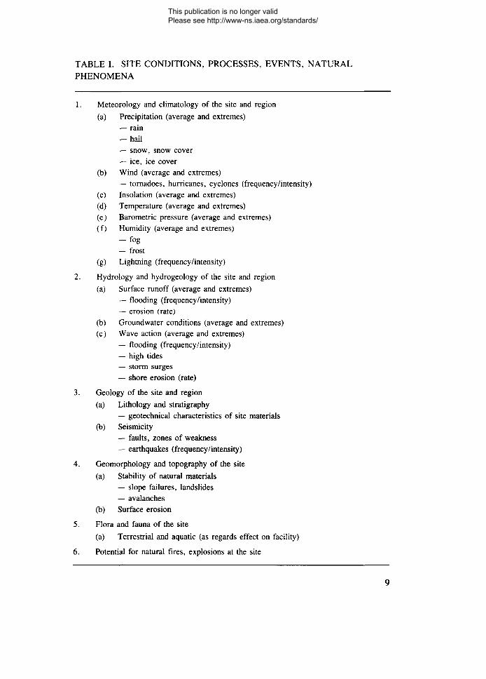
TABLE I. SITE CONDITIONS, PROCESSES, EVENTS, NATURAL
PHENOMENA
1. Meteorology and climatology of the site and region
(a) Precipitation (average and extremes)— rain-hail— snow, snow cover— ice, ice cover
(b) Wind (average and extremes)— tornadoes, hurricanes, cyclones (frequency/intensity)
(c) Insolation (average and extremes)(d) Temperature (average and extremes)(e) Barometric pressure (average and extremes)(f) Humidity (average and extremes)
— fog— frost
(g) Lightning (frequency/intensity)
2. Hydrology and hydrogeology of the site and region
(a) Surface runoff (average and extremes)— flooding (frequency/intensity)— erosion (rate)
(b) Groundwater conditions (average and extremes)(c) Wave action (average and extremes)
— flooding (frequency/intensity)— high tides— storm surges— shore erosion (rate)
3. Geology of the site and region
(a) Lithology and stratigraphy— geotechnical characteristics of site materials
(b) Seismicity— faults, zones of weakness— earthquakes (frequency/intensity)
4. Geomorphology and topography of the site
(a) Stability of natural materials— slope failures, landslides— avalanches
(b) Surface erosion
5. Flora and fauna of the site
(a) Terrestrial and aquatic (as regards effect on facility)
6. Potential for natural fires, explosions at the site
This publication is no longer valid Please see http://www-ns.iaea.org/standards/
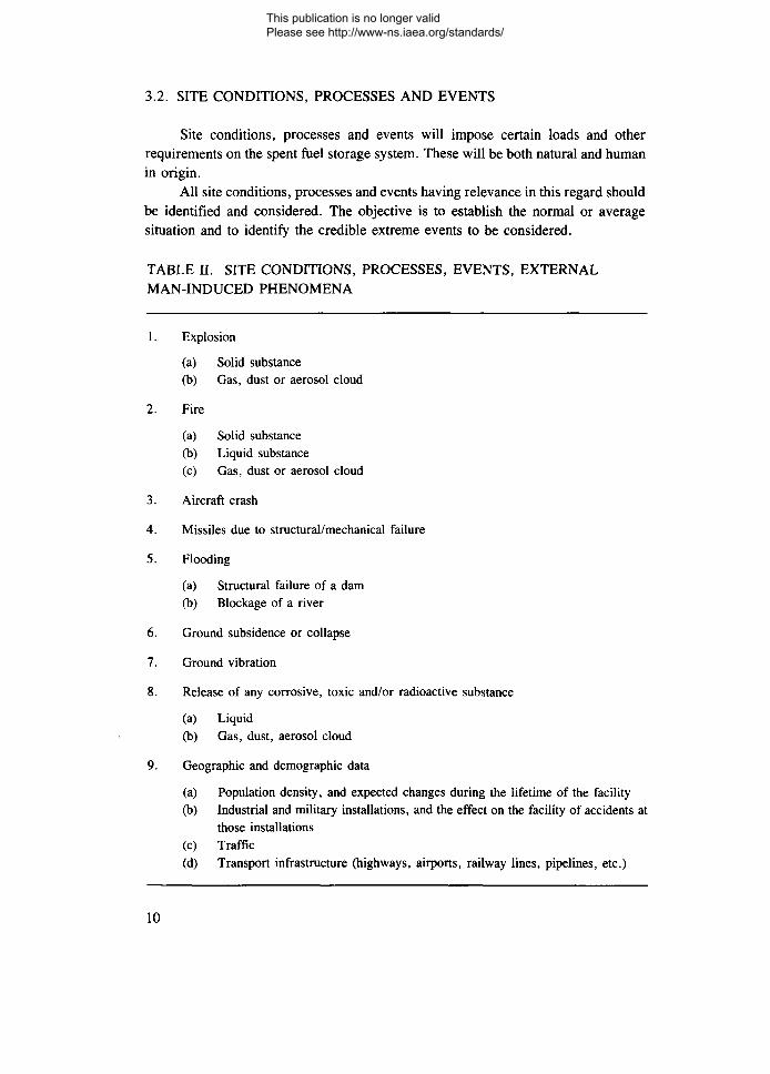
3.2. SITE CONDITIONS, PROCESSES AND EVENTS
Site conditions, processes and events will impose certain loads and otherrequirements on the spent fuel storage system. These will be both natural and humanin origin.
All site conditions, processes and events having relevance in this regard shouldbe identified and considered. The objective is to establish the normal or averagesituation and to identify the credible extreme events to be considered.
TABLE H. SITE CONDITIONS, PROCESSES, EVENTS, EXTERNALMAN-INDUCED PHENOMENA
1. Explosion
(a) Solid substance(b) Gas, dust or aerosol cloud
2. Fire
(a) Solid substance(b) Liquid substance(c) Gas, dust or aerosol cloud
3. Aircraft crash
4. Missiles due to structural/mechanical failure
5. Flooding
(a) Structural failure of a dam(b) Blockage of a river
6. Ground subsidence or collapse
7. Ground vibration
8. Release of any corrosive, toxic and/or radioactive substance
(a) Liquid(b) Gas, dust, aerosol cloud
9. Geographic and demographic data
(a) Population density, and expected changes during the lifetime of the facility(b) Industrial and military installations, and the effect on the facility of accidents at
those installations(c) Traffic(d) Transport infrastructure (highways, airports, railway lines, pipelines, etc.)
10
This publication is no longer valid Please see http://www-ns.iaea.org/standards/
The exercise is very site specific. Tables I and II, the IAEA Safety Guide onExternal Man-Induced Events in Relation to Nuclear Power Plant Design [9] and theAnnex of this Safety Practice all contain lists which the designer may wish to consultwhen identifying the site conditions, processes and events that are relevant to theproposed facility.
There are widely used, well established practices for assessing natural site con-ditions, processes and events. Similarly, for those practices having their origin inhuman undertakings, there exists a wide body of experience.
With the knowledge gained from the foregoing analyses, the design of thefacility can proceed in conjunction with the safety assessment, as described inSection 2.2.
All methodologies used to define such design basis conditions should be noted,explained and justified. Similarly, any decisions to ignore particular factors shouldalso be noted and justified.
The SAR should present convincing arguments in support of all the factorsultimately chosen as the design basis, noting factors of safety and indicators ofconservatism.
3.3. STRUCTURAL INTEGRITY
For the safety systems and safety related systems and components to performproperly, the components of the facility should maintain their structural integrity inoperational states and accident conditions. Therefore, the integrity of the componentsand systems for these conditions should be demonstrated by structural analysis. Thisshould take account of relevant loading conditions (stress, temperature, corrosiveenvironment, etc.), and should consider creep, fatigue, thermal stresses, corrosionand material property changes with time (e.g. concrete shrinkage).
The integrity of fuel cladding and other containment barriers during the storagefacility lifetime should be justified with appropriate analyses or arguments.Similarly, the pool integrity, water retention capabilities, etc., should also bejustified.
The calculational codes used should be validated codes. The stresses for givenconditions should comply with the limits in standards applicable in the country; ifno such standards apply, justification of the resulting stress levels should be given.
Care should be taken to consider all situations where mechanisms might jam,leaving a fuel element or a basket less than adequately shielded. Considerationshould also be given to the possibility of a basket jamming within the storage facility.In addition to the shielding issue, it should be considered whether the handling equip-ment and methods are such that recovery from such situations could be endangeredby excessive stresses having been applied.
11
This publication is no longer valid Please see http://www-ns.iaea.org/standards/
3.3.1. Structural and mechanical loads
The SAR should give a full exposition of the structural and mechanical aspectsof the design of the storage system in sufficient detail to provide justification of thebasic design. Typical analyses include:
— Determination of loads due to the fuel, fuel storage units and various compo-nents of the storage facility;
— Foundation analysis;— Full structural analysis of the various components of both the storage units
themselves and the storage facility;— Analyses of auxiliary components and equipment such as cranes, transfer
vehicles and protective buildings.
3.3.2. Thermal loads and processes
Because the fuel produces heat, all thermal loads and processes should be givenappropriate consideration in the design. The SAR should note and explain all suchconsiderations, typical examples being:
— Thermally induced stresses;— Internally generated pressures;— Heat transfer requirements;— Evaporation/water make-up requirements;— Effect of temperature on subcriticality
3.3.3. Time dependent material processes
The intended lifetime of the facility and the anticipated storage time for the fuelwill determine the importance of topics such as:
— Corrosion;— Creep;— Fatigue;— Shrinkage;— Radiation induced changes.
The SAR should note the applicable processes in the planned facility and pro-vide suitable arguments for the consideration given to each in the design.
12
This publication is no longer valid Please see http://www-ns.iaea.org/standards/
3.4. PERFORMANCE OF SAFETY RELATED SYSTEMSAND COMPONENTS
The sections which follow describe the safety related systems and componentswhich should be addressed in an SAR for a spent fuel storage facility. For each safetyrelated system or component, the applicant should describe the safety requirementsof the system, the design of the proposed system or component and how it fulfils thesafety requirements.
The term system is used in a wide sense so as to include recognition ofadministrative procedures, engineered controls and the need to demonstrate that theconstraints assumed for the design are respected. Where such procedures or controlsare specified, an analysis should be carried out to demonstrate their reliability.
3.5. ASSURANCE OF A SUBCRITICAL STATE
The SAR should show by an appropriate analysis that for the geometry definedby the design and for the construction materials, subcriticality will be maintained.The methodology used for performing the analysis should be described and evidenceprovided to show that the methodology has been validated for the specific applicationagainst criticality experiments. Account should be taken of possible variations in theparameters used in the analysis.
3.5.1. Assessing subcriticality: general questions of wet and dry storage
The SAR should show that for operational states and accident conditions thefuel array is subcritical by an adequate margin. For operational states the calculationshould reflect the design of the fuel loading configuration and, where appropriate,the presence of neutron absorbers. For accident conditions the effect on subcriticalityof any significant variation from the design geometry should be described.
The SAR should demonstrate an adequate margin of subcriticality in all phasesof fuel handling, manipulation, transportation and storage. No credit should be takenfor operator action to avoid particular configurations.
If no analysis is available for a particular fuel, then that fuel is not acceptablefor storage in the installation.
For analysis of criticality, the analysis should provide deterministic calcula-tions to produce a specific estimate of the multiplication factor (k,,ff) for each typeof fuel assembly proposed for the facility. Several computer codes have beenvalidated for accuracy and applicability to various fuel types and storage situations.For each assembly, the maximum reactivity should be chosen.
Where permitted, burnup credit may be taken, thus allowing the residual ratherthan the original reactivity of the fuel to be the controlling factor in criticality
13
This publication is no longer valid Please see http://www-ns.iaea.org/standards/
calculations. For a storage configuration an acceptable level of reactivity is deter-mined on the basis of an enrichment limit for storage of fresh, unburned assemblies.Qualifying levels of burnup for initial fuel enrichments above this upper limit arethen established using an appropriate technique for modelling the variable effects offissile material production and utilization, fission product poisoning, and other reac-tivity effects associated with fuel depletion.
Accurate reactivity characterization and subsequent selection of qualifiedassemblies becomes an important component in maintaining subcriticality when theburnup credit concept is utilized. Consequently, at the discretion of the operatingorganization, the characterization techniques and assembly selection procedures maybe supplemented with an appropriate measurement which directly or indirectly con-firms the calculated fissile content or level of depletion for candidate assemblies. Thegeneral burnup credit approach and associated analyses should also be acceptable tothe Regulatory Body.
Credit can be taken in the calculation for the presence of fixed neutronabsorbers in the fuel assembly and/or fuel rack. This would include those absorbersincorporated into the structure of the storage racks or fuel assemblies and others thatare sufficiently attached to preclude inadvertent removal. Fuel assembly controlcomponents (control rod assemblies, etc.) would not qualify as a fixed absorber.
No allowance for the presence of burnable absorbers shall be made unless onthe basis of justification acceptable to the Regulatory Body. This shall includeconsideration of the reduction of neutron absorption capability with burnup. Theanalysis should demonstrate that such an absorber will not be dangerously degradedduring the life of the storage facility. In the event that credit for fixed absorbers isclaimed and approved, the continued effectiveness of these absorbers should bedemonstrated.
To support the above, the SAR should describe whatever administrative orengineered control systems are required to ensure no constraint violation at an ade-quate level of reliability. The systems might be administratively based, e.g. bymaking use of reactor records, or could make use of operating procedures such assurveillance of actual identification marks.
The SAR for subcriticality should not be limited to safe-by-shape arguments(see Section 4.2).
To verify that the design basis seismic event will not cause criticality, a struc-tural analysis will be required which considers the response of the design to thedesign basis earthquake. The objective is to demonstrate that any geometricalchanges will not compromise the subcriticality argument.
The choice of design basis earthquake should be justified. It should be charac-terized according to the requirement of the Regulatory Body.
Consideration should be given in the analysis as to whether other external orinternal incidents can compromise criticality safety. Examples include rack/assemblytoppling, collision, crushing from dropped loads, etc. Some of these might be
14
This publication is no longer valid Please see http://www-ns.iaea.org/standards/
required by the Regulatory Body to be deterministically justified. In each case chosenfor further consideration, a consequence calculation in support of the subcriticalityargument should be provided.
Similarly, if any other mechanisms for loss of structural integrity can adverselyaffect the subcriticality, then an analysis should be provided to demonstrate a suffi-ciently low probability of gross failure of the systems (mainly administrative)intended to prevent the fault.
3.5.2. Assessing subcriticality: specifics for wet storage
Fuel may be stored in pools either as bare fuel assemblies or in some form ofengineered container. The criticality analysis would normally consider an infinitearray of assemblies or containers, assuming no axial or radial leakage or a conserva-tively chosen reflector. The calculated k^f value should also include all appropriatemechanical and methodological tolerances and biases. Stacking of containers is oftenemployed and the analysis should allow for this feature in its modelling, wherenecessary.
The SAR should clearly state whether or not the presence of a soluble neutronabsorber in the pool water is assumed. If credit for such absorber has been taken,a verification requirement should be included with an appropriately justified fre-quency. Such justification should be directly related to absorber recovery capabilityduring normal operation and anticipated operational occurrences. Appropriateassessment of this capability during or following postulated accidents as per theguidance in Section 4 should be considered. The credit taken must also be acceptableto the Regulatory Body.
The SAR should describe the moderator densities assumed, particularly underaccident conditions.
3.5.3. Assessing subcriticality: specifics for dry storage
Subcriticality is normally achieved through a judicious geometrical arrange-ment of the fuel and baskets and, sometimes, the exclusion of a moderator.
While dry storage is a normal condition, the SAR should demonstrate thatsubcriticality of a dry storage system is maintained even if water moderation of thestored fuel occurs as the result of a fault condition. If the assumption is made thatthis ingress of water cannot occur, the basis for this assumption should be provided.
If subcriticality under these conditions cannot be assured, then argumentsshould concentrate on why they are unlikely. This will require substantial considera-tion of site conditions with supporting analysis and/or demonstration that the storedfuel can remain effectively isolated from the exterior environment.
If solid neutron absorbers are incorporated into the design, any administrativeprocedures specified to ensure they are not damaged or displaced should bedescribed.
15
This publication is no longer valid Please see http://www-ns.iaea.org/standards/
3.6. REMOVAL OF DECAY HEAT
The rate of degradation of the fuel cladding is dependent on the storage temper-ature. This is more of a concern for dry fuel storage.
The SAR should therefore demonstrate that the fuel element temperatures willnot adversely affect the safety of the facility by showing that the heat balancebetween the heat generation rate of the fuel and the ability of the storage device todissipate the heat through conduction, convection and radiation will result in anequilibrium temperature below that specified in the design criteria. The methodologymay involve physical experiment, analysis or both. The relevance of any experi-ments to the real case must be shown and any thermal analyses used must bedescribed, with justification for the values assumed for the thermal parameters, suchas conductivity, specific heat, emission, etc.
3.6.1. Heat removal: general Questions of wet and dry storage
Cooling systems will vary with the design of the fuel storage facility. The cool-ing system for the stored fuel should be described with respect to how it fulfils therequirement for safety. The calculations should include the full range of operationalstates, including buildup to a fully loaded condition.
The analysis should demonstrate an adequate thermal performance of thestorage facility for temperature conditions in all parts of the fuel route, takingaccount of the range of ambient conditions.
The objective is to show that the temperature of the fuel elements will not resultin breach of the cladding over the lifetime of the installation. The assessment shouldtake account of possible release mechanisms from the fuel matrix at the assessedtemperatures, with details of, and justification for, any assumed size and number ofcladding failures, and of the possible release mechanisms from the container, storagetube or other barrier.
3.6.2. Heat removal: specifics for wet storage
Because of the heat capacity of the large volume of water, heat removal is notusually a major consideration for pool storage, but calculations should be performedto ensure that the relevant temperature limits are not exceeded. Temperature limitsneed to be established (or will be imposed) for fuel cladding, pool structures, etc.
Generally, a system of recirculating pool water is employed. It is not unusualfor a pool to be capable of withstanding boiling water under fault conditions.
If a temperature limit is placed on the structure of the pool, then an analysisto confirm adequate reliability against cooling failure should be provided. The analy-sis should describe whether or not credit is taken for both make-up capacity and thetime taken for a hazardous fault to develop.
16
This publication is no longer valid Please see http://www-ns.iaea.org/standards/
3.6.3. Heat removal: specifics for dry storage
For dry storage installations, heat removal requires the transfer of the heatgenerated by .the fuel through the structure to some surface (or surfaces) where itcan be dissipated by natural or forced convection. All thermal design features shouldbe identified and the relationship to the safety provided by the particular coolingmethod should be discussed. These thermal design features include such items ascooling fins, thermal barriers and thermal properties of materials that affect heattransmission by conduction, radiation and convection.
The SAR, when considering heat transfer within the storage tube, container orcask, shall demonstrate that the heat generated by the fuel located within the storagetube or container can be transferred without exceeding the specified temperaturelimits. If an inert cover gas is used to enhance the rate of heat transfer, considerationshould be given to the effects of loss of this internal atmosphere.
Faults involving the incorrect drying of fuel, incorrect filling with inert gas orincorrect filling pressure should be analysed. The effects on the fuel temperature,fuel integrity and integrity of the container or storage tube should be assessed andthe potential consequences analysed taking account of means of detection of anycontainment failure and subsequent remedial action. The assessment should includean analysis of the adequacy of the inert gas filling procedure.
The heat rejection systems from the storage tubes, container or cask may bepassive (natural convection) or active (forced convection). They should be shown tobe sufficiently effective that fuel temperature limits are not exceeded and tempera-tures within the storage tube and container do not adversely affect the structuralintegrity (e.g. in the case of concrete). If temperatures are anticipated that couldallow condensation to take place, it should be shown that this will not lead to a condi-tion favouring unacceptable corrosion rates.
Where a natural convection system is used, it should be shown that there willbe adequate margins to accommodate varying atmospheric conditions, e.g. tempera-ture, wind, snow, ice, rain. Where a forced convection system is used duringoperational states, it should be shown that this system and its supporting serviceshave adequate levels of reliability, taking into account the response time of thestorage system to a fault condition and the possibility of operator action for correc-tion, rectification or repair.
Consideration should also be given to the temperature excursion experiencedby the fuel elements when pool water is discharged from the cask or basket afterloading.
The temperature history of the fuel and structure should be assessed for usein confirming that fuel temperature limits (which may be time dependent) and con-tainer and structural temperature limits (as used in structural integrity analyses) arenot exceeded. Heat transfer calculations should be used for estimating temperatures(usually equilibrium) of specific items, e.g. fuel cladding containers (if used).
17
This publication is no longer valid Please see http://www-ns.iaea.org/standards/
In some systems, a maximum humidity is specified for the cooling air, to beachieved by recirculating hot outlet air to maintain a given vault temperature. Themeans of detecting any failure to maintain the correct conditions should be specified,and the means of correcting the situation before unacceptable corrosion occursshould be defined.
3.7. RADIOLOGICAL PROTECTION
The SAR should demonstrate that the radiation doses to operating personneland to the general public are acceptable. The operating organization should describethe safety requirements of the storage facility that limit exposures to radiologicalhazards. This also applies to systems associated with handling, storing and monitor-ing activities in addition to the components of the particular storage mode.
As regards radiation doses to operating personnel during operational states ananalysis should be prepared which estimates the dose involved in all tasks which areidentified as necessary to operate or to maintain the facility. This requires analysisof occupancy times as well as estimates of the radiation fields. It is usual to divideup the process areas into zones, in terms of both the radiation fields and contamina-tion levels that could be present. The dose analysis data should be consistent withthe zoning information. It is usual to list the estimates in terms of specific groups,e.g. process operators, mechanical maintenance fitters, instrument and control per-sonnel. However, the basic requirement is to demonstrate that the dose limits canalways be respected.
As to the question of initial target setting, doses well below the limits set inRef. [6] are appropriate.
Doses to members of the public during operational states will usually be verylow. Some designs have no potential for public dose from either direct radiation oras a consequence of effluents. If radioactive effluents are or could be produced, doseanalysis for the public should be undertaken; this will require the use of mathematicalmodels of pathways of radionuclides through the environment to humans. A targetdose can be set, but this is usually defined in terms of all the releases from a site.A facility such as a spent fuel storage facility would only be allowed a small fractionof the target for the site.
3.7.1. Radiological protection: general questions of wet and dry storage
The analysis of doses to members of the public should use appropriate assump-tions based upon facility location, e.g. weather, wind direction, proportion of timespent at site boundary, food chain. Shielding calculations should, where possible,make use of standard methods.
18
This publication is no longer valid Please see http://www-ns.iaea.org/standards/
The analysis should consider possible routes for the escape of radioactivematerial from the fuel by assessing the integrity and leaktightness of the barriers tothe movement of radioactive materials.
Calculations might be needed to estimate the worst case potential dose to amember of the public as a result of routine discharges (aerial, liquid). Both the calcu-lations and the modelling will need to be verified.
In zones where fuel is handled before containerization or before sealing withinstorage tubes or baskets, it should be shown that ventilation systems are providedto control levels of airborne contamination within the complex and in the air outflowto the environment.
The SAR should show that contamination control systems have been providedall along the fuel handling route. If fuel arrives at the site in water filled containers,the systems required to ensure control of liquid and gaseous contamination resultingfrom the fuel drying process should be described.
It should be evident that adequate consideration has been given to cases whereaccident or fault conditions could lead to a reduction in the design shielding, eitherduring fuel transfer or during storage. For example, where the fuel movementrequires that shield doors be opened, it should be shown that adequate protection hasbeen provided to prevent the doors being opened in an unsafe condition.
When it is anticipated that the stored spent fuel will be removed at a specifictime and it is not otherwise contained, then the structural integrity must be assured.For example, the United States Code of Federal Regulations, Title 10, Chapter 1,Part 72, Section 72.72(h) [10], requires that the fuel cladding be protected againstdegradation and loss of containment throughout the period of storage.
Not only should the fuel cladding continue to serve as an effective barrier toreleases of radionuclides during storage, but it should not degrade to the extent thatit could fail during normal handling operations. This requirement may be relaxed ifthe fuel is placed in impermeable, sealed containers which will not require openingprior to the ultimate disposal of the spent fuel.
Where claims are made regarding the reliability of administrative controls andnon-passive engineered components of the various safety systems, such statementsshould be substantiated with appropriate analyses.
3.7.2. Radiological protection: specifics for wet storage
In wet storage, shielding is provided mainly by the depth of water above thefuel. The SAR should describe the means of maintaining the design level. This mightinclude a description of the engineered system to supply make-up water, an analysisof the ability of the pool to withstand external events (specified for the site of thefacility) and a description of any engineered means to prevent raising the fuel toohigh. An adequate level of reliability for adherence to these requirements should bedemonstrated. The SAR should also discuss what measures exist to prevent incorrect
19
This publication is no longer valid Please see http://www-ns.iaea.org/standards/

operations resulting in the unacceptable alteration of the pool water level. Such mea-sures might include siphon breaks, non-return valves, locked valves, etc.
Where features of pool operation such as fuel handling require shieldingprovided either by the installed plant or the civil structure, analyses should beincluded that demonstrate the adequacy of these items. Included in this analysisshould be any operational features that are necessary for safety.
If, in addition to the system for maintaining the water level, systems are pro-posed to control contamination by impurities and suspended matter, water chemistryand corrosion, then these systems (e.g. filters and ion exchange resins) should bedescribed and justified. Methods should be described for decontaminating any partof the system in contact with the pool water.
The SAR should describe the systems proposed to monitor radiation fields andcontamination levels. It should also describe the engineering controls which areintended to limit or clean up contamination should it occur. Both radiation andcontamination zones should be identified on the basis of the potential radiation fieldsand contamination levels. Nevertheless, having completed the zoning exercise, oper-ational controls should be put in place to minimize the actual levels observed in theabsence of accident states.
All systems proposed for monitoring radioactive discharges (gaseous or liquid)should be described. These should include provisions for both operational states andaccident conditions.
The safety analysis should contain a deterministic justification of the integrityof the pool structure, typically including the integrity of the bulk shield, means forcooling the pool water and means for detecting water leaks from the main poolstructure.
3.7.3. Radiological protection: specifics for dry storage
The primary safety related systems for radiological protection during drystorage are shielding, containment and contamination control.
Shielding is provided by the storage structures which are designed to attenuateradiation levels to values acceptable to the Regulatory Body. The SAR shoulddescribe the shielding system with regard to its ability to limit both gamma andneutron radiation to these acceptable levels.
The description should show that there will be sufficient shielding whenmoving the fuel from the storage pool to the dry storage facility and that there willbe no unreasonable limitations on access time by operating personnel.
The SAR should describe how the storage system will contain the radionuclidespresent in the fuel so that the dose limits are not exceeded. The fuel will normallybe stored within high integrity storage tubes or sealed containers which provide theprincipal barriers to the escape of radionuclides. The containment boundaries suchas fuel cladding, primary containment vessel, seals, welds and other closure devices
20
This publication is no longer valid Please see http://www-ns.iaea.org/standards/
should be identified. Their effectiveness in limiting radioactive releases should bedescribed, taking into account the buildup of pressure generated as a result of heatingof the fuel and recognizing some degree of fuel cladding failure.
The description should show how the effectiveness of the seals is assured bothat installation of the system and during its design lifetime. The system for monitoringthe effectiveness of the closures should be described, both with regard to design(e.g. using dual seals and providing the ability to monitor interspace) and operation,where administrative procedures ensure that testing and monitoring are done atappropriate intervals. For example, in the case of casks, after loading, drying, seal-ing and charging with inert gas, the cask should be checked for leakage prior toinstallation on the storage pad.
Administrative procedures to detect and limit the spread of contaminationshould also be described for handling, transport, storage and retrieval of fuel.Proposed methods for control of contamination in the event of a leaking containeror storage tube should be described. If removal of the failed container or fuel fromit is contemplated, it should be shown that a significant radiological consequencewould not occur in the time required for this operation.
For natural circulation systems associated with vault storage, it is not generallypracticable to filter the air outflow. With forced circulation, filters become a possi-bility and, if used, their effectiveness and reliability should be assessed, as well asthat of any supporting administrative procedures.
3.8. MONITORING
The SAR should discuss fully the monitoring regime which is proposed for thefacility. This discussion should identify and explain those factors of the design andoperation which are directed to monitoring and how these allow the operating organi-zation periodically to verify compliance with fundamental performance and safetycriteria.
It should be evident from the foregoing discussion how the monitoring regimeaddresses the need:
— Routinely to verify the proper functioning of the storage system with respectto its equipment and components, particularly those which are safety related;
— Periodically to assess the effect of the facility on the operating personnel, thegeneral public and the environment.
The SAR should also clearly explain what the monitoring will address and howit will be accomplished. Of particular note are:
— The aspects of the design that specifically facilitate monitoring;— The additional components and equipment that will be used;— The observations and measurements that will be made;
21
This publication is no longer valid Please see http://www-ns.iaea.org/standards/
— The administrative procedures (including sampling and analysis) that will befollowed.
As necessary, the discussion should include arguments in support of theeffectiveness and reliability of the equipment, components and procedures chosen forthe monitoring regime, and the appropriateness of the proposed observations andmeasurements.
4. SAFETY ASSESSMENT OF ACCIDENTS
4.1. GENERAL
In this section, recommendations are given on accident conditions that shouldbe analysed in the SAR, both for the design basis and for severe accidents which arebeyond the design basis. Many of the topics are identical to those considered underoperational states, but more pessimistic assumptions are generally made in theanalysis. In some countries, much of the work in this area will be probabilistic,leading to an estimate of the probability of occurrence of the initiating event.
4.2. MAINTENANCE OF A SUBCRITICAL STATE
The SAR for subcriticality should not be limited to showing that the systemis safe-by-shape. An example of an accident having implications in this regard iscrushing of the fuel elements by a load dropped as a consequence of grossmishandling during manipulation of the fuel. Any safety system that is provided forsuch accidents should be described, with an analysis of the reliability of the handlingequipment.
4.2.1. Assessing subcriticality: wet storage
It is anticipated that all routes to criticality realistically considered possible inthe facility lifetime will have been ruled out by deterministic calculation. If moreunlikely routes are considered, such as those including procedural (human) error,then these are better handled probabilistically. Typical initiators include wrong(more reactive) fuel sent from the reactor, dilution of the necessary soluble neutronabsorber, defective fuel, extreme damage leading to loss of shape, overturning of afuel basket.
22
This publication is no longer valid Please see http://www-ns.iaea.org/standards/
For a probabilistic safety assessment, three specific studies will be required:a fault tree analysis (FTA) of faults leading to criticality; validation of the data usedin the FTA (and possibly also justification of the method used); and consequencecalculations, including a supporting argument for, and validation of, the modellingemployed.
The SAR should describe the moderator densities assumed, particularly underaccident conditions.
4.2.2. Assessing subcriticality: dry storage
In most cases, it can be shown by deterministic arguments that dry storagefacilities remain subcritical. The effects of water ingress to areas where fuel may bepresent must be analysed. This can be done either deterministically or using aprobabilistic analysis based upon considering extreme environmental events or man-induced accidents combined with a breach in the containment barriers.
4.3. REMOVAL OF DECAY HEAT
4.3.1. Heat removal: wet storage
An FTA can be used to address the probability of loss of water that uncoversfuel. If the pool is not designed to withstand boiling conditions, then this faultsequence will also require consideration. In both areas, the reliability of the coolingwater system and its make-up capacity will need to be studied using a fault tree (reli-ability) analysis of water cooling plant and water capacity. Consequence analysismay be required and is usually based on pessimistic assumptions and the time-scaleof the transient. The transient analysis for temperature at various points in the struc-ture should include supporting arguments for, and validation of, modelling used.
Most extreme external events are better handled in terms of probability ofoccurrence alone.
4.3.2. Heat removal: dry storage
Fault analyses are mainly used to address flow blockages and perturbations.It will be necessary to define the blockage corresponding to the worst identified acci-dent situation in the coolant flow system caused by structural failures, droppeddebris, incorrect operation of flow dampers, etc. The resulting steady state tempera-tures in the fuel and structures (including containers), and the correspondingpressures, stresses, etc., will be assessed. If these are shown to be acceptable, theanalysis need be taken no further. If they are not, the means of rectifying the situationshould be specified, demonstrating that the deterioration of the containment bound-
23
This publication is no longer valid Please see http://www-ns.iaea.org/standards/
aries in the relevant time-scale will not occur with an unacceptable frequency and/orproduce an unacceptable consequence.
Other faults causing flow perturbations, such as coolant bypass caused bystructural failure, should be treated in a similar way.
In general, the normal ultimate heat sink is ambient air. Forced circulationmight be required locally if it is necessary to filter the exhaust while a faulty con-tainer or fuel element is dealt with. In this case, failure modes of the system shouldbe considered.
In all of the above cases, the frequency of the fault condition should be assessedby a reliability analysis and the transient conditions analysed by an appropriatethermal analysis.
The possibility of repair or rectification should be assessed, taking account ofthe time-scale of the transient. The consequences (in terms of damage to the facilityor radiological release) should be assessed in relation to the assessed frequency.
If the fuel storage facility is within a building, the effect of building collapseshould be considered. The temperature excursion which will result from the buildingdebris around the containers should be determined together with its effect on theintegrity of the fuel. The assessment should be based on conservative assumptionsregarding the time needed to remove the building debris.
4.4. RADIOLOGICAL PROTECTION
The purpose of the SAR is to evaluate the radiological consequences of acci-dents and to compare these with established criteria.
4.4.1. Radiological protection: wet storage
Accidents leading to unacceptable pool water loss should be considered.Protection against loss of shielding due, for example, to pipe breaks or to large scaledamage to the facility can normally be demonstrated deterministically. Small leakscan be addressed via a reliability analysis of the containment system, together withdiscussion of the capacity available for make-up water supply and the time for itsdeployment.
Supporting documentation should include an analysis of the failure rate and theconsequence of a loss of adequate depth of water over the fuel. This could includetransient effects, which might lead to a need for validating the calculational method.
24
This publication is no longer valid Please see http://www-ns.iaea.org/standards/
4.4.2. Radiological protection: dry storage
Containment is in the form of a sealed container or storage tube closed by asealed lid. The effects of leakage may include:
— Loss of intended containment atmosphere and reduction of heat transfer perfor-mance, increasing the potential for corrosion of components of the fuelelement;
— Leakage of radioactive noble gases, volatiles or particulates.
The assessment normally includes demonstration, first, of the adequacy ofcontainment sealing systems and, secondly, that a fault can be detected and the faultycontainer removed or the fuel removed from the faulty storage tube before givingrise to an unacceptable dose to the public.
It should be recognized that the facility might inadvertently receive fuel outsidethe specified parameters for the storage facility. The supporting analyses shouldinclude an assessment of this possibility.
The reliability of interlocks and alarms to ensure that shield doors cannot beleft open in potentially hazardous circumstances should be analysed to demonstratethat the risk to the workers and to the public is acceptably low.
4.5. MISCELLANEOUS ASSESSMENTS
There are several additional accident sequences which have not yet been con-sidered. They result from a number of postulated initiating events which may benatural or man-induced. In each case, the performance of the fuel storage facilityshould be assessed.
4.5.1. Seismic event
The response of the fuel containment to a seismic event should be evaluated.The site specific nature of seismic events is recognized and the applicant needs todefine the nature of the earthquake for which the installation is designed and someextreme value whose probability of being exceeded is acceptably small.
The applicant should specify, explain and justify the parameters of the designbasis seismic event. A seismic analysis of the integrity of the overall containmentshould be carried out at a level of detail commensurate with the hazard to the storagefacility.
In the case of wet storage, consideration needs to be given to the potential ofseismically generated waves on the water surface.
25
This publication is no longer valid Please see http://www-ns.iaea.org/standards/

The natural frequency of oscillation of the structure of storage containers isgenerally so high that its frequency response to seismic excitation can be neglectedand it can be treated like a rigid body.
4.5.2. High winds
For dry storage facilities, high winds might be a significant consideration. Itshould be demonstrated that the facility is adequately protected against the effects ofhigh winds. The SAR should also discuss the wind conditions under which fuel load-ing or transfer activities should not be performed because of possible hazardouscircumstances.
Consequences of high winds are the possible displacement of structures andcomponents, or the impact of wind generated missiles on the containment. In the caseof tipover, the container and its contents will be subjected to a dynamic load of amagnitude depending upon the stiffness of the container and the stiffness of the foun-dation. The dynamic loads generated by the tipover accident should be absorbed bythe storage facility components in such a way that the geometry of the fuel arrange-ment is not significantly changed, that the leakage rate of the sealing system is notincreased beyond that permissible for accident conditions and that there are no struc-tural failures that could compromise the integrity of the primary containment vessel.Another effect to consider is that if a cask or silo overturns, it may affect one or moreneighbouring units, causing them to overturn and thus initiating a succession of simi-lar events.
Where there is a requirement for maintaining the geometry of fuel, the struc-ture supporting the fuel must not undergo any gross plastic deformation that wouldsignificantly alter its geometry. This does not include local plastic deformations,provided that the support material has sufficient ductility to absorb this plastic defor-mation without cracking.
With regard to the closure system, it is expected that the dynamic loads willalter the conditions that were optimized for operational states and that some increasein leakage will occur. However, the damage to the closure system should not be sogreat that the radiological hazard to which the public and operating personnel willbe exposed exceeds the limits set by the Regulatory Body for this infrequent event.
Finally, although the containment system might under impact suffer a degreeof plastic deformation intolerable under normal handling conditions, the deformationshould not be so great that loss of the containment is a credible event. This requiressome consideration of the toughness of the containment and may entail an analysisof its ability to withstand brittle fracture.
4.5.3. Fire and explosion
There are some circumstances which could give rise to fire or explosion.The radiological consequences of these should be assessed. This can be done
26
This publication is no longer valid Please see http://www-ns.iaea.org/standards/

probabilistically, but other solutions are possible, e.g. by showing that the contain-ment can withstand an explosion.
4.5.4. Aircraft crash, missiles, flying debris
The effect of crashing aircraft and missiles originating from adjacent installa-tions (e.g. turbine missiles) should be assessed. If it can be shown that the probabilityof impact is sufficiently low to be discounted, this is all that need be done. If thiscannot be demonstrated, appropriate protection (bunkering, missile barriers, etc.)should be provided and its effectiveness analysed. Appropriate supporting documen-tation will be required.
The analysis for safety should consider small objects of high velocity andinvestigate the possibility of puncture of vulnerable surfaces on the containment.Larger objects of lower velocity may also produce local damage or, in the case ofcasks or silos, may contribute to a tipover event.
There will be a wide range of probability for aircraft crashes, depending onthe size of the storage installation. If the Regulatory Body insists that the likelihoodof such an event needs to be considered, then the applicant should specify in thedesign criteria the maximum expected magnitude of explosion in terms of externaloverpressure, the temperature and duration of any fire accompanying an aircraftcrash and the variety and speed of missiles that might be involved. The design basisaircraft crash should be specified, explained and justified.
4.5.5. Dropping of a fuel container or other heavy loads
Dropping a fuel container is of particular significance when fuel is transferredfrom a pool to dry storage. A complete analysis of a dropped fuel container shouldbe done for each of the several possible scenarios. Examples include:
— Drop of a basket or an empty transfer cask within the pool;— Drop of a basket into a silo or pool;— Drop of a basket from a transfer cask onto the ground;— Drop of a loaded transfer cask (with a basket inside) into the pool or onto the
ground;— Drop of a storage cask (loaded or unloaded) within the pool;— Drop of a loaded storage cask onto the ground;— Vehicle accident during transfer.
The design should anticipate the possibility of an accidental drop anywherebetween the loading facility and the storage site. The severity of this accidentdepends to a large extent upon the height from which the container falls and uponits orientation when it strikes the ground. The magnitude of dynamic load dependsupon both the stiffness of the container and that of the impact surface. Since the
27
This publication is no longer valid Please see http://www-ns.iaea.org/standards/

dynamic load is a function of the height from which the container falls, the applicantshould stipulate this value in the SAR under design criteria and show how it will notbe exceeded.
Where there is a possibility of dropping other heavy loads, the consequencesof these events should be assessed.
4.5.6. Flood
Floods are of concern principally in the case of dry storage facilities that arelocated on a flood plain. Given these circumstances, the ability to withstand submer-gence and the effect of high velocity stream flow should be demonstrated. As in thecase of seismic forces, the severity of floods is site specific and assumptions willhave to be made for the magnitude that the design should consider. The loading ofthe structure due to flood conditions derives from the imposition of external pressureforces which should be analysed to determine the margin against tipover or otherdisplacement.
In the case of dry storage structures such as vaults, the building should beplaced above the level of the postulated flood to prevent water ingress.
The design basis flood should be specified, explained and justified.
4.5.7. Loss of electric power
If the safe functioning of the facility requires electric power (e.g. forcedconvection, ventilation, pool water circulation), then the assessment should demon-strate adequate reliability of the electric power supply or, failing that, demonstratethat an adequate level of safety is maintained in the event of loss of electric power.
5. SAFETY ANALYSIS REPORT
5.1. PURPOSE OF A SAFETY ANALYSIS REPORT
The purpose of an SAR is to demonstrate that a spent fuel storage facility canbe implemented safely, i.e. in compliance with the safety criteria defined by law orregulations valid in the Member State.
The first step in this demonstration is to show that the proposal has beendescribed and rendered into its constituent parts. The second step is to show thatappropriate technical consideration has been given to each of the parts and to thewhole.
28
This publication is no longer valid Please see http://www-ns.iaea.org/standards/

Consequently, it is vital that the report clearly and completely describes thefundamental assumptions upon which the design is based, especially with regard tothe quantity and characteristics of the fuel to be stored, the assumptions regardingthe range of conditions under which the facility may operate and the hazards to whichthe facility will be exposed. Furthermore, the report should clearly and completelydescribe the performance criteria such as maximum k^ff, maximum temperature ofthe fuel elements, and radiation levels inside and outside the facility boundaries.
5.2. CONTENTS OF A SAFETY ANALYSIS REPORT
An SAR should include a full description of the spent fuel storage facility struc-tures, systems and components; the applicable performance criteria; details of theprocess by which the design has been defined; details of the engineered and adminis-trative aspects of the facility; a general description of the operation of the proposedfacility and a prediction of performance together with the method by which this wasdetermined.
The Annex provides an example of the contents of an SAR. The followinggeneral points are presented to illustrate the type of information that should beincluded.
Proposal:
(a) The purpose of the proposal should be explained and a full description givenof the proposed facility, including dedicated equipment and systems.
(b) Where design choices affect safety, these should be explained and supportedby an appropriate justification.
Performance criteria:
(a) The major safety related technical issues should be identified.(b) The performance criteria adopted by the Regulatory Body should be presented
and explained.
Design process:
(a) The design process should be described in sufficient detail to show how it wasapproached and what factors were considered.
(b) The SAR should demonstrate that the design process was complete, that thetask was rendered into its constituent parts and adequately defined anddelineated, and that all important factors were appropriately considered.
(c) It should be clear that appropriate technical consideration was given to eachpart of the system and to the system as a whole, and that all analyses and com-putations were satisfactorily performed.
29
This publication is no longer valid Please see http://www-ns.iaea.org/standards/
Components:
(a) The fuel should be fully characterized with respect to its physical, chemical,radiological and engineering properties. Its enrichment, burnup history andpost-irradiation cooling should be noted. Anticipated changes with time shouldbe described. The minimum required cooling time for the fuel before it can besafely placed in a particular type of storage facility should be determined.
(b) The SAR should show how the various engineered components of the systemexhibit an adequate degree of redundancy and how the design of the engineeredcomponents has incorporated considerations such as diversity, reliability andthe need to ensure that any failures which might occur are limited in scope and,to the extent possible, benign.
(c) The administrative components (procedures, controls, monitoring, etc.) shouldbe described.
(d) It should be apparent to the reviewer that all components will interactfavourably and complement one another, contributing to the successful func-tioning of the system as a whole.
(e) The way in which the system design has been guided by the principle ofdefence in depth should be explained.
(f) It should be demonstrated that the design is technically sound and can beimplemented with available technology or with reasonably achievabledevelopments.
Performance prediction:
(a) The effects of external conditions (site conditions, processes, events; naturaland external man-induced phenomena) on the spent fuel storage facility shouldbe identified, the extent of effects estimated and any anticipated changes withtime described. The impacts which the facility is designed to withstand shouldbe identified.
(b) The integrity of the components during operational states and accident condi-tions should be demonstrated by structural analysis. This analysis should takeaccount of relevant loading conditions and should consider changes with timein the loading conditions, material properties, etc.
(c) The nature and extent of all effects of the spent fuel storage facility (radiologi-cal and perhaps non-radiological; exposures, releases, doses) on the environ-ment and humans should be assessed and compared with the establishedperformance criteria. Any anticipated changes in the effects with time shouldbe described, including those due to changes in surrounding populations.
(d) The analyses and supporting arguments should be explicit, i.e. it should bereadily apparent what models were used, what parameters were chosen, whatboundary conditions were applied and what assumptions were made. Thereasons for each choice should be given.
30
This publication is no longer valid Please see http://www-ns.iaea.org/standards/
(e) It should be evident that the models used are appropriate, that they relate tothe problem at hand, that they effectively represent the processes in questionand that they have been assembled into a coherent system model.
(f) The circumstances and methods used for validation, verification and sensitivityanalysis should be described.
(g) The reviewer should be able to conclude that all analyses and calculations wereproperly done.
Quality assurance:
(a) It should be evident that all aspects of the design process, including data collec-tion, analysis and report preparation, were subject to quality assurance (QA)procedures, and that an adequate QA programme will be in place for theimplementation and operation.
(b) The SAR should also clearly describe the QA programme in place with respectto the assessments undertaken and the preparation of the SAR itself.
If the SAR has adequately addressed the above subjects, then an experiencedreviewer should be able to conclude that probably no unanticipated issues or eventswill arise after the proposal is implemented.
5.3. STAGED LICENSING
If licensing of a facility proceeds in stages, it may be necessary to prepare anappropriate SAR to support an application for each stage. The content will reflectthe particular stage of licensing, gradually increasing in scope to support an applica-tion to operate a constructed facility.
5.4. TIME LIMITATIONS
It is important to realize that safety assessments often have a limited period ofvalidity. There are time dependent processes and events both within and outsidethe system which will eventually modify certain assumptions, parameters and bound-ary conditions. An operating organization should therefore expect to review and pos-sibly modify an SAR from time to time.
31
This publication is no longer valid Please see http://www-ns.iaea.org/standards/

This publication is no longer valid Please see http://www-ns.iaea.org/standards/
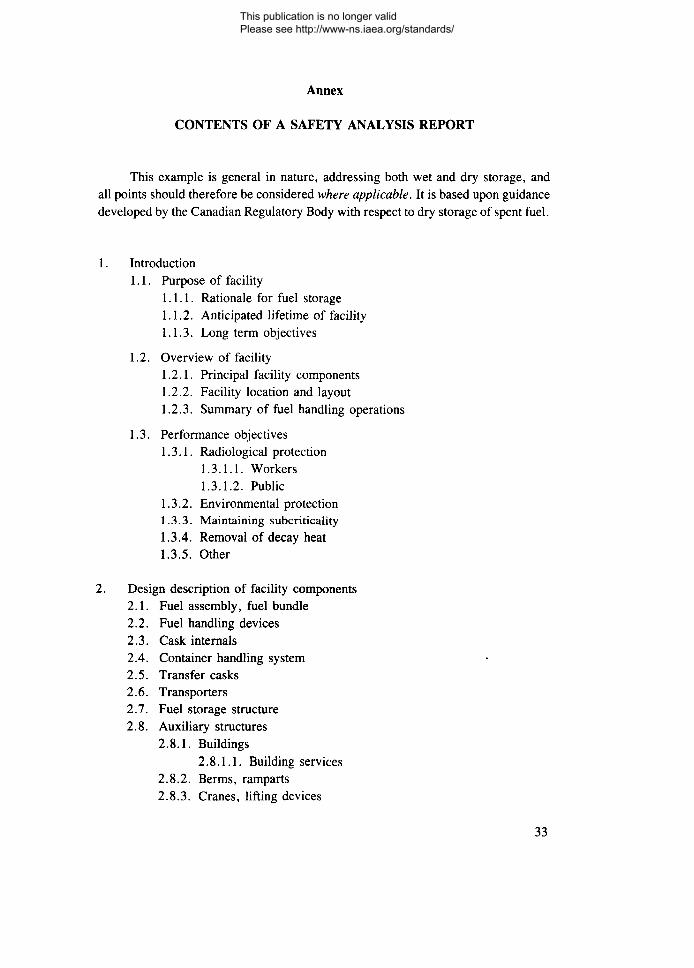
Annex
CONTENTS OF A SAFETY ANALYSIS REPORT
This example is general in nature, addressing both wet and dry storage, andall points should therefore be considered where applicable. It is based upon guidancedeveloped by the Canadian Regulatory Body with respect to dry storage of spent fuel.
1. Introduction1.1. Purpose of facility
1.1.1. Rationale for fuel storage1.1.2. Anticipated lifetime of facility1.1.3. Long term objectives
1.2. Overview of facility1.2.1. Principal facility components1.2.2. Facility location and layout1.2.3. Summary of fuel handling operations
1.3. Performance objectives1.3.1. Radiological protection
1.3.1.1. Workers1.3.1.2. Public
1.3.2. Environmental protection1.3.3. Maintaining subcriticality1.3.4. Removal of decay heat1.3.5. Other
2. Design description of facility components2.1. Fuel assembly, fuel bundle2.2. Fuel handling devices2.3. Cask internals2.4. Container handling system2.5. Transfer casks2.6. Transporters2.7. Fuel storage structure2.8. Auxiliary structures
2.8.1. Buildings2.8.1.1. Building services
2.8.2. Berms, ramparts2.8.3. Cranes, lifting devices
33
This publication is no longer valid Please see http://www-ns.iaea.org/standards/
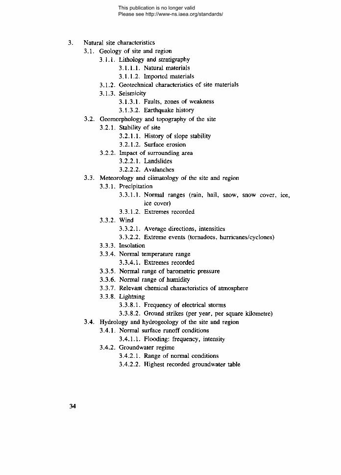
3. Natural site characteristics3.1. Geology of site and region
3.1.1. Lithology and stratigraphy3.1.1.1. Natural materials3.1.1.2. Imported materials
3.1.2. Geotechnical characteristics of site materials3.1.3. Seismicity
3.1.3.1. Faults, zones of weakness3.1.3.2. Earthquake history
3.2. Geomorphology and topography of the site3.2.1. Stability of site
3.2.1.1. History of slope stability3.2.1.2. Surface erosion
3.2.2. Impact of surrounding area3.2.2.1. Landslides3.2.2.2. Avalanches
3.3. Meteorology and climatology of the site and region3.3.1. Precipitation
3.3.1.1. Normal ranges (rain, hail, snow, snow cover, ice,ice cover)
3.3.1.2. Extremes recorded3.3.2. Wind
3.3.2.1. Average directions, intensities3.3.2.2. Extreme events (tornadoes, hurricanes/cyclones)
3.3.3. Insolation3.3.4. Normal temperature range
3.3.4.1. Extremes recorded3.3.5. Normal range of barometric pressure3.3.6. Normal range of humidity3.3.7. Relevant chemical characteristics of atmosphere3.3.8. Lightning
3.3.8.1. Frequency of electrical storms3.3.8.2. Ground strikes (per year, per square kilometre)
3.4. Hydrology and hydrogeology of the site and region3.4.1. Normal surface runoff conditions
3.4.1.1. Flooding: frequency, intensity3.4.2. Groundwater regime
3.4.2.1. Range of normal conditions3.4.2.2. Highest recorded groundwater table
34
This publication is no longer valid Please see http://www-ns.iaea.org/standards/

3.4.3. Coastal processes3.4.3.1. Wave action3.4.3.2. Tides3.4.3.3. Storm surges3.4.3.4. Shore erosion
3.5. Potential for natural fires or explosions3.5.1. Volcanoes, forest fires, oil seeps, gas venting, etc.
3.6. Terrestrial fauna and flora of the site3.7. Aquatic fauna and flora adjacent to the site
4. Human environment surrounding the site4.1. Population distribution4.2. Agriculture4.3. Residential and commercial neighbourhoods
4.3.1. Mix and nature of commercial pursuits4.4. Industrial parks
4.4.1. Mix and nature of industry4.5. Transportation routes adjacent to the site
4.5.1. Waterways4.5.2. Roads4.5.3. Railway lines4.5.4. Air corridors
4.6. Mining and excavation4.7. Nuclear installations4.8. Electrical power stations (including nuclear)4.9. Potentially hazardous engineering works such as upstream dams
5. Design basis5.1. Fuel characteristics
5.1.1. Physical description of fuel assembly, fuel bundle5.1.1.1. Surface deposits on fuel assembly, fuel bundle
5.1.2. Initial enrichment5.1.3. Burnup, power history5.1.4. Minimum cooling period5.1.5. Isotopic composition at time of storage5.1.6. Radiation fields at time of storage5.1.7. Reactivity at time of storage5.1.8. Decay heat production at time of storage
5.2. Fuel load5.2.1. Fuel load per storage unit5.2.2. Total fuel load in facility
5.3. Intended fuel storage time
35
This publication is no longer valid Please see http://www-ns.iaea.org/standards/
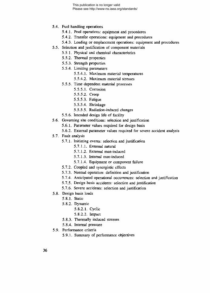
5.4. Fuel handling operations5.4.1. Pool operations: equipment and procedures5.4.2. Transfer operations: equipment and procedures5.4.3. Loading or emplacement operations: equipment and procedures
5.5. Selection and justification of component materials5.5.1. Physical and chemical characteristics5.5.2. Thermal properties5.5.3. Strength properties5.5.4. Limiting parameters
5.5.4.1. Maximum material temperatures5.5.4.2. Maximum material stresses
5.5.5. Time dependent material processes5.5.5.1. Corrosion5.5.5.2. Creep5.5.5.3. Fatigue5.5.5.4. Shrinkage5.5.5.5. Radiation-induced changes
5.5.6. Intended design life of facility5.6. Governing site conditions: selection and justification
5.6.1. Parameter values required for design basis5.6.2. External parameter values required for severe accident analysis
5.7. Fault analysis5.7.1. Initiating events: selection and justification
5.7.1.1. External natural5!7.1.2. External man-induced5.7.1.3. Internal man-induced5.7.1.4. Equipment or component failure
5.7.2. Coupled and synergistic effects5.7.3. Normal operation: definition and justification5.7.4. Anticipated operational occurrences: selection and justification5.7.5. Design basis accidents: selection and justification5.7.6. Severe accidents: selection and justification
5.8. Design basis loads5.8.1. Static5.8.2. Dynamic
5.8.2.1. Cyclic5.8.2.2. Impact
5.8.3. Thermally induced stresses5.8.4. Internal pressure
5.9. Performance criteria5.9.1. Summary of performance objectives
36
This publication is no longer valid Please see http://www-ns.iaea.org/standards/

5.9.2. Criteria values5.9.2.1. Radiation fields5.9.2.2. Contamination levels5.9.2.3. Zones for contamination and radiation control5.9.2.4. Releases (radiological, non-radiological)5.9.2.5. Maximum fuel cladding temperature5.9.2.6. Other
5.9.3. Justification of surrogate estimates5.9.4. Justification of criteria values
6. Design justification6.1. States of the facility considered
6.1.1. Normal operation (Reference: Sections 5.7.3 and 5.8)6.1.2. Anticipated operational occurrences (Reference: Sections 5.7.4
and 5.8)6.1.3. Design basis accidents (Reference: Sections 5.7.5 and 5.8)6.1.4. Severe accidents (Reference: Sections 5.7.6 and 5.8)
6.2. Summary of analyses6.2.1. Foundation analysis6.2.2. Structural integrity of facility components (Reference: Section 2)
6.2.2.1. Pool wall6.2.2.2. Pool floor
6.2.3. Heat transfer6.2.4. Dose estimates and ALARA demonstration
6.2.4.1. Worker dose estimates for maximum individual, groupaverage and collective dose
6.2.4.2. Public dose estimates for critical group and collective6.2.5. Factors of safety
6.3. Analytical conclusions6.3.1. Shielding6.3.2. Containment6.3.3. Fuel geometry6.3.4. Change of moderation6.3.5. Dissipation of decay heat
6.4. Accident response6.4.1. Available resources
6.4.1.1. Equipment, material6.4.1.2. Personnel
6.4.2. Contingency plans6.4.3. Administrative structure for management of response6.4.4. Mitigating effects as a result of response
37
This publication is no longer valid Please see http://www-ns.iaea.org/standards/
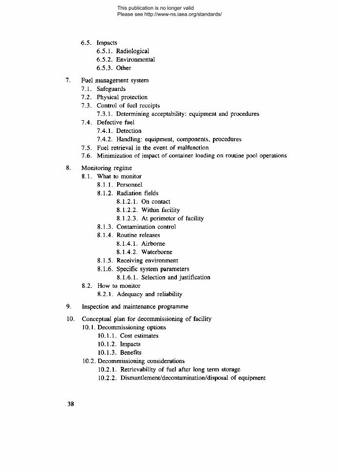
6.5. Impacts6.5.1. Radiological6.5.2. Environmental6.5.3. Other
7. Fuel management system7.1. Safeguards7.2. Physical protection7.3. Control of fuel receipts
7.3.1. Determining acceptability: equipment and procedures7.4. Defective fuel
7.4.1. Detection7.4.2. Handling: equipment, components, procedures
7.5. Fuel retrieval in the event of malfunction7.6. Minimization of impact of container loading on routine pool operations
8. Monitoring regime8.1. What to monitor
8.1.1. Personnel8.1.2. Radiation fields
8.1.2.1. On contact8.1.2.2. Within facility8.1.2.3. At perimeter of facility
8.1.3. Contamination control8.1.4. Routine releases
8.1.4.1. Airborne8.1.4.2. Waterborne
8.1.5. Receiving environment8.1.6. Specific system parameters
8.1.6.1. Selection and justification8.2. How to monitor
8.2.1. Adequacy and reliability
9. Inspection and maintenance programme
10. Conceptual plan for decommissioning of facility10.1. Decommissioning options
10.1.1. Cost estimates10.1.2. Impacts10.1.3. Benefits
10.2. Decommissioning considerations10.2.1. Retrievability of fuel after long term storage10.2.2. Dismantlement/decontamination/disposal of equipment
38
This publication is no longer valid Please see http://www-ns.iaea.org/standards/
10.2.3. Dismantlement/decontamination/disposal of storage containersand structures
10.2.4. Restoration of site10.3. Programme to review and update decommissioning plan periodically
11. Quality assurance programme11.1. Design and analysis11.2. Construction of facility
11.2.1. Fabrication of components11.3. Operation
11.3.1. Fuel handling11.3.2. Fuel management system11.3.3. Monitoring11.3.4. Inspection and maintenance
11.4. Decommissioning
39
This publication is no longer valid Please see http://www-ns.iaea.org/standards/

This publication is no longer valid Please see http://www-ns.iaea.org/standards/

DEFINITIONS
The definitions below are those specific to this document. Other terms in thisdocument have the meaning as defined in other publications of the IAEA.
The specific definitions of plant states given below are taken from NUSS documents.
The relationships among the following fundamental definitions of plant statesare illustrated by the accompanying diagram.
Plant states
Operational states
AnticipatedNormal operational
operation I occurrences
Accidents
Accidentconditions
Severeaccidents
Designbasis
accidents
Accident management
Operational States
States defined under normal operation or anticipated operational occurrences.
Normal Operation
Operation of a spent fuel storage facility within specified operational limits andconditions including fuel handling, storage, retrieval and fuel monitoring, main-tenance and testing.
41
This publication is no longer valid Please see http://www-ns.iaea.org/standards/
Anticipated Operational Occurrences1
All operational processes deviating from normal operation which are expectedto occur once or several times during the operating life of the fuel storage facilityand which, in view of appropriate design provisions, do not cause any significantdamage to items important to safety nor lead to accident conditions.
Accident (or Accident State)
A state defined under accident conditions or severe accidents.
Accident Conditions
Deviations2 from operational states in which the releases of radioactivematerials are kept to acceptable limits by appropriate design features. These devia-tions do not include severe accidents.
Design Basis Accidents
Accident conditions against which the spent fuel storage facility is designedaccording to established design criteria.
Severe Accidents
Spent fuel storage facility states beyond accident conditions, including thosecausing significant fuel degradation.
Accident Management
Accident management is the taking of a set of actions
— during the evolution of an event sequence, before the design basis of the plantis exceeded, or
— during severe accidents without allowing unacceptable radionuclide releases tothe environment
to return the facility to a controlled safe state and to mitigate any consequences ofthe accident.
1 Examples of anticipated operational occurrences are loss of normal electric power,malfunction of individual items of a normally running plant and failure to function ofindividual items of control equipment.
2 A deviation may be, for example, a major fuel failure caused by equipment mal-function, operator error, etc.
42
This publication is no longer valid Please see http://www-ns.iaea.org/standards/

Other definitions used throughout this document are as follows:
Acceptable Limits
Limits acceptable to the Regulatory Body.
Applicant
The organization that applies for formal granting of a licence to performspecific activities related to siting, design, construction, commissioning, operationand decommissioning of a spent fuel storage facility.
Barrier
A natural or engineered feature which delays or prevents material migrationto or from storage components. Facilities may include multiple barriers.
Burnup Credit
The assumption in criticality safety analysis that considers the reduction inreactivity due to changes of fissile material, and/or increase in fission productneutron absorbers in spent fuel that has occurred as a result of use in a nuclearreactor.
Concrete Canister (or Silo)
A concrete canister is a massive container comprising one or more individualstorage cavities. It is usually circular in cross-section, with its long axis vertical.Containment and shielding are provided by an inner, sealed liner and the massiveconcrete of the canister body. Heat removal is accomplished by radiant transfer, con-duction and convection within the body of the canister and natural convection at itsexterior surface. Canisters may be located in enclosed or non-enclosed areas.
Containment System for Spent Fuel Storage
Systems, including ventilation, that act as barriers between areas containingradioactive substances and the environment.
Dry Storage
In dry storage, spent fuel is surrounded by a gas environment such as air oran inert gas. Dry storage facilities include the storage of spent fuel in casks, silosor vaults.
43
This publication is no longer valid Please see http://www-ns.iaea.org/standards/
Fault
A failure of a single device or component to perform its safety function whenrequired to do so by a demand on the safety system.
Fuel Assembly
A grouping of fuel elements which is not taken apart during the handling,storage, retrieval and monitoring activities of the spent fuel storage facility. It mayinclude non-fuel components such as control rod spiders, burnable absorber rodassemblies, control rod elements, thimble plugs, fission chambers, neutron sourcesand fuel channels that are contained in, or are an integral part of, the fuel assemblybut do not require special handling.
Fuel Element
The smallest structurally discrete part of a fuel assembly that has fuel as itsprincipal constituent.
HAZOP method
HAZOP is a hazard and operability study. It is a systematic, structured, criticalexamination of a proposed design or operation, seeking to identify safety or opera-tional questions requiring further study. It is carried out by an appropriate multi-disciplinary team, studying possible deviations from the design or process intent asthe means of identification of such questions or issues.
Licence
Authorization issued to the applicant by the Regulatory Body to perform speci-fied activities related to siting, design, construction, commissioning, operation anddecommissioning of the spent fuel storage facility.
Licensee
The holder of a licence.
Operating Organization
The organization authorized pursuant to a licence issued by the RegulatoryBody to operate the spent fuel storage facility.
44
This publication is no longer valid Please see http://www-ns.iaea.org/standards/
Operation
All activities performed to achieve the purpose for which the spent fuel storagefacility was constructed, including maintenance, inspection and other associatedactivities related to spent fuel handling, storage, retrieval and monitoring.
Operational Limits and Conditions
A set of rules which set forth parameter limits, the functional capability andthe performance levels of equipment and personnel approved by the Regulatory Bodyfor safe operation of the spent fuel storage facility.
Postulated Initiating Events
Identified events that lead to anticipated operational occurrences or accidentconditions and their consequential failure effects.3
Regulatory Body
A national authority or a system of authorities designated by a Member State,assisted by technical and other advisory bodies, and having the legal authority forconducting the licensing process, for issuing licences and thereby for regulating thespent fuel storage facility. The Regulatory Body will consider the siting, design, con-struction, commissioning, operation and decommissioning or specified aspectsthereof.4
Residual Heat
The heat originating from radioactive decay in the spent nuclear fuel.
Silo (see Concrete Canister)
Site
The area containing the spent fuel storage facility, defined by a boundary andunder effective control of the plant management.
3 The primary causes of postulated initiating events may be credible equipmentfailures and operator errors (both within and external to the spent fuel storage facility), or maninduced or natural events. The specification of the postulated initiating events is to be accept-able to the Regulatory Body for the spent fuel storage facility.
4 This national authority could be either the government itself, or one or more depart-ments of the government, or a body or bodies specially vested with appropriate legal authority.
45
This publication is no longer valid Please see http://www-ns.iaea.org/standards/
Site Personnel
All persons working on the site, either permanently or temporarily.
Spent Fuel Storage Facility
An installation used for the interim storage of fuel assemblies and relatedcomponents after their removal from the reactor pool and before reprocessing ordisposal as radioactive waste.
Storage Cask, Cask
A storage cask is a massive container which may or may not be transportable.It provides shielding and containment of spent fuel by physical barriers which mayinclude the metal or concrete body of the cask and welded or sealed liners, canistersor lids. Heat is removed from the stored fuel by radiant transfer to the surroundingenvironment and natural or forced convection. Casks may be located in enclosed ornon-enclosed areas.
Vaults
Vaults consist of above- or below-ground reinforced concrete buildings con-taining arrays of storage cavities suitable for containment of one or more fuel units.Shielding is provided by the exterior structure. Heat removal is normally accom-plished by circulating air or gas over the exterior of the fuel containing units orstorage cavities, and subsequently exhausting this air directly to the outsideatmosphere or dissipating the heat via a secondary heat removal system.
Wet Storage
Wet storage facilities for spent fuel are those facilities which store spent fuelin water. The universal mode of wet storage consists of storing spent fuel assembliesor elements in water pools, usually supported on racks or in baskets, and/or incanisters which also contain water. The pool water surrounding the fuel provides forheat dissipation and radiation shielding, and the racks or other devices ensure ageometrical configuration which maintains subcriticality.
46
This publication is no longer valid Please see http://www-ns.iaea.org/standards/
REFERENCES
[1] INTERNATIONAL ATOMIC ENERGY AGENCY, Design of Spent Fuel StorageFacilities, Safety Series No. 116, IAEA, Vienna (1994).
[2] INTERNATIONAL ATOMIC ENERGY AGENCY, Operation of Spent Fuel StorageFacilities, Safety Series No. 117, IAEA, Vienna (1994).
[3] INTERNATIONAL ATOMIC ENERGY AGENCY, Fuel Handling and StorageSystems in Nuclear Power Plants: A Safety Guide, Safety Series No. 50-SG-D10,IAEA, Vienna (1984).
[4] INTERNATIONAL ATOMIC ENERGY AGENCY, Regulations for the Safe Trans-port of Radioactive Material, 1985 Edition (As Amended 1990), Safety Series No. 6,IAEA, Vienna (1990).
[5] INTERNATIONAL ATOMIC ENERGY AGENCY, Interfaces between Transport andGeological Disposal Systems for High Level Waste and Spent Nuclear Fuel, IAEA-TECDOC-764, IAEA, Vienna (1994).
[6] INTERNATIONAL ATOMIC ENERGY AGENCY, International Basic Safety Stan-dards for Protection Against Ionizing Radiation and for the Safety of Radiation Sources— Interim Edition, Safety Series No. 115, IAEA, Vienna (1995).
[7] INTERNATIONAL ATOMIC ENERGY AGENCY, The Safety of Nuclear Installa-tions, Safety Series No. 110, IAEA, Vienna (1993).
[8] INTERNATIONAL ATOMIC ENERGY AGENCY, Basic Safety Principles forNuclear Power Plants — A Report by the International Safety Advisory Group, SafetySeries No. 75-INSAG-3, IAEA, Vienna (1988).
[9] INTERNATIONAL ATOMIC ENERGY AGENCY, External Man-Induced Events inRelation to Nuclear Power Plant Design: A Safety Guide, Safety Series No. 50-SG-D5,IAEA, Vienna (1982).
[10] NUCLEAR REGULATORY COMMISSION, Licensing Requirements for theIndependent Storage of Spent Nuclear Fuel and High-Level Radioactive Waste, Rulesand Regulations 10 CFR 72, US Govt Printing Office, Washington, DC (1994).
BIBLIOGRAPHY
GENERAL
AMERICAN NUCLEAR SOCIETY, Design Criteria for an Independent Spent Fuel StorageInstallation (Water Pool Type), Rep. ANSI/ANS-57.7-1988, ANS, La Grange Park, IL(1989).
AMERICAN NUCLEAR SOCIETY, Design Criteria for an Independent Spent Fuel StorageInstallation (Dry Storage Type), Rep. ANSI/ANS-57.9-1992, ANS, La Grange Park, IL(1992).
47
This publication is no longer valid Please see http://www-ns.iaea.org/standards/
NUCLEAR REGULATORY COMMISSION, Standard Format and Content for the SafetyAnalysis Report for an Independent Spent Fuel Storage Installation (Water-Basin Type),Regulatory Guide 3.44 (Rev. 2), USNRC, Washington, DC (Jan. 1989).
NUCLEAR REGULATORY COMMISSION, Standard Format and Content for the SafetyAnalysis Report for an Independent Spent Fuel Storage Installation or Monitored RetrievableStorage Installation (Dry Storage), Regulatory Guide 3.48 (Rev. 1), USNRC, Washington,DC (Aug. 1989).
NUCLEAR REGULATORY COMMISSION, Design of an Independent Spent Fuel StorageInstallation (Water-Basin Type), Regulatory Guide 3.49, USNRC, Washington, DC (Dec.1981).
NUCLEAR REGULATORY COMMISSION, Standard Format and Content for a LicenceApplication to Store Spent Fuel and High-level Radioactive Waste, Regulatory Guide 3.50(Rev. 1), USNRC, Washington, DC (Sep. 1989).
NUCLEAR REGULATORY COMMISSION, Applicability of Existing Regulatory Guides tothe Design and Operation of an Independent Spent Fuel Storage Installation, Regulatory Guide3.53, USNRC, Washington, DC (July 1989).
NUCLEAR REGULATORY COMMISSION, Spent Fuel Heat Generation in an IndependentSpent Fuel Storage Installation, Regulatory Guide 3.54, USNRC, Washington, DC (Sep.1984).
NUCLEAR REGULATORY COMMISSION, Design of an Independent Spent Fuel StorageInstallation (Dry Storage), Regulatory Guide 3.60, USNRC, Washington, DC (Mar. 1987).
NUCLEAR REGULATORY COMMISSION, Standard Format and Content for a TopicalSafety Analysis Report for a Spent Fuel Dry Storage Cask, Regulatory Guide 3.61, USNRC,Washington, DC (Feb. 1989).
NUCLEAR REGULATORY COMMISSION, Standard Format and Content for the SafetyAnalysis Report for On-site Storage of Spent Fuel Casks, Regulatory Guide 3.62, USNRC,Washington, DC (Feb. 1989).
STEWART, C.W., et al., Cobra-IV: The Model and the Method, Rep. BNWL-2214, PacificNorthwest Laboratory, Richland, WA (1977).
HEALTH AND SAFETY EXECUTIVE, Safety Assessment Principles for Nuclear PowerPlants, Sheffield, UK (1992).
SAEGUSA, T., et al., "Verification tests on cask-storage method for storing spent fuel atreactor", PATRAM '92: Packaging and Transportation of Radioactive Materials (Proc. 10thInt. Symp. Yokohama, 1991), and the articles referenced. Available from INIS.
48
This publication is no longer valid Please see http://www-ns.iaea.org/standards/
ISOTOPIC COMPOSITION/DECAY HEAT
Examples of relevant methodologies are given in the following references:
BELL, M.J., ORIGEN — The ORNL Isotope Generation and Depletion Code,Rep. ORNL-4628, Oak Ridge National Laboratory, Oak Ridge, TN (1973).
BRISSENDEN, R.J., BENDALL, D.E., "The physics of MONK 6: An overview", Newsl.No. 29, NBA Data Bank, Atomic Energy Research Establishment, Winfrith, UK (May 1983)107-168.
CLEGG, L.J., COADY, J.R., Radioactive Decay Properties of CANDU Fuel, Volume 1:The Natural Uranium Fuel Cycle, Rep. AECL-4436/1, Atomic Energy of Canada Ltd (1977).
CROFF, A.G., A User's Manual for the ORIGEN2 Computer Code, Rep. ORNL/TM-7175,Oak Ridge National Laboratory, Oak Ridge, TN (1980).
CROFF, A.G., ORIGEN2 — A Revised and Updated Version of the Oak Ridge IsotopeGeneration and Depletion Code, Rep. ORNL-5621, Oak Ridge National Laboratory, OakRidge, TN (1980).
CROFF, A.G., ORIGEN2 — Isotope Generation and Depletion Code — Matrix ExponentialMethod, Rep. ORNL-CCC-371, Oak Ridge National Laboratory, Oak Ridge, TN (1982).
HEEB, C.M., "Comparison of spent fuel decay heat rate: ORIGEN2 predictions andcalorimeter measurements", Spent Fuel Storage Technology (Proc. 3rd Int. Symp./WorkshopSeattle, WA, 1986), Pacific Northwest Lab., Richland, WA (1986).
HENDRICKS, J.S., WHALEN, D.J., CARDON, D.A., UHLE, J.L., MCNP NeutronBenchmarks, Rep. LA-UR-91-3723, CONF-920606-1, Los Alamos National Laboratory,Los Alamos, NM (1991).
HERMANN, O.W., WESTFALL, R.M., ORIGEN-S: SCALE System Module to CalculateFuel Depletion, Actinide Transmutation, Fission Product Buildup and Decay, and AssociatedRadiation Source Terms, Section F7, Rep. NUREG/CR-0200 (Rev. 2), Vol. 2, Oak RidgeNational Laboratory, Oak Ridge, TN (1984).
HERMANN, O.W., PARKS, C.V., RYMAN, J.C., "Spent fuel decay heat calculationsusing ORIGEN-S", Spent Fuel Storage Technology (Proc. 3rd Int. Symp./Workshop Seattle,WA, 1986), Pacific Northwest Lab., Richland, WA (1986).
SHERRIFFS, V.S.W., MONK — A General Purpose Monte Carlo Neutronics Program,Rep. SRD-R-86, UKAEA Safety and Reliability Directorate, Culcheth (Jan. 1978).
SMITH, H.J., TAIT, J.C., VON MASSOW, R.E., Radioactive Decay Properties of BruceA CANDU UO2 Fuel and Fuel Recycle Waste, Rep. AECL-9072, Atomic Energy of CanadaLtd (1987).
TAIT, J.C., GAULD, I.C., WILKIN, G.B., Derivation of Initial Radionuclide Inventoriesfor the Safety Assessment of the Disposal of Used CANDU Fuel, Rep. AECL-9881, AtomicEnergy of Canada Ltd (1989).
49
This publication is no longer valid Please see http://www-ns.iaea.org/standards/
WALKER, W.H., HEBERT, A., FISSPROD-3: An Expanded Fission Product AccumulationProgram Using ENDF/B-V Decay Data, Rep. AECL-6993, Atomic Energy of Canada Ltd(1982).
CRITICALITY
ASKEW, J., "The WIMS family of codes", Newsl. No. 26, NBA Data Bank, Atomic EnergyResearch Establishment, Winfrith, UK (April 1981) 7-44.
ASKEW, J., HALSALL, M., "Twenty-five years of experience with the WIMS assemblycodes", Advances in Reactor Physics, Mathematics and Computation, Vol. 3, Socie'te'
francaise d'energie nucleaire (SFEN), Paris (1987).
DONNELLY J.V., WIMS-CRNL: A Users' Manual for the Chalk River Version of WIMS,Rep. AECL-8955, Atomic Energy of Canada Ltd (1986).
EDENIUS, M., AHLIN, A., "Casmo-3: new features, benchmarking, and advanced applica-tions", Advances in Reactor Physics, Mathematics and Computation, Vol. 3, Socie'te'francaise d'energie nucle'aire (SFEN), Paris (1987).
EDENIUS, M., SMITH, K.S., VERPLANCK, D.M., AHLIN, A., JERNBERG, P., "Newdata and methods for CASMO and SIMULATE", Reactor Physics and Safety (Proc. TopicalMtg 1986), Vol. 2, American Nuclear Society, La Grange Park, IL (1986) 1115-1126.
OAK RIDGE NATIONAL LABORATORY, SCALE: A Modular Code System for Perform-ing Standardized Computer Analyses for Licensing Evaluation, Rep. NUREG/CR-0200 orRep. ORNL/NUREG/CSD-2, Vols 1, 2 and 3, ORNL, Oak Ridge, TN (1982, revised 1983and 1984).
PETRIE, L.M., CROSS, N.F., KENO-IV: An Improved Monte Carlo Criticality Program,Rep. ORNL-4938, Oak Ridge National Laboratory, Oak Ridge, TN (1975).
UNITED KINGDOM ATOMIC ENERGY AUTHORITY, MONK 5.2 - A General PurposeMonte Carlo Neutronics Code System, Publications SRD-R-86 and SRD-R-88, UKAEA,Health and Safety Branch, Harwell (1986).
HEAT TRANSFER
A widely used technique for analysing the heat transfer characteristics of a dry
storage container (e.g. a cask or canister) is to represent the contents as a porous
medium. A proper representation requires empirical information derived from
geometries which are similar to that of the fuel and its container. This information
may be available in the open scientific and engineering literature or, if unavailable,
must be obtained by the operating organization through appropriate experimentation.
50
This publication is no longer valid Please see http://www-ns.iaea.org/standards/

When a representative porous medium has been defined, the analysis proceedsusing conventional thermohydraulics techniques based upon finite element or finitedifference methods.
Example analyses may be found in:
OAK RIDGE NATIONAL LABORATORY, SCALE: A Modular Code System for Perform-ing Standardized Computer Analyses for Licensing Evaluation, Rep. NUREG/CR-0200 orRep. ORNL/NUREG/CSD-2, Vols 1, 2 and 3, ORNL, Oak Ridge, TN (1982, revised 1983and 1984).
RECTOR, D.R., CUTA, J.M., LOMBARDO, N.J., MICHENER, T.E., WHEELER, C.L.,OBRA-SFS: A Thermal-Hydraulic Analysis Code, Rep. PNL-6049, Pacific Northwest Lab.,Richland, WA (1986).
SCHWARTZ, M.W., WITTE, M.C., Spent Fuel Cladding Integrity During Dry Storage,Rep. UCID-21181, Lawrence Livermore Laboratory, Berkeley, CA (Sep. 1987).
TARALIS, D., Thermal Analysis of an Irradiated Fuel Road Cask, Part I, Rep. 85-240-K,Ontario Hydro Research Division, Toronto (1986).
TARALIS, D., et al., Thermal Testing of a Half-Scale Concrete Integrated Container Cavity,Rep. 89-241-K, Ontario Hydro Research Division, Toronto (1989).
SHIELDING
GROVE ENGINEERING, INC., Micro Shield: A Photon/Gamma Ray Shielding and DoseAssessment Program, Grove Engineering, Inc., 15215 Shady Grove Rd., Suite 200,Rockville, MD 20850 (revised 1994).
MALENFANT, R.E., QAD — Point Kernel General Purpose Shielding Codes, Rep.ORNL-4181, Oak Ridge National Laboratory, Oak Ridge, TN (1970).
STRAKER, E.A., et al., The MORSE Code — A Multigroup Neutron and Gamma RayMonte Carlo Transport Code, Rep. ORNL-4585, Oak Ridge National Laboratory, Oak Ridge,TN (1970).
DISPERSION
CANADIAN STANDARDS ASSOCIATION, Guidelines for Calculating Radiation Doses tothe Public from a Release of Airborne Radioactive Material under Hypothetical Accident Con-ditions in Nuclear Reactors, CAN/CSA-N288.2-M91, National Standard of Canada, CSA,Rexdale, Ontario (1991).
51
This publication is no longer valid Please see http://www-ns.iaea.org/standards/

PATHWAYS ANALYSIS
CANADIAN STANDARDS ASSOCIATION, Guidelines for Calculating Derived ReleaseLimits for Radioactive Material in Airborne and Liquid Effluents for Normal Operation ofNuclear Facilities, CAN/CSA-N288.1 — M87, National Standard of Canada, CSA, Rexdale,Ontario (1987).
52
This publication is no longer valid Please see http://www-ns.iaea.org/standards/

CONTRIBUTORS TO DRAFTING AND REVIEW
Andreescu, N. Institute of Power Studies and Design Nuclear Objectives, Romania
Baekelandt, L. National Agency for Radioactive Waste and Fissile Materials'ONDRAF', Belgium
Baillif, L. NUSYS, France
Bartak, L. State Office for Nuclear Safety, Czech Republic
Brzobohaty, K. Czech Power Company, Czech Republic
Buchheim, B. Nordostschweizerische Kraftwerke, Switzerland
Buday, G. Paks Nuclear Power Plant, Hungary
Capp, P.O. AEA Technology, United Kingdom
Chaudon, L. Centre d'etudes de la Valle'e du Rhone, Site de Marcoule, France
Conlon, P. Atomic Energy Control Board, Canada
Fajman, V. State Office for Nuclear Safety, Czech Republic
Goldschmidt, A. Comision Nacional de Energia Atomica, Argentina
Gomit, M. IPSN/DES-CEN/FAR, France
Gonen, Y. Israel Atomic Energy Commission, Israel
Gurevitz, Y. Israel Atomic Energy Commission, Israel
Hashimi, J.A. Permanent Mission of Pakistan, Austria
Heimlich, F. Bundesamt fur Strahlenschutz, Germany
Holton, W.C. Private consultant, United States of America
Hrazdil, O. Nuclear Research Institute, Czech Republic
Ikushima, T. Nuclear Power Engineering Center, Japan
Jack, G.C. Atomic Energy Control Board, Canada
Jameel, M. Permanent Mission of Pakistan, Austria
Janberg, K. Gesellschaft fur Nuklear-Service mbH, Germany
Kadarmetov, I. All-Union Scientific Research Institute of Inorganic Materials,Russian Federation
Koshkin, I.S. MAPI, Russian Federation
Li, G. Beijing Institute of Nuclear Engineering, China
Makartsuk, T. VNIPIEhT, Russian Federation
53
This publication is no longer valid Please see http://www-ns.iaea.org/standards/
Malstrom, H. Brennelement-Zwischenlager Ahaus GmbH, Germany
Mason, D. Health and Safety Executive, Nuclear Installations Inspectorate,United Kingdom
Muller, J. Zavod Atomprojekt, Czech Republic
Niel, J.C. MICE/DSIN, France
Peehs, M. Siemens AG, KWU/BP, Germany
Pinkas, V. Czech Atomic Energy Commission, Czech Republic
Porteau, C. Centre d'etudes de la Vallee du Rhone, Site de Marcoule, France
Prasad, A.N. Bhabha Atomic Research Centre, India
Quick, M. Nuclear Electric pic, United Kingdom
Rasmussen, R. Duke Power Co., United States of America
Resta, E. ENEA/DISP, Italy
Richardson, J. Roy F. Weston Co., United States of America
Risoluti, P. ENEA, Italy
Saegusa, T. Central Research Institute of the Electric Power Industry, Japan
Schwartz, M. Private consultant, United States of America
Sheppard, G.T. British Nuclear Fuels pic, United Kingdom
Soucek, B. Czech Power Board, Czech Republic
Sturz, F. Office of Nuclear Material Safety and Safeguards,Nuclear Regulatory Commission, United States of America
Takala, H. Finnish Centre for Radiation and Nuclear Safety, Finland
Takats, F. International Atomic Energy Agency
Taylor, R.E. Health and Safety Executive, Nuclear Installations Inspectorate,United Kingdom
Tikhonov, N. VNIPIEhT, Russian Federation
Turner, M. Slovak Power Enterprise, Slovak Republic
Valach, M. Nuclear Research Institute, Czech Republic
Wertelaers, A. Ministere de I'emploi et du travail, Belgium
54
This publication is no longer valid Please see http://www-ns.iaea.org/standards/
Consultants Meetings
Vienna, Austria: 18-21 June 1991Vienna, Austria: 16-20 March 1992
Vienna, Austria: 29 March-2 April 1993Vienna, Austria: 6-8 April 1994
Advisory Group Meeting
Vienna, Austria: 25-29 November 1991
Technical Committee Meetings
Vienna, Austria: 2-5 November 1992Vienna, Austria: 13-15 September 1993
55
This publication is no longer valid Please see http://www-ns.iaea.org/standards/

This publication is no longer valid Please see http://www-ns.iaea.org/standards/

LIST OF NUSS PROGRAMME TITLES
It should be noted that some books in theseries may be revised in the near future.
Those that have already been revised are indicated by theaddition of '(Rev. 1)' to the number.
1. GOVERNMENTAL ORGANIZATION
50-C-G (Rev. 1)
50-SG-G1
50-SG-G2
50-SG-G3
50-SG-G4
50-SG-G6
50-SG-G8
50-SG-G9
Code on the safety of nuclear power plants: Governmental 1988organization
Safety Guides
Qualifications and training of staff of the regulatory body 1979for nuclear power plants
Information to be submitted in support of licensing 1979applications for nuclear power plants
Conduct of regulatory review and assessment during the 1980licensing process for nuclear power plants
Inspection and enforcement by the regulatory body for 1980nuclear power plants
Preparedness of public authorities for emergencies at 1982nuclear power plants
Licences for nuclear power plants: Content, format and 1982legal considerations
Regulations and guides for nuclear power plants 1984
2. SITING
50-C-S (Rev. 1)
50-SG-S1 (Rev. 1)
50-SG-S3
50-SG-S4
Code on the safety of nuclear power plants: Siting 1988
Safety Guides
Earthquakes and associated topics in relation to nuclear 1991power plant siting
Atmospheric dispersion in nuclear power plant siting 1980
Site selection and evaluation for nuclear power plants 1980with respect to population distribution
57
This publication is no longer valid Please see http://www-ns.iaea.org/standards/
50-SG-S5 External man-induced events in relation to nuclear power 1981plant siting
50-SG-S6 Hydrological dispersion of radioactive material in relation 1985to nuclear power plant siting
50-SG-S7 Nuclear power plant siting: Hydrogeological aspects 1984
50-SG-S8 Safety aspects of the foundations of nuclear power plants 1986
50-SG-S9 Site survey for nuclear power plants 1984
50-SG-S10A Design basis flood for nuclear power plants on river sites 1983
50-SG-S10B Design basis flood for nuclear power plants on coastal 1983sites
50-SG-S11A Extreme meteorological events in nuclear power plant 1981siting, excluding tropical cyclones
50-SG-S11B Design basis tropical cyclone for nuclear power plants 1984
3. DESIGN
50-C-D (Rev. 1)
50-SG-D1
50-SG-D2 (Rev. 1)
50-SG-D3
50-SG-D4
50-SG-D5
50-SG-D6
50-SG-D7 (Rev. 1)
50-SG-D8
50-SG-D9
Code on the safety of nuclear power plants: Design 1988
Safety Guides
Safety functions and component classification for 1979BWR, PWR and PTR
Fire protection in nuclear power plants 1992
Protection system and related features in nuclear 1980power plants
Protection against internally generated missiles and 1980their secondary effects in nuclear power plants
External man-induced events in relation to nuclear 1982power plant design
Ultimate heat sink and directly associated heat transport 1981systems for nuclear power plants
Emergency power systems at nuclear power plants 1991
Safety-related instrumentation and control systems for 1984nuclear power plants
Design aspects of radiation protection for nuclear 1985power plants
58
This publication is no longer valid Please see http://www-ns.iaea.org/standards/
50-SG-D10
50-SG-D11
50-SG-D12
50-SG-D13
50-SG-D14
50-SG-D15
Fuel handling and storage systems in nuclear power plants 1984
General design safety principles for nuclear power plants 1986
Design of the reactor containment systems in nuclear 1985power plants
Reactor coolant and associated systems in nuclear powerplants 1986
Design for reactor core safety in nuclear power plants 1986
Seismic design and qualification for nuclear power plants 1992
4. OPERATION
50-C-O (Rev. 1)
50-SG-O1 (Rev. 1)
50-SG-02
50-SG-O3
50-SG-O4
50-SG-O5
50-SG-06
50-SG-O7 (Rev. 1)
50-SG-O8 (Rev. 1)
50-SG-09
50-SG-O10
50-SG-O11
50-SG-012
Code on the safety of nuclear power plants: Operation 1988
Safety Guides
Staffing of nuclear power plants and the recruitment, 1991training and authorization of operating personnel
In-service inspection for nuclear power plants 1980
Operational limits and conditions for nuclear power plants 1979
Commissioning procedures for nuclear power plants 1980
Radiation protection during operation of nuclear 1983power plants
Preparedness of the operating organization (licensee) 1982for emergencies at nuclear power plants
Maintenance of nuclear power plants 1990
Surveillance of items important to safety in nuclear 1990power plants
Management of nuclear power plants for safe operation 1984
Core management and fuel handling for nuclear 1985power plants
Operational management of radioactive effluents and 1986wastes arising in nuclear power plants
Periodic safety review of operational nuclear 1994power plants
59
This publication is no longer valid Please see http://www-ns.iaea.org/standards/
5. QUALITY ASSURANCE
50-C-QA (Rev. 1) Code on the safety of nuclear power plants: 1988Quality assurance
Safety Guides
50-SG-QA1 Establishing of the quality assurance programme for a 1984nuclear power plant project
50-SG-QA2 Quality assurance records system for nuclear 1979power plants
50-SG-QA3 Quality assurance in the procurement of items and 1979services for nuclear power plants
50-SG-QA4 Quality assurance during site construction of nuclear 1981power plants
50-SG-QA5 (Rev. 1) Quality assurance during commissioning and operation 1986of nuclear power plants
50-SG-QA6 Quality assurance in the design of nuclear power plants 1981
50-SG-QA7 Quality assurance organization for nuclear power plants 1983
50-SG-QA8 Quality assurance in the manufacture of items for 1981nuclear power plants
50-SG-QA10 Quality assurance auditing for nuclear power plants 1980
50-SG-QA11 Quality assurance in the procurement, design and 1983manufacture of nuclear fuel assemblies
SAFETY PRACTICES
50-P-l Application of the single failure criterion 1990
50-P-2 In-service inspection of nuclear power plants: 1991A manual
50-P-3 Data collection and record keeping for the 1991management of nuclear power plant ageing
50-P-4 Procedures for conducting probabilistic safety 1992assessments of nuclear power plants (Level 1)
50-P-5 Safety assessment of emergency power systems for 1992nuclear power plants
50-P-6 Inspection of fire protection measures and fire fighting 1994capability at nuclear power plants
60
This publication is no longer valid Please see http://www-ns.iaea.org/standards/
SELECTION OF IAEA PUBLICATIONS RELATINGTO THE SAFETY OF
NUCLEAR POWER PLANTS
SAFETY SERIES
67
69
72
73
75-INSAG-l
75-INSAG-2
75-INSAG-3
75-INSAG-4
75-INSAG-5
75-INSAG-6
75-INSAG-7
77
79
81
84
86
Basic safety standards for radiation protection, 19821982 edition
Assigning a value to transboundary radiation exposure 1985
Management of radioactive wastes from nuclear 1985power plants
Principles for establishing intervention levels for the 1985protection of the public in the event of a nuclear accidentor radiological ^mergency
Emergency preparedness exercises for nuclear 1985facilities: Preparation, conduct and evaluation
Summary report on the post-accident review meeting 1986on the Chernobyl accident
Radionuclide source terms from severe accidents to 1987nuclear power plants with light water reactors
Basic safety principles for nuclear power plants 1988
Safety culture 1991
The safety of nuclear power 1992
Probabilistic safety assessment 1992
The Chernobyl accident: Updating of INSAG-1 1993
Principles for limiting releases of radioactive 1986effluents into the environment
Design of radioactive waste management systems 1986at nuclear power plants
Derived intervention levels for application in 1986controlling radiation doses to the public in the event of anuclear accident or radiological emergency: Principles,procedures and data
Basic principles for occupational radiation monitoring 1987
Techniques and decision making in the assessment 1987of off-site consequences of an accident in a nuclear facility
61
This publication is no longer valid Please see http://www-ns.iaea.org/standards/

93 Systems for reporting unusual events in 1989nuclear power plants
94 Response to a radioactive materials release 1989having a transboundary impact
97 Principles and techniques for post-accident 1989assessment and recovery in a contaminatedenvironment of a nuclear facility
98 On-site habitability in the event of an 1989accident at a nuclear facility:Guidance for assessment and improvement
101 Operational radiation protection: A guide to optimization 1990
103 Provision of operational radiation protection 1990services at nuclear power plants
104 Extension of the principles of radiation protection 1990to sources of potential exposure
105 The regulatory process for the decommissioning 1990of nuclear facilities
106 The role of probabilistic safety assessment 1992and probabilistic safety criteria in nuclear powerplant safety
116 Operation of spent fuel storage facilities 1994
117 Design of spent fuel storage facilities 1994
118 Safety assessment for spent fuel storage facilities 1994
TECHNICAL REPORTS SERIES
237 Manual on quality assurance programme auditing 1984
239 Nuclear power plant instrumentation and control: 1984A guidebook
242 Qualification of nuclear power plant operations 1984personnel: A guidebook
249 Decontamination of nuclear facilities to permit 1985operation, inspection, maintenance, modification or plantdecommissioning
262 Manual on training, qualification and certification 1986of quality assurance personnel
62
This publication is no longer valid Please see http://www-ns.iaea.org/standards/

267 Methodology and technology of decommissioning 1986nuclear facilities
268 Manual on maintenance of systems and components 1986important to safety
271 Introducing nuclear power plants into electrical power 1987systems of limited capacity: Problems and remedialmeasures
274 Design of off-gas and air cleaning systems at nuclear 1987power plants
282 Manual on quality assurance for computer software 1988related to the safety of nuclear power plants
292 Design and operation of off-gas cleaning and 1988ventilation systems in facilities handling low andintermediate level radioactive material
294 Options for the treatment and solidification 1989of organic radioactive wastes
296 Regulatory inspection of the implementation 1989of quality assurance programmes: A manual
299 Review of fuel element developments for water cooled 1989nuclear power reactors
300 Cleanup of large areas contaminated as a result 1989of a nuclear accident
301 Manual on quality assurance for installation and 1989commissioning of instrumentation, control andelectrical equipment in nuclear power plants
306 Guidebook on the education and training of technicians 1989for nuclear power
307 Management of abnormal radioactive wastes 1989at nuclear power plants
327 Planning for cleanup of large areas contaminated as a 1991result of a nuclear accident
328 Grading of quality assurance requirements: A manual 1991
330 Disposal of waste from the cleanup of large areas 1992contaminated as a result of a nuclear accident
334 Monitoring programmes for unrestricted release 1992related to decommissioning of nuclear facilities
63
This publication is no longer valid Please see http://www-ns.iaea.org/standards/
338 Methodology for the management of ageing of 1992nuclear power plant components important to safety
354 Reactivity accidents 1993
367 Software important to safety in nuclear power plants 1994
368 Accident management programmes in nuclear power plants: 1994A Guidebook
369 Management for excellence in nuclear power plant 1994performance: A manual
372 Development and implementation of computerized operator 1994support systems in nuclear installations
IAEA-TECDOC SERIES
303 Manual on the selection of appropriate quality assurance 1984programmes for items and services of a nuclear power plant
308 Survey of probabilistic methods in safety and risk 1984assessment for nuclear power plant licensing
332 Safety aspects of station blackout at nuclear power plants 1985
341 Developments in the preparation of operating procedures 1985for emergency conditions of nuclear power plants
348 Earthquake resistant design of nuclear facilities with 1985limited radioactive inventory
355 Comparison of high efficiency paniculate filter testing 1985methods
377 Safety aspects of unplanned shutdowns and trips 1986
379 Atmospheric dispersion models for application in 1986relation to radionuclide releases
387 Combining risk analysis and operating experience 1986
390 Safety assessment of emergency electric power systems 1986for nuclear power plants
416 Manual on quality assurance for the survey, evaluation and 1987confirmation of nuclear power plant sites
424 Identification of failure sequences sensitive to 1987human error
425 Simulation of a loss of coolant accident 1987
64
This publication is no longer valid Please see http://www-ns.iaea.org/standards/
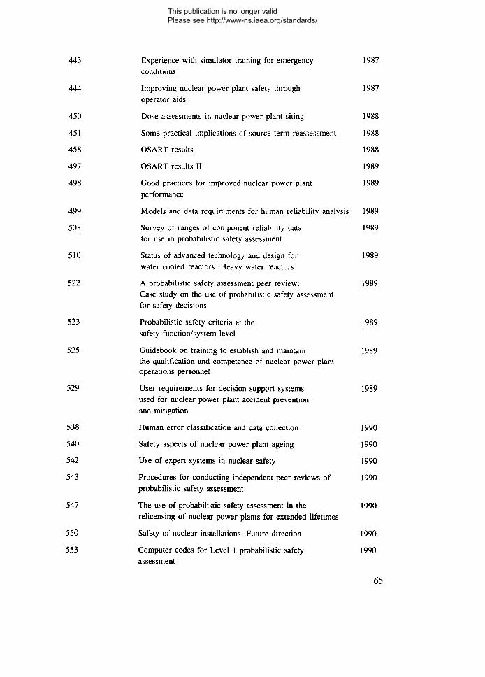
443 Experience with simulator training for emergency 1987conditions
444 Improving nuclear power plant safety through 1987operator aids
450 Dose assessments in nuclear power plant siting 1988
451 Some practical implications of source term reassessment 1988
458 OSART results 1988
497 OSART results II 1989
498 Good practices for improved nuclear power plant 1989performance
499 Models and data requirements for human reliability analysis 1989
508 Survey of ranges of component reliability data 1989for use in probabilistic safety assessment
510 Status of advanced technology and design for 1989water cooled reactors: Heavy water reactors
522 A probabilistic safety assessment peer review: 1989Case study on the use of probabilistic safety assessmentfor safety decisions
523 Probabilistic safety criteria at the 1989safety function/system level
525 Guidebook on training to establish and maintain 1989the qualification and competence of nuclear power plantoperations personnel
529 User requirements for decision support systems 1989used for nuclear power plant accident preventionand mitigation
538 Human error classification and data collection 1990
540 Safety aspects of nuclear power plant ageing 1990
542 Use of expert systems in nuclear safety 1990
543 Procedures for conducting independent peer reviews of 1990probabilistic safety assessment
547 The use of probabilistic safety assessment in the 1990relicensing of nuclear power plants for extended lifetimes
550 Safety of nuclear installations: Future direction 1990
553 Computer codes for Level 1 probabilistic safety 1990assessment
65
This publication is no longer valid Please see http://www-ns.iaea.org/standards/

561 Reviewing computer capabilities in nuclear power plants 1990
570 OSART mission highlights 1988-1989 1990
581 Safety implications of computerized process control 1991in nuclear power plants
586 Simulation of a loss of coolant accident with rupture 1991in the steam generator hot collector
590 Case study on the use of PSA methods: 1991Determining safety importance of systems and componentsat nuclear power plants
591 Case study on the use of PSA methods: 1991Backfitting decisions
592 Case study on the use of PSA methods: 1991Human reliability analysis
593 Case study on the use of PSA methods: 1991Station blackout risk at Millstone Unit 3
599 Use of probabilistic safety assessment to evaluate nuclear 1991power plant technical specifications
600 Numerical indicators of nuclear power plant safety 1991performance
605 OSART good practices: 1986-1989 1991
611 Use of plant specific PSA to evaluate incidents at 1991nuclear power plants
618 Human reliability data collection and modelling 1991
631 Reviewing reactor engineering and fuel handling: 1992Supplementary guidance and reference material forIAEA OSARTs
632 ASSET guidelines: Revised 1991 edition 1991
635 OSART guidelines: 1992 edition 1992
640 Ranking of safety issues for WWER-440 model 230 1992nuclear power plants
648 Procedures for conducting common cause failure analysis 1992in probabilistic safety assessment
658 Safety related maintenance in the framework of the 1992reliability centered maintenance concept
659 Reactor pressure vessel embrittlement 1992
66
This publication is no longer valid Please see http://www-ns.iaea.org/standards/
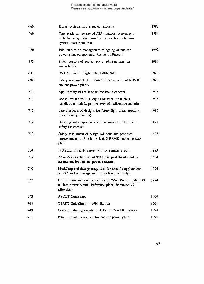
660 Expert systems in the nuclear industry 1992
669 Case study on the use of PSA methods: Assessment 1992of technical specifications for the reactor protectionsystem instrumentation
670 Pilot studies on management of ageing of nuclear 1992power plant components: Results of Phase I
672 Safety aspects of nuclear power plant automation 1992and robotics
681 OSART mission highlights: 1989-1990 1993
694 Safety assessment of proposed improvements of RBMK 1993nuclear power plants
710 Applicability of the leak before break concept 1993
711 Use of probab''istic safety assessment for nuclear 1993installations with large inventory of radioactive material
712 Safety aspects of designs for future light water reactors 1993(evolutionary reactors)
719 Defining initiating events for purposes of probabilistic 1993safety assessment
722 Safety assessment of design solutions and proposed 1993improvements to Smolensk Unit 3 RBMK nuclear powerplant
724 Probabilistic safety assessment for seismic events 1993
737 Advances in reliability analysis and probabilistic safety 1994assessment for nuclear power reactors
740 Modelling and data prerequisites for specific applications 1994of PSA in the management of nuclear plant safety
742 Design basis and design features of WWER-440 model 213 1994nuclear power plants: Reference plant: Bohunice V2(Slovakia)
743 ASCOT Guidelines 1994
744 OSART Guidelines — 1994 Edition 1994
749 Generic initiating events for PSA for WWER reactors 1994
751 PSA for shutdown mode for nuclear power plants 1994
67
This publication is no longer valid Please see http://www-ns.iaea.org/standards/
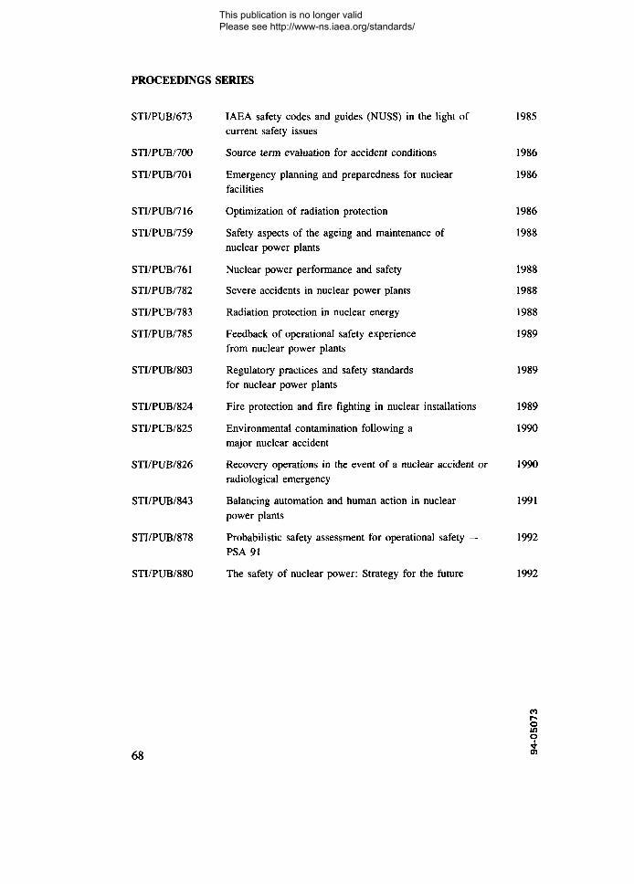
PROCEEDINGS SERIES
STI/PUB/673 IAEA safety codes and guides (NUSS) in the light of 1985current safety issues
STI/PUB/700 Source term evaluation for accident conditions 1986
STI/PUB/701 Emergency planning and preparedness for nuclear 1986facilities
STI/PUB/716 Optimization of radiation protection 1986
STI/PUB/759 Safety aspects of the ageing and maintenance of 1988nuclear power plants
STI/PUB/761 Nuclear power performance and safety 1988
STI/PUB/782 Severe accidents in nuclear power plants 1988
STI/PUB/783 Radiation protection in nuclear energy 1988
STI/PUB/785 Feedback of operational safety experience 1989from nuclear power plants
STI/PUB/803 Regulatory practices and safety standards 1989for nuclear power plants
STI/PUB/824 Fire protection and fire fighting in nuclear installations 1989
STI/PUB/825 Environmental contamination following a 1990major nuclear accident
STT/PUB/826 Recovery operations in the event of a nuclear accident or 1990radiological emergency
STI/PUB/843 Balancing automation and human action in nuclear 1991power plants
STI/PUB/878 Probabilistic safety assessment for operational safety — 1992PSA 91
STI/PUB/880 The safety of nuclear power: Strategy for the future 1992
68
COr~oino
*
This publication is no longer valid Please see http://www-ns.iaea.org/standards/
HOW TO ORDER IAEA PUBLICATIONS
•& In the United States of America and Canada, the exclusive sales agent forIAEA publications, to whom all orders and inquiries shouldbe addressed, is:
UNIPUB, 4611-F Assembly Drive, Lanham, MD 20706-4391, USA
%r In the following countries IAEA publications may be purchased from the sourceslisted below, or from major local booksellers. Payment maybe made in local currency or with UNESCO coupons.
ARGENTINA
AUSTRALIABELGIUM
CHILE
CHINA
FRANCE
GERMANY
HUNGARYINDIA
ISRAELITALY
JAPANNETHERLANDS
PAKISTANPOLAND
ROMANIARUSSIAN FEDERATION
SLOVAK REPUBLICSOUTH AFRICA
SPAIN
SWEDENUNITED KINGDOM
YUGOSLAVIA
Comisidn Nacional de Energia Atdmica, Avenida del Libertador 8250,RA-1429 Buenos AiresHunter Publications, 58A Gipps Street, Collingwood, Victoria 3066Service Courrier UNESCO, 202, Avenue du Roi, B-1060 BrusselsComisidn Chilena de Energia Nuclear, Venta de Publicaciones,Amunategui 95, Casilla 188-D, SantiagoIAEA Publications in Chinese:China Nuclear Energy Industry Corporation, Translation Section,P.O. Box 2103, BeijingIAEA Publications other than in Chinese:China National Publications Import & Export Corporation,Deutsche Abteilung, P.O. Box 88, BeijingOffice International de Documentation et Librairie, 48, rue Gay-Lussac,F-75240 Paris Cedex 05UNO-Verlag, Vertriebs- und Verlags GmbH, Dag Hammarskjold-Haus,Poppelsdorfer Allee 55, D-53115 BonnLibrotrade Ltd., Book Import, P.O. Box 126, H-1656 BudapestOxford Book and Stationery Co., Scindia House, New Delhi-110 001YOZMOT Literature Ltd., P.O. Box 56055, IL-61560 Tel AvivLibreria Scientifica Dott. Lucio di Biasio "AEIOU",Via Coronelli 6, 1-20146 MilanMaruzen Company, Ltd, P.O. Box 5050, 10O-31 Tokyo InternationalMartinus Nijhoff International, P.O. Box 269, NL-2501 AX The HagueSwets and Zeitlinger b.v., P.O. Box 830, NL-2610 SZ LisseMirza Book Agency, 65, Shahrah Quaid-e-Azam, P.O. Box 729, Lahore 3Ars Polona, Foreign Trade Enterprise,Krakowskie Przedmiescie 7, PL-00-068 Warsawllexim, P.O. Box 136-137, BucharestMezhdunarodnaya Kniga, Sovinkniga-EA,Dimitrova 39, SU-113 095 MoscowAlfa Publishers, Hurbanovo namestie 3, SQ-815 89 BratislavaVan Schaik Bookstore (Pty) Ltd, P.O. Box 724, Pretoria 0001Diaz de Santos, Lagasca 95, E-28006 MadridDiaz de Santos, Balmes 417, E-08022 BarcelonaFritzes Information Centre, S-106 47 StockholmHMSO, Publications Centre, Agency Section,51 Nine Elms Lane, London SW8 SDRJugoslovenska Knjiga, Terazije 27, P.O. Box 36, YU-11001 Belgrade
•fr •& Orders (except for customers in Canada and the USA) and requests for informationmay also be addressed directly to:
Sales and Promotion UnitInternational Atomic Energy AgencyWagramerstrasse 5, P.O. Box 100, A-1400 Vienna, Austria
This publication is no longer valid Please see http://www-ns.iaea.org/standards/

ISBN 92-0-105194-8ISSN 0074-1892
This publication is no longer valid Please see http://www-ns.iaea.org/standards/