Embed Size (px)
Citation preview
125
EN 3
.551
.23/
06.1
8
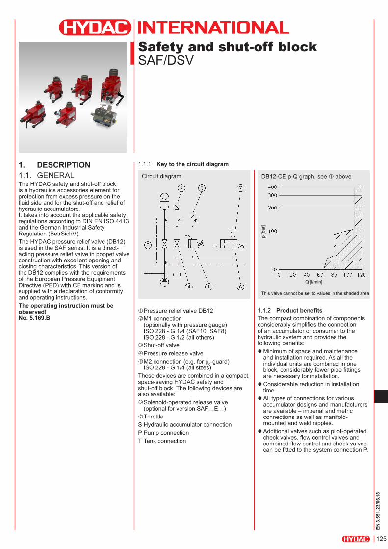
1. DESCRIPTION1.1. GENERALThe HYDAC safety and shut-off block is a hydraulics accessories element for protection from excess pressure on the fluid side and for the shut-off and relief of hydraulic accumulators. It takes into account the applicable safety regulations according to DIN EN ISO 4413 and the German Industrial Safety Regulation (BetrSichV).The HYDAC pressure relief valve (DB12) is used in the SAF series. It is a direct-acting pressure relief valve in poppet valve construction with excellent opening and closing characteristics. This version of the DB12 complies with the requirements of the European Pressure Equipment Directive (PED) with CE marking and is supplied with a declaration of conformity and operating instructions.The operating instruction must be observed! No. 5.169.B
Safety and shut-off blockSAF/DSV
Circuit diagram
1.1.1 Key to the circuit diagram
1.1.2 Product benefitsThe compact combination of components considerably simplifies the connection of an accumulator or consumer to the hydraulic system and provides the following benefits:
zMinimum of space and maintenance and installation required. As all the individual units are combined in one block, considerably fewer pipe fittings are necessary for installation. zConsiderable reduction in installation time. zAll types of connections for various accumulator designs and manufacturers are available – imperial and metric connections as well as manifold-mounted and weld nipples. zAdditional valves such as pilot-operated check valves, flow control valves and combined flow control and check valves can be fitted to the system connection P.
Q [l/min]
p [b
ar]
DB12-CE p-Q graph, see above
This valve cannot be set to values in the shaded area
Pressure relief valve DB12 M1 connection
(optionally with pressure gauge) ISO 228 - G 1/4 (SAF10, SAF8) ISO 228 - G 1/2 (all others)
Shut-off valve Pressure release valve M2 connection (e.g. for p0-guard)
ISO 228 - G 1/4 (all sizes)These devices are combined in a compact, space-saving HYDAC safety and shut-off block. The following devices are also available: Solenoid-operated release valve
(optional for version SAF…E…) ThrottleS Hydraulic accumulator connectionP Pump connectionT Tank connection
126
EN 3
.551
.23/
06.1
8
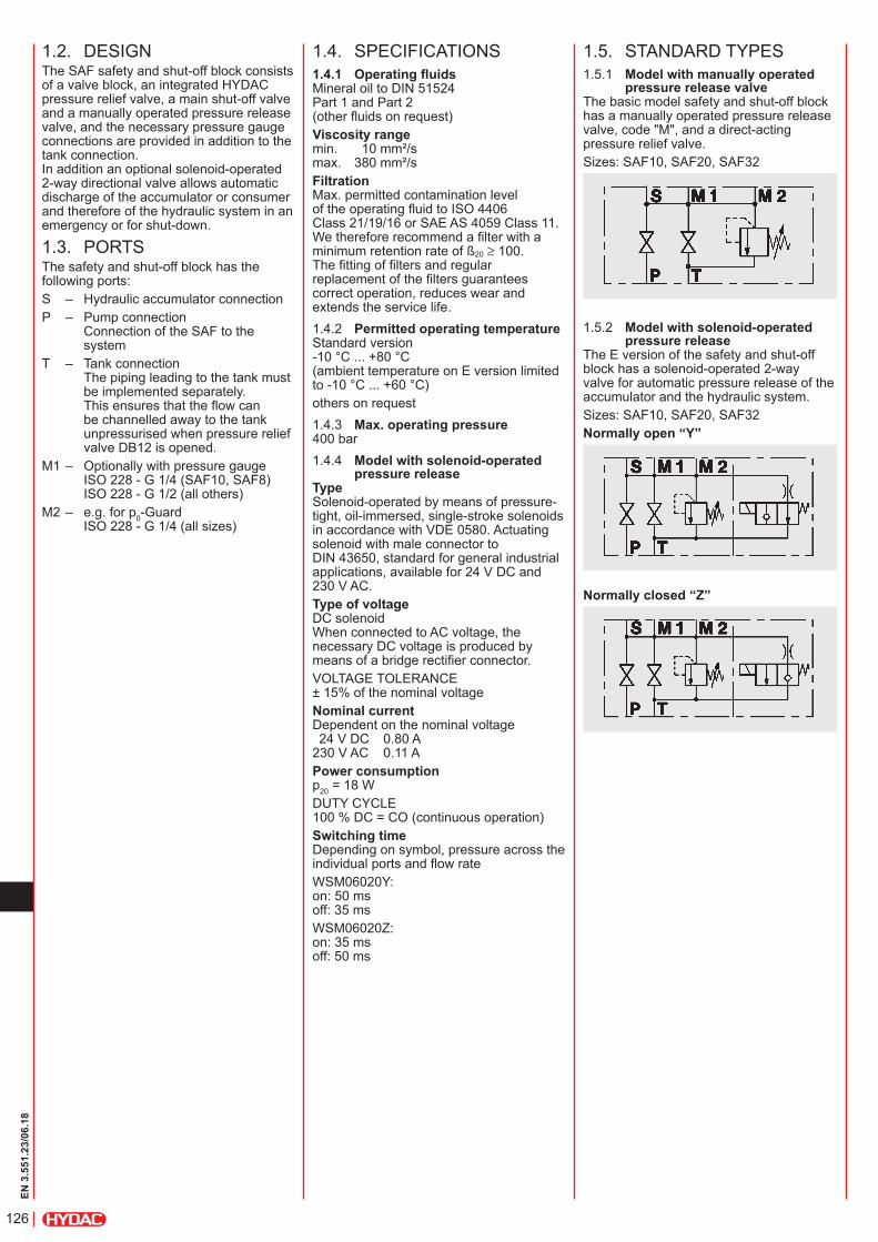
1.2. DESIGNThe SAF safety and shut-off block consists of a valve block, an integrated HYDAC pressure relief valve, a main shut-off valve and a manually operated pressure release valve, and the necessary pressure gauge connections are provided in addition to the tank connection. In addition an optional solenoid-operated 2-way directional valve allows automatic discharge of the accumulator or consumer and therefore of the hydraulic system in an emergency or for shut-down.
1.3. PORTSThe safety and shut-off block has the following ports:S – Hydraulic accumulator connectionP – Pump connection
Connection of the SAF to the system
T – Tank connection The piping leading to the tank must be implemented separately. This ensures that the flow can be channelled away to the tank unpressurised when pressure relief valve DB12 is opened.
M1 – Optionally with pressure gauge ISO 228 - G 1/4 (SAF10, SAF8) ISO 228 - G 1/2 (all others)
M2 – e.g. for p0-Guard ISO 228 - G 1/4 (all sizes)
1.4. SPECIFICATIONS1.4.1 Operating fluidsMineral oil to DIN 51524 Part 1 and Part 2 (other fluids on request)Viscosity range min. 10 mm²/s max. 380 mm²/sFiltration Max. permitted contamination level of the operating fluid to ISO 4406 Class 21/19/16 or SAE AS 4059 Class 11. We therefore recommend a filter with a minimum retention rate of ß20 ≥ 100. The fitting of filters and regular replacement of the filters guarantees correct operation, reduces wear and extends the service life.1.4.2 Permitted operating temperatureStandard version -10 °C ... +80 °C (ambient temperature on E version limited to -10 °C ... +60 °C)others on request1.4.3 Max. operating pressure400 bar1.4.4 Model with solenoid-operated
pressure releaseType Solenoid-operated by means of pressure-tight, oil-immersed, single-stroke solenoids in accordance with VDE 0580. Actuating solenoid with male connector to DIN 43650, standard for general industrial applications, available for 24 V DC and 230 V AC.Type of voltage DC solenoid When connected to AC voltage, the necessary DC voltage is produced by means of a bridge rectifier connector.VOLTAGE TOLERANCE ± 15% of the nominal voltageNominal current Dependent on the nominal voltage 24 V DC 0.80 A 230 V AC 0.11 APower consumption p20 = 18 WDUTY CYCLE 100 % DC = CO (continuous operation)Switching time Depending on symbol, pressure across the individual ports and flow rateWSM06020Y: on: 50 ms off: 35 msWSM06020Z: on: 35 ms off: 50 ms
1.5. STANDARD TYPES1.5.1 Model with manually operated
pressure release valveThe basic model safety and shut-off block has a manually operated pressure release valve, code "M", and a direct-acting pressure relief valve.Sizes: SAF10, SAF20, SAF32
1.5.2 Model with solenoid-operated pressure release
The E version of the safety and shut-off block has a solenoid-operated 2-way valve for automatic pressure release of the accumulator and the hydraulic system.Sizes: SAF10, SAF20, SAF32Normally open “Y”
Normally closed “Z”
127
EN 3
.551
.23/
06.1
8
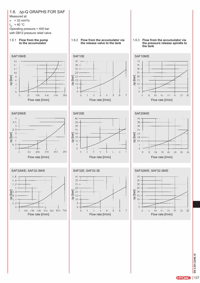
1.6. ∆p-Q GRAPHS FOR SAFMeasured at:ν = 32 mm²/stoil = 40 °COperating pressure = 400 barwith DB12 pressure relief valve
1.6.1 Flow from the pump to the accumulator
1.6.2 Flow from the accumulator via the release valve to the tank
1.6.3 Flow from the accumulator via the pressure release spindle to the tank
SAF10M/E
∆p [b
ar]
Flow rate [l/min]
SAF10E SAF10M/E
∆p [b
ar]
Flow rate [l/min]
∆p [b
ar]
Flow rate [l/min]
SAF20M/E
∆p [b
ar]
Flow rate [l/min]
SAF20E SAF20M/E
∆p [b
ar]
Flow rate [l/min]
∆p [b
ar]
Flow rate [l/min]
SAF32M/E; SAF32-3M/E
∆p [b
ar]
Flow rate [l/min]
SAF32E; SAF32-3E SAF32M/E; SAF32-3M/E
∆p [b
ar]
Flow rate [l/min]
∆p [b
ar]
Flow rate [l/min]
128
EN 3
.551
.23/
06.1
8
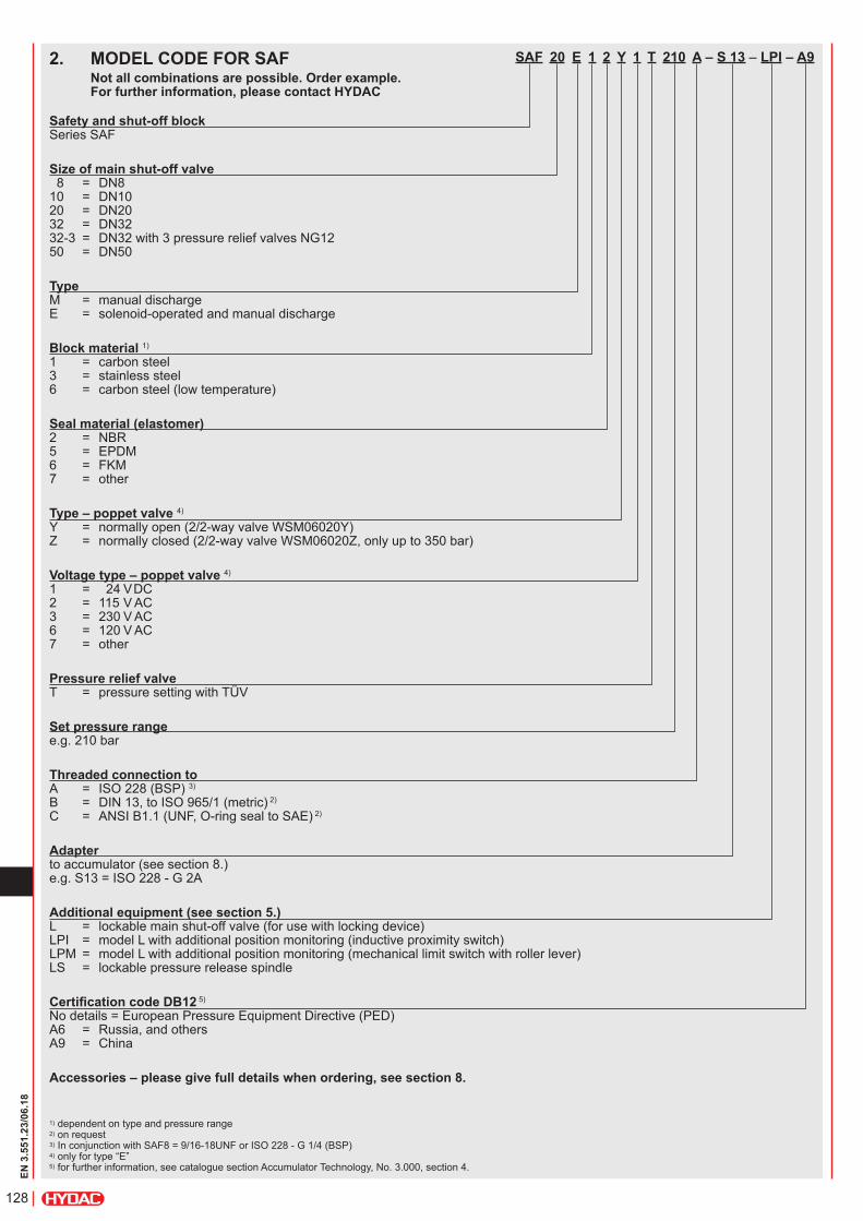
SAF 20 E 1 2 Y 1 T 210 A – S 13 – LPI – A9
Safety and shut-off block Series SAF
Size of main shut-off valve 8 = DN8 10 = DN10 20 = DN20 32 = DN32 32-3 = DN32 with 3 pressure relief valves NG12 50 = DN50
Type M = manual discharge E = solenoid-operated and manual discharge
Block material 1) 1 = carbon steel 3 = stainless steel 6 = carbon steel (low temperature)
Seal material (elastomer) 2 = NBR 5 = EPDM 6 = FKM 7 = other
Type – poppet valve 4) Y = normally open (2/2-way valve WSM06020Y) Z = normally closed (2/2-way valve WSM06020Z, only up to 350 bar)
Voltage type – poppet valve 4) 1 = 24 V DC 2 = 115 V AC 3 = 230 V AC 6 = 120 V AC 7 = other
Pressure relief valve T = pressure setting with TÜV
Set pressure range e.g. 210 bar
Threaded connection to A = ISO 228 (BSP) 3) B = DIN 13, to ISO 965/1 (metric) 2)
C = ANSI B1.1 (UNF, O-ring seal to SAE) 2)
Adapter to accumulator (see section 8.) e.g. S13 = ISO 228 - G 2A
Additional equipment (see section 5.) L = lockable main shut-off valve (for use with locking device) LPI = model L with additional position monitoring (inductive proximity switch) LPM = model L with additional position monitoring (mechanical limit switch with roller lever) LS = lockable pressure release spindle
Certification code DB12 5) No details = European Pressure Equipment Directive (PED) A6 = Russia, and others A9 = China
Accessories – please give full details when ordering, see section 8.
2. MODEL CODE FOR SAFNot all combinations are possible. Order example. For further information, please contact HYDAC
1) dependent on type and pressure range 2) on request3) In conjunction with SAF8 = 9/16-18UNF or ISO 228 - G 1/4 (BSP)4) only for type “E”5) for further information, see catalogue section Accumulator Technology, No. 3.000, section 4.
129
EN 3
.551
.23/
06.1
8
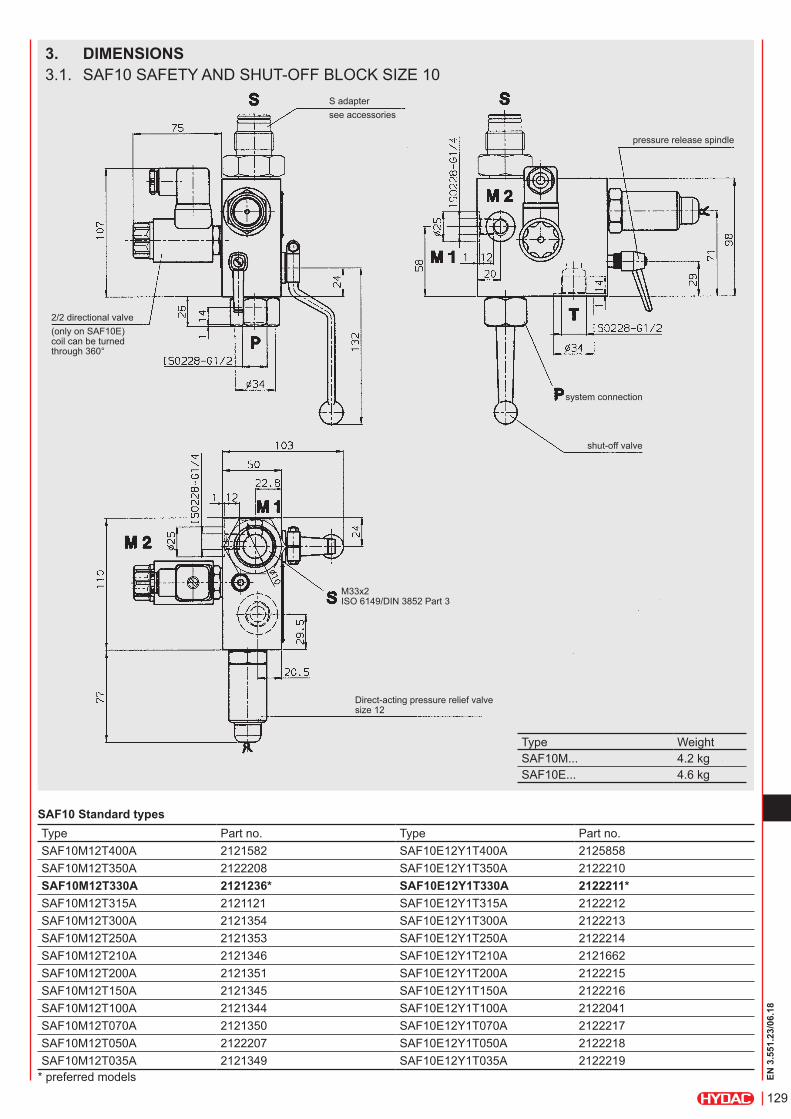
3. DIMENSIONS3.1. SAF10 SAFETY AND SHUT-OFF BLOCK SIZE 10
S adaptersee accessories
2/2 directional valve(only on SAF10E) coil can be turned through 360°
pressure release spindle
system connection
shut-off valve
M33x2 ISO 6149/DIN 3852 Part 3
Direct-acting pressure relief valve size 12
SAF10 Standard typesType Part no. Type Part no.SAF10M12T400A 2121582 SAF10E12Y1T400A 2125858SAF10M12T350A 2122208 SAF10E12Y1T350A 2122210SAF10M12T330A 2121236* SAF10E12Y1T330A 2122211*SAF10M12T315A 2121121 SAF10E12Y1T315A 2122212SAF10M12T300A 2121354 SAF10E12Y1T300A 2122213SAF10M12T250A 2121353 SAF10E12Y1T250A 2122214SAF10M12T210A 2121346 SAF10E12Y1T210A 2121662SAF10M12T200A 2121351 SAF10E12Y1T200A 2122215SAF10M12T150A 2121345 SAF10E12Y1T150A 2122216SAF10M12T100A 2121344 SAF10E12Y1T100A 2122041SAF10M12T070A 2121350 SAF10E12Y1T070A 2122217SAF10M12T050A 2122207 SAF10E12Y1T050A 2122218SAF10M12T035A 2121349 SAF10E12Y1T035A 2122219
* preferred models
Type WeightSAF10M... 4.2 kgSAF10E... 4.6 kg
130
EN 3
.551
.23/
06.1
8
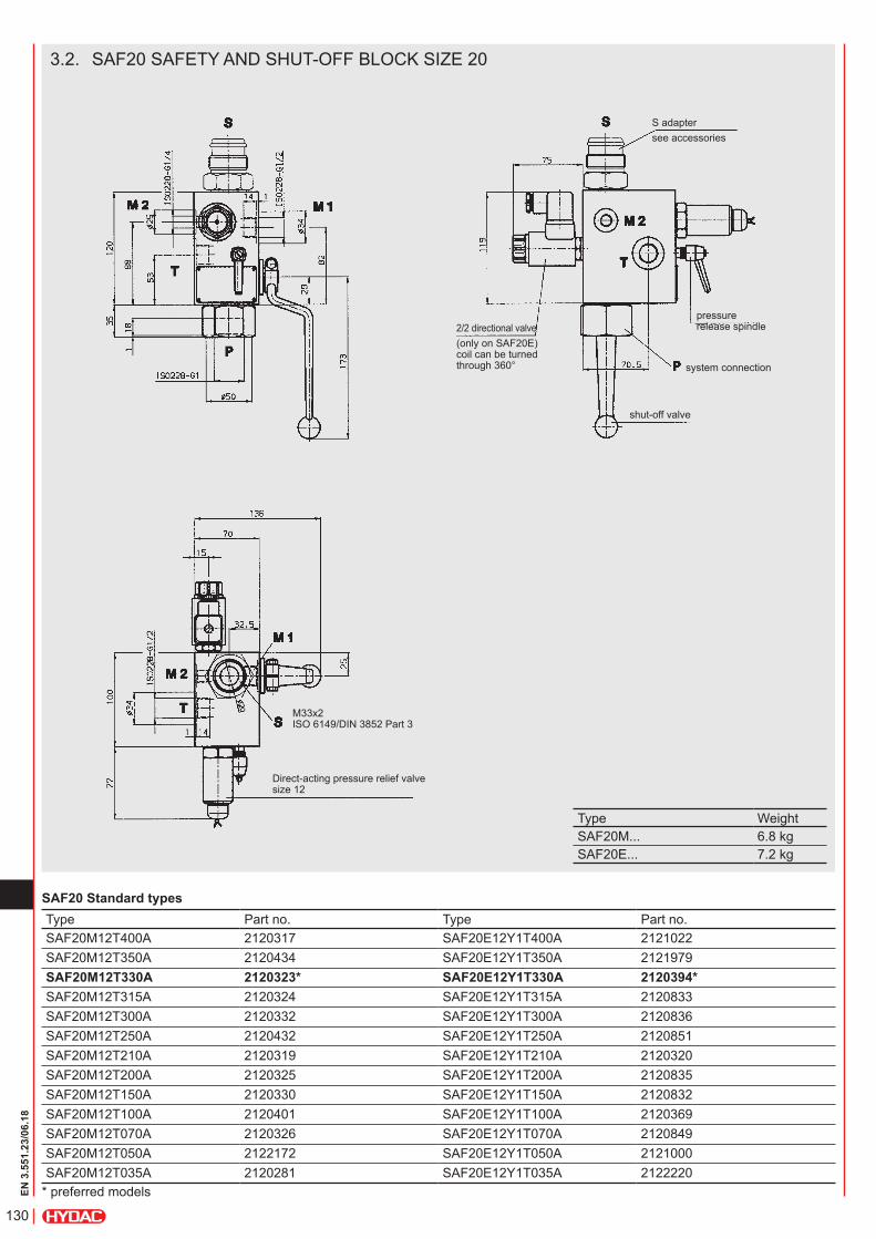
3.2. SAF20 SAFETY AND SHUT-OFF BLOCK SIZE 20
S adaptersee accessories
pressure release spindle
system connection
shut-off valve
2/2 directional valve(only on SAF20E) coil can be turned through 360°
M33x2 ISO 6149/DIN 3852 Part 3
Direct-acting pressure relief valve size 12
SAF20 Standard typesType Part no. Type Part no.SAF20M12T400A 2120317 SAF20E12Y1T400A 2121022SAF20M12T350A 2120434 SAF20E12Y1T350A 2121979SAF20M12T330A 2120323* SAF20E12Y1T330A 2120394*SAF20M12T315A 2120324 SAF20E12Y1T315A 2120833SAF20M12T300A 2120332 SAF20E12Y1T300A 2120836SAF20M12T250A 2120432 SAF20E12Y1T250A 2120851SAF20M12T210A 2120319 SAF20E12Y1T210A 2120320SAF20M12T200A 2120325 SAF20E12Y1T200A 2120835SAF20M12T150A 2120330 SAF20E12Y1T150A 2120832SAF20M12T100A 2120401 SAF20E12Y1T100A 2120369SAF20M12T070A 2120326 SAF20E12Y1T070A 2120849SAF20M12T050A 2122172 SAF20E12Y1T050A 2121000SAF20M12T035A 2120281 SAF20E12Y1T035A 2122220
* preferred models
Type WeightSAF20M... 6.8 kgSAF20E... 7.2 kg
131
EN 3
.551
.23/
06.1
8
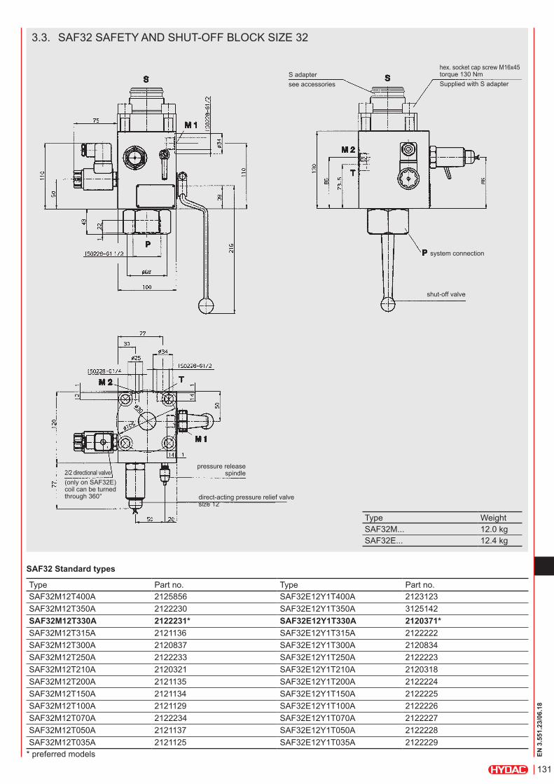
3.3. SAF32 SAFETY AND SHUT-OFF BLOCK SIZE 32
S adaptersee accessories
hex. socket cap screw M16x45 torque 130 NmSupplied with S adapter
system connection
shut-off valve
pressure release spindle
direct-acting pressure relief valve size 12
2/2 directional valve(only on SAF32E) coil can be turned through 360°
SAF32 Standard types
Type Part no. Type Part no.SAF32M12T400A 2125856 SAF32E12Y1T400A 2123123SAF32M12T350A 2122230 SAF32E12Y1T350A 3125142SAF32M12T330A 2122231* SAF32E12Y1T330A 2120371*SAF32M12T315A 2121136 SAF32E12Y1T315A 2122222SAF32M12T300A 2120837 SAF32E12Y1T300A 2120834SAF32M12T250A 2122233 SAF32E12Y1T250A 2122223SAF32M12T210A 2120321 SAF32E12Y1T210A 2120318SAF32M12T200A 2121135 SAF32E12Y1T200A 2122224SAF32M12T150A 2121134 SAF32E12Y1T150A 2122225SAF32M12T100A 2121129 SAF32E12Y1T100A 2122226SAF32M12T070A 2122234 SAF32E12Y1T070A 2122227SAF32M12T050A 2121137 SAF32E12Y1T050A 2122228SAF32M12T035A 2121125 SAF32E12Y1T035A 2122229
* preferred models
Type WeightSAF32M... 12.0 kgSAF32E... 12.4 kg
132
EN 3
.551
.23/
06.1
8
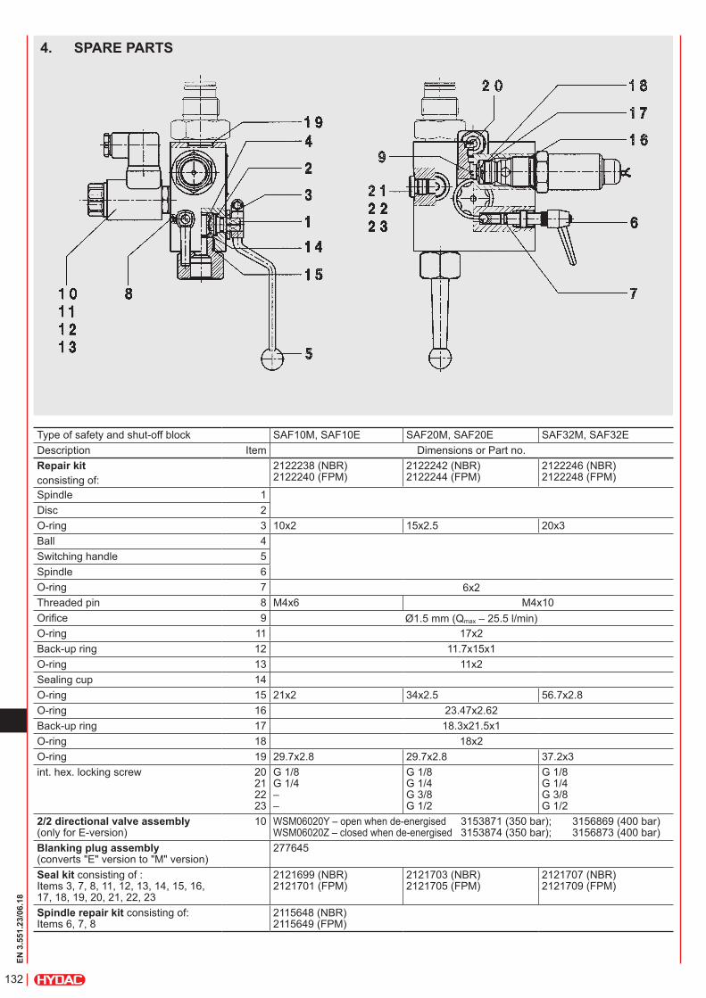
4. SPARE PARTS
Type of safety and shut-off block SAF10M, SAF10E SAF20M, SAF20E SAF32M, SAF32EDescription Item Dimensions or Part no.Repair kitconsisting of:
2122238 (NBR) 2122240 (FPM)
2122242 (NBR) 2122244 (FPM)
2122246 (NBR) 2122248 (FPM)
Spindle 1Disc 2O-ring 3 10x2 15x2.5 20x3Ball 4Switching handle 5Spindle 6O-ring 7 6x2Threaded pin 8 M4x6 M4x10Orifice 9 Ø1.5 mm (Qmax – 25.5 l/min)O-ring 11 17x2Back-up ring 12 11.7x15x1O-ring 13 11x2Sealing cup 14O-ring 15 21x2 34x2.5 56.7x2.8O-ring 16 23.47x2.62Back-up ring 17 18.3x21.5x1O-ring 18 18x2O-ring 19 29.7x2.8 29.7x2.8 37.2x3int. hex. locking screw 20
21 22 23
G 1/8 G 1/4 – –
G 1/8 G 1/4 G 3/8 G 1/2
G 1/8 G 1/4 G 3/8 G 1/2
2/2 directional valve assembly(only for E-version)
10 WSM06020Y – open when de-energised 3153871 (350 bar); 3156869 (400 bar) WSM06020Z – closed when de-energised 3153874 (350 bar); 3156873 (400 bar)
Blanking plug assembly(converts "E" version to "M" version)
277645
Seal kit consisting of : Items 3, 7, 8, 11, 12, 13, 14, 15, 16, 17, 18, 19, 20, 21, 22, 23
2121699 (NBR) 2121701 (FPM)
2121703 (NBR) 2121705 (FPM)
2121707 (NBR) 2121709 (FPM)
Spindle repair kit consisting of: Items 6, 7, 8
2115648 (NBR) 2115649 (FPM)
133
EN 3
.551
.23/
06.1
8
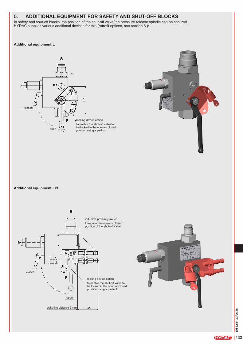
5. ADDITIONAL EQUIPMENT FOR SAFETY AND SHUT-OFF BLOCKSIn safety and shut-off blocks, the position of the shut-off valve/the pressure release spindle can be secured. HYDAC supplies various additional devices for this (retrofit options, see section 8.):
Additional equipment LPI
Additional equipment L
inductive proximity switchto monitor the open or closed position of the shut-off valve
switching distance 2 mm
locking device optionto enable the shut-off valve to be locked in the open or closed position using a padlock
open
closed
closed
open
locking device optionto enable the shut-off valve to be locked in the open or closed position using a padlock
134
EN 3
.551
.23/
06.1
8
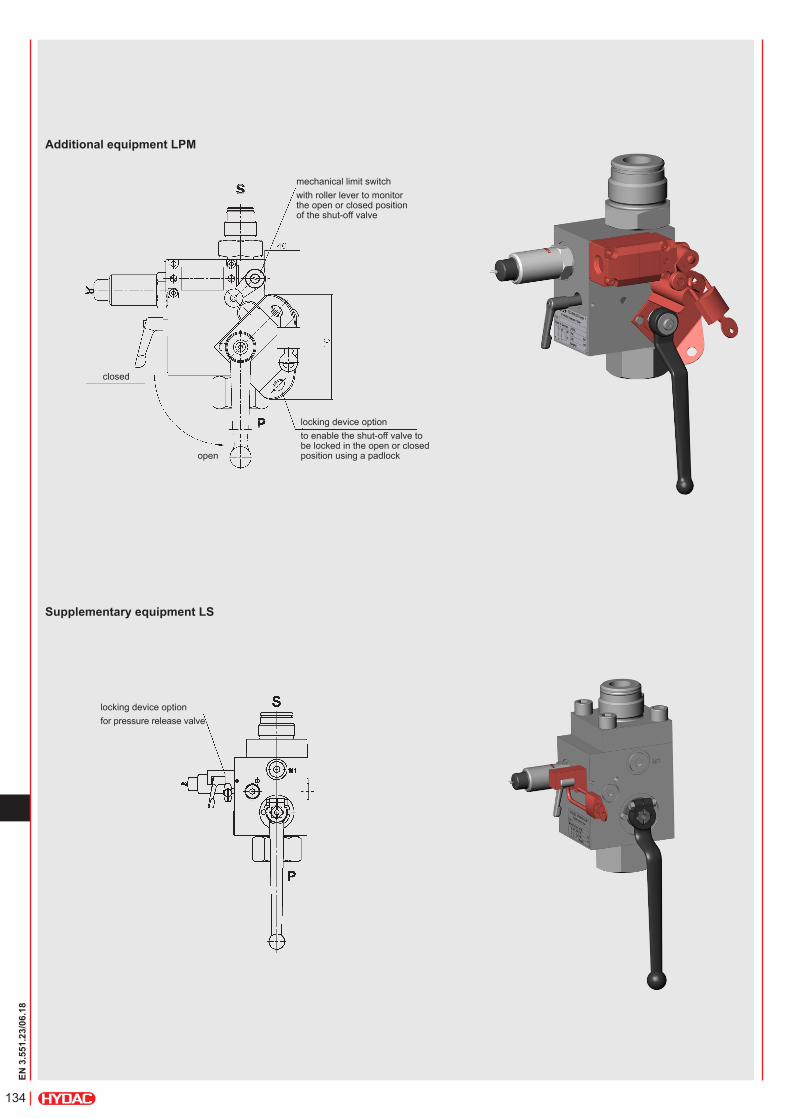
Supplementary equipment LS
Additional equipment LPM
mechanical limit switchwith roller lever to monitor the open or closed position of the shut-off valve
locking device optionto enable the shut-off valve to be locked in the open or closed position using a padlock
locking device optionfor pressure release valve
open
closed
135
EN 3
.551
.23/
06.1
8
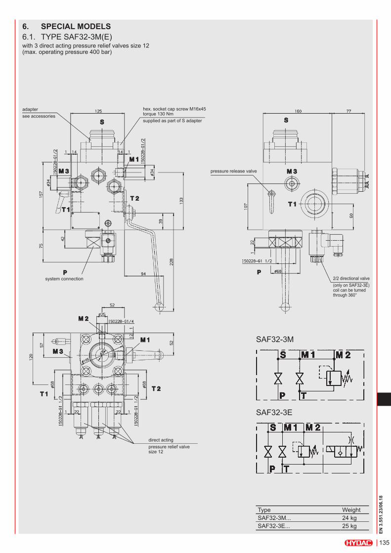
6. SPECIAL MODELS6.1. TYPE SAF32-3M(E)with 3 direct acting pressure relief valves size 12 (max. operating pressure 400 bar)
hex. socket cap screw M16x45 torque 130 Nmsupplied as part of S adapter
adaptersee accessories
system connection
pressure release valve
2/2 directional valve(only on SAF32-3E) coil can be turned through 360°
direct actingpressure relief valve size 12
SAF32-3M
SAF32-3E
Type WeightSAF32-3M... 24 kgSAF32-3E... 25 kg
136
EN 3
.551
.23/
06.1
8
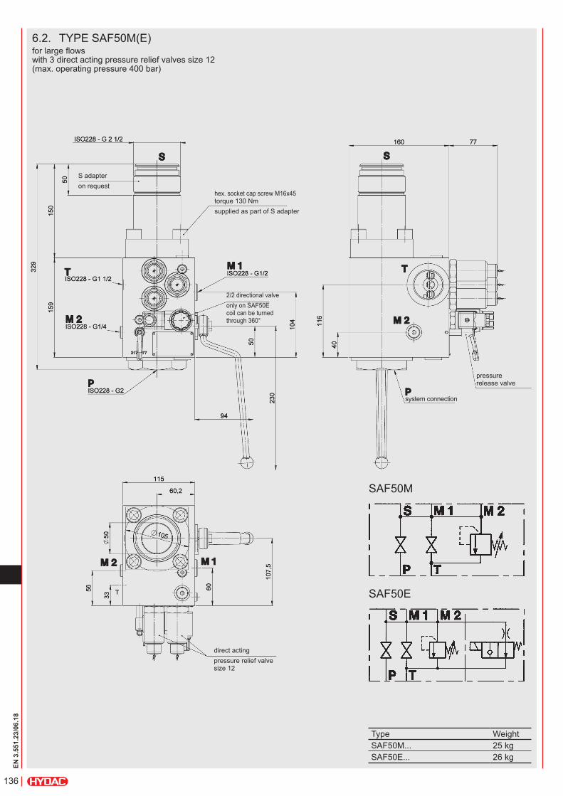
6.2. TYPE SAF50M(E)for large flows with 3 direct acting pressure relief valves size 12 (max. operating pressure 400 bar)
system connection
pressure release valve
hex. socket cap screw M16x45 torque 130 Nmsupplied as part of S adapter
S adapteron request
2/2 directional valveonly on SAF50E coil can be turned through 360°
direct actingpressure relief valve size 12
SAF50M
SAF50E
Type WeightSAF50M... 25 kgSAF50E... 26 kg
137
EN 3
.551
.23/
06.1
8
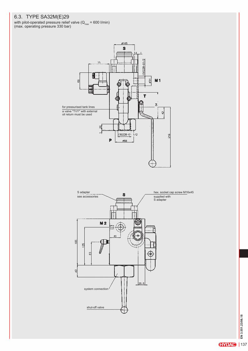
6.3. TYPE SA32M(E)29with pilot-operated pressure relief valve (Qmax = 600 l/min) (max. operating pressure 330 bar)
for pressurised tank linesa valve "TVY" with external oil return must be used
S adaptersee accessories
hex. socket cap screw M16x45supplied with S adapter
system connection
shut-off valve
138
EN 3
.551
.23/
06.1
8
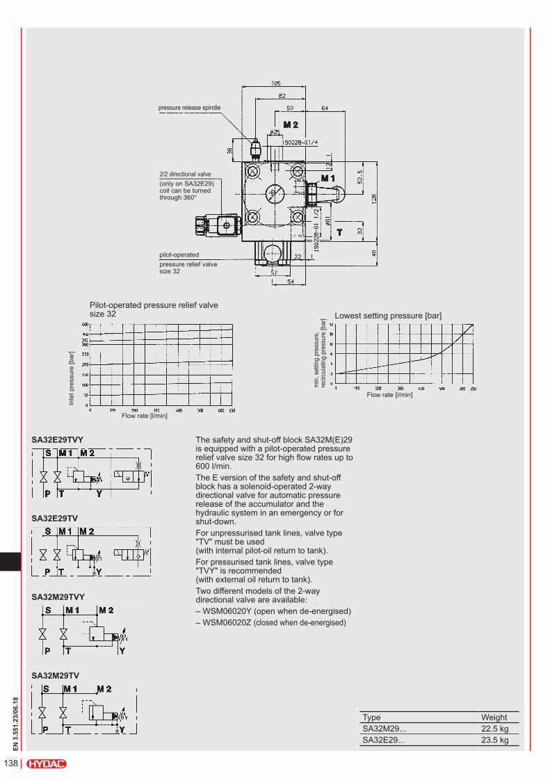
pressure release spindle
2/2 directional valve(only on SA32E29) coil can be turned through 360°
pilot-operatedpressure relief valve size 32
Pilot-operated pressure relief valve size 32
Inle
t pre
ssur
e [b
ar]
Flow rate [l/min]
Lowest setting pressure [bar]m
in. s
ettin
g pr
essu
re,
recir
cula
ting
pres
sure
[bar
]
Flow rate [l/min]
SA32E29TV
SA32E29TVY The safety and shut-off block SA32M(E)29 is equipped with a pilot-operated pressure relief valve size 32 for high flow rates up to 600 l/min.The E version of the safety and shut-off block has a solenoid-operated 2-way directional valve for automatic pressure release of the accumulator and the hydraulic system in an emergency or for shut-down.For unpressurised tank lines, valve type "TV" must be used (with internal pilot-oil return to tank).For pressurised tank lines, valve type "TVY" is recommended (with external oil return to tank). Two different models of the 2-way directional valve are available:– WSM06020Y (open when de-energised)– WSM06020Z (closed when de-energised)
SA32M29TVY
SA32M29TV
Type WeightSA32M29... 22.5 kgSA32E29... 23.5 kg
139
EN 3
.551
.23/
06.1
8
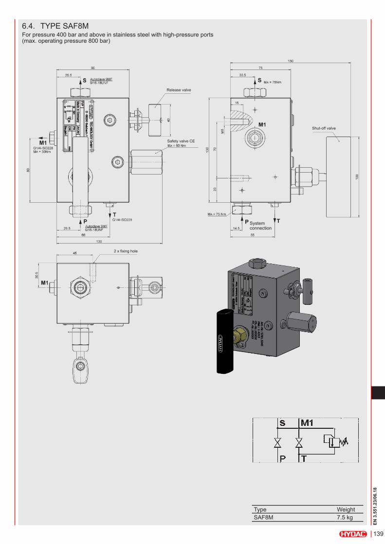
Type WeightSAF8M 7.5 kg
6.4. TYPE SAF8MFor pressure 400 bar and above in stainless steel with high-pressure ports (max. operating pressure 800 bar)
Release valve
Safety valve CE
2 x fixing hole
Shut-off valve
System connection
140
EN 3
.551
.23/
06.1
8
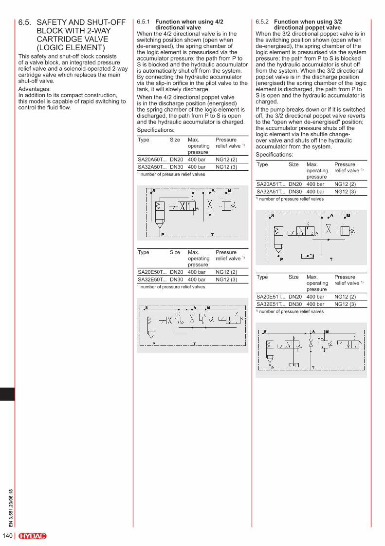
6.5.1 Function when using 4/2 directional valve
When the 4/2 directional valve is in the switching position shown (open when de-energised), the spring chamber of the logic element is pressurised via the accumulator pressure; the path from P to S is blocked and the hydraulic accumulator is automatically shut off from the system. By connecting the hydraulic accumulator via the slip-in orifice in the pilot valve to the tank, it will slowly discharge.When the 4/2 directional poppet valve is in the discharge position (energised) the spring chamber of the logic element is discharged, the path from P to S is open and the hydraulic accumulator is charged.Specifications:Type Size Max.
operating pressure
Pressure relief valve 1)
SA20A50T... DN20 400 bar NG12 (2)SA32A50T... DN30 400 bar NG12 (3)
1) number of pressure relief valves
Type Size Max. operating pressure
Pressure relief valve 1)
SA20E50T... DN20 400 bar NG12 (2)SA32E50T... DN30 400 bar NG12 (3)
1) number of pressure relief valves
6.5.2 Function when using 3/2 directional poppet valve
When the 3/2 directional poppet valve is in the switching position shown (open when de-energised), the spring chamber of the logic element is pressurised via the system pressure; the path from P to S is blocked and the hydraulic accumulator is shut off from the system. When the 3/2 directional poppet valve is in the discharge position (energised) the spring chamber of the logic element is discharged, the path from P to S is open and the hydraulic accumulator is charged.If the pump breaks down or if it is switched off, the 3/2 directional poppet valve reverts to the "open when de-energised" position; the accumulator pressure shuts off the logic element via the shuttle change-over valve and shuts off the hydraulic accumulator from the system.Specifications:Type Size Max.
operating pressure
Pressure relief valve 1)
SA20A51T... DN20 400 bar NG12 (2)SA32A51T... DN30 400 bar NG12 (3)
1) number of pressure relief valves
Type Size Max. operating pressure
Pressure relief valve 1)
SA20E51T... DN20 400 bar NG12 (2)SA32E51T... DN30 400 bar NG12 (3)
1) number of pressure relief valves
6.5. SAFETY AND SHUT-OFF BLOCK WITH 2-WAY CARTRIDGE VALVE (LOGIC ELEMENT)
This safety and shut-off block consists of a valve block, an integrated pressure relief valve and a solenoid-operated 2-way cartridge valve which replaces the main shut-off valve.Advantages: In addition to its compact construction, this model is capable of rapid switching to control the fluid flow.
141
EN 3
.551
.23/
06.1
8
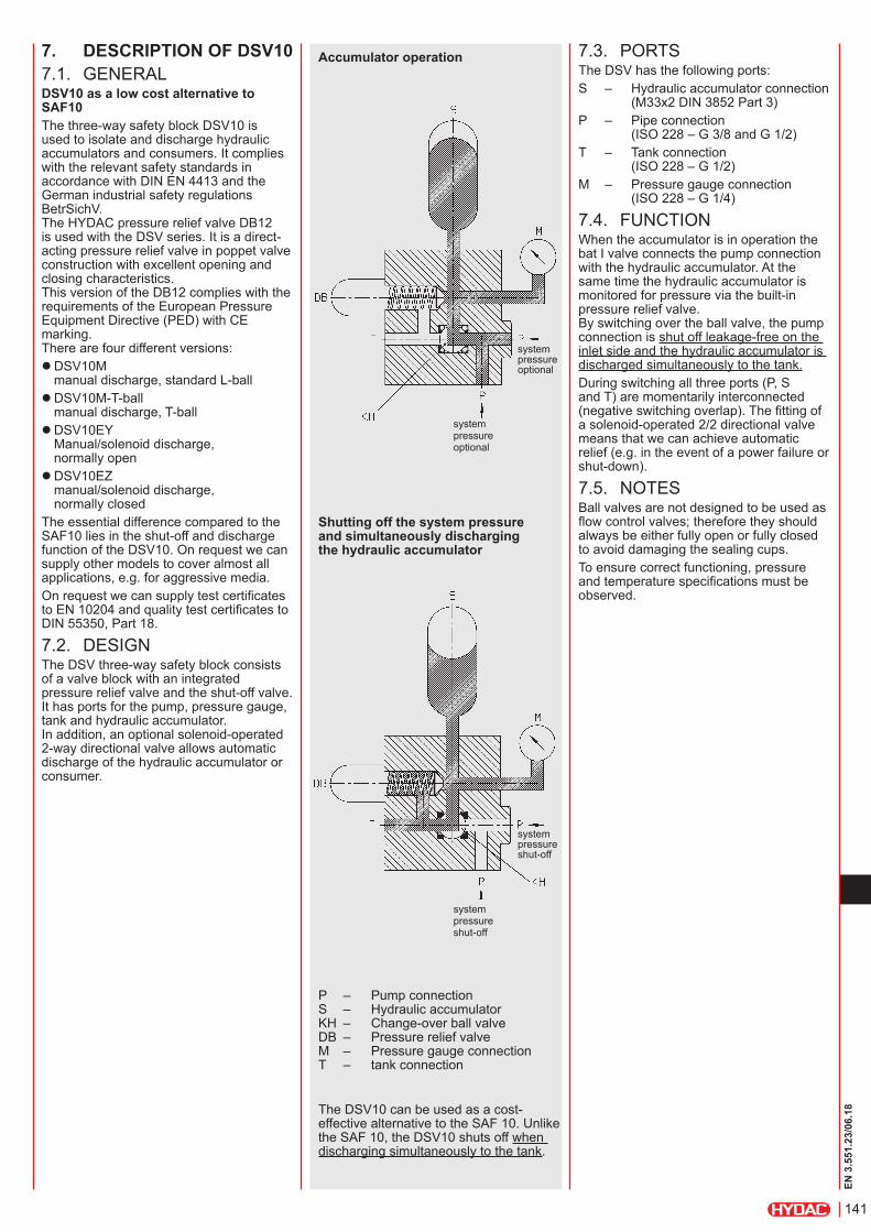
7. DESCRIPTION OF DSV107.1. GENERALDSV10 as a low cost alternative to SAF10The three-way safety block DSV10 is used to isolate and discharge hydraulic accumulators and consumers. It complies with the relevant safety standards in accordance with DIN EN 4413 and the German industrial safety regulations BetrSichV. The HYDAC pressure relief valve DB12 is used with the DSV series. It is a direct-acting pressure relief valve in poppet valve construction with excellent opening and closing characteristics. This version of the DB12 complies with the requirements of the European Pressure Equipment Directive (PED) with CE marking. There are four different versions:
zDSV10M manual discharge, standard L-ball zDSV10M-T-ball manual discharge, T-ball zDSV10EY Manual/solenoid discharge, normally open zDSV10EZ manual/solenoid discharge, normally closed
The essential difference compared to the SAF10 lies in the shut-off and discharge function of the DSV10. On request we can supply other models to cover almost all applications, e.g. for aggressive media.On request we can supply test certificates to EN 10204 and quality test certificates to DIN 55350, Part 18.
7.2. DESIGNThe DSV three-way safety block consists of a valve block with an integrated pressure relief valve and the shut-off valve. It has ports for the pump, pressure gauge, tank and hydraulic accumulator. In addition, an optional solenoid-operated 2-way directional valve allows automatic discharge of the hydraulic accumulator or consumer.
Accumulator operation
Shutting off the system pressure and simultaneously discharging the hydraulic accumulator
The DSV10 can be used as a cost-effective alternative to the SAF 10. Unlike the SAF 10, the DSV10 shuts off when discharging simultaneously to the tank.
P – Pump connection S – Hydraulic accumulator KH – Change-over ball valve DB – Pressure relief valve M – Pressure gauge connection T – tank connection
system pressure optional
system pressure optional
system pressure shut-off
system pressure shut-off
7.3. PORTSThe DSV has the following ports:S – Hydraulic accumulator connection (M33x2 DIN 3852 Part 3)P – Pipe connection (ISO 228 – G 3/8 and G 1/2)T – Tank connection (ISO 228 – G 1/2)M – Pressure gauge connection (ISO 228 – G 1/4)
7.4. FUNCTIONWhen the accumulator is in operation the bat I valve connects the pump connection with the hydraulic accumulator. At the same time the hydraulic accumulator is monitored for pressure via the built-in pressure relief valve. By switching over the ball valve, the pump connection is shut off leakage-free on the inlet side and the hydraulic accumulator is discharged simultaneously to the tank.During switching all three ports (P, S and T) are momentarily interconnected (negative switching overlap). The fitting of a solenoid-operated 2/2 directional valve means that we can achieve automatic relief (e.g. in the event of a power failure or shut-down).
7.5. NOTESBall valves are not designed to be used as flow control valves; therefore they should always be either fully open or fully closed to avoid damaging the sealing cups.To ensure correct functioning, pressure and temperature specifications must be observed.
142
EN 3
.551
.23/
06.1
8
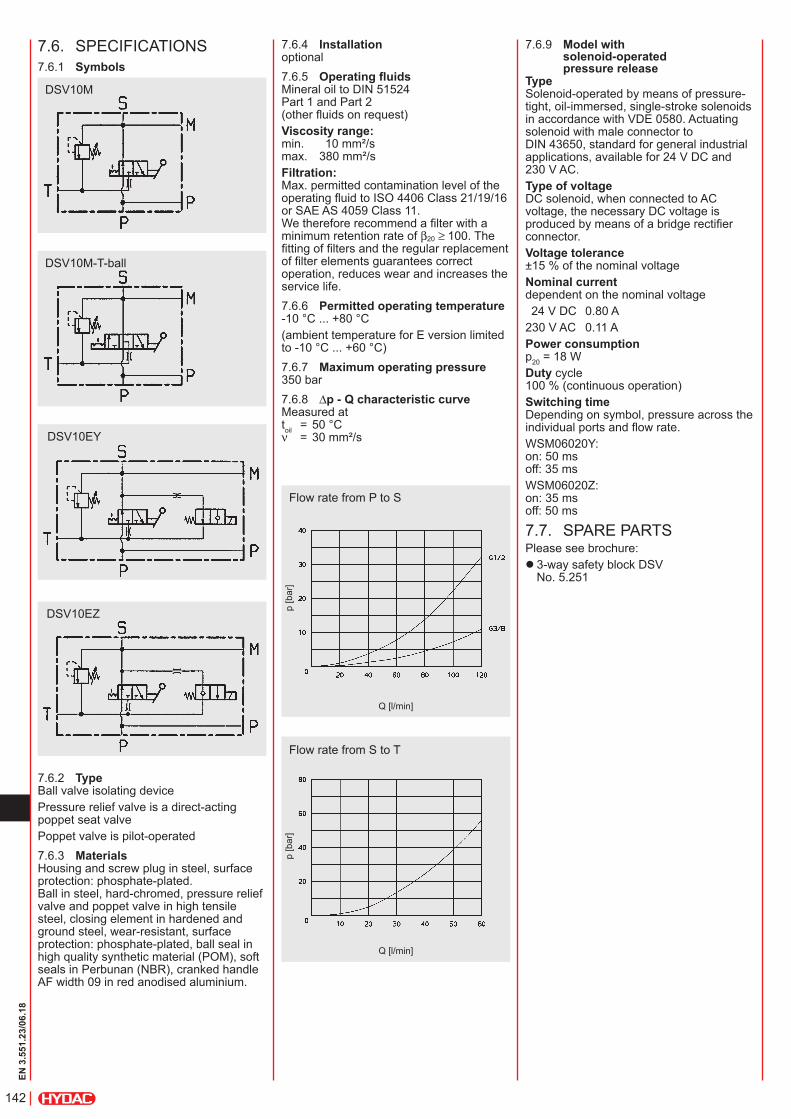
7.6. SPECIFICATIONS7.6.1 Symbols
7.6.2 TypeBall valve isolating devicePressure relief valve is a direct-acting poppet seat valvePoppet valve is pilot-operated7.6.3 MaterialsHousing and screw plug in steel, surface protection: phosphate-plated. Ball in steel, hard-chromed, pressure relief valve and poppet valve in high tensile steel, closing element in hardened and ground steel, wear-resistant, surface protection: phosphate-plated, ball seal in high quality synthetic material (POM), soft seals in Perbunan (NBR), cranked handle AF width 09 in red anodised aluminium.
DSV10M
DSV10M-T-ball
DSV10EY
DSV10EZ
7.6.4 Installationoptional7.6.5 Operating fluidsMineral oil to DIN 51524 Part 1 and Part 2 (other fluids on request)Viscosity range: min. 10 mm²/s max. 380 mm²/sFiltration: Max. permitted contamination level of the operating fluid to ISO 4406 Class 21/19/16 or SAE AS 4059 Class 11. We therefore recommend a filter with a minimum retention rate of β20 ≥ 100. The fitting of filters and the regular replacement of filter elements guarantees correct operation, reduces wear and increases the service life.7.6.6 Permitted operating temperature-10 °C ... +80 °C(ambient temperature for E version limited to -10 °C ... +60 °C)7.6.7 Maximum operating pressure350 bar7.6.8 ∆p - Q characteristic curveMeasured at toil = 50 °C ν = 30 mm²/s
Flow rate from P to S
Flow rate from S to T
p [b
ar]
Q [l/min]
p [b
ar]
Q [l/min]
7.6.9 Model with solenoid-operated pressure release
Type Solenoid-operated by means of pressure-tight, oil-immersed, single-stroke solenoids in accordance with VDE 0580. Actuating solenoid with male connector to DIN 43650, standard for general industrial applications, available for 24 V DC and 230 V AC.Type of voltage DC solenoid, when connected to AC voltage, the necessary DC voltage is produced by means of a bridge rectifier connector.Voltage tolerance ±15 % of the nominal voltageNominal current dependent on the nominal voltage 24 V DC 0.80 A230 V AC 0.11 APower consumption p20 = 18 WDuty cycle 100 % (continuous operation)Switching time Depending on symbol, pressure across the individual ports and flow rate.WSM06020Y: on: 50 ms off: 35 msWSM06020Z: on: 35 ms off: 50 ms
7.7. SPARE PARTSPlease see brochure:
z 3-way safety block DSV No. 5.251
143
EN 3
.551
.23/
06.1
8
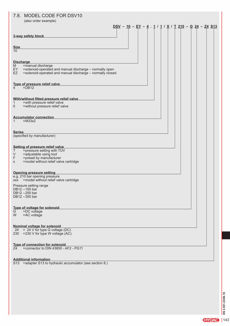
7.8. MODEL CODE FOR DSV10 (also order example)
DSV – 10 – EY – 4 . 1 / 1 / X / T 210 – G 24 – Z4 S13
3-way safety block
Size 10
Discharge M = manual discharge EY = solenoid-operated and manual discharge – normally open EZ = solenoid-operated and manual discharge – normally closed
Type of pressure relief valve 4 = DB12
With/without fitted pressure relief valve 1 = with pressure relief valve 0 = without pressure relief valve
Accumulator connection 1 = M33x2
Series (specified by manufacturer)
Setting of pressure relief valve T = pressure setting with TÜV V = adjustable using tool F = preset by manufacturer x = model without relief valve cartridge
Opening pressure setting e.g. 210 bar opening pressure xxx = model without relief valve cartridgePressure setting range DB12 – 150 bar DB12 – 250 bar DB12 – 350 bar
Type of voltage for solenoid G = DC voltage W = AC voltage
Nominal voltage for solenoid 24 = 24 V for type G voltage (DC) 230 = 230 V for type W voltage (AC)
Type of connection for solenoid Z4 = connector to DIN 43650 - AF2 - PG11
Additional information S13 = adapter S13 to hydraulic accumulator (see section 8.)
144
EN 3
.551
.23/
06.1
8
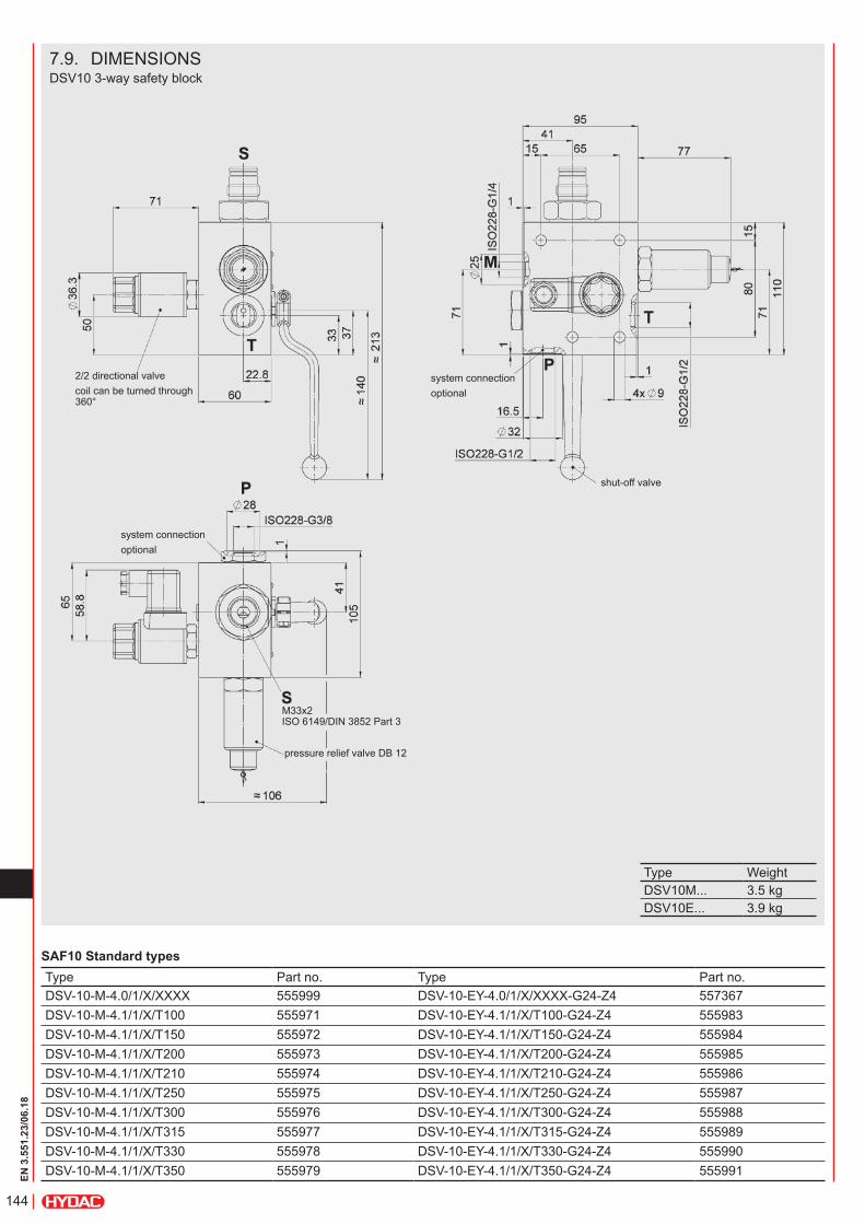
7.9. DIMENSIONSDSV10 3-way safety block
2/2 directional valvecoil can be turned through 360°
system connectionoptional
shut-off valve
system connectionoptional
M33x2 ISO 6149/DIN 3852 Part 3
pressure relief valve DB 12
Type WeightDSV10M... 3.5 kgDSV10E... 3.9 kg
SAF10 Standard typesType Part no. Type Part no.DSV-10-M-4.0/1/X/XXXX 555999 DSV-10-EY-4.0/1/X/XXXX-G24-Z4 557367DSV-10-M-4.1/1/X/T100 555971 DSV-10-EY-4.1/1/X/T100-G24-Z4 555983DSV-10-M-4.1/1/X/T150 555972 DSV-10-EY-4.1/1/X/T150-G24-Z4 555984DSV-10-M-4.1/1/X/T200 555973 DSV-10-EY-4.1/1/X/T200-G24-Z4 555985DSV-10-M-4.1/1/X/T210 555974 DSV-10-EY-4.1/1/X/T210-G24-Z4 555986DSV-10-M-4.1/1/X/T250 555975 DSV-10-EY-4.1/1/X/T250-G24-Z4 555987DSV-10-M-4.1/1/X/T300 555976 DSV-10-EY-4.1/1/X/T300-G24-Z4 555988DSV-10-M-4.1/1/X/T315 555977 DSV-10-EY-4.1/1/X/T315-G24-Z4 555989DSV-10-M-4.1/1/X/T330 555978 DSV-10-EY-4.1/1/X/T330-G24-Z4 555990DSV-10-M-4.1/1/X/T350 555979 DSV-10-EY-4.1/1/X/T350-G24-Z4 555991
145
EN 3
.551
.23/
06.1
8
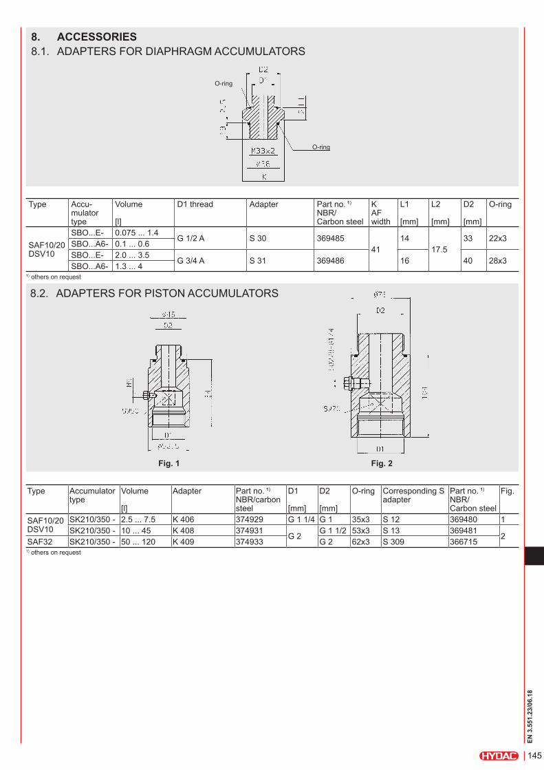
Type Accumulator type
Volume [l]
Adapter Part no. ¹) NBR/carbon steel
D1 [mm]
D2 [mm]
O-ring Corresponding S adapter
Part no. ¹) NBR/ Carbon steel
Fig.
SAF10/20 DSV10
SK210/350 - 2.5 ... 7.5 K 406 374929 G 1 1/4 G 1 35x3 S 12 369480 1SK210/350 - 10 ... 45 K 408 374931
G 2G 1 1/2 53x3 S 13 369481
2SAF32 SK210/350 - 50 ... 120 K 409 374933 G 2 62x3 S 309 366715
1) others on request
8.2. ADAPTERS FOR PISTON ACCUMULATORS
Fig. 1 Fig. 2
Type Accu-mulator type
Volume [l]
D1 thread Adapter Part no. ¹) NBR/ Carbon steel
K AF width
L1 [mm]
L2 [mm]
D2 [mm]
O-ring
SAF10/20 DSV10
SBO...E- 0.075 ... 1.4G 1/2 A S 30 369485
4114
17.533 22x3
SBO...A6- 0.1 ... 0.6SBO...E- 2.0 ... 3.5
G 3/4 A S 31 369486 16 40 28x3SBO...A6- 1.3 ... 4
¹) others on request
8. ACCESSORIES8.1. ADAPTERS FOR DIAPHRAGM ACCUMULATORS
O-ring
O-ring
146
EN 3
.551
.23/
06.1
8
Type Accu-mulator type
Volume [l]
Adapter Part no. ¹) NBR/ Carbon steel
Corresponding S adapter
Part no. ¹) NBR/ Carbon steel
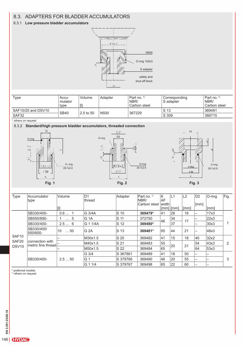
SAF10/20 and DSV10SB40 2.5 to 50 N500 367229
S 13 369481SAF32 S 309 366715
1) others on request
8.3. ADAPTERS FOR BLADDER ACCUMULATORS8.3.1 Low pressure bladder accumulators
N500
O-ring 102x3
S adapter
safety andshut-off block
8.3.2 Standard/high pressure bladder accumulators, threaded connection
O- ring29.7x2.8
O-ring
Fig. 1
O-ring29.7x2.8
O-ring
Fig. 2
O-ring29.7x2.8
Fig. 3
Type Accumulator type
Volume [l]
D1 thread
Adapter Part no. 1) NBR/ Carbon steel
K AF width [mm]
L1 [mm]
L2 [mm]
D2 [mm]
O-ring [mm]
Fig.
SAF10SAF20DSV10
SB330/400- 0.6 ... 1 G 3/4A S 10 369479* 41 28 16 – 17x3
1SB550/690- 1 ... 5 G 1A S 11 372750
4634
17– 22x3
SB330/400- 2.5 ... 6 G 1 1/4A S 12 369480* 37 – 30x3SB330/400/ 550/600- 10 ... 50 G 2A S 13 369481* 65 44 21 – 48x3
connection with metric fine thread
– M30x1.5 S 20 369482 41 15 18 40 32x22– M40x1.5 S 21 369483 55
20 2154 43x3
– M50x1.5 S 22 369484 65 64 53x3
SB330/400- 2.5 ... 50G 3/4 S 367861 369489 41 18 50 – –
3G 1 S 379766 369490 46 20 55 – –G 1 1/4 S 379767 369498 65 22 60 – –
* preferred models 1) others on request
147
EN 3
.551
.23/
06.1
8
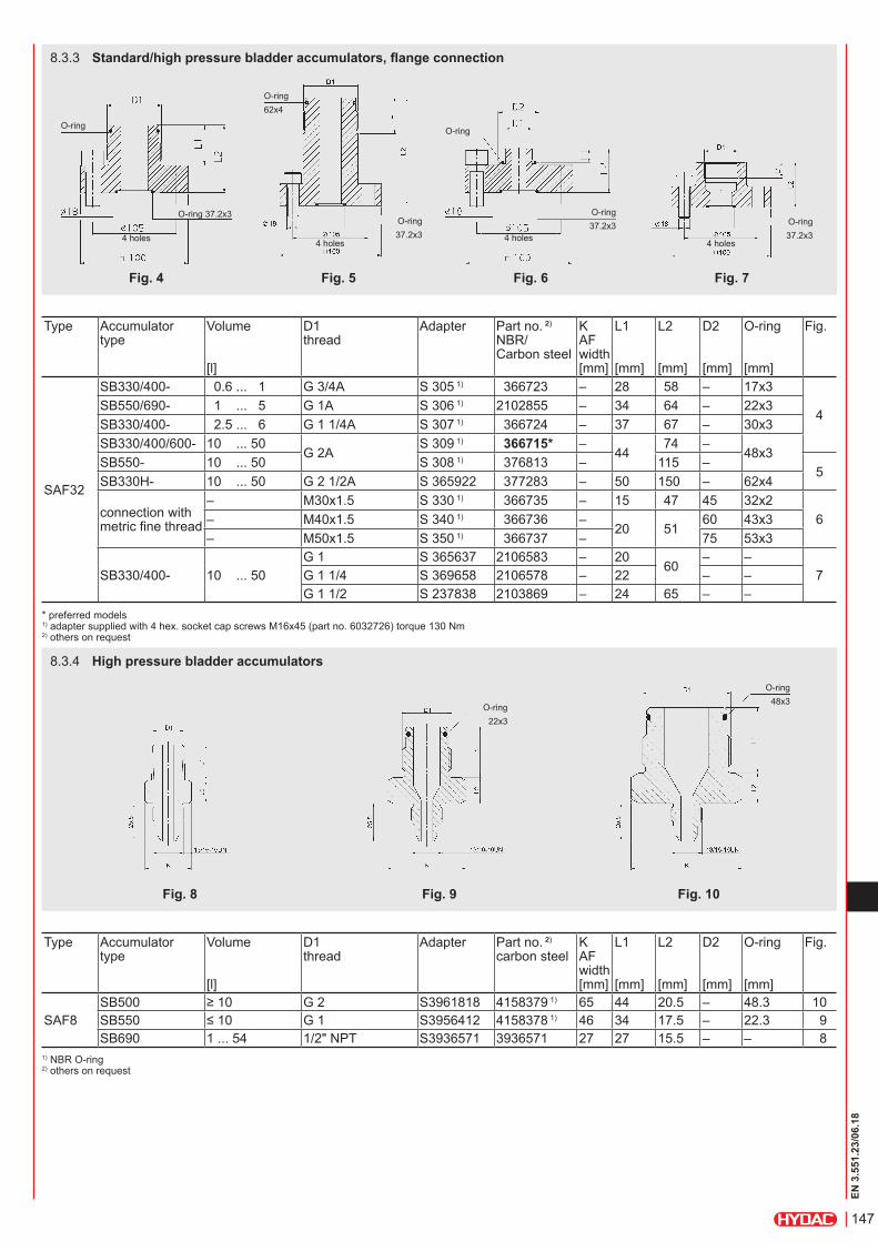
8.3.3 Standard/high pressure bladder accumulators, flange connection
O-ring
O-ring 37.2x3
4 holes
Fig. 4
O-ring62x4
4 holes
O-ring37.2x3
Fig. 5
O-ring
O-ring37.2x3
4 holes
Fig. 6
O-ring37.2x3
4 holes
Fig. 7
8.3.4 High pressure bladder accumulators
Fig. 8
O-ring22x3
Fig. 9
O-ring48x3
Fig. 10
Type Accumulator type
Volume [l]
D1 thread
Adapter Part no. ²) NBR/ Carbon steel
K AF width [mm]
L1 [mm]
L2 [mm]
D2 [mm]
O-ring [mm]
Fig.
SAF32
SB330/400- 0.6 ... 1 G 3/4A S 305 1) 366723 – 28 58 – 17x3
4SB550/690- 1 ... 5 G 1A S 306 1) 2102855 – 34 64 – 22x3SB330/400- 2.5 ... 6 G 1 1/4A S 307 1) 366724 – 37 67 – 30x3SB330/400/600- 10 ... 50
G 2AS 309 1) 366715* –
4474 –
48x3SB550- 10 ... 50 S 308 1) 376813 – 115 –
5SB330H- 10 ... 50 G 2 1/2A S 365922 377283 – 50 150 – 62x4
connection with metric fine thread
– M30x1.5 S 330 1) 366735 – 15 47 45 32x26– M40x1.5 S 340 1) 366736 –
20 5160 43x3
– M50x1.5 S 350 1) 366737 – 75 53x3
SB330/400- 10 ... 50G 1 S 365637 2106583 – 20
60– –
7G 1 1/4 S 369658 2106578 – 22 – –G 1 1/2 S 237838 2103869 – 24 65 – –
* preferred models 1) adapter supplied with 4 hex. socket cap screws M16x45 (part no. 6032726) torque 130 Nm 2) others on request
Type Accumulator type
Volume [l]
D1 thread
Adapter Part no. ²) carbon steel
K AF width [mm]
L1 [mm]
L2 [mm]
D2 [mm]
O-ring [mm]
Fig.
SAF8SB500 ≥ 10 G 2 S3961818 4158379 1) 65 44 20.5 – 48.3 10SB550 ≤ 10 G 1 S3956412 4158378 1) 46 34 17.5 – 22.3 9SB690 1 ... 54 1/2" NPT S3936571 3936571 27 27 15.5 – – 8
1) NBR O-ring 2) others on request
148
EN 3
.551
.23/
06.1
8
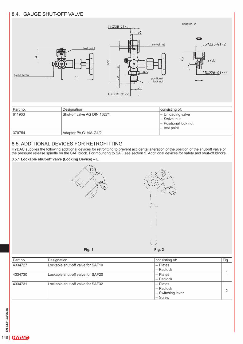
8.4. GAUGE SHUT-OFF VALVE
adapter PA
positional lock nut
bleed screw
test pointswivel nut
Part no. Designation consisting of:611903 Shut-off valve AG DIN 16271 – Unloading valve
– Swivel nut – Positional lock nut – test point
370754 Adaptor PA G1/4A-G1/2
8.5. ADDITIONAL DEVICES FOR RETROFITTINGHYDAC supplies the following additional devices for retrofitting to prevent accidental alteration of the position of the shut-off valve or the pressure release spindle on the SAF block. For mounting to SAF, see section 5. Additional devices for safety and shut-off blocks.8.5.1 Lockable shut-off valve (Locking Device) – L
Part no. Designation consisting of: Fig.4334727 Lockable shut-off valve for SAF10 – Plates
– Padlock1
4334730 Lockable shut-off valve for SAF20 – Plates – Padlock
4334731 Lockable shut-off valve for SAF32 – Plates – Padlock – Switching lever – Screw
2
Fig. 1 Fig. 2
149
EN 3
.551
.23/
06.1
8
9. NOTEThe information in this brochure relates to the operating conditions and applications described. For applications and operating conditions not described. please contact the relevant technical department. Subject to technical modifications.
HYDAC Technology GmbH Industriegebiet 66280 Sulzbach/Saar, Germany Tel.: +49 (0) 68 97 / 509 - 01 Fax: +49 (0) 68 97 / 509 - 464 Internet: www.hydac.com E-mail: [email protected]
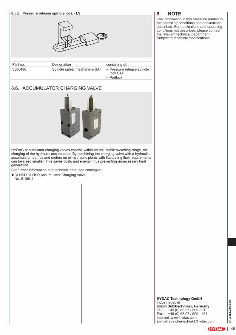
8.5.2 Pressure release spindle lock - LS
Part no. Designation consisting of:3580490 Spindle safety mechanism SAF – Pressure release spindle
lock SAF – Padlock
8.6. ACCUMULATOR CHARGING VALVE
HYDAC accumulator charging valves control, within an adjustable switching range, the charging of the hydraulic accumulator. By combining the charging valve with a hydraulic accumulator, pumps and motors on oil-hydraulic plants with fluctuating flow requirements can be sized smaller. This saves costs and energy, thus preventing unnecessary heat generation.For further information and technical data, see catalogue:
zDLHSD DLHSR Accumulator Charging Valve No. 5.190.1

150
EN 3
.551
.23/
06.1
8