Embed Size (px)
Citation preview
ANSI/PGMA G300-2018
© 2018 Portable Generator Manufacturers’ Association. All Rights Reserved.
SAFETY AND PERFORMANCE OF
PORTABLE GENERATORS
Sponsor:
AN
SI/
PG
MA
G3
00
-20
18
ANSI/PGMA G300-2018
© 2018 Portable Generator Manufacturers’ Association. All Rights Reserved.
ii
American National Standard implies a consensus of
those substantially concerned with its scope and
provisions. An American National Standard is
voluntary and intended as a guide to aid the
manufacturer, the consumer, and the general public.
The existence of a an American National Standard
does not in any respect preclude anyone, whether he
has approved the standard or not, from manufacturing,
marketing, purchasing or using products, processes, or
procedures not conforming to the standard. American
National Standards are subject to periodic review and
users are cautioned to obtain the latest editions.
CAUTION NOTICE:
This American National Standard may be revised or
withdrawn at any time. The procedures of the PGMA
require that action be taken to reaffirm, revise, or
withdraw this standard no later than five years from the
date of publication. Users of PGMA Standards may
receive current information on all standards by calling or
writing the Portable Generator Manufacturers'
Association.
Sponsored and published by:
PORTABLE GENERATOR MANUFACTURERS’ ASSOCIATION
1300 Sumner Avenue
Cleveland, OH 44115-2851 Phone: 216/241-7333
Fax: 216/241-0105
E-Mail: [email protected]
URL: www.pgmaonline.com
©2018 Portable Generator Manufacturers’ Association. All rights
reserved. No part of this standard may be reproduced or transmitted in any
form or by any means, electronic or mechanical, including but not limited
to photocopy, recording or any other information storage or retrieval
system known now or in the future, without the express written permission
of the Portable Generator Manufacturers’ Association.
Suggestions for improvement of this standard will be welcome.
They should be sent to the Portable Generator Manufacturers’ Association.
Printed in the United States of America
American National
Standard
ANSI/PGMA G300-2018
© 2018 Portable Generator Manufacturers’ Association. All Rights Reserved.
iii
CONTENTS
FOREWORD .................................................................................................................................. v
1 Scope ........................................................................................................................................ 1
2 Definitions ................................................................................................................................ 1
3 General Construction ................................................................................................................ 4
3.1 Guarding of Moving Parts ................................................................................................. 4
3.2 Live Parts ........................................................................................................................... 4
3.3 Surface Temperatures ........................................................................................................ 5
3.4 Sharp Edges ....................................................................................................................... 7
3.5 Corrosion Resistance ......................................................................................................... 7
3.6 Rain Test ............................................................................................................................ 7
3.7 Engine Shutoff Means ....................................................................................................... 7
3.8 Stability .............................................................................................................................. 8
3.9 Carbon Monoxide .............................................................................................................. 8
3.10 Emissions ..................................................................................................................... 12
4 Mechanical Construction ........................................................................................................ 12
4.1 Engines ............................................................................................................................ 12
4.2 Fuel Systems .................................................................................................................... 14
4.3 Mechanical Strength ........................................................................................................ 16
5 Electrical Construction ........................................................................................................... 17
5.1 Enclosures ........................................................................................................................ 17
5.2 Alternators ....................................................................................................................... 24
5.3 Batteries ........................................................................................................................... 26
5.4 Power Cords .................................................................................................................... 26
5.5 Grounding and Bonding .................................................................................................. 27
5.6 Spacings ........................................................................................................................... 29
5.7 Electrical Energy Storage Components ........................................................................... 31
5.8 Abnormal Operation ........................................................................................................ 31
6 Testing .................................................................................................................................... 31
6.1 General Conditions For Testing....................................................................................... 31
6.2 Safety Tests ...................................................................................................................... 32
6.2.1 Temperature Test ...................................................................................................... 32
6.2.2 Short Circuit Test ...................................................................................................... 34
6.2.3 Overload Test ............................................................................................................ 34
6.2.4 Overspeed Test .......................................................................................................... 35
6.2.5 Mechanical Stability Test .......................................................................................... 35
6.2.6 Drop Test .................................................................................................................. 35
6.2.7 Impact Test ................................................................................................................ 35
6.2.8 Lifting Test ................................................................................................................ 36
6.2.9 Dielectric Voltage Withstand Test ............................................................................ 36
6.2.10 Rain Test ................................................................................................................ 37
6.2.11 Carbon Monoxide Test .......................................................................................... 37
6.3 Performance Tests ........................................................................................................... 39
ANSI/PGMA G300-2018
© 2018 Portable Generator Manufacturers’ Association. All Rights Reserved.
iv
6.3.1 General ...................................................................................................................... 39
6.3.2 Output Power Rating ................................................................................................. 39
6.4 Manufacturing Tests ........................................................................................................ 42
7 Product and Packaging Labeling ............................................................................................ 43
7.1 Output Rating/Rating Plate .............................................................................................. 43
7.2 Hazard Labels and Safety Instructions ............................................................................ 44
7.3 Grounding ........................................................................................................................ 46
7.4 Packaging ......................................................................................................................... 49
8 Operators Manual, Operating Instructions and Warnings ...................................................... 49
9 Normative References ............................................................................................................ 51
Annex A (normative) Product markings ...................................................................................... 53
Figure 1 - IEC 61032 Test Probe 11 ............................................................................................... 4
Figure 2 - Test cones for hot parts accessibility .............................................................................. 6
Figure 3 - IEC 61032 Test Probe B ............................................................................................... 18
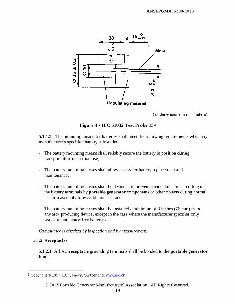
Figure 4 - IEC 61032 Test Probe 13 ............................................................................................. 19
Figure 5 - User instruction label ................................................................................................... 45
Figure 6 - Compliance logo .......................................................................................................... 46
Figure 7 - Symbol 5019 of IEC 60417 .......................................................................................... 48
Figure 8 - Symbol 5020 of IEC 60417 .......................................................................................... 48
Figure A.1 - On-product CO poisoning hazard label .................................................................... 55
Figure A.2 - Safety alert symbol ................................................................................................... 55
Figure A.3 - CO poisoning hazard label for package .................................................................... 55
Table 1- Minimum creepage and clearance distances ................................................................... 30
Table 2 - Surface Temperatures .................................................................................................... 33
Table 3 - Maximum acceptable temperature limits for insulation systems .................................. 33
Table 4 - Reference atmospheric conditions ................................................................................. 40
ANSI/PGMA G300-2018
© 2018 Portable Generator Manufacturers’ Association. All Rights Reserved.
v
SAFETY AND PERFORMANCE OF PORTABLE GENERATORS
FOREWORD NOTE This Foreword is included for information only and is not part of ANSI/PGMA G300-2018,
Safety and Performance of Portable Generators.
The following standard has been developed by the Technical Committee of the Portable
Generator Manufacturers’ Association (PGMA) as an assistance and guide to the
manufacturers, purchasers, and users of portable generators. It is intended to provide a
uniform method for evaluating the safety and performance of portable generators.
This standard is a revision to ANSI/PGMA G300-2015. The main differences between the
two standards are as follows:
New carbon monoxide requirements
New requirements added in accordance with NEC 2017
The ANSI Board of Standards Review granted approval of this document as an American
National Standard on April 20, 2018.
Effective Date
The effective date of this standard is March 31, 2020.
Any portable generator that is manufactured on or after the effective date , which claims to
comply with the PGMA G300 standard, shall comply with this version or a future version
this standard.
PGMA recognizes the need to periodically review and update this standard. Suggestions
for improvement should be forwarded to the Portable Generator Manufacturers’
Association, 1300 Sumner Avenue, Cleveland, Ohio, 44115-2851. All constructive
suggestions for expansion and revision of this standard are welcome.
The existence of a Portable Generator Manufacturers’ Association standard does not in
any respect preclude any member or non-member from manufacturing or selling products
not conforming to this standard nor is the PGMA responsible for its use.
In this standard, the following print types are used:
Requirements: in roman type
Test specification: in italic type
Notes: in smaller roman type
Words in bold in the text are defined in Clause 2.

ANSI/PGMA G300-2018
© 2018 Portable Generator Manufacturers’ Association. All Rights Reserved.
vi
PGMA thanks the International Electrotechnical Commission (IEC) for permission to
reproduce information from its International Standards IEC 61032 ed.2.0 (1997) and IEC
60417 Database (2014-12-02). All such extracts are copyright of IEC, Geneva,
Switzerland. All rights reserved. Further information on the IEC is available from
www.iec.ch. IEC has no responsibility for the placement and context in which the extracts
and contents are reproduced by PGMA, nor is IEC in any way responsible for the other
content or accuracy therein.
ANSI/PGMA G300-2018
© 2018 Portable Generator Manufacturers’ Association. All Rights Reserved.
1
SAFETY AND PERFORMANCE OF PORTABLE GENERATORS
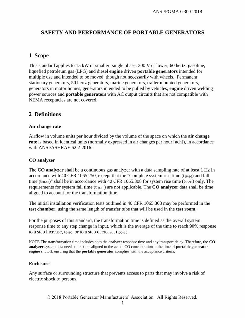
1 Scope
This standard applies to 15 kW or smaller; single phase; 300 V or lower; 60 hertz; gasoline,
liquefied petroleum gas (LPG) and diesel engine driven portable generators intended for
multiple use and intended to be moved, though not necessarily with wheels. Permanent
stationary generators, 50 hertz generators, marine generators, trailer mounted generators,
generators in motor homes, generators intended to be pulled by vehicles, engine driven welding
power sources and portable generators with AC output circuits that are not compatible with
NEMA receptacles are not covered.
2 Definitions
Air change rate
Airflow in volume units per hour divided by the volume of the space on which the air change
rate is based in identical units (normally expressed in air changes per hour [ach]), in accordance
with ANSI/ASHRAE 62.2-2016.
CO analyzer
The CO analyzer shall be a continuous gas analyzer with a data sampling rate of at least 1 Hz in
accordance with 40 CFR 1065.250, except that the "Complete system rise time (t10-90) and fall
time (t90-10)" shall be in accordance with 40 CFR 1065.308 for system rise time (t10-90) only. The
requirements for system fall time (t90-10) are not applicable. The CO analyzer data shall be time
aligned to account for the transformation time.
The initial installation verification tests outlined in 40 CFR 1065.308 may be performed in the
test chamber, using the same length of transfer tube that will be used in the test room.
For the purposes of this standard, the transformation time is defined as the overall system
response time to any step change in input, which is the average of the time to reach 90% response
to a step increase, t0−90, or to a step decrease, t100−10.
NOTE The transformation time includes both the analyzer response time and any transport delay. Therefore, the CO
analyzer system data needs to be time aligned to the actual CO concentration at the time of portable generator
engine shutoff, ensuring that the portable generator complies with the acceptance criteria.
Enclosure
Any surface or surrounding structure that prevents access to parts that may involve a risk of
electric shock to persons.
ANSI/PGMA G300-2018
© 2018 Portable Generator Manufacturers’ Association. All Rights Reserved.
2
Engine
An internal combustion device that converts fuel into mechanical power.
Guard
Any surface or surrounding structure that prevents access to parts that may involve a risk of
injury to persons due to mechanical or thermal hazards.
Live part
A conductive part intended to be energized in normal use that may pose a risk of electric shock
Load
An electrical demand expressed in watts; purely resistive.
Lubricants
The portable generator shall be tested with lubricants recommended by the manufacturer.
No load frequency
The measured frequency of the output voltage while no load is applied to the unit.
Normal operation
Operation at any load from no-load to rated wattage, within the rated ambient conditions
for the portable generator.
Ordinary tools
Ordinary tools are defined as the following: screwdrivers (slotted and Phillips head), pliers
(standard, needle nose and locking pliers), hammers, awls, wrenches, and tools supplied with the
portable generator. All other tools are not considered ordinary.
Portable generator
An engine-driven device that converts mechanical energy into electrical energy and is intended
to be movable to supply temporary electrical power.
Portable generator system for controlling CO exposure
Any system designed to shut off the portable generator engine within the acceptance
criteria.
ANSI/PGMA G300-2018
© 2018 Portable Generator Manufacturers’ Association. All Rights Reserved.
3
Receptacle
One or more electrical contact device(s) for the connection of an external attachment plug for the
purpose of supplying power.
Rated wattage
The output power rating of a portable generator as defined by the manufacturer.
Test equipment specifications
All test equipment shall meet the requirements of 6.3.2.3, unless otherwise specified.
Test chamber
The test chamber shall comply with UL2034 Section 41.2 for use in tests specified in 3.9.1 and
verification of CO analyzer requirements.
Test fuel(s)
The portable generator shall be tested with fuel(s) recommended by the manufacturer.
Test room
A fully enclosed space with a volume of 1280 to 1920 ft3 and constructed to control the air
change rate within 0 to 1 ach. The height of the test room shall be 8 - 12 ft. The length and
width of the test room shall be within 20% of each other. The generator shall be placed
approximately at the center of the test room. All CO measurements are to be taken at 1 -2 inches
(25.4 to 50.8 mm) above the approximate center of the portable generator's top surface.
Tool
Any object which is not part of the portable generator that is used in combination with a person’s
hand to operate a fastening device.
Voltage (V)
Potential difference measured between two points, either AC root mean square (RMS) or
DC.
ANSI/PGMA G300-2018
© 2018 Portable Generator Manufacturers’ Association. All Rights Reserved.
4
3 General Construction
3.1 Guarding of Moving Parts
3.1.1 Guards provided to protect against hazardous moving parts shall be inherently resistant
to corrosion or shall be suitably protected by appropriate means to resist corrosion in
accordance with 3.5.1.
Compliance is checked by inspection.
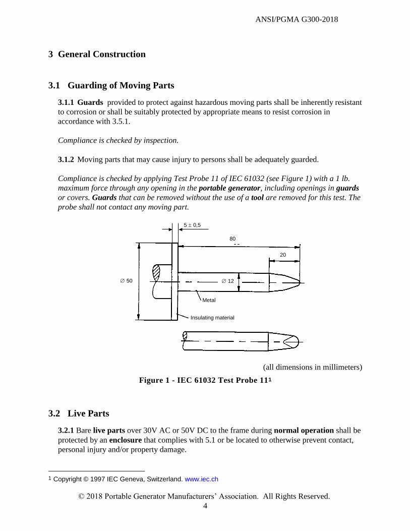
3.1.2 Moving parts that may cause injury to persons shall be adequately guarded.
Compliance is checked by applying Test Probe 11 of IEC 61032 (see Figure 1) with a 1 lb.
maximum force through any opening in the portable generator, including openings in guards
or covers. Guards that can be removed without the use of a tool are removed for this test. The
probe shall not contact any moving part.
Insulating material
Metal
5 0,5
80
20
12 50
(all dimensions in millimeters)
Figure 1 - IEC 61032 Test Probe 111
3.2 Live Parts
3.2.1 Bare live parts over 30V AC or 50V DC to the frame during normal operation shall be
protected by an enclosure that complies with 5.1 or be located to otherwise prevent contact,
personal injury and/or property damage.
1 Copyright © 1997 IEC Geneva, Switzerland. www.iec.ch
ANSI/PGMA G300-2018
© 2018 Portable Generator Manufacturers’ Association. All Rights Reserved.
5
Compliance is checked by the requirements of 5.1 or by inspection.
3.3 Surface Temperatures
3.3.1 Portable generators shall be designed to reduce the risk of burns or fire.
At the conclusion of the temperature test specified in 6.2.1, surface temperatures shall not
exceed the limits as specified in Table 2 or else the surface shall comply with 3.3.2.
3.3.2 Any surface with a maximum surface temperature that exceeds the limits specified in
Table 2 shall be either:
Labeled in accordance with 7.2; or
Guarded in order to pass the test of 3.3.2.1
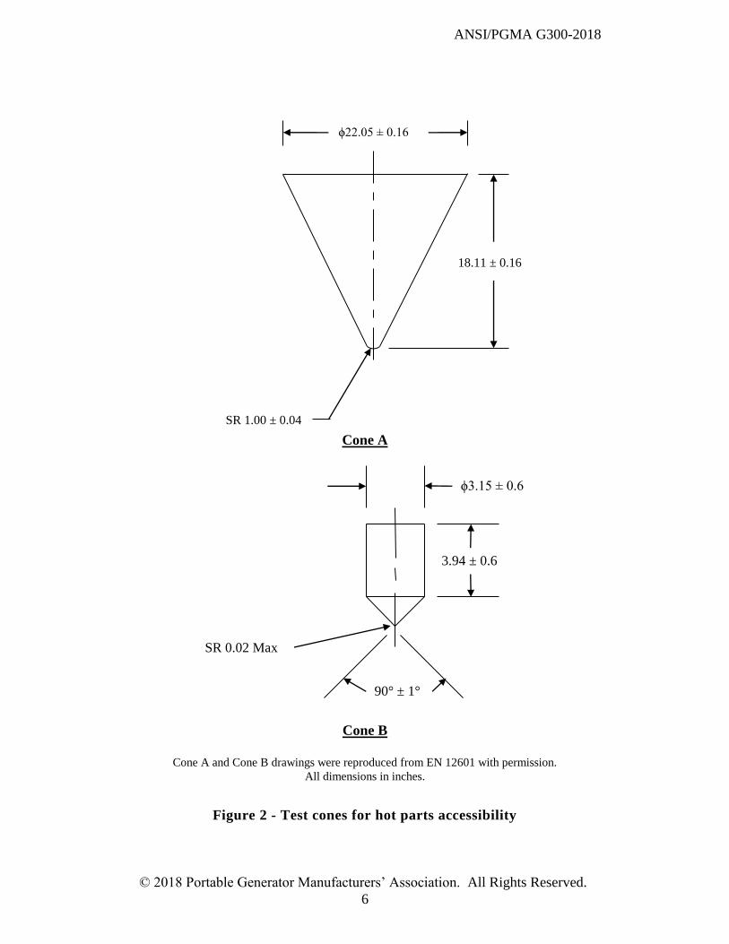
3.3.2.1 It is not necessary to test the accessibility of hot parts while they are hot. Allow
hot parts to cool before using the cone(s).
All hoods and guards shall be in their normal operating position during this test.
When the distance between the identified hot area and the nearest control is in excess of
100 mm (3.9 in), cone A as shown in Figure 2 shall be used. For distances less than or
equal to 100 mm (3.9 in) between the identified hot area and the nearest control, cone B as
shown in Figure 2 shall be used. For cone A, with the axis of the cone 90° to the horizontal
and with the nose or point of the cone in a downward direction, move the cone towards the
hot surface. The cone shall not be moved in an upward direction. When moving the cone,
determine if contact is made with the hot surface area(s) with the spherical tip. Cone B
(see Figure 2) shall be used with the axis of the cone in any direction and moved in any
direction.
The spherical tip of Cone A or spherical tip or conical surface of cone B shall not contact
any individual area of 10 cm² (1.55 in²) or more of the hot surface.
ANSI/PGMA G300-2018
© 2018 Portable Generator Manufacturers’ Association. All Rights Reserved.
6
Cone A
Cone B
Cone A and Cone B drawings were reproduced from EN 12601 with permission.
All dimensions in inches.
Figure 2 - Test cones for hot parts accessibility
ϕ3.15 ± 0.6
3.94 ± 0.6
90° ± 1°
SR 0.02 Max
ϕ22.05 ± 0.16
18.11 ± 0.16
SR 1.00 ± 0.04
ANSI/PGMA G300-2018
© 2018 Portable Generator Manufacturers’ Association. All Rights Reserved.
7
3.4 Sharp Edges
3.4.1 Parts that are likely to be touched during normal operation, maintenance or transport
shall be free from sharp edges, burrs, flashes and the like.
Compliance is checked by inspection or in case of doubt, the test described in UL 1439.
3.5 Corrosion Resistance
3.5.1 Ferrous metal parts used for the following purposes shall not create a hazard due to
corrosion or shall be suitably protected by plating, painting or equivalent means to resist
corrosion:
Electrically conductive parts;
Parts that are used as a bonding path;
Enclosures and guards for live parts and moving parts, including mounting hardware;
Exhaust system parts;
Fuel system parts including fuel lines, fittings and tanks; and
Mounting means for wet cell lead-acid batteries.
Compliance is checked by inspection.
3.5.2 Dissimilar metal or alloy joints or other dissimilar metal contact surfaces that promote
galvanic corrosion which could cause the portable generator to fail to comply with this
standard shall be avoided.
Compliance is checked by inspection.
3.6 Rain Test
The portable generator shall be capable of safe operation following the performance of a rain
test.
Compliance is checked by the test of 6.2.10.
3.7 Engine Shutoff Means
Portable generators shall be equipped with a means to readily shut off the engine. This may be
accomplished by electrical or mechanical means.
The engine shut off means specified above shall disable all engine start control circuits such that
the engine is incapable of starting.
Operation of the shut off means specified above shall initiate an engine shut down mechanism
that requires a mechanical reset.
ANSI/PGMA G300-2018
© 2018 Portable Generator Manufacturers’ Association. All Rights Reserved.
8
Compliance is checked by manual test.
3.8 Stability
Portable generators shall have adequate stability.
Compliance is checked by the test of 6.2.5.
3.9 Carbon Monoxide
All portable generators shall be designed to limit carbon monoxide (CO) exposure in the event
of misusing a portable generator.
Portable generator accessories to limit CO exposure shall meet the requirements of 6.2.11.
Compliance is checked by the test of 6.2.11.
3.9.1 Portable generator system for controlling CO exposure
The control system and sensing element of a portable generator system for controlling CO
exposure shall be constructed to operate in its working environment and throughout its design
life.
The control system and sensing element shall comply with the following tests specified in UL
2034. The tests a) through e) are made on separate samples. However, at the manufacturer’s
discretion, multiple tests may be performed on a sample.
a) Selectivity Test (42.1 through 42.6 only)
b) Dust Test (58.1 through 58.3 only), except that the test is performed with either
the control system and sensing element only, placed in its intended orientation;
or
the control system and sensing element mounted in its intended enclosure and
placed in its intended orientation.
c) Vibration Test (60.1, 60.3 and 60.4 only), except that for 60.3,the frequency of vibration
is to be varied from 10 to 75 cycles per second in increments of 5 cycles per second
until a resonant frequency is obtained. If no resonant frequency is obtained, vibrate at
75 cycles per second for 4 hours.
d) Corrosion Test (76.1 and 76.2 only), except that the test is performed with either
the control system and sensing element only, placed in its intended orientation;
or
the control system and sensing element mounted in its intended enclosure and
placed in its intended orientation
e) Variable Ambient Temperature and Humidity Test (75.1, 75.3 and 75.4 only).
ANSI/PGMA G300-2018
© 2018 Portable Generator Manufacturers’ Association. All Rights Reserved.
9
After each of the tests a) through e) above, the control system and sensing element shall pass
the following test:
The control system and sensing element is conditioned for 48 hours at
(23 ± 3) °C ((73.4 ± 5) °F);
(50 ± 20) percent relative humidity; and
(20.9 ± 0.2) percent oxygen concentration by volume.
Following the above conditioning, the control system and sensing element is placed in a test
chamber that incorporates a CO analyzer. Carbon monoxide is introduced in the test
chamber so that a uniform concentration of 810 - 850 ppm is achieved in the test chamber
within three to five minutes. The control system shall generate a signal to shut off the portable
generator engine before a carbon monoxide concentration exceeding 800 ppm is present in
the test chamber.
After the signal to shut off the portable generator engine is generated, a simulated portable
generator engine start signal is sent to the control system, while maintaining a uniform
concentration of 810 - 850 ppm in the test chamber. The control system shall generate a
signal to shut off the portable generator engine within 30 seconds of the introduction of the
simulated portable generator engine start signal.
Purge the test chamber with fresh air to remove all CO and clear any accumulated CO
control system history. Introduce carbon monoxide into the test chamber such that a uniform
concentration of 410 -430 ppm is achieved within three to five minutes. The control system
shall generate a signal to shut off the portable generator engine before the 10 minute rolling
average exceeds 400 ppm. The 10 minute rolling average is calculated by the average
measurement of the CO analyzer over the prior 10 minute period, with the initial 10 minute
time period starting at or before the introduction of carbon monoxide into the test chamber.
NOTE It is intended that the portable generator system for controlling CO exposure provides a shutoff
signal before the 10 minute rolling average CO concentration exceeds 400 ppm (not just when the measured
concentration continuously exceeds 400 ppm for 10 minutes). It is not intended that the portable generator
system for controlling CO exposure will reset the rolling average calculation if a concentration less than
400 ppm is measured. Furthermore, it is intended that the portable generator system for controlling CO
exposure provides a shutoff signal in accordance with the 800 ppm single value and the 400 ppm 10 minute
rolling average value, independent of the CO accumulation rate or profile. The rolling average is calculated
as shown below.
where
Mt is the rolling average at time t
Xt, Xt-1, etc. are measured values taken by the CO analyzer
ANSI/PGMA G300-2018
© 2018 Portable Generator Manufacturers’ Association. All Rights Reserved.
10
N is the total number of measured values Xt, Xt-1, etc.
The portable generator system for controlling CO exposure shall also meet the
requirements of 3.9.1.1 to 3.9.1.4.
3.9.1.1 Self-monitoring system
A portable generator system for controlling CO exposure shall contain a self
monitoring system to detect the correct operation of the carbon monoxide sensing element,
loss of power source for the portable generator system for controlling CO exposure and
end of life.
The self monitoring system shall shut off the portable generator engine upon fault
detection and end of life.
Compliance is checked by the following test.
With the engine operating, apply a fault of the carbon monoxide sensing element, loss of
power source for the portable generator system for controlling CO exposure
and end of life condition, one at a time. The engine shall shut off after each fault or end of
life is introduced.
3.9.1.2 Tamper Resistance
3.9.1.2.1 A portable generator system for controlling CO exposure shall be tamper
resistant.
The system is considered tamper resistant when all parts, including wiring, which affect
proper operation of the portable generator system for controlling CO exposure, meet
at least one of the following:
the part is permanently sealed;
the part is not normally accessible by hand or with ordinary tools; or
removal or disconnection of the part prevents the engine from running.
It is permissible for different parts of the portable generator system for
controlling CO exposure to meet the above requirement using any of the options
above, provided all of the different parts meet at least one of the options above.
Compliance is checked by inspection and by manual test.
3.9.1.2.2 Construction of the portable generator shall minimize the risk of intentional
blockage of the portable generator system for controlling CO exposure gas inlet.
Compliance is checked by inspection.
ANSI/PGMA G300-2018
© 2018 Portable Generator Manufacturers’ Association. All Rights Reserved.
11
3.9.1.2.3 Construction of the portable generator shall minimize the risk of incidental
damage to the portable generator system for controlling CO exposure.
Compliance is checked by inspection.
3.9.1.2.4 The portable generator system for controlling CO exposure shall not
incorporate any type of override function or feature.
Compliance is checked by inspection.
3.9.1.3 Notification
The portable generator system for controlling CO exposure shall include a prominent
and conspicuous notification in a readily visible location. The indicator shall contrast with
the background color and allow the indicator to be viewed by a user with normal vision
under expected visibility conditions and shall be located in a position not easily obscured
during use. The notification shall be dedicated to the portable generator system for
controlling CO exposure. Components of the notification shall have a design life greater
than the end of life of the portable generator system for controlling CO exposure.
Portable generators equipped with remote start capability via a removable control panel
shall have visual notifications on both the main portable generator unit, and on the
removable control panel. Both notifications shall comply with all notification requirements
on the portable generator unit contained in this standard. This requirement does not apply
to redundant remote controls.
Compliance is checked by inspection.
3.9.1.3.1 CO Shutoff Event Notification
The portable generator system for controlling CO exposure shall provide a
notification after a CO shutoff event. The notification shall be a red indication and may
be blinking, with a maximum period of 2 seconds.
The notification shall remain for a minimum of 5 minutes after a shutoff occurs unless
the portable generator engine is restarted. If the portable generator engine is
restarted, the notification shall not be present.
Compliance is checked by the test specified in 6.2.11.
3.9.1.3.2 System Fault Event Notification
The portable generator system for controlling CO exposure shall provide a non-red
indication if an end of life condition or a system electrically detectable fault is present,
ANSI/PGMA G300-2018
© 2018 Portable Generator Manufacturers’ Association. All Rights Reserved.
12
except for loss of the power source for the portable generator system for controlling CO
exposure. The notification may be blinking, with a maximum period of 2 seconds. The
notification shall remain for a minimum of 5 minutes after a fault is detected.
Compliance is checked by the test specified in 3.9.1.1.
3.9.1.4 Carbon Monoxide Sensor
A portable generator system for controlling CO exposure shall contain a carbon
monoxide sensing element bearing the UL Recognized Component Mark or an equivalent
Nationally Recognized Testing Laboratory (NRTL) component mark.
The carbon monoxide sensing element shall be suitable for use in a product that conforms
to ANSI/UL 2034.
Compliance is checked by inspection.
3.10 Emissions
All spark-ignited portable generator engines shall comply with the applicable requirements of
the U.S. Code of Federal Regulations, Title 40, Part 1054, Control of Emissions from New, Small
Nonroad Spark-Ignition Engines and Equipment.
Compliance is checked by the applicable tests of the U.S. Code of Federal Regulations, Title 40,
Part 1054.
4 Mechanical Construction
4.1 Engines
4.1.1 General
4.1.1.1 Start/Stop Safety
4.1.1.1.1 Manual Starting Safety
Engines shall be positioned in a manner that allows the recoil starter handle to be fully
extracted/retracted without user contact with harmful surfaces or edges.
Compliance is checked by inspection.
4.1.1.1.2 Remote Start Safety
When equipped, remote start systems that employ a remote control separate from the
portable generator shall be so designed as to prevent inadvertent starting by requiring a
ANSI/PGMA G300-2018
© 2018 Portable Generator Manufacturers’ Association. All Rights Reserved.
13
minimum of two separate actions for activation.
Remote start capability shall be disabled after a CO shutoff event until the portable
generator has been restarted non-remotely.
Compliance is checked by inspection.
4.1.1.1.3 Shut-Down Safety
Portable generators shall be equipped with a suitable means for unit shut-down that
meets all of the following requirements:
The shut-down mechanism shall require only one action;
The shut-down mechanism shall override all run commands;
A minimum of one shut-down mechanism shall be open for access at all times
and shall not be positioned in such a manner that requires the removal or
opening of any material (i.e. panel cover) that requires use of a tool; and
All shut-down mechanisms shall be labelled or marked with an indication of
their function and the required action to activate the function.
Compliance is checked by inspection.
4.1.1.2 Engine Overspeed Safety
Portable generators shall not create hazards to persons in the event of an engine
overspeed condition.
Compliance is checked by the test of 6.2.4.
4.1.1.3 Power Output
The means of connecting to the power output of a portable generator shall be suitably
designed to match the intended voltage and frequency and shall be appropriately
overcurrent protected.
Receptacles shall be powered by circuits of specified output (voltage and frequency)
and shall be limited to rated amperage via adequate overcurrent protection.
NOTE In the case of parallel operation of inverter units, additional overcurrent protection of
individual receptacles may be required.
Compliance is checked by inspection.
4.1.1.4 Synchronous portable generators
ANSI/PGMA G300-2018
© 2018 Portable Generator Manufacturers’ Association. All Rights Reserved.
14
Portable generators that use synchronous technology shall have the throttle controlled in
such a manner that the output frequency is maintained between 57 and 63 Hz during
normal operation. This requirement does not apply when a device reduces engine speed
under no-load conditions.
Compliance is checked by measurements.
4.1.2 Exhaust System
4.1.2.1 General requirements
Portable generators shall have a complete factory installed exhaust system, including any
required guarding to meet the requirements of 4.1.2.2 and 4.1.2.3.
Compliance is checked by inspection.
4.1.2.2 Exhaust system protection
Components of the exhaust system shall comply with 3.3 (Surface Temperatures)
regarding exposure to hot surfaces.
Appropriate guards or heat shields shall be provided to prevent contact with hot
exhaust parts during normal operation of the portable generator. Guards and
shields shall be constructed with adequate strength and shall be protected against
deterioration from corrosion in accordance with 3.5.1.
Compliance is checked by inspection and by the tests of 3.3.
4.1.2.3 A muffler spark arrester per USDA Forest Service Standard 5100-1d shall be
factory installed in the exhaust system or be made available, with installat ion
instructions, to the user.
Compliance is checked by inspection.
4.2 Fuel Systems
4.2.1 Fuel Systems – General
Fuel systems shall be so designed and constructed as to withstand the effects of normal and
expected use, without leakage.
Compliance is checked by the relevant tests of ANSI/OPEI B71.10 - 2013.
4.2.1.1 Fuel Fill Overflow – Portable Generator System for Controlling CO Exposure
ANSI/PGMA G300-2018
© 2018 Portable Generator Manufacturers’ Association. All Rights Reserved.
15
The portable generator shall be designed and constructed to prevent overflow of fuel
from contacting the CO sensor. This requirement only applies to gasoline and diesel fuels
used on a portable generator.
Compliance is checked by the test specified in 5.5 of ANSI/OPEI B71.10, except that test
fuel(s) shall be used. After the test, the portable generator shall pass the test of 6.2.11.
4.2.2 Liquefied Petroleum Gas (LPG)
4.2.2.1 General
A shut-off valve shall be provided on the manufacturer’s specified fuel container, or
between the fuel container and fuel system regulator.
Provision shall be made to compensate for expansion, contraction, jarring, and vibration.
This may be accomplished by flexible connections.
An automatic shutoff valve shall be provided in the fuel system at some point ahead of the
inlet of the gas-air mixer, designed to prevent flow of fuel to the mixer when the ignition is
off and the engine is not operating. Two-stage atmospheric type regulators (zero
governors) shall be considered adequate as an automatic shutoff valve.
Compliance is checked by inspection.
4.2.2.2 LP Cylinder
If the portable generator is provided with a LP cylinder, the LP cylinder shall be a
certified vapor withdrawal DOT vertical cylinder. The valve shall include a Type 1
ACME/OPD (Overflow Protection Device), in accordance with ANSI Z21.81.
A manual shutoff valve shall also be supplied with the cylinder.
Compliance is checked by inspection.
4.2.2.3 LP Cylinder Retention
This subclause only applies if a manufacturer provides a method for LP cylinder retention.
Provision shall be made to secure the LP cylinder while transporting the portable
generator and when the unit is operating within the manufacturer’s recommended
operating range.
Compliance is checked by inspection.
ANSI/PGMA G300-2018
© 2018 Portable Generator Manufacturers’ Association. All Rights Reserved.
16
4.2.2.4 LP Regulator
The first stage (high pressure) regulator shall be rated to withstand a minimum 250 psi
input pressure. Output pressure of the second stage regulator shall be rated to be within the
limits of the specific mixer used in the engine application.
Compliance is checked by inspection.
4.2.2.5 LP Flexible Hose, Couplings and Connectors
All components shall be rated to perform in the temperature range of -40° F to 130° F
(-40° C to 54.5° C).
Components shall be listed to UL569.
Hose shall be fabricated of materials that are resistant to the action of LP-Gas in liquid and
vapor phases, and oil. If wire braid is used for reinforcing the hose, it shall be of corrosion-
resistant material such as stainless steel.
Compliance is checked by inspection.
4.2.2.5.1 High Pressure Flexible Hose, Couplings and Connectors
Components shall be rated for working pressure of not less than 250 psig.
Compliance is checked by inspection.
4.2.2.5.2 Low Pressure Flexible Hose, Couplings and Connectors
Components shall be rated for working pressure of at least 1 psig.
Compliance is checked by inspection.
4.3 Mechanical Strength
Portable generators shall be constructed to withstand rough handling that may be expected
during transportation and use.
Compliance is checked by the tests of 6.2.6, 6.2.7 and 6.2.8.

ANSI/PGMA G300-2018
© 2018 Portable Generator Manufacturers’ Association. All Rights Reserved.
17
5 Electrical Construction
5.1 Enclosures
5.1.1 General requirements
5.1.1.1 Enclosures shall be mounted in a reliable manner and shall have sufficient
mechanical strength to withstand stresses that may occur during normal use and reasonably
foreseeable misuse.
Compliance is checked by inspection, by the requirements of 5.1.1.2 and 5.1.1.3 and by
the tests of 6.2.6 and 6.2.7.
5.1.1.2 Enclosures shall be constructed of material inherently resistant to corrosion or
shall be suitably protected by appropriate means to resist corrosion in accordance with
3.5.1.
Compliance is checked by inspection.
5.1.1.3 Polymeric enclosures shall be evaluated to the requirements for "all other
portable equipment" in Table 4.1 and Table 12.1 of UL 746C, or equivalent.
The manufacturer may substitute the requirements of subclause 12.4.6 of CSA C22.2 No.
100-14 for both the minimum flammability requirement of Table 4.1 and the glow-wire
temperature requirement of Table 12.1 in UL 746C.
Compliance is checked by inspection and by the relevant tests of UL 746C or CSA C22.2
No. 100-14, as applicable.
5.1.1.4 Openings in enclosures shall not allow user access to any live part, bare
conductor or magnet wire with a voltage that may exceed 30 VAC or 50 VDC during
normal use.
Live parts, bare conductors and magnet wire are considered to be accessible to users if the
following criteria are met:
- All guards, covers, shields and the like that are removable without the use of a tool
shall be removed;
- The live part, bare conductor or magnet wire can be contacted using IEC 61032 Test
Probe B (see Figure 3); or
- The live part, bare conductor or magnet wire can be contacted using IEC 61032 Test
ANSI/PGMA G300-2018
© 2018 Portable Generator Manufacturers’ Association. All Rights Reserved.
18
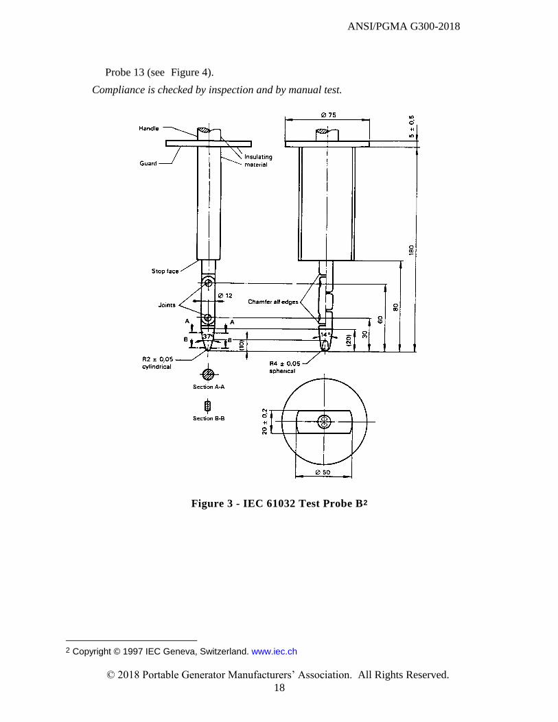
Probe 13 (see Figure 4).
Compliance is checked by inspection and by manual test.
Figure 3 - IEC 61032 Test Probe B2
2 Copyright © 1997 IEC Geneva, Switzerland. www.iec.ch
ANSI/PGMA G300-2018
© 2018 Portable Generator Manufacturers’ Association. All Rights Reserved.
19
(all dimensions in millimeters)
Figure 4 - IEC 61032 Test Probe 133
5.1.1.5 The mounting means for batteries shall meet the following requirements when any
manufacturer's specified battery is installed:
- The battery mounting means shall reliably secure the battery in position during
transportation or normal use;
- The battery mounting means shall allow access for battery replacement and
maintenance;
- The battery mounting means shall be designed to prevent accidental short-circuiting of
the battery terminals by portable generator components or other objects during normal
use or reasonably foreseeable misuse: and
- The battery mounting means shall be installed a minimum of 3 inches (76 mm) from
any arc- producing device, except in the case where the manufacturer specifies only
sealed maintenance-free batteries.
Compliance is checked by inspection and by measurement.
5.1.2 Receptacles
5.1.2.1 All AC receptacle grounding terminals shall be bonded to the portable generator
frame.
3 Copyright © 1997 IEC Geneva, Switzerland. www.iec.ch
ANSI/PGMA G300-2018
© 2018 Portable Generator Manufacturers’ Association. All Rights Reserved.
20
Compliance is checked by inspection and by measurements.
5.1.2.2 Receptacle faces shall:
be flush with or project from non-conductive mounting surfaces, or
project a minimum of 0.4 mm (0.015 in.) from conductive mounting surfaces.
Compliance is checked by measurements.
5.1.2.3 Receptacles shall comply with ANSI/NEMA WD6, unless they are used solely
for the purpose of connecting portable generators in parallel.
Compliance is checked by inspection.
5.1.2.4 Receptacles shall have listed ground-fault circuit-interrupter (GFCI) protection
integral to the portable generator or receptacle as specified in 5.1.2.4.1 and 5.1.2.4.2, as
applicable.
Exception: Portable generators intended for use in temporary wiring installations
that supply temporary power to equipment used by personnel during construction,
remodeling, maintenance, repair, or demolition of buildings, structures, equipment,
or similar activities shall:
be provided with ground-fault circuit-interrupter protection for personnel on all
125-volt and 125/250-volt, single-phase, 15-, 20-, and 30-ampere receptacle
outlets; and
when used in a damp or wet location, comply with 406.9(A) and (B) of the
National Electrical Code.
Compliance is checked by inspection.
5.1.2.4.1 For portable generators where the neutral is floating and that incorporate
both 125-volt and 125/250-volt receptacles, any 125-volt, 15- or 20-ampere receptacle
shall have listed GFCI protection integral to the portable generator or receptacle.
Exception: GFCI protection shall not be required where any 125-volt receptacle is
interlocked such that it is not available for use when any 125/250-volt receptacle is in
use.
5.1.2.4.2 For portable generators where the neutral is bonded to the frame, any
125-volt, 15- or 20-ampere receptacle shall be provided with GFCI protection.
5.1.2.5 Ground Fault Circuit Interrupters, if provided, shall comply with UL 943.
Compliance is checked by inspection.
ANSI/PGMA G300-2018
© 2018 Portable Generator Manufacturers’ Association. All Rights Reserved.
21
5.1.3 Wiring
The following subclause applies to wiring as contained within enclosures as well as any
wiring present on a portable generator. For alternator wiring, subclause 5.2.2.2 takes
precedence should any variation in requirements exist between the two subclauses.
Compliance is checked by the relevant portions of 5.1.3.1 and 5.2.2.2.
5.1.3.1 Conductor Size
Wiring shall be appropriately rated for a particular application with respect to temperature,
voltage, current and environmental fluids to which it may be exposed. The conductor size
shall be suitable for the maximum current required in the system and subsystems of the
portable generator. The wiring insulation shall be suitable for the current, temperatures
and environment to which it is exposed. Both shall satisfy NFPA 70 Article 310.
Alternately, wiring conductor size can be reduced in gauge size when temperature test
results show that the wire temperature and device terminal rated temperatures are within
the manufacturer’s ratings. Temperature test to be performed as in 6.2.1.
Compliance is checked by inspection.
5.1.3.2 Wiring Connections
5.1.3.2.1 Terminals
Terminals shall be suitable for the wire type, wire material, wire diameter and the
anticipated current. Where insulated terminals are used, these shall also be suitable for
the anticipated temperature and voltage.
Terminals made of ferrous material shall be plated or otherwise protected against
corrosion.
Compliance is checked by inspection.
5.1.3.2.2 Solder Connections
Terminal connections made using solder shall be mechanically secured prior to
soldering, except as provided in 5.1.3.2.2.1 below. Wrapping the conductor bundle with
wire and/or twisting the conductors together are considered adequate.
Compliance is checked by inspection.
5.1.3.2.2.1 Where failure of the solder joint cannot result in inadvertent contact or
shorting additional mechanical securing before soldering is not required.
ANSI/PGMA G300-2018
© 2018 Portable Generator Manufacturers’ Association. All Rights Reserved.
22
Note: Solder connections on printed wiring boards are covered by 5.1.4.
5.1.3.2.3 Terminal Connections
Terminals shall be prevented from turning, if such turning could result in damaged
wiring or unintended electrical contact. Friction between the terminal and a fixing screw
is not considered to be sufficient.
Open ended spade terminals shall be secured against inadvertent disconnection by
means of upturned ends or other deliberate securing method.
Stranded wire connections must include means to prevent loose strands from
inadvertently contacting conductive parts other than those intended. Crimped terminals,
solder tinning or other similar constructions may be used but wrapping of bare stranded
wire around a terminal screw is not allowed.
Compliance is checked by inspection.
5.1.4 Printed wiring boards
Printed wiring boards used in portable generators shall conform to IPC-2221B or UL 796.
Compliance is checked by inspection.
5.1.5 Overcurrent protection of portable generators
5.1.5.1 Protection of generator output AC circuits shall be provided in accordance with
subclause 5.1.5.2.
5.1.5.2 Readily accessible, having a rating equal to or less than the rating of the
receptacle, replaceable or manual reset type branch circuit protection or supplemental
protection may be used in the AC output circuits of portable generators provided that the
supplemental protector complies with the following:
it is suitable for use in industrial equipment;
it has an “overload must trip” classification TC0, TC1, or TC3;
it has a “suitable for further use” classification of U3 or U1a or has a classification of
C1a if provided with the required line side fuse or molded case circuit breaker;
its short-circuit rating is equal to or greater than the available current from the portable
generator output at rated voltage;
it has an overload rating classification of OL1; and
the 250 V single-phase output circuits are protected by multi-pole protectors.
ANSI/PGMA G300-2018
© 2018 Portable Generator Manufacturers’ Association. All Rights Reserved.
23
Exception: The overcurrent function may be provided within a solid-state circuit per
5.1.5.5.
Compliance is checked by inspection.
NOTE The following definitions are provided for information:
Short-circuit current rating (SC)
The test conditions and any calibration following the short-circuit test as defined below:
C - a short circuit test was conducted with series overcurrent protection
U – a short-circuit test was conducted without series overcurrent protection
1a - the supplementary protector was permanently open after the short -circuit test. A dielectric strength test
and a voltage withstand test were conducted.
3 - the protector has proven to be suitable for further use after the short-circuit test; recalibration, dielectric
strength and voltage withstand tests were performed after the short-circuit testing.
Tripping current (TC)
Tripping current is coded as a percentage of the ampere rating. Codes for UL & CSA products:
TC0 - tripping current is less than 125% of ampere rating
TC1 - tripping current is between 125 and 135% of ampere rating
TC3 - tripping current is standardized at 135% and at 200% of ampere rating
Overload rating (OL)
Designates whether the protector or family of protectors has been tested for general use or
motor-starting applications:
OL1 - tested at 6 times sac rating or 10 times DC rating for motor starting application.
5.1.5.3 Low voltage accessory output circuits, if provided, shall be appropriately protected
from electrical overload and short circuits.
Compliance is checked by the following test:
With the engine at the highest speed setting, apply a load as specified below for 5 minutes
each while monitoring the output voltage.
No-load (Circuit must operate properly during this portion of the test and no
overcurrent device may open)
50% of rated load (Circuit must operate properly during this portion of the test
and no overcurrent device may open)
100% of rated load (Circuit must operate properly during this portion of the test
and no overcurrent device may open)
130% of rated load (Circuit does not need to operate properly during this test and
overcurrent device(s) may open)
Short circuit (Circuit does not need to operate properly during this test and
overcurrent device(s) may open)
During the test, no damage to the portable generator shall occur and the output
voltage of the low voltage accessory output circuits shall not exceed the values
specified in 3.2.1.
ANSI/PGMA G300-2018
© 2018 Portable Generator Manufacturers’ Association. All Rights Reserved.
24
5.1.5.4 Low voltage accessory output circuits that are provided with a direct current
output intended to charge a non-integral battery shall be appropriately protected from
reverse polarity connection of the non-integral battery.
Compliance is checked by the following test:
Connect an appropriately rated fully charged battery to the battery charging output
incorrectly (reverse polarity) and run the portable generator at its highest speed setting for
5 minutes. During the test, there shall be no resulting hazardous condition, including flame
or molten metal. Opening of fuses during this test is acceptable. After the test, the unit
shall pass the dielectric voltage withstand test of 6.2.9.
5.1.5.5 Solid state overcurrent function (SSOF)
An AC output portable generator provided with a solid-state overcurrent function
shall:
Be capable of carrying rated circuit current without tripping;
Trip due to an overcurrent condition; and
Be capable of withstanding short circuits.
Compliance is checked by the following tests:
a) Connect the output to an adjustable resistive load bank.
b) A receptacle being protected by an SSOF shall carry the rated circuit current
for at least 5 min and must trip at no more than 135% of the receptacle’s
rated current.
c) A short circuit test is conducted five times as specified in 6.2.2. The maximum
short circuit current measured during the five tests shall be no more than the
short circuit current capability of the SSOF.
d) After the tests of 5.1.5.5 b) and 5.1.5.5 c) are completed, the SSOF shall
withstand the dielectric voltage withstand test of 6.2.9.
e) After the dielectric voltage withstand test of 5.1.5.5 d), the test of 5.1.5.5 c) is
repeated.
5.2 Alternators
5.2.1 Magnet Wire
Magnet wire shall be evaluated per ANSI/NEMA MW 1000. The maximum allowable magnet
wire temperatures during operation are given in Table 3.

ANSI/PGMA G300-2018
© 2018 Portable Generator Manufacturers’ Association. All Rights Reserved.
25
Compliance is checked by the temperature test of 6.2.1.
5.2.2 Construction
5.2.2.1 Portable generator output leads shall be evaluated based on the ampacity of the
wire and terminals, the size and mechanical strength of the wire, and the protection
required to prevent damage.
Leads not securely held in place shall be insulated with appropriate heat resistant insulated
tubing or other suitable means.
Compliance is checked by inspection.
5.2.2.2 Wiring
Standard appliance and building wire, such as those specified in NFPA 70 Article 310
(Conductors for General Wiring), shall be suitable for use.
Wiring shall not be liable to damage due to stress, vibration or rubbing on sharp objects
such as the end of a screw, the edge of a metal object, or other parts that could damage the
wire conductor or insulation.
Wiring shall be routed to avoid hot surfaces such as muffler exhaust system parts, hot
engine parts and moving parts.
Wiring shall not contact moving parts and shall be held securely in place.
Wiring that passes through a hole in a sheet-metal wall shall have smooth rounded surfaces
or bushings to prevent damage to insulated wires.
Compliance is checked by inspection.
5.2.2.3 Insulation on conductors used as leads shall be rated and evaluated to perform in
the intended application regarding voltage, ampacity and exposure to outside influences
like sunlight, oil, fuel or grease and other conditions that the wire and insulation may be
subjected.
Insulation on conductors shall be rated for the highest temperature to which it will be
subjected during use.
Compliance is checked by inspection.
5.2.2.4 Uninsulated terminals shall be securely held to supporting surfaces to prevent
turning or moving that would result in spacings below the values specified in 5.6.
ANSI/PGMA G300-2018
© 2018 Portable Generator Manufacturers’ Association. All Rights Reserved.
26
Compliance is checked by manual test and by measurement.
5.3 Batteries
5.3.1 Batteries supplied as part of the portable generator shall be securely held in place to
prevent damage from shifting due to tilting, dropping and vibration.
Compliance is checked by inspection.
5.3.2 Battery mechanical tie downs, if made from a conductive material such as a metal
strap or bolt, shall be so designed to avoid shorting to the battery posts and terminals.
The operating environment of the battery shall comply with its marked temperature ratings
and limits.
Compliance is checked by inspection and by measurement.
5.3.3 Battery terminal parts and leads shall be designed for the application and continuous
output current and cranking level that it will see during operation.
Compliance is checked by inspection.
5.3.4 Battery leads shall be positioned to avoid cracking, cutting or rubbing on sharp
surfaces.
Bushings, grommets, rounded edges or the like shall be used for routing battery leads
through sheet metal parts.
Compliance is checked by inspection.
5.3.5 The interior of a metal compartment housing a wet cell lead-acid battery shall be
protected against corrosion in accordance with 3.5.1.
Compliance is checked by inspection.
5.3.6 The mounting means for lead-acid batteries shall be provided with a means of
ventilation to prevent the collection of flammable gasses.
Compliance is checked by inspection.
5.4 Power Cords
5.4.1 If supplied with the portable generator, cords and associated fittings shall comply with
ANSI/PGMA G300-2018
© 2018 Portable Generator Manufacturers’ Association. All Rights Reserved.
27
the latest edition NFPA 70, Article 400 (Flexible Cords and Cables) and be rated for outdoor
use.
Compliance is checked by inspection.
5.4.2 Permanently attached wires or cords shall comply with the requirements of subclause
5.2.2.1.
Compliance is checked by inspection.
5.5 Grounding and Bonding
5.5.1 A portable generator shall be provided with a field grounding electrode conductor
location. The field grounding means shall be such that the factory bond between the field
grounding electrode conductor location and the portable generator frame is maintained at all
times.
Compliance is checked by inspection.
5.5.2 The field grounding means shall be able to accept an 8 AWG grounding electrode
conductor using a suitable connection means.
Compliance is checked by inspection.
5.5.3 All output receptacle ground terminals shall be bonded to the portable generator
frame.
Compliance is checked by inspection and by the test specified in subclause 5.5.7.
5.5.4 An output conductor of the portable generator alternator that is bonded to the portable
generator frame with a system bonding jumper shall meet the following requirements:
For a two wire output, the portable generator alternator conductor that is bonded to the
portable generator frame shall also be bonded to the neutral terminals of the output
receptacles;
For a three wire output, the portable generator alternator neutral conductor shall be
bonded to the portable generator frame as well as the neutral terminals of the output
receptacles.
Compliance is checked by inspection.
5.5.5 If a system bonding jumper described in subclause 5.5.4 is used, then it shall be sized
such that its ampacity is not less than the ampacity of the largest circuit conductor used in the
portable generator.
Compliance is checked by inspection.
5.5.6 For the case where no output conductors of the portable generator alternator is bonded
to the portable generator frame in subclause 5.5.4, the following requirements are
applicable:
ANSI/PGMA G300-2018
© 2018 Portable Generator Manufacturers’ Association. All Rights Reserved.
28
For a two wire output, the same portable generator alternator output conductor shall be
bonded to the neutral terminals of the output receptacles.
For a three wire output, the portable generator alternator neutral conductor shall be
bonded to the neutral terminals of the output receptacles.
5.5.7 All non-current-carrying metal parts that are accessible to users and are likely to become
energized due to an electrical fault shall be bonded to the portable generator frame. The
impedance between the field grounding means and any part required to be bonded shall be less
than 0.1 ohm.
Non-current-carrying metal parts are considered to be accessible to users if the following
criteria are met after all guards, covers, shields and the like that are removable without the
use of a tool are removed:
The part can be contacted using IEC 61032 Test Probe B; or
The part can be contacted using IEC 61032 Test Probe 13.
Non-current carrying metal parts are not considered likely to be energized due to an electrical
fault if the following criteria are met:
The part is insulated from electrical components and wiring by an insulating barrier of
vulcanized fiber, varnished cloth, phenolic composition, or other moisture-resistant
insulating material not less than 1/32 in (0.8 mm) thick ;
A moisture-resistant insulating material that has a suitable insulation rating is used to
insulate the non-current carrying metal parts from live parts ; or
The part is completely isolated from electrical components and wiring by other bonded
metal parts; or
The part is reliably and permanently separated from wiring or electrical components by
at least 0.25 inches.
Compliance is checked by inspection and by the following test:
Pass a minimum current of 25 amperes at 60 Hz nominal with an open circuit voltage less
than or equal to 6 volts between the field grounding means and any part required to be
bonded. The measured impedance is calculated by dividing the measured voltage drop by the
measured current. The measured impedance shall be less than 0.1 ohm.
5.5.8 The material used for bonding conductors shall be one of the following:
copper;
copper alloy;
another suitable conductive and corrosion-resistant material.
Compliance is checked by inspection.
5.5.9 Bonding conductors shall be one of the following types:
a wire with or without insulation;
ANSI/PGMA G300-2018
© 2018 Portable Generator Manufacturers’ Association. All Rights Reserved.
29
a bus bar; or
a strap.
Compliance is checked by inspection.
5.5.10 Bonding conductors shall have an ampacity not less than the largest circuit conductor
used in the portable generator.
Compliance is checked by inspection.
5.5.11 Bonding conductors shall be protected from foreseeable mechanical damage and
shall be suitable for the environment in which they are used, including:
voltage rating;
temperature rating; and
shock/vibration.
Compliance is checked by inspection.
5.5.12 The electrical connection for bonding conductors shall be accomplished by one of the
following methods:
Welding or soldering, using a material with a melting point above 850° F; or
a fastener, such as a bolt, screw or nut, that reliably penetrates any non-conductive
coating. If a fastener thread is used for the electrical connection, then at least two full
threads of the fastener must be utilized for the connection.
A bonding electrical connection shall not be secured by a fastener which may need to be
removed during operation or maintenance.
Compliance is checked by inspection.
5.5.13 Bonding conductors with insulation shall be marked as follows:
- the insulation color shall be green or green with one or more yellow stripes; or
- with symbol no. 5019 of IEC Publication 417 at each conductor end, except in the case
described in subclause 5.6.4 where this symbol is the only means used to identify the field
grounding means. In this case, the symbol no. 5019 of IEC Publication 417 with the circle
omitted may be used.
Compliance is checked by inspection.
5.6 Spacings
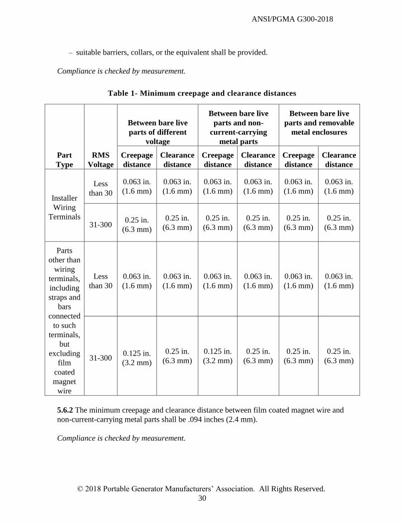
5.6.1 The minimum creepage and clearance distances between uninsulated live parts of
opposite polarity and between uninsulated live parts and non-current-carrying metal parts
shall be as shown in Table 1.
Exception: For brush holders and slip rings in portable generators, spacings shall be:
increased at least 50% of the relevant value in Table 1; or
ANSI/PGMA G300-2018
© 2018 Portable Generator Manufacturers’ Association. All Rights Reserved.
30
suitable barriers, collars, or the equivalent shall be provided.
Compliance is checked by measurement.
Table 1- Minimum creepage and clearance distances
Part
Type
RMS
Voltage
Between bare live
parts of different
voltage
Between bare live
parts and non-
current-carrying
metal parts
Between bare live
parts and removable
metal enclosures
Creepage
distance
Clearance
distance
Creepage
distance
Clearance
distance
Creepage
distance
Clearance
distance
Installer
Wiring
Terminals
Less
than 30
0.063 in.
(1.6 mm)
0.063 in.
(1.6 mm)
0.063 in.
(1.6 mm)
0.063 in.
(1.6 mm)
0.063 in.
(1.6 mm)
0.063 in.
(1.6 mm)
31-300 0.25 in.
(6.3 mm)
0.25 in.
(6.3 mm)
0.25 in.
(6.3 mm)
0.25 in.
(6.3 mm)
0.25 in.
(6.3 mm)
0.25 in.
(6.3 mm)
Parts
other than
wiring
terminals,
including
straps and
bars
connected
to such
terminals,
but
excluding
film
coated
magnet
wire
Less
than 30
0.063 in.
(1.6 mm)
0.063 in.
(1.6 mm)
0.063 in.
(1.6 mm)
0.063 in.
(1.6 mm)
0.063 in.
(1.6 mm)
0.063 in.
(1.6 mm)
31-300 0.125 in.
(3.2 mm)
0.25 in.
(6.3 mm)
0.125 in.
(3.2 mm)
0.25 in.
(6.3 mm)
0.25 in.
(6.3 mm)
0.25 in.
(6.3 mm)
5.6.2 The minimum creepage and clearance distance between film coated magnet wire and
non-current-carrying metal parts shall be .094 inches (2.4 mm).
Compliance is checked by measurement.
ANSI/PGMA G300-2018
© 2018 Portable Generator Manufacturers’ Association. All Rights Reserved.
31
5.7 Electrical Energy Storage Components
A brushless excitation capacitor provided as a part of a portable generator shall either
be of a fail safe design (e.g. P2 rating); or
be located inside a suitably rated enclosure for containing flames and molten metal.
Compliance is checked by inspection.
5.8 Abnormal Operation
5.8.1 Portable generators shall be able to withstand short circuits to receptacles without
creating hazards to persons.
Compliance is checked by the test of 6.2.2.
5.8.2 Portable generators shall be able to withstand overloading of receptacles without
creating hazards to persons.
Compliance is checked by the test of 6.2.3.
6 Testing
6.1 General Conditions For Testing
The general test conditions in this subclause apply for all tests in this standard unless
otherwise specified.
The tests are made on separate samples. However, at the manufacturer’s discretion,
multiple tests may be performed on a sample.
The cumulative stress resulting from successive tests on electronic circuits is to be
avoided. It may be necessary to replace components or to use additional samples.
If it is evident from the construction of a portable generator that a particular test is not
applicable, the test is not performed.
Portable generators provided with controls or switching devices are tested with these
controls or devices adjusted to their most unfavorable settings, if the setting can be
altered by the user. If the adjusting means of the control is accessible without the aid of a
tool, this requirement applies whether the setting can be altered by hand or with the aid of
a tool. If the adjusting means is not accessible without the aid of a tool, and if the setting
is not intended to be altered by the user, this requirement does not apply. Adequate
sealing is regarded as preventing alteration of the setting by the user.
ANSI/PGMA G300-2018
© 2018 Portable Generator Manufacturers’ Association. All Rights Reserved.
32
The tests are made at an ambient temperature of (20 ± 5) °C ((68 ± 9) °F).
All electrical measurements shall be made with a maximum measurement error of 5 %.
Care should be taken to ensure operator safety while conducting all tests.
6.2 Safety Tests
6.2.1 Temperature Test
6.2.1.1 The portable generator shall be operated at nameplate rated wattage (+0/-10%) until
all temperatures are stabilized. The unit is considered to be at temperature stabilization when
the engine oil temperature varies by less than 2°C (4°F) over 3 consecutive readings taken 15
minutes apart. For portable generators fitted with any auxiliary windings, the testing shall be
done with the maximum load applied to the auxiliary windings.
During the test, the portable generator: :
voltage shall be within 10% of the nameplate rating;
frequency shall be within 5% of the nameplate rating;
shall remain in fully operational capability with no damage;
surface temperatures shall not exceed the temperature limits as specified in Table 2;
insulation systems shall not exceed the temperature limits as specified in Table 3;
component temperatures shall not exceed their individual ratings.
The test may be run at any ambient temperature between 10° C and 40° C (50° F and 104° F).
Engine exhaust shall be directed in order to minimize recirculation into the engine or
alternator air inlets. For tests run outdoors, the test unit shall not be exposed to direct
sunlight and the wind speed shall not exceed 6.7 miles/hr (3 m/sec).Temperatures shall be
measured by use of thermocouples mounted to the exposed surfaces. For Coils and Windings,
the temperature during operation may be determined by comparing the hot resistance to the
cold resistance and calculated per the following formula:
THot = (RHot – RCold)/ RCold * (K + TCold) – (TAmbientHot – TCold) + TRated
Where:
THot = Temperature of winding in degrees C at end of test corrected to the rated ambient
temperature of the portable generator.
TCold = Temperature of winding when measuring RCold.
TRated = Rated temperature of the portable generator..
RHot = Resistance of winding in ohms at end of test at ambient of THot, in accordance with
ANSI/UL 60034-1 subclause 8.6.2.3.
RCold = Resistance of winding in ohms at beginning of test at ambient of TCold.
K = Coefficient of resistance change to temperature. K = 234.5 for Copper wire and 225.0
for electrical conductor grade aluminum wire.
TAmbientHot = Ambient temperature at the end of the test.
ANSI/PGMA G300-2018
© 2018 Portable Generator Manufacturers’ Association. All Rights Reserved.
33
Table 2 - Surface Temperatures
Maximum surface temperature corrected to a 20° C ambient
Location
Component material
Metal Nonmetal
Degrees C
Degrees F
Degrees C
Degrees F
A. Any component that is intended to be held by hand during lifting or transporting. 50 122 70 158
B. Components intended to be contacted during operation, but do not involve lifting
or transporting. 55 131 80 176
C. Outer contour of the frame (with the exception of those specified in A above) and
other surfaces that are not within the contour of a portable generator
frame/housing or for portable generators without any protective frame. 90 194 95 203
Table 3 - Maximum acceptable temperature limits for insulation systems
(corrected to the rated ambient temperature of the portable generator)
Materials and component parts Degrees Degrees
C F
1. Class A:
Thermocouple method 115 239
Resistance method 125 257
2. Class B:
Thermocouple method 135 275
Resistance method 145 293
3. Class E: Thermocouple method 125 257
Resistance method 135 275
4. Class F:
Thermocouple method 160 320
Resistance method 170 338
5. Class H:
Thermocouple method 180 356
Resistance method 190 374
ANSI/PGMA G300-2018
© 2018 Portable Generator Manufacturers’ Association. All Rights Reserved.
34
6.2.1.2 Any surface larger than 10 cm2 (1.5 in2) that operates above the temperature limits in
item C of Table 2 shall be marked in accordance with 3.3.2.
Compliance is checked by inspection.
6.2.1.3 After the test, the portable generator shall pass the test of 6.2.11.
6.2.2 Short Circuit Test
With the portable generator operating in a no-load condition, each receptacle is
individually shorted between
all ungrounded conductors, and
between each ungrounded conductor and the grounded conductor.
The short is maintained until
an overcurrent protective device activates; or
the portable generator output is reduced to no greater than the rating of the
overcurrent protective device; or
all temperatures are stabilized as specified in 6.3.2.4.
During the test, the portable generator shall not emit flame or molten metal and shall not
create a risk of fire or electric shock.
After the test, the portable generator shall pass the dielectric voltage withstand test of
6.2.9, and any GFCI device shall remain functional as verified by the correct operation of
the "Test" and "Reset" functions on the GFCI device.
6.2.3 Overload Test
The portable generator is operated at rated load until thermal stabilization is reached.
The load is then increased to
110% of rated load, or
maximum available power if protective devices or engine power do not allow the
unit to operate at 110% of rated load.
The portable generator is then operated until thermal stabilization is once again reached,
the output circuit breaker trips, or the engine shuts down.
During the test, the portable generator shall not emit flame or molten metal and shall not
create a risk of fire or electric shock.
After the test, the portable generator shall pass the dielectric voltage withstand test of
6.2.9.
ANSI/PGMA G300-2018
© 2018 Portable Generator Manufacturers’ Association. All Rights Reserved.
35
6.2.4 Overspeed Test
The portable generator is operated with the throttle plate at the wide open (with the governor, if
any, overridden) and with no electrical load for a duration of 1 minute.
If a portable generator is equipped with a control that stops the engine in case of overspeed,
then the test duration shall be for 1 minute or until the engine is stopped, whichever is less.
During the test, there shall be no evidence of fire or ejected materials that could result in
personal injury.
NOTE This test should be carried out in an area with no personnel exposed to potentially ejected materials or fire
from the unit.
6.2.5 Mechanical Stability Test
The portable generator is filled to the manufacturer's recommended full level and fitted with any
manufacturer supplied accessories (including batteries) that results in the most unfavorable
condition. The portable generator is not running during this test. The portable generator is then
rotated on a surface tilted 15 degrees from the horizontal in all possible orientations. If
equipped with wheels, the wheels are prevented from rolling. If the wheels are intended to be
removable, then the test shall be performed twice, with the wheels assembled and then removed
from the portable generator. The portable generator shall not overturn as a result of this test.
6.2.6 Drop Test
The portable generator shall be dropped once from its usual carrying/transporting position
through a height of 8 inches (20 cm) to strike a flat concrete surface.
After the test, the unit shall exhibit no damage which would impair mechanical or electrical
safety and shall operate normally.
In addition, after the test, the portable generator shall pass the test of 6.2.11.
6.2.7 Impact Test
With the portable generator in a non-running condition, any surface of the guard for moving
parts and the enclosure for live parts that can be exposed to an impact during normal operation
or storage and whose failure could result in an unsafe condition is subjected to a single impact
of 5 ft-lbs (6.78 J) produced by dropping a steel sphere 2 inches (51 mm) in diameter and
weighing 1.18 lbs (0.54 kg) from a height of 51 inches (1300 mm). The portable generator may
be rotated as required or the steel sphere may be suspended by a cord and is allowed to fall from
a rest position as a pendulum from a 51 inch (1300 mm) vertical distance in order to facilitate
impacting surfaces other than those on the top of the unit.
After the test, the portable generator shall
ANSI/PGMA G300-2018
© 2018 Portable Generator Manufacturers’ Association. All Rights Reserved.
36
meet the spacing requirements of 5.6;
have no hazardous live parts that are accessible to users in accordance with 5.1.1.4; and
have no hazardous moving parts that are accessible to users in accordance with 3.1.2.
6.2.8 Lifting Test
6.2.8.1 A static force equal to two times the dry weight of the portable generator is applied
uniformly for one minute to the lifting means intended for overhead lifting (if provided),
while maintaining the unit in an approximately level condition.
After the test, the portable generator shall meet the criteria set forth in 6.2.8.3.
6.2.8.2 A static force equal to 2.0 to 2.1 times the force experienced by handle(s) (if provided)
intended to be used during transport on a level surface or lifting by hand is applied uniformly
for one minute over a 3 inch width where the handle(s) would normally be grasped. If there
are two or more handles provided, the force is applied to each handle independently. The
force is applied in the most unfavorable direction that would be encountered during
transport.
After the test, the portable generator shall meet the criteria set forth in 6.2.8.3.
6.2.8.3 After the tests of 6.2.8.1 and 6.2.8.2, the portable generator shall be inspected for the
following conditions:
The lifting means or handles did not break or be permanently distorted beyond use.
Electrical clearances comply with 5.6.
There is no temporary contact between live parts and grounded metal parts.
Compliance with 5.1.1.4.
Compliance with 3.1.2.
There is no potential leakage of fuel.
6.2.9 Dielectric Voltage Withstand Test
This test is to verify the integrity of all electrical insulation associated with components that are
subjected to a voltage over 30V AC or 50V DC to the frame during normal operation. Prior to
the test, any bond from neutral to ground shall be removed. Printed-wiring assemblies and other
electronic-circuit components that may be damaged by application of the test potential or that
may short-circuit the test potential shall be removed, disconnected, or otherwise rendered
inoperative before the dielectric voltage withstand tests are made. A representative subassembly
instead of an entire unit may be used for the test. Semiconductor devices in the unit may be
individually shunted before the test in order to avoid destroying them in the case of a
malfunction elsewhere in the secondary circuits.
ANSI/PGMA G300-2018
© 2018 Portable Generator Manufacturers’ Association. All Rights Reserved.
37
The test voltage shall be 60 Hz with a value of either 1) or 2) below:
1) For live parts operating above 50 V, two times the rated voltage plus 1000 V between:
a) Non-current carrying metal parts and live parts, and
b) Other live parts
2) For live parts operating at 50 V or less, 500 V between non-current carrying metal parts
and live parts.
A 500 VA or larger transformer, or equivalent, shall be used for testing. The test voltage shall be
increased as quickly as possible, consistent with accurate reading of the voltmeter. The specified
test voltage is maintained for 1 minute.
During the test, there shall be no insulation breakdown.
6.2.10 Rain Test
The spraying equipment, procedure, and duration for this test are those specified by IEC
60529 Degrees of Protection Provided by Enclosures (2001 Edition) using IPX3, but
subject to the following conditions:
- Spraying the portable generator shall be conducted with the engine in the off
position; and
- After completion of the water spray test, wipe off any drops of water remaining
on the outside of the portable generator and run the engine for 15 minutes at no-
load.
Immediately after shutting off the engine, the portable generator shall pass the dielectric
voltage withstand test of 6.2.9.
Immediately following the dielectric voltage withstand test, perform a GFCI (if equipped)
and over-current protector operation test. All GFCI’s (if equipped) and over -current
protectors shall operate normally.
After the test, the portable generator shall pass the test of 6.2.11.
6.2.11 Carbon Monoxide Test
The carbon monoxide performance test provides a test procedure and acceptance criteria to limit
carbon monoxide (CO) exposure in the event of misusing a portable generator in an enclosed
space.
ANSI/PGMA G300-2018
© 2018 Portable Generator Manufacturers’ Association. All Rights Reserved.
38
6.2.11.1 Acceptance Criteria
The portable generator engine shall shut off before the CO concentration measured in parts
per million by volume (ppm) exceeds
800 ppm; or
a 10 minute rolling average of 400 ppm
as measured by the CO analyzer.
NOTE Portable generator CO shutoff limit settings that are significantly below the acceptance criteria limits
may result in nuisance tripping due to sensor placement, wind conditions and other factors.
6.2.11.2 Test procedure
6.2.11.2.1 The onboard fuel tank shall be filled to the manufacturer's recommended full
level at the start of the test. For LPG, the largest capacity tank recommended by the
manufacturer shall be used. Energy storage devices relied on by the portable generator
system for controlling CO exposure shall be completely discharged or removed at the
start of the test (e.g. batteries, capacitors). Batteries are considered to be completely
discharged if a new non-rechargeable battery or a fully charged rechargeable battery is
discharged for 20 hours at a current equal to 0.05 times the battery's rated amp-hour
capacity.
6.2.11.2.2 Place the portable generator into the test room.
6.2.11.2.3 The ambient temperature in the test room and the engine oil temperature shall
be 15-35ºC (59-95 ºF) prior to the test.
6.2.11.2.4 In accordance with the manufacturer's instructions, the portable generator
shall then be started and the test room closed.
6.2.11.2.5 With the portable generator running, adjust the load bank to apply 42 - 52 %
of the rated wattage.
NOTE 42-52% is a representative load. It is intended that the portable generator system for controlling
CO exposure functions under all load conditions.
6.2.11.2.6 Continuously sample CO using the CO analyzer during the test.
6.2.11.2.7 The portable generator shall
not start;
or
ANSI/PGMA G300-2018
© 2018 Portable Generator Manufacturers’ Association. All Rights Reserved.
39
shut off by either:
o a system fault without exceeding the acceptance criteria and provide a system
fault notification; or
o within acceptance criteria and provide the CO shutoff event notification.
6.2.11.2.8 If the portable generator engine does not start or shuts off due to a system
fault, the test of 6.2.11.2 shall be repeated with charged energy storage devices relied on
by the portable generator system for controlling CO exposure. The portable generator
engine shall shut off according to the acceptance criteria and provide the CO shutoff event
notification.
6.3 Performance Tests
6.3.1 General
The performance tests of 6.3 are not regarded as safety requirements for portable generators.
Instead, they are intended to provide a uniform method for evaluating the performance of
portable generators.
6.3.2 Output Power Rating
6.3.2.1 Definitions
6.3.2.1.1 Power Correction Factor
The power correction factor used for the Output Power Test shall be the same as defined in
SAE J1349.
6.3.2.1.1.1 Symbols for Power Correction Factor
The symbols used for the Output Power Test are described below:
D: Engine displacement, L
F: Fuel flow, g/s
N: Engine speed, min-1
doPa : Dry air pressure (absolute) observed, kPa
Q: Fuel delivery, mg/L cycle
oSG : Fuel density at 15 °C, kg/L
ot : Inlet air supply temperature observed, °C
oV : Fuel viscosity at 40 °C observed, mm2/s
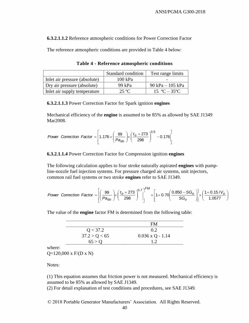
ANSI/PGMA G300-2018
© 2018 Portable Generator Manufacturers’ Association. All Rights Reserved.
40
6.3.2.1.1.2 Reference atmospheric conditions for Power Correction Factor
The reference atmospheric conditions are provided in Table 4 below:
Table 4 - Reference atmospheric conditions
Standard condition Test range limits
Inlet air pressure (absolute) 100 kPa -
Dry air pressure (absolute) 99 kPa 90 kPa – 105 kPa
Inlet air supply temperature 25 ºC 15 ºC – 35ºC
6.3.2.1.1.3 Power Correction Factor for Spark ignition engines
Mechanical efficiency of the engine is assumed to be 85% as allowed by SAE J1349
Mar2008.
176.0
298
27399176.1
5.0o
do
t
PaFactorCorrectionPower
6.3.2.1.1.4 Power Correction Factor for Compression ignition engines
The following calculation applies to four stroke naturally aspirated engines with pump-
line-nozzle fuel injection systems. For pressure charged air systems, unit injectors,
common rail fuel systems or two stroke engines refer to SAE J1349.
0577.1
/15.01850.070.01
298
273997.0
o
o
o
FM
o
do
V
SG
SGt
PaFactorCorrectionPower
The value of the engine factor FM is determined from the following table:
FM
Q < 37.2 0.2
37.2 > Q < 65 0.036 x Q - 1.14
65 > Q 1.2
where:
Q=120,000 x F/(D x N)
Notes:
(1) This equation assumes that friction power is not measured. Mechanical efficiency is
assumed to be 85% as allowed by SAE J1349.
(2) For detail explanation of test conditions and procedures, see SAE J1349.
ANSI/PGMA G300-2018
© 2018 Portable Generator Manufacturers’ Association. All Rights Reserved.
41
6.3.2.2 Documentation
The following information shall be recorded for each model tested:
Name and company of individual conducting test
Date of test
Name of product OEM
Model number/name/type
Rated wattage (W)
Rated voltage
Engine manufacturer/model
6.3.2.3 Test Equipment
6.3.2.3.1 Calibration
Test equipment identified in 6.3.2.3.2 shall be calibrated according to measuring
device manufacturer specifications and shall be traceable to National Institute of
Standards and Technology (NIST) methods or any equivalent national metrology
institute. The resistive elements in the load bank need not be calibrated.
The last date of calibration shall be clearly marked on each measuring device
6.3.2.3.2 Test Equipment Specifications
The manufacturer name and model number for all test equipment (measuring devices) shall
be recorded. The following test equipment shall be used:
Voltmeter capable of measuring true RMS voltage within at least +/- 1.5% of actual
Wattmeter capable of measuring true RMS wattage within at least +/- 3% of actual
Ammeter capable of measuring true RMS current within at least +/- 2.5% of actual
Frequency sensor capable of measuring within at least +/- 1% of actual
Load bank which applies a purely resistive load
Temperature meter +/- 2ºC (+/- 4ºF) of actual. For temperature measurements that
employ a thermocouple, a total tolerance of +/- 4.5º C (+/- 8º F) is allowed.
Barometer capable of measuring within at least +/- 1% of actual
Humidity meter +/- 5% of actual (wet bulb/dry bulb optional)
6.3.2.4 Test Procedure
Prepare unit(s) for test
o Unit may be broken in by running under varying load conditions for a period
as recommended by the engine manufacturer, but not to exceed 12 hours
o Engine oil shall be as recommended by manufacturer and shall be changed
after break in and before conducting tests
ANSI/PGMA G300-2018
© 2018 Portable Generator Manufacturers’ Association. All Rights Reserved.
42
Unit shall be tested in an open area which provides at least 1 meter of clearance on all
5 sides and a constant supply of fresh air
Ambient air temperature shall be 15-35ºC (59-95 ºF), measured 300 mm (12 inches)
from engine cooling air intake
The voltage shall be within 10% of the nameplate rated voltage and the frequency shall
be within 5% of the nameplate rated frequency for all loads from no-load to maximum
wattage
The portable generator shall be prepared and started in accordance with the operating
instructions. Start the unit and measure the voltage and frequency at no-load. If the
voltage or frequency is out of tolerance a minimum adjustment shall be made to the unit
to bring it into tolerance. For a mechanical governor system, the no-load frequency
should be adjusted to be between 62.5 and 63 Hertz
Load is to be applied to the unit while monitoring the voltage and frequency. Load
should be increased to the maximum available Observed Wattage output without
causing the voltage or frequency to fall out of tolerance. When the maximum wattage is
reached, the unit should be allowed to warm up until operating temperature has
stabilized. The unit is considered to be at temperature stabilization when the engine oil
temperature varies by less than 2°C (4°F) over 3 consecutive readings taken 15 minutes
apart. As the unit warms up, the load may need to be adjusted to maintain maximum
output wattage without exceeding voltage or frequency tolerances. Record voltage,
amperage, frequency, wattage, oil and ambient air temperature several times during the
test to show trends. When temperature stabilization has been reached record the
barometric pressure and the humidity
Calculate the Power Correction Factor based on the equation and standard conditions
in Table 4 using the temperature, barometric pressure and the humidity recorded when
the unit was at stable operating temperature
Calculate the Corrected Wattage by multiplying the Observed Wattage at temperature
stabilization by the Power Correction Factor
When testing units for compliance to this standard, Corrected Wattage at temperature
stabilization shall be a minimum of 90% of Nameplate Rated Wattage
6.4 Manufacturing Tests
The ambient air temperature requirements of 6.1 do not apply to this section.
All of the following tests shall be performed as "end-of-line " production tests on portable
generators:
6.4.1 Frequency setting
A portable generator which relies on engine speed for control of output frequency shall be
tested to confirm its frequency setting and, if necessary, adjust to the desired engine speed.
ANSI/PGMA G300-2018
© 2018 Portable Generator Manufacturers’ Association. All Rights Reserved.
43
The frequency setting shall be within 5% of the nameplate rating.
6.4.2 Power
All portable generators shall be tested to confirm their ability to produce at least 70% of its
rated output current.
6.4.3 Voltage
Each receptacle of a portable generator shall be tested to confirm that the correct nominal
voltage is present while the unit is operational. The measured voltage setting shall be within
10% of the nameplate rating.
6.4.4 Engine shutoff means
All portable generators shall be tested to confirm the correct operation of the engine shutoff
means.
6.4.5 Dielectric voltage withstand test
All portable generators shall pass the dielectric voltage withstand test of 6.2.9. The test may
be performed using 120% of the specified voltages applied for 1 second.
Note: The control box and portable generator may be tested separately before completing the
assembly.
6.4.6 Leakage testing
For portable generators that use LPG fuel, all hoses and fittings shall be tested after
assembly and proved free from leaks at not less than normal operating pressures. Tubing,
hoses and fittings shall be tested and proved free of leaks by applying a soap and water
solution to connection points and verifying that no bubbles appear, or other equivalent
means.
6.4.7 Portable generator system for controlling CO exposure
All portable generators shall be tested to confirm that the portable generator will shutoff
when an actual or simulated shutoff signal is introduced to the portable generator system for
controlling CO exposure.
7 Product and Packaging Labeling
7.1 Output Rating/Rating Plate
7.1.1 The portable generator output rating shall be included on packaging and reported per
6.3.2.
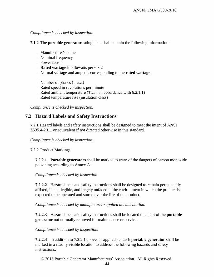
ANSI/PGMA G300-2018
© 2018 Portable Generator Manufacturers’ Association. All Rights Reserved.
44
Compliance is checked by inspection.
7.1.2 The portable generator rating plate shall contain the following information:
Manufacturer's name
Nominal frequency
Power factor
Rated wattage in kilowatts per 6.3.2
Normal voltage and amperes corresponding to the rated wattage
Number of phases (if a.c.)
Rated speed in revolutions per minute
Rated ambient temperature (TRated in accordance with 6.2.1.1)
Rated temperature rise (insulation class)
Compliance is checked by inspection.
7.2 Hazard Labels and Safety Instructions
7.2.1 Hazard labels and safety instructions shall be designed to meet the intent of ANSI
Z535.4-2011 or equivalent if not directed otherwise in this standard.
Compliance is checked by inspection.
7.2.2 Product Markings
7.2.2.1 Portable generators shall be marked to warn of the dangers of carbon monoxide
poisoning according to Annex A.
Compliance is checked by inspection.
7.2.2.2 Hazard labels and safety instructions shall be designed to remain permanently
affixed, intact, legible, and largely unfaded in the environment in which the product is
expected to be operated and stored over the life of the product.
Compliance is checked by manufacturer supplied documentation.
7.2.2.3 Hazard labels and safety instructions shall be located on a part of the portable
generator not normally removed for maintenance or service.
Compliance is checked by inspection.
7.2.2.4 In addition to 7.2.2.1 above, as applicable, each portable generator shall be
marked in a readily visible location to address the following hazards and safety
instructions:
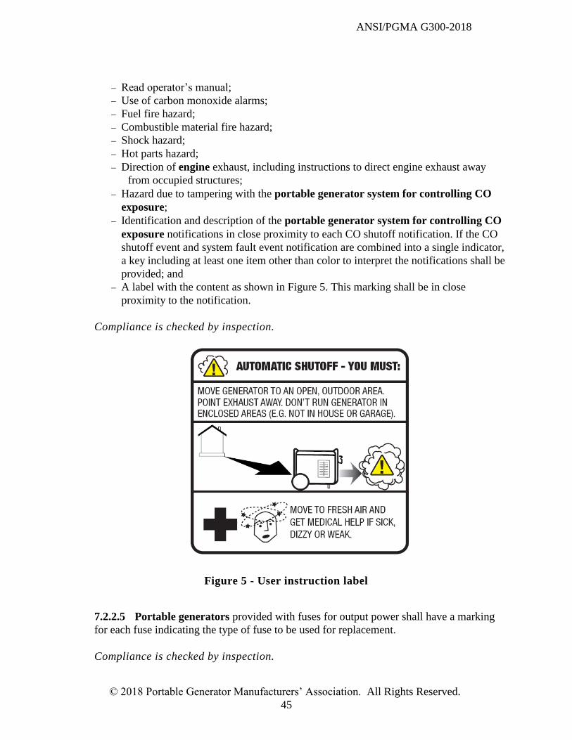
ANSI/PGMA G300-2018
© 2018 Portable Generator Manufacturers’ Association. All Rights Reserved.
45
Read operator’s manual;
Use of carbon monoxide alarms;
Fuel fire hazard;
Combustible material fire hazard;
Shock hazard;
Hot parts hazard;
Direction of engine exhaust, including instructions to direct engine exhaust away
from occupied structures;
Hazard due to tampering with the portable generator system for controlling CO
exposure;
Identification and description of the portable generator system for controlling CO
exposure notifications in close proximity to each CO shutoff notification. If the CO
shutoff event and system fault event notification are combined into a single indicator,
a key including at least one item other than color to interpret the notifications shall be
provided; and
A label with the content as shown in Figure 5. This marking shall be in close
proximity to the notification.
Compliance is checked by inspection.
Figure 5 - User instruction label
7.2.2.5 Portable generators provided with fuses for output power shall have a marking
for each fuse indicating the type of fuse to be used for replacement.
Compliance is checked by inspection.
ANSI/PGMA G300-2018
© 2018 Portable Generator Manufacturers’ Association. All Rights Reserved.
46
7.2.3 Packaging Markings
7.2.3.1 Portable generator packaging shall be marked to warn of the dangers of carbon
monoxide poisoning according to Annex A.
Compliance is checked by inspection.
7.2.3.2 Portable generator packaging shall be marked with a logo as shown in Figure 6
to indicate compliance with this standard.
Compliance is checked by inspection.
Figure 6 - Compliance logo
7.3 Grounding
7.3.1 Labeling shall include status of the AC neutral conductor, marked on each portable
generator, as follows:
NEUTRAL FLOATING; or
NEUTRAL BONDED TO FRAME.
This label shall be readily visible in the AC receptacle area(s). Where provision has been
made to connect or disconnect the neutral conductor from the portable generator frame, such
provision shall be clearly indicated in the marking.
ANSI/PGMA G300-2018
© 2018 Portable Generator Manufacturers’ Association. All Rights Reserved.
47
Compliance is checked by inspection.
7.3.2 Labeling shall include status of DC output receptacles (if provided), marked on each
portable generator, as follows:
SYSTEM FLOATING; or
SYSTEM BONDED TO FRAME.
This label shall be readily visible in the DC output receptacle area(s).
Compliance is checked by inspection.
7.3.3 The ground connection point on the portable generator shall be labeled with at least
one of the following:
a green color of the field grounding means described in subclause 5.6.3;
GROUND;
GND;
with the letters "G" or "GR";
clearly identified on a wiring diagram attached to the portable generator;
Symbol 5019 of IEC 60417 (see Figure 7);
The symbol ; or
Symbol 5020 of IEC 60417 (see Figure 8).
Compliance is checked by inspection.
ANSI/PGMA G300-2018
© 2018 Portable Generator Manufacturers’ Association. All Rights Reserved.
48
Figure 7 - Symbol 5019 of IEC 604174
Figure 8 - Symbol 5020 of IEC 604174
4 IEC 60417 Database Copyright © 2014 IEC Geneva, Switzerland. www.iec.ch
ANSI/PGMA G300-2018
© 2018 Portable Generator Manufacturers’ Association. All Rights Reserved.
49
7.3.3.1 If only symbol 5019 of IEC 60417 is used to identify the field grounding means,
then the following requirements also apply:
- the symbol shall be described in the instruction manual; and
- the symbol shall not be used at any location other than the field grounding means.
However, it is acceptable to use the symbol without the circle in locations other than the
field grounding means, to indicate points that are bonded to the portable generator frame.
Compliance is checked by inspection.
7.4 Packaging
Package labeling content is at the manufacturer’s discretion with the exception of markings as
detailed in 7.2.3. Performance ratings marked on the packaging shall be in accordance with the
test results of 6.3.
Compliance is checked by inspection.
8 Operators Manual, Operating Instructions and Warnings
8.1 A portable generator shall be provided with an operator’s manual that includes
specifications, assembly, operation, maintenance, moving and storage instructions and carbon
monoxide alarm requirements as applicable. Instructions pertaining to the risk of carbon
monoxide poisoning, fire, shock or other personal injury hazards associated with the portable
generator shall also be provided.
Compliance is checked by inspection.
8.2 Product safety information shall be presented per ANSI Z535.6- 2011 or equivalent if not
directed otherwise in this standard.
Compliance is checked by inspection.
8.3 Status of the Neutral Conductor
8.3.1 For portable generators where the neutral is bonded to the frame, the operator’s
manual shall include the following wording or equivalent:
There is a permanent conductor between the portable generator stator winding and the
frame.
Compliance is checked by inspection.
8.3.2 For portable generators where the neutral is bonded to the frame and where provision
has been made to connect or disconnect the neutral conductor from the machine frame, such
provision shall be indicated. This indication may be satisfied by an instruction to contact the
ANSI/PGMA G300-2018
© 2018 Portable Generator Manufacturers’ Association. All Rights Reserved.
50
manufacturer.
Compliance is checked by inspection.
8.3.3 For portable generators where the neutral is floating, the operator’s manual shall
include the following wording or equivalent:
The portable generator stator winding is isolated from the frame and from the AC
receptacle ground pin; and
Electrical devices that require a connection between one conductor pin and the grounded
receptacle pin may not function properly.
Compliance is checked by inspection.
8.4 Assembly instructions shall be provided as applicable.
Compliance is checked by inspection.
8.5 For portable generators that use LPG fuel, recommended LP tank sizes shall be provided.
Compliance is checked by inspection.
8.6 Operation
The operator’s manual shall include the following instructions for operation:
Where to locate the portable generator for safe operation (e.g. carbon monoxide, fire,
electrocution), including generator placement outdoors, far away from windows, doors and
vents, with engine exhaust directed away from occupied structures;
Use of carbon monoxide alarm(s) with battery backup installed according to the alarm
manufacturer’s instructions;
Identification of product hazard labels and their locations as applicable;
Identification of controls, features, handles, lifting means and a description of their use as
applicable;
Proper electrical cord selection information as applicable;
Portable generator inspection and any accessory items for damage prior to use (e.g. fuel
system, receptacles, exhaust system, wiring, extension cords), and to repair/ replace as
applicable;
Specific fuel, oil and coolant specifications, including capacities required, as applicable;
How to start, operate and stop the portable generator;
Battery specifications as applicable;
Connection of the product to a building’s electrical system, as applicable. These
instructions shall include the need for a transfer switch installed by licensed electricians
who are approved by the authority having jurisdiction. The installation must comply with
all applicable laws and electrical codes;
ANSI/PGMA G300-2018
© 2018 Portable Generator Manufacturers’ Association. All Rights Reserved.
51
Notifications of the portable generator system for controlling CO exposure and, as
applicable, maintenance or service requirements;
User instructions following a carbon monoxide shutdown event, including relocation of the
portable generator prior to restart and addressing symptoms of CO poisoning.
Compliance is checked by inspection.
8.7 Maintenance
8.7.1 Instructions shall be provided for installation, inspection or replacement of items
intended to be serviceable by the user (e.g. oil change, filters, fuel valve, spark arrester, spark
plug, battery, fuse, engine cooling system) as applicable.
Compliance is checked by inspection.
8.7.2 Instructions shall be provided for cleaning and care of the portable generator, as
applicable.
Compliance is checked by inspection.
8.8 Storage
Information shall be provided on recommended short term and long term storage procedures, as
applicable.
Compliance is checked by inspection.
8.9 A troubleshooting guide shall be provided as applicable.
Compliance is checked by inspection.
9 Normative References
ANSI/ASHRAE 62.2-2016,Ventilation and Acceptable Indoor Air Quality in Low-Rise
Residential Buildings
ANSI/NEMA MW 1000 - 2016, Magnet Wire
ANSI/NEMA WD 6 - 2016, Wiring Devices - dimensional specifications
ANSI/OPEI B71.10 - 2013, Off-Road Ground-Supported Outdoor Power Equipment -
Gasoline Fuel Systems - Performance Specifications and Test Procedures
ANSI/UL 94, March 2013, Tests for Flammability of Plastic Materials for Parts in Devices
and Appliances
ANSI/UL 569, November 2013, Standard for Pigtails and Flexible Hose Connectors for LP-
Gas
ANSI/PGMA G300-2018
© 2018 Portable Generator Manufacturers’ Association. All Rights Reserved.
52
ANSI/UL 746C, September 2004, Polymeric Materials - Use in Electrical Equipment
Evaluations
ANSI/UL 796, May 2016, Standard for Printed-Wiring Boards
ANSI/UL 943, May 2016, Ground-Fault Circuit-Interrupters
ANSI/UL 1439, April 2015, Standard for Tests for Sharpness of Edges on Equipment
ANSI/UL 1446, November 2016, Systems of Insulating Materials - General
ANSI/UL 2034, March 2017, Single and Multiple Station Carbon Monoxide Alarms
ANSI/UL 60034-1: July 2016, Rotating electrical machines - Part 1: Rating and
performance
ANSI Z21.81-2005, Cylinder Connection Devices
ANSI Z535.4-2011, Product Safety Signs and Labels
ANSI Z535.6-2011, Product Safety Information in Product Manuals, Instructions, and
Other Collateral Materials
Code of Federal Regulations, Title 16, Part 1407
Code of Federal Regulations, Title 40, Part 1054
CSA C22.2 No 100-14, Motors and Generators
IEC 60085: 2007, Electrical Insulation - Thermal evaluation and designation
IEC 60417, Graphical symbols for use on equipment
IEC 60529: 1989, Degrees of protection provided by enclosures (IP Code)
IEC 61032: 1997, Protection of persons and equipment by enclosures - Probes for
verification
IPC-2221B, November 2012, Generic Standard on Printed Board Design
NFPA 70, National Electrical Code, 2017 Edition
SAE J1349, September 2011, Engine Power Test Code - Spark Ignition and Compression
Ignition - Net Power Rating. ANSI/UL 94, March 2013, Tests for Flammability of Plastic
Materials for Parts in Devices and Appliances
UL 2201, March 2009, Standard for Safety - Portable Engine-Generator Assemblies
USDA Forest Service Standard 5100-1d, February 2013, Standard for Spark Arrestors
for Internal Combustion Engines
ANSI/PGMA G300-2018
© 2018 Portable Generator Manufacturers’ Association. All Rights Reserved.
53
Annex A (normative)
Product markings
Please note that what follows is a copy of the Consumer Product Safety Commission’s
requirements for portable generators from the Code of Federal Regulations.
PART 1407—PORTABLE GENERATORS: REQUIREMENTS TO PROVIDE
PERFORMANCE AND TECHNICAL DATA BY LABELING
Sec.
1407.1 Purpose, scope, and effective date.
1407.2 Definitions.
1407.3 Providing performance and technical data to purchasers by labeling.
Figure 1 to Part 1407—On-product carbon monoxide poisoning hazard label
Figure 2 to Part 1407—Safety alert symbol
Figure 3 to Part 1407—Carbon monoxide poisoning hazard label for package
Authority: 15 U.S.C. 2076(e).
Source: 72 FR 1450, Jan. 12, 2007, unless otherwise noted.
§ 1407.1 Purpose, scope, and effective date.
This part 1407 establishes requirements under section 27(e) of the Consumer Product Safety Act
(15 U.S.C. 2076(e)) for manufacturers to provide consumers with a specified notification
concerning the carbon monoxide poisoning hazard associated with the use of portable generators.
The notification is intended to provide consumers with technical and performance information
related to the safety of portable generators. This part applies to any generator manufactured or
imported on or after May 14, 2007.
§ 1407.2Definitions.
(a) The definitions in section 3 of the Consumer Product Safety Act (15 U.S.C. 2052) apply to
this part 1407.
(b) A portable generator is an internal combustion engine-driven electric generator rated no
higher than 15 kilowatts and 250 volts that is intended to be moved for temporary use at a
location where utility-supplied electric power is not available. It has receptacle outlets for the
alternating-current (AC) output circuits, and may have alternating- or direct-current (DC)
sections for supplying energy to battery charging circuits.
§ 1407.3Providing performance and technical data to purchasers by labeling.
(a) Notice to purchasers. Manufacturers of portable generators shall give notification of
performance and technical data related to performance and safety to prospective purchasers of
such products at the time of original purchase and to the first purchaser of such product for
purposes other than resale, in the manner set forth below.
(1) On-product label. The CO poisoning hazard label shown in Figure A.1 shall be used on the
product. A different representation of the generator may be substituted for accuracy if consumers
ANSI/PGMA G300-2018
© 2018 Portable Generator Manufacturers’ Association. All Rights Reserved.
54
are more likely to recognize the substituted representation as the generator to which this label is
affixed. Alternate-language versions of this label may appear on the product in addition to the
label specified in Figure A.1. If the product label is also provided by the manufacturer in
additional language(s), it shall appear adjacent to or below the English-language version of the
product label, and shall be no larger than the English-language version of the label. Versions of
the product label that are in a language other than English may appear without the pictograms
that appear in the English-language versions.
(i) The signal word “DANGER” shall be in letters not less than 0.15 inch (3.8 mm) high. The
remaining text shall be in type whose uppercase letters are not less than 0.1 inch (2.5 mm) high.
(ii) The signal word “DANGER” shall appear in white letters on a safety red background. The
safety alert symbol shown in Figure A.2 shall appear immediately before and next to the signal
word and be no smaller than the height of the signal word with the base of the triangle on the
same horizontal line as the base of the signal word. The solid portion of the triangle (within the
lines of the triangle, around the exclamation mark) shall be white and the exclamation mark shall
be safety red. The prohibition circle-slash symbols shall be opaque.
(iii) The on-product hazard label shown in Figure A.1 shall be located:
(A) On a part of the portable generator that cannot be removed without the use of tools, and
(B) On a location that is prominent and conspicuous to an operator while performing at least two
of the following actions: Filling the fuel tank, accessing the receptacle panel, and starting the
engine.
(iv) The on-product hazard label shown in Figure A.1 shall be designed to remain permanently
affixed, intact, legible, and largely unfaded in the environment in which the product is expected
to be operated and stored over the life of the product.
(2) Carbon monoxide poisoning hazard label for package. The CO poisoning hazard label shown
in Figure A.3 shall be affixed to the principal display panel(s) of the package, as well as the
surface containing the top flaps of the package. The principal display panel(s) of the package is
the portion(s) of the outer packaging that is designed to be most prominently displayed, shown,
presented, or examined under conditions of retail sale. Any panel of the package that includes
text in a language other than English shall also include a CO poisoning hazard label in that
language. Alternate-language versions of the label, in addition to the label specified in Figure
A.3, may also appear on the top flaps of the package as long as they are physically separate from
one another. A different representation of the generator may be substituted for accuracy if
consumers are more likely to recognize the substituted representation as the generator contained
within the packaging.
(i) The signal word “DANGER” shall be in letters not less than 0.15 inch (3.8 mm) high. The
remaining text shall be in type whose uppercase letters are not less than 0.1 inch (2.5 mm) high.
(ii) The signal word “DANGER” shall appear in white letters on a safety red background. The
safety alert symbol shown in Figure A.2 shall appear immediately before and next to the signal
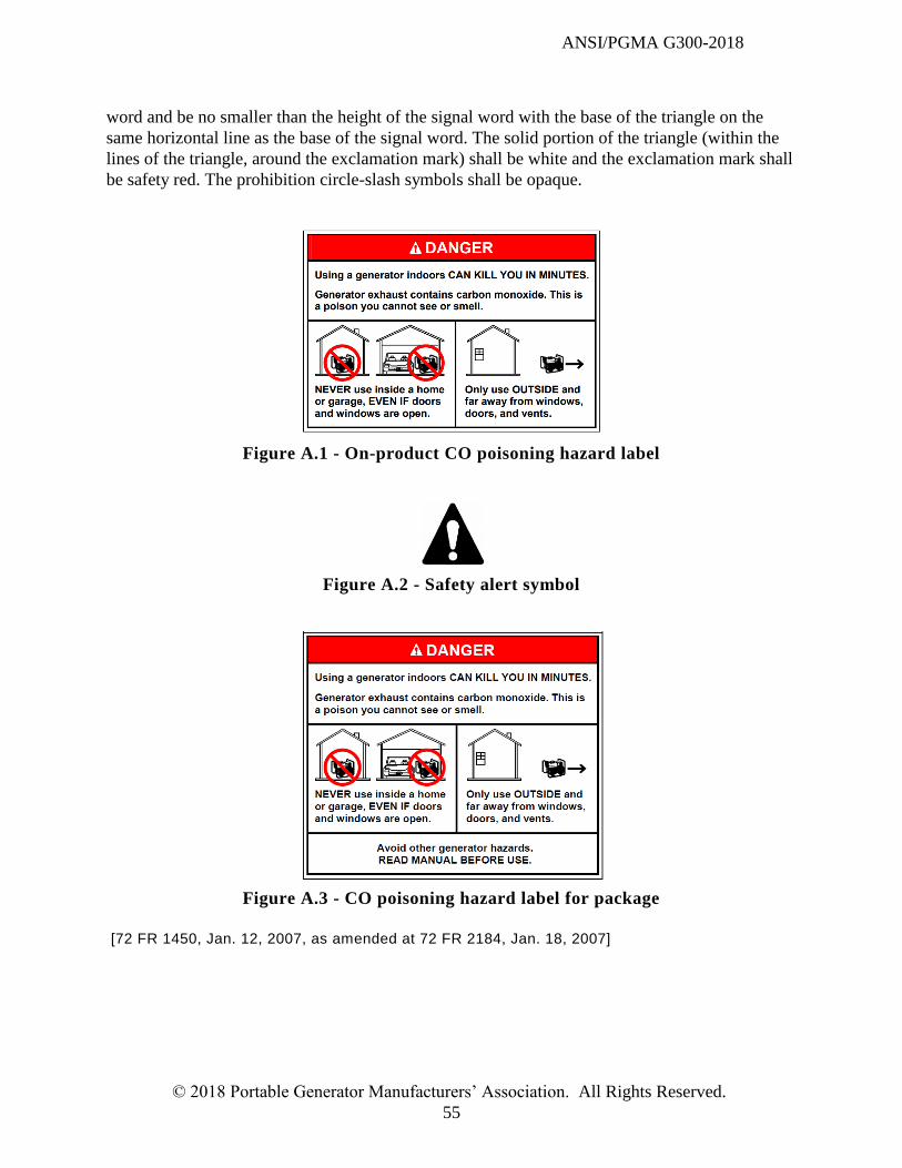
ANSI/PGMA G300-2018
© 2018 Portable Generator Manufacturers’ Association. All Rights Reserved.
55
word and be no smaller than the height of the signal word with the base of the triangle on the
same horizontal line as the base of the signal word. The solid portion of the triangle (within the
lines of the triangle, around the exclamation mark) shall be white and the exclamation mark shall
be safety red. The prohibition circle-slash symbols shall be opaque.
Figure A.1 - On-product CO poisoning hazard label
Figure A.2 - Safety alert symbol
Figure A.3 - CO poisoning hazard label for package
[72 FR 1450, Jan. 12, 2007, as amended at 72 FR 2184, Jan. 18, 2007]
ANSI/PGMA G300-2018
© 2018 Portable Generator Manufacturers’ Association. All Rights Reserved.
56
PGMA – The Portable Generator Manufacturers' Association is North America’s leading
trade association of manufacturers of portable generators. With Association headquarters
based in Cleveland, Ohio, our member companies include the major manufacturers of
portable generators sold in North America. Since we represent a significant majority of the
industry, we are the recognized voice of the portable generator industry.
For more information about the Portable Generator Manufacturers Association, contact:
PGMA
1300 Sumner Avenue
Cleveland, OH 44115-2851
Phone: (216) 241-7333
Fax: (216) 241-0105
E-Mail: [email protected]
URL: www.pgmaonline.com