Embed Size (px)
Citation preview
NASA SP-5928 (02)
CASE F' COPY
SAFETY AND MAINTENANCE ENGINEERING
A COMPILATION
https://ntrs.nasa.gov/search.jsp?R=19740022277 2020-04-15T06:28:17+00:00Z
Foreword
The National Aeronautics and Space Administration and Atomic Energy Commission have established a Technology Utilization Program for the rapid dissemination of infor- mation on technological developments which have potential utility outside the aerospace and nuclear communities. By encouraging multiple application of the results of their research and development, NASA and AEC earn for the public an increased return on the investment in aerospace and nuclear research and development programs.
This publication is part of a series intended to provide such technical information and is divided into three sections. Section one is devoted to technology that involves the safety of personnel engaged in the handling and use of hazardous material and equipment plus a novel device to increase the safety of blind persons as they move about. The second section deals with devices and materials that protect equipment from hazards posed by fire, high wind, or careless handling by user personnel. Section three presents a number of items covering engineering devices and techniques devoted to the maintenance of operating equipment.
Additional technical information on individual devices and techniques can be re- quested by circling the appropriate number on the Reader Service Card included in this Compilation.
Patent Statements reflect the latest information available at the final preparation of this Compilation. For those innovations on which NASA and AEC have decided not to apply for a patent, a Patent Statement is not included. Potential users of items described herein should consult the cognizant organization for updated patent information at that time.
Patent information is included with several articles. For the reader's convenience, this information is repeated, along with more recently received information on other items, on the page following the last article in the text.
We appreciate comment by readers and welcome hearing about the relevance and utility of the information in this Compilation.
Jeffrey T. Hamilton, Director Technology Utilization Office National Aeronautics and Space Administration
NOTICE s This document was prepared under the sponsorship of the National Aeronautics and Space Administration. Neither the United States Government nor any person acting on behalf of the United States Government assumes any liability resulting from the use of the information contained in this document, or warrants that such use will be free from privately owned rights.
For sale by the National Technical Information Service, Springfield, Virginia 22151.
Contents
Page SECTION 1 . PERSONNEL SAFETY TECHNOLOGY
. . . . . . . . . . . . . . . . . . . . . . . . . . . New Cane for the Blind: A Concept 1
. . . . . . . . . . . . . . . . . . . . . . . . . . . Improved Protective Helmet Assembly 2 . . . . . . . . . . . . . . . . . . . . . . . . . Safety Restraint for HighPressure Hose 3
. . . . . . . . . . . . . . . . . . . . . . . . . . . . . . . Safety-Lock Equipment Hook 4
. . . . . . . . . . . . . . . . . . . . . . . . . . . . . . . Quick-Opening Hatch System 4 . . . . . . . . . . . . . . . . . . . . . . . . . . . Self-Braking Device for Escape Cable 6
Pneumatic Safety Raft . . . . . . . . . . . . . . . . . . . . . . . . . . . . . . . . . . . . . 7 . . . . . . . . . . . . . . . . . . . . . . . Liquid Oxygen and Hydrogen Safety Study 8
SECTION 2 . EQUIPMENT SAFETY TECHNOLOGY Megger Test Safety Device . . . . . . . . . . . . . . . . . . . . . . . . . . . . . . . . . . . 8 Dry-Frictional Shock Absorber . . . . . . . . . . . . . . . . . . . . . . . . . . . . . . . 9
. . . . . . . . . . . . . . . . . . . . . . . . . Polymers for Fireproofing Applications 10 . . . . . . . . . . . . . . . . . . . . . . . . . . . . . . . Safety System for Test Facility 10
Low G-Force and Frequency Shock Attenuation in Towed Vehicles . . . . . . . 11 . . . . . . . . . . . . . . . . . . . . . . . . . . . . . Fire Extinguisher Control System 12
. . . . . . . . . . . . . . . . . . . . . . . Safety AdapterITester for Electrical Circuits 13 . . . . . . . . . . . . . . . . . . . Vibration Reduced by Post-Stressing of Concrete 14
Remote Handling Device for Hazardous Materials . . . . . . . . . . . . . . . . . . . 15 Remote Manipulation in High Vacuum Using
. . . . . . . . . . . . . . . . . . . . . . . . . . . . . . . . . MasterISlave Manipulators 16 . . . . . . . . . . . . . . . . . . . . . . . . . . . . . Improved Fire-Ressitant Coatings 17
. . . . . . . . . . . . . . . . . . . . . . . Protective Cap for Thermocouple Junction 18 . . . . . . . . . . . . . . . . . . . . . . . . . . . Oscillation Damper for Tall Structures 18
SECTION 3 . MAINTENANCE ENGINEERING Lamp Automatically Switches to New Filament on
. . . . . . . . . . . . . . . . . . . . . . . . . . . . . . . . . . . Burnout: A Concept 19 . . . . . . . . . . . . . . . . . . . . . . . Maintenance Ladder with Integral Platform 20 . . . . . . . . . . . . . . . . . . . . . . . Repair Technique for Plastic Pushbuttons 21
. . . . . . . . . . . . . . . . . . . TV System for Monitoring Remote Manipulations 22 . . . . . . . . . . . . . . . . . . . . . . . . . . . Ladder Holder for Tank Maintenance 23
. . . . . . . . . . . . . . . . . . . . . . . . . . . . . Device Detects Submerged Leaks 24
PATENTINFORMATION . . . . . . . . . . . . . . . . . . . . . . . . . . . . . . . . . . . . . 25
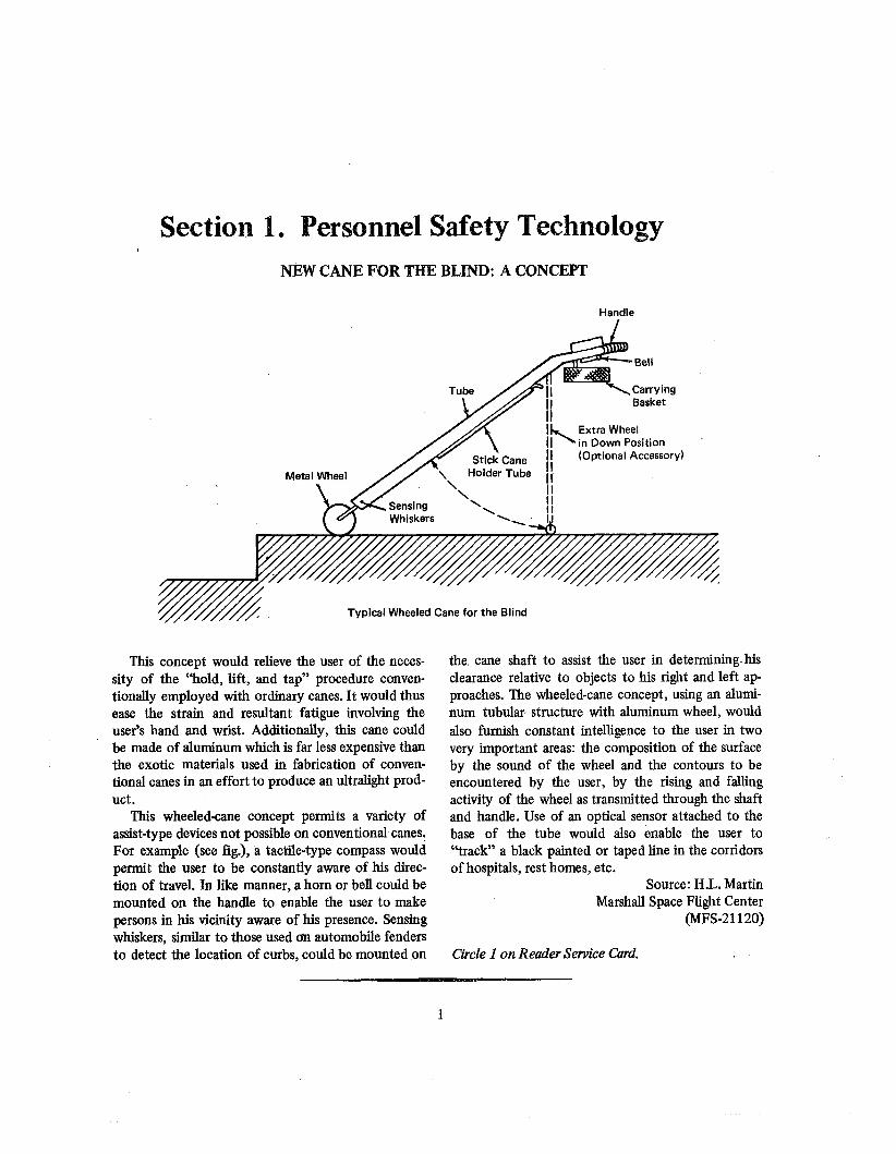
Section 1. Personnel Safety Technology NEW CANE FOR THE BLIND: A CONCEPT
Handle
in Down Position
Typical Wheeled Cane for the Blind
This concept would relieve the user of the neces- sity of the "hold, lift, and tap" procedure conven- tionally employed with ordinary canes. It would thus ease the strain and resultant fatigue involving the user's hand and wrist. Additionally, thii cane could be made of aluminum which is far less expensive than the exotic materials used in fabrication of conven- tional canes in an effort to produce an ultralight prod- uct.
This wheeled-cane concept permits a variety of assist-type devices not possible on conventional canes. For example (see fig.), a tactile-type compass would permit the user to be constantly aware of his direc- tion of travel. In like manner, a horn or bell could be mounted on the handle to enable the user to make persons in his vicinity aware of his presence. Sensing whiskers, similar to those used an automobile fenders to detect the location of curbs, could be mounted on
the. cane shaft to assist the user in determining-his clearance relative to objects to his right and left ap- proaches. The wheeled-cane concept, using an alumi- num tubular structure with aluminum wheel, would also furnish constant intelligence to the user in two very important areas: the composition of the surface by the sound of the wheel and the contours to be encountered by the user, by the rising and falling activity of the wheel as transmitted through the shaft and handle. Use of an optical sensor attached to the base of the tube would also enable the user to "track" a black painted or taped line in the corridors of hospitals, rest homes, etc.
Source: H.L. Martin Marshall Space Flight Center
(MFS-21120)
Circle I on Reader Service Card.
SAFETY AND MAINTENANCE ENGINEERING
IMPROVED PROTECTIVE HELMET ASSEMBLY
/ Polycarbonate Shell Helmet Insert Pr~tection Pad \
Head Pad
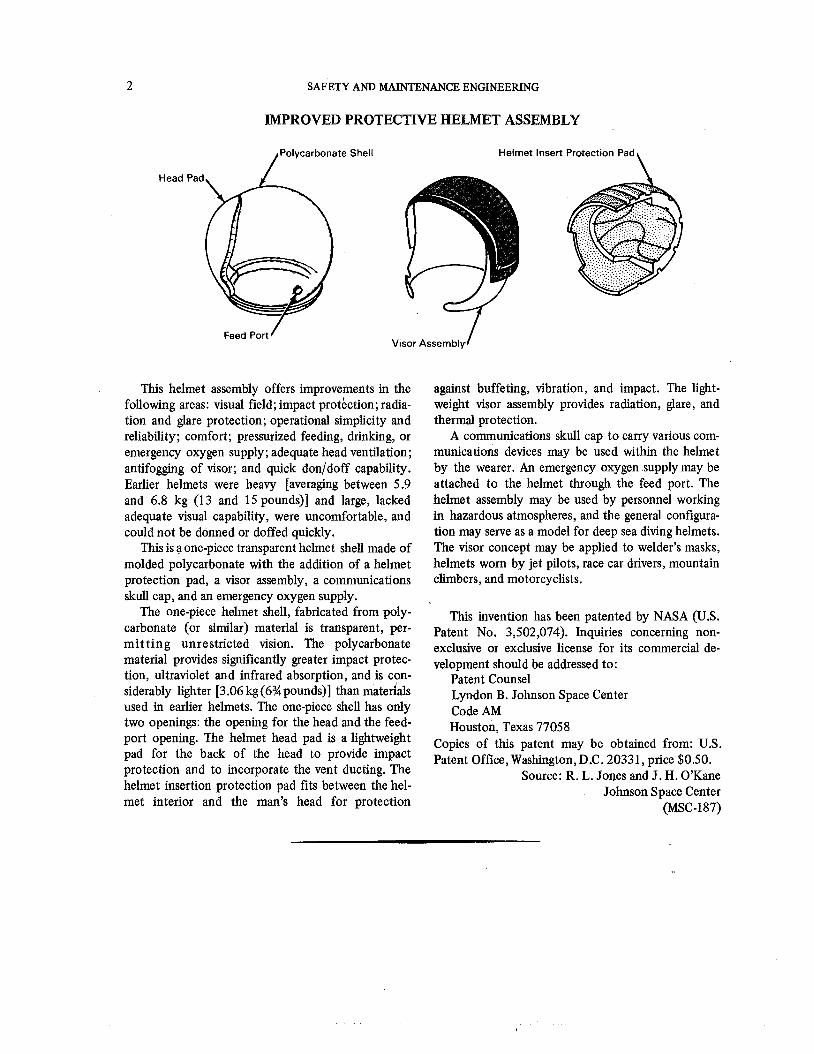
This helmet assembly offers improvements in the following areas: visual field; impact protkction; radia- tion and glare protection; operational simplicity and reliability; comfort; pressurized feeding, drinking, or emergency oxygen supply; adequate head ventilation; antifogging of visor; and quick donldoff capability. Earlier helmets were heavy [averaging between 5.9 and 6.8 kg (13 and 15 pounds)] and large, lacked adequate visual capability, were uncomfortable, and could not be donned or doffed quickly.
This is a one-piece transparent helmet shell made of molded polycarbonate with the addition of a helmet protection pad, a visor assembly, a communications skull cap, and an emergency oxygen supply.
The one-piece helmet shell, fabricated from poly- carbonate (or similar) material is transparent, per- mit t ing unrestricted vision. The polycarbonate material provides significantly greater impact protec- tion, ultraviolet and infrared absorption, and is con- siderably lighter [3.06 kg (63/4 pounds)] than matedals used in earlier helmets. The one-piece shell has only two openings: the opening for the head and the feed- port opening. The helmet head pad is a lightweight pad for the back of the head to provide impact protection and to incorporate the vent ducting. The helmet insertion protection pad fits between the hel- met interior and the man's head for protection
against buffeting, vibration, and impact. The light- weight visor assembly provides radiation, glare, and thermal protection.
A communications skull cap to carry various corn- munications devices may be used within the helmet by the wearer. An emergency oxygen supply may be attached to the helmet through the feed port. The helmet assembly may be used by personnel working in hazardous atmospheres, and the general configura- tion may serve as a model for deep sea diving helmets. The visor concept may be applied to welder's masks, helmets worn by jet pilots, race car drivers, mountain climbers, and motorcyclists.
This invention has been patented by NASA (U.S. Patent No. 3,502,074). Inquiries concerning non- excl~sive or exclusive license for its commercial de- velopment should be addressed to:
Patent Counsel Lyndon B. Johnson Space Center Code AM Houston, Texas 77058
Copies of this patent may be obtained from: U.S. Patent Office, Washington, D.C. 20331, price $0.50.
Source: R. L. Jones and J. H. OYKane Johnson Space Center
(MSC-187)
PERSONNEL SAFETY TECHNOLOGY 3
SAFETY RIESTRAIW FOR HGHPESSUIRE HOSE
Restraint Used With High-Pressure Hose
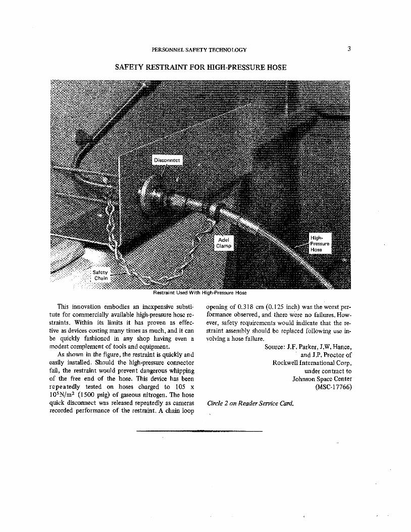
This innovation embodies an inexpensive substi- tute for commercially available high-pressure hose re- straints. Within its limits it has proven as effec- tive as devices costing many times as much, and it can be quickly fashioned in any shop having even a modest complement of tools and equipment.
As shown in the figure, the restraint is quickly and easily installed. Should the high-pressure connector fail, the restraint would prevent dangerous whipping of the free end of the hose. This device has been repeatedly tested on hoses charged to 105 x 105N/m2 (1500 psig) of gaseous nitrogen. The hose quick disconnect was released repeatedly as cameras recorded performance of the restraint. A chain loop
opening of 0.3 18 cm (0.125 inch) was the worst per- formance observed, and there were no failures. How- ever, safety requirements would indicate that the re- straint assembly should be replaced following use in- volving a hose failure.
Source: J.F. Parker, J.W. Hance, and J.P. Proctor of
Rockwell International Corp. under contract to
Johnson Space Center (MSC-17766)
Circle 2 on Reader Service Card.
SAFETY AND MAINTENANCE ENGINEERING
SAFETY-LOCK EQUIPMENT HOOK
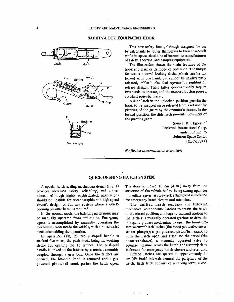
This new safety hook, although designed for use by astronauts to tether themselves to their spacecraft while in space, should be of interest to manufacturers of safety, sporting, and camping equipment.
The illustration shows the main features of the hook and clarifies its mode of operation. The unique feature is a novel locking device which can be un- locked with one hand, but cannot be inadvertently released, unlike hooks that operate by pushbutton release designs. These latter devices usually require two hands to operate, and the exposed button poses a constant potential hazard.
A slide latch in the unlocked position permits the hook to be snapped on or released from a retainer by pivoting of the guard by the operator's thumb. In the locked position, the slide latch prevents movement of the pivoting guard.
Source: R.J. Eggers of Rockwell International Corp.
under contract to Johnson Space Center
Section A-A (MSC- 17341)
No further documentation is available
QUICK-OPENING HATCH SYSTEM
A special hatch sealing mechanism design (Fig. 1) provides increased safety, reliability, and conve- nience. Although highly sophisticated, adaptations should be possible for oceanographic and high-speed aircraft design, or for any system where a quick- opening pressure hatch is required.
In the normal mode, the hatching mechanism may be manually operated from either side. Emergency egress is accomplished by manually operating the mechanism from inside the vehicle, with a boost-assist mechanism aiding the operation.
In operation (Fig. 2), the push-pull handle is stroked five times, the push stroke being the working stroke for opening the 15 latches. The push-pull handle is linked to the latches by a ratchet assembly coupled through a gear box. Once the latches are opened, the lock-pin knob is removed and a gas- powered pistonlbell crank pushes the hatch open.
The door is moved 10 cm (4 in.) away from the structure of the vehicle before being swung open for immediate egress. A screwjack attachment is included for emergency hatch closure and retention.
The unified hatch contains the following mechanical components: latches to retain the hatch in the closed position; a linkage to transmit motion to the latches; a manually operated gearbox to drive the linkage; a plunger mechanism to open the boost-pro- tective cover-hatch latches (the boost-protective cover- striker plunger); a gas powered pikon/bell crank to - push the hatch open and attenuate the travel (the counterbalance); a manually operated valve to equalize pressure across the hatch; and a screwjack at- tachment for emergency hatch closure and-retention. .
Fifteen latches are spaced at approximately 14 cm (5% inch) intervals around the periphery of the hatch. Each latch consists of a driving lever, a con-
PERSONNEL SAFETY TECHNOLOGY
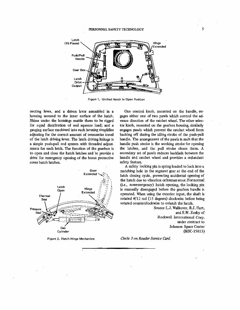
Figure 1. Unified Hatch In Open Position
necting lever, and a driven lever assembled in a housing secured to the inner surface of the hatch. Shims under the housings enable them to be rigged for equal distribution of seal squeeze load; and a gauging surface machined into each housing simplifies adjusting for the correct amount of overcenter travel of the latch driving lever. The latch driving linkage is a simple push-pull rod system with threaded adjust- ments for each latch. The function of the gearbox is to open and close the hatch latches and to provide a drive for emergency opening of the boost protective cover hatch latches.
Door Extended \T12
11' 1 1 1
Latch Open
I
. - - <
Hinge ,, Extended 1,' !,'
as Cylinder
One control knob, mounted on the handle, en- gages either one of two pawls which control the ad- vance direction of the ratchet wheel. The other selec- tor knob, mounted on the gearbox housing, similarly engages pawls which prevent the ratchet wheel from backing off during the idling stroke of the push-pull handle. The arrangement of the pawls is such that the handle push stroke is the working stroke for opening the latches, and the pull stroke closes them. A secondary set of pawls reduces backlash between the handle and ratchet wheel and provides a redundant safety feature.
A safety locking pin is spring loaded to lock into a matching hole in the segment gear at the end of the latch closing cycle, preventing accidental opening of the hatch due to vibration or human error. For normal (i.e., nonemergency) hatch opening, the locking pin is manually disengaged before the gearbox handle is operated. When using the exterior input, the shaft is rotated ~ 1 1 2 rad (1 5 degrees) clockwise before being rotated counterclockwise to unlatch the hatch.
S0urce:L.J. Walkover, R.J. Hart, and E.W. Zosky of
Rockwell International Corp. under contract to
Johnson Space Center (MSC-15813)
Figure 2. Hatch Hinge Mechanism Circle 3 on Reader Service Card.
SAFETY AND MAINTENANCE ENGINEERING
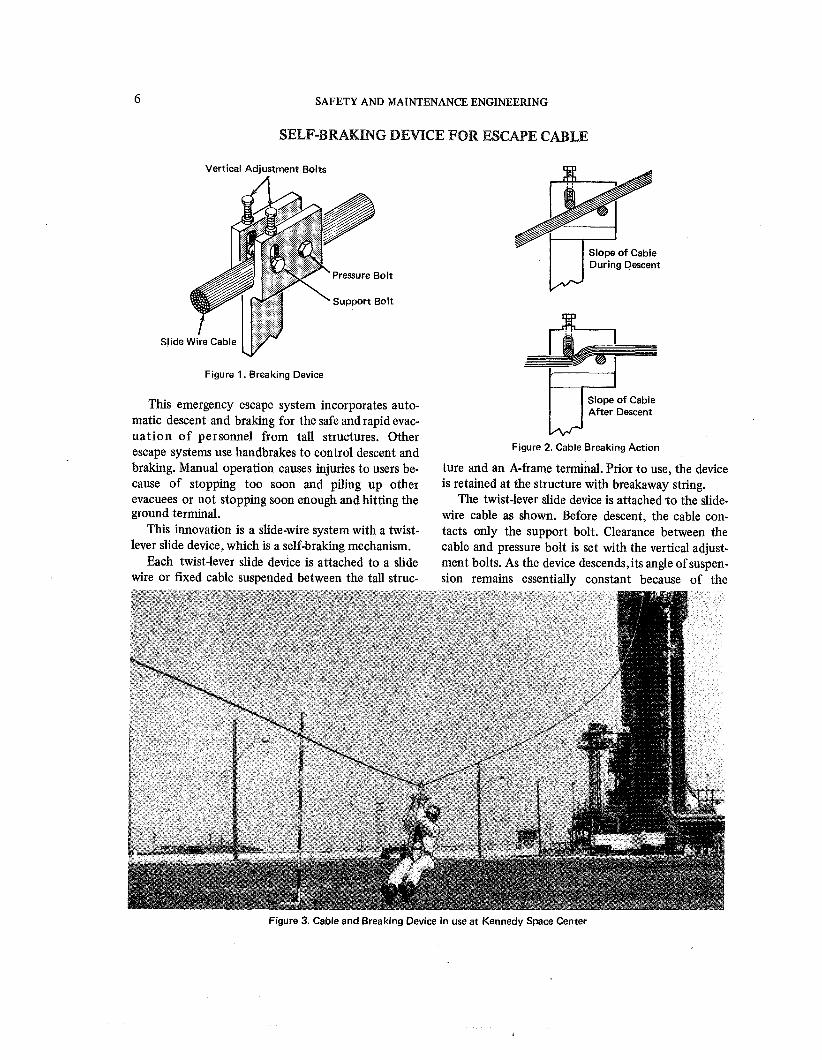
SELF-BRAKING DEVICE FOR ESCME CABLE
Vertical Adjustment Bolts
Figure 1. Breaking Device
This emergency escape system incorporates auto- matic descent and braking for the safe and rapid evac- uat ion of personnel from tall structures. Other escape systems use handbrakes to control descent and braking. Manual operation causes injuries to users be- cause of stopping too soon and piling up other evacuees or not stopping soon enough and hitting the ground terminal.
This innovation is a slide-wire system with a twist- lever slide device, which is a self-braking mechanism.
Each twist-lever slide device is attached to a slide wire or fured cable suspended between the tall struc-
1-1 During Descent
Slope of Cable After Descent
Figure 2. Cable Breaking Action
ture and an A-frame terminal. Prior to use, the device is retained at the structure with breakaway string.
The twist-lever slide device is attached t o the slide- wire cable as shown. Before descent, the cable con- tacts only the support bolt. Clearance between the cable and pressure bolt is set with the vertical adjust- ment bolts. As the device descends, its angle of suspen- sion remains essentially constant because of the
Figure 3. Cable and Breaking Device in use at Kennedy Space Center
PERSONNEL SAFETY TECHNOLOGY 7
attached load. The slide wire cable has a decreasing angle of slope, and as the slope decreases, the cable eventually contacts the pressure bolt. The resultant twisting of the cable forces the device to a smooth, but rapid, stop.
The initial clearance setting between the cable and the pressure bolt determines the eventual stopping point of the twist-lever slide device. Field experimen- tation will quickly determine proper adjustment bolt settings for stopping at a predetermined point.
To evacuate the structure, each person hooks a personal sling-type harness to one of the twist lever slide devices. The person's weight breaks the string retaining the device, and it descends along the slide
wire. The device automatically stops at ground level before reaching the A-frame terminal.
This system is presently in operation at John F. Kennedy Space Center. The automatic descent and braking features permit evacuation of unconscious or injured personnel. This device could be used on any tall structure that might require emergency evacua- tion. It could also be used to transfer materials and equipment.
Source: C.R. Billings, R.A. McDaris, J.T. McGough, and P.F. Neal
Kennedy Space Center (KSC-66-44)
Circle 4 on Reader Service Card.
PNEUMATIC SAFETY RAFT
Expandable Sock
Inflated
I I .-1 Floor 1 .-. 1
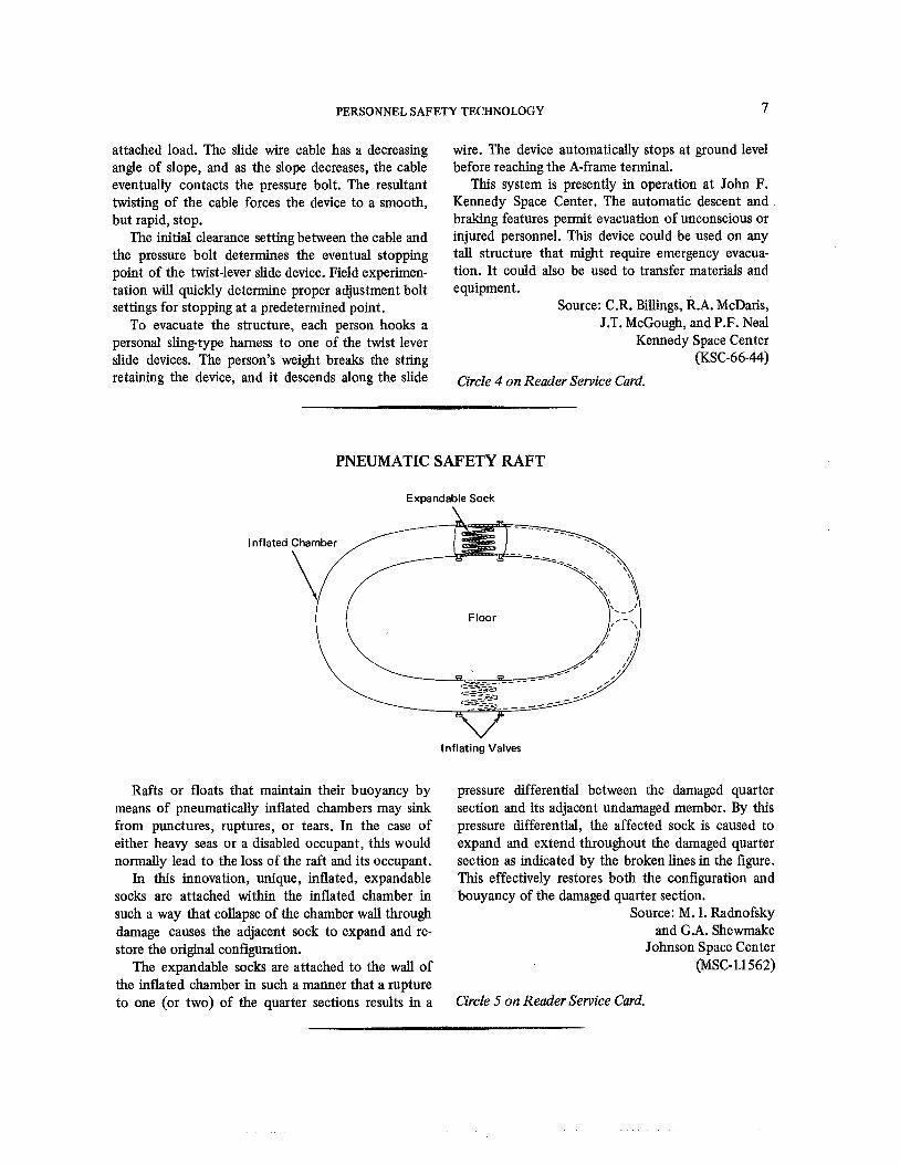
Rafts or floats that maintain their buoyancy by means of pneumatically inflated chambers may sink from punctures, ruptures, or tears. In the case of either heavy seas or a disabled occupant, this would normally lead to the loss of the raft and its occupant.
In this innovation, unique, inflated, expandable socks are attached within the inflated chamber in such a way that collapse of the chamber wall through damage causes the adjacent sock to expand and re- store the original configuration.
The expandable socks are attached to the wall of the inflated chamber in such a manner that a rupture to one (or two) of the quarter sections results in a
Inflating Valves
pressure differential between the damaged quarter section and its adjacent undamaged member. By this pressure differential, the affected sock is caused to expand and extend throughout the damaged quarter section as indicated by the broken lines in the figure. This effectively restores both the configuration and bouyancy of the damaged quarter section.
Source: M. I. Radnofsky and G.A. Shewrnake
Johnson Space Center (MSC-1.1562)
Circle 5 on Reader Service Card.
8 SAFETY AND MAINTENANCE ENGINEERING
LIQUID OXYGEN AND HYDROGEN SAFETY STUDY
This study has been made in an effort to establish safe handling of liquid hydrogen and liquid oxygen by presenting those characteristics of these two energy sources that most contribute to their inherent dangerous natures. Such germane characteristics as the properties, physiological effects, safe handling, contamination with other fluids, fire and explosion hazards, burning velocity, and deflagrations plus det- onations of liquid hydrogen are fully investigated.
The study covers liquid oxygen in a less metic- ulous manner, but hkludes its general properties, its
unpredictable sensitivity in the presence of contarni- nants (especially hydrocarbons), general hazards, prob- lems in storage and transfer, and the special handling required for its transportation.
Source: E.C. Savage of McDomell Douglas Corp.
under contract to Marshall Space Flight Center
(MFS-21568)
Circle 6 on Reader Service Card.
Section 2. Equipment Safety Technology
MEGGER TEST SAFETY DEVICE
Megohmmeter Harness
Connector
Megohm Resistor
Structure
L I Typical I nsulation-Resistance Test Hookup
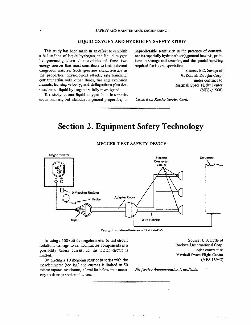
In using a 500-volt dc megohmmeter to test circuit Source: C.F. Lytle of isolation, damage to semiconductor components is a Rockwell.1ntemational Corp. possibility unless current in the meter circuit is under contract to limited. Marshall Space Flight Center
By placing a 10 megohrn resistor in series with the (MFS- 16945) megohmmeter (see fig.) the current is limited to 50 microamperes maximum, a level far below that neces- No further documentation is available. -
sary to damage semiconductors.
EQUIPMENT SAFETY TECHNOLOGY
DRY-FRIICTIONAL SHOCK DSOIPBER
Cyllndrlcal Body Brake Sleeve
I
Sleeve-Expander Spr~ng Load Resl'stlng
Projection-Y Sprlng Bore (Cyl~nder)
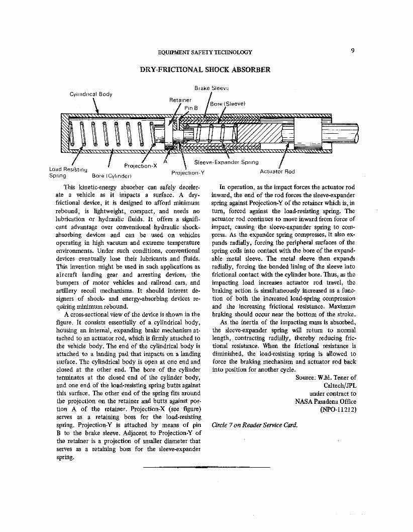
This kinetic-energy absorber can safely deceler- ate a vehicle as it impacts a surface. A dry- frictional device, it is designed to afford minimum rebound, is lightweight, compact, and needs no lubrication or hydraulic fluids. It offers a signifi- cant advantage over conventional hydraulic shock- absorbing devices and can be used on vehicles operating in high vacuum and extreme temperature environments. Under such conditions, conventional devices eventually lose their lubricants and fluids. This invention might be used in such applications as aircraft landing gear and arresting devices, the bumpers of motor vehicles and railroad cars, and artillery recoil mechanisms. It should interest de- signers of shock- and energy-absorbing devices re- quiring minimum rebound.
A cross-sectional view of the device is shown in the figure. It consists essentially of a cylindrical body, housing an internal, expanding brake mechanism at- tached to an actuator rod, which is firmly attached to the vehicle body. The end of the cylindrical body is attached to a landing pad that impacts on a landing surface. The cylindrical body is open at one end and closed at the other end. The bore of the cylinder terminates at the closed end of the cylinder body, and one end of the load-resisting spring butts against this surface. The other end of the spring fits around the projection on the retainer and butts against por- tion A of the retainer. Projection-X (see figure) serves as a retaining boss for the load-resisting spring. Projection-Y is attached by means of pin B to the brake sleeve. Adjacent to Projection-Y of the retainer is a projection of smaller diameter that serves as a retaining boss for the sleeve-expander spring.
In operation, as the impact forces the actuator rod inward, the end of the rod forces the sleeve-expander spring against Projection-Y of the retainer which is, in turn, forced against the load-resisting spring. The actuator rod continues to move inward from force of impact, causing the sleeve-expander spring to com- press. As the expander spring compresses, i t also ex- pands radially, forcing the peripheral surfaces of the spring coils into contact with the bore of the expand- able metal sleeve. The metal sleeve then expands radially, forcing the bonded lining of the sleeve into frictional contact with the cylinder bore. Thus, as the impacting load increases actuator rod travel, the braking action is simultaneously increased as a func- tion of both the increased load-spring compression and the increasing frictional resistance. Maximum braking should occur near the bottom of the stroke.
As the inertia of the impacting mass is absorbed, the sleeve-expander spring will return to normal length, contracting radially, thereby reducing fric- tional resistance. When the frictional resistance is diminished, the load-resisting spring is allowed to force the braking mechanism and actuator rod back into position for another cycle.
Source: WM. Tener of CaltechIJPL
under contract to NASA Pasadena Office
@Po-1 1212)
Circle 7 on Reader Service Card.
SAFETY AND MAINTENANCE ENGINEERING
NASA has developed two new polymers for use in fireproofing applications. These will be of interest to manufacturers of fire resistant and safety equipment; specifically they may well find a use in the produc- tion of fireproofed home furnishings.
Both of the new polymers were developed to pro- vide a fabric which will protect astronauts from fire hazards in the oxygen enriched atmosphere of a spacecraft. In one, the basic molecule of poly-2,2 bis (3, 5-dibromo-4-hydroxyphenyl) perfluoropropane carbonate is formed d y replacing the aliphatic hydro- gens in tetrabromobis phenol-A-polycarbonate with fluorine. The second new polymer, poly-3, 3, 5, 5 tetrabromo-4-4-dihydroxybenzophenone carbonate, is also based on tetrabromobis phenol-A-polycar-
bonate, but in this instance the isopropylidene bridge is replaced by a carbonyl function.
Tested as coating on glass fibers, neither polymer would bum when ignited in a 42 x lo3 hJ/m2 (6.2 psia) oxygen atmosphere.
Source: A. Y. Garner, A. E. Follett, and
J. M. Butler of Monsanto Research Corp.
under contract to Johnson Space Center
(MSC-13769 and MSC-13770)
No fitrther documentation is available.
SAFETY SYSTEM FOR TEST FACHLIITY
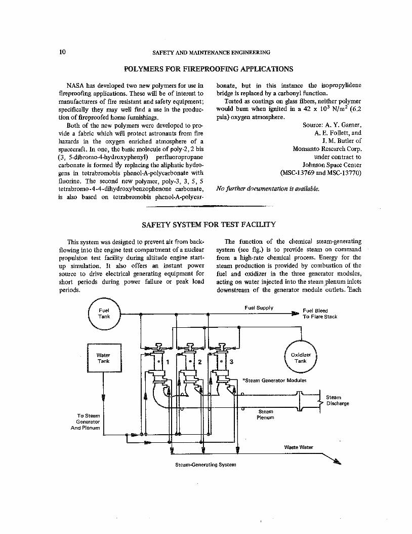
This system was designed to prevent air from back- The function of the chemical steam-generating flowing into the engine test compartment of a nuclear system (see fig.) is to provide steam on command propulsion test facility during altitude engine start- from a high-rate chemical process. Energy for the up simulation. It also offers an instant power steam production is provided by combustion of the source to drive electrical generating equipment for fuel and oxidizer in the three generator modules, short periods during power failure or peak load acting on water injected into the steam plenum inlets periods. downstream of the generator module outlets. Tach
Steam-Generating System A
EQUIPMENT SAFETY TECHNOLOGY 11
generator module is capable of 29.5 kglsec (65-lb/sec) of steam at 980 ~ ( 1 3 0 0 ~ F) and incorporates control, safety, and sequence equipment that permit it to operate independently or integrally with either or both of the other modules.
Fuel and oxidizer used successfully were propane and liquid oxygen, respectively, but with system modification they could be changed to a long te rn storable propellant such as N2O4, a hypergolic
fuel which would result in increased reliability and system simplicity, but at a sacrifice in system safety.
Source: H. Henze of Aerojet-General Corp.
under contract to Space Nuclear Systems Office
(NUC-10037) Circle 8 on Reader Service Card.
LOW GFOWCE AMD Fm(BUENCY SHOCK ATTENUATION WT TOWD VEWICLES
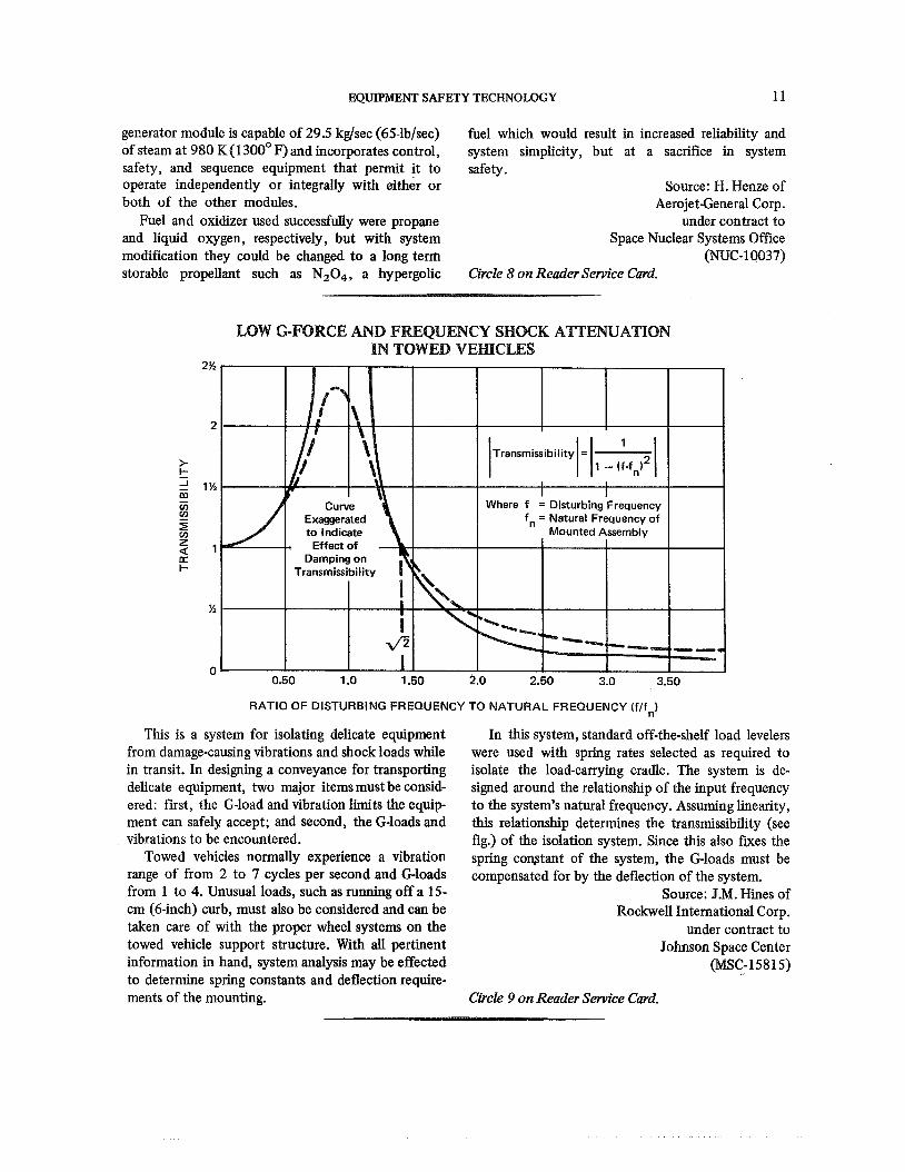
RATIO OF DISTURBING FREQUENCY TO NATURAL FREQUENCY (flf,)
This is a system for isolating delicate equipment from damage-causing vibrations and shock loads while in transit. In designing a conveyance for transporting delicate equipment, two major items must be consid- ered: first, the G-load and vibration limits the equip- ment can safely accept; and second, the G-loads and vibrations to be encountered.
Towed vehicles normally experience a vibration range of from 2 to 7 cycles per second and Gloads from 1 to 4. Unusual loads, such as running off a 15- cm (6-inch) curb, must also be considered and can be taken care of with the proper wheel systems on the towed vehicle support structure. With all pertinent information in hand, system analysis may be effected to determine spring constants and deflection require- ments of the mounting.
In this system, standard off-the-shelf load levelers were used with spring rates selected as required to isolate the load-carrying cradle. The system is de- signed around the relationship of the input frequency to the system's natural frequency. Assuming linearity, this relationship determines the transmissibility (see fig.) of the isolation system. Since this also fures the spring cowtant of the system, the Gloads must be compensated for by the deflection of the system.
Source: J.M. Hines of Rockwell International Corp.
under contract to Johnson Space Center
(MSC-15815)
Circle 9 on Reader Service Card.
SAFETY AND MAINTENANCE ENGINEERING
FIRE EXTINGUISHER CONTROL SYSTEM
Fait-Dry Handvalve
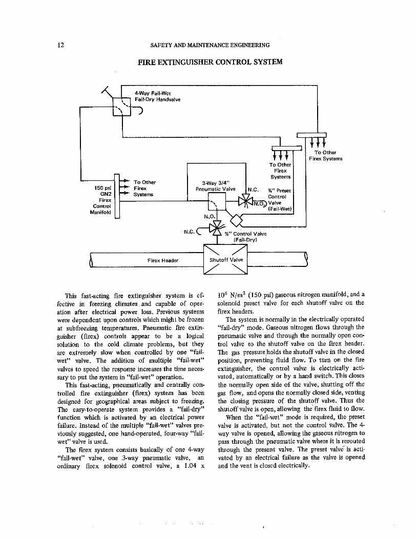
This fast-acting fire extinguisher system is ef- fective in freezing climates and capable of oper- ation after electrical power loss. Previous systems were dependent upon controls which might be frozen at subfreezing temperatures. Pneumatic fire extin- guisher (firex) controls appear to be a logical solution to the cold climate problems, but they are extremely slow when controlled by one "fail- wet" valve. The addition of multiple "fail-wet" valves to speed the response increases the time neces- sary to put the system in "fail-wet" operation.
This fast-acting, pneumatically and centrally con- trolled fire extinguisher (firex) system has been designed for geographical areas subject to freezing. The easy-to-operate system provides a "fail-dry" function which is activared by an electrical power failure. Instead of the multiple "fail-wet" valves pre- viously suggested, one hand-operated, four-way "fail- wet" valve is used.
The firex system consists basically of one 4-way "fail-wet" valve, one 3-way pneumatic valve, an ordinary firex solenoid control valve, a 1.04 x
lo6 ~ / m ~ (150 psi) gaseous nitrogen manifold, and a solenoid preset valve for each shutoff valve on the firex headers.
The system is normally in the electrically operated "fail-dry" mode. Gaseous nitrogen flows through the pneumatic valve and through the normally open con- trol valve to the shutoff valve on the firex header. The gas pressure holds the shutoff valve in the closed position, preventing fluid flow. To turn on the fire extinguisher, the control valve is electrically acti- vated, automatically or by a hand switch. This closes the normally open side of the valve, shutting off the gas flow, and opens the normally closed side, venting the closing pressure of the shutoff valve. Thus the shutoff valve is open, allowing the' firex fluid to flow.
When the "fail-wet" mode is required, the preset valve is activated, but not the control valve. The 4- way valve is opened, allowing the gaseous nitrogen to pass through the pneumatic valve where it is rerouted through the present valve. The preset valve is acti- vated by an electrical failure as the valve is opened and the vent is closed electrically.
EQUIPMENT SAFETY TECHNOLOGY 13
Thus, if the electrical power fails, the open side oS the preset valve closes, stopping the nitrogen gad flow to the shutoff valve. The vent side opens, vent- ing the closing pressure of the shutoff valve, and al- lowing the fire extinguisher fluid to flow. '
Source: J.C. Branum of North American Aviation, Inc.
under contract to Marshall Space Flight Center
(MFS-13031)
Circle 10 on Reader Service Card.
SAFETY ADAPTERITESTER FOR ELECTRICAL CIRCUITS
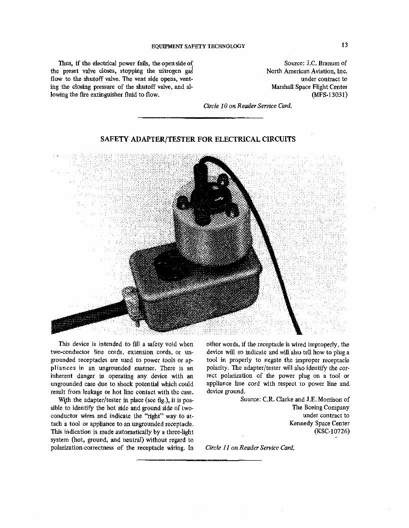
This device is intended to fill a safety void when two-conductor line cords, extension cords, or un- grounded receptacles are used to power tools or ap- pliances in an ungrounded manner. There is an inherent danger in operating any device with an ungrounded case due to shock potential which could result from leakage or hot line contact with the case.
With the adapterltester in place (see fig.), it is pos- sible to identify the hot side and ground side of two- conductor wires and indicate the "right" way to at- tach a tool or appliance to an ungrounded receptacle. This indication is made automatically by a three-light system (hot, ground, and neutral) without regard to polarization-correctness of the receptacle wiring. In
other words, if the receptacle is wired improperly, the device will so indicate and will also tell how to plug a tool in properly to negate the improper receptacle polarity. The adapterltester will also identify the cor- rect polarization of the power plug on a tool or appliance line cord with respect to power line and device ground.
Source: C.R. Clarke and J.E. Morrison of The Boeing Company
under contract to Kennedy Space Center
(KSC-10726)
Circle 11 on Reader Service Card.
SAFETY AND MAINTENANCE ENGINEERING
WBWATION REDUCED BY POST-STESSING OF CONCRETE
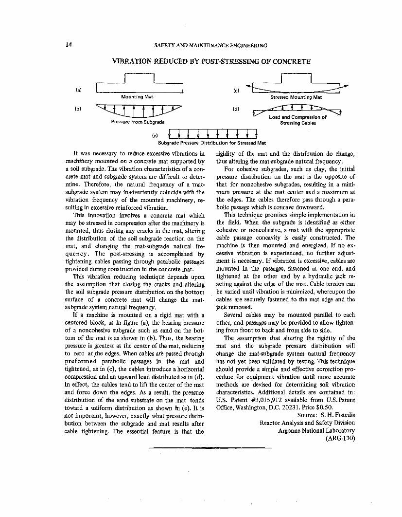
(a) I 1 Mounting Mat
Pressure from Subgrade
Stressed Mounting Mat
Stressing Cables
(el Subgrade Pressure Distribution for Stressed Mat
It was necessary to reduce excessive vibrations in machihery mounted on a concrete mat supported by a soil subgrade. The vibration characteristics of a con- crete mat and subgrade system'are difficult to deter- mine. Therefore, the natural frequency of a mat- subgrade system may inadvertently coincide with the vibration frequency of the mounted machinery, re- sulting in excessive reinforced vibration.
This innovation involves a concrete mat which may be stressed in compression after the machinery is mounted, thus closing any cracks in the mat, altering the distribution of the soil subgrade reaction on the mat, and changing the mat-subgrade natural fre- quency. The post-stressing is accomplished by tightening cables passing through parabolic passages provided during construction in the concrete mat.
This vibration reducing technique depends upon the assumption that closing the cracks and altering the soil subgrade pressure distribution on the bottom ~
surface of a concrete mat will change the mat- subgrade system natural frequency.
If a machine is mounted on a rigid mat with a centered block, as in figure (a), the bearing pressure of a noncohesive subgrade such as sand on the bot- tom of the mat is as shown in (b). Thus, the bearing pressure is greatest at the center of the mat, reducing to zero at ,the edges. When cables are passed through preformed parabolic passages in the mat and tightened, as in (c), the cables introduce a horizontal compression and an upward load distributed as in (d). In effect, the cables tend to lift the center of the mat and force down the edges. As a result, the pressure distribution of the sand substrate on the mat tends toward a uniform distribution as shown h (e). It is not important, however, exactly what pressure distri- bution between the subgrade and mat results after cable tightening. The essential feature is that the
rigidity of the mat and the distribution do change, thus altering the mat-subgrade natural frequency.
For cohesive subgrades, such as clay, the initial pressure distribution on the mat is the opposite of that for noncohesive subgrades, resulting in a mini- mum pressure at the mat center and a maximum at the edges. The cables therefore pass through a para- bolic passage which is concave downward.
This technique promises simple implementation in the field. When the subgrade is identified as either cohesive or noncohesive, a mat with the appropriate cable passage concavity is easily constructed. The machine is then mounted and energized. If no ex- cessive vibration is experienced, no further adjust- ment is necessary. If vibration is excessive, cables are mounted in the passages, fastened at one end, and tightened at the other end by a hydraulic jack re- acting against the edge of the mat. Cable tension can be varied until vibration is minimized, whereupon the cables are securely fastened to the mat edge and the jack removed.
Several cables may be mounted parallel to each other, and passages may be provided to allow tighten- ing from front to back and from side to side.
The assumption that altering the rigidity of the mat and the subgrade pressure distribution will change the mat-subgrade system natural frequency has not yet been validated by testing. This technique should provide a simple and effective correction pro- cedure for equipment vibration until more accurate methods are devised for detedning soil vibration characteristics. Additional details are contained in: U.S. Patent #3,015,912 available from U.S.Patent Office, Washington, D.C. 20231. Price $0.50.
Source: S. H. Fistedis Reactor Analysis and Safety Division
Argonne National ~aboratory (ARG-130)
EQUIPMENT SAFETY TECHNOLOGY
OTE HANDLING DEVICE FOR HAZARDOUS MATEMALS
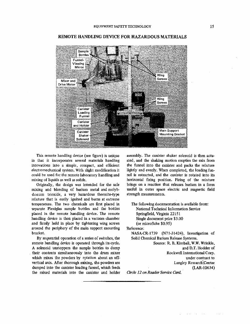
This remote handling device (see figure) is unique in that it incorporates several materials handling innovations into a simple, compact, and efficient electromechanical system. With slight modification it could be used for the remote laboratory handling and mixing of liquids as well as solids.
Originally, the design was intended for the safe mixing and blending of barium metal and molyb- denum trioxide, a very hazardous thermite-type mixture that is easily ignited and bums at extreme temperature. The two chemicals are first placed in separate Plexiglas sample bottles and the bottles placed in the remote handling device. The remote handling device is then placed in a vacuum chamber and firmly held in place by tightening wing screws around the periphery of the main support mounting bracket.
By sequential operation of a series of switches, the remote handling device is operated through its cycle. A solenoid unstoppers the sample bottles to dump their contents simultaneously into the drum mixer which mixes the powders by r9tation about an off- vertical axis. After thorough mixing, the powders are dumped into the canister loading funnel, which feeds the mixed materials into the canister and holder
assembly. The canister shaker solenoid is then actu- ated, and the shaking motion empties the mix from the funnel into the canister and packs the mixture lightly and evenly. When completed, the'loading fun- nel is retracted, and the canister is rotated into its horizontal firing position. Firing of the mixture brbgs on a reaction that releases barium in a form useful in outer space electric and magnetic field strength measurements.
The following documentation is available from: National Technical Information Service Springfield, Virginia 22 15 1 Single document price $3.00 (or microfiche $0.95)
Reference : NASACR-1739 (N7 1-3 1424), Investigation of Solid Chemical Barium Release Systems.
Source: R. B. Kimball, W.W. Wrinkle, and D.T. Hodder of
Rockwell International Corp. under contract to
Langley ~esearch\Center (LAR- 10634)
Circle 12 on Reader Service Card.
SAFETY AND W E N A N C E ENGINEERING
REMOTE MANIPULATION IN HIGH VACUUM USING MASTER/SLAVE MANIPULATORS
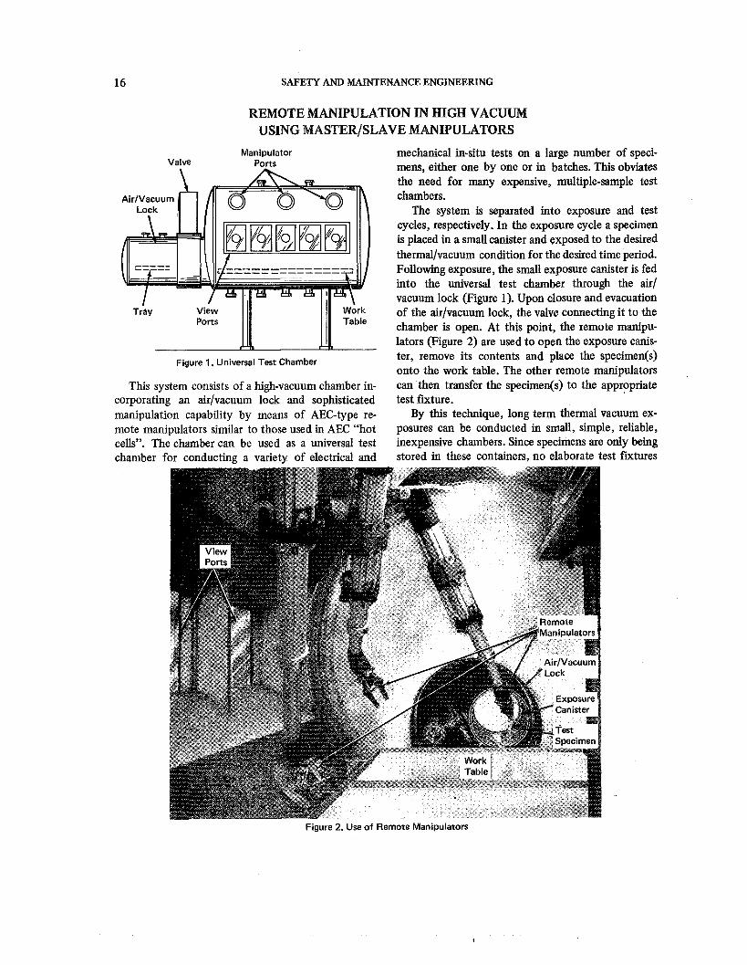
Manipulator Valve Ports
Figure 1. Universal Test Chamber
This system consists of a high-vacuum chamber in- corporating an air/vacuum lock and sophisticated manipulation capability by means of AEC-type re- mote manipulators similar to those used in AEC "hot cells". The chamber can be used as a universal test chamber for conducting a variety of electrical and
mechanical in-situ tests on a large number of speci- mens, either one by one or in batches. This obviates the need for many expensive, multiple-sample test chambers.
The system is separated into exposure and test cycles, respectively. In the exposure cycle a specimen is placed in a small canister and exposed to the desired thermal/vacuum condition for the desired timeperiod. Following exposure, the small exposure canister is fed into the universal test chamber through the air/ vacuum lock (Figure 1). Upon closure and evacuation of the airlvacuum lock, the valve connecting it to the chamber is open. At this point, the remote manipu- lators (Figure 2) are used to open the exposure canis- ter, remove its contents and place the specimen(s) onto the work table. The other remote manipulators can then transfer the specimen($) to the appropriate test furture.
By this technique, long term thermal vacuum ex- posures can be conducted in small, simple, reliable, inexpensive chambers. Since specimens are only being stored in these containers, no elaborate test furtures
-- Figure 2. Use of Remote Manipulators
EQUIPMENT SAFETY TECHNOLOGY 17
or complex electrical or mechanical feedthroughs are required in these systems. The universal test chamber, conversely, contains only one test furture for a given test and can be altered, modified, or repaired between tests so as not to compromise any of the long term exposed samples.
The success of this technique has come through the development of mechanical manipulators com- patible with high vacuum. With these manipulators, one essentially has a vacuum chamber with a "main-
tenance man" and "technician" available for working within the vacuum chambers at all times.
Source: S. Podlaseck of Martin Marietta Corp.
under contract to Langley Research Center
(LAR- 10673)
No further documentation is available.
MPROVED FIRE-RIESISTANT COATINGS
New formulations for fire-resistant water-base coatings containing potassium silicate show consid- erable improvement in the areas of quick airdrying; crack, craze, and abrasion resistance; adherence; and leach resistance (water insolubility). The coatings should prove particularly useful as thermal-barrier layers in furnaces and as general purpose fire-resis- tant surfaces where vapor impermeability is not a re- quirement.
The basic composition of the coatings are as fol- lows: 3680 parts (by weight) P o t a s s i u m silicate
(K2Si03) and water solu- tion, containing 10-24% (by weight) of solids with Si02/K2 mol ratio of 4.8 to 5.3.
1-10 parts (by weight) Ceric oxide and an alkyl trialkoxy silane ( e . g . , m e t h y l tri- methoxy silane), the mixture of which acts as a leach retardant (or rehydration suppres- sant).
5-15 parts (by weight) Fibrous calcium silicate (wollas tonite), which acts as a crack and craze retardant.
Up to 10 parts (by weight) of a supplemental binder-filer, consisting of talc and/or kaolinite, may be added to any of these components. This filer would be most desirable where fast furnace drying is preferred or where the composition is to be applied to structures subjected to high temperatures.
Pigments such as carbon black, cadmium sulfide, and the oxides of titanium, iron, copper, chromium, and manganese may also be added.
This invention has been patented by NASA (U.S. Patent No. 3,493,401). Inquiries concerning non- exclusive or exclusive license for its commercial de- velopment should be addressed to:
Patent Counsel Goddard Space Flight Center Code 204 Greenbelt, Maryland 20771
Copies of this patent may be obtained from: U.S. Patent Office, Washington, D.C. 20231, price $0.50.
Source: J. B. Schutt and J. W. Stuart Goddard Space Flight Center
(GSC-10072)
SAFETY AND MAINTENANCE ENGINEERING
PROTE(;THW CAP FOR THEWOCOUBLE
Rigid Plastic
Thermofit SCL Shrink Tubing
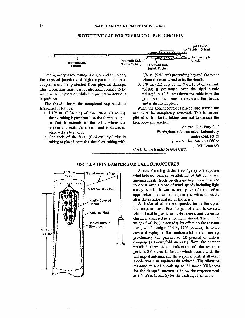
During acceptance testing, storage, and shipment, 318 in. (0.96 cm) protruding beyond the point the exposed junctions of high-temperature thermo- where the sensing end exits the sheath. couples must be protected from physical damage. 3. 718 in. (2.2 cm) of the %-in. (0.64-cm) shrink This protection must permit electrical contact to be tubing is positioned over the rigid plastic made with the junctionwhile the protective device is tubing 1 in. (2.54 cm) down the cable from the in position. point where the sensing end exits the sheath,
The sketch shows the completed cap which is and is shrunk in place. fabricated as follows: When the thermocouple is placed into service the
1. 1-118 in. (2.86 cm) of the 118-in. (0.32-cm) cap must be completely removed. This is accom- shrink tubing is positioned on the thermocouple plished with a knife, taking care not to damage the so that it extends to the point where the thermocouple junction. sensing end exits the sheath, and is shrunk in Source: C.A. Fatyol of place with a heat gun. Westinghouse Astronuclear Laboratory
2. One inch of the %-in. (0.64-cm) rigid plastic under contract to tubing is placed over the shrunken tubing with Space Nuclear Systems Office
(NUC-90078) Circle 13 on Reader Service Card.
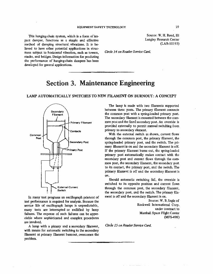
OSCILLATION DAMPER FOR TALL STRUCTURES A new damping device (see figure) will suppress
wind-induced bending oscillations of tall cylindrical antenna masts. Such oscillations have been observed t o occur over a range of wind speeds including light steady winds. It was necessary to rule out other approaches that would require guy wires or would
Plastic Covered alter the exterior surface of the mast. A cluster of chams is suspended inside the tip of
the antenna mast. Each length of chain is covered Antenna Mast with a flexible plastic or rubber sleeve, and the entire
cluster is enclosed in a neoprene shroud. The damper Conical Shroud weighs 5.40 kg (1 2 pounds). Its effect on the antenna
38.1 cm mast, which weighs 118 kg (261 pounds), is to in-
(15 in.) crease damping of the fundamental mode from a p
1 proximately 0.5 percent to 10 hercent of critical damping (a twentyfold increase). With the damper installed, there is no indication of the response peak at 2.6 mlsec (5 knots) which occurs with the undamped antenna, and the response peak at al l other speeds was also si&cantly reduced. The vibration response at wind speeds up to 31 m/sec (60 knots) for the damped antenna is below the response peak at 2.6 mlsec (5 knots) for the undamped antenna.
EQUIPMENT SAFETY TECHNOLOGY 19
This hanging-chain system, which is a form of im- Source: W. H. Reed, 111 pact damper, functions as a simple and effective Langley Research Center method of damping structural,vibrations. It is be- (LAR-10193) lieved to have other potential applications in struc- tures subject to horizontal vibration, such as towers, GpcZe 14 on Reader Card. stacks, and bridges. Design information for predicting the performance of hangingchain dampers'has been developed for general applications.
Section 3. Maintenance Engineering
I t M P A1DTFOUTICALLY SWTCmS TO m W HLNIENT ON BURNOUT: A CONCEPg
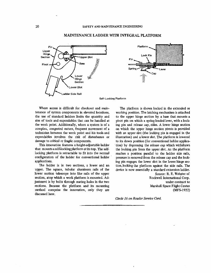
The lamp is made with two filaments supported between three posts. The primary filament connects the common post with a spring-loaded primary post. The secondary filament is mounted between the com-
Primary Filament mon post and the fned secondary post. An override is provided externally to permit manual switching from primary to secondary element.
With the external switch as shown, current flows though the common post, the primary filament, the springloaded primary post, and the switch. The pri- mary filament is on and the secondary filament is off. If the primary filament burns out, the springloaded primary post automatically makes contact with the secondary post and current flows through the com- mon post, the secondary filament, the secondary post to its contact, the primary post, and the switch. The primary filament is off and the secondary filament is on.
Should automatic switching fail, the override is switched to its opposite position and current flows
External Current through the common post, the secondary filament, - + the secondary post, and the switch. The primary fila-
In many test prop- an osciuograph printout of ment is off and the secondary filament is on. test performance is required for analysis. Because the Source: W. B. Ingle of service life of oscillograph lamps is unpredictable, Rockwell International Corp.
many tests are interrupted or nullified by lamp under contract to failures. The expense of such failures can be appre- Marshall Space Flight Center ciable where sophisticated and complex procedures (MFS-498) are involved.
A lamp with a pimary and a secondary filament, Circle 15 on Reader Service Card. with means for automatic switching to the secondary filament at primary filament burnout, overcomes the problem.
SAFETY AND MAINTENANCE ENGINEERING
ENmCE EmDER WPTH NEGWAL PLATFOM
Ladder Side Rail
Self-Locking Platform
Where access is difficult for checkout and main- tenance of system components in elevated locations, the use of standard ladders limits the quantity and size of tools and expendables that can be handled at the work point. Additionally, where a system is of a complex, congested nature, frequent movement of a technician between the work point and his tools and expendables involves the risk of disturbance or damage to critical or fragile components.
This innovation features a height-adjustable ladder that mounts a self-locking platform at its top. The self- locking platform is retractable to fit into the normal configuration of the ladder for conventional ladder '
applications. The ladder is in two sections, a lower and an
upper. The square, tubular aluminum rails of the lower section telescope into like rails of the upper section, atop which a work platform is mounted. Ad- justment is by bolts through mating holes in the two sections. Because the platform and its mounting method comprise the innovation, only they are discussed here.
The platform is shown locked in the extended or working position. The latching mechanism is attached to the upper hinge section by a base that mounts a pivot pin on which a spring loaded lever, with a lock- ing pin and release cap, rides. A lower hinge section on which the upper hinge section pivots is provided with an upper slot (the locking pin is engaged in the illustration) and a lower slot. The platform is lowered to its down position (for conventional ladder applica- tion) by depressing the release cap which withdraws the locking pin from the upper slot. As the platform reaches a position parallel to the ladder side rails, pressure is removed from the release cap and the lock- ing pin engages the lower slot in the lower hinge sec- tion,locking the platform against the side rails. The device is now essentially a standard extension ladder.
Source: R. E. Webster of Rockwell International Corp.
under contract to Marshall Space Flight Center
(PAFS-1922)
Circle 16 on Reader Service Card.
MAINTENANCE ENGINEEMNG
REPAPR TECHMQUE FOR PLASTIC PUSHB
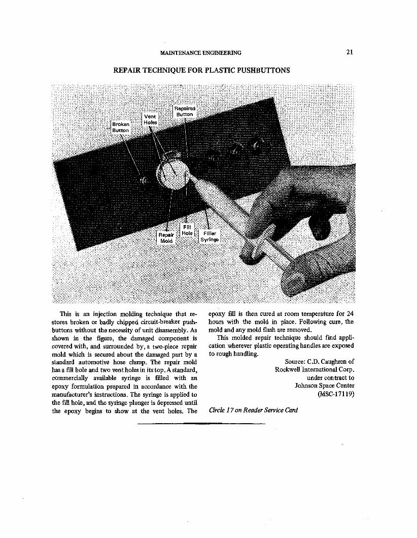
This is an injection molding technique that re- stores broken or badly chipped circuit-breaker push- buttons without the necessity of unit disassembly. As shown in the figure, the damaged component is covered with, and surrounded by, a two-piece repair mold which is secured about the damaged part by a standard automotive hose clamp. The repair mold has a fill hole and two vent holes in its top. A standard, commercially available syringe is filled with an epoxy formulation prepared in accordance with the manufacturer's instructions. The syringe is applied to the fill hole, and the syringe plunger is depressed until the epoxy begins to show at the vent holes. The
epoxy fill is then cured at room temperature for 24 hours with the mold in place. Following cure, the mold and any mold flash are removed.
This molded repair technique should find appli- cation wherever plastic operating handles are exposed to rough handling.
Source: C.D. Caughren of Rockwell International Corp.
under contract to Johnson Space Center
@SC-17119)
Circle 1 7 on Reader Service Card
SAFETY AND MAINTENANCE ENGINEERING
TV SYSTEM FOR MONITOMNG WEMOTE BULATIONS
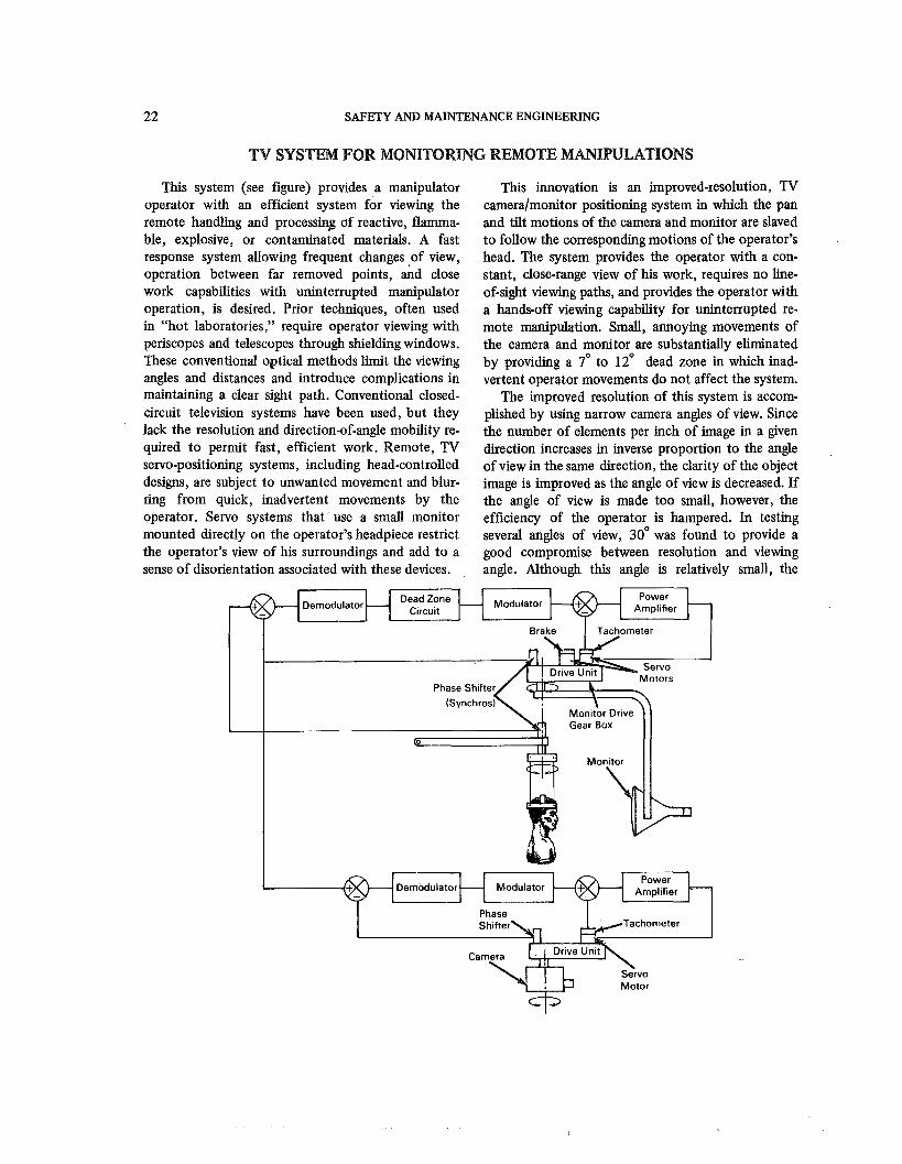
This system (see figure) provides a manipulator operator with an efficient system for viewing the remote handling and processin8 of reactive, flamma- ble, explosive, or contaminated materials. A fast response system allowing frequent changes of view, operation between far removed points, i d close work capabilities with uninterrupted manipulator operation, is desired. Prior techniques, often used in "hot laboratories," require operator viewing with periscopes and telescopes through shielding windows. These conventional optical methods limit the viewing angles and distances and introduce complications in maintaining a clear sight path. Conventional closed- circuit television systems have been used, but they lack the resolution and direction-of-angle mobility re- quired to permit fast, efficient work. Remote, TV servo-positioning systems, including head-controlled designs, are subject to unwanted movement and blur- ring from quick, inadvertent movements by the operator. Servo systems that use a small monitor mounted directly on the operator's headpiece restrict the operator's view of his surroundings and add to a sense of disorientation associated with these devices.
This innovation is an improved-resolution, TV cameralmonitor positioning system in which the pan and tilt motions of the camera and monitor are slaved to follow the corresponding motions of the operator's head. The system provides the operator with a con- stant, close-range view of his work, requires no line- of-sight viewing paths, and provides the operator with a hands-off viewing capability for uninterrupted re- mote manipulation. Small, annoying movements of the camera and monitor are substantially eliminated by providing a 7' to 1 2 O dead zone in which inad- vertent operator movements do not affect the system.
The improved resolution of this system is accom- plished by using narrow camera angles of view. Since the number of elements per inch of image in a given direction increases in inverse proportion to the angle of view in the same direction, the clarity of the object image is improved as the angle of view is decreased. If the angle of view is made too small, however, the efficiency of the operator is hampered. In testing several angles of view, 30° was found to provide a good compromise between resolution and viewing angle. Although this angle is relatively small, the
MAINTENANCE ENGIMEERING 23
operator can readily shift the view to see throughout a much larger volume.
The remote viewing system consistsof a 675-line- per-frame, 30-frame-per-second TV camera; a 14-inch monitor; an operator headpiece; and a servo coupling system. The 36cm (14-inch) slaved monitor posi- tioned about 58 cm (23 inches) from the operator's eyes provides a 30° angle of view. This results in a 1 : 1 correspondence between the viewing angles, reduces operator disorientation, and permits easy 10- cation of items within the working volume.
Small synchros coupled to an easily donned headpiece provide command signals for the pan and tilt motions of the monitor. The voltages generated by the headpiece synchros are fed through the demodulator, dead zone, and modulator circuits. They are subtracted from similar voltages generated by the synchros on the monitor drive gear boxes. The resultant voltages ultimately control the position of the monitor. The camera is similarly controlled by comparing the monitor and camera position signals. A
near 1 : 1 positional correspondence is maintained between the motions of the operator's head, the camera and the monitor.
One of the features of the head-controlled TV positioning system is that the operator can establish and maintain his viewing orientation relative to a remote worksite. After surveying the worksite area, an operator gains a sense of presence in the remote area which permits him to relocate objects and per- form work efficiently. ,Conventional television posi- tioning systems do not have this characteristic and consequently operators have no way of knowing in which direction the camera is aimed until they some- how relate the position of the camera with the scene being viewed.
Source: R. Goertz, C. Potts, D. Mingesz, and J. Liidberg
Argonne National Laboratory (ARG-128)
Circle 18 on Reader Service Card.
LmDER HOLDER FOR TANK M m T E N M C E
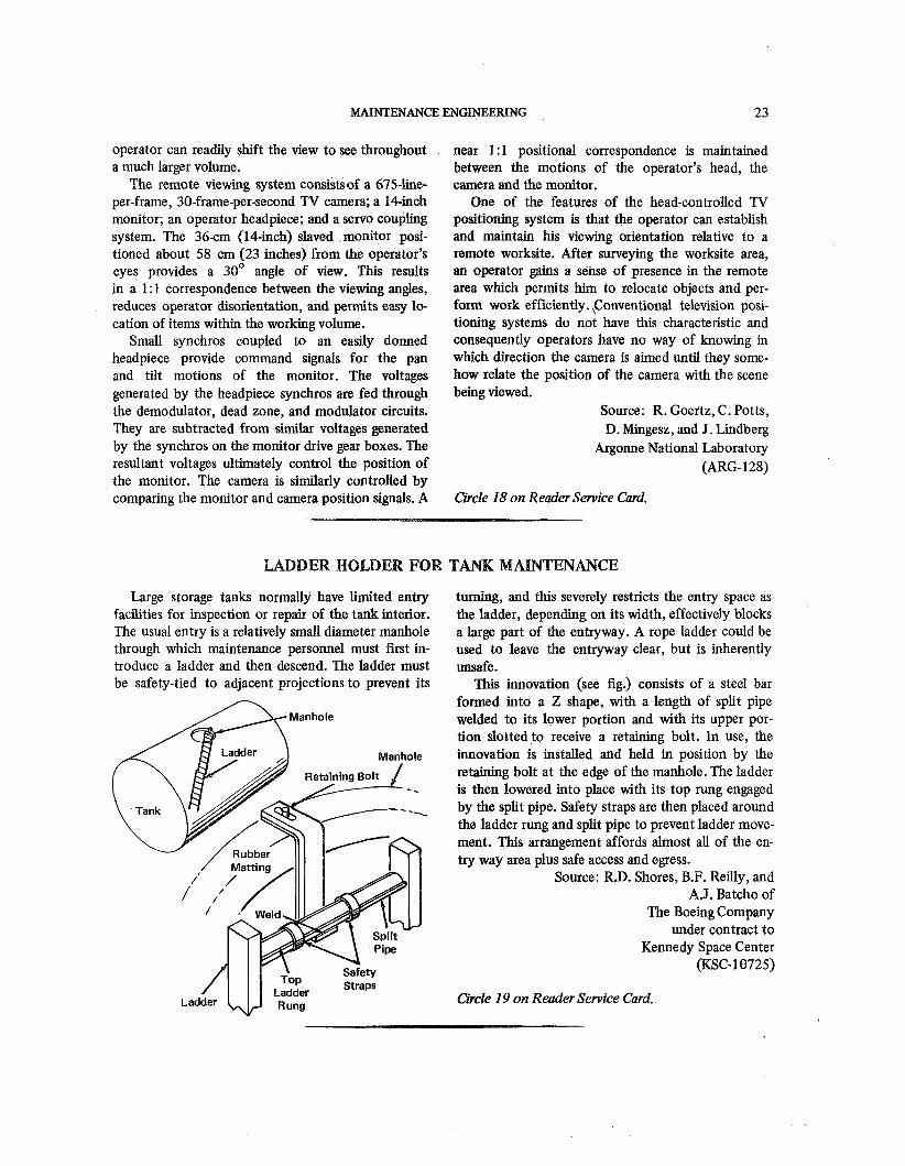
Large storage tanks normally have limited entry turning, and this severely restricts the entry space as facilities for inspection or repair of the tank interior. the ladder, depending on its width, effectively blocks The usual entry is a relatively small diameter manhole a large part of the entryway. A rope ladder could be through which maintenance personnel must first in- used to leave the entryway clear, but is inherently troduce a ladder and then descend. The ladder must unsafe. be safety-tied to adjacent projections to prevent its This innovation (see fig.) consists of a steel bar
formed into a Z shape, with a length of split pipe welded to its lower portion and with its upper por- tion slotted to receive a retaining bolt. In use, the innovation is installed and held in position by the retaining bolt at the edge of the manhole. The ladder
- - is then lowered into place with its top rung engaged by the split pipe. Safety straps are then placed around the ladder rung and split pipe to prevent ladder move- ment. This arrangement affords almost all of the en- try way area plus safe access and egress.
Source: R.D. Shores, B.F. Reilly, and A.J. Batcho of
The Boeing Company under contract to
Kennedy Space Center (KSC-18725)
Circle 19 on Reader Service Card.
24 SAFETY AND MAINTENANCE ENGINEERING
DEVICE DETECTS SUBMERGED LEAKS
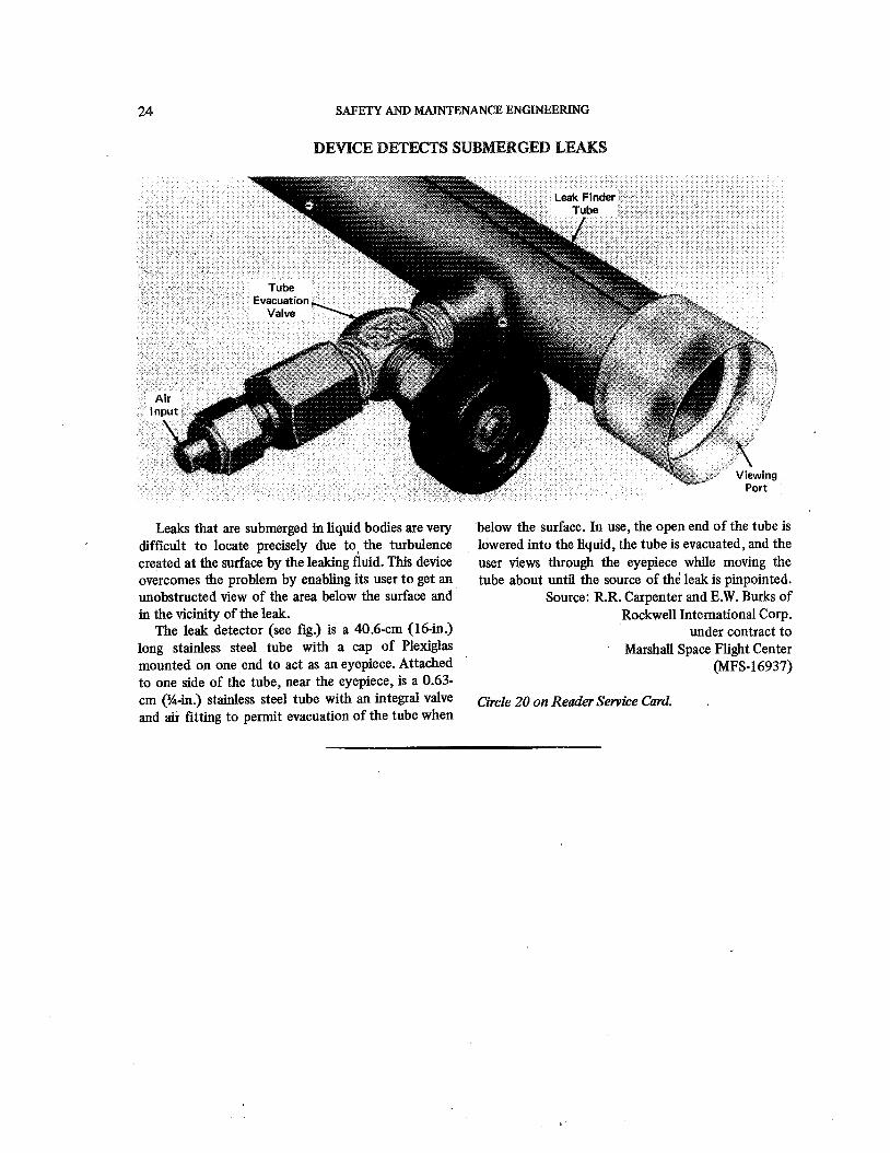
Leaks that are submerged in liquid bodies are very difficult to locate precisely due to, the turbulence created at the surface by the leaking fluid. This device overcomes the problem by enabling its user to get an unobstructed view of the area below the surface and in the vicinity of the leak.
The leak detector (see fig.) is a 40.6-cm (16-in.) long stainless steel tube with a cap of Plexiglas mounted on one end to act as an eyepiece. Attached
~
to one side of the tube, near the eyepiece, is a 0.63- cm (%-in.) stainless steel tube with an integral valve and air fitting to permit evacuation of the tube when
below the surface. In use, the open end of the tube is lowered into the liquid, the tube is evacuated, and the user views through the eyepiece while moving the tube about until the source of the leak is pinpointed.
Source: R.R. Carpenter and E.W. Burks of Rockwell International Corp.
under contract to Marshall Space Flight Center
(MFS- 16937)
Circle 20 on Reader Service Card. ,
Patent Information
The following innovations, described in this Compilation, have been patented or are being considered for patent action as indicated below:
Improved Protective Helmet Assembly (Page 2) MSC-187 This invention has been patented by NASA (U.S. Patent No. 3,502,074). Inquiries
concerning nonexclusive or exclusive license for its commercial development should be addressed to:
Patent Counsel Johnson Space Center Code AM Houston, Texas 77058
Self-Breaking Device for Escape Cable (Page 6) KSC-664 This invention has been patented by NASA (U.S. Patent No. 3,568,795). Inquiries
concerning nonexclusive or exclusive license for its commercial development should be addressed to:
Patent Counsel Kennedy Space Center Code AD-PAT Kennedy Space Center, Florida 32899
Vibration Reduced by Post-Stressing of Concrete (Page 14) ARG-130 This is the invention of an AEC employee, and U.S. Patent No. 3,O 15 9 12 has been
issued to him. Inquiries concerning license for its commercial development may be addressed to the inventor: Mr. S. H. Fistedis, Reactor Analysis And Safety Division, Argonne National Laboratory, 9700 South Cass Avenue, Argonne, Illinois 60439.
Remote Handling Device for Hazardous Materials (Page 15) LAR-10634) This invention is owned by NASA, and a patent application has been filed.
Inquiries concerning nohexclusive or exclusive liscense for its development should be addressed to:
Patent Counsel Langley Research Center Code 456 Hampton, V i w a 23365
SAFETY AND MAINTENANCE ENGINEERING
Remote Manipulation in High Vacuum Using Mlaster/Slave Manipulators (Page 16) LAR-10673
Inquiries concerning rights for the commercial use of this invention should be addressed to:
Patent Counsel Langley Research Center Code 456 Harnpton, Virginia 23365
Improved Fire-Resistant Coatings (Page 17) GSC - 10072 This invention has been patented by NASA (U.S. Patent No. 3,493,401). Inquiries
concerning nonexclusive or exclusive license for its commercial development should be addressed to :
Patent Counsel Goddard Space Flight Center Code 204 Greenbelt, Maryland 2077 1
Oscillation Damper for Tall Structures (Page 18) LAR-10193 This invention has been patented by NASA (U.S. Patent No. 3,015912). Inquiries
concerning nonexclusive or exclusive license for its commercial development should be addressed to:
Patent Counsel Langley Research Center Code 456 Hampton, Virginia 23365

Notes:

Notes:
NATIONAL AERONAUTICS AND SPACE ADMINISTRATION WASHINGTON, D.C. 20546 POSTAGE A N D FEES P A I D
N A T I O N A L AERONAUTICS A N D
OFFICIAL BUSINESS SPACE ADM l NISTRATION
PENALTY FOR PRIVATE USE 1300 SPECiAL FOURTH-CLASS RATE As( Q I us.MAIL
BOOK
, . : If Undeliverable (Section 168
Postal Manual) Do Not Return
"The aermautical and space activities of the United, Strites shall be condttcted so as to contribute . . . to the exparzsion of h~rttzan knowl- edge of phenotjzena in the at~tzosphere and space. The Adrjzinistration shall provide for the widest practicable and appropriate dissenti~ation of irzforrtlntion cortcerning its activities a d the resnlts thereof!'
-NATIONAL AERONAUTICS AND SPACE ACT OF 1958
NASA TECHN Y UTILIZATION PUBLICATIONS These describe science or technology derived from NASA's activities that may be of particirlar interest in commercial and other non-aerospace applications. Piiblications include:
TECH BRIEFS: Single-page descriptions of individual innovations, devices, methods, or concepts.
TECHNOLOGY SURVEYS: Selected surveys of NASA contributions to entire areas of technology.
OTHER TU PUBLICATIONS: These include handbooks, reports, conference proceedings, special studies, and selected bibliographies.
Details on the availability o! these publicatlons may be obtafned from:
National Aeronautics a d
Space Administration Code KT Washington, D.C. 20546
Technology Utilization piiblications are part
of NASA's formal series of scientific and
technical p~iblications. Others incli~de Tech-
nical Reports, Technical Notes, Technical
Memorandums, Contractor Reports, Technical
Translations, and Special Publications.
Details on their availability may be obtained fiom:
National Aeronautics and
Space Administration
Code KS Washington, D.C. 20546
NATIONAL AERONAUTICS AND SPACE i4DMINISTRATIBN Washington, D,C. PO546