Embed Size (px)
Citation preview

Control4® Wireless Thermostat by Aprilaire®
Safety and Installation Guide
ii
Control4 disclaimer
Control4® makes no representations or warranties with respect to this publication, and specifically disclaims any express or implied warranties of merchantability or fitness for any particular purpose. Control4 reserves the right to make changes to any and all parts of this publication at any time, without any obligation to notify any person or entity of such changes.
Copyright and trademarks
Copyright ©2015, Control4 Corporation. All rights reserved. Control4, the Control4 logo, the 4-ball logo, 4Store, 4Sight, Control My Home, Everyday Easy, and Mockupancy are registered trademarks or trademarks of Control4 Corporation in the United States and/or other countries. All other names and brands may be claimed as the property of their respective owners. All specifications subject to change without notice.
No part of this publication may be reproduced, photocopied, stored on a retrieval system, or transmitted without the express written consent of the publisher.
Warranty
For complete warranty information, including details on consumer legal rights as well as warranty exclusions, visit www.control4.com/warranty.
Contact information
Control4 Corporation 11734 S. Election Road Salt Lake City, UT 84020 USA www.control4.com
Control4 Wireless Thermostat by Aprilaire Safety and Installation Guide Part Number: 61001048, 3/12/2015 Model Number: C4-THERM
Legal notices
GNU GNU GENERAL PUBLIC LICENSE TERMS AND CONDITIONS FOR COPYING, DISTRIBUTION AND MODIFICATION (Section 3.b.)
You may copy and distribute the Program (or a work based on it, under Section 2) in object code or executable form under the terms of Sections 1 and 2 provided that you also do one of the following:
Accompany it with a written offer, valid for at least three years, to give any third party, for a charge no more than your cost of physically performing source distribution, a complete machine-readable copy of the corresponding source code, to be distributed under the terms of Sections 1 and 2 on a medium customarily used for software interchange.
The complete text for this license is available on the Control4 web site at: www.control4.com.
Gracenote Gracenote®, Gracenote logo and logotype, and the “Powered by Gracenote” logo are either a registered trademark or a trademark of Gracenote, Inc. in the United States and/or other countries. Music and DVD recognition technology and related data are provided by Gracenote®. Gracenote is the industry standard in Music and DVD recognition technology and related content delivery. For more information visit www.gracenote.com.
MPEG Fraunhofer IIS and Thomson. MPEG Layer-3 audio coding technology licensed from Fraunhofer IIS and Thomson. Supply of this product does not convey a license nor imply any right to distribute content created with this product in revenue-generating broadcast systems (terrestrial, satellite, cable, and /or other distribution channels), streaming applications (via Internet, intranets, and/or other networks), other content distribution systems (pay-audio or audio-on-demand applications, and the like) or on physical media (compact discs, digital versatile discs, semiconductor chips, hard drives, memory cards, and the like). An independent license for such use is required. For details, visit mp3licensing.com. Radio Locator is the service provider of AM/FM channel list.
Spread This product uses software developed by Spread Concepts LLC for use in the Spread toolkit. For more information about Spread see www.spread.org.
All Media Guide © 2005-2008 All Media Guide, LLC provides music and video recognition technology that provides cover art and related text that enriches the Control4 user Navigators.
iii
ContentsSupported model . . . . . . . . . . . . . . . . . . . . . . . . . . . . . . . . . . . . . . . . . . . . . . . . . . . . . . . . . . 1Important safety instructions . . . . . . . . . . . . . . . . . . . . . . . . . . . . . . . . . . . . . . . . . . . . . . . 1General description . . . . . . . . . . . . . . . . . . . . . . . . . . . . . . . . . . . . . . . . . . . . . . . . . . . . . . . 2Box contents . . . . . . . . . . . . . . . . . . . . . . . . . . . . . . . . . . . . . . . . . . . . . . . . . . . . . . . . . . . . . 3Supported systems . . . . . . . . . . . . . . . . . . . . . . . . . . . . . . . . . . . . . . . . . . . . . . . . . . . . . . . 3Installation . . . . . . . . . . . . . . . . . . . . . . . . . . . . . . . . . . . . . . . . . . . . . . . . . . . . . . . . . . . . . . . 4
Installation location recommendations . . . . . . . . . . . . . . . . . . . . . . . . . . . . . . . . . . . . 4If replacing an existing thermostat . . . . . . . . . . . . . . . . . . . . . . . . . . . . . . . . . . . . . . . . 5Thermostat mounting . . . . . . . . . . . . . . . . . . . . . . . . . . . . . . . . . . . . . . . . . . . . . . . . . . . 6Wiring terminal . . . . . . . . . . . . . . . . . . . . . . . . . . . . . . . . . . . . . . . . . . . . . . . . . . . . . . . . . 7Outdoor temperature sensor (included) . . . . . . . . . . . . . . . . . . . . . . . . . . . . . . . . . . . 9Remote temperature sensor (optional) . . . . . . . . . . . . . . . . . . . . . . . . . . . . . . . . . . . . 11Wiring diagrams . . . . . . . . . . . . . . . . . . . . . . . . . . . . . . . . . . . . . . . . . . . . . . . . . . . . . . . . 13
Conventional heat/cool single transformer . . . . . . . . . . . . . . . . . . . . . . . . . . . 13Conventional heat/cool two transformers . . . . . . . . . . . . . . . . . . . . . . . . . . . . 13Heat pump single transformer . . . . . . . . . . . . . . . . . . . . . . . . . . . . . . . . . . . . . .14Heat pump two transformers . . . . . . . . . . . . . . . . . . . . . . . . . . . . . . . . . . . . . . .14Indoor Air Quality equipment—dehumidifier . . . . . . . . . . . . . . . . . . . . . . . . . . 15Indoor Air Quality equipment—humidifier . . . . . . . . . . . . . . . . . . . . . . . . . . . . 15Indoor Air Quality equipment—ventilation . . . . . . . . . . . . . . . . . . . . . . . . . . . .16
Power and battery replacement . . . . . . . . . . . . . . . . . . . . . . . . . . . . . . . . . . . . . . . . . . 17
iv
Setup and testing . . . . . . . . . . . . . . . . . . . . . . . . . . . . . . . . . . . . . . . . . . . . . . . . . . . . . . . .18Equipment Type selection switch . . . . . . . . . . . . . . . . . . . . . . . . . . . . . . . . . . . . . . . . . 18Installer Setup menu . . . . . . . . . . . . . . . . . . . . . . . . . . . . . . . . . . . . . . . . . . . . . . . . . . . . .19Change system settings . . . . . . . . . . . . . . . . . . . . . . . . . . . . . . . . . . . . . . . . . . . . . . . . . 20HVAC Installer system settings table . . . . . . . . . . . . . . . . . . . . . . . . . . . . . . . . . . .21-25Indoor Air Quality system settings tables . . . . . . . . . . . . . . . . . . . . . . . . . . . . . . . . . 26
Air cleaning system settings table . . . . . . . . . . . . . . . . . . . . . . . . . . . . . . . . . . 26Humidifier system settings table . . . . . . . . . . . . . . . . . . . . . . . . . . . . . . . . 27-28Dehumidifier system settings table . . . . . . . . . . . . . . . . . . . . . . . . . . . . . . . . . 29Ventilation system settings table . . . . . . . . . . . . . . . . . . . . . . . . . . . . . . . . 30-32
Climate map for ASHRAE Fresh Air Setup . . . . . . . . . . . . . . . . . . . . . . . . . . . . . . . . 33Managing the ZigBee® network connection . . . . . . . . . . . . . . . . . . . . . . . . . . . . . . . 34System Test menu . . . . . . . . . . . . . . . . . . . . . . . . . . . . . . . . . . . . . . . . . . . . . . . . . . . . . . 35 System Test tables . . . . . . . . . . . . . . . . . . . . . . . . . . . . . . . . . . . . . . . . . . . . . . . . . . 38-42
Quick reference to controls and display . . . . . . . . . . . . . . . . . . . . . . . . . . . . . . . . . . . . 43Troubleshooting . . . . . . . . . . . . . . . . . . . . . . . . . . . . . . . . . . . . . . . . . . . . . . . . . . . . . . . . . 44Error codes . . . . . . . . . . . . . . . . . . . . . . . . . . . . . . . . . . . . . . . . . . . . . . . . . . . . . . . . . . . . . 47Thermostat features . . . . . . . . . . . . . . . . . . . . . . . . . . . . . . . . . . . . . . . . . . . . . . . . . . . . . 48Specifications . . . . . . . . . . . . . . . . . . . . . . . . . . . . . . . . . . . . . . . . . . . . . . . . . . . . . . . . . . . 49
1
Supported model
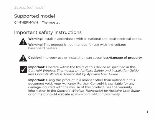
Supported modelC4-THERM-WH Thermostat
Important safety instructionsWarning! Install in accordance with all national and local electrical codes.
Warning! This product is not intended for use with line-voltage baseboard heaters.
Caution! Improper use or installation can cause loss/damage of property.
Important: Operate within the limits of this device as specified in this Control4 Wireless Thermostat by Aprilaire Safety and Installation Guide and Control4 Wireless Thermostat by Aprilaire User Guide.
Important: Using this product in a manner other than outlined in this document voids your warranty. Further, Control4 is not liable for any damage incurred with the misuse of this product. See the warranty information in the Control4 Wireless Thermostat by Aprilaire User Guide or on the Control4 website at www.control4.com/warranty.
2
General description
General descriptionThis Control4® Thermostat enables intelligent HVAC and Indoor Air Quality control as part of a Control4 automated system. This thermostat uses the ZigBee® (802.15.4) wireless networking standard to communicate with the Control4 system.
The Control4 Thermostat features a backlit LCD that displays the temperature, HVAC status, Indoor Air Quality control status, fan status, hold status, and HVAC operating mode. The home screen allows temperature setpoint adjustments, HVAC mode change, various hold options, fan control, and access to the Indoor Air Quality control screens. The Indoor Air Quality control screens can be used to control ventilation, humidification, or dehumidification. The thermostat can operate as a stand-alone control if it loses communication with the Control4 system.
3
Box contents• Thermostat• Wired outdoor temperature sensor• 4 AA batteries• 4 screws• 4 wall anchors• Warranty card• Control4 Wireless Thermostat by
Aprilaire Safety and Installation Guide (this document)
Supported systems• One- or two-stage conventional
heat/cool system• One- or two-stage heat pump with
up to two stages of auxiliary or emergency heat
• Optional heat-only or cool-only operation
• Configurable for electric or fossil fuel heating
• Millivolt heat• Hydronic heat
Box contents
4
Installation
InstallationInstallation location recommendations
Thermostat should be mounted:
• On an interior wall, in a frequently occupied space.• Approximately 5' (about 1.5 meters) above the floor.• At least 18" (about 0.5 meter) from an outside wall.• Thermostat can be mounted to a vertical, single gang, electrical junction box.
Do not mount thermostat:
• Behind doors, in corners, or other dead air spaces.• In direct sunlight, near lighting fixtures, or other appliances that give off heat.• On an outside or unconditioned area wall.• In the flow of a supply register, in stairwells, or near outside doors.• On a wall with concealed pipes or ductwork.
5
If replacing an existing thermostat• If your existing thermostat is configured using system settings, record the
existing system settings so they can be referenced when setting the HVAC Installer system settings for this thermostat. For detailed instructions on how to access and read the system settings for your existing thermostat, refer to the installation instructions for that thermostat.
• Turn off power to the thermostat.• Remove the thermostat from the wall, but do not disconnect the wires yet.• Check the number of wires attached to the existing thermostat. Wrap the bare
ends of any unused wires in electrical tape to prevent them from shorting to other wires.
• If the existing thermostat has a letter identifying each wire, use a piece of tape to label each wire with the corresponding letter. The labels can be used to later identify the wires for your new thermostat.
• Disconnect the wires from the existing thermostat, taking care that none of the wires fall back into the wall.
6
Installation
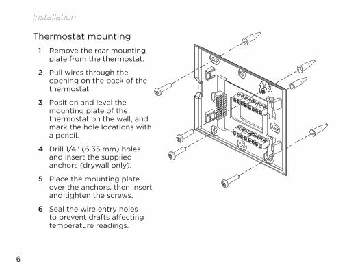
Thermostat mounting1 Remove the rear mounting
plate from the thermostat.
2 Pull wires through the opening on the back of the thermostat.
3 Position and level the mounting plate of the thermostat on the wall, and mark the hole locations with a pencil.
4 Drill 1/4" (6.35 mm) holes and insert the supplied anchors (drywall only).
5 Place the mounting plate over the anchors, then insert and tighten the screws.
6 Seal the wire entry holes to prevent drafts affecting temperature readings.
7
Wiring terminal
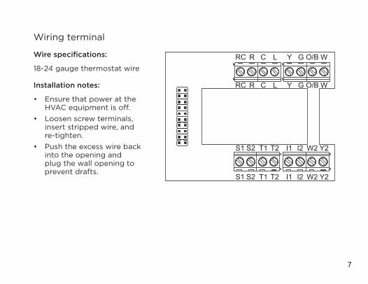
Wire specifications:
18-24 gauge thermostat wire
Installation notes:
• Ensure that power at the HVAC equipment is off.
• Loosen screw terminals, insert stripped wire, and re-tighten.
• Push the excess wire back into the opening and plug the wall opening to prevent drafts.
Y2I1 W2S2S1 T1 T2 I2
GY O/B WRC R LC
GY O/B WRC R LC
Y2I1 W2S2S1 T1 T2 I2
8
Installation
I1 & I2—Indoor Air Quality control output
C—Common (optional when powered by batteries)
O/B—Reversing valve
Y—First-stage cooling / compressor
Y2—Second-stage cooling / compressor
G—Fan
RC—24VAC supply cooling1
R—24VAC supply heating1
W2—Second-stage heat / auxiliary
W—First-stage heat / auxiliary
L—System fault indicator (optional) (heat pump only)
S1 & S2—Outdoor temperature sensor (included)
T1 & T2—Remote temperature sensor (optional)1 Jumper between RC & R is used in single-transformer systems (see wiring diagrams).
9
Outdoor temperature sensor (included)Outdoor temperature can be measured by attaching the included sensor to the S1 and S2 terminals. The outdoor sensor must be enabled in the thermostat’s Installer Setup menu.
Heat pump models can use the outdoor temperature to effectively utilize the heat pump:
• When the outdoor temperature is less than the Low Balance Point, the heat pump is locked out and only auxiliary heating is used.
• When the outdoor temperature is higher than the High Balance Point, the auxiliary heating is locked out and only the heat pump is used to provide heating.
Indoor Air Quality functions can use the outdoor temperature sensor to:
• Control humidification setpoint based on outdoor temperature to prevent condensation.
• Lock out humidification for temperatures over 60°F (15.6°C) or below -30°F (-34.4°C).
• Lock out ventilation based on high and/or low outdoor temperatures.
10
Installation
Y2I1 W2S2S1 T1 T2 I2
GY O/B WRC R LC
GY O/B WRC R LC
Y2I1 W2S2S1 T1 T2 I2
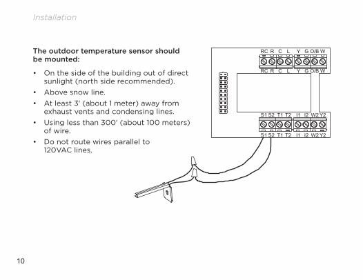
The outdoor temperature sensor should be mounted:
• On the side of the building out of direct sunlight (north side recommended).
• Above snow line.• At least 3' (about 1 meter) away from
exhaust vents and condensing lines.• Using less than 300' (about 100 meters)
of wire.• Do not route wires parallel to
120VAC lines.
11
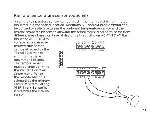
A remote temperature sensor can be used if the thermostat is going to be mounted in a concealed location. Additionally, Control4 programming can be utilized to switch between the on-board temperature sensor and the remote temperature sensor, allowing the temperature reading to come from different areas based on time of day or daily activity. An AC-FMTS1-W flush mount or AC-DOTS1-W surface mount remote temperature sensor can be attached to the T1 and T2 terminals and mounted in a recommended area. The remote sensor must be enabled in the thermostat’s Installer Setup menu. When the remote sensor is selected as the primary sensor (System Setting 14 [Primary Sensor]), it overrides the internal sensor.
Y2I1 W2S2S1 T1 T2 I2
GY O/B WRC R LC
GY O/B WRC R LC
Y2I1 W2S2S1 T1 T2 I2
Remote temperature sensor (optional)
12
Installation
The remote temperature sensor should be mounted:
• On an interior wall, in a frequently occupied space.• About 5' (1.5 meters) above the floor.• At least 18" (about 0.5 meter) from an outside wall.• Using less than 300' (about 100 meters) of wire.
Do not mount the remote sensor:
• Behind doors, in corners, or other dead air spaces.• In direct sunlight, near lighting fixtures, or near other appliances that give off heat.• On an outside or unconditioned area wall.• In the flow of a supply register, in stairwells, or near outside doors.• On a wall with concealed pipes or ductwork. • Parallel to 120VAC lines.
13
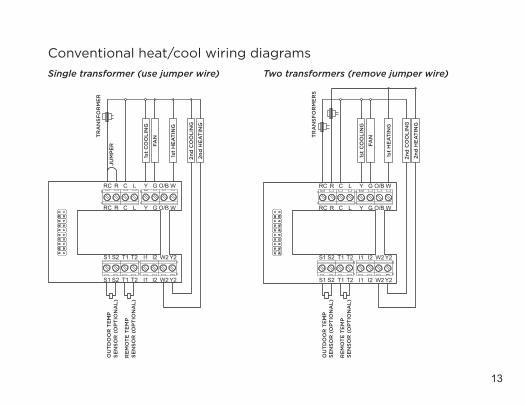
Conventional heat/cool wiring diagramsSingle transformer (use jumper wire) Two transformers (remove jumper wire)
Y2I1 W2S2S1 T1 T2 I2
GY O/B WRC R LC
GY O/B WRC R LC
Y2I1 W2S2S1 T1 T2 I2
JUM
PE
RO
UT
DO
OR
TE
MP
SE
NSO
R (
OP
TIO
NA
L)
RE
MO
TE
TE
MP
SE
NSO
R (
OP
TIO
NA
L)
TR
AN
SFO
RM
ER
1st
HE
AT
ING
FAN
2nd
CO
OLI
NG
1st
CO
OLI
NG
2nd
HE
AT
ING
Y2I1 W2S2S1 T1 T2 I2
GY O/B WRC R LC
GY O/B WRC R LC
Y2I1 W2S2S1 T1 T2 I2
OU
TD
OO
R T
EM
P
SEN
SOR
(O
PT
ION
AL)
RE
MO
TE
TE
MP
SE
NSO
R (
OP
TIO
NA
L)
TR
AN
SFO
RM
ER
S
1st
HE
AT
ING
FAN
2nd
CO
OLI
NG
1st
CO
OLI
NG
2nd
HE
AT
ING
14
Installation
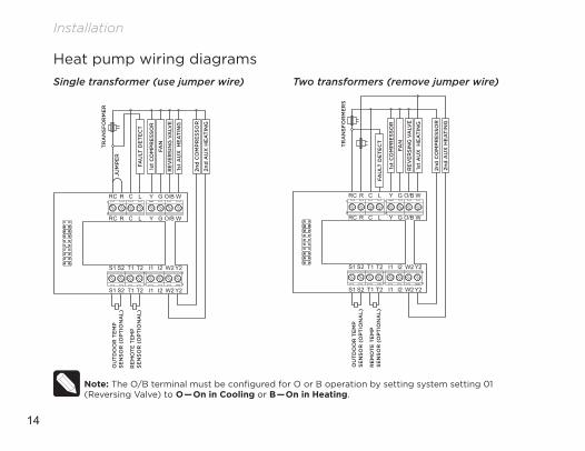
Heat pump wiring diagramsSingle transformer (use jumper wire) Two transformers (remove jumper wire)
Y2I1 W2S2S1 T1 T2 I2
GY O/B WRC R LC
GY O/B WRC R LC
Y2I1 W2S2S1 T1 T2 I2
JUM
PE
RO
UT
DO
OR
TE
MP
SE
NSO
R (
OP
TIO
NA
L)
RE
MO
TE
TE
MP
SE
NSO
R (
OP
TIO
NA
L)
TR
AN
SFO
RM
ER
1st
AU
X H
EA
TIN
G
FAN
2nd
CO
MP
RE
SSO
R
1st
CO
MP
RE
SSO
R
2nd
AU
X H
EA
TIN
G
FAU
LT D
ET
EC
T
RE
VE
RSI
NG
VA
LVE
Y2I1 W2S2S1 T1 T2 I2
GY O/B WRC R LC
GY O/B WRC R LC
Y2I1 W2S2S1 T1 T2 I2
OU
TD
OO
R T
EM
P
SEN
SOR
(O
PT
ION
AL)
RE
MO
TE
TE
MP
SE
NSO
R (
OP
TIO
NA
L)
TR
AN
SFO
RM
ER
S
FAU
LT D
ET
EC
T
1st
AU
X H
EA
TIN
G
FAN
2nd
CO
MP
RE
SSO
R
1st
CO
MP
RE
SSO
R
2nd
AU
X H
EA
TIN
G
RE
VE
RSI
NG
VA
LVE
Note: The O/B terminal must be configured for O or B operation by setting system setting 01 (Reversing Valve) to O—On in Cooling or B—On in Heating.
15
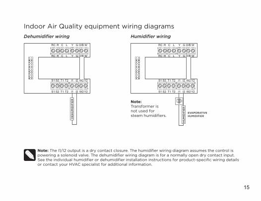
Indoor Air Quality equipment wiring diagramsDehumidifier wiring Humidifier wiring
Y2I1 W2S2S1 T1 T2 I2
GY O/B WRC R LC
GY O/B WRC R LC
Y2I1 W2S2S1 T1 T2 I2
DE
HU
MID
IFIE
R
Y2I1 W2S2S1 T1 T2 I2
GY O/B WRC R LC
GY O/B WRC R LC
Y2I1 W2S2S1 T1 T2 I2
HU
MID
IFIE
R
EVAPORATIVEHUMIDIFIER
Note: Transformer is not used for steam humidifiers.
Note: The I1/I2 output is a dry contact closure. The humidifier wiring diagram assumes the control is powering a solenoid valve. The dehumidifier wiring diagram is for a normally open dry contact input. See the individual humidifier or dehumidifier installation instructions for product-specific wiring details or contact your HVAC specialist for additional information.
16
Installation
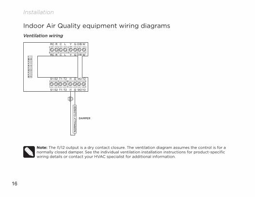
Indoor Air Quality equipment wiring diagramsVentilation wiring
Note: The I1/I2 output is a dry contact closure. The ventilation diagram assumes the control is for a normally closed damper. See the individual ventilation installation instructions for product-specific wiring details or contact your HVAC specialist for additional information.
Y2I1 W2S2S1 T1 T2 I2
GY O/B WRC R LC
GY O/B WRC R LC
Y2I1 W2S2S1 T1 T2 I2
DAMPER
NO
RM
ALL
Y C
LOSE
D
17
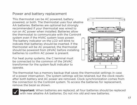
Power and battery replacementThis thermostat can be AC powered, battery powered, or both. The thermostat uses four alkaline AA batteries. Batteries are optional but strongly recommended if your thermostat was wired to run on AC power when installed. Batteries allow the thermostat to communicate with the Control4 system even if the HVAC system loses power. The battery indicator on the LCD will blink to indicate that batteries should be inserted. If the thermostat will be AC powered, the thermostat should be powered from 24VAC before installing batteries to confirm AC power is present.
For heat pump systems, the C terminal must be connected to the common of the 24VAC transformer for the system fault indicator to operate.
The thermostat has a memory backup that saves the thermostat settings in case of a power interruption. The system settings will be retained, but the clock resets after both battery and AC power are removed. Clock synchronization comes from the connection to the Control4 system. To access the batteries for replacement, remove the bezel as shown.
Important: When batteries are replaced, all four batteries should be replaced with new alkaline AA batteries. Do not mix old and new batteries.
18
Setup and testing
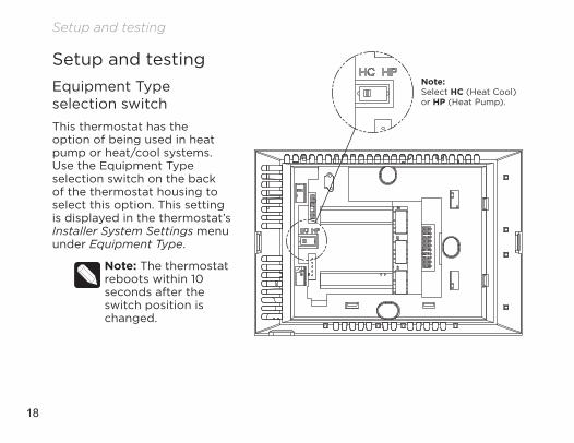
Setup and testingEquipment Type selection switchThis thermostat has the option of being used in heat pump or heat/cool systems. Use the Equipment Type selection switch on the back of the thermostat housing to select this option. This setting is displayed in the thermostat’s Installer System Settings menu under Equipment Type.
Note: The thermostat reboots within 10 seconds after the switch position is changed.
Note: Select HC (Heat Cool) or HP (Heat Pump).
19
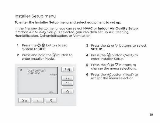
Installer Setup menuTo enter the Installer Setup menu and select equipment to set up:
In the Installer Setup menu, you can select HVAC or Indoor Air Quality Setup. If Indoor Air Quality Setup is selected, you can then set up Air Cleaning, Humidification, Dehumidification, or Ventilation.
1 Press the button to set system to OFF.
2 Press and hold the button to enter Installer Mode.
3 Press the or buttons to select SETUP.
4 Press the button (Next) to enter Installer Setup.
5 Press the or buttons to change the menu selections.
6 Press the button (Next) to accept the menu selection.
20
Setup and testing
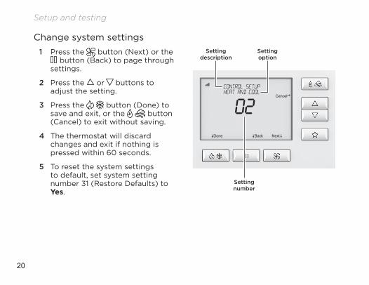
Change system settings1 Press the button (Next) or the
button (Back) to page through settings.
2 Press the or buttons to adjust the setting.
3 Press the button (Done) to save and exit, or the button (Cancel) to exit without saving.
4 The thermostat will discard changes and exit if nothing is pressed within 60 seconds.
5 To reset the system settings to default, set system setting number 31 (Restore Defaults) to Yes.
Setting number
Setting description
Setting option
21
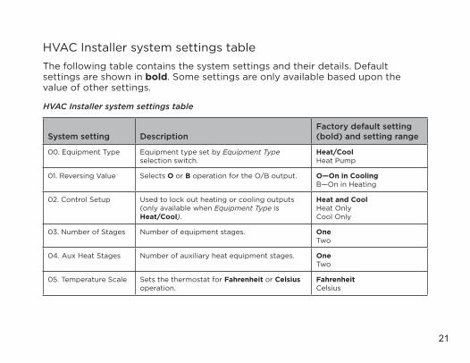
HVAC Installer system settings tableThe following table contains the system settings and their details. Default settings are shown in bold. Some settings are only available based upon the value of other settings.
HVAC Installer system settings table
System setting DescriptionFactory default setting (bold) and setting range
00. Equipment Type Equipment type set by Equipment Type selection switch.
Heat/CoolHeat Pump
01. Reversing Value Selects O or B operation for the O/B output. O—On in CoolingB—On in Heating
02. Control Setup Used to lock out heating or cooling outputs (only available when Equipment Type is Heat/Cool).
Heat and CoolHeat OnlyCool Only
03. Number of Stages Number of equipment stages. OneTwo
04. Aux Heat Stages Number of auxiliary heat equipment stages. OneTwo
05. Temperature Scale Sets the thermostat for Fahrenheit or Celsius operation.
FahrenheitCelsius
22
Setup and testing
HVAC Installer system settings table
System setting DescriptionFactory default setting (bold) and setting range
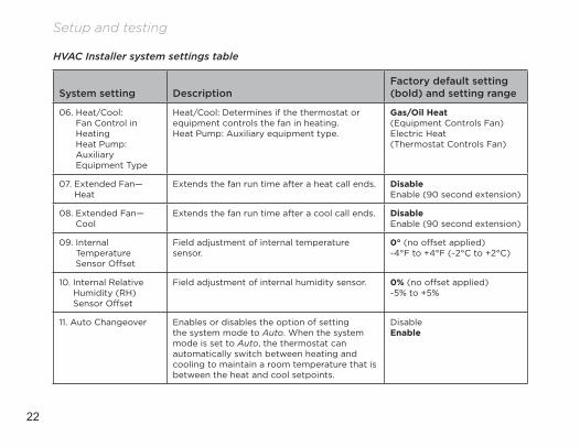
06. Heat/Cool: Fan Control in Heating Heat Pump: Auxiliary Equipment Type
Heat/Cool: Determines if the thermostat or equipment controls the fan in heating.Heat Pump: Auxiliary equipment type.
Gas/Oil Heat (Equipment Controls Fan)Electric Heat (Thermostat Controls Fan)
07. Extended Fan—Heat
Extends the fan run time after a heat call ends. DisableEnable (90 second extension)
08. Extended Fan—Cool
Extends the fan run time after a cool call ends. DisableEnable (90 second extension)
09. Internal Temperature Sensor Offset
Field adjustment of internal temperature sensor.
0° (no offset applied)-4°F to +4°F (-2°C to +2°C)
10. Internal Relative Humidity (RH) Sensor Offset
Field adjustment of internal humidity sensor. 0% (no offset applied)-5% to +5%
11. Auto Changeover Enables or disables the option of setting the system mode to Auto. When the system mode is set to Auto, the thermostat can automatically switch between heating and cooling to maintain a room temperature that is between the heat and cool setpoints.
Disable Enable
23
HVAC Installer system settings table
System setting DescriptionFactory default setting (bold) and setting range
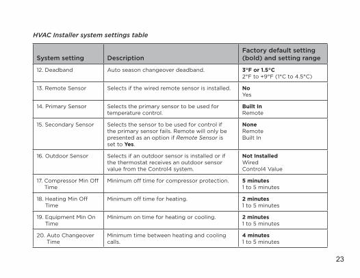
12. Deadband Auto season changeover deadband. 3°F or 1.5°C 2°F to +9°F (1°C to 4.5°C)
13. Remote Sensor Selects if the wired remote sensor is installed. NoYes
14. Primary Sensor Selects the primary sensor to be used for temperature control.
Built InRemote
15. Secondary Sensor Selects the sensor to be used for control if the primary sensor fails. Remote will only be presented as an option if Remote Sensor is set to Yes.
NoneRemoteBuilt In
16. Outdoor Sensor Selects if an outdoor sensor is installed or if the thermostat receives an outdoor sensor value from the Control4 system.
Not InstalledWiredControl4 Value
17. Compressor Min Off Time
Minimum off time for compressor protection. 5 minutes1 to 5 minutes
18. Heating Min Off Time
Minimum off time for heating. 2 minutes1 to 5 minutes
19. Equipment Min On Time
Minimum on time for heating or cooling. 2 minutes1 to 5 minutes
20. Auto Changeover Time
Minimum time between heating and cooling calls.
4 minutes1 to 5 minutes
24
Setup and testing
HVAC Installer system settings table
System setting DescriptionFactory default setting (bold) and setting range
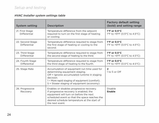
21. First Stage Differential
Temperature difference from the setpoint required to turn on the first stage of heating or cooling.
1°F or 0.5°C 1°F to +9°F (0.5°C to 4.5°C)
22. Second Stage Differential
Temperature difference required to stage from the first stage of heating or cooling to the second.
1°F or 0.5°C 1°F to +9°F (0.5°C to 4.5°C)
23. Third Stage Differential
Temperature difference required to stage from the second stage of heating to the third.
1°F or 0.5°C 1°F to +9°F (0.5°C to 4.5°C)
24. Fourth Stage Differential
Temperature difference required to stage from the third stage of heating to the fourth.
1°F or 0.5°C 1°F to +9°F (0.5°C to 4.5°C)
25. Stage Rate Accumulation of equipment run time used for determining equipment staging.Off = Ignores accumulated runtime in staging decision.1 = More rapid staging of equipment (comfort).5 = Slower staging of equipment (economy).
21 to 5 or Off
26. Progressive Recovery
Enables or disables progressive recovery. If progressive recovery is enabled, the equipment will turn on before the next scheduled event so that the space reaches the desired schedule temperature at the start of the next event.
DisableEnable
25
HVAC Installer system settings table
System setting DescriptionFactory default setting (bold) and setting range
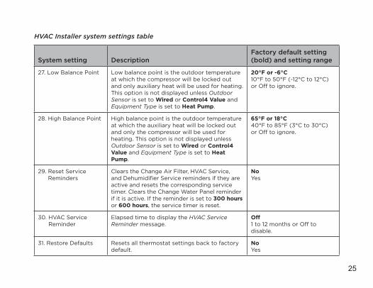
27. Low Balance Point Low balance point is the outdoor temperature at which the compressor will be locked out and only auxiliary heat will be used for heating. This option is not displayed unless Outdoor Sensor is set to Wired or Control4 Value and Equipment Type is set to Heat Pump.
20°F or -6°C 10°F to 50°F (-12°C to 12°C) or Off to ignore.
28. High Balance Point High balance point is the outdoor temperature at which the auxiliary heat will be locked out and only the compressor will be used for heating. This option is not displayed unless Outdoor Sensor is set to Wired or Control4 Value and Equipment Type is set to Heat Pump.
65°F or 18°C 40°F to 85°F (3°C to 30°C) or Off to ignore.
29. Reset Service Reminders
Clears the Change Air Filter, HVAC Service, and Dehumidifier Service reminders if they are active and resets the corresponding service timer. Clears the Change Water Panel reminder if it is active. If the reminder is set to 300 hours or 600 hours, the service timer is reset.
NoYes
30. HVAC Service Reminder
Elapsed time to display the HVAC Service Reminder message.
Off1 to 12 months or Off to disable.
31. Restore Defaults Resets all thermostat settings back to factory default.
NoYes
26
Setup and testing
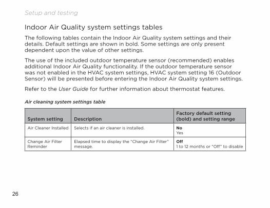
Indoor Air Quality system settings tablesThe following tables contain the Indoor Air Quality system settings and their details. Default settings are shown in bold. Some settings are only present dependent upon the value of other settings.
The use of the included outdoor temperature sensor (recommended) enables additional Indoor Air Quality functionality. If the outdoor temperature sensor was not enabled in the HVAC system settings, HVAC system setting 16 (Outdoor Sensor) will be presented before entering the Indoor Air Quality system settings.
Refer to the User Guide for further information about thermostat features.
Air cleaning system settings table
System setting DescriptionFactory default setting (bold) and setting range
Air Cleaner Installed Selects if an air cleaner is installed. NoYes
Change Air Filter Reminder
Elapsed time to display the “Change Air Filter” message.
Off1 to 12 months or “Off” to disable
27
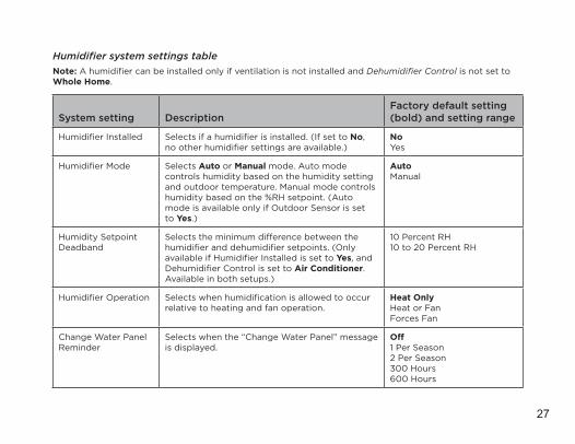
Humidifier system settings tableNote: A humidifier can be installed only if ventilation is not installed and Dehumidifier Control is not set to Whole Home.
System setting DescriptionFactory default setting (bold) and setting range
Humidifier Installed Selects if a humidifier is installed. (If set to No, no other humidifier settings are available.)
NoYes
Humidifier Mode Selects Auto or Manual mode. Auto mode controls humidity based on the humidity setting and outdoor temperature. Manual mode controls humidity based on the %RH setpoint. (Auto mode is available only if Outdoor Sensor is set to Yes.)
AutoManual
Humidity Setpoint Deadband
Selects the minimum difference between the humidifier and dehumidifier setpoints. (Only available if Humidifier Installed is set to Yes, and Dehumidifier Control is set to Air Conditioner. Available in both setups.)
10 Percent RH10 to 20 Percent RH
Humidifier Operation Selects when humidification is allowed to occur relative to heating and fan operation.
Heat OnlyHeat or FanForces Fan
Change Water Panel Reminder
Selects when the “Change Water Panel” message is displayed.
Off1 Per Season2 Per Season300 Hours600 Hours
28
Setup and testing
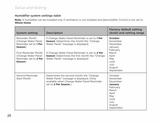
Humidifier system settings tableNote: A humidifier can be installed only if ventilation is not installed and Dehumidifier Control is not set to Whole Home.
System setting DescriptionFactory default setting (bold) and setting range
Reminder Month (Change Water Panel Reminder set to 1 Per Season)
First Reminder Month (Change Water Panel Reminder set to 2 Per Season)
If Change Water Panel Reminder is set to 1 Per Season: Determines the month the “Change Water Panel” message is displayed.
If Change Water Panel Reminder is set to 2 Per Season: Determines the first month the “Change Water Panel” message is displayed.
OctoberNovemberDecemberJanuaryFebruaryMarchAprilMayJuneJulyAugustSeptember
Second Reminder Start Month
Determines the second month the “Change Water Panel” message is displayed. (Only available when Change Water Panel Reminder set to 2 Per Season.)
OctoberNovemberDecemberJanuaryFebruaryMarchAprilMayJuneJulyAugustSeptember
29
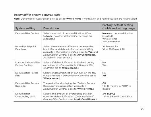
Dehumidifier system settings tableNote: Dehumidifier Control can only be set to Whole Home if ventilation and humidification are not installed.
System setting DescriptionFactory default setting (bold) and setting range
Dehumidifier Control Selects method of dehumidification. (If set to None, no other dehumidifier settings are available.)
None (no dehumidification installed)Whole HomeAir Conditioner
Humidity Setpoint Deadband
Select the minimum difference between the humidifier and dehumidifier setpoints. (Only available if Humidifier Installed is set to Yes, and Dehumidifier Control is set to Air Conditioner. Available in both setups.)
10 Percent RH10 to 20 Percent RH
Lockout Dehumidifier During Cooling
Selects if dehumidification is disabled during a cooling call. (Only available if Dehumidifier Control is set to Whole Home.)
NoYes
Dehumidifier Forces Fan
Selects if dehumidification can turn on the fan. (Only available if Dehumidifier Control is set to Whole Home.)
NoYes
Dehumidifier Service Reminder
The period for displaying the “Dehum Service Reminder” message. (Only available if Dehumidifier Control is set to Whole Home.)
Off1 to 12 months or “Off” to disable
Dehumidifier Overcooling Limit
Selects the amount of overcooling that can occur for dehumidification. (Only available if Dehumidifier Control is set to Air Conditioner.)
3°F (1.5°C)1°F to 3°F (0.5°C to 1.5°C)
30
Setup and testing
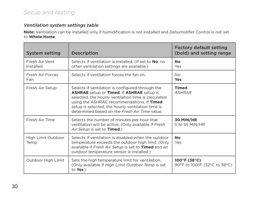
Ventilation system settings tableNote: Ventilation can be installed only if humidification is not installed and Dehumidifier Control is not set to Whole Home.
System setting DescriptionFactory default setting (bold) and setting range
Fresh Air Vent Installed
Selects if ventilation is installed. (If set to No, no other ventilation settings are available.)
NoYes
Fresh Air Forces Fan
Selects if ventilation forces the fan on. NoYes
Fresh Air Setup Selects if ventilation is configured through the ASHRAE setup or Timed. If ASHRAE setup is selected, the hourly ventilation time is calculated using the ASHRAE recommendations. If Timed setup is selected, the hourly ventilation time is determined based on the Fresh Air Time value.
TimedASHRAE
Fresh Air Time Selects the number of minutes per hour that ventilation will be active. (Only available if Fresh Air Setup is set to Timed.)
30 MIN/HR5 to 55 MIN/HR
High Limit Outdoor Temp
Selects if ventilation is disabled when the outdoor temperature exceeds the outdoor high limit. (Only available if Fresh Air Setup is set to Timed and an outdoor temperature sensor is installed.)
NoYes
Outdoor High Limit Sets the high temperature limit for ventilation. (Only available if High Limit Outdoor Temp is set to Yes.)
100°F (38°C)90°F to 100°F (32°C to 38°C)
31
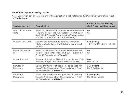
Ventilation system settings tableNote: Ventilation can be installed only if humidification is not installed and Dehumidifier Control is not set to Whole Home.
System setting DescriptionFactory default setting (bold) and setting range
Low Limit Outdoor Temp
Selects if ventilation is disabled when the outdoor temperature exceeds the outdoor low limit. (Only available if Fresh Air Setup is set to Timed and an outdoor temperature sensor is installed.)
NoYes
Outdoor Low Limit Sets the low temperature limit for ventilation. (Only available if Low Limit Outdoor Temp is set to Yes.)
10°F (-12°C)-10°F to 30°F (-24°C to 0°C)
High Limit Indoor RH
Selects if ventilation is disabled when the indoor RH exceeds the indoor RH limit. (Only available if Fresh Air Setup is set to Timed.)
NoYes
Indoor RH Limit Sets the high indoor RH limit for ventilation. (Only available if High Limit Indoor RH is set to Yes.)
60%50% to 70%
Number of Bedrooms
Selects the number of bedrooms to be used for the ASHRAE calculation. (Only available if Fresh Air Setup is set to ASHRAE.)
3 Bedrooms1 to 6 Bedrooms
Number of Occupants
Selects the number of occupants to be used for the ASHRAE calculation. (Only available if Fresh Air Setup is set to ASHRAE.)
4 Occupants1 to 10 Occupants
32
Setup and testing
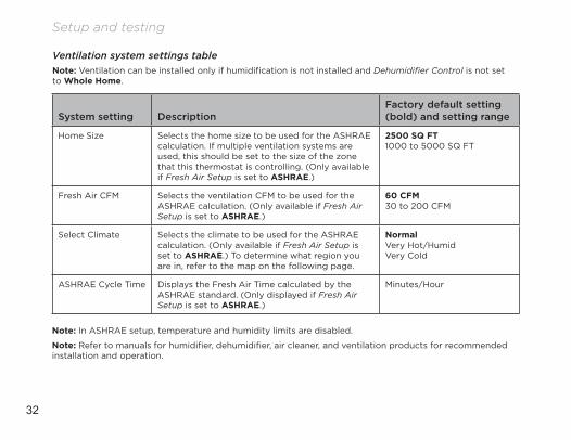
Ventilation system settings tableNote: Ventilation can be installed only if humidification is not installed and Dehumidifier Control is not set to Whole Home.
System setting DescriptionFactory default setting (bold) and setting range
Home Size Selects the home size to be used for the ASHRAE calculation. If multiple ventilation systems are used, this should be set to the size of the zone that this thermostat is controlling. (Only available if Fresh Air Setup is set to ASHRAE.)
2500 SQ FT1000 to 5000 SQ FT
Fresh Air CFM Selects the ventilation CFM to be used for the ASHRAE calculation. (Only available if Fresh Air Setup is set to ASHRAE.)
60 CFM30 to 200 CFM
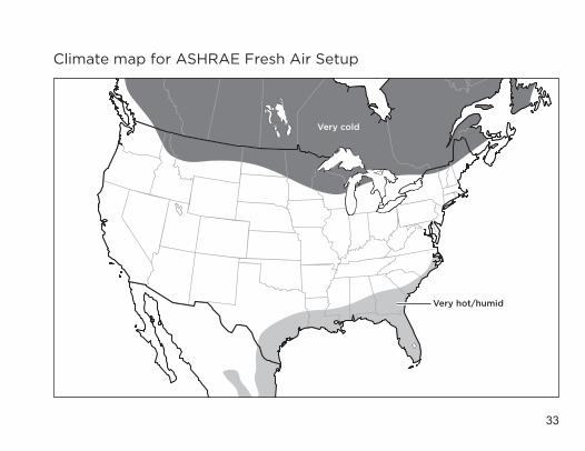
Select Climate Selects the climate to be used for the ASHRAE calculation. (Only available if Fresh Air Setup is set to ASHRAE.) To determine what region you are in, refer to the map on the following page.
NormalVery Hot/HumidVery Cold
ASHRAE Cycle Time Displays the Fresh Air Time calculated by the ASHRAE standard. (Only displayed if Fresh Air Setup is set to ASHRAE.)
Minutes/Hour
Note: In ASHRAE setup, temperature and humidity limits are disabled.
Note: Refer to manuals for humidifier, dehumidifier, air cleaner, and ventilation products for recommended installation and operation.
33
Climate map for ASHRAE Fresh Air Setup
Very hot/humid
Very cold
34
Setup and testing
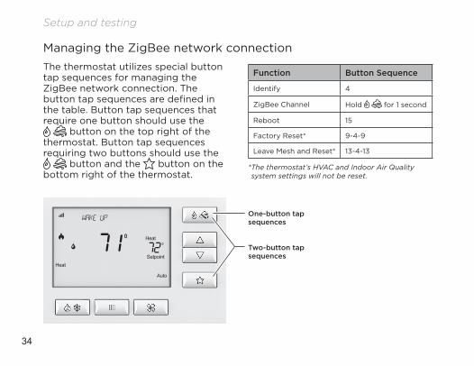
Function Button Sequence
Identify 4
ZigBee Channel Hold for 1 second
Reboot 15
Factory Reset* 9-4-9
Leave Mesh and Reset* 13-4-13
* The thermostat’s HVAC and Indoor Air Quality system settings will not be reset.
Managing the ZigBee network connectionThe thermostat utilizes special button tap sequences for managing the ZigBee network connection. The button tap sequences are defined in the table. Button tap sequences that require one button should use the
button on the top right of the thermostat. Button tap sequences requiring two buttons should use the
button and the button on the bottom right of the thermostat.
One-button tap sequences
Two-button tap sequences
35
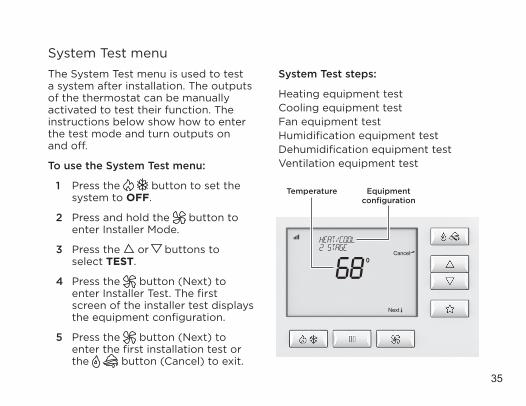
System Test menuThe System Test menu is used to test a system after installation. The outputs of the thermostat can be manually activated to test their function. The instructions below show how to enter the test mode and turn outputs on and off.
To use the System Test menu:
1 Press the button to set the system to OFF.
2 Press and hold the button to enter Installer Mode.
3 Press the or buttons to select TEST.
4 Press the button (Next) to enter Installer Test. The first screen of the installer test displays the equipment configuration.
5 Press the button (Next) to enter the first installation test or the button (Cancel) to exit.
System Test steps:
Heating equipment testCooling equipment testFan equipment testHumidification equipment testDehumidification equipment testVentilation equipment test
Temperature Equipment configuration
36
Setup and testing
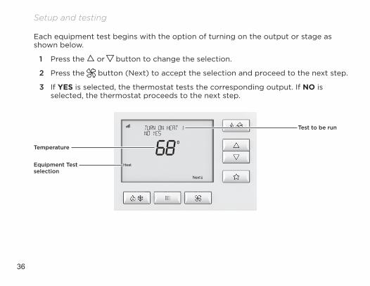
Each equipment test begins with the option of turning on the output or stage as shown below.
1 Press the or button to change the selection.
2 Press the button (Next) to accept the selection and proceed to the next step.
3 If YES is selected, the thermostat tests the corresponding output. If NO is selected, the thermostat proceeds to the next step.
Temperature
Equipment Test selection
Test to be run
37
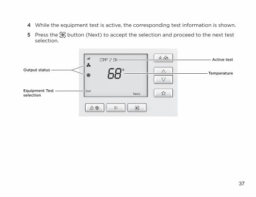
4 While the equipment test is active, the corresponding test information is shown.
5 Press the button (Next) to accept the selection and proceed to the next test selection.
Output status
Equipment Test selection
Temperature
Active test
38
Setup and testing
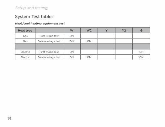
System Test tables
Heat/cool heating equipment test
Heat type W W2 Y Y2 G
Gas First-stage test ON
Gas Second-stage test ON ON
Electric First-stage Test ON ON
Electric Second-stage test ON ON ON
39
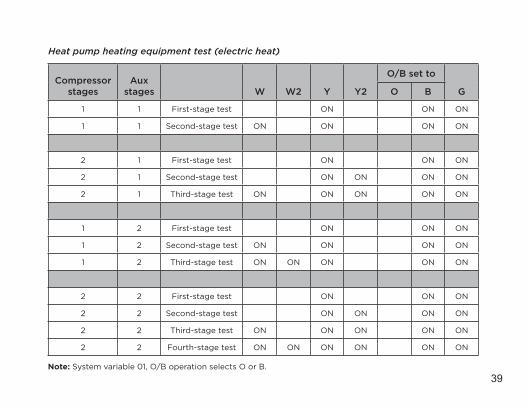
Heat pump heating equipment test (electric heat)
Compressor stages
Aux stages W W2 Y Y2
O/B set to
GO B
1 1 First-stage test ON ON ON
1 1 Second-stage test ON ON ON ON
2 1 First-stage test ON ON ON
2 1 Second-stage test ON ON ON ON
2 1 Third-stage test ON ON ON ON ON
1 2 First-stage test ON ON ON
1 2 Second-stage test ON ON ON ON
1 2 Third-stage test ON ON ON ON ON
2 2 First-stage test ON ON ON
2 2 Second-stage test ON ON ON ON
2 2 Third-stage test ON ON ON ON ON
2 2 Fourth-stage test ON ON ON ON ON ON
Note: System variable 01, O/B operation selects O or B.
40
Setup and testing
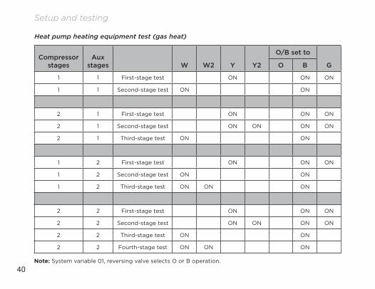
Heat pump heating equipment test (gas heat)
Compressor stages
Aux stages W W2 Y Y2
O/B set to
GO B
1 1 First-stage test ON ON ON
1 1 Second-stage test ON ON
2 1 First-stage test ON ON ON
2 1 Second-stage test ON ON ON ON
2 1 Third-stage test ON ON
1 2 First-stage test ON ON ON
1 2 Second-stage test ON ON
1 2 Third-stage test ON ON ON
2 2 First-stage test ON ON ON
2 2 Second-stage test ON ON ON ON
2 2 Third-stage test ON ON
2 2 Fourth-stage test ON ON ON
Note: System variable 01, reversing valve selects O or B operation.
41
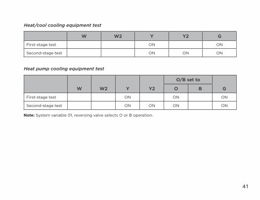
Heat/cool cooling equipment test
W W2 Y Y2 G
First-stage test ON ON
Second-stage test ON ON ON
Heat pump cooling equipment test
W W2 Y Y2
O/B set to
GO B
First-stage test ON ON ON
Second-stage test ON ON ON ON Note: System variable 01, reversing valve selects O or B operation.
42
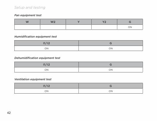
Setup and testing
Fan equipment test
W W2 Y Y2 G
ON
Humidification equipment test
I1/I2 G
ON ON
Dehumidification equipment test
I1/I2 G
ON ON
Ventilation equipment test
I1/I2 G
ON ON
43
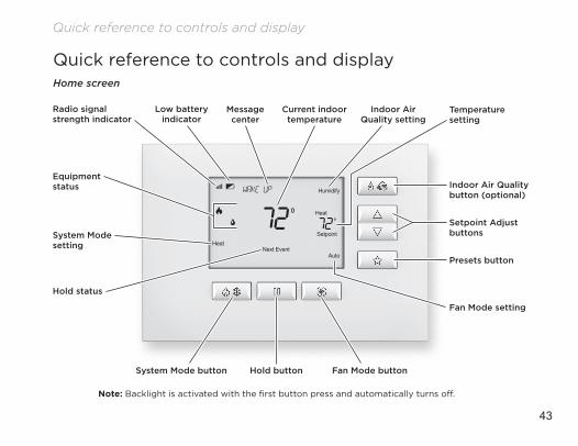
Quick reference to controls and displayHome screen
Note: Backlight is activated with the first button press and automatically turns off.
Equipment status
System Mode setting
System Mode button Hold button Fan Mode button
Indoor Air Quality button (optional)
Setpoint Adjust buttons
Temperature setting
Fan Mode setting
Presets button
Hold status
Radio signal strength indicator
Low battery indicator
Message center
Indoor Air Quality setting
Current indoor temperature
Quick reference to controls and display
44
Troubleshooting
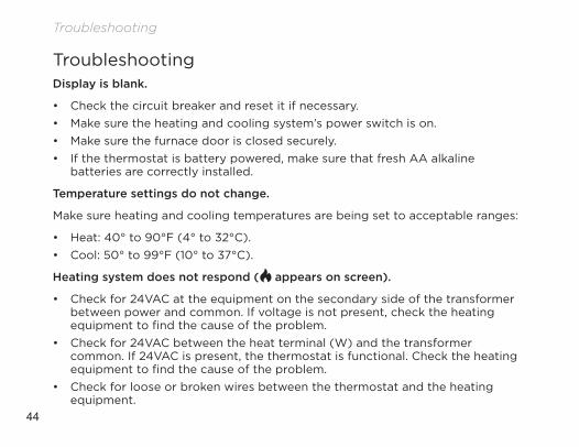
TroubleshootingDisplay is blank.
• Check the circuit breaker and reset it if necessary.• Make sure the heating and cooling system’s power switch is on.• Make sure the furnace door is closed securely.• If the thermostat is battery powered, make sure that fresh AA alkaline
batteries are correctly installed.
Temperature settings do not change.
Make sure heating and cooling temperatures are being set to acceptable ranges:
• Heat: 40° to 90°F (4° to 32°C).• Cool: 50° to 99°F (10° to 37°C).
Heating system does not respond ( appears on screen).
• Check for 24VAC at the equipment on the secondary side of the transformer between power and common. If voltage is not present, check the heating equipment to find the cause of the problem.
• Check for 24VAC between the heat terminal (W) and the transformer common. If 24VAC is present, the thermostat is functional. Check the heating equipment to find the cause of the problem.
• Check for loose or broken wires between the thermostat and the heating equipment.
45
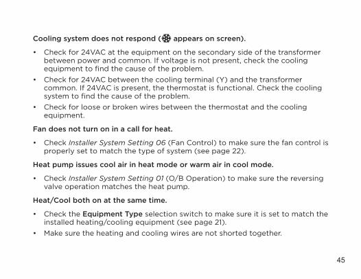
Cooling system does not respond ( appears on screen).
• Check for 24VAC at the equipment on the secondary side of the transformer between power and common. If voltage is not present, check the cooling equipment to find the cause of the problem.
• Check for 24VAC between the cooling terminal (Y) and the transformer common. If 24VAC is present, the thermostat is functional. Check the cooling system to find the cause of the problem.
• Check for loose or broken wires between the thermostat and the cooling equipment.
Fan does not turn on in a call for heat.
• Check Installer System Setting 06 (Fan Control) to make sure the fan control is properly set to match the type of system (see page 22).
Heat pump issues cool air in heat mode or warm air in cool mode.
• Check Installer System Setting 01 (O/B Operation) to make sure the reversing valve operation matches the heat pump.
Heat/Cool both on at the same time.
• Check the Equipment Type selection switch to make sure it is set to match the installed heating/cooling equipment (see page 21).
• Make sure the heating and cooling wires are not shorted together.
46
Troubleshooting
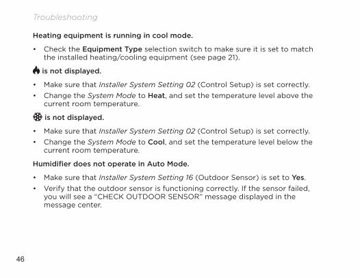
Heating equipment is running in cool mode.
• Check the Equipment Type selection switch to make sure it is set to match the installed heating/cooling equipment (see page 21).
is not displayed.
• Make sure that Installer System Setting 02 (Control Setup) is set correctly.• Change the System Mode to Heat, and set the temperature level above the
current room temperature.
is not displayed.
• Make sure that Installer System Setting 02 (Control Setup) is set correctly.• Change the System Mode to Cool, and set the temperature level below the
current room temperature.
Humidifier does not operate in Auto Mode.
• Make sure that Installer System Setting 16 (Outdoor Sensor) is set to Yes.• Verify that the outdoor sensor is functioning correctly. If the sensor failed,
you will see a “CHECK OUTDOOR SENSOR” message displayed in the message center.
47
Error codes
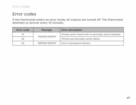
Error codesIf the thermostat enters an error mode, all outputs are turned off. The thermostat attempts to recover every 10 minutes.
Error code Message Error description
01 “SENSOR ERROR”
Primary sensor failure with no secondary sensor assigned.
02 Primary and secondary sensor failure.
03 “EEPROM ERROR” Error in permanent memory.
48
Thermostat features
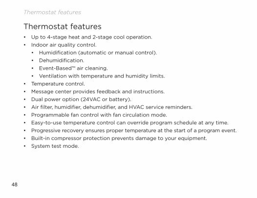
Thermostat features• Up to 4-stage heat and 2-stage cool operation.• Indoor air quality control.
• Humidification (automatic or manual control).• Dehumidification.• Event-Based™ air cleaning.• Ventilation with temperature and humidity limits.
• Temperature control.• Message center provides feedback and instructions.• Dual power option (24VAC or battery).• Air filter, humidifier, dehumidifier, and HVAC service reminders.• Programmable fan control with fan circulation mode.• Easy-to-use temperature control can override program schedule at any time.• Progressive recovery ensures proper temperature at the start of a program event.• Built-in compressor protection prevents damage to your equipment.• System test mode.
49
Specifications
Specifications
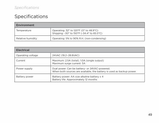
Environment
Temperature Operating: 32° to 120°F (0° to 48.9°C) Shipping: -30° to 150°F (-34.4° to 65.5°C)
Relative humidity Operating: 5% to 90% R.H. (non-condensing)
Electrical
Operating voltage 24VAC (19.2–28.8VAC)
Current Maximum: 2.5A (total), 1.0A (single output) Maximum surge current: 5A
Power supply Dual power. Can be battery- or 24VAC-powered.When both sources are available, the battery is used as backup power.
Battery power Battery power: AA size alkaline battery x 4 Battery life: Approximately 12 months
50
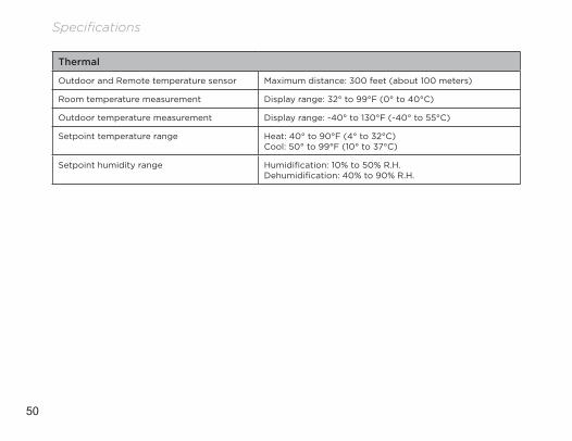
Specifications
Thermal
Outdoor and Remote temperature sensor Maximum distance: 300 feet (about 100 meters)
Room temperature measurement Display range: 32° to 99°F (0° to 40°C)
Outdoor temperature measurement Display range: -40° to 130°F (-40° to 55°C)
Setpoint temperature range Heat: 40° to 90°F (4° to 32°C) Cool: 50° to 99°F (10° to 37°C)
Setpoint humidity range Humidification: 10% to 50% R.H. Dehumidification: 40% to 90% R.H.

51
U.S. Patent Number 8,146,376 (and other patents pending).

control4.com | 888.400.4070 61001048G 3 .15