Embed Size (px)
Citation preview

Robot Controller Control Unit RC700 RC700-A
Drive Unit RC700DU RC700DU-A
Programming Software EPSON RC+7.0
Manipulator G1 G3 G6 G10 G20 series RS series
C4 C8 series N2 series X5 series
Robot SystemSafety and Installation
Read this manual first
Rev.14 EM174B3448F

Robot S
ystem S
afety and Installation (RC
700 / EP
SO
N R
C+7.0) R
ev.14
Safety and Installation (RC700 / EPSON RC+ 7.0) Rev.14 i
Robot System Safety and Installation (RC700 / EPSON RC+7.0)
Rev.14
Copyright 2012-2017 SEIKO EPSON CORPORATION. All rights reserved.

ii Safety and Installation (RC700 / EPSON RC+ 7.0) Rev.14
FOREWORD Thank you for purchasing our robot products.
This manual contains the information necessary for the correct use of the robot
system.
Please carefully read this manual and other related manuals before installing the
robot system.
Keep this manual handy for easy access at all times. WARRANTY
The robot system and its optional parts are shipped to our customers only after
being subjected to the strictest quality controls, tests, and inspections to certify its
compliance with our high performance standards.
Product malfunctions resulting from normal handling or operation will be repaired
free of charge during the normal warranty period. (Please ask your Regional Sales
Office for warranty period information.)
However, customers will be charged for repairs in the following cases (even if they
occur during the warranty period):
1. Damage or malfunction caused by improper use which is not described in
the manual, or careless use.
2. Malfunctions caused by customers’ unauthorized disassembly.
3. Damage due to improper adjustments or unauthorized repair attempts.
4. Damage caused by natural disasters such as earthquake, flood, etc.
Warnings, Cautions, Usage:
1. If the robot system associated equipment is used outside of the usage
conditions and product specifications described in the manuals, this
warranty is void.
2. If you do not follow the WARNINGS and CAUTIONS in this manual, we
cannot be responsible for any malfunction or accident, even if the result is
injury or death.
3. We cannot foresee all possible dangers and consequences. Therefore, this
manual cannot warn the user of all possible hazards.
Safety and Installation (RC700 / EPSON RC+ 7.0) Rev.14 iii
TRADEMARKS Microsoft, Windows, and Windows logo are either registered trademarks or
trademarks of Microsoft Corporation in the United States and/or other countries.
Other brand and product names are trademarks or registered trademarks of the
respective holders. TRADEMARK NOTATION IN THIS MANUAL
Microsoft® Windows® XP Operating system
Microsoft® Windows® Vista Operating system
Microsoft® Windows® 7 Operating system
Microsoft® Windows® 8 Operating system
Microsoft® Windows® 10 Operating system
Throughout this manual, Windows XP, Windows Vista, Windows 7, Windows 8,
and Windows 10 refer to above respective operating systems. In some cases,
Windows refers generically to Windows XP, Windows Vista, Windows 7,
Windows 8, and Windows 10. NOTICE
No part of this manual may be copied or reproduced without authorization.
The contents of this manual are subject to change without notice.
Please notify us if you should find any errors in this manual or if you have any
comments regarding its contents. MANUFACTURER Seiko Epson Corporation
3-3-5 Owa, Suwa-shi, Nagano, 392-8502
URL : http://global.epson.com/company/
: http://www.epson.jp/prod/robots/
Toyoshina Plant Robotics Solutions Operations Division 6925 Toyoshina Tazawa, Azumino-shi, Nagano, 399-8285 Japan
TEL : +81-(0)263-72-1530
FAX : +81-(0)263-72-1495

iv Safety and Installation (RC700 / EPSON RC+ 7.0) Rev.14
SUPPLIERS North & South
America Epson America, Inc.
Factory Automation/Robotics 18300 Central Avenue Carson, CA 90746 USA
TEL : +1-562-290-5900
FAX : +1-562-290-5999
E-MAIL : [email protected]
Europe Epson Deutschland GmbH
Robotic Solutions Otto-Hahn-Str.4 D-40670 Meerbusch Germany
TEL : +49-(0)-2159-538-1800
FAX : +49-(0)-2159-538-3170
E-MAIL : [email protected]
URL: : www.epson.de/robots
China Epson (China) Co., Ltd.
Factory Automation Division 4F, Tower 1, China Central Place, 81 Jianguo Road, Chaoyang District, Beijing, 100025, PRC
TEL : +86-(0)-10-8522-1199
FAX : +86-(0)-10-8522-1120
Taiwan Epson Taiwan Technology & Trading Ltd.
Factory Automation Division 14F, No.7, Song Ren Road, Taipei 11073, Taiwan, ROC
TEL : +886-(0)-2-8786-6688
FAX : +886-(0)-2-8786-6677

Safety and Installation (RC700 / EPSON RC+ 7.0) Rev.14 v
Korea Epson Korea Co., Ltd.
Marketing Team (Robot Business) 27F DaeSung D-Polis A, 606 Seobusaet-gil, Geumcheon-gu, Seoul, 153-803 Korea
TEL : +82-(0)-2-3420-6692
FAX : +82-(0)-2-558-4271
Southeast Asia Epson Singapore Pte. Ltd.
Factory Automation System 1 HarbourFront Place, #03-02, HarbourFront Tower One, Singapore 098633
TEL : +65-(0)-6586-5696
FAX : +65-(0)-6271-3182
India Epson India Pvt. Ltd.
Sales & Marketing (Factory Automation) 12th Floor, The Millenia, Tower A, No. 1, Murphy Road, Ulsoor, Bangalore, India 560008
TEL : +91-80-3051-5000
FAX : +91-80-3051-5005
Japan Epson Sales Japan Corporation
Factory Automation Systems Department Nishi-Shinjuku Mitsui Bldg.6-24-1 Nishishinjuku, Shinjuku-ku, Tokyo 160-8324 Japan
TEL :+81-(0)3-5321-4161
vi Safety and Installation (RC700 / EPSON RC+ 7.0) Rev.14
Regarding battery disposal
The crossed out wheeled bin label that can be found on your product indicates that this
product and incorporated batteries should not be disposed of via the normal household
waste stream. To prevent possible harm to the environment or human health please
separate this product and its batteries from other waste streams to ensure that it can be
recycled in an environmentally sound manner. For more details on available collection
facilities please contact your local government office or the retailer where you purchased
this product. Use of the chemical symbols Pb, Cd or Hg indicates if these metals are
used in the battery.
This information only applies to customers in the European Union, according to
DIRECTIVE 2006/66/EC OF THE EUROPEAN PARLIAMENT AND OF THE COUNCIL
OF 6 September 2006 on batteries and accumulators and waste batteries and
accumulators and repealing Directive 91/157/EEC and legislation transposing and
implementing it into the various national legal systems.
For other countries, please contact your local government to investigate the possibility of
recycling your product.
The battery removal/replacement procedure is described in the following manuals:
Controller manual / Manipulator manual (Maintenance section)
For California customers only The lithium batteries in this product contain
Perchlorate Material - special handling may apply,
See www.dtsc.ca.gov/hazardouswaste/perchlorate.

Safety and Installation (RC700 / EPSON RC+ 7.0) Rev.14 vii
Before Reading This Manual
Concerning the security support for the network connection:
The network connecting function (Ethernet) on our products assumes the use
in the local network such as the factory LAN network. Do not connect to the
external network such as Internet.
In addition, please take security measure such as for the virus from the
network connection by installing the antivirus software.
Security support for the USB memory:
Make sure the USB memory is not infected with virus when connecting to the
Controller.
Control System Configuration
Robot Controller Drive Unit RC700DU is available for the following version.
EPSON RC+ 7.0 Ver.7.1.0 or later
Robot Controller RC700-A Robot Controller Drive Unit RC700DU-A is available for the following version.
EPSON RC+ 7.0 Ver.7.1.2 or later
Manipulators can be connected with the following versions.
C4 series : EPSON RC+ 7.0 Ver.7.0.0
C8 series (C8XL) : EPSON RC+ 7.0 Ver.7.1.3
C8 series (C8, C8L) : EPSON RC+ 7.0 Ver.7.1.4
C8 series (wall mounting) : EPSON RC+ 7.0 Ver.7.2.0
N2 series : EPSON RC+ 7.0 Ver.7.2.0
G1, G3, G6, G10, G20, RS series : EPSON RC+ 7.0 Ver.7.1.2
X5 series : EPSON RC+ 7.0 Ver.7.3.0
NOTE
NOTE

viii Safety and Installation (RC700 / EPSON RC+ 7.0) Rev.14
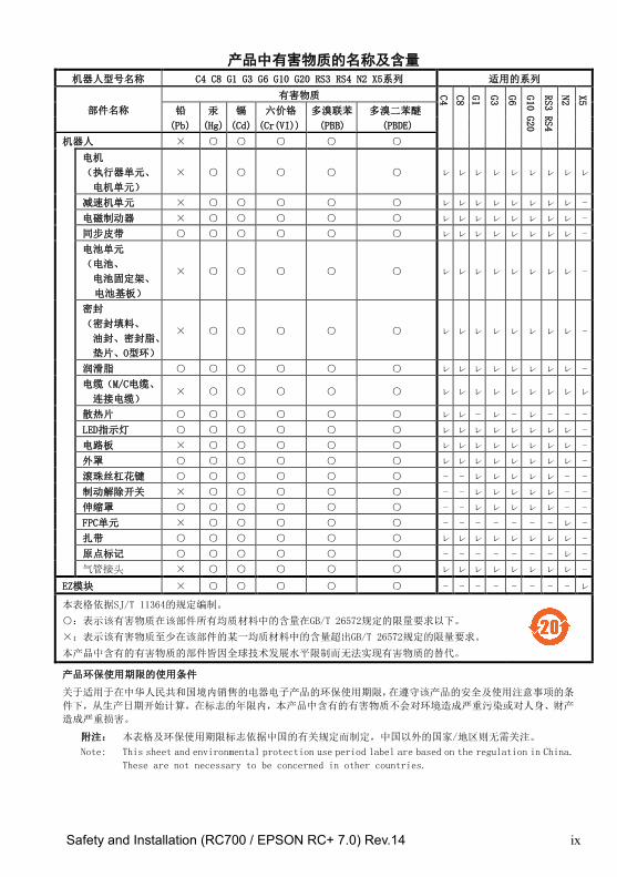
China RoHS This sheet and environmental protection use period label are based on the
regulation in China. These are not necessary to be concerned in other
countries.
Safety and Installation (RC700 / EPSON RC+ 7.0) Rev.14 ix
产品中有害物质的名称及含量
机器人型号名称 C4 C8 G1 G3 G6 G10 G20 RS3 RS4 N2 X5系列 适用的系列
部件名称
有害物质 C4
C8
G1
G3
G6
G10
G20
RS3
RS4
N2
X5
铅 汞 镉 六价铬 多溴联苯 多溴二苯醚
(Pb) (Hg) (Cd) (Cr(VI)) (PBB) (PBDE)
机器人 ×
电机
(执行器单元、
电机单元)
× ㇾ ㇾ ㇾ ㇾ ㇾ ㇾ ㇾ ㇾ ㇾ
减速机单元 × ㇾ ㇾ ㇾ ㇾ ㇾ ㇾ ㇾ ㇾ -
电磁制动器 × ㇾ ㇾ ㇾ ㇾ ㇾ ㇾ ㇾ ㇾ -
同步皮带 ㇾ ㇾ ㇾ ㇾ ㇾ ㇾ ㇾ ㇾ -
电池单元
(电池、
电池固定架、
电池基板)
× ㇾ ㇾ ㇾ ㇾ ㇾ ㇾ ㇾ ㇾ -
密封
(密封填料、
油封、密封脂、
垫片、O型环)
× ㇾ ㇾ ㇾ ㇾ ㇾ ㇾ ㇾ ㇾ -
润滑脂 ㇾ ㇾ ㇾ ㇾ ㇾ ㇾ ㇾ ㇾ -
电缆(M/C电缆、
连接电缆) × ㇾ ㇾ ㇾ ㇾ ㇾ ㇾ ㇾ ㇾ ㇾ
散热片 ㇾ ㇾ - ㇾ - ㇾ - - -
LED指示灯 ㇾ ㇾ ㇾ ㇾ ㇾ ㇾ ㇾ ㇾ -
电路板 × ㇾ ㇾ ㇾ ㇾ ㇾ ㇾ ㇾ ㇾ -
外罩 ㇾ ㇾ ㇾ ㇾ ㇾ ㇾ ㇾ ㇾ -
滚珠丝杠花键 - - ㇾ ㇾ ㇾ ㇾ ㇾ - -
制动解除开关 × - - ㇾ ㇾ ㇾ ㇾ ㇾ - -
伸缩罩 - - ㇾ ㇾ ㇾ ㇾ ㇾ - -
FPC单元 × - - - - - - - ㇾ -
扎带 ㇾ ㇾ ㇾ ㇾ ㇾ ㇾ ㇾ ㇾ -
原点标记 - - - - - - - ㇾ -
气管接头 × ㇾ ㇾ ㇾ ㇾ ㇾ ㇾ ㇾ ㇾ -
EZ模块 × - - - - - - - - ㇾ
本表格依据SJ/T 11364的规定编制。
:表示该有害物质在该部件所有均质材料中的含量在GB/T 26572规定的限量要求以下。
×:表示该有害物质至少在该部件的某一均质材料中的含量超出GB/T 26572规定的限量要求。
本产品中含有的有害物质的部件皆因全球技术发展水平限制而无法实现有害物质的替代。
产品环保使用期限的使用条件
关于适用于在中华人民共和国境内销售的电器电子产品的环保使用期限,在遵守该产品的安全及使用注意事项的条
件下,从生产日期开始计算,在标志的年限内,本产品中含有的有害物质不会对环境造成严重污染或对人身、财产
造成严重损害。
附注: 本表格及环保使用期限标志依据中国的有关规定而制定,中国以外的国家/地区则无需关注。
Note: This sheet and environmental protection use period label are based on the regulation in China.
These are not necessary to be concerned in other countries.

x Safety and Installation (RC700 / EPSON RC+ 7.0) Rev.14
产品中有害物质的名称及含量
机器人型号名称 C4 C8 G1 G3 G6 G10 G20 RS3 RS4 N2 X5系列 适用的系列
部件名称
有害物质 C4
C8
G1
G3
G6
G10
G20
RS3
RS4
N2
X5
铅 汞 镉 六价铬 多溴联苯 多溴二苯醚
(Pb) (Hg) (Cd) (Cr(VI)) (PBB) (PBDE)
选
件
制动解除单元 × ㇾ ㇾ - - - - - ㇾ -
相机安装板 ㇾ ㇾ - ㇾ ㇾ ㇾ ㇾ ㇾ ㇾ
PS兼容板
(工具适配器) × ㇾ ㇾ - - - - - ㇾ -
底座侧固定金属件 × ㇾ ㇾ - - - - - - -
可调机械挡块 × ㇾ ㇾ - - - - - - -
MC短接连接器 × - ㇾ - - - - - ㇾ -
用户接头套件 × ㇾ ㇾ - - - - - ㇾ -
用户连接器套件 × ㇾ ㇾ - - - - - ㇾ -
原点调整板 × - - - - - - - ㇾ -
地面支架 × - - - - - - - ㇾ -
配线引导装置 × - - - - - - - ㇾ -
本表格依据SJ/T 11364的规定编制。
:表示该有害物质在该部件所有均质材料中的含量在GB/T 26572规定的限量要求以下。
×:表示该有害物质至少在该部件的某一均质材料中的含量超出GB/T 26572规定的限量要求。
本产品中含有的有害物质的部件皆因全球技术发展水平限制而无法实现有害物质的替代。
产品环保使用期限的使用条件
关于适用于在中华人民共和国境内销售的电器电子产品的环保使用期限,在遵守该产品的安全及使用注意事项的条
件下,从生产日期开始计算,在标志的年限内,本产品中含有的有害物质不会对环境造成严重污染或对人身、财产
造成严重损害。
附注: 本表格及环保使用期限标志依据中国的有关规定而制定,中国以外的国家/地区则无需关注。
Note: This sheet and environmental protection use period label are based on the regulation in China.
These are not necessary to be concerned in other countries.

Safety and Installation (RC700 / EPSON RC+ 7.0) Rev.14 xi
产品中有害物质的名称及含量
控制器型号名称 RC700 RC700-A RC700DU RC700DU-A系列 适用的系列
部件名称
有害物质 RC7
00
RC7
00-A
RC7
00DU
RC7
00DU-
A
铅 汞 镉 六价铬 多溴联苯 多溴二苯醚
(Pb) (Hg) (Cd) (Cr(VI)) (PBB) (PBDE)
控制器 ×
机壳 ㇾ ㇾ ㇾ ㇾ
电路板 × ㇾ ㇾ ㇾ ㇾ
开关电源 × ㇾ ㇾ ㇾ ㇾ
风扇 × ㇾ ㇾ ㇾ ㇾ
线束 × ㇾ ㇾ ㇾ ㇾ
电源保护装置 × ㇾ ㇾ ㇾ ㇾ
存储卡 × ㇾ ㇾ ㇾ ㇾ
电池 ㇾ ㇾ ㇾ ㇾ
连接器附件 × ㇾ ㇾ ㇾ ㇾ
本表格依据SJ/T 11364的规定编制。
:表示该有害物质在该部件所有均质材料中的含量在GB/T 26572规定的限量要求以下。
×:表示该有害物质至少在该部件的某一均质材料中的含量超出GB/T 26572规定的限量要求。
本产品中含有的有害物质的部件皆因全球技术发展水平限制而无法实现有害物质的替代。
产品环保使用期限的使用条件
关于适用于在中华人民共和国境内销售的电器电子产品的环保使用期限,在遵守该产品的安全及使用注
意事项的条件下,从生产日期开始计算,在标志的年限内,本产品中含有的有害物质不会对环境造成严
重污染或对人身、财产造成严重损害。
附注: 本表格及环保使用期限标志依据中国的有关规定而制定,中国以外的国家/地区则无需关注。
Note: This sheet and environmental protection use period label are based on the regulation
in China. These are not necessary to be concerned in other countries.

xii Safety and Installation (RC700 / EPSON RC+ 7.0) Rev.14
产品中有害物质的名称及含量
控制器型号名称 RC700 RC700-A RC700DU RC700DU-A系列 适用的系列
部件名称
有害物质 RC7
00
RC7
00-A
RC7
00DU
RC7
00DU-
A 铅 汞 镉 六价铬 多溴联苯 多溴二苯醚
(Pb) (Hg) (Cd) (Cr(VI)) (PBB) (PBDE)
选
件
电路板 × ㇾ ㇾ - -
接线 × ㇾ ㇾ ㇾ ㇾ
接线端子 × ㇾ ㇾ ㇾ ㇾ
紧急停止开关 × ㇾ ㇾ ㇾ ㇾ
TP1 × ㇾ ㇾ - -
TP2 × ㇾ ㇾ - -
TP3 × - ㇾ - -
墙面安装金属件 × ㇾ ㇾ - -
Hot Plug Kit × - ㇾ - -
CK1 × ㇾ ㇾ - -
CV1 × ㇾ ㇾ - -
CV2 × ㇾ ㇾ - -
相机 × ㇾ ㇾ - -
延长管 × ㇾ ㇾ - -
GigE相机PoE
转换器 × ㇾ ㇾ - -
GigE相机PoE
交换集线器 × ㇾ ㇾ - -
GigE相机三脚
架适配器 × ㇾ ㇾ - -
以太网交换机 × ㇾ ㇾ - -
力传感器 × ㇾ ㇾ - -
力传感器I/F单元 × ㇾ ㇾ - -
USB选件密钥
× ㇾ ㇾ - -
本表格依据SJ/T 11364的规定编制。
:表示该有害物质在该部件所有均质材料中的含量在GB/T 26572规定的限量要求以下。
×:表示该有害物质至少在该部件的某一均质材料中的含量超出GB/T 26572规定的限量要求。
本产品中含有的有害物质的部件皆因全球技术发展水平限制而无法实现有害物质的替代。
产品环保使用期限的使用条件
关于适用于在中华人民共和国境内销售的电器电子产品的环保使用期限,在遵守该产品的安全及使用注
意事项的条件下,从生产日期开始计算,在标志的年限内,本产品中含有的有害物质不会对环境造成严
重污染或对人身、财产造成严重损害。
附注: 本表格及环保使用期限标志依据中国的有关规定而制定,中国以外的国家/地区则无需关注。
Note: This sheet and environmental protection use period label are based on the regulation
in China. These are not necessary to be concerned in other countries.

Table of Contents
Safety and Installation (RC700 / EPSON RC+ 7.0) Rev.14 xiii
1. Safety 1
1.1 Conventions ······································································· 1 1.2 Design and Installation Safety ················································ 2
1.2.1 Relevant Manuals ······················································ 2 1.2.2 Designing a Safe Robot System ··································· 3
1.3 Operation Safety ································································· 8 1.3.1 Safety-related Requirements ······································ 10 1.3.2 Part Names / Arm Motion ·········································· 11 1.3.3 Operation Modes ····················································· 32
1.4 Maintenance Safety ··························································· 33 1.5 Emergency Stop ······························································· 36
1.5.1 Free running distance in emergency ···························· 40 1.5.2 How to reset the emergency mode ······························ 48
1.6 Labels ············································································· 49 1.6.1 Controller ······························································· 49 1.6.2 Manipulator ···························································· 51
1.7 Safety Features ································································ 64 1.8 Manipulator Specifications ·················································· 67 1.9 Motion Range Setting by Mechanical Stops ·························· 108 1.10 End User Training ·························································· 125
2. Installation 126
System Example ···································································· 127 2.1 Outline from Unpacking to Operation of Robot System ············ 131 2.2 Unpacking ····································································· 132
2.2.1 Unpacking Precautions ··········································· 132 2.3 Transportation ································································ 133
2.3.1 Transportation Precautions ······································ 133 2.3.2 Manipulator Transportation ······································ 134
2.4 Manipulator Installation ····················································· 140 2.4.1 Installation Precautions ··········································· 140 2.4.2 Environment ························································· 141 2.4.3 Noise level ··························································· 142 2.4.4 Base Table ··························································· 143 2.4.5 Installation Procedure ············································· 145
2.5 Control unit and Drive unit Installation ·································· 158 2.5.1 Environment ························································· 158 2.5.2 Installation···························································· 160 2.5.3 Wall Mounting Option ············································· 161
Table of Contents
xiv Safety and Installation (RC700 / EPSON RC+ 7.0) Rev.14
2.6 Connection to EMERGENCY Connector ······························· 162
2.6.1 Safety Door Switch and Latch Release Switch ············· 162 2.6.2 Safety Door Switch ················································· 163 2.6.3 Latch Release Switch ·············································· 163 2.6.4 Checking Latch Release Switch Operation ·················· 164 2.6.5 Emergency Stop Switch ··········································· 165 2.6.6 Checking Emergency Stop Switch Operation ··············· 165 2.6.7 Pin Assignments ···················································· 167 2.6.8 Circuit Diagrams – Control unit ·································· 168 2.6.9 Circuit Diagrams – Drive unit ···································· 170
2.7 Power supply, AC power cable ··········································· 174 2.7.1 Power Supply ························································ 174 2.7.2 AC Power Cable ···················································· 175
2.8 Drive Unit Connection ······················································· 176 2.9 Drive Unit Setup ······························································ 177 2.10 Connecting Manipulator and Controller ······························· 178
2.10.1 Connecting Precautions ········································· 178 2.11 Power-on ······································································ 179
2.11.1 Power-on Precautions ··········································· 179 2.11.2 Power ON Procedure ············································ 181
2.12 Saving Default Status ······················································ 182 2.13 Adding Information of the Additional System ························ 182
3. First Step 185
3.1 Installing EPSON RC+ 7.0 Software ···································· 185 3.2 Development PC and Controller Connection ·························· 188
3.2.1 About Development PC Connection USB Port ·············· 188 3.2.2 Precaution ···························································· 189 3.2.3 Software Setup and Connection Check ······················· 189 3.2.4 Backup the initial condition of the Controller ················· 190 3.2.5 Disconnection of Development PC and Controller ········· 191 3.2.6 Moving the Robot to Initial Position ···························· 191
3.3 Writing your first program ·················································· 196
4. Second Step 203 4.1 Connection with External Equipment ···································· 203
4.1.1 Remote Control······················································ 203 4.1.2 Ethernet ······························································· 203

Table of Contents
Safety and Installation (RC700 / EPSON RC+ 7.0) Rev.14 xv
4.1.3 RS-232C (Option) ·················································· 203 4.1.4 Analog I/O board (Option)········································ 203 4.1.5 Force Sensor I/F board (Option) ······························· 203
4.2 Ethernet Connection of Development PC and Controller ·········· 204 4.3 Connection of Teach Pendant (Option) ································ 204
5. General Maintenance 205
5.1 Maintenance ·································································· 205 5.1.1 Manipulator ·························································· 205 5.1.2 Control Unit (RC700, RC700-A) ································ 210 5.1.3 Drive Unit (RC700DU, RC700DU-A) ·························· 211
5.2 Overhaul (Parts Replacement) ··········································· 212 5.3 Tightening Hexagon Socket Head Cap Bolts ························· 214 5.4 Greasing ······································································· 215 5.5 Handling and Disposal of Batteries ····································· 218
6. Manuals 220
Software ··············································································· 220 Software Options ···································································· 220 Controller ·············································································· 221 Controller Options ·································································· 221 Manipulator ··········································································· 221
7. Directives and Norms 222

Table of Contents
xvi Safety and Installation (RC700 / EPSON RC+ 7.0) Rev.14

1. Safety
Safety and Installation (RC700 / EPSON RC+ 7.0) Rev.14 1
1. Safety Installation and transportation of robots and robotic equipment shall be performed by qualified personnel and should conform to all national and local codes.
Please read this manual and other related manuals before installing the robot system or before connecting cables. Keep this manual handy for easy access at all times.
1.1 Conventions Important safety considerations are indicated throughout the manual by the following symbols. Be sure to read the descriptions shown with each symbol.
WARNING
This symbol indicates that a danger of possible serious injury or death exists if the associated instructions are not followed properly.
WARNING
This symbol indicates that a danger of possible harm to people caused by electric shock exists if the associated instructions are not followed properly.
CAUTION
This symbol indicates that a danger of possible harm to people or physical damage to equipment and facilities exists if the associated instructions are not followed properly.

1. Safety
2 Safety and Installation (RC700 / EPSON RC+ 7.0) Rev.14
1.2 Design and Installation Safety Only trained personnel should design and install the robot system. Trained personnel are defined as those who have taken robot system training held by the manufacturer, dealer, or local representative company, or those who understand the manuals thoroughly and have the same knowledge and skill level as those who have completed the training courses. To ensure safety, a safeguard must be installed for the robot system. For details on the safeguard, refer to the Installation and Design Precautions in the Safety chapter of the EPSON RC+ User’s Guide. The following items are safety precautions for design personnel:
WARNING
Personnel who design and/or construct the robot system with this product must read the Safety chapter in the EPSON RC+ User’s Guide to understand the safety requirements before designing and/or constructing the robot system. Designing and/or constructing the robot system without understanding the safety requirements is extremely hazardous, and may result in serious bodily injury and/or severe equipment damage to the robot system.
The Manipulator and the Controller must be used within the environmental conditions described in their respective manuals. This product has been designed and manufactured strictly for use in a normal indoor environment. Using the product in an environment that exceeds the specified environmental conditions may not only shorten the life cycle of the product but may also cause serious safety problems.
The robot system must be used within the installation requirements described in the manuals. Using the robot system outside of the installation requirements may not only shorten the life cycle of the product but also cause serious safety problems.
Further precautions for installation are mentioned in the following manuals. Please read this chapter carefully to understand safe installation procedures before installing the robots and robotic equipment.
1.2.1 Relevant Manuals
Refer
This manual : 2. Installation Manipulator manual : Setup & Operation 3. Environment and Installation Controller manual : Setup & Operation 3. Installation

1. Safety
Safety and Installation (RC700 / EPSON RC+ 7.0) Rev.14 3
1.2.2 Designing a Safe Robot System It is important to operate robots safely. It is also important for robot users to give careful consideration to the safety of the overall robot system design.
This section summarizes the minimum conditions that should be observed when using EPSON robots in your robot systems.
Please design and manufacture robot systems in accordance with the principles described in this and the following sections.
Environmental Conditions Carefully observe the conditions for installing robots and robot systems that are listed in the “Environmental Conditions” tables included in the manuals for all equipment used in the system.
System Layout When designing the layout for a robot system, carefully consider the possibility of error between robots and peripheral equipment. Emergency stops require particular attention, since a robot will stop after following a path that is different from its normal movement path. The layout design should provide enough margins for safety. Refer to the manuals for each robot, and ensure that the layout secures ample space for maintenance and inspection work.
When designing a robot system to restrict the area of motion of the robots, do so in accordance with the methods described in each manipulator manual. Utilize both software and mechanical stops as measures to restrict motion. Install the emergency stop switch at a location near the operation unit for the robot system where the operator can easily press and hold it in an emergency.
Do not install the controller at a location where water or other liquids can leak inside the controller. In addition, never use liquids to clean the controller.
Disabling Power to the System using lock out / tag out The power connection for the robot controller should be such that it can be locked and tagged in the off position to prevent anyone from turning on power while someone else is in the safeguarded area.

1. Safety
4 Safety and Installation (RC700 / EPSON RC+ 7.0) Rev.14
UL-compliant Controller (RC700-A-UL):
Perform lockout using the following procedure.
A padlock for lockout should be prepared by users. Applicable shackle diameter: 4.0 to 6.5 mm
(1) Remove a fixing screw of the lockout bracket A by
hand.
Screw
(2) Rotate the lockout bracket A. A
B
(3) Set the screw removed in the step (1) to the lockout
bracket B so as not to lose it.
(4) Put a padlock through the holes of the lockout
brackets A and B to lock.
Padlock

1. Safety
Safety and Installation (RC700 / EPSON RC+ 7.0) Rev.14 5
End Effector Design Provide wiring and piping that will prevent the robot end effector from releasing the object held (the work piece) when the robot system power is shut off.
Design the robot end effector such that its weight and moment of inertia do not exceed the allowable limits. Use of values that exceed the allowable limits can subject the robot to excessive loads. This will not only shorten the service life of the robot but can lead to unexpectedly dangerous situations due to additional external forces applied to the end effector and the work piece.
Design the size of the end effector with care, since the robot body and robot end effector can interfere with each other.
Peripheral Equipment Design When designing equipment that removes and supplies parts and materials to the robot system, ensure that the design provides the operator with sufficient safety. If there is a need to remove and supply materials without stopping the robot, install a shuttle device or take other measures to ensure that the operator does not need to enter a potentially dangerous zone.
Ensure that an interruption to the power supply (power shutoff) of peripheral equipment does not lead to a dangerous situation. Take measures that not only prevent a work piece held from being released as mentioned in “End effector Design” but that also ensure peripheral equipment other than the robots can stop safely. Verify equipment safety to ensure that, when the power shuts off, the area is safe.
Remote Control To prevent operation by remote control from being dangerous, start signals from the remote controller are allowed only when the control device is set to REMOTE, TEACH mode is OFF, and the system is configured to accept remote signals. Also when remote is valid, motion command execution and I/O output are available only from remote. For the safety of the overall system, however, safety measures are needed to eliminate the risks associated with the start-up and shutdown of peripheral equipment by remote control.
Emergency Stop Each robot system needs equipment that will allow the operator to immediately stop the system’s operation. Install an emergency stop device that utilizes emergency stop input from the controller and all other equipment.
During an emergency stop, the power that is supplied to the motor driving the robot is shut off, and the robot is stopped by dynamic braking.

1. Safety
6 Safety and Installation (RC700 / EPSON RC+ 7.0) Rev.14
The emergency stop circuit should also remove power from all external components that must be turned off during an emergency. Do not assume that the robot controller will turn off all outputs if configured to. For example, if an I/O card is faulty, the controller cannot turn off a component connected to an output. The emergency stop on the controller is hardwired to remove motor power from the robot, but not external power supplies.
For details of the Safeguard system, refer to the following section. 1.5 Emergency Stop
Safeguard System To ensure safety, a safeguard system should be installed for the robot system.
When installing the safeguard system, strictly observe the following points:
Refer to each manipulator manual, and install the safeguard system outside the maximum space. Carefully consider the size of the end effector and the work pieces to be held so that there will be no error between the moving parts and the safeguard system.
Manufacture the safeguard system to withstand calculated external forces (forces that will be added during operation and forces from the surrounding environment).
When designing the safeguard system, make sure that it is free from sharp corners and projections, and that the safeguard system itself is not dangerous.
Make sure that the safeguard system can only be removed by using a tool.
There are several types of safeguard devices, including safety doors, safety barriers, light curtains, safety gates, and safety floor mats. Install the interlocking function in the safeguard device. The safeguard interlock must be installed so that the safeguard interlock is forced to work in case of a device failure or other unexpected accident. For example, when using a door with a switch as the interlock, do not rely on the switch’s own spring force to open the contact. The contact mechanism must open immediately in case of an accident.
Connect the interlock switch to the safeguard input of the drive unit’s EMERGENCY connector. The safeguard input informs the robot controller that an operator may be inside the safeguard area. When the safeguard input is activated, the robot stops immediately and enters pause status, as well as either operation-prohibited status or restricted status (low power status).
Make sure not to enter the safeguarded area except through the point where the safeguard interlock is installed.

1. Safety
Safety and Installation (RC700 / EPSON RC+ 7.0) Rev.14 7
The safeguard interlock must be installed so that it can maintain a safe condition until the interlock is released on purpose once it initiates. The latch-release input is provided for the EMERGENCY connector on the Controller to release the latch condition of the safeguard interlock. The latch release switch of the safeguard interlock must be installed outside of the safeguarded area and wired to the latch-release input.
It is dangerous to allow someone else to release the safeguard interlock by mistake while the operator is working inside the safeguarded area. To protect the operator working inside the safeguarded area, take measures to lock out and tag out the latch-release switch.
Presence Sensing Device The above mentioned safeguard interlock is a type of presence sensing device, since it indicates the possibility of somebody being inside the safeguard system. When separately installing a presence sensing device, however, perform a satisfactory risk assessment and pay thorough attention to its dependability.
Here are precautions that should be noted:
- Design the system so that when the presence sensing device is not activated or a dangerous situation still exists that no personnel can go inside the safeguard area or place their hands inside it.
- Design the presence sensing device so that regardless of the situation the system operates safely.
- If the robot stops operating when the presence sensing device is activated, it is necessary to ensure that it does not start again until the detected object has been removed. Make sure that the robot cannot automatically restart.
Resetting the Safeguard Ensure that the robot system can only be restarted through careful operation from outside the safeguarded system. The robot will never restart simply by resetting the safeguard interlock switch. Apply this concept to the interlock gates and presence sensing devices for the entire system.
Robot Operation Panel The robot operation panel must not be located inside of the robot work envelope / workcell. Ensure that the robot system can be operated from outside of the safeguard.
1. Safety
8 Safety and Installation (RC700 / EPSON RC+ 7.0) Rev.14
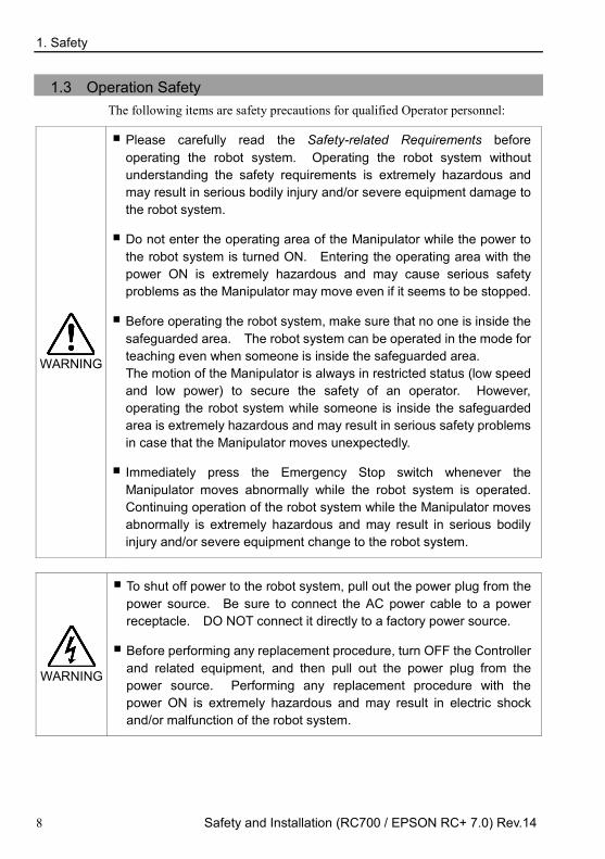
1.3 Operation Safety The following items are safety precautions for qualified Operator personnel:
WARNING
Please carefully read the Safety-related Requirements before operating the robot system. Operating the robot system without understanding the safety requirements is extremely hazardous and may result in serious bodily injury and/or severe equipment damage to the robot system.
Do not enter the operating area of the Manipulator while the power to the robot system is turned ON. Entering the operating area with the power ON is extremely hazardous and may cause serious safety problems as the Manipulator may move even if it seems to be stopped.
Before operating the robot system, make sure that no one is inside the safeguarded area. The robot system can be operated in the mode for teaching even when someone is inside the safeguarded area. The motion of the Manipulator is always in restricted status (low speed and low power) to secure the safety of an operator. However, operating the robot system while someone is inside the safeguarded area is extremely hazardous and may result in serious safety problems in case that the Manipulator moves unexpectedly.
Immediately press the Emergency Stop switch whenever the Manipulator moves abnormally while the robot system is operated. Continuing operation of the robot system while the Manipulator moves abnormally is extremely hazardous and may result in serious bodily injury and/or severe equipment change to the robot system.
WARNING
To shut off power to the robot system, pull out the power plug from the power source. Be sure to connect the AC power cable to a power receptacle. DO NOT connect it directly to a factory power source.
Before performing any replacement procedure, turn OFF the Controller and related equipment, and then pull out the power plug from the power source. Performing any replacement procedure with the power ON is extremely hazardous and may result in electric shock and/or malfunction of the robot system.

1. Safety
Safety and Installation (RC700 / EPSON RC+ 7.0) Rev.14 9
WARNING
Do not insert or pull out the motor connectors while the power to the robot system is turned ON. Inserting or pulling out the motor connectors with the power ON is extremely hazardous and may result in serious bodily injury as the Manipulator may move abnormally, and also may result in electric shock and/or malfunction of the robot system.
CAUTION
Whenever possible, only one person should operate the robot system. If it is necessary to operate the robot system with more than one person, ensure that all people involved communicate with each other as to what they are doing and take all necessary safety precautions.
SCARA Robot: Joint #1, #2, and #4: If the joints are operated repeatedly with the operating angle less than 5 degrees, they may get damaged early because the bearings are likely to cause oil film shortage in such situation. To prevent early breakdown, move the joints larger than 50 degrees for about five to ten times a day.
Joint #3: If the up-and-down motion of the hand is less than 10 mm, move the joint a half of the maximum stroke for five to ten times a day.
Vertical 6-axis Robot: If the joints are operated repeatedly with the operating angle less than 5 degrees, they may get damaged early because the bearings are likely to cause oil film shortage in such situation. To prevent early breakdown, move the joints larger than 30 degrees for about five to ten times a day.
Oscillation (resonance) may occur continuously in low speed Manipulator motion (Speed: approx. 5 to 20%) depending on combination of Arm orientation and end effector load. Oscillation arises from natural oscillation frequency of the Arm and can be controlled by following measures.
Changing Manipulator speed
Changing the teach points
Changing the end effector load
1. Safety
10 Safety and Installation (RC700 / EPSON RC+ 7.0) Rev.14
CAUTION
Whenever possible, only one person should operate the robot system. If it is necessary to operate the robot system with more than one person, ensure that all people involved communicate with each other as to what they are doing and take all necessary safety precautions.

1. Safety
Safety and Installation (RC700 / EPSON RC+ 7.0) Rev.14 11
1.3.1 Safety-related Requirements Specific tolerances and operating conditions for safety are contained in the manuals for the robot, controller and other devices. Be sure to read those manuals as well.
For the installation and operation of the robot system, be sure to comply with the applicable local and national regulations.
Robot system safety standards and other examples are given in this chapter. To ensure that safety measures are satisfied, also refer to these standards.
(Note: The following is a partial list of the necessary safety standards.)
EN ISO 10218-1 Robots and robotic devices -- Safety requirements for industrial robots -- Part 1: Robots
EN ISO 10218-2 Robots and robotic devices -- Safety requirements for industrial robots -- Part 2: Robot systems and integration
ANSI/RIA R15.06 American National Standard for Industrial Robots and Robot Systems -- Safety Requirements
EN ISO 12100 Safety of machinery -- General principles for design -- Risk assessment and risk reduction
EN ISO 13849-1 Safety of machinery -- Safety-related parts of control systems -- Part 1: General principles for design
EN ISO 13850 Safety of machinery -- Emergency stop -- Principles for design EN ISO 13855 Safety of machinery -- Positioning of safeguards with respect to the
approach speeds of parts of the human body. EN ISO 13857 Safety of machinery -- Safety distances to prevent hazard zones being
reached by upper and lower limbs. ISO 14120 EN 953
Safety of machinery -- Guards -- General requirements for the design and construction of fixed and movable guards
IEC 60204-1 EN 60204-1
Safety of machinery -- Electrical equipment of machines -- Part 1: General requirements
CISPR11 EN55011
Industrial, scientific and medical (ISM) radio-frequency equipment -- Electromagnetic disturbance characteristics -- Limits and methods of measurement
IEC 61000-6-2 EN 61000-6-2
Electromagnetic compatibility (EMC) -- Part 6-2: Generic standards -- Immunity for industrial environments
RC700-A / RC700DU-A UL specification Compatibility assessment of the UL-compliant model is performed according to the following standards.
UL1740 (2007 Edition) ANSI/RIA R15.06-2012 NFPA 79 (2015 Edition) CSA/CAN Z434-14 ISO 138491-1:2015 IEC62061:2005
1. Safety
12 Safety and Installation (RC700 / EPSON RC+ 7.0) Rev.14
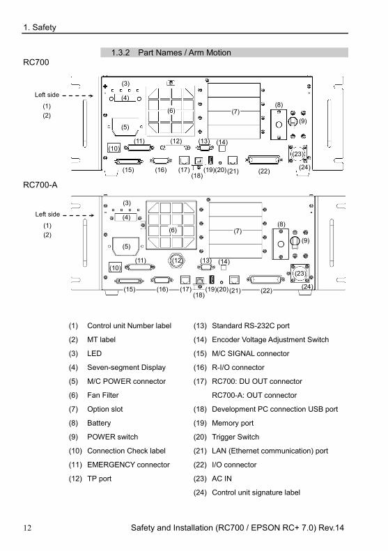
1.3.2 Part Names / Arm Motion RC700
Left side
(3)
(4) (1)
(2)
(5)
(6) (7) (8)
(9)
(10) (11) (12) (13) (14)
(15) (16) (17) (18)
(19)(20) (21) (22)
(23)
(24)
RC700-A
Left side
(3)
(4) (1)
(2)
(5)
(6) (7) (8)
(9)
(10) (11) (12) (13) (14)
(15) (16) (17) (18)
(19)(20) (21) (22)
(23)
(24)
(1) Control unit Number label
(2) MT label
(3) LED
(4) Seven-segment Display
(5) M/C POWER connector
(6) Fan Filter
(7) Option slot
(8) Battery
(9) POWER switch
(10) Connection Check label
(11) EMERGENCY connector
(12) TP port
(13) Standard RS-232C port
(14) Encoder Voltage Adjustment Switch
(15) M/C SIGNAL connector
(16) R-I/O connector
(17) RC700: DU OUT connector
RC700-A: OUT connector
(18) Development PC connection USB port
(19) Memory port
(20) Trigger Switch
(21) LAN (Ethernet communication) port
(22) I/O connector
(23) AC IN
(24) Control unit signature label

1. Safety
Safety and Installation (RC700 / EPSON RC+ 7.0) Rev.14 13
RC700-A-UL
(25)
UL-compliant Controller (RC700-A-UL):
This model has (25) lockout mechanism. For the lockout procedure, refer to the following section.
1.2.2 Designing a Safe Robot System - Disabling Power to the System using lockout / tagout

1. Safety
14 Safety and Installation (RC700 / EPSON RC+ 7.0) Rev.14
RC700DU / RC700DU-A
Left side
(3)
(4)
(1) (2)
(5) (6)
(7)
(8) (9)
(10) (11) (12)(13) (14) (15)
(16)
(17)
(1) Drive Unit Number label
(2) MT label
(3) LED
(4) M/C POWER connector
(5) Fan Filter
(6) POWER switch
(7) Connection Check label
(8) EMERGENCY connector
(9) Encoder Voltage Adjustment Switch
(10) M/C SIGNAL connector
(11) R-I/O connector
(12) RC700: DU OUT connector
RC700-A: OUT connector
(13) RC700: DU IN connector
RC700-A: IN connector
(14) RC700DU No. setup switch
(15) I/O connector
(16) AC IN
(17) Drive unit signature label

1. Safety
Safety and Installation (RC700 / EPSON RC+ 7.0) Rev.14 15
G1
The motion range of each arm is shown in the figure below. Take all necessary safety precautions.
Signal cable
Power cable
Fitting (black or blue)* for ø4 mm pneumatic tube
User connector (9-pin D-sub connector)
LED
MT label (only for special order)
Face plate (Manipulator serial No.)
CE label
Joint #3 Brake release switch
Base
Shaft
User connector (15-pin D-sub connector)
Fitting (black or blue)* for ø6 mm pneumatic tube
Fittings (white) for ø6 mm pneumatic tube
UR label
Cable
User connector (9-pin D-sub connector)
User connector (15-pin D-sub connector)
Fittings (white) for ø6 mm pneumatic tube
Fitting (black or blue)* for ø6 mm pneumatic tube Fitting (black or blue)*
for ø4 mm pneumatic tube
* Color differs depending on the shipment time
Joint #2 (rotating)
Joint #1 (rotating)
Joint #3 (up/down)
Joint #4 (rotating)
Arm #1
Arm #2

1. Safety
16 Safety and Installation (RC700 / EPSON RC+ 7.0) Rev.14
When the system is placed in emergency mode, push the arm or joint of the Manipulator by hand as shown below:
Arm #1 Push the arm by hand.
Arm #2 Push the arm by hand.
Joint #3 The joint cannot be moved up/down by hand until the
electromagnetic brake applied to the joint has been released.
Move the joint up/down while pressing the brake release switch.
Joint #4 Rotate the shaft by hand.
When the brake release switch is pressed in emergency mode, the brake for Joint #3 is released. Be careful of the shaft while the brake release switch is pressed because the shaft may be lowered by the weight of an end effector.
NOTE

1. Safety
Safety and Installation (RC700 / EPSON RC+ 7.0) Rev.14 17
G3
The motion range of each arm is shown in the figure below. Take all necessary safety precautions.
CE label
+ −
+ −
+
−
+
−
UR label
Joint #3 Brake release switch
Joint #1 (rotating)
Joint #2 (rotating)
Joint #3 (up/down)
Joint #4 (rotating)
Arm #1
Arm #2
Base
Shaft
MT label (only for special order)
Face plate (Manipulator serial No.)
Signal cable Power cable
Fitting (black or blue)* for ø4 mm pneumatic tube
Fittings (black or blue)* for ø6 mm
pneumatic tube
Fittings (white) for ø6 mm
pneumatic tube
User connector (15-pin D-sub connector)
LED lamp
* Color differs depending on the shipment time

1. Safety
18 Safety and Installation (RC700 / EPSON RC+ 7.0) Rev.14
When the system is placed in emergency mode, push the arm or joint of the Manipulator by hand as shown below:
Arm #1 Push the arm by hand.
Arm #2 Push the arm by hand.
Joint #3 The joint cannot be moved up/down by hand until the
electromagnetic brake applied to the joint has been released.
Move the joint up/down while pressing the brake release switch.
Joint #4 Rotate the shaft by hand.
When the brake release switch is pressed in emergency mode, the brake for Joint #3 is released.
Be careful of the shaft while the brake release switch is pressed because the shaft may be lowered by the weight of an end effector.
NOTE
1. Safety
Safety and Installation (RC700 / EPSON RC+ 7.0) Rev.14 19
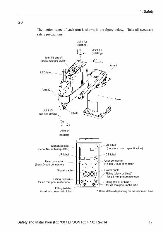
G6
The motion range of each arm is shown in the figure below. Take all necessary safety precautions.
MT label (only for custom specification)
Signature label (Serial No. of Manipulator)
Signal cable Power cable Fitting (black or blue)* for ø 6 mm pneumatic tube
User connector (15-pin D-sub connector)
User connector (9-pin D-sub connector)
CE label
Joint #3 and #4 brake release switch
Joint #1 (rotating)
Joint #2 (rotating)
Joint #3 (up and down)
Joint #4 (rotating)
Arm #1
Arm #2
Base
+ −
+ −
+
−
+
−
Shaft
Fitting (black or blue)* for ø 4 mm pneumatic tube
Fitting (white) for ø 6 mm pneumatic tube
Fitting (white) for ø 4 mm pneumatic tube
LED lamp
UR label
* Color differs depending on the shipment time

1. Safety
20 Safety and Installation (RC700 / EPSON RC+ 7.0) Rev.14
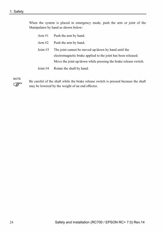
When the system is placed in emergency mode, push the arm or joint of the Manipulator by hand as shown below:
Arm #1 Push the arm by hand.
Arm #2 Push the arm by hand.
Joint #3 The joint cannot be moved up/down by hand until the
electromagnetic brake applied to the joint has been released.
Move the joint up/down while pressing the brake release switch.
Joint #4 For G6-**1**,
Rotate the shaft by hand.
For G6-**3**,
The shaft cannot be rotated by hand until the electromagnetic
brake applied to the shaft has been released. Move the shaft
while pressing the brake release switch.
The brake release switch affects both Joints #3 and #4. When the brake release switch is pressed in emergency mode, the brakes for both Joints #3 and #4 are released simultaneously. (For G6-**1**, Joint #4 has no brake on it.)
Be careful of the shaft falling and rotating while the brake release switch is pressed because the shaft may be lowered by the weight of an end effector.
NOTE

1. Safety
Safety and Installation (RC700 / EPSON RC+ 7.0) Rev.14 21
G10/G20
The motion range of each arm is shown in the figure below. Take all necessary
safety precautions.
+
−
+ −
+ −
+
−
Joint #3 and #4 brake release switch
Joint #1 (rotating)
Joint #2 (rotating)
Joint #3 (up and down)
Joint #4 (rotating)
Arm #1
Arm #2
Base
Shaft
MT label (only for custom specification) Signature label
(Serial No. of Manipulator)
Signal cable Power cable
Fitting (black or blue)* for ø 6 mm pneumatic tube
User connector (15-pin D-sub connector)
User connector (9-pin D-sub connector)
CE label
Fitting (black or blue)* for ø 4 mm pneumatic tube
Fitting (white) for ø 6 mm pneumatic tube
Fitting (white) for ø 4 mm pneumatic tube
LED lamp
UR label
* Color differs depending on the shipment time

1. Safety
22 Safety and Installation (RC700 / EPSON RC+ 7.0) Rev.14
When the system is placed in emergency mode, push the arm or joint of the
Manipulator by hand as shown below:
Arm #1 Push the arm by hand.
Arm #2 Push the arm by hand.
Joint #3 The joint cannot be moved up/down by hand until the electromagnetic brake applied to the joint has been released. Move the joint up/down while pressing the brake release switch.
Joint #4 The shaft cannot be rotated by hand until the electromagnetic brake applied to the shaft has been released. Move the shaft while pressing the brake release switch.
The brake release switch affects both Joints #3 and #4. When the brake release
switch is pressed in emergency mode, the brakes for both Joints #3 and #4 are
released simultaneously.
Be careful of the shaft falling and rotating while the brake release switch is pressed
because the shaft may be lowered by the weight of an end effector.
NOTE

1. Safety
Safety and Installation (RC700 / EPSON RC+ 7.0) Rev.14 23
RS3
The motion range of each arm is shown in the figure below. Take all necessary safety precautions.
MT label (only for custom specification)
Signature label
(Serial No. of Manipulator)
Signal Cable Power Cable
User Connector (15-pin D-sub Connector)
CE label
Joint #3 and #4 brake release switch
Joint #2 (rotating)
Joint #1 (rotating)
Joint #3 (up and down)
Joint #4 (rotating)
Arm #1
Arm #2
Base +
−
+
−
+
−
+
−
Shaft
Base
Arm #1 Arm #2
Power Cable Signal Cable
Fitting (white) for ø 6 mm pneumatic tube
Fitting (white) for ø4 mm pneumatic tube
Fitting (black or blue)* for ø 6 mm pneumatic tube
User Connector (15-pin D-sub Connector)
Fitting (white) for ø 6 mm pneumatic tube
UR label (only for UL specification)
Fitting (black or blue)* for ø 6 mm pneumatic tube
Fitting (white) for ø4 mm pneumatic tube
* Color differs depending on the shipment time
1. Safety
24 Safety and Installation (RC700 / EPSON RC+ 7.0) Rev.14
When the system is placed in emergency mode, push the arm or joint of the Manipulator by hand as shown below:
Arm #1 Push the arm by hand.
Arm #2 Push the arm by hand.
Joint #3 The joint cannot be moved up/down by hand until the
electromagnetic brake applied to the joint has been released.
Move the joint up/down while pressing the brake release switch.
Joint #4 Rotate the shaft by hand.
Be careful of the shaft while the brake release switch is pressed because the shaft may be lowered by the weight of an end effector.
NOTE

1. Safety
Safety and Installation (RC700 / EPSON RC+ 7.0) Rev.14 25
RS4
The motion range of each arm is shown in the figure below. Take all necessary safety precautions.
Joint #2 (rotating)
Joint #1 (rotating)
Joint #4 (rotating)
Arm #1
Arm #2
Base
+ −
+ −
+
−
+
−
Shaft
Base
Arm #1 Arm #2
LED lamp
Signal Cable Power Cable
User Connector (15-pin D-sub Connector)
Fitting (white) for ø 6 mm pneumatic tube
Fitting (black or blue)* for ø 6 mm pneumatic tube
Fitting (white) for ø4 mm pneumatic tube
Signal Cable
Power Cable
Joint #3 (up and down)
User Connector (15-pin D-sub Connector)
Joint #3 and #4 brake release switch
Fitting (white) for ø 6 mm pneumatic tube
Fitting (white) for ø4 mm pneumatic tube
Fitting (black or blue)*
for ø 6 mm pneumatic tube
Signature label (Serial No. of Manipulator)
CE label
* Color differs depending on the shipment time
UR label (only for UL specificatio

1. Safety
26 Safety and Installation (RC700 / EPSON RC+ 7.0) Rev.14
When the system is placed in emergency mode, push the arm or joint of the Manipulator by hand as shown below:
Arm #1 Push the arm by hand.
Arm #2 Push the arm by hand.
Joint #3 The joint cannot be moved up/down by hand until the
electromagnetic brake applied to the joint has been released.
Move the joint up/down while pressing the brake release switch.
Joint #4 Rotate the shaft by hand.
Be careful of the shaft while the brake release switch is pressed because the shaft may be lowered by the weight of an end effector.
NOTE

1. Safety
Safety and Installation (RC700 / EPSON RC+ 7.0) Rev.14 27
C4
The motion range of each arm is shown in the figure below. Take all necessary safety precautions.
Joint #1
Base
Arm #1 (Lower Arm)
Arm #2
Arm #4
Joint #6 Joint #3
Joint #4
Joint #5
Arm #6
Joint #2
Arm #5
LED Lamp This lamp lights up while the motors are ON.
Upper Arm (Arms #3 to #6)
Joint Motion
Joint #1 : The whole Manipulator revolves.
Joint #2 : The lower arm swings.
Joint #3 : The upper arm swings.
Joint #4 : The wrist revolves.
Joint #5 : The wrist swings.
Joint #6 : The hand rotates.
Arm #3
When the LED lamp is lighting or the controller power is on, the current is being applied to the manipulator. (The LED lamp may not be seen depending on the Manipulator’s posture. Be very careful.) Performing any work with the power ON is extremely hazardous and it may result in electric shock and/or improper function of the robot system. Make sure to turn OFF the controller power before the maintenance work.
NOTE

1. Safety
28 Safety and Installation (RC700 / EPSON RC+ 7.0) Rev.14
Signal cable Power cable
User cable connector (9-pin D-sub connector)
Fitting for ø 4 mm pneumatic tube
Standard-model / Clean-room model Cover Exhaust port For ø8 mm pneumatic tube
White
Blue
MT label (only for custom
specification)
Signature label (Serial No. of Manipulator)
CE label (only for CE specification)
UR label (only for UL specification)

1. Safety
Safety and Installation (RC700 / EPSON RC+ 7.0) Rev.14 29
C8 The motion range of each arm is shown in the figure below. Take all necessary safety precautions.
Joint #1
Base
Arm #1 (Lower Arm)
Arm #2
Arm #4
Joint #6
Joint #3
Joint #4
Joint #5
Arm #6
Joint #2
Arm #5
LED Lamp This lamp lights up while the motors are ON.
Upper Arm (Arms #3 to #6)
Arm #3
J1+
J1-
J2- J2+
J3+
J3-
J4-
J4+
J5+
J5-
J6-
J6+
Joint Motion
Joint #1 : The whole Manipulator revolves.
Joint #2 : The lower arm swings.
Joint #3 : The upper arm swings.
Joint #4 : The wrist revolves.
Joint #5 : The wrist swings.
Joint #6 : The hand rotates.
(Figure: C8-A701* (C8))
When the LED lamp is lighting or the controller power is on, the current is being applied to the manipulator. (The LED lamp may not be seen depending on the Manipulator’s posture. Be very careful.) Performing any work with the power ON is extremely hazardous and it may result in electric shock and/or improper function of the robot system. Make sure to turn OFF the controller power before the maintenance work.
NOTE

1. Safety
30 Safety and Installation (RC700 / EPSON RC+ 7.0) Rev.14
Cable backward model
Power cable
Signal cable
User cable connector (15-pin D-sub connector)
For ø6 mm pneumatic tubes (Air1, Air2)
F-sensor cable connector
Ethernet cable connector
Standard-model : Cover
Clean-room model : Exhaust port For ø12 mm pneumatic tube
Cable downward model
Power cable
Signal cable
User cable connector (15-pin D-sub connector)
For ø6 mm pneumatic tubes (Air1, Air2)
F sensor cable connector
Ethernet cable connector
Standard-model : Cover
Clean-room model : Exhaust port For ø12 mm pneumatic tube
Cable backward model / Cable downward model
MT label (only for custom
specification)
Signature label (Serial No. of Manipulator)
CE label (only for CE specification)
UR label (only for UL specification)
KC/KCs label
Bolt hole M5 (for grounding)
(Figure: Cable backward model)

1. Safety
Safety and Installation (RC700 / EPSON RC+ 7.0) Rev.14 31
N2
Base
Arm #1
Joint #2
Arm #2
J2+
J2-
Joint #1
Joint #3
Arm #3
Joint #4
Arm #4
Joint #5
Arm #5
Joint #6
Arm #6
J1+
J1- J3-
J3+
J4-
J4+
J5+
J5-
J6+ J6-
LED Lamp
Ethernet 1 Power cable
Signal cable
User cable connector
Brake release connector
Ethernet cable connectors
One-touch fittings for ø6 mm pneumatic tubes Air 1 Air 2
One-touch fittings for ø6 mm pneumatic
Ethernet 2
1 2
Ethernet 1 Ethernet cable connectors
Ethernet 2
User connector
One-touch fittings for ø6 mm pneumatic tubes Air 1 Air 2
When the LED lamp is lighting or the controller power is on, the current is being applied to the manipulator. (The LED lamp may not be seen depending on the Manipulator’s posture. Be very careful.) Performing any work with the power ON is extremely hazardous and it may result in electric shock and/or improper function of the robot system. Make sure to turn OFF the controller power before the maintenance work.
NOTE

1. Safety
32 Safety and Installation (RC700 / EPSON RC+ 7.0) Rev.14
X5 The operation varies with different module combination. For details, refer to the EZ Module X5 Series manual.

1. Safety
Safety and Installation (RC700 / EPSON RC+ 7.0) Rev.14 33
1.3.3 Operation Modes
The robot system has three operation modes: TEACH, AUTO, and TEST modes.
TEACH mode
This mode enables point data teaching and checking close from the Robot using the Teach Pendant. Robot operates in Low power status.
AUTO mode This mode enables automatic operation (program execution) of the Robot system at the factory. In this mode, robot operation and program execution are not allowed when the safety door is open.
TEST mode (T1) This mode enables program verification while the Enable
Switch is held down and the safeguard (including the safety door) is open. This is a low speed program verification function (T1: manual deceleration mode) which is defined in Safety Standards. In this mode, the specified Function can be executed with multi-task / single-task, multi-manipulator / single-manipulator at low speed.
(T2) RC700-A
option TP3 only
This mode enables program verification while the Enable Switch is held down and the safeguard (including the safety door) is open. Unlike the TEST/T1, the program verification in a high speed is available in this mode. In this mode, the specified Function can be executed with multi-task / single-task, multi-manipulator / single-manipulator at high speed.
T2 mode cannot be used on RC700-A Controllers complying with the UL standards.
NOTE

1. Safety
34 Safety and Installation (RC700 / EPSON RC+ 7.0) Rev.14
1.4 Maintenance Safety Please read this section, Maintenance of the Manipulator manual, Maintenance of the Controller manual, and other related manuals carefully to understand safe maintenance procedures before performing any maintenance. Only authorized personnel who have taken the safety training should be allowed to maintain the robot system. The safety training is the program for the industrial robot operator that follows the laws and regulations of each nation. The personnel who have taken the safety training acquire knowledge of industrial robots (operations, teaching, etc.), knowledge of inspections, and knowledge of related rules/regulations. Only personnel who have completed the robot system-training and maintenance-training classes held by the manufacturer, dealer, or locally-incorporated company should be allowed to maintain the robot system.
WARNING
Do not remove any parts that are not covered in this manual. Follow the maintenance procedure strictly as described in this manual, Maintenance of the Manipulator manual, and Maintenance of the Controller manual. Improper removal of parts or improper maintenance may not only cause improper function of the robot system but also serious safety problems.
Keep away from the Manipulator while the power is ON if you have not taken the training courses. Do not enter the operating area while the power is ON. Entering the operating area with the power ON is extremely hazardous and may cause serious safety problems as the Manipulator may move even though it seems to be stopped.
When you check the operation of the Manipulator after replacing parts, be sure to check it while you are outside of the safeguarded area. Checking the operation of the Manipulator while you are inside of the safeguarded area may cause serious safety problems as the Manipulator may move unexpectedly.
Before operating the robot system, make sure that both the Emergency Stop switches and safeguard switches function properly. Operating the robot system when the switches do not function properly is extremely hazardous and may result in serious bodily injury and/or serious damage to the robot system as the switches cannot fulfill their intended functions in an emergency.

1. Safety
Safety and Installation (RC700 / EPSON RC+ 7.0) Rev.14 35
WARNING
Be sure to connect the AC power cable to a power receptacle. DO NOT connect it directly to a factory power source. To shut off power to the robot system, pull out the power plug from the power source. Performing any work while connecting the AC power cable to a factory power source is extremely hazardous and may result in electric shock and/or malfunction of the robot system.
Before performing any replacement procedure, turn OFF the Controller and related equipment, and then pull out the power plug from the power source. Performing any replacement procedure with the power ON is extremely hazardous and may result in electric shock and/or malfunction of the robot system.
Be sure to connect the cables properly. Do not allow unnecessary strain on the cables. (Do not put heavy objects on the cables. Do not bend or pull the cables forcibly.) The unnecessary strain on the cables may result in damage to the cables, disconnection, and/or contact failure. Damaged cables, disconnection, or contact failure is extremely hazardous and may result in electric shock and/or improper function of the robot system.
CAUTION
Carefully use alcohol, liquid gasket, and adhesive following respective instructions and also instructions below. Careless use of alcohol, liquid gasket, or adhesive may cause a fire and/or safety problems.
- Never put alcohol, liquid gasket, or adhesive close to fire. - Use alcohol, liquid gasket, or adhesive while ventilating the room. - Wear protective gear including a mask, protective goggles, and
oil-resistant gloves. - If alcohol, liquid gasket, or adhesive gets on your skin, wash the area
thoroughly with soap and water. - If alcohol, liquid gasket, or adhesive gets into your eyes or mouth,
flush your eyes or wash out your mouth with clean water thoroughly, and then see a doctor immediately.

1. Safety
36 Safety and Installation (RC700 / EPSON RC+ 7.0) Rev.14
CAUTION
Wear protective gear including a mask, protective goggles, and oil-resistant gloves during grease up. If grease gets into your eyes, mouth, or on your skin, follow the instructions below.
If grease gets into your eyes: Flush them thoroughly with clean water, and then see a doctor immediately.
If grease gets into your mouth: If swallowed, do not induce vomiting. See a doctor immediately. If grease just gets into your mouth, wash out your mouth with water thoroughly.
If grease gets on your skin: Wash the area thoroughly with soap and water.
Manipulator may be warmed up due to motor heat or similar causes. Do not touch the Manipulator until temperature falls. Also, make sure the temperature of the Manipulator falls and you do not feel hot when you touch it. Then perform teaching or maintenance.

1. Safety
Safety and Installation (RC700 / EPSON RC+ 7.0) Rev.14 37
1.5 Emergency Stop G1, G3, G6, G10, G20, RS, C4, C8, N2 series
If the Manipulator moves abnormally during operation, immediately press the Emergency Stop switch. Pressing the Emergency Stop switch immediately changes the manipulator to deceleration motion and stops it at the maximum deceleration speed.
However, avoid pressing the Emergency Stop switch unnecessarily while the Manipulator is running normally. Pressing the Emergency Stop switch locks the brake and it may cause wear on the friction plate of the brake, resulting in the short life of the brake.
Normal brake life cycle: About 2 years (when the brakes are used 100 times/day) To place the system in emergency mode during normal operation, press the Emergency Stop switch when the Manipulator is not moving. Refer to the Controller manual for instructions on how to wire the Emergency Stop switch circuit. Do not turn OFF the Controller while the Manipulator is operating. If you attempt to stop the Manipulator in emergency situations, make sure to stop the Manipulator using the E-STOP of the Controller. If the Manipulator is stopped by turning OFF the Controller while it is operating, following problems may occur. Reduction of the life and damage of the reduction gear unit Position gap at the joints In addition, if the Controller was forced to be turned OFF by blackouts and the like while the Manipulator is operating, make sure to check the following points after power restoration. Whether or not the reduction gear is damaged Whether or not the joints are in their proper positions If there is a position gap, perform calibration by referring to the Maintenance: Calibration in the Manipulator manual. Manipulator manuals contain information on the Emergency Stop. Please also read the descriptions in the manual and use the robot system properly.

1. Safety
38 Safety and Installation (RC700 / EPSON RC+ 7.0) Rev.14
Before using the Emergency Stop switch, be aware of the followings. - The Emergency Stop (E-STOP) switch should be used to stop the
Manipulator only in case of emergencies. - To stop the Manipulator operating the program except in emergency, use
Pause (halt) or STOP (program stop) commands Pause and STOP commands do not turn OFF the motors. Therefore, the brake does not function.
- For the Safeguard system, do not use the circuit for E-STOP. For details of the Safeguard system, refer to the following manuals.
EPSON RC+ User’s Guide 2. Safety - Installation and Design Precautions - Safeguard System
Safety and Installation 2.6 Connection to EMERGENCY Connector To check brake problems, refer to the following manuals. Manipulator Manual Maintenance 2.1.2 Inspection Point - Inspection While the Power is ON (Manipulator is operating) Safety and Installation 5.1.1 Manipulator - Inspection While the Power is ON (Manipulator is operating)

1. Safety
Safety and Installation (RC700 / EPSON RC+ 7.0) Rev.14 39
X5 series If the Manipulator moves abnormally during operation, immediately press the Emergency Stop switch. Pressing the Emergency Stop switch immediately changes the manipulator to deceleration motion and stops it at the maximum deceleration speed. However, avoid pressing the Emergency Stop switch unnecessarily while the Manipulator is running normally. Otherwise, the Manipulator may hit the peripheral equipment since the operating trajectory until the robot system stops is different from that in normal operation. Do not press the Emergency Stop switch unnecessarily while the Manipulator is operating. Pressing the switch during operation makes the brakes work. This will shorten the life of the brakes due to the worn friction plates.
Normal brake life cycle: About 2 years (when the brakes are used 100 times/day)
Also, the Emergency Stop during operation applies impact on the reduction gear unit, and it may result in the short life of the reduction gear unit. To place the robot system in emergency mode during normal operation, press the Emergency Stop switch while the Manipulator is not moving. Refer to the Robot Controller manual for instructions on how to wire the Emergency Stop switch circuit.
When the Manipulator is stopped by the emergency stop function (the electric current for the motor is cut off), the J1 and J2 axes may overrun a maximum of 150 mm from their servo motion target points. Therefore, design the layout of the robot system so that the end effector does not collide with peripheral equipment.
When the Manipulator is stopped by the emergency stop while it is moving with large load being applied, an error may occur. If the error occurs, reset it by the Reset command. Example: If the Emergency Stop switch is pressed while the RH module is
carrying an 80 kg workpiece. The following error occurs:
5040: Motor torque output failure in high power state.
Do not turn OFF the Controller while the Manipulator is operating. If you attempt to stop the Manipulator in emergency situations such as “Safeguard Open”, make sure to stop the Manipulator using the Emergency Stop switch of the Controller. If the Manipulator is stopped by turning OFF the Controller while it is operating, the following problems may occur. Reduction of the life and damage of the reduction gear unit Position gap at the joints
NOTE

1. Safety
40 Safety and Installation (RC700 / EPSON RC+ 7.0) Rev.14
In addition, if the Controller was forced to be turned OFF by blackouts and the like while the Manipulator is operating, make sure to check the following points after power restoration. Whether or not the reduction gear is damaged Whether or not the joints are in their proper positions If there is a position gap, perform calibration by referring to the 4.13 Calibration in this manual. Before using the Emergency Stop switch, be aware of the followings. The Emergency Stop (E-STOP) switch should be used to stop the Manipulator only in case of emergencies. Before using the Emergency Stop switch, be aware of the followings.
- The Emergency Stop (E-STOP) switch should be used to stop the Manipulator only in case of emergencies.
- To stop the Manipulator operating the program except in emergency, use Pause (halt) or STOP (program stop) commands Pause and STOP commands do not turn OFF the motors. Therefore, the brake does not function.
- For the Safeguard system, do not use the circuit for E-STOP. For details of the Safeguard system, refer to the following manuals.
EPSON RC+ User’s Guide 2. Safety - Installation and Design Precautions - Safeguard System
Safety and Installation 2.6 Connection to EMERGENCY Connector
To check brake problems, refer to the following manuals.
Safety and Installation 5.1.1 Manipulator - Inspection While the Power is ON (Manipulator is operating)

1. Safety
Safety and Installation (RC700 / EPSON RC+ 7.0) Rev.14 41
1.5.1 Free running distance in emergency The Manipulator in operation cannot stop immediately after the Emergency Stop switch is pressed. However, remember that the values vary depending on following conditions:
Hand weight WEIGHT Setting ACCEL Setting Workpiece weight SPEED Setting Posture etc.
Approximate time and distance of the free running are as follow:
G1 Conditions for measurement
Accel setting 100 Speed setting 100 Load [kg] 1 Weight setting 1
Joint #1
Stop point
Point where the emergency stop signal is input
Target point
Start point of operation
Joint #2
Controller RC700-A
Manipulator G1-171*, G1-171*Z G1-221*, G1-221*Z Free running time
Joint #1 + Joint #2 [s] 0.17 0.18 Joint #3 [s] 0.13
Free running angle
Joint #1 [deg] 22 28 Joint #2 [deg] 19 20 Joint #1 + Joint #2 [deg] 41 48
Free running distance Joint #3 [mm] 48

1. Safety
42 Safety and Installation (RC700 / EPSON RC+ 7.0) Rev.14
G3 Conditions for Measurement
Accel Setting 100 Speed Setting 100 Load [kg] 3 Weight Setting 3
Joint #1
Point where the emergency stop signal is input
Start point of operation
Target point
Stop point Joint #2
Controller RC700-A
Manipulator G3-25*** G3-30*** G3-35*** Free running time
Joint #1 + Joint #2 [s] 0.3 0.2 0.3 Joint #3 [s] 0.2 0.2 0.2
Free running angle
Joint #1 [deg] 20 20 35 Joint #2 [deg] 20 20 25 Joint #1 + Joint #2 [deg] 40 40 60
Free running distance Joint #3 [mm] 60 60 60

1. Safety
Safety and Installation (RC700 / EPSON RC+ 7.0) Rev.14 43
G6 Conditions for Measurement
Accel Setting 100 Speed Setting 100 Load [kg] 6 Weight Setting 6
Joint #1 Point where the emergency stop signal is input
Start point of operation
Target point
Stop point
Joint #2
Controller RC700-A
Manipulator G6-45*** G6-55*** G6-65*** Free running time
Joint #1 + Joint #2 [s] 0.5 0.5 0.5 Joint #3 [s] 0.4 0.4 0.4
Free running angle
Joint #1 [deg] 35 30 35 Joint #2 [deg] 70 55 70 Joint #1 + Joint #2 [deg] 105 85 105
Free running distance
Joint #3 G6-**1** [mm] G6-**3** 95 95 95
1. Safety
44 Safety and Installation (RC700 / EPSON RC+ 7.0) Rev.14
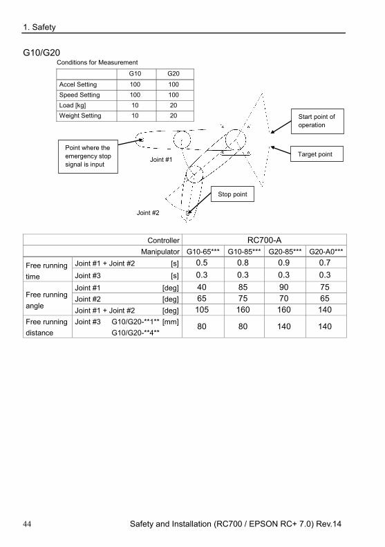
G10/G20 Conditions for Measurement
G10 G20
Accel Setting 100 100 Speed Setting 100 100 Load [kg] 10 20 Weight Setting 10 20
Joint #1
Start point of operation
Target point
Stop point
Joint #2
Point where the emergency stop signal is input
Controller RC700-A Manipulator G10-65*** G10-85*** G20-85*** G20-A0***
Free running time
Joint #1 + Joint #2 [s] 0.5 0.8 0.9 0.7 Joint #3 [s] 0.3 0.3 0.3 0.3
Free running angle
Joint #1 [deg] 40 85 90 75 Joint #2 [deg] 65 75 70 65 Joint #1 + Joint #2 [deg] 105 160 160 140
Free running distance
Joint #3 G10/G20-**1** [mm] G10/G20-**4**
80 80 140 140
1. Safety
Safety and Installation (RC700 / EPSON RC+ 7.0) Rev.14 45
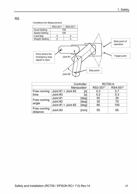
RS Conditions for Measurement
RS3-351* RS4-551* Accel Setting 100 Speed Setting 100 Load [kg] 3 4 Weight Setting 3 4
Joint #1 Point where the emergency stop signal is input
Start point of operation
Target point
Stop point Joint #2
Controller RC700-A
Manipulator RS3-351* RS4-551* Free running time
Joint #1 + Joint #2 [s] 0.3 0.7 Joint #3 [s] 0.2 0.3
Free running angle
Joint #1 [deg] 50 30 Joint #2 [deg] 30 70 Joint #1 + Joint #2 [deg] 80 100
Free running distance Joint #3 [mm] 55 65

1. Safety
46 Safety and Installation (RC700 / EPSON RC+ 7.0) Rev.14
C4 Conditions of Measurement
C4 series ACCEL Setting 100 SPEED Setting 100 Load [kg] 4 WEIGHT Setting 4
Robot controller RC700 / RC700-A
Manipulator C4-A601** C4-A901**
Free running time [s]
Arm #1 0.4 0.3 Arm #2 0.4 0.4 Arm #3 0.4 0.5 Arm #4 0.3 Arm #5 0.4 Arm #6 0.3
Free running angle [deg]
Arm #1 85 60 Arm #2 60 65 Arm #3 55 55 Arm #4 40 Arm #5 40 Arm #6 25

1. Safety
Safety and Installation (RC700 / EPSON RC+ 7.0) Rev.14 47
C8 Conditions of Measurement C8 series ACCEL Setting 100 SPEED Setting 100 Load [kg] 8 WEIGHT Setting 8
Robot controller RC700-A
Manipulator C8-A701** (C8)
C8-A901** (C8L)
C8-A1401** (C8XL)
Free running time [s]
Arm #1 Table Top, Ceiling 0.5 0.5 0.9
Wall 0.9 0.9 1.7 Arm #2 0.5 0.6 0.7 Arm #3 0.5 0.5 0.4 Arm #4 0.5 0.4 0.5 Arm #5 0.2 0.2 0.3 Arm #6 0.2 0.2 0.3
Free running angle [deg]
Arm #1 Table Top, Ceiling 60 50 70
Wall 110 100 130 Arm #2 60 60 40 Arm #3 70 50 30 Arm #4 70 60 90 Arm #5 30 30 50 Arm #6 40 30 30

1. Safety
48 Safety and Installation (RC700 / EPSON RC+ 7.0) Rev.14
N2 Conditions of Measurement
N2 series ACCEL Setting 100 SPEED Setting 100 Load [kg] 2.5 WEIGHT Setting 2.5
Robot controller RC700-A
Manipulator N2-A450S*
Free running time [s]
Arm #1 0.75 Arm #2 0.7 Arm #3 0.5 Arm #4 0.35 Arm #5 0.35 Arm #6 0.3
Free running angle [deg]
Arm #1 55 Arm #2 65 Arm #3 70 Arm #4 20 Arm #5 20 Arm #6 40

1. Safety
Safety and Installation (RC700 / EPSON RC+ 7.0) Rev.14 49
1.5.2 How to reset the emergency mode Select EPSON RC+ [Tools] – [Robot Manager] – [Control Panel] tab, and then click <Reset>.
The Control Panel page contains buttons for basic robot operations, such as
turning motors on/off and homing the robot. It also shows status for Emergency
Stop, Safeguard, Motors, and Power.
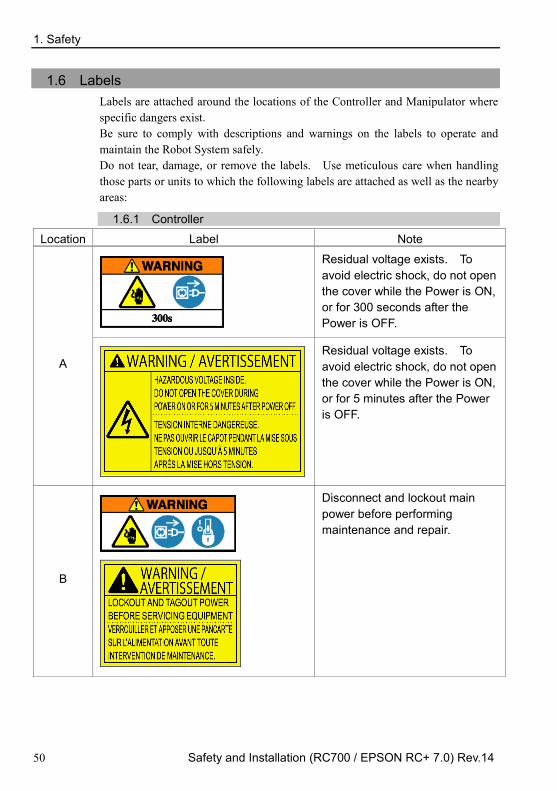
1. Safety
50 Safety and Installation (RC700 / EPSON RC+ 7.0) Rev.14
1.6 Labels Labels are attached around the locations of the Controller and Manipulator where specific dangers exist. Be sure to comply with descriptions and warnings on the labels to operate and maintain the Robot System safely. Do not tear, damage, or remove the labels. Use meticulous care when handling those parts or units to which the following labels are attached as well as the nearby areas:
1.6.1 Controller Location Label Note
A
Residual voltage exists. To avoid electric shock, do not open the cover while the Power is ON, or for 300 seconds after the Power is OFF.
Residual voltage exists. To avoid electric shock, do not open the cover while the Power is ON, or for 5 minutes after the Power is OFF.
B
Disconnect and lockout main power before performing maintenance and repair.

1. Safety
Safety and Installation (RC700 / EPSON RC+ 7.0) Rev.14 51
Location Label Note
C
Do not connect the followings to TP port. Connecting to the followings may result in malfunction of the device.
OPTIONAL DEVICE dummy plug,
OP500, OP500RC, JP500,
TP-3** series, and OP1
D
Hazardous voltage exists while the Manipulator is ON. To avoid electric shock, do not touch any internal electric parts.
RC700 / RC700-A Control Unit
C
D A
B
(Figure: RC700)
RC700DU / RC700DU-A Drive Unit
A D
B

1. Safety
52 Safety and Installation (RC700 / EPSON RC+ 7.0) Rev.14
1.6.2 Manipulator Location Label Note
A
Before loosening the base mounting screws, hold the arm and secure it tightly with a band to prevent hands or fingers from being caught in the Manipulator. For installation and transportation of robots, follow the directions in this manual.
To avoid the Manipulator from falling, support the Manipulator before removing the base mounting screws.
Follow the instructions in this manual for transportation and installation.

1. Safety
Safety and Installation (RC700 / EPSON RC+ 7.0) Rev.14 53
Location Label Note
B
Do not enter the operation area while the Manipulator is moving. The robot arm may collide against the operator. This is extremely hazardous and may result in serious safety problems.
C
Hazardous voltage exists while the Manipulator is ON. To avoid electric shock, do not touch any internal electric parts.
D
You may get your hand or fingers caught between the shaft and cover when bringing your hand close to moving parts. * Manipulators with bellows do not have this label for no danger of your hand or fingers being caught.
You may get your hand or fingers caught when bringing your hand close to moving parts.

1. Safety
54 Safety and Installation (RC700 / EPSON RC+ 7.0) Rev.14
Location Label Note
E
C4: Be careful of the arm falling due to its own weight when pressing the brake release switch. This label is attached on the optional brake release box. C8: When releasing the brakes, be careful of the arm falling due to its own weight. This label is attached on the Manipulator and optional brake release box.
When releasing the brakes, be careful of the arm falling due to its own weight. This warning label is attached on the Manipulator and optional brake release unit.
When the brake release box is used:
Details of procedures for releasing the brakes using the brake release box are described in the Manipulator manuals.

1. Safety
Safety and Installation (RC700 / EPSON RC+ 7.0) Rev.14 55
Location Label Note
When releasing the brakes, be careful of the arm falling / rotation due to its own weight.
F
Only authorized personnel should perform sling work and operate a crane and a forklift. When these operations are performed by unauthorized personnel, it is extremely hazardous and may result in serious bodily injury and/or severe equipment damage to the robot system.
G
HOT Be careful not to burn yourself.

1. Safety
56 Safety and Installation (RC700 / EPSON RC+ 7.0) Rev.14
Location of Labels
G1
B A
C
E
F
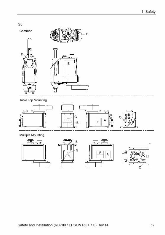
1. Safety
Safety and Installation (RC700 / EPSON RC+ 7.0) Rev.14 57
G3
C
D
B A
C
B
F
C
Common
Table Top Mounting
Multiple Mounting
G
G
E
F
A

1. Safety
58 Safety and Installation (RC700 / EPSON RC+ 7.0) Rev.14
G6
A
B D
C
C
Table Top Mounting G6-***S E
F
B
C C
D
Ceiling Mounting G6-***SR
E
A F
B D
C
Wall Mounting G6-***SW
E
A F
C

1. Safety
Safety and Installation (RC700 / EPSON RC+ 7.0) Rev.14 59
G10/G20
Table Top Mounting: G10/G20-**** Wall Mounting: G10/G20-****W
D
C
C A B
F
E
B
A
D
C E F
C
Ceiling Mounting: G10/G20-****R
B
A
C
C
D
E F

1. Safety
60 Safety and Installation (RC700 / EPSON RC+ 7.0) Rev.14
RS
C
D
C
C
A
C
E
B (Both sides)
Bottom
Side
Top
F

1. Safety
Safety and Installation (RC700 / EPSON RC+ 7.0) Rev.14 61
C4
Top View
Back View Lateral View
Front View
C
C
C
C
C
C
A
B
F
E
Lateral View
E: This label is attached on the UL-approved Manipulators and the optional brake release box

1. Safety
62 Safety and Installation (RC700 / EPSON RC+ 7.0) Rev.14
C8
Top View
Back View Lateral View Front View
C
C
C
C
C
C
A B
C
G
Cable Downward model
C
Lateral View
E
F D
C
G
Bottom View
(Illust: C8-A1401* (C8XL)) E: This label is attached on the UL-approved Manipulators and the optional brake release box

1. Safety
Safety and Installation (RC700 / EPSON RC+ 7.0) Rev.14 63
N2 S/N: N201000001~N201010000
A
E
D B
C
C
C
G G
G
Front View Lateral View Lateral View Back View
C
C
C
C
C
C
S/N: N201010001 or more
G
A
E
D B
C
C
G
G
C
C
C
C
C
G
E
Front View Lateral View Lateral View Back View
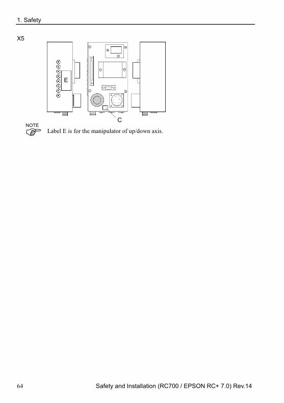
1. Safety
64 Safety and Installation (RC700 / EPSON RC+ 7.0) Rev.14
X5
E
C
Label E is for the manipulator of up/down axis.
NOTE

1. Safety
Safety and Installation (RC700 / EPSON RC+ 7.0) Rev.14 65
1.7 Safety Features The robot control system supports safety features described below. However, the user is recommended to strictly follow the proper usage of the robot system by thoroughly reading the attached manuals before using the system. Failure to read and understand the proper usage of the safety functions is highly dangerous.
Among the following safety features, the Emergency Stop Switch and Safety Door Input are particularly important. Make sure that these and other features function properly before operating the robot system.
For details, refer to the 2.5 Controller Installation - Safety Door Switch and Latch Release Switch.
Emergency Stop Switch
The EMERGENCY connector on the Controller has expansion Emergency Stop input terminals used for connecting the Emergency Stop switches. Pressing any Emergency Stop switch can shut off the motor power immediately and the robot system will enter the Emergency Stop condition. Stop category of Emergency Stop input: Category 0 (refer to Safety Standard IEC60204-1)
Safety Door Input
In order to activate this feature, make sure that the Safety Door Input switch is connected to the EMERGENCY connector at the Controller. When the safety door is opened, normally the Manipulator immediately stops the current operation, and the status of Manipulator power is operation-prohibited until the safety door is closed and the latched condition is released. In order to execute the Manipulator operation while the safety door is open, you must change the mode selector key switch on the Teach Pendant to the “Teach” mode. Manipulator operation is available only when the enable switch is on. In this case, the Manipulator is operated in low power status. Stop category of Safety door input: Category 1 (refer to Safety Standard IEC60204-1)
Low Power Mode The motor power is reduced in this mode. Executing a power status change instruction will change to the restricted (low power) status regardless of conditions of the safety door or operation mode. The restricted (low power) status ensures the safety of the operator and reduces the possibility of peripheral equipment destruction or damage caused by careless operation.
1. Safety
66 Safety and Installation (RC700 / EPSON RC+ 7.0) Rev.14
Dynamic Brake The dynamic brake circuit includes relays that short the motor armatures. The dynamic brake circuit is activated when there is an Emergency Stop input or when any of the following errors is detected: encoder cable disconnection, motor overload, irregular motor torque, motor speed error, servo error (positioning or speed overflow), irregular CPU, memory check-sum error and overheat condition inside the Motor Driver Module.
Motor Overload Detection
The dynamic brake circuit is activated when the system detects that the load on the motor has exceeded its capacity.
Irregular Motor Torque (out-of-control manipulator) Detection
The dynamic brake circuit is activated when irregularity with motor torque (motor output) is detected (in which case the Manipulator is out of control).
Motor Speed Error Detection The dynamic brake circuit is activated when the system detects that the motor is running at incorrect speed.
Positioning Overflow -Servo Error- Detection
The dynamic brake circuit is activated when the system detects that the difference between the Manipulator’s actual position and commanded position exceeds the margin of error allowed.
Speed Overflow -Servo Error- Detection
The dynamic brake circuit is activated when the Manipulator’s actual speed is detected to mark an overflow (the actual speed is outside the nominal range) error.
CPU Irregularity Detection
Irregularity of CPU that controls the motor is detected by the watchdog timer. The system CPU and the motor controlling CPU inside the Controller are also designed to constantly check each other for any discrepancies. If a discrepancy is detected, the dynamic brake circuit is activated.
Memory Check-sum Error Detection
The dynamic brake circuit is activated when a memory check-sum error is detected.
Overheat Detection at the Motor Driver Module
The dynamic brake circuit is activated when the temperature of the power device inside the Motor Driver module is above the nominal limit.
1. Safety
Safety and Installation (RC700 / EPSON RC+ 7.0) Rev.14 67
Relay Deposition Detection The dynamic brake circuit is activated when relay deposition is detected.
Over-Voltage Detection
The dynamic brake circuit is activated when the voltage of the Controller is above the normal limit.
AC Power Supply Voltage Drop Detection
The dynamic brake circuit is activated when the drop of the power supply voltage is detected.
Temperature Anomaly Detection
The temperature anomaly is detected. Fan Malfunction Detection
Malfunction of the fan rotation speed is detected.

1. Safety
68 Safety and Installation (RC700 / EPSON RC+ 7.0) Rev.14
1.8 Manipulator Specifications
G1
Item 4-axis spec
G1-171* G1-221* Mounting type Table Top
Arm length Arm #1, #2 175 mm 225 mm Arm #1 75 mm 125 mm Arm #2 100 mm
Weight (cables not included) 8 kg Driving method All joints AC servo motor
Max. operating speed *1
Joint #1, #2 2630 mm/s 3000 mm/s Joint #3 (Z) 1200 mm/s Joint #4 (U) 3000 deg/s
Repeatability Joint #1, #2 ± 0.005 mm ± 0.008 mm Joint #3 (Z) ± 0.01 mm Joint #4 (U) ± 0.01 deg
Max. motion range
Joint #1 ± 125 deg Joint #2 (Cleanroom model)
± 140 deg (± 140 deg)
± 152 deg (±149 deg)
Z stroke (Cleanroom model)
± 100 (80) mm
Joint #4 ± 360 deg
Max. pulse range (pulse)
Joint #1 − 1019449 ∼ 6262329 pulse Joint #2 (Cleanroom model)
± 2548623 (± 2548623)
± 2767076 (± 2712463)
Joint #3 (Cleanroom model)
− 1092267 to 0 (− 873813 to 0)
Joint #4 − 393216 to 393216
Resolution
Joint #1 3.43322E-05 deg/pulse Joint #2 5.49316E-05 deg/pulse Joint #3 9.15527E-05 mm/pulse Joint #4 9.15527E-04 deg/pulse
Motor power consumption All joints: 50 W
Payload Rated 0.5 kg Maximum 1 kg
Joint #4 allowable moment of inertia *2
Rated 0.0003 kg·m2 Maximum 0.004 kg·m2
Shaft diameter ø 8 mm Mounting hole 125 × 88 (4-M6)

1. Safety
Safety and Installation (RC700 / EPSON RC+ 7.0) Rev.14 69
Item 4-axis spec
G1-171* G1-221* Joint #3 down force 50 N Installed wire for customer use 24 pin (9+15)
Installed pneumatic tube for customer use
1 pneumatic tube (ø 4 mm) : 0.59 MPa (6 kgf/cm2 : 86 psi)
2 pneumatic tubes (ø 6 mm) : 0.59 MPa (6 kgf/cm2 : 86 psi)
Environmental requirements
Ambient temperature
5 to 40 deg C (with minimum temperature variation)
Ambient relative humidity
10 to 80 % RH (no condensation)
Vibration level 4.9 m/s2 (0.5G) or less Noise level *3 65dB Installation environment Cleanroom + ESD (ISO Class 3) *4
Assignable Value ( ) Default values
Speed 1 to (5) to 100 Accel *5 1 to (10) to 120 SpeedS 1 to (50) to 2000 AccelS 1 to (200) to 25000 Fine 0 to (10000) to 65000 Weight 0,100 to (0.5,100) to 1,100
Safety standard
CE Marking : EMC Directive Machinery Directive RoHS Directive
KC Marking / KCs Marking UL standards (In case of UL specification):
UL1740, ANSI/RIA R15.06, NFPA 79

1. Safety
70 Safety and Installation (RC700 / EPSON RC+ 7.0) Rev.14
Item 3-axis spec G1-171*Z G1-221*Z
Mounting type Table Top
Arm length Arm #1, #2 175 mm 225 mm Arm #1 75 mm 125 mm Arm #2 100 mm
Weight (cables not included) 8 kg Driving method All joints AC servo motor
Max. operating speed *1
Joint #1, #2 2630 mm/s 3000 mm/s Joint #3 (Z) 1200 mm/s Joint #4 (U) 3000 deg/s
Repeatability Joint #1, #2 ± 0.005 mm ± 0.008 mm Joint #3 (Z) ± 0.01 mm Joint #4 (U) -
Max. motion range
Joint #1 ± 125 deg Joint #2 (Cleanroom model)
± 135 deg. (± 123 deg.)
± 135 deg. (± 132 deg.)
Z stroke (Cleanroom model) ± 100 (80) mm
Joint #4 -
Max. pulse range (pulse)
Joint #1 − 1019449 to 6262329 pulse Joint #2 (Cleanroom model)
± 2457600 (± 2239147)
± 2457600 (± 2402987)
Joint #3 (Cleanroom model)
− 1092267 to 0 (− 873813 to 0)
Joint #4 − 393216 to 393216
Resolution
Joint #1 3.43322E-05 deg/pulse Joint #2 5.49316E-05 deg/pulse Joint #3 9.15527E-05 mm/pulse Joint #4 9.15527E-04 deg/pulse
Motor power consumption All joints: 50 W
Payload Rated 0.5 kg Maximum 1.5 kg
Joint #4 allowable moment of inertia *2
Rated - Maximum -
Shaft diameter ø 8 mm Mounting hole 125 × 88 (4-M6) Joint #3 down force 50 N Installed wire for customer use 24 pin (9 + 15)
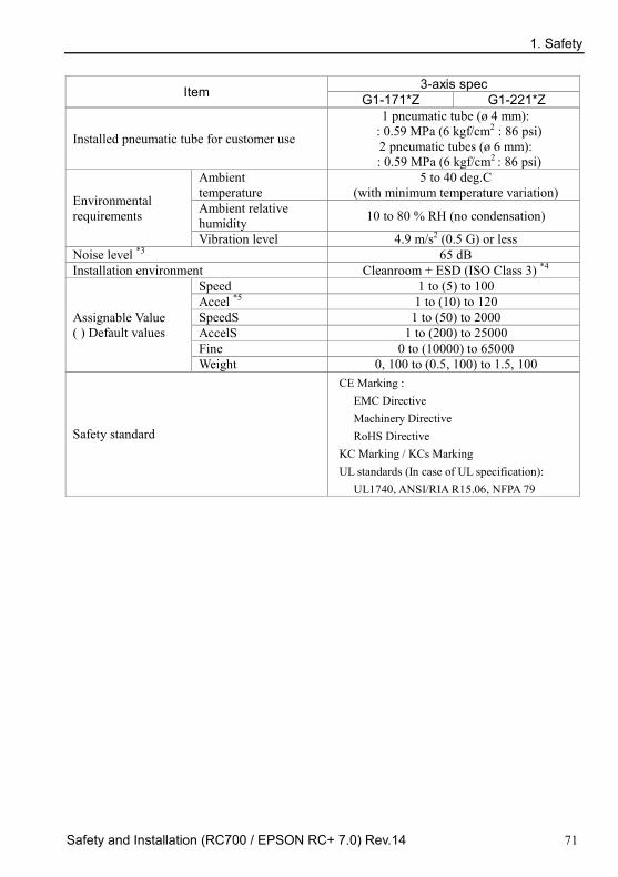
1. Safety
Safety and Installation (RC700 / EPSON RC+ 7.0) Rev.14 71
Item 3-axis spec G1-171*Z G1-221*Z
Installed pneumatic tube for customer use
1 pneumatic tube (ø 4 mm): : 0.59 MPa (6 kgf/cm2 : 86 psi)
2 pneumatic tubes (ø 6 mm): : 0.59 MPa (6 kgf/cm2 : 86 psi)
Environmental requirements
Ambient temperature
5 to 40 deg.C (with minimum temperature variation)
Ambient relative humidity 10 to 80 % RH (no condensation)
Vibration level 4.9 m/s2 (0.5 G) or less Noise level *3 65 dB Installation environment Cleanroom + ESD (ISO Class 3) *4
Assignable Value ( ) Default values
Speed 1 to (5) to 100 Accel *5 1 to (10) to 120 SpeedS 1 to (50) to 2000 AccelS 1 to (200) to 25000 Fine 0 to (10000) to 65000 Weight 0, 100 to (0.5, 100) to 1.5, 100
Safety standard
CE Marking : EMC Directive Machinery Directive RoHS Directive
KC Marking / KCs Marking UL standards (In case of UL specification):
UL1740, ANSI/RIA R15.06, NFPA 79
1. Safety
72 Safety and Installation (RC700 / EPSON RC+ 7.0) Rev.14
*1: In the case of PTP command. Maximum operating speed for CP command is 2000 mm/s on horizontal plane.
*2: In the case where the center of gravity is at the center of Joint #4. If the center of gravity is not at the center of Joint #4, set the parameter using Inertia command.
*3: Conditions of Manipulator during measurement as follows: Operating conditions : Under rated load, 4-joints simultaneous motion, maximum speed,
maximum acceleration, and duty 50%. Measurement point : Rear of the Manipulator, 1000 mm apart from the motion range, 50
mm above the base-installed surface.
*4: The exhaust system in the Cleanroom-model Manipulator draws air from the base interior and arm cover interior. A crack or other opening in the base unit can cause loss of negative air pressure in the outer part of the arm, which can cause increased dust emission. Seal firmly the exhaust port and the exhaust tube with vinyl tape. If the exhaust flow is not sufficient, dust particle emission may exceed the specified maximum level. Cleanliness level : Class ISO 3 (ISO14644-1)
Amount of Dust (0.1 µm diameter or larger) in 28317 cm3 (1cft) sample-air around the center of the motion rang: 10 particles or less.)
Exhaust System : Exhaust port : Inner diameter: ø8 mm Exhaust tube : Polyurethane tube
Outer diameter ø8 mm or Inner diameter ø16mm or larger Recommended exhaust flow rate: approx. 1000 cm3/s (Normal)
ESD specification uses resin materials with antistatic treatment. This model controls adhesion of dust due to electrification.
*5: In general use, Accel setting 100 is the optimum setting that maintains the balance of acceleration and vibration when positioning. Although values larger than 100 can be set to Accel, it is recommended to minimize the use of large values to necessary motions since operating the manipulator continuously with the large Accel setting may shorten the product life remarkably.

1. Safety
Safety and Installation (RC700 / EPSON RC+ 7.0) Rev.14 73
G3 Item G3 series Manipulator
Arm length Arm #1, #2 250 mm 300 mm 350 mm Arm #1 120 mm 170 mm 220 mm Arm #2 130 mm 130 mm 130 mm
Max. operating speed *1
Joint #1, #2 3550 mm/s 3950 mm/s 4350 mm/s Joints #3 1100 mm/s Joint #4 3000 deg/s
Repeatability Joint #1, #2 ± 0.008 mm ± 0.01 mm ± 0.01 mm Joint #3 ± 0.01 mm Joint #4 ± 0.005 deg
Payload Rated 1 kg Maximum 3 kg
Joints #4 allowable moment of inertia *2
Rated 0.005 kg·m2 Maximum 0.05 kg·m2
Resolution
Joint #1 0.0000343323 deg/pulse Joint #2 0.0000549316 deg/pulse Joint #3 0.0000878906 mm/pulse Joint #4 0.000240928 deg/pulse
Hand Shaft diameter ø 16 mm Through hole ø 11 mm
Mounting hole
Table top mounting 120 × 120 mm (4-M8)
Multiple mounting Wall mounting : 174 × 70 mm (4-M8)
Ceiling mounting : 120 × 120 mm (4-M8) / custom specification
Weight (cables not included) 14 kg : 31 lb Driving method All joints AC servo motor
Motor power consumption
Joint #1 200 W Joint #2 150 W Joint #3 150 W Joint #4 150 W
Option Mounting type - Multiple mounting Installation environment Cleanroom & ESD *3
Joint #3 down force 150 N Installed wire for customer use 15 (15 pin: D-sub) 15 cores
Installed pneumatic tube for customer use
2 pneumatic tubes (ø6 mm) : 0.59 MPa (6 kgf/cm2 : 86 psi) 1 pneumatic tubes (ø4 mm) : 0.59 MPa (6 kgf/cm2 : 86 psi)
Environmental requirements
Ambient temperature 5 to 40 deg C (with minimum temperature variation)
Ambient relative humidity 10 to 80% (no condensation) Noise level *4 LAeq = 70 dB (A)

1. Safety
74 Safety and Installation (RC700 / EPSON RC+ 7.0) Rev.14
Item G3 series Manipulator
Assignable Value ( ) Default values
Speed 1 to (5) to 100 Accel *5 1 to (10) to 120 SpeedS 1 to (50) to 2000 AccelS 1 to (200) to 25000 Fine 0 to (10000) to 65000 Weight 0, 130 to (1, 130) to 3, 130
Safety standard
CE Marking : EMC Directive Machinery Directive RoHS Directive
KC Marking / KCs Marking UL standards (In case of UL specification):
UL1740, ANSI/RIA R15.06, NFPA 79 Max. motion range (deg) (mm) / Max. pulse range (pulse)
Standard-model / Table Top Mounting Item G3-251S G3-301S-* G3-351S-*
Max. motion range (deg), (mm)
Straight Joint #1 ± 140 Joint #2 ± 141 ± 142
Curved Joint #1
Right hand - − 125 to 150 − 110 to 165 Left hand - − 150 to 125 − 165 to 110
Joint #2 Right hand - − 135 to 150 − 120 to 165 Left hand - − 150 to 135 − 165 to 120
Common Joint #3 150 mm Joint #4 ± 360
Max. pulse range (pulse)
Straight Joint #1 − 1456356 to 6699236 Joint #2 ± 2566827 ± 2585032
Curved
Joint #1 Right hand - − 1019449
to 6990507 − 582543
to 7427414
Left hand - − 1747627 to 6262329
− 2184534 to 5825423
Joint #2 Right hand - − 2457600
to 2730667 − 2184534 to 3003734
Left hand - − 2730667 to 2457600
− 3003734 to 2184534
Common Joint #3 −1706667 to 0 Joint #4 ± 1494221

1. Safety
Safety and Installation (RC700 / EPSON RC+ 7.0) Rev.14 75
Standard-model / Multiple Mounting Item G3-301SM G3-351SM-*
Max. motion range (deg), (mm)
Straight Joint #1 ± 115 ± 120 Joint #2 ± 135 ± 142
Curved Joint #1 Right hand - − 105 to 130
Left hand - − 130 to 105
Joint #2 Right hand - − 120 to 160 Left hand - − 160 to 120
Common Joint #3 150 mm Joint #4 ± 360
Max. pulse range (pulse)
Straight Joint #1 − 728178 to 5971058 − 873814 to 6116694
Joint #2 ± 2457600 ± 2585032
Curved Joint #1
Right hand - − 436907 to 6407965 Left hand - − 1165085 to 5679787
Joint #2 Right hand - − 2184534 to 2912712 Left hand - − 2912712 to 2184534
Common Joint #3 −1706667 to 0 Joint #4 ± 1494221
Cleanroom & ESD model / Table Top Mounting Item G3-251C G3-301C-* G3-351C-*
Max. motion range (deg), (mm)
Straight Joint #1 ± 140 Joint #2 ± 137 ± 141 ± 142
Curved Joint #1
Right hand - − 125 to 150 − 110 to 165 Left hand - − 150 to 125 − 165 to 110
Joint #2 Right hand - − 135 to 145 − 120 to 160 Left hand - − 145 to 135 − 160 to 120
Common Joint #3 120 mm Joint #4 ± 360
Max. pulse range (pulse)
Straight Joint #1 − 1456356 to 6699236 Joint #2 ± 2494009 ± 2566827 ± 2585032
Curved
Joint #1 Right hand - − 1019449
to 6990507 − 582543
to 7427414
Left hand - − 1747627 to 6262329
− 2184534 to 5825423
Joint #2 Right hand - − 2457600
to 2639645 − 2184534 to 2912712
Left hand - − 2639645 to 2457600
− 2912712 to 2184534
Common Joint #3 − 1365334 to 0 Joint #4 ± 1494221

1. Safety
76 Safety and Installation (RC700 / EPSON RC+ 7.0) Rev.14
Cleanroom & ESD model / Multiple Mounting Item G3-301CM G3-351CM-*
Max. motion range (deg), (mm)
Straight Joint #1 ± 115 ± 120 Joint #2 ± 135 ± 142
Curved Joint #1
Right hand - − 105 to 130 Left hand - − 130 to 105
Joint #2 Right hand - − 120 to 150 Left hand - − 150 to 120
Common Joint #3 120 mm Joint #4 ± 360
Max. pulse range (pulse)
Straight Joint #1 − 728178
to 5971058 − 873814
to 6116694 Joint #2 ± 2457600 ± 2585032
Curved
Joint #1 Right hand - − 436907
to 6407965
Left hand - − 1165085 to 5679787
Joint #2 Right hand - − 2184534
to 2730667
Left hand - − 2730667 to 2187534
Common Joint #3 − 1365334 to 0 Joint #4 ± 1494221

1. Safety
Safety and Installation (RC700 / EPSON RC+ 7.0) Rev.14 77
*1: In the case of PTP command. Maximum operating speed for CP command is 2000 mm/s on horizontal plane.
*2: In the case where the center of gravity is at the center of Joint #4. If the center of gravity is not at the center of Joint #4, set the parameter using Inertia command.
*3: The exhaust system in the Cleanroom-model Manipulator draws air from the base interior and arm cover interior. A crack or other opening in the base unit can cause loss of negative air pressure in the outer part of the arm, which can cause increased dust emission. Do not remove the maintenance cover on the front of the base. Seal the exhaust port and the exhaust tube with vinyl tape so that the joint is airtight. If the exhaust flow is not sufficient, dust particle emission may exceed the specified maximum level. Cleanliness level : Class ISO 3 (ISO14644-1)
Amount of dust (0.1 µm diameter or larger) in 28317 cm3 (1cft) sample-air around the center of the motion rang: 10 particles or less.
Exhaust System : Exhaust port diameter: Inner diameter: ø12 mm / Outer diameter: ø16 mm Exhaust tube: Polyurethane tube Outer diameter: ø12 mm (Inner diameter:ø8 mm) or Inner diameter ø16mm or larger Recommended exhaust flow rate : approx. 1000 cm3/s (Normal)
ESD specification uses resin materials with antistatic treatment. This model controls adhesion of dust due to electrification.
*4: Conditions of Manipulator during measurement as follows: Operating conditions : Under rated load, 4-joints simultaneous motion, maximum speed,
maximum acceleration, and duty 50%. Measurement point : Rear of the Manipulator, 1000 mm apart from the motion range, 50
mm above the base-installed surface.
*5: In general use, Accel setting 100 is the optimum setting that maintains the balance of acceleration and vibration when positioning. Although values larger than 100 can be set to Accel, it is recommended to minimize the use of large values to necessary motions since operating the manipulator continuously with the large Accel setting may shorten the product life remarkably.
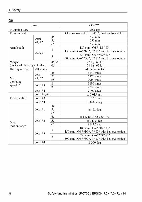
1. Safety
78 Safety and Installation (RC700 / EPSON RC+ 7.0) Rev.14
G6 Item G6-****
Mounting type Table Top Environment Cleanroom-model + ESD *1, Protected-model *2
Arm length
Arm #1, #2
45 450 mm 55 550 mm 65 650 mm
Arm #3 1 180 mm : G6-**1S*, D*
150 mm : G6-**1C*, P*, D* with bellows option
3 330 mm : G6-**3S*, D* 300 mm : G6-**3C*, P*, D* with bellows option
Weight (not include the weight of cables)
45/55 27 kg : 60 lb 65 28 kg : 62 lb
Driving method All joints AC servo motor
Max. operating speed *3
Joint #1, #2
45 6440 mm/s 55 7170 mm/s 65 7900 mm/s
Joint #3 1 1100 mm/s 3 2350 mm/s
Joint #4 2400 deg/s
Repeatability Joint #1, #2 ± 0.015 mm Joint #3 ± 0.01 mm Joint #4 ± 0.005 deg
Max. motion range
Joint #1 45
± 152 deg 55 65
Joint #2 45 ± 142 to 147.5 deg *a 55 ± 147.5 deg 65 ±147.5 deg
Joint #3 1 180 mm : G6-**1S*, D*
150 mm : G6-**1C*, P*, D* with bellows option
3 330 mm : G6-**3S*, D* 300 mm : G6-**3C*, P*, D* with bellows option
Joint #4 ± 360 deg
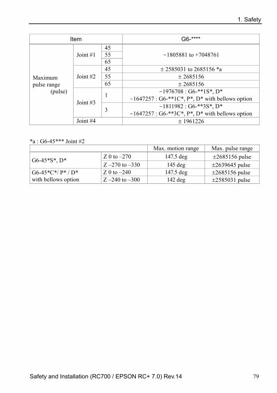
1. Safety
Safety and Installation (RC700 / EPSON RC+ 7.0) Rev.14 79
Item G6-****
Maximum pulse range
(pulse)
Joint #1 45
-1805881 to +7048761 55 65
Joint #2 45 ± 2585031 to 2685156 *a 55 ± 2685156 65 ± 2685156
Joint #3 1 -1976708 : G6-**1S*, D*
-1647257 : G6-**1C*, P*, D* with bellows option
3 -1811982 : G6-**3S*, D* -1647257 : G6-**3C*, P*, D* with bellows option
Joint #4 ± 1961226
*a : G6-45*** Joint #2 Max. motion range Max. pulse range
G6-45*S*, D* Z 0 to –270 147.5 deg ±2685156 pulse Z –270 to –330 145 deg ±2639645 pulse
G6-45*C*/ P* / D* with bellows option
Z 0 to –240 147.5 deg ±2685156 pulse Z –240 to –300 142 deg ±2585031 pulse

1. Safety
80 Safety and Installation (RC700 / EPSON RC+ 7.0) Rev.14
Item G6-****R G6-****W Mounting type Ceiling Wall Environment Cleanroom-model + ESD *1, Protected-model *2
Arm length
Arm #1, #2
45 450 mm 55 550 mm 65 650 mm
Arm #3 1 180 mm : G6-**1S*, D*
150 mm : G6-**1C*, P*, D* with bellows option
3 330 mm : G6-**3S*, D* 300 mm : G6-**3C*, P*, D* with bellows option
Weight (not include the weight of cables)
45/55 27 kg : 60 lb 29 kg : 64 lb 65 28 kg : 62 lb 29.5 kg : 65 lb
Driving method All joints AC servo motor
Max. operating speed *3
Joint #1, #2
45 6440 mm/s 55 7170 mm/s 65 7900 mm/s
Joint #3 1 1100 mm/s 3 2350 mm/s
Joint #4 2400 deg/s
Repeatability Joint #1, #2 ± 0.015 mm Joint #3 ± 0.01 mm Joint #4 ± 0.005 deg
Max. motion range
Joint #1 45 ± 120 deg ± 105 deg 55
± 152 deg ± 135 deg 65 ± 148 deg
Joint #2
45 ± 130 deg
55 ± 147.5 deg : S ± 145 deg : C*, P*, D* with bellows option
65 ± 147.5 deg
Joint #3 1 180 mm : G6-**1S*, D*
150 mm : G6-**1C*, P*, D* with bellows option
3 330 mm : G6-**3S*, D* 300 mm : G6-**3C*, P*, D* with bellows option
Joint #4 ± 360 deg

1. Safety
Safety and Installation (RC700 / EPSON RC+ 7.0) Rev.14 81
Item G6-****R G6-****W Mounting type Ceiling Wall
Maximum pulse range
(pulse)
Joint #1 45 -873814 to +6116694 -436907 to +5679787 55
-1805881 to +7048761 -1310720 to +6553600 65 -1689373 to +6932253
Joint #2
45 ± 2366578
55 ± 2685156 : S ± 2639645 : C*, P*, D* with bellows option
65 ± 2685156
Joint #3 1 -1976708 : G6-**1S*, D*
-1647257 : G6-**1C*, P*, D* with bellows option
3 -1811982 : G6-**3S*, D* -1647257 : G6-**3C*, P*, D* with bellows option
Joint #4 ± 1961226

1. Safety
82 Safety and Installation (RC700 / EPSON RC+ 7.0) Rev.14
Item G6-*****
Resolution
Joint #1 0.0000343 deg/pulse Joint #2 0.0000549 deg/pulse
Joint #3 1 0.0000911 mm/pulse 3 0.0001821 mm/pulse
Joint #4 0.0001836 deg/pulse
Motor power consumption
Joint #1 400 W Joint #2 400 W Joint #3 200 W Joint #4 100 W
Payload Rated 3 kg Maximum 6 kg
Joint #4 allowable moment of inertia *4
Rated 0.01 kg·m2 Maximum 0.12 kg·m2
Hand Shaft diameter ø20 mm Through hole ø14 mm
Joint #3 down force 150 N Installed wire for customer use 24 (15 pin + 9 pin : D-sub)
Installed pneumatic tube for customer use
2 pneumatic tubes (ø6 mm) : 0.59 MPa (6 kgf/cm2 : 86 psi)
2 pneumatic tubes (ø4 mm) : 0.59 MPa (6 kgf/cm2 : 86 psi)
Environmental requirements
Ambient temperature
5 to 40deg C (with minimum temperature variation)
Ambient relative humidity 10 to 80% (no condensation)
Noise level *5 LAeq = 70 dB(A)
Assignable Value ( ) Default values
Speed 1 to (5) to 100 Accel *6 1 to (10) to 120 SpeedS 1 to (50) to 2000 AccelS 1 to (200) to 25000 Fine 0 to (10000) to 65000 Weight 0, 250 to (3, 250) to 6, 250
Safety standard
CE Marking : EMC Directive Machinery Directive RoHS Directive
KC Marking / KCs Marking UL standards (In case of UL specification):
UL1740, ANSI/RIA R15.06, NFPA 79

1. Safety
Safety and Installation (RC700 / EPSON RC+ 7.0) Rev.14 83
*1: The exhaust system in the Cleanroom-model Manipulator (G6-***C*) draws air from the base interior and arm cover interior. A crack or other opening in the base unit can cause loss of negative air pressure in the outer part of the arm, which can cause increased dust emission. Do not remove the maintenance cover on the front of the base. Seal the exhaust port and the exhaust tube with vinyl tape so that the joint is airtight. If the exhaust flow is not sufficient, dust particle emission may exceed the specified maximum level.
Cleanliness level : Class ISO 3 (ISO14644-1)
Amount of Dust (0.1 µm diameter or larger) in 28317 cm3 (1cft) sample-air around the center of the motion rang: 10 particles or less.)
Exhaust System : Exhaust port diameter: Inner diameter: ø12 mm/Outer diameter: ø16 mm Exhaust tube : Polyurethane tube Outer diameter: ø12 mm (Inner diameter: ø8 mm) or Inner diameter ø16 mm or larger Recommended exhaust flow rate: Approx. 1000 cm3/s (Normal)
ESD specification uses resin materials with antistatic treatment. This model controls adhesion of dust due to electrification.
*2: IP (International Protection) for the Protected-model Manipulator indicates International Standard of the protection level against dust and water.
Normal G6-***D* Manipulators do not have bellows. The normal G6-***D* Manipulator (without bellows option) operates under adverse conditions with oily mist.
If necessary, select the bellows option at shipment.
The Manipulators with bellows (option) comply with grade of protection IP54 (IEC 60529, JIS C0920).
Model Degree of protection
G6-***D* with bellows option
IP54 Dust: 5 Dust shall not ingress in a quantity to interfere
with satisfactory operation of the equipment.
Water: 4 Water splashing against the enclosure from any direction shall have no harmful effect.
G6-***P* IP65 Dust: 6 No ingress of dust.
Water: 5 Water projected by a nozzle against enclosure from any direction shall have no harmful effects.
*3: In the case of PTP command. Maximum operating speed for CP command is 2000 mm/s on horizontal plane.
*4: In the case where the center of gravity is at the center of Joint #4. If the center of gravity is not at the center of Joint #4, set the parameter using Inertia command.
1. Safety
84 Safety and Installation (RC700 / EPSON RC+ 7.0) Rev.14
*5: Conditions of Manipulator during measurement as follows: Operating conditions : Under rated load, 4-joints simultaneous motion, maximum
speed, maximum acceleration, and duty 50%. Measurement point : Rear of the Manipulator, 1000 mm apart from the motion range,
50 mm above the base-installed surface.
*6: In general use, Accel setting 100 is the optimum setting that maintains the balance of acceleration and vibration when positioning. Although values larger than 100 can be set to Accel, it is recommended to minimize the use of large values to necessary motions since operating the manipulator continuously with the large Accel setting may shorten the product life remarkably.

1. Safety
Safety and Installation (RC700 / EPSON RC+ 7.0) Rev.14 85
G10/G20
Item G10/G20-**** Mounting type Table Top
Environment Cleanroom-model + ESD *1 , Protected-model *2
Arm length
Arm #1, #2 65 650 mm (G10 only) 85 850 mm (G10, G20) A0 1000 mm (G20 only)
Arm #3
1 180 mm : G10/G20-**1S*, D* 150 mm : G10/G20-**1C*, P*,
D* with bellows option
4 420 mm : G10/G20-**4S*, D* 390 mm : G10/G20-**4C*, P*,
D* with bellows option Weight (not include the weight of cables)
G10 65 46 kg: 102 lb G10/G20 85 48 kg: 106 lb G20 A0 50 kg: 111 lb
Driving method All joints AC servo motor
Max. operating speed *3
Joint #1, #2 65 8800 mm/s 85 11000 mm/s A0 11500 mm/s
Joint #3 1 1100 mm/s 4 2350 mm/s
Joint #4 G10 2400 deg/s G20 1700 deg/s
Repeatability Joint #1, #2 ± 0.025 mm Joint #3 ± 0.01 mm Joint #4 ± 0.005 deg
Max. motion range
Joint #1 65
± 152 deg 85 A0
Joint #2 65
± 152.5 deg *a 85 A0
Joint #3
1 180 mm : G10/G20-**1S*, D* 150 mm : G10/G20-**1C*, P*,
D* with bellows option
4 420 mm : G10/G20-**4S*, D* 390 mm : G10/G20-**4C*, P*,
D* with bellows option Joint #4 ± 360 deg

1. Safety
86 Safety and Installation (RC700 / EPSON RC+ 7.0) Rev.14
Item G10/G20-****
Max. pulse range (pulse)
Joint #1 65
−1805881 to +7048761 85 A0
Joint #2 65
± 2776178 *a 85 A0
Joint #3
1 −1946420 : G10/G20-**1S*, D* −1622016 : G10/G20-**1C*, P*,
D* with bellows option
4 −2270823 : G10/G20-**4S*, D* −2108621 : G10/G20-**4C*, P*,
D* with bellows option
Joint #4 G10 ± 1951517 G20 ± 2752512
NOTE The length of Arm #1 + #2 varies in different Manipulator models. 65 : 650 mm G10 only 85 : 850 mm G10 / G20 A0 : 1000 mm G20 only

1. Safety
Safety and Installation (RC700 / EPSON RC+ 7.0) Rev.14 87
Item G10/G20-****R G10/G20-*****W Mounting type Ceiling Wall
Environment Cleanroom-model + ESD *1
Protected-model *2
Arm length
Arm #1, #2 65 650 mm (G10 only) 85 850 mm (G10, G20) A0 1000 mm (G20 only)
Arm #3
1 180 mm : G10/G20-**1S*, D* 150 mm : G10/G20-**1C*, P*,
D* with bellows option
4 420 mm : G10/G20-**4S*, D* 390 mm : G10/G20-**4C*, P*,
D* with bellows option Weight (not include the weight of cables)
G10 65 46 kg: 102 lb 51 kg: 113 lb G10/G20 85 48 kg: 106 lb 53 kg: 117 lb G20 A0 50 kg: 111 lb 55 kg: 122 lb
Driving method All joints AC servo motor
Max. operating speed *3
Joints #1, #2 65 8800 mm/s 85 11000 mm/s A0 11500mm/s
Joint #3 1 1100 mm/s 4 2350 mm/s
Joint #4 G10 2400 deg/s G20 1700 deg/s
Repeatability Joint #1, #2 ± 0.025 mm Joint #3 ± 0.01 mm Joint #4 ± 0.005 deg
Max. motion range
Joint #1 65 ± 107 deg
± 107 deg 85 ± 152 deg A0
Joint #2 65 ± 130 deg 85
± 152.5 deg *a A0
Joint #3
1 180 mm : G10/G20-**1S*, D* 150 mm : G10/G20-**1C*, P*,
D* with bellows option
4 420 mm : G10/G20-**4S*, D* 390 mm : G10/G20-**4C*, P*,
D* with bellows option Joint #4 ± 360 deg

1. Safety
88 Safety and Installation (RC700 / EPSON RC+ 7.0) Rev.14
Item G10/G20-****R G10/G20-*****W
Max. pulse range
(pulse)
Joint #1 65 −495161
to +5738041 −495161 to +5738041 85 −1805881
to +7048761 A0
Joint #2 65 ± 2366578 85
± 2776178 *a A0
Joint #3
1 −1946420 : G10/G20-**1S*, D* −1622016 : G10/G20-**1C*, P*,
D* with bellows option
4 −2270823 : G10/G20-**4S*, D* −2108621 : G10/G20-**4C*, P*,
D* with bellows option
Joint #4 G10 ± 1951517 G20 ± 2752512
*a : The Joint #2 values for the following manipulators
Max. motion range Max. pulse range G10/G20-85C, P, D with bellows option (Z: −360 to −390 only) G10/G20-85CW, PW, DW with bellows option G10/G20-85CR, PR, DR with bellows option
± 151 deg ± 2748871

1. Safety
Safety and Installation (RC700 / EPSON RC+ 7.0) Rev.14 89
Item G10-***** G20-*****
Resolution
Joint #1 0.0000343 deg/pulse Joint #2 0.0000549 deg/pulse
Joint #3 1 0.0000925 mm/pulse 4 0.000185 mm/pulse
Joint #4 0.0001845 deg/pulse 0.0001308 deg/pulse
Motor power consumption
Joint #1 750 W Joint #2 600 W Joint #3 400 W Joint #4 150 W
Payload Rated 5 kg 10 kg Maximum 10 kg 20 kg
Joint #4 allowable moment of inertia *4
Rated 0.02 kg·m2 0.05 kg·m2 Maximum 0.25 kg·m2 0.45 kg·m2
Hand Shaft diameter ø25 mm Through hole ø18 mm
Joint #3 down force 250 N Installed wire for customer use 24 (15 pin + 9 pin : D-sub)
Installed pneumatic tube for customer use
2 pneumatic tubes (ø6 mm) : 0.59 MPa (6 kgf/cm2 : 86 psi)
2 pneumatic tubes (ø4 mm) : 0.59 MPa (6 kgf/cm2 : 86 psi)
Environmental requirements
Ambient temperature
5 to 40 degC (with minimum temperature variation)
Ambient relative humidity 10 to 80% (no condensation)
Noise level *5 LAeq = 70 dB(A)
Assignable Value ( ) Default values
Speed 1 to (5) to 100 Accel *6 1 to (10) to 120 SpeedS 1 to (50) to 2000 AccelS 1 to (200) to 25000 Fine 0 to (10000) to 65000 Weight 0, 400 to (10, 400) to 20, 400
Safety standard
CE Marking : EMC Directive Machinery Directive RoHS Directive
KC Marking / KCs Marking UL standards (In case of UL specification):
UL1740, ANSI/RIA R15.06, NFPA 79

1. Safety
90 Safety and Installation (RC700 / EPSON RC+ 7.0) Rev.14
*1: The exhaust system in the Cleanroom-model Manipulator (G10/G20-***C*) draws air from the base interior and arm cover interior. A crack or other opening in the base unit can cause loss of negative air pressure in the outer part of the arm, which can cause increased dust emission. Do not remove the maintenance cover on the front of the base. Seal the exhaust port and the exhaust tube with vinyl tape so that the joint is airtight. If the exhaust flow is not sufficient, dust particle emission may exceed the specified maximum level. Cleanliness level: Class ISO 3 (ISO14644-1)
Amount of dust (0.1 µm diameter or larger) in 28317 cm3 (1cft) sample-air around the center of the motion rang: 10 particles or less.)
Exhaust System: Exhaust port diameter: Inner diameter: ø12 mm/Outer diameter: ø16 mm Exhaust tube : Polyurethane tube Outer diameter: ø12 mm (Inner diameter: ø8 mm) or Inner diameter ø16mm or larger Recommended exhaust flow rate: Approx. 1000 cm3/s
(Normal)
ESD specification uses resin materials with antistatic treatment. This model controls
adhesion of dust due to electrification.
*2: IP (International Protection) for the Protected-model Manipulator indicates International Standard of the protection level against dust and water.
Normal G10/G20-***D* Manipulators do not have bellows. The normal G10/G20-***D* Manipulator (without bellows option) operates under adverse conditions with oily mist.
If necessary, select the bellows option at shipment.
The Manipulators with bellows (option) comply with grade of protection IP54 (IEC 60529, JIS C0920).
Model Degree of protection
G10/G20-***D* with bellows option IP54
Dust: 5 Dust shall not ingress in a quantity to interfere with satisfactory operation of the equipment.
Water: 4 Water splashing against the enclosure from any direction shall have no harmful effect.
G10/G20-***P* IP65
Dust: 6 No ingress of dust.
Water: 5 Water projected by a nozzle against enclosure from any direction shall have no harmful effects.
*3: In the case of PTP command. Maximum operating speed for CP command is 2000 mm/s on horizontal plane.
1. Safety
Safety and Installation (RC700 / EPSON RC+ 7.0) Rev.14 91
*4: In the case where the center of gravity is at the center of Joint #4. If the center of gravity is not at the center of Joint #4, set the parameter using Inertia command.
*5: Conditions of Manipulator during measurement as follows: Operating conditions : Under rated load, 4-joint simultaneous motion, maximum speed,
maximum acceleration, and duty 50%. Measurement point : Rear of the Manipulator, 1000 mm apart from the motion range, 50
mm above the base-installed surface.
*6: In general use, Accel setting 100 is the optimum setting that maintains the balance of acceleration and vibration when positioning. Although values larger than 100 can be set to Accel, it is recommended to minimize the use of large values to necessary motions since operating the manipulator continuously with the large Accel setting may shorten the product life remarkably.

1. Safety
92 Safety and Installation (RC700 / EPSON RC+ 7.0) Rev.14
RS3
Item RS3-351*
Arm length Arm #1, #2 350 mm Arm #1 175 mm Arm #2 175 mm
Max. operating speed *1 Joint #1, #2 6237 mm/s Joint #3 1100 mm/s Joint #4 2600 deg/s
Repeatability Joint #1, #2 ± 0.01 mm Joint #3 ± 0.01 mm Joint #4 ± 0.01 deg
Payload Rated 1 kg Maximum 3 kg
Joint #4 allowable moment of inertia *2
Rated 0.005 kg·m2 Maximum 0.05 kg·m2
Max. motion range
Joint #1 ± 225 deg Joint #2 ± 225 deg
Joint #3 RS*-**1S 130 mm RS*-**1C 100 mm
Joint #4 ± 720 deg
Max. pulse range (pulse)
Joint #1 − 2560000 to + 5973334 pulse Joint #2 ± 4177920 pulse
Joint #3 RS*-**1S − 1479112 pulse to 0 pulse RS*-**1C − 1137778 pulse to 0 pulse
Joint #4 ± 3145728 pulse
Resolution
Joint #1 0.0000527 deg/pulse Joint #2 0.0000538 deg/pulse Joint #3 0.0000879 mm/pulse Joint #4 0.000229 deg/pulse
Hand Shaft diameter ø 16 mm Through hole ø 11 mm
Mounting hole 6-M6 Weight (cables not included) 17 kg: 38 lb Driving method All joints AC servo motor
Motor power consumption
Joint #1 400 W Joint #2 200 W Joint #3 150 W Joint #4 100 W
Option Installation environment Cleanroom & ESD *3 Joint #3 down force 150 N Installed wire for customer use 15 wires: D-sub / 15 pin connectors

1. Safety
Safety and Installation (RC700 / EPSON RC+ 7.0) Rev.14 93
Item RS3-351*
Installed pneumatic tube for customer use
2 pneumatic tubes (ø 6 mm) : 0.59 MPa (6 kgf/cm2 : 86 psi)
1 pneumatic tube (ø 4 mm) : 0.59 MPa (6 kgf/cm2 : 86 psi)
Environmental requirements
Ambient temperature
5 to 40 degC (with minimum temperature variation)
Ambient relative humidity 10 to 80% RH (no condensation)
Noise level *4 LAeq = 65 dB(A) or under
Assignable Value ( ) Default values
Speed 1 to (5) to 100 Accel *5 1 to (10) to 120 SpeedS 1 to (50) to 2000 AccelS 1 to (200) to 25000 Fine 0 to (10000) to 65000 Weight 0, 175 to (1, 175) to 3, 175
Safety standard
CE Marking : EMC Directive Machinery Directive RoHS Directive
KC Marking / KCs Marking UL standards (In case of UL specification):
UL1740, ANSI/RIA R15.06, NFPA 79

1. Safety
94 Safety and Installation (RC700 / EPSON RC+ 7.0) Rev.14
*1: In the case of PTP command. Maximum operating speed for CP command is 2000 mm/s on horizontal plane.
*2: In the case where the center of gravity is at the center of Joint #4. If the center of gravity is not at the center of Joint #4, set the parameter using Inertia command.
*3: The exhaust system in the Cleanroom-model Manipulator draws air from the base interior and arm cover interior. A crack or other opening in the base unit can cause loss of negative air pressure in the outer part of the arm, which can cause increased dust emission. Do not remove the maintenance cover on the front of the base. Seal the exhaust port and the exhaust tube with vinyl tape so that the joint is airtight. If the exhaust flow is not sufficient, dust particle emission may exceed the specified maximum level. Cleanliness level: Class ISO 3 (ISO14644-1)
Amount of Dust (0.1 µm diameter or larger) in 28317 cm3 (1cft) sample-air around the center of the motion rang: 10 particles or less.)
Exhaust System: Exhaust port diameter: Inner diameter: ø12 mm / Outer diameter: ø16 mm Exhaust tube : Polyurethane tube Outer diameter: ø12 mm (Inner diameter: ø8 mm) or Inner diameter ø16mm or larger Recommended exhaust flow rate: approx. 1000 cm3/s (Normal)
ESD specification uses resin materials with antistatic treatment. This model controls adhesion of dust due to electrification.
*4: Conditions of Manipulator during measurement as follows: Operating conditions : Under rated load, 4-joints simultaneous motion, maximum
speed, maximum acceleration, and duty 50%. Measurement point : Rear of the Manipulator, 1000 mm apart from the motion
range, 50 mm above the base-installed surface.
*5: In general use, Accel setting 100 is the optimum setting that maintains the balance of acceleration and vibration when positioning. Although values larger than 100 can be set to Accel, it is recommended to minimize the use of large values to necessary motions since operating the manipulator continuously with the large Accel setting may shorten the product life remarkably.

1. Safety
Safety and Installation (RC700 / EPSON RC+ 7.0) Rev.14 95
RS4
Item RS4-551*
Arm length Arm #1, #2 550 mm Arm #1 275 mm Arm #2 275 mm
Max. operating speed *1
Joint #1, #2 7400 mm/s Joint #3 1100 mm/s Joint #4 2600 deg/s
Repeatability Joint #1, #2 ± 0.015 mm Joint #3 ± 0.01 mm Joint #4 ± 0.01 deg
Payload Rated 1 kg Maximum 4 kg
Joint #4 allowable moment of inertia *2
Rated 0.005 kg·m2 Maximum 0.05 kg·m2
Max. motion range
Joint #1 ± 225 deg Joint #2 ± 225 deg
Joint #3 RS*-**1S 130 mm RS*-**1C 100 mm
Joint #4 ± 720 deg
Max. pulse range (pulse)
Joint #1 − 4096000 to + 9557334 pulse Joint #2 ± 4177920 pulse
Joint #3 RS*-**1S − 1479112 pulse to 0 pulse RS*-**1C − 1137778 pulse to 0 pulse
Joint #4 ± 3145728 pulse
Resolution
Joint #1 0.0000330 deg/pulse Joint #2 0.0000538 deg/pulse Joint #3 0.0000879 mm/pulse Joint #4 0.000229 deg/pulse
Hand diameter Shaft diameter ø 16 mm Through hole ø 11 mm
Mounting hole 6-M6 Weight (cables not included) 19 kg: 42 lb Driving method All joints AC servo motor
Motor power consumption
Joint #1 400 W Joint #2 400 W Joint #3 150 W Joint #4 100 W
Option Environment Cleanroom & ESD *3 Joint #3 down force 150 N Installed wire for customer use 15 wires: D-sub / 15 pin connectors

1. Safety
96 Safety and Installation (RC700 / EPSON RC+ 7.0) Rev.14
Item RS4-551*
Installed pneumatic tube for customer use
2 pneumatic tubes (ø 6 mm) : 0.59 MPa (6 kgf/cm2 : 86 psi)
1 pneumatic tube (ø 4 mm) : 0.59 MPa (6 kgf/cm2 : 86 psi)
Environmental requirements
Ambient temperature
5 to 40 degC (with minimum temperature variation)
Ambient relative humidity 10 to 80% RH (no condensation)
Noise level *4 LAeq = 65 dB(A) or less
Assignable Value ( ) Default values
Speed 1 to (5) to 100 Accel *5 1 to (10) to 120 SpeedS 1 to (50) to 2000 AccelS 1 to (200) to 25000 Fine 0 to (10000) to 65000 Weight 0, 275 to (1, 275) to 4, 275
Safety standard
CE Marking : EMC Directive Machinery Directive RoHS Directive
KC Marking / KCs Marking UL standards (In case of UL specification):
UL1740, ANSI/RIA R15.06, NFPA 79

1. Safety
Safety and Installation (RC700 / EPSON RC+ 7.0) Rev.14 97
*1: In the case of PTP command. Maximum operating speed for CP command is 2000 mm/s on horizontal plane.
*2: In the case where the center of gravity is at the center of Joint #4. If the center of gravity is not at the center of Joint #4, set the parameter using Inertia command.
*3: The exhaust system in the Cleanroom-model Manipulator draws air from the base interior and arm cover interior together. A crack or other opening in the base unit can cause loss of negative air pressure in the outer part of the arm, which can cause increased dust emission. Do not remove the maintenance cover on the front of the base. Seal the exhaust port and the exhaust tube with vinyl tape so that the joint is airtight. If the exhaust flow is not sufficient, dust particle emission may exceed the specified maximum level.
Cleanliness level: Class ISO 3 (ISO14644-1)
Amount of Dust (0.1 µm diameter or larger) in 28317 cm3 (1cft) sample-air around the center of the motion rang: 10 particles or less.)
Exhaust System: Exhaust port diameter: Inner diameter: ø12 mm/Outer diameter: ø16 mm Exhaust tube : Polyurethane tube Outer diameter: ø12 mm (Inner diameter: ø8 mm) or Inner diameter ø16mm or larger Recommended exhaust flow rate: approx. 1000 cm3/s (Normal)
ESD specification uses resin materials with antistatic treatment. This model controls adhesion of dust due to electrification.
*4: Conditions of Manipulator during measurement as follows:
Operating conditions : Under rated load, 4-joints simultaneous motion, maximum speed, maximum acceleration, and duty 50%.
Measurement point : Rear of the Manipulator, 1000 mm apart from the motion range, 50 mm above the base-installed surface.
*5: In general use, Accel setting 100 is the optimum setting that maintains the balance of acceleration and vibration when positioning. Although values larger than 100 can be set to Accel, it is recommended to minimize the use of large values to necessary motions since operating the manipulator continuously with the large Accel setting may shorten the product life remarkably.

1. Safety
98 Safety and Installation (RC700 / EPSON RC+ 7.0) Rev.14
C4 Item Specification
Model Number C4-A601** C4-A901** Model Name C4 C4L Mounting type Table Top mounting (Ceiling mounting) *1 Weight (not include the weight of cables or shipping jigs)
27 kg (59.5 lb.) 29 kg (63.9 lb.)
Driving method All joints AC servo motor
Max. operating speed *2
Joint #1 450 deg/s 275 deg/s Joint #2 450 deg/s 275 deg/s Joint #3 514 deg/s 289 deg/s Joint #4 555 deg/s Joint #5 555 deg/s Joint #6 720 deg/s
Maximum synthetic speed 9459 mm/s 8495 mm/s Repeatability Joint #1 to #6 ± 0.02 mm ± 0.03 mm
Max. motion range
Joint #1 ± 170 deg ±170° deg
(UL specification ± 160 deg) ± 180 deg without the mechanical stop
- UL specification:± 160 deg Joint #2 − 160 deg to + 65 deg Joint #3 − 51 deg to + 225 deg Joint #4 ± 200 deg Joint #5 ± 135 deg Joint #6 ± 360 deg
Max. pulse range
Joint #1
± 4951609 ± 8102633 (UL specification 7626008)
± 5242880 without the mechanical stop
± 8579259 without the mechanical stop
- UL specification: ± 7626008 Joint #2 − 4660338 to + 1893263 − 7626008 to + 3098066 Joint #3 − 1299798 to + 5734400 − 2310751 to + 10194489 Joint #4 ± 4723316 Joint #5 ± 3188238 Joint #6 ± 6553600
Resolution
Joint #1 0.0000343 deg/pulse 0.0000210 deg/pulse Joint #2 0.0000343 deg/pulse 0.0000210 deg/pulse Joint #3 0.0000392 deg/pulse 0.0000221 deg/pulse Joint #4 0.0000423 deg/pulse Joint #5 0.0000423 deg/pulse
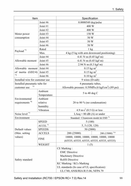
1. Safety
Safety and Installation (RC700 / EPSON RC+ 7.0) Rev.14 99
Item Specification Joint #6 0.0000549 deg/pulse
Motor power consumption
Joint #1 400 W Joint #2 400 W Joint #3 150 W Joint #4 50 W Joint #5 50 W Joint #6 50 W
Payload *3 Rated 1 kg Max. 4 kg (5 kg with arm downward positioning)
Allowable moment Joint #4 4.41 N·m (0.45 kgf·m) Joint #5 4.41 N·m (0.45 kgf·m) Joint #6 2.94 N·m (0.3 kgf·m)
Allowable moment of inertia (GD2/4) *4
Joint #4 0.15 kg·m2 Joint #5 0.15 kg·m2 Joint #6 0.10 kg·m2
Installed wire for customer use 9 wires (D-sub) Installed pneumatic tube for customer use *5
4 pneumatic tubes, Allowable pressure: 0.59MPa (6 kgf/cm2) (89 psi)
Environmental requirements *6
Ambient Temperature
5 to 40 deg C
Ambient relative humidity
20 to 80 % (no condensation)
Vibration 4.9 m⋅s2 (0.5 G) or less Noise level *7 LAeq = 80 dB (A) or under Environment Standard / Cleanroom model & ESD *8
Default values (Max. setting values)
SPEED 5 (100) ACCEL *9 5, 5 (120, 120) SPEEDS 50 (2000) ACCELS 200 (25000) 200 (15000) *10
FINE 10000, 10000, 10000, 10000, 10000, 10000
(65535, 65535, 65535, 65535, 65535, 65535) WEIGHT 1 (5)
Safety standard
CE Marking : EMC Directive Machinery Directive RoHS Directive
KC Marking / KCs Marking UL standards (In case of UL specification):
UL1740, ANSI/RIA R15.06, NFPA 79

1. Safety
100 Safety and Installation (RC700 / EPSON RC+ 7.0) Rev.14
*1: Manipulators are set to “Table Top mounting” at shipment. To use the manipulators as “Ceiling mounting”, you need to change the model settings. For details on how to change the model settings, refer to 5.5 Changing the Robot, and EPSON RC+ User’s Guide Robot Configuration.
*2: In case of PTP control *3: If the payload exceeds the maximum payload, refer to the section “Restrictions on payload
exceeding the maximum payload” in Setup & Operation 4.3.1 WEIGHT Setting. *4: If the center of gravity is at the center of each arm. If the center of gravity is not at the
center of each arm, set the eccentric quantity using INERTIA command. *5: For details of the installed pneumatic tube for customer use, refer to the Setup &
Operation 3.6 User Wires and Pneumatic Tubes. *6: For details of the environmental requirements, refer to the Setup & Operation 3.1
Environmental Conditions. *7: Conditions of Manipulator at measurement are as follows:
Operating conditions: Under rated load, 6 arms simultaneous motion, maximum speed, maximum acceleration, and duty 50%.
Measurement point: 1000 mm apart from the rear of Manipulator *8: The exhaust system in the Cleanroom-model Manipulator draws air from the base interior
and arm cover interior. A crack or other opening in the base unit can cause loss of negative air pressure in the outer part of the arm, which can cause increased dust emission. Do not remove the covers. Seal the exhaust port and the exhaust tube with vinyl tape so that the joint is airtight. If the exhaust flow is not sufficient, dust particle emission may exceed the specified maximum level. Cleanliness level : Class ISO 3 (ISO14644-1) Exhaust System : Fitting for ø8 mm pneumatic tube
Refer to Setup & Operation: 3.6 User Wires and Pneumatic Tubes. 60 L/min vacuum
Exhaust tube : Polyurethane tube Outer diameter: ø8 mm (Inner diameter: ø5 to 6 mm)
ESD specification uses resin materials with antistatic treatment. This model controls adhesion of dust due to electrification.
*9: In general use, Accel setting 100 is the optimum setting that maintains the balance of acceleration and vibration when positioning. Although values larger than 100 can be set to Accel, it is recommended to minimize the use of large values to necessary motions since operating the manipulator continuously with the large Accel setting may shorten the product life remarkably.
*10: Maximum AccelS setting value for payload of 4 kg or more is 12000. Although setting the value exceeding 12000 does not cause an error, do not set the value in order to prevent manipulator malfunction.

1. Safety
Safety and Installation (RC700 / EPSON RC+ 7.0) Rev.14 101
C8 Item Specification
Model Number C8-A701*** C8-A901*** C8-A1401*** Model Name C8 C8L C8XL Mounting type *1 Table Top mounting, Ceiling mounting, Wall mounting Weight (not include the weight of cables or shipping jigs)
Standard model, Cleanroom & ESD model
49 kg (108 lb.) 52 kg (115 lb.) 62 kg (137 lb.)
Protection model 53 kg (117 lb.) 56 kg (123 lb.) 66 kg (146 lb.) Driving method All joints AC servo motor
Max. operating speed *2
Joint #1 331 deg/s 294 deg/s 200 deg/s Joint #2 332 deg/s 300 deg/s 167 deg/s Joint #3 450 deg/s 360 deg/s 200 deg/s Joint #4 450 deg/s Joint #5 450 deg/s Joint #6 720 deg/s
Maximum synthetic speed 8958 mm/s 9679 mm/s 8858 mm/s Repeatability Joint #1 ~ #6 ± 0.02 mm ± 0.03 mm ± 0.05 mm
Max. motion range
Joint #1 ± 240 deg
Joint #2 − 158 deg ~ + 65 deg
− 158 deg ~ + 65 deg
− 135 deg ~ + 55 deg
Joint #3 − 61 deg ~ + 202 deg Joint #4 ± 200 deg Joint #5 ± 135 deg Joint #6 ± 360 deg
Max. pulse range (pulse)
Joint #1 ± 9507090 ± 10695600 ± 15736800
Joint #2 − 6245685 ~ + 2569428
− 6903178 ~ + 2839915
− 10616940 ~ + 4325420
Joint #3 − 1776754 ~ + 5883677
− 2220949 ~ + 7354618
− 3997696 ~ + 13238272
Joint #4 ± 5461400 Joint #5 ± 3932280 Joint #6 ± 6553800
Resolution (deg/pulse)
Joint #1 0.0000252 0.0000224 0.0000153 Joint #2 0.0000253 0.0000229 0.0000127 Joint #3 0.0000343 0.0000275 0.0000153 Joint #4 0.0000366 Joint #5 0.0000343 Joint #6 0.0000549
Motor power consumption
Joint #1 1000 W Joint #2 750 W Joint #3 400 W Joint #4 100 W Joint #5 100 W Joint #6 100 W
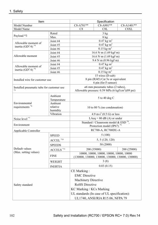
1. Safety
102 Safety and Installation (RC700 / EPSON RC+ 7.0) Rev.14
Item Specification Model Number C8-A701** C8-A901** C8-A1401** Model Name C8 C8L C8XL
Payload *3 Rated 3 kg Max. 8 kg
Allowable moment of inertia (GD2/4) *4
Joint #4 0.47 kg·m2 Joint #5 0.47 kg·m2 Joint #6 0.15 kg·m2
Allowable moment Joint #4 16.6 N·m (1.69 kgf·m) Joint #5 16.6 N·m (1.69 kgf·m) Joint #6 9.4 N·m (0.96 kgf·m)
Allowable moment of inertia (GD2/4) *4
Joint #4 0.47 kg·m2 Joint #5 0.47 kg·m2 Joint #6 0.15 kg·m2
Installed wire for customer use 15 wires (D-sub)
8 pin (RJ45) Cat 5e or equivalent 6 pin (for F-sensor)
Installed pneumatic tube for customer use *5
ø6 mm pneumatic tubes (2 tubes), Allowable pressure: 0.59 MPa (6 kgf/cm2)(89 psi)
Environmental requirements *6
Ambient Temperature 5 to 40 deg C
Ambient relative humidity
10 to 80 % (no condensation)
Vibration 4.9 m⋅s2 (0.5 G) or less Noise level *7 LAeq = 80 dB (A) or under
Environment Standard / Cleanroom model & ESD *8,
Protection model (IP67) *9 Applicable Controller RC700-A, RC700DU-A
Default values (Max. setting values)
SPEED 5 (100)
ACCEL *10 5, 5 (120, 120)
SPEEDS 50 (2000)
ACCELS *11 200 (35000) 200 (25000)
FINE 10000, 10000, 10000, 10000, 10000, 10000
(130000, 130000, 130000, 130000, 130000, 130000) WEIGHT 3 (8)
INERTIA 0.03 (0.15)
Safety standard
CE Marking : EMC Directive Machinery Directive RoHS Directive
KC Marking / KCs Marking UL standards (In case of UL specification):
UL1740, ANSI/RIA R15.06, NFPA 79

1. Safety
Safety and Installation (RC700 / EPSON RC+ 7.0) Rev.14 103
*1: Mounting types other than “Table Top mounting”, “Ceiling mounting”, and “Wall mounting” are out of specification. If you prefer other mounting types, please contact us.
*2: In case of PTP control.
*3: Do not apply the load exceeding the maximum payload.
*4: If the center of gravity is at the center of each arm. If the center of gravity is not at the center of each arm, set the eccentric quantity using INERTIA command.
*5: For details of the installed pneumatic tube for customer use, refer to the C8 series Manipulator Manual Setup & Operation 3.6 User Wires and Pneumatic Tubes.
*6: For details of the environmental requirements, refer to the C8 series Manipulator Manual Setup & Operation 3.1 Environmental Conditions.
*7: Conditions of Manipulator at measurement are as follows:
Operating conditions : Under rated load, 6 arms simultaneous motion, maximum speed, maximum acceleration, and C8, C8L:duty 50%., C8XL:duty 30%.
Measurement point : 1000 mm apart from the rear of Manipulator
*8: The exhaust system in the Cleanroom-model Manipulator draws air from the base interior and arm cover interior. A crack or other opening in the base unit can cause loss of negative air pressure in the outer part of the arm, which can cause increased dust emission. Do not remove the covers. Seal the exhaust port and the exhaust tube with vinyl tape so that the joint is airtight. If the exhaust flow is not sufficient, dust particle emission may exceed the specified maximum level.
Cleanliness level : C8, C8L ISO Class 3 (ISO14644-1) (Number of particles of 0.1 μm or larger in a sample air (28317 cm3: 1 cft) around the center of the motion area = less than 28 particles)
: C8XL ISO Class 4 (ISO14644-1) (Number of particles of 0.1 μm or larger in a sample air (28317 cm3: 1 cft) around the center of the motion area = less than 283 particles)

1. Safety
104 Safety and Installation (RC700 / EPSON RC+ 7.0) Rev.14
Exhaust System : Fitting for ø8 mm pneumatic tube Refer to C8 series Manipulator Manual Setup & Operation: 3.6 User Wires and Pneumatic Tubes. 60 L/min vacuum
Exhaust tube : Polyurethane tube Outer diameter: ø8 mm (Inner diameter: ø5 to 6 mm)
ESD specification uses resin materials with antistatic treatment. This model controls adhesion of dust due to electrification.
*9: Protection level for the protection-model Manipulators is IP67 (IEC standard). The Manipulators can be used in environments where the possibility of dust, water, and water-soluble cutting oil falling of the Manipulator exists. However, please be careful of the following:
- The Manipulator is not rust-proofed. Do not use the Manipulator in environment where corrosive liquids exist.
- Fluids that deteriorate the sealing materials, such as organic solvents, acids, alkalis, and chlorine cutting fluids, cannot be used
- The Manipulator cannot be used for underwater operations.
- The Controller does not have protection features against the environment (Controller’s protection level: IP20) Make sure to install the system where environmental requirements for the Controller are satisfied.
<Reference> - IP40 of IEC standard
[Protection level against ingress of solid objects] Protection from entry by solid objects with a diameter or thickness greater than 1.0 mm.
[Protection level against ingress of liquids] No protection
- IP67 of IEC standard [Protection level against ingress of solid objects]
Totally protected against dust. [Protection level against liquids]
Protection from ingress of water in harmful quantity when the Manipulator is immersed in water for 30 minutes under the condition that the highest point of the Manipulator is located 0.15 m below the surface of the water and the lowest point is located 1 m below the surface of the water. (Tested while the manipulator is stopped.)
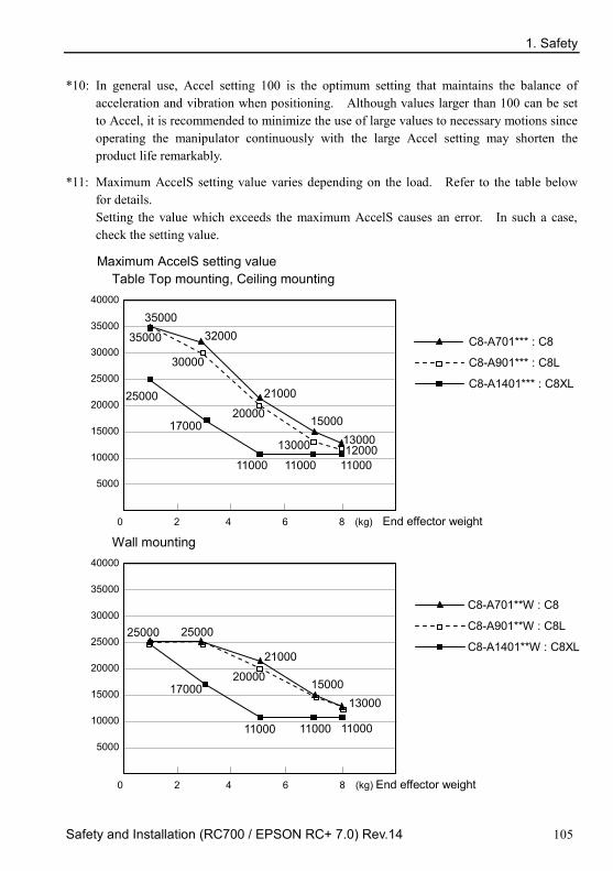
1. Safety
Safety and Installation (RC700 / EPSON RC+ 7.0) Rev.14 105
*10: In general use, Accel setting 100 is the optimum setting that maintains the balance of acceleration and vibration when positioning. Although values larger than 100 can be set to Accel, it is recommended to minimize the use of large values to necessary motions since operating the manipulator continuously with the large Accel setting may shorten the product life remarkably.
*11: Maximum AccelS setting value varies depending on the load. Refer to the table below for details. Setting the value which exceeds the maximum AccelS causes an error. In such a case, check the setting value.
Maximum AccelS setting value Table Top mounting, Ceiling mounting
40000
35000
30000
25000
20000
15000
10000
5000
0 2 4 6 8 (kg) End effector weight
30000
20000
35000
13000 12000
C8-A701*** : C8
C8-A901*** : C8L
C8-A1401*** : C8XL
17000
11000
25000
11000 11000
35000 32000
21000
15000 13000
Wall mounting
40000
35000
30000
25000
20000
15000
10000
5000
0 2 4 6 8 (kg) End effector weight
25000
20000
C8-A701**W : C8
C8-A901**W : C8L
C8-A1401**W : C8XL
17000
11000
25000
11000 11000
21000
15000 13000

1. Safety
106 Safety and Installation (RC700 / EPSON RC+ 7.0) Rev.14
N2 Item Specification
Model Number N2-A450SR N2-A450S
Model Name N2
Mounting type Ceiling mounting Table Top mounting *1 Weight (excluding cables) 19 kg (42 lb.) Driving method All joints AC servo motor
Max. operating speed *2
Joint #1 297°/s Joint #2 297°/s Joint #3 356°/s Joint #4 356°/s Joint #5 360°/s Joint #6 360°/s
Maximum synthetic speed 5772 mm/s Repeatability Joint #1 ~ #6 ± 0.02 mm
Max. motion range
Joint #1 ± 180° Joint #2 ± 180° Joint #3 ± 180° Joint #4 ± 195° Joint #5 ± 130° Joint #6 ± 360°
Max. pulse range
Joint #1 ± 7929856 Joint #2 ± 7929856 Joint #3 ± 6619136 Joint #4 ± 7170731 Joint #5 ± 4915200 Joint #6 ± 13107200
Resolution
Joint #1 0.0000227°/pulse Joint #2 0.0000227°/pulse Joint #3 0.0000272°/pulse Joint #4 0.0000272°/pulse Joint #5 0.0000275°/pulse Joint #6 0.0000275°/pulse
Motor power consumption
Joint #1 100 W Joint #2 100 W Joint #3 100 W Joint #4 30 W Joint #5 30 W Joint #6 15 W

1. Safety
Safety and Installation (RC700 / EPSON RC+ 7.0) Rev.14 107
Item Specification
Model Number N2-A450SR N2-A450S
Model Name N2
Payload *3 Rated 1 kg Max. 2.5 kg
Allowable moment Joint #4 5.4 N·m (0.55 kgf·m)
Joint #5 5.4 N·m (0.55 kgf·m)
Joint #6 2.4 N·m (0.24 kgf·m)
Allowable moment of inertia (GD2/4) *4
Joint #4 0.2 kg·m2
Joint #5 0.2 kg·m2
Joint #6 0.08 kg·m2
Installed wire for customer use 15 wires (D-sub)
8 pin (RJ45) Cat 5e or equivalent (2 cables) (also used for Force Sensor)
Installed pneumatic tube for customer use *5 ø6 mm pneumatic tubes (2 tubes), Allowable pressure: 0.59 MPa (6 kgf/cm2) (89 psi)
Environmental requirements *6
Ambient Temperature 5 to 40 deg C
Ambient relative humidity 10 to 80% (no condensation)
Vibration 4.9 m⋅s2 (0.5 G) or less Noise level *7 LAeq = 80 dB (A) or under
Default values (Max. setting values)
SPEED 5 (100) ACCEL *8 5, 5 (120, 120) SPEEDS 50 (1120) ACCELS 200 (5000)
FINE 10000, 10000, 10000, 10000, 10000, 10000
(65000, 65000, 65000, 65000, 65000, 65000) WEIGHT 1 (2.5) INERTIA 0.005 (0.08)
Safety standard CE Marking : EMC Directive, Machinery Directive,
RoHS Directive KC Marking / KCs Marking
*1: Manipulators are set to “Ceiling mounting” at shipment. To use the manipulators as “Table Top mounting”, you need to change the model settings. Mounting types other than “Ceiling mounting” and “Table Top mounting” are out of specification. If you prefer other mounting types, please contact us. For details on how to change the model settings, refer to 5.4 Changing the Robot, and EPSON RC+ User’s Guide Robot Configuration.
*2: In case of PTP control
*3: Do not apply the load exceeding the maximum payload.

1. Safety
108 Safety and Installation (RC700 / EPSON RC+ 7.0) Rev.14
*4: If the center of gravity is at the center of each arm. If the center of gravity is not at the center of each arm, set the eccentric quantity using INERTIA command.
*5: For details of the installed pneumatic tube for customer use, refer to the Setup & Operation 3.7 User Wires and Pneumatic Tubes.
*6: For details of the environmental requirements, refer to the Setup & Operation 3.1 Environmental Conditions.
*7: Conditions of Manipulator at measurement are as follows:
Operating conditions: Under rated load, 6 arms simultaneous motion, maximum speed, maximum acceleration, and duty 50%.
Measurement point: 1000 mm apart from the rear of Manipulator
*8: In general use, Accel setting 100 is the optimum setting that maintains the balance of acceleration and vibration when positioning. Although values larger than 100 can be set to Accel, it is recommended to minimize the use of large values to necessary motions since operating the manipulator continuously with the large Accel setting may shorten the product life remarkably.
X5
For details, refer to EZ MODULES X5 series manual.

1. Safety
Safety and Installation (RC700 / EPSON RC+ 7.0) Rev.14 109
1.9 Motion Range Setting by Mechanical Stops
G1
Mechanical stop of Joint #2 (Adjustable)
Mechanical stop of Joint #3 (Lower limit mechanical stop)
(Do not move the upper limit mechanical stop.)
Mechanical stop of Joint #1 (Adjustable)
Joint #1
A C
B D
( ° = degree )
Model A B C D All +125° −125° +120° −120°

1. Safety
110 Safety and Installation (RC700 / EPSON RC+ 7.0) Rev.14
Joint #2
E C B
D
G1-171CZ
A D B C E
G1-221*
D B C E
G1-171*
Top Bottom Top
( ° = degree ) Model A B *1 C *1 D E
4-axis spec
G1-171S - +140° −140° +130° −130° G1-171C - +140° −140° +130° −130° G1-221S ±152° +140° −140° +125° −125° G1-221C ±149° +140° −140° +125° −125°
3-axis spec
G1-171SZ - +135° −135° +125° −125° G1-171CZ *2 - +123° −123° +115° −115° G1-221SZ - +135° −135° +120° −120° G1-221CZ - +132° −132° +120° −120°
*1 Standard position of the mechanical stop
*2 Limits the motion range using the bolts in the Arm #2 bottom to prevent the bellows from contacting the manipulator body.

1. Safety
Safety and Installation (RC700 / EPSON RC+ 7.0) Rev.14 111
G3
Table Top Mounting
Mechanical stop of Joint #2 (Fixed)
Mechanical stop of Joint #1 (Adjustable)
Mechanical stop of Joint #3 (Lower limit mechanical stop)
(Do not move the upper limit mechanical stop.)
Mechanical stop of Joint #1 (Fixed)
Mechanical stop of Joint #2 (Adjustable)
Multiple Mounting
Mechanical stop of Joint #1 (Adjustable)
Mechanical stop of Joint #1 (Fixed)
* The different mechanical stop positions from Table Top mounting are
indicated for Multiple mounting.
Install the bolts for the mechanical stop of Joint #1 (adjustable) to the following position.
Table Top mounting : Arm bottom side
Multiple mounting : Arm top side

1. Safety
112 Safety and Installation (RC700 / EPSON RC+ 7.0) Rev.14
R L
Joint #1 Mechanical Stops
Views from the bottom of Arm #1
Model Arm a b c
G3-**1S, C 250 ±140° -110° +110° 300 ±140° -110° +110° 350 ±140° -110° +110°
G3-**1S, C-R 300 -125° ~ +150° -105° +130° 350 -110° ~ +165° -90° +145°
G3-**1S, C-L 300 -150° ~ +125° -130° +105° 350 -165° ~ +110° -145° +90°
G3-**1SM, CM 300 ±115° -100° +100° 350 ±120° -105° +105°
G3-351SM, CM-R 350 -105° ~ +130° -95° +120° G3-351SM, CM-L 350 -130° ~ +105° -120° +95°
Setting Angle +90° +95° +100° +105° +110° +115° +120° Pulse Value 5242880 5388516 5534151 5679787 5825423 5971058 6116694
Setting Angle +125° +130° +140° +145° +150° +165° Pulse Value 6262329 6407965 6699236 6844872 6990507 7427414
Setting Angle -90° -95° -100° -105° -110° -115 -120° Pulse Value 0 -145636 -291271 -436907 -582542 -728178 -873813
Setting Angle -125° -130° -140° -145° -150° +165° Pulse Value -1019449 -1165085 -1456356 -1601991 -1747627 -2184533
(°: degree)
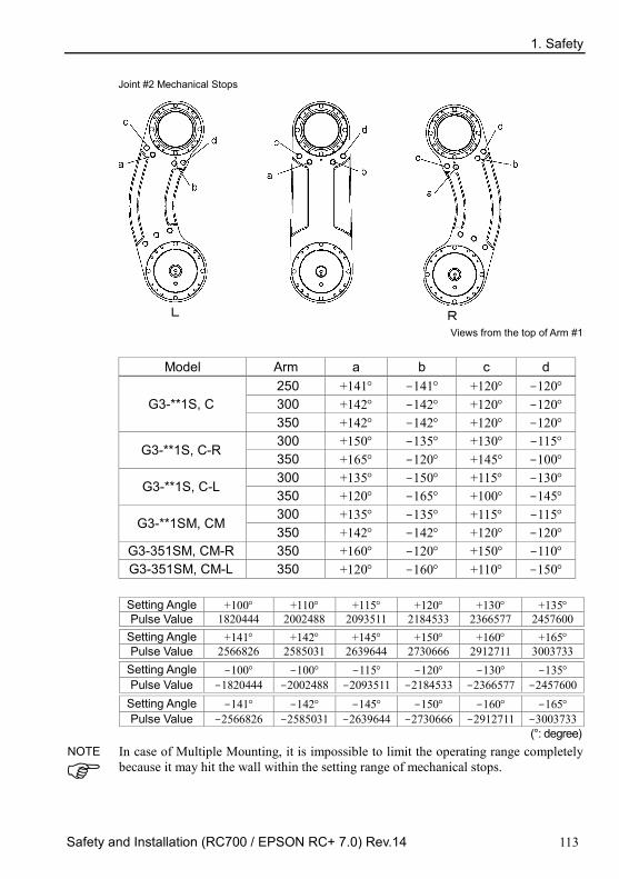
1. Safety
Safety and Installation (RC700 / EPSON RC+ 7.0) Rev.14 113
R L
Joint #2 Mechanical Stops
Views from the top of Arm #1
Model Arm a b c d
G3-**1S, C 250 +141° -141° +120° -120° 300 +142° -142° +120° -120° 350 +142° -142° +120° -120°
G3-**1S, C-R 300 +150° -135° +130° -115° 350 +165° -120° +145° -100°
G3-**1S, C-L 300 +135° -150° +115° -130° 350 +120° -165° +100° -145°
G3-**1SM, CM 300 +135° -135° +115° -115° 350 +142° -142° +120° -120°
G3-351SM, CM-R 350 +160° -120° +150° -110° G3-351SM, CM-L 350 +120° -160° +110° -150°
Setting Angle +100° +110° +115° +120° +130° +135° Pulse Value 1820444 2002488 2093511 2184533 2366577 2457600
Setting Angle +141° +142° +145° +150° +160° +165° Pulse Value 2566826 2585031 2639644 2730666 2912711 3003733
Setting Angle -100° -100° -115° -120° -130° -135° Pulse Value -1820444 -2002488 -2093511 -2184533 -2366577 -2457600
Setting Angle -141° -142° -145° -150° -160° -165° Pulse Value -2566826 -2585031 -2639644 -2730666 -2912711 -3003733
(°: degree) In case of Multiple Mounting, it is impossible to limit the operating range completely because it may hit the wall within the setting range of mechanical stops.
NOTE

1. Safety
114 Safety and Installation (RC700 / EPSON RC+ 7.0) Rev.14
G6
Table Top Mounting
Mechanical stop of Joint #2 (Adjustable)
Mechanical stop of Joint #1 (Fixed)
Mechanical stop of Joint #3 (Lower limit mechanical stop)
(Do not move the upper limit mechanical stop.)
Mechanical stop of Joint #1 (Adjustable)
Mechanical stop of Joint #2 (Fixed)
Wall Mounting
Mechanical stop of Joint #1 (Fixed) Mechanical stop of Joint #1 (Adjustable)
Ceiling Mounting
Mechanical stop of Joint #1 (Fixed) Mechanical stop of Joint #1 (Adjustable)
* The different mechanical stop positions from Table Top mounting are indicated for Wall mounting and Ceiling mounting.

1. Safety
Safety and Installation (RC700 / EPSON RC+ 7.0) Rev.14 115
a b
c
d
e f g h
i
j
k l
Joint #1 Mechanical Stops
Joint #1
Mounting Arm Length a b c d e f Table Top 45, 55, 65 +152° +135°
+105° +60° +20° +5°
Ceiling 55, 65
Wall 65 +148° 55 +135°
Ceiling 45 +120° +75° +30° Wall 45
Mounting Arm Length g h i j k l Table Top 45, 55, 65
-5° -20° -60° -105°
-135° -152° Ceiling 55, 65
Wall 65 -148° 55 -135°
Ceiling 45 -30° -75° -120°
Wall 45
Setting Angle +152° +148° +135° +120° +105° +75° +60° Pulse Value 7048761 6932253 6553600 6116694 5679787 4805974 4369067
Setting Angle +30° +20° +5° -5° -20° -30° -60° Pulse Value 3495254 3203983 2767076 2475805 2038898 1747627 873814
Setting Angle -75° -105° -120° -135° -148° -152° Pulse Value 436907 -436907 -873814 -1310720 -1689373 -1805881
(°: degree)

1. Safety
116 Safety and Installation (RC700 / EPSON RC+ 7.0) Rev.14
q p
o
n
m
Joint #2 Mechanical Stops
Joint #2
Model Arm Length m n o p q Table Top, Ceiling, Wall 55, 65
+100° +125°
+147.5°
-125° -100° Table Top
G6-45*S, D 45 (Z : 0 to –270) 45 (Z :–270 to –330) +145°
G6-45*C, P, D bellows
45 (Z : 0 to –240) +147.5° 45 (Z :–240 to –300) +142°
Ceiling, Wall 45 +130° The bellows for G6-***D* are options at shipment.
Setting Angle +147.5° +145° +142° +130° +125° +100° Pulse Value 2685156 2639645 2585031 2366578 2275556 1820445
Setting Angle -100° -125° -130° -142° -145° -147.5° Pulse Value -1820445 -2275556 -2366578 -2585031 -2639644 -2685156
(°: degree)

1. Safety
Safety and Installation (RC700 / EPSON RC+ 7.0) Rev.14 117
G10/G20
Table Top Mounting
Mechanical stop of Joint #2 (Adjustable)
Mechanical stop of Joint #1 (Fixed)
Mechanical stop of Joint #3 (Lower limit mechanical stop)
(Do not move the upper limit mechanical stop.)
Mechanical stop of Joint #1 (Adjustable)
Mechanical stop of Joint #2 (Fixed)
Wall Mounting
Mechanical stop of Joint #1 (Fixed)
Mechanical stop of Joint #1 (Adjustable)
Ceiling Mounting
Mechanical stop of Joint #1 (Fixed)
Mechanical stop of Joint #1 (Adjustable)
* The different mechanical stop positions from Table Top Mounting are indicated for Wall Mounting and Ceiling Mounting.

1. Safety
118 Safety and Installation (RC700 / EPSON RC+ 7.0) Rev.14
a
b
c
d e
f
g
h
Joint #1 Mechanical Stops
Joint #1
Mounting Arm Length a b c d e f g h Table Top 65, 85, A0 +152°
+107° +60° +15° -15° -60° -107° -152°
Ceiling 85, A0 Ceiling 65
Wall 65, 85, A0
a b c d e f g h Setting Angle +152° +107° +60° +15° -15° -60° -107° -152°
Pulse Value +7048761 +5738041 +4369067 +3058347 +2184534 +873814 -495161 -1805881
(°: degree)

1. Safety
Safety and Installation (RC700 / EPSON RC+ 7.0) Rev.14 119
Joint #2 Mechanical Stops
p o n
m
Joint #2
Model Arm Length m n o q
Table Top, Ceiling, Wall A0
+122.5° +152.5° -152.5° -122.5° Table Top
G10/G20 -85*S, D 85
G10/G20 -85*C, P, D bellows
85 Z: 0 to –360
Z: –360 to –390 +121° +151° -151° -121°
Ceiling, Wall
G10/G20 -85*SR, SW, DR, DW
85 +122.5° +152.5° -152.5° -122.5°
G10/G20 -85*CR, CW, PR, PW, DR bellows, DW bellows
85 +100° +130° -130° -100°
Table Top 65 +122.5° +152.5° -152.5° -122.5° Ceiling, Wall 65 +100° +130° -130° -100°
The bellows for G10/G20-***D* are options at shipment.
Setting Angle +100° +121° +122.5° +151° +152.5° Pulse Value +1820445 +2202738 +2230045 +2748871 +2776178
Setting Angle -152.5° -151° -122.5° -121° -100° Pulse Value -2776178 -2748871 -2230045 -2202738 -1820445
(°: degree)
In the range Z: –360 to –390 mm, the area is limited by interference of the
Manipulator body and the arm.
NOTE

1. Safety
120 Safety and Installation (RC700 / EPSON RC+ 7.0) Rev.14
C4 Mechanical stops physically limit the absolute area that the Manipulator can move.
Be sure to turn OFF the Controller in advance.
Bolts are not provided, arrange for them by yourself.
Use bolts conforming to the strength specified by ISO-898-1, property class: 12.9.
Specify the pulse range again after changing the position of the mechanical stop.
For details on the pulse range setting, refer to the C4 series Manipulator manual Setup & Operation 5.1 Motion Range Setting by Pulse Range (for All Arms).
Be sure to set the pulse range not to exceed the setting angles of the mechanical stop.
Motion Range Setting of Arm #1 Install the bolt to the threaded hole corresponding to the angle you want to set.
Normally a mechanical stop is equipped at [ b ].
[ a ] and [ c ] limit the one side of motion range.
Remove the bolts when the motion range of the Arm #1 is set to ±180 deg.
M8×15 hexagon socket head cap bolt Tightening torque: 37.2 N·m (380 kgf·cm)
a
b
c
a b c Angle (deg) −125 ±170 ±180 +125
Pulse (pulse)
C4-A601** −3640889 ±4951609 ±5242880 +3640889 C4-A901**
−5957819 ±8102633
±8579259 +5957819 C4-A901**-UL ±7626008
Bolt Applied Applied (Normal) Not applied Applied
Mechanical stop for UL specification There is a specified mechanical stop for UL specification. Mount the mechanical stop as shown in the figure below.
C4
C4L The setting angle differs from the non-UL compliant model. (refer to the above table)
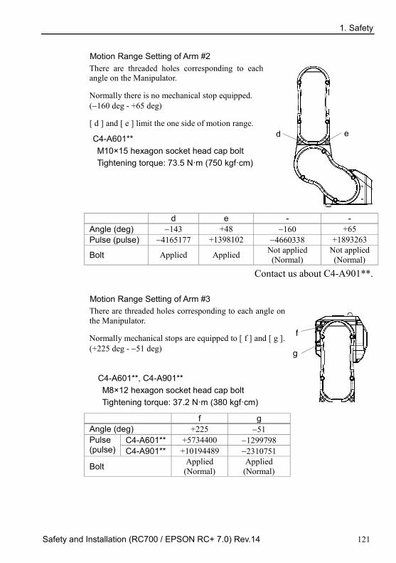
1. Safety
Safety and Installation (RC700 / EPSON RC+ 7.0) Rev.14 121
Motion Range Setting of Arm #2 There are threaded holes corresponding to each angle on the Manipulator.
Normally there is no mechanical stop equipped. (−160 deg - +65 deg)
[ d ] and [ e ] limit the one side of motion range.
C4-A601** M10×15 hexagon socket head cap bolt Tightening torque: 73.5 N·m (750 kgf·cm)
e d
d e - - Angle (deg) −143 +48 −160 +65 Pulse (pulse) −4165177 +1398102 −4660338 +1893263
Bolt Applied Applied Not applied (Normal)
Not applied (Normal)
Contact us about C4-A901**.
Motion Range Setting of Arm #3 There are threaded holes corresponding to each angle on the Manipulator.
Normally mechanical stops are equipped to [ f ] and [ g ]. (+225 deg - −51 deg)
C4-A601**, C4-A901** M8×12 hexagon socket head cap bolt Tightening torque: 37.2 N·m (380 kgf·cm)
g
f
f g Angle (deg) +225 −51 Pulse (pulse)
C4-A601** +5734400 −1299798 C4-A901** +10194489 −2310751
Bolt Applied (Normal)
Applied (Normal)
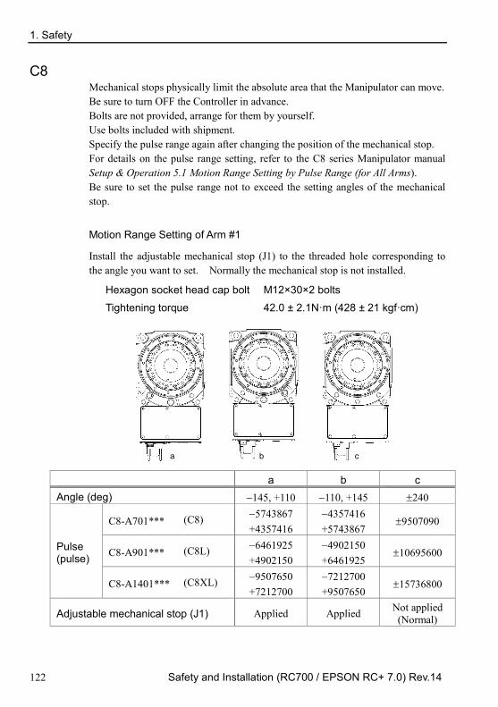
1. Safety
122 Safety and Installation (RC700 / EPSON RC+ 7.0) Rev.14
C8 Mechanical stops physically limit the absolute area that the Manipulator can move. Be sure to turn OFF the Controller in advance. Bolts are not provided, arrange for them by yourself. Use bolts included with shipment. Specify the pulse range again after changing the position of the mechanical stop. For details on the pulse range setting, refer to the C8 series Manipulator manual Setup & Operation 5.1 Motion Range Setting by Pulse Range (for All Arms). Be sure to set the pulse range not to exceed the setting angles of the mechanical stop.
Motion Range Setting of Arm #1
Install the adjustable mechanical stop (J1) to the threaded hole corresponding to the angle you want to set. Normally the mechanical stop is not installed.
Hexagon socket head cap bolt M12×30×2 bolts
Tightening torque 42.0 ± 2.1N·m (428 ± 21 kgf·cm)
a b c
a b c Angle (deg) −145, +110 −110, +145 ±240
Pulse (pulse)
C8-A701*** (C8) −5743867 +4357416
−4357416 +5743867
±9507090
C8-A901*** (C8L) −6461925 +4902150
−4902150 +6461925
±10695600
C8-A1401*** (C8XL) −9507650 +7212700
−7212700 +9507650
±15736800
Adjustable mechanical stop (J1) Applied Applied Not applied (Normal)
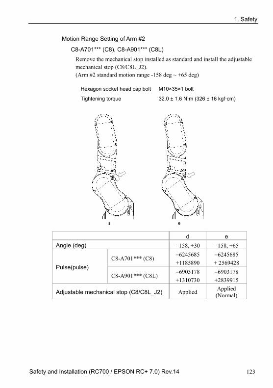
1. Safety
Safety and Installation (RC700 / EPSON RC+ 7.0) Rev.14 123
Motion Range Setting of Arm #2
C8-A701*** (C8), C8-A901*** (C8L) Remove the mechanical stop installed as standard and install the adjustable mechanical stop (C8/C8L_J2). (Arm #2 standard motion range -158 deg ~ +65 deg)
Hexagon socket head cap bolt M10×35×1 bolt
Tightening torque 32.0 ± 1.6 N·m (326 ± 16 kgf·cm)
d e
d e Angle (deg) −158, +30 −158, +65
Pulse(pulse) C8-A701*** (C8)
−6245685 +1185890
−6245685 + 2569428
C8-A901*** (C8L) −6903178 +1310730
−6903178 +2839915
Adjustable mechanical stop (C8/C8L_J2) Applied Applied (Normal)
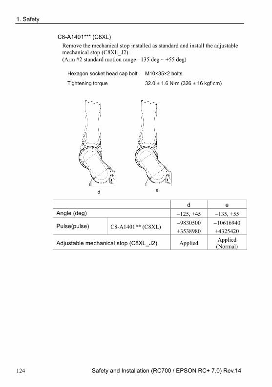
1. Safety
124 Safety and Installation (RC700 / EPSON RC+ 7.0) Rev.14
C8-A1401*** (C8XL) Remove the mechanical stop installed as standard and install the adjustable mechanical stop (C8XL_J2). (Arm #2 standard motion range −135 deg ~ +55 deg)
Hexagon socket head cap bolt M10×35×2 bolts
Tightening torque 32.0 ± 1.6 N·m (326 ± 16 kgf·cm)
d e
d e Angle (deg) −125, +45 −135, +55
Pulse(pulse) C8-A1401** (C8XL) −9830500 +3538980
−10616940 +4325420
Adjustable mechanical stop (C8XL_J2) Applied Applied (Normal)
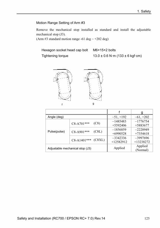
1. Safety
Safety and Installation (RC700 / EPSON RC+ 7.0) Rev.14 125
Motion Range Setting of Arm #3
Remove the mechanical stop installed as standard and install the adjustable mechanical stop (J3). (Arm #3 standard motion range -61 deg ~ +202 deg)
Hexagon socket head cap bolt M6×15×2 bolts
Tightening torque 13.0 ± 0.6 N·m (133 ± 6 kgf·cm)
f g
f g Angle (deg) −51, +192 −61, +202
Pulse(pulse)
C8-A701*** (C8) −1485483 +5592406
−1776754 +5883677
C8-A901*** (C8L) −1856859 +6990528
−2220949 +7354618
C8-A1401*** (C8XL) −3342336 +12582912
−3997696 +13238272
Adjustable mechanical stop (J3) Applied Applied (Normal)

1. Safety
126 Safety and Installation (RC700 / EPSON RC+ 7.0) Rev.14
1.10 End User Training Persons in charge of safety management should confirm that the operators who program, operate, and maintain the robot and robot system take proper training and have expertise to conduct the work safely. Training should include at least the following:
- Study of regulation safety procedures, and safety-related recommendations by robot manufacturers and system designers.
- Clear explanation of the work involved.
- Description of all control equipment required for the work and their functions.
- Explanation of potential hazards involved in the work.
- Work safety procedures and specific methods of avoiding potential hazards.
- Safety device and interlock function testing and confirmation methods are working properly.

2. Installation
Safety and Installation (RC700 / EPSON RC+ 7.0) Rev.14 127
2. Installation This chapter contains precautions for safe and accurate installation of the robot system. The workflow for installing the robot system is described in 2.1 Outline from Unpacking to Operation of Robot System. For unpacking, transportation, and installation, refer to the respective section and the Manipulator and Controller manuals.

2. Installation
128 Safety and Installation (RC700 / EPSON RC+ 7.0) Rev.14
System Example
Control Unit only
Operation Panel
Motion Controller
RC700 / RC700-A
Expansion I/O Board
Fieldbus PROFIBUS-DP DeviceNet CC-Link EtherNet/IP PROFINET EtherCAT
RS-232C Board
Windows *1
PC
EPSON RC+ 7.0 software
USB2.0 or Ethernet
TP2 (option)
- Standard I/O - Remote I/O - Ethernet - RS-232C
Requires preparation by uses
PLC (Sequencer)
Option
Standard
TP1 (option)
C4 series C8 series
G series
RS series
* 2
* 3
* 4
TP3 (option)
N series
* 4
Option
X5 series
Analog I/O Board
PG Board
Force Sensor I/F Board

2. Installation
Safety and Installation (RC700 / EPSON RC+ 7.0) Rev.14 129
*1 EPSON RC+ 7.0 supports the following OS. Windows XP Professional Service Pack 3
(EPSON RC+ 7.0 Ver. 7.2.0 or earlier) Windows Vista Business Service Pack 2 Windows 7 Professional Service Pack 1 Windows 8.1 Pro (EPSON RC+ 7.0 Ver.7.1.0 or later) Windows 10 Pro (EPSON RC+ 7.0 Ver.7.2.0 or later)
*2 Any one of the manipulators can be controlled. Available combinations are as follows. (: connectable)
C4 C8 G RS N X5 RC700 - - - - - RC700-A
*3 Any one of the Teach pendant can be controlled. TP3 cannot be connected to RC700.
*4 When connecting to RC700-A, a dedicated conversion cable is required.

2. Installation
130 Safety and Installation (RC700 / EPSON RC+ 7.0) Rev.14
Control Unit and Drive Unit
RC700 / RC700-A
RC700DU / RC700DU-A
・EMERGENCY ・Standard I/O ・Remote I/O ・R-I/O
Standard Installation
C4 series C8 series
G series
RS series
* 1
X5
*1 Any one of the manipulators can be controlled.
Available combinations are as follows. (: connectable) C4 C8 G RS N X5 RC700DU - - - - - RC700DU-A -

2. Installation
Safety and Installation (RC700 / EPSON RC+ 7.0) Rev.14 131
Drive Unit is the auxiliary unit connected with the control unit using the special
cable.
Drive Unit cannot operate alone.
Up to three Drive Units can be used per robot system.
A: Control Unit and 1st Drive Unit (CU-DU1)
B: 1st Drive Unit and 2nd Drive Unit (DU1-DU2)
C: 2nd Drive Unit and 3rd Drive Unit (DU2-DU3)
DU2
B A
DU IN
DU1
CU
DU IN DU OUT DU OUT
DU3
C
DU IN DU OUT
NOTE

2. Installation
132 Safety and Installation (RC700 / EPSON RC+ 7.0) Rev.14
2.1 Outline from Unpacking to Operation of Robot System
Transportation
Unpacking
Error?
Installation
Power-on
Yes
No
Procedures to install EPSON RC+ to the development PC and enable the operation of the robot system
Manual information to connect or setup the equipment and options
2. Installation
Procedures to install the Robot system and turn ON the power properly
4. Second Step
3. First Step

2. Installation
Safety and Installation (RC700 / EPSON RC+ 7.0) Rev.14 133
2.2 Unpacking Installation and transportation of robots and robotic equipment shall be performed by qualified personnel and should conform to all national and local codes.
Using a cart or similar equipment, transport the Manipulator in the same conditions as it was delivered. Observe the following when unpacking the Manipulator.
2.2.1 Unpacking Precautions
Transportation procedure
: Only authorized personnel should perform sling work and operate a crane or forklift. When these operations are performed by unauthorized personnel, it is extremely hazardous and may result in serious bodily injury and/or severe equipment damage to the robot system.
Vibration at transportation
: Avoid excessive vibration or shock during Manipulator transporting. Excessive vibration or shock may cause equipment damage to and/or malfunction of the Manipulator.
Anchor bolt
: When removing the anchor bolts, support the Manipulator to prevent falling. Removing the anchor bolts without supporting the Manipulator may get hands, fingers, or feet caught as the Manipulator will fall.
Wire tie
: Do not remove the wire tie securing the arm until you finish the installation. You may get your hands caught in the Manipulator when the wire tie is removed before completing the installation.

2. Installation
134 Safety and Installation (RC700 / EPSON RC+ 7.0) Rev.14
2.3 Transportation Installation and transportation of robots and robotic equipment shall be performed by qualified personnel and should conform to all national and local codes.
2.3.1 Transportation Precautions
Transportation procedure
: Using a cart or similar equipment, transport the Manipulator in the same
conditions as it was delivered. Observe the following when unpacking the Manipulator. Only authorized personnel should perform sling work and operate a crane or forklift. When these operations are performed by unauthorized personnel, it is extremely hazardous and may result in serious bodily injury and/or severe equipment damage to the robot system.
Vibration at transportation
: Avoid excessive vibration or shock during Manipulator transporting. Excessive vibration or shock may cause equipment damage to and/or malfunction of the Manipulator.
Anchor bolt
: When removing the anchor bolts, support the Manipulator to prevent falling. Removing the anchor bolts without supporting the Manipulator may get hands, fingers, or feet caught as the Manipulator will fall.
Wire tie
: Do not remove the wire tie securing the arm until you finish the installation. You may get your hands caught in the Manipulator when the wire tie is removed before completing the installation.
Hoisting procedure
: Stabilize the Manipulator with your hands when hoisting it. Unstable hoisting is extremely hazardous and may results in serious bodily injury and/or severe equipment damage to the robot system as the fall of the Manipulator.
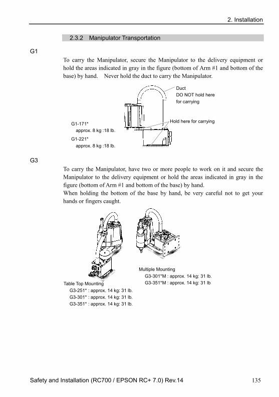
2. Installation
Safety and Installation (RC700 / EPSON RC+ 7.0) Rev.14 135
2.3.2 Manipulator Transportation
G1 To carry the Manipulator, secure the Manipulator to the delivery equipment or hold the areas indicated in gray in the figure (bottom of Arm #1 and bottom of the base) by hand. Never hold the duct to carry the Manipulator.
G1-221* approx. 8 kg :18 lb.
Duct DO NOT hold here for carrying
Hold here for carrying G1-171* approx. 8 kg :18 lb.
G3 To carry the Manipulator, have two or more people to work on it and secure the Manipulator to the delivery equipment or hold the areas indicated in gray in the figure (bottom of Arm #1 and bottom of the base) by hand. When holding the bottom of the base by hand, be very careful not to get your hands or fingers caught.
Table Top Mounting G3-251* : approx. 14 kg: 31 lb. G3-301* : approx. 14 kg: 31 lb. G3-351* : approx. 14 kg: 31 lb.
Multiple Mounting G3-301*M : approx. 14 kg: 31 lb. G3-351*M : approx. 14 kg: 31 lb

2. Installation
136 Safety and Installation (RC700 / EPSON RC+ 7.0) Rev.14
G6 To carry the Manipulator, have two or more people to work on it and secure the Manipulator to the delivery equipment or hold the areas indicated in gray in the figure (bottom of Arm #1 / bottom of the base) by hand. When holding the bottom of the base by hand, be very careful not to get hands or fingers caught.
Wall Mounting G6-45**W, G6-55**W
Approx. 29 kg: 64 lb. G6-65**W
Approx. 29.5 kg: 65 lb.
Ceiling Mounting G6-45**R, G6-55**R
Approx. 27 kg: 60 lb. G6-65**R
Approx. 28 kg: 62 lb.
Table Top Mounting G6-45**, G6-55**
Approx. 27 kg: 60 lb. G6-65**
Approx. 28 kg: 62 lb.
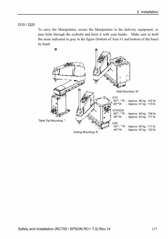
2. Installation
Safety and Installation (RC700 / EPSON RC+ 7.0) Rev.14 137
G10 / G20 To carry the Manipulator, secure the Manipulator to the delivery equipment, or pass belts through the eyebolts and hoist it with your hands. Make sure to hold the areas indicated in gray in the figure (bottom of Arm #1 and bottom of the base) by hand.
Table Top Mounting: *
Wall Mounting: W
Ceiling Mounting: R
G10 65**, **R : Approx. 46 kg : 102 lb 65**W : Approx. 51 kg : 113 lb
G10/G20 85**, **R : Approx. 48 kg : 106 lb 85**W : Approx. 53 kg : 117 lb
G20 A0**, **R : Approx. 50 kg : 111 lb A0**W : Approx. 55 kg : 122 lb
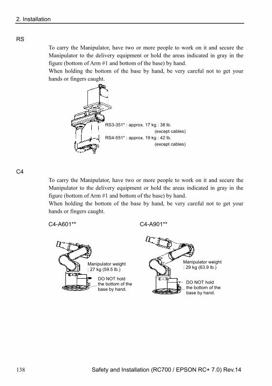
2. Installation
138 Safety and Installation (RC700 / EPSON RC+ 7.0) Rev.14
RS To carry the Manipulator, have two or more people to work on it and secure the Manipulator to the delivery equipment or hold the areas indicated in gray in the figure (bottom of Arm #1 and bottom of the base) by hand. When holding the bottom of the base by hand, be very careful not to get your hands or fingers caught.
RS3-351* : approx. 17 kg : 38 lb. (except cables) RS4-551* : approx. 19 kg : 42 lb. (except cables)
C4 To carry the Manipulator, have two or more people to work on it and secure the Manipulator to the delivery equipment or hold the areas indicated in gray in the figure (bottom of Arm #1 and bottom of the base) by hand. When holding the bottom of the base by hand, be very careful not to get your hands or fingers caught.
C4-A601**
Manipulator weight : 27 kg (59.5 lb.)
DO NOT hold the bottom of the base by hand.
C4-A901**
Manipulator weight : 29 kg (63.9 lb.)
DO NOT hold the bottom of the base by hand.

2. Installation
Safety and Installation (RC700 / EPSON RC+ 7.0) Rev.14 139
C8
To carry the Manipulator, secure it to the delivery equipment or have at least 2 people to hold it by hand. Also, do not hold the bottom of the base (the screened parts in the figure). Holding these parts by hand is extremely hazardous and may cause your hands and fingers caught.
Figure: C8-A901* (C8L) DO NOT hold the bottom of the base by hand
Manipulator weight C8-A701**: C8 C8-A901**: C8L C8-A1401** (C8XL) Standard, Clean-room model 49 kg : 108 lb. 52 kg : 115 lb. 62 kg :137 lb.
Protection model 53 kg : 117 lb. 56 kg : 123 lb. 66 kg : 146 lb.
N2
To carry the Manipulator, be sure to have at least 2 people to hold the bottom of the base or the Arm by hand. When holding the base installation face by hand, be careful not to cause your hands and fingers caught.
Manipulator weight: 19 kg: 42 lb

2. Installation
140 Safety and Installation (RC700 / EPSON RC+ 7.0) Rev.14
X5 Transport separately
Make sure not to apply ropes to the motor unit, secure the other part of body
instead when roping or transporting the manipulator.
Transport with multi-axis installed
To avoid colliding while transporting, use ropes or fittings to secure parts.
- Basically, transport the manipulator on module basis.
Module body weight
RH module Max. 61 kg RM module Max. 17 kg RSz module Max. 8.3 kg RU module 2.6 kg
Motor
Main unit

2. Installation
Safety and Installation (RC700 / EPSON RC+ 7.0) Rev.14 141
2.4 Manipulator Installation Installation and transportation of robots and robotic equipment shall be performed by qualified personnel and should conform to all national and local codes.
2.4.1 Installation Precautions
Safeguard installation
: To ensure safety, a safeguard must be installed for the robot system.
For details on the safeguard, refer to the Installation and Design Precautions in the Safety chapter of the EPSON RC+ User’s Guide.
Space between safeguard and Manipulator
: Install the Manipulator at a location with sufficient space so that a tool or a work piece on the end effector does not reach a wall or a safeguard when the Manipulator extends its arm fully while holding a work piece. Installing the Manipulator at a location with insufficient space is extremely hazardous and may result in serious bodily injury and/or severe equipment damage to the robot system as a tool or a work piece may collide with a wall and a safeguard.
Manipulator check before installation
: Before installing and operating the Manipulator, make sure that all parts of the Manipulator are in place and have no external defects. Missing or defective parts may cause improper operation of the Manipulator. Improper operation of the Manipulator is extremely hazardous and may result in serious bodily injury and/or severe equipment damage to the robot system.
Wall mounting and ceiling mounting
: When mounting the Manipulator on a wall or ceiling, secure the Manipulator to the wall or ceiling that has enough strength and rigidity. Mounting the Manipulator on a wall or ceiling that has insufficient strength and rigidity is extremely hazardous and may result in serious bodily injury and/or severe equipment damage to the robot system as the Manipulator may fall or vibrate.
Side mounting and ceiling mounting
: When mounting the Manipulator on a wall or ceiling, for safety purposes, attach the support to the Manipulator base to prevent the Manipulator from falling. If the Manipulator falls, it is extremely hazardous and may result in serious bodily injury and/or severe equipment damage to the robot system.

2. Installation
142 Safety and Installation (RC700 / EPSON RC+ 7.0) Rev.14
For Protected-model
: Connect the power cable connection and the signal cable connector to the Manipulator immediately after the Manipulator installation. The Manipulator without connecting them may result in electric shock and/or malfunction of the robot system as it cannot ensure IP65.
2.4.2 Environment
A suitable environment is necessary for the robot system to function properly and safely. Be sure to install the robot system in an environment that meets the following conditions:
Item Conditions Ambient temperature * 5 to 40°C (with minimum temperature variation) Ambient relative humidity 10 to 80% (no condensation) First transient burst noise 2 kV or less Electrostatic noise 4 kV or less Environment - Install indoors.
- Keep away from direct sunlight. - Keep away from dust, oily smoke, salinity,
metal powder or other contaminants. - Keep away from flammable or corrosive
solvents and gases. - Keep away from water. - Keep away from shocks or vibrations. - Keep away from sources of electric noise.
Manipulators are not suitable for operation in harsh environments such as painting areas, etc. When using Manipulators in inadequate environments that do not meet the above conditions, please contact us.
Special Environmental Conditions
The surface of the Manipulator has general oil resistance. However, if your requirements specify that the Manipulator must withstand certain kinds of oil, please consult your distributor.
Rapid change in temperature and humidity can cause condensation inside the Manipulator. If your requirements specify that the Manipulator handles food, please consult your distributor to check whether the Manipulator gives damage to the food or not.
The Manipulator cannot be used in corrosive environments where acid or alkaline is used. In a salty environment where the rust is likely to gather, the Manipulator is susceptible to rust.

2. Installation
Safety and Installation (RC700 / EPSON RC+ 7.0) Rev.14 143
WARNING
Use an earth leakage breaker on the AC power cable of the Controller to avoid electric shock and circuit breakdown caused by short circuit. Prepare the earth leakage brake that pertains the Controller you are using. For details, refer to the Controller manual.
CAUTION
When cleaning the Manipulator, do not rub it strongly with alcohol or benzene. It may lose luster on the coated face.
2.4.3 Noise level
Noise level by movement of manipulator.
Manipulator Level dB(A) Operating conditions Measurement point G1 RS3 RS4
65 or less Under rated load, 4-joints, simultaneous motion, maximum speed, maximum acceleration, and duty 50%
In front of the Manipulator, 1000 mm apart from the motion range, 50 mm above the base-installed surface
G3 G6 G10 G20
70 or less
X5
RH 75.3 or less Under rated load, maximum speed, maximum acceleration, and duty 50%
RM 76.5 or less RG-HM 75.1 or less YZ-MS 76.8 or less RP-HMSz 76.2 or less RU-HMSz 76.2 or less
C4 80 or less
Under rated load, All arm simultaneous operation, maximum speed, maximum acceleration, and duty 50%
1000 mm apart from the back of the Manipulator, 50 mm above the base-installed surface.
C8 N2
80 or less
Under rated load, All arm simultaneous operation, maximum speed, maximum acceleration, and duty C8, C8L, N2: 50% C8XL: 30%
1000 mm apart from the back of the Manipulator.

2. Installation
144 Safety and Installation (RC700 / EPSON RC+ 7.0) Rev.14
2.4.4 Base Table A base table for anchoring the Manipulator is not supplied. Please make or obtain the base table for your Manipulator. The shape and size of the base table differs depending on the use of the robot system. For your reference, we list some Manipulator table requirements here.
The base table must not only be able to bear the weight of the Manipulator but also be able to withstand the dynamic movement of the Manipulator when it operates at maximum acceleration. Ensure that there is enough strength on the base table by attaching reinforcing materials such as crossbeams.
Use the mounting bolts conforming to the strength of ISO898-1 property class 12.9.
The table must be secured on the floor or wall to prevent it from moving.
The Manipulator must be installed horizontally.
When using a leveler to adjust the height of the base table, use a screw with M16 diameter.
The torque and reaction force produced by Manipulator motion are as follows:
G, RS series G RS
G1 G3 G6 G10 G20 RS3 RS4 Max. Reaction torque on the horizontal plate (Nm) 100 300 500 1000 1000 500 500 Max. Horizontal reaction force (N) 200 2000 2500 4500 7500 1200 1400 Max. Vertical reaction force (N) 300 1000 1500 2000 2000 1100 1100 Threaded holes for Mounting screw M6 M8 M8 M12 M12 M6 M6
The plate for the Manipulator mounting face should be 20 mm thick or more and made of steel to reduce vibration. The surface roughness of the steel plate should be 25 μm or less.
C4 series C4-A601** C4-A901** Max. Reaction torque on the horizontal plate (Nm) 500 700 Max. Horizontal reaction force (N) 800 800 Max. Vertical reaction force (N) 600 1000 Max. Reaction torque on the horizontal plate (Nm) 2500 2500 Threaded holes for Mounting screw M8 M8

2. Installation
Safety and Installation (RC700 / EPSON RC+ 7.0) Rev.14 145
C8 series C8-A701** C8-A901** C8-A1401** Max. Reaction torque on the horizontal plate (Nm) 1,600 1,800 2,600
Max. Horizontal reaction force (N) 1,200 1,300 1,300 Max. Vertical reaction force (N) 1,900 2,200 3,400 Max. Reaction torque on the horizontal plate (Nm) 1,600 1,800 2,600
Threaded holes for Mounting screw M12 M12 M12 The plate for the Manipulator mounting face should be 30 mm thick or more and made of steel to reduce vibration. The surface roughness of the steel plate should be 25 μm or less.
N2 series N2-A450S* Max. Reaction torque on the horizontal plate (Nm) 200 Max. Horizontal reaction force (N) 300 Max. Vertical reaction force (N) 300 Max. Reaction torque on the horizontal plate (Nm) 1600 Threaded holes for Mounting screw 200
The plate for the Manipulator mounting face should be 20 mm thick or more and made of steel to reduce vibration. The surface roughness of the steel plate should be 25 μm or less.
X5
Single axis 2-axis 3-axis 4-axis
RH, RM RG-HM YZ-MS RP-HMSz RU-HMSz Max. Horizontal reaction force (N) 1400N 2000N 1400N 2000N 2000N Max. Vertical reaction force (N) ― ― 1050N 1050N 1050N Max. Reaction torque on the horizontal plate (Nm)
― ― ― ― 40Nm
The flatness of the mounting base shall be 0.1 mm or less and the surface shall be free of interfering protrusions. Adjust the flatness of mounting base using shims when clearance exists between the module surface and the mounting base around the mounting holes Use mounting bolts with specifications conforming to ISO898-1 property class: 10.9 or 12.9. The table must be secured on the floor or wall to prevent it from moving. The Manipulator must be installed horizontally. When using a leveler to adjust the height of the base table, use a screw with M16 diameter.

2. Installation
146 Safety and Installation (RC700 / EPSON RC+ 7.0) Rev.14
2.4.5 Installation Procedure When the Manipulator is Clean-model, unpack it outside of the clean room. Secure the Manipulator not to fall, and then wipe off the dust on the Manipulator with a little alcohol or distilled water on a lint-free cloth. After that, carry the Manipulator in the clean room. Connect an exhaust tube to the exhaust port after installation.
G1
There are 4 threaded holes for the Manipulator base. Use M6 mounting bolts conforming to the strength, ISO898-1 property class: 6.9.
Tightening torque: 13 N·m (133 kgf·cm)
G1-177* 8kg: 18lb.
G1-221* 8kg: 18lb.
NOTE

2. Installation
Safety and Installation (RC700 / EPSON RC+ 7.0) Rev.14 147
G3 : Table Top Mounting
CAUTION
Install the Table Top Mounting Manipulator with two or more people. The Manipulator weights are as follows. Be careful not to get hands, fingers, or feet caught and/or have equipment damaged by a fall of the Manipulator. G3-251* : approx. 14 kg: 31 lb. G3-301* : approx. 14 kg: 31 lb. G3-351* : approx. 14 kg: 31 lb.
(1) Secure the base to the base table
with four bolts.
Use bolts with specifications
conforming to ISO898-1
Property Class: 10.9 or 12.9.
Tightening torque
: 32.0 N·m (326 kgf·cm)
10 mm
4-M8×30
Screw Hole (depth 20 mm or more)
Spring Washer
Plane Washer
(2) Using nippers, cut off the wire
tie binding the shaft and arm
retaining bracket on the base.
Bolt :M4×15
Wire tie
Sheet
(3) Remove the bolts securing the
wire ties removed in step (2).
(4) Remove the shipping bolt and
jigs.
NOTE

2. Installation
148 Safety and Installation (RC700 / EPSON RC+ 7.0) Rev.14
G3 : Multiple Mounting
WARNING
Install the Multiple Mounting Manipulator with two or more people. The Manipulator weights are as follows. Be careful not to get hands, fingers, or feet caught and/or have equipment damaged by a fall of the Manipulator. G3-301*M : approx. 14 kg: 31 lb. G3-351*M : approx. 14 kg: 31 lb.
When installing the Manipulator to the wall, support the Manipulator, and then secure the anchor bolts. Removing the support without securing the anchor bolts properly is extremely hazardous and may result in fall of the Manipulator.
(1) Unpack the manipulator with
retaining the arm posture.
(2) Secure the base to the wall with
four bolts.
Use bolts with specifications
conforming to ISO898-1 Property
Class: 10.9 or 12.9.
Tightening torque
: 32.0 N·m (326 kgf·cm)
4-M8×30
Screw Hole (depth 20 mm or more)
Spring Washer
Plane Washer
(3) Remove the shipping bolt and jigs.
NOTE

2. Installation
Safety and Installation (RC700 / EPSON RC+ 7.0) Rev.14 149
G6 : Table Top Mounting
WARNING
Install the Table Top Mounting Manipulator with two or more people. The Manipulator weights are as follows. Be careful not to get hands, fingers, or feet caught and/or have equipment damaged by a fall of the Manipulator. G6-45** : Approximately 27 kg: 60 lb. G6-55** : Approximately 27 kg: 60 lb. G6-65** : Approximately 28 kg: 62 lb.
(1) Secure the base to the base table
with four bolts.
Use bolts with specifications
conforming to ISO898-1 Property
Class: 10.9 or 12.9.
Tightening torque
: 32.0 N·m (326 kgf·cm)
20 mm
Screw Hole (depth 20 mm or more)
4-M8×40
Spring Washer
Plane Washer
(2) Using nippers, cut off the wire tie
binding the shaft and arm retaining
bracket on the base.
Bolt :M4×15
Bolt :M5×15
Wire tie
Sheet
(3) Remove the bolts securing the wire ties removed in step (2).
(4) Remove the shipping bolt and jigs.
NOTE

2. Installation
150 Safety and Installation (RC700 / EPSON RC+ 7.0) Rev.14
G6 : Wall Mounting
WARNING
Install the Wall Mounting Manipulator with two or more people. The Manipulator weights are as follows. Be careful not to get hands, fingers, or feet caught and/or have equipment damaged by a fall of the Manipulator. G6-45**W : Approximately 29 kg: 64 lb. G6-55**W : Approximately 29 kg: 64 lb. G6-65**W : Approximately 29.5 kg: 65 lb.
When installing the Manipulator to the wall, support the Manipulator, and then secure the anchor bolts. Removing the support without securing the anchor bolts properly is extremely hazardous and may result in fall of the Manipulator.
(1) Unpack the manipulator with
retaining the arm posture.
(2) Secure the base to the wall with
six bolts.
Use bolts with specifications
conforming to ISO898-1
Property Class: 10.9 or 12.9.
Tightening torque
: 32.0 N·m (326 kgf·cm)
Screw Hole (depth 20 mm or more)
6-M8×40 Spring Washer
Plane Washer
(3) Remove the shipping bolt and jigs.
NOTE
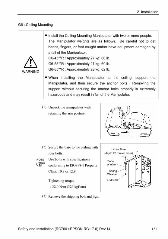
2. Installation
Safety and Installation (RC700 / EPSON RC+ 7.0) Rev.14 151
G6 : Ceiling Mounting
WARNING
Install the Ceiling Mounting Manipulator with two or more people. The Manipulator weights are as follows. Be careful not to get hands, fingers, or feet caught and/or have equipment damaged by a fall of the Manipulator. G6-45**R : Approximately 27 kg: 60 lb. G6-55**R : Approximately 27 kg: 60 lb. G6-65**R : Approximately 28 kg: 62 lb.
When installing the Manipulator to the ceiling, support the Manipulator, and then secure the anchor bolts. Removing the support without securing the anchor bolts properly is extremely hazardous and may result in fall of the Manipulator.
(1) Unpack the manipulator with
retaining the arm posture.
(2) Secure the base to the ceiling with
four bolts.
Use bolts with specifications
conforming to ISO898-1 Property
Class: 10.9 or 12.9.
Tightening torque
: 32.0 N·m (326 kgf·cm)
Screw Hole
(depth 20 mm or more)
4-M8×40
Spring Washer
Plane Washer
(3) Remove the shipping bolt and jigs.
NOTE

2. Installation
152 Safety and Installation (RC700 / EPSON RC+ 7.0) Rev.14
G10/G20 : Table Top Mounting
WARNING
Install the Table Top Mounting Manipulator with four or more people. The Manipulator weights are as follows. Be careful not to get hands, fingers, or feet caught and/or have equipment damaged by a fall of the Manipulator. G10-65** : Approximately 46 kg :102 lb. G10/G20-85** : Approximately 48 kg :106 lb. G20-A0** : Approximately 50 kg :111 lb.
(1) Secure the base to the base table with
four bolts.
Use bolts with specifications
conforming to ISO898-1 Property
Class: 10.9 or 12.9.
Tightening torque
: 73.5 N⋅m (750 kgf⋅cm)
20 mm
Screw Hole (depth 20 mm or more)
4-M12×40
Spring Washer Plane Washer
(2) Using nippers, cut off the wire tie
binding the shaft and arm retaining bracket on the base.
Bolt : M4×15
Washer : M6
Arm mounting bolt : M12×20
Wire tie
Eyebolt (Attached at shipment)
(3) Remove the bolts securing the wire ties removed in step (2).
(4) Remove the shipping bolt and jigs.
NOTE
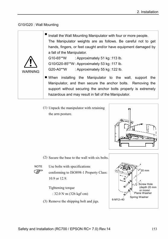
2. Installation
Safety and Installation (RC700 / EPSON RC+ 7.0) Rev.14 153
G10/G20 : Wall Mounting
WARNING
Install the Wall Mounting Manipulator with four or more people. The Manipulator weights are as follows. Be careful not to get hands, fingers, or feet caught and/or have equipment damaged by a fall of the Manipulator. G10-65**W : Approximately 51 kg :113 lb. G10/G20-85**W : Approximately 53 kg :117 lb. G20-A0**W : Approximately 55 kg :122 lb.
When installing the Manipulator to the wall, support the Manipulator, and then secure the anchor bolts. Removing the support without securing the anchor bolts properly is extremely hazardous and may result in fall of the Manipulator.
(1) Unpack the manipulator with retaining
the arm posture.
(2) Secure the base to the wall with six bolts.
Use bolts with specifications
conforming to ISO898-1 Property Class:
10.9 or 12.9.
Tightening torque
: 32.0 N·m (326 kgf·cm)
Screw Hole (depth 20 mm or more)
6-M12×40 Spring Washer
Plane Washer
20 mm
(3) Remove the shipping bolt and jigs.
NOTE

2. Installation
154 Safety and Installation (RC700 / EPSON RC+ 7.0) Rev.14
G10/G20 : Ceiling Mounting
WARNING
Install the Ceiling Mounting Manipulator with four or more people. The Manipulator weights are as follows. Be careful not to get hands, fingers, or feet caught and/or have equipment damaged by a fall of the Manipulator. G10-65**R : Approximately 46 kg :102 lb. G10/G20-85**R : Approximately 48 kg :106 lb. G20-A0**R : Approximately 50 kg :111 lb.
When installing the Manipulator to the ceiling, support the Manipulator, and then secure the anchor bolts. Removing the support without securing the anchor bolts properly is extremely hazardous and may result in fall of the Manipulator.
(1) Unpack the manipulator with retaining
the arm posture.
(2) Secure the base to the ceiling with four
bolts.
Use bolts with specifications
conforming to ISO898-1 Property Class:
10.9 or 12.9.
Tightening torque
: 32.0 N·m (326 kgf·cm)
Screw Hole (depth 20 mm or more)
4-M12×40
Spring Washer
Plane Washer
20 mm
(3) Remove the shipping bolt and jigs.
NOTE

2. Installation
Safety and Installation (RC700 / EPSON RC+ 7.0) Rev.14 155
RS
CAUTION
Install the Manipulator with two or more people. The Manipulator weights are as follows. Be careful not to get hands, fingers, or feet caught and/or have equipment damaged by a fall of the Manipulator. RS3-351*: approx. 17 kg : 38 Ib. (except cables) RS4-551*: approx. 19 kg : 42 Ib. (except cables)
When installing the Manipulator to the ceiling, support the Manipulator, and then secure the anchor bolts. Removing the support without securing the anchor bolts properly is extremely hazardous and may result in fall of the Manipulator.
(1) Unpack the Manipulator with
retaining the arm posture.
(2) Secure the base to the wall with 6
bolts.
Intensity of the bolts should be
equivalent to ISO898-1 Property
Class 10.9 or 12.9.
Tightening torque
: 13.0 N·m (133 kgf·cm)
6-M6×20
Screw hole (Depth: 12 mm
or more)
(3) Remove the shipping bolt and jigs.
NOTE

2. Installation
156 Safety and Installation (RC700 / EPSON RC+ 7.0) Rev.14
C4 There are four threaded holes for the
Manipulator base. Use M8
mounting bolts conforming to the
strength of ISO898-1 property class
12.9.
Screw Hole (depth 20mm or more)
15 mm
4-M8×35
Spring Washer
Plane Washer
C8
There are four threaded holes for the
Manipulator base.
Use M12 mounting bolts
conforming to the strength of
ISO898-1 property class 10.9 or
12.9.
Tightening torque:
100.0 ± 5.0 N·m (1,020 ± 51
kgf·cm)
16 mm
4-M12×40
Screw Hole (depth 25 mm or more)
Spring Washer
Plane Washer
Grounding
WARNING
Ground resistance must be 100 Ω or less. Improper ground resistance may result in fire and/or electric shock.
Do not use the ground line for the Manipulator in common with other ground lines or grounding electrodes for other electric power, motor power, welding devices, etc. Using the ground line for the Manipulator in common with other ground lines or grounding electrodes may result in electric shock and/or malfunction of the robot system.
When using metal ducts, metallic conduits, or distributing racks for cable, ground in accordance with national and local electric equipment technical standards. Grounding that does not meet the standards may result in electric shock and/or malfunction of the robot system.

2. Installation
Safety and Installation (RC700 / EPSON RC+ 7.0) Rev.14 157
Follow local regulations for grounding. It is recommended that the core size of
the grounding wire be 5.5 mm2 or more.
Directly connect the ground line to the Manipulator as shown in the figure below.
Detail of A 5.5 mm2 or more
Bolt hole M5 (for grounding)
N2
There are four threaded holes for the Manipulator base.
Use M6 mounting bolts conforming to the strength of ISO898-1 property class
10.9 or 12.9.
Tightening torque: 13 N·m (133 kgf·cm)
4-M6×20
Screw Hole (depth 12 mm or more)
The Joint #1 is not equipped with the brake. When installing the Manipulator, be
careful not to rotate the Joint #1.
The cable may break when exceeding Max. motion range. Be careful to operate.
NOTE

2. Installation
158 Safety and Installation (RC700 / EPSON RC+ 7.0) Rev.14
X5 If using the tap hole on the back side of the module unit and directly securing the main body:
- Process the through hole on the base table and secure from the back side. - In addition, using ø8H7 hole on the back side of the body, you can decide
where to secure. In this case, see the figure below for the pin on the base table.
Module
main unit
Base table, etc Hexagon socket head bolt
Depth of bolt
RH module RM module
Bolt diameter M8 M6 Depth of bolt 12-16 mm 9–12 mm Tightening torque 33.3N·m 14.7N·m
If using the mounting braket (option) and secure the module unit from the upper side:
- Mount the mounting braket on the module main unit with the attached bolt.
- Process a screw on te mounting base table and secure the module unit from the upper side.
RH module mounting bracket
RM module mounting bracket
YZ-MS mounting bracket
Code R114X4E001 R114X4E002 R114X4E005 Attached bolt diameter × Length (units) M8 × 20 (4) M6 × 20 (4) M8 × 20 (4)
M6 × 20 (4)
Tightening torque 33.3N·m 14.7N·m 33.3N·m (M8) 14.7N·m (M6)
(Recommended) Units to use
RH600 : 2 RH800 : 3
RH1000 : 3
RM350 : 2 RM550 : 2
RM350 : 1 RM750 : 2
Weight approx. 2.4 kg approx.1.8 kg approx.3.6 kg
Applicable module
RH RG-HM RD-HM
RP-HMSz RU-HMSz
RM RG-MS RD-MS
RP-MSSz
YZ-MS

2. Installation
Safety and Installation (RC700 / EPSON RC+ 7.0) Rev.14 159
2.5 Control unit and Drive unit Installation 2.5.1 Environment
Environment conditions
: The Control unit and Drive unit must be used within the environmental conditions described in their manuals. This product has been designed and manufactured strictly for use in a normal indoor environment. Using the product in the environment that exceeds the conditions may not only shorten the life cycle of the product but also cause serious safety problems.
For Clean-room installation
: The Control unit and Drive unit is not designed for clean-room specification. If it must be installed in a clean room, make sure to install it in the proper enclosure with adequate ventilation and cooling.
Installation procedure
: Before performing any installation procedure, turn OFF the Control unit and Drive unit and related equipment, and then pull out the power plug from the power source. Performing any replacement procedure with the power ON is extremely hazardous and may result in electric shock and/or malfunction of the robot system.
Cable
: Be sure to connect the cables properly. Do not allow unnecessary strain on the cables. (Do not put heavy objects on the cables. Do not bend or pull the cables forcibly.) The unnecessary strain on the cables may result in damage to the cables, disconnection, and/or contact failure. Damaged cables, disconnection, or a contact failure is extremely hazardous and may result in electric shock and/or improper function of the system.

2. Installation
160 Safety and Installation (RC700 / EPSON RC+ 7.0) Rev.14
In order to optimize the robot system’s performance for safety, the Controller must
be placed in an environment that satisfies the following conditions:
- The Controller is not designed for clean-room specification. If it must be installed in a clean room, be sure to install it in a proper enclosure with adequate ventilation and cooling.
- Install Controller in a location that allows easy connection / disconnection of cables.
Item Condition Ambient temperature 5 to 40 deg.C (with minimal variation) Ambient relative humidity 20% to 80% (with no condensation) First transient burst noise 2 kV or less (Power supply wire)
1 kV or les (Signal wire) Electrostatic noise 4 kV or less Base table Use a base table that is at least 100 mm off the
floor. Placing the Controller directly on the floor could allow dust penetration leading to malfunction.
If the Controller must be used in an environment that does not fulfill the conditions mentioned above, take adequate countermeasures. For example, the Controller may be enclosed in a cabinet with adequate ventilation and cooling.
- Install indoors only.
- Place in a well-ventilated area.
- Keep away from direct sunlight and radiation heat.
- Keep away from dust, oily mist, oil, salinity, metal powder or other contaminants.
- Keep away from water.
- Keep away from shocks or vibrations.
- Keep away from sources of electronic noise
- Do not apply strong electric or magnetic field.
NOTE

2. Installation
Safety and Installation (RC700 / EPSON RC+ 7.0) Rev.14 161
2.5.2 Installation Install the Control unit and Drive unit on a flat surface such as wall, floor, and controller box in the direction shown in (A) to (C).
(Figure: Control unit: RC700.)
(A) Flat mounting
(B) Upright mounting
* The rubber foot needs to be replaced. (C) Rack mounting
* A plate for rack mounting is required.
For Control unit and Drive unit installation to the Controller box or the base table, process screw hole drilling as follows.
NOTE

2. Installation
162 Safety and Installation (RC700 / EPSON RC+ 7.0) Rev.14
Ensure the air flow around the supply and exhaust ports, and install the Controller while leaving space from other equipment or walls as below.
100 mm
200 mm Excluding the installation side such as base table
Air flow of the Fan
50 mm 50 mm
200 mm
Air with higher temperature than the ambient air (about 10 deg C) is blown out from the exhaust port of the Controller. Do not place the heat sensitive devices near the exhaust port.
Route the cables so that they can be pulled out to the front side of the Controller.
2.5.3 Wall Mounting Option
The Control unit and Drive unit have a wall mounting option.
Wall mounting with the front side down
Wall mounting with the front side up
Refer to one of the following for the Installation Procedure.
Installation Procedure sheet attached to the wall mounting option.
Manual: ROBOT CONTROLLER RC700 / RC700-A Setup & Operation 3.2.3 Wall Mounting Option
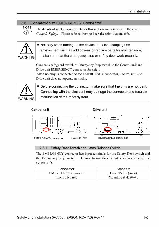
2. Installation
Safety and Installation (RC700 / EPSON RC+ 7.0) Rev.14 163
2.6 Connection to EMERGENCY Connector The details of safety requirements for this section are described in the User’s Guide 2. Safety. Please refer to them to keep the robot system safe.
WARNING
Not only when turning on the device, but also changing use environment such as add options or replace parts for maintenance, make sure that the emergency stop or safety door work properly.
Connect a safeguard switch or Emergency Stop switch to the Control unit and Drive unit EMERGENCY connector for safety. When nothing is connected to the EMERGENCY connector, Control unit and Drive unit does not operate normally.
WARNING
Before connecting the connector, make sure that the pins are not bent. Connecting with the pins bent may damage the connector and result in malfunction of the robot system.
Control unit Drive unit
EMERGENCY connecter (Figure: RC700)
EMERGENCY connecter
2.6.1 Safety Door Switch and Latch Release Switch The EMERGENCY connector has input terminals for the Safety Door switch and the Emergency Stop switch. Be sure to use these input terminals to keep the system safe.
Connector Standard EMERGENCY connector
(Controller side) D-sub25 Pin (male)
Mounting style #4-40
NOTE

2. Installation
164 Safety and Installation (RC700 / EPSON RC+ 7.0) Rev.14
2.6.2 Safety Door Switch
WARNING
The interlock of the Safety Door must be functioning when the robot system is operated. Do not operate the system under the condition that the switch cannot be turned ON/OFF (e.g. covering the switch with tape). Operating the robot system when the switch is not functioning properly is extremely hazardous and may cause serious safety problems as the Safety Door input cannot fulfill its intended function.
In order to maintain a safe working zone, a safeguard must be set up around the Manipulator. The safeguard must have an interlock switch at the entrance to the working zoon. The Safety Door that is described in this manual is one of the safeguards and an interlock of the Safety Door is called a Safety Door switch. Connect the Safety Door switch to the Safety Door input terminal on the EMERGENCY connector.
The Safety Door switch has safety features such as temporary hold-up of the program or the operation-prohibited status that are activated whenever the Safety Door is opened.
Observe the following in designing the Safety Door switch and the Safety Door.
- For the Safety Door switch, select a switch that opens as the Safety Door opens, and not by the spring of the switch itself.
- The signal from the Safety Door (Safety Door input) is designed to input to two redundant signals. If the signals at the two inputs differ by two seconds or more, the system regards it as a critical error. Therefore, make sure that the Safety Door switch has two separate redundant circuits and that each connects to the specified pins at the EMERGENCY connector on the Controller.
- The Safety Door must be designed and installed so that it does not close accidentally.
2.6.3 Latch Release Switch
The controller software latches the following conditions:
- The safety door is open. - The operation mode is “TEACH”.
The EMERGENCY connector has an input terminal for a latch release switch that cancels the latched conditions.

2. Installation
Safety and Installation (RC700 / EPSON RC+ 7.0) Rev.14 165
Open : The latch release switch latches conditions that the safety door is open or the operation mode is “TEACH”.
Closed : The latch release switch releases the latched conditions.
When the latched TEACH mode is released while the safety door is open, the status of Manipulator power is operation-prohibited because the safety door is open at that time. To execute a Manipulator operation, close the safety door again, and then close the latch release input.
2.6.4 Checking Latch Release Switch Operation
Refer to 3.2 Development PC and Controller Connection and connect the development PC and Controller before checking the function.
After connecting the safety door switch and latch release switch to the EMERGENCY connector, be sure to check the switch operation for safety by following the procedures described below before operating the Manipulator. (1) Turn ON the Controller while the safety door is open in order to boot the
controller software. (2) Make sure that “Safety” is displayed on the EPSON RC+ 7.0 status bar. (3) Close the safety door, and turn ON the switch connecting to the latch release
input. Make sure that the “Safety” is dimmed on the status bar.
The information that the safety door is open can be latched by software based on the latch release input condition.
Open : The latch release switch latches condition that the safety door is open. To cancel the condition, close the safety door, and then close the safety door latch release input.
Closed : The latch release switch does not latch the condition that the safety door is open.
The latch release input also functions to acknowledge the change of TEACH mode.
In order to change the latched condition of the TEACH mode, turn the mode selector key switch on the Teach Pendant to “Auto”. Then, close the latch release input.
NOTE
NOTE
NOTE

2. Installation
166 Safety and Installation (RC700 / EPSON RC+ 7.0) Rev.14
2.6.5 Emergency Stop Switch If it is desired to create an external Emergency Stop switch in addition to the Emergency Stop on the Teach Pendant and Operator Panel, make sure to connect the Emergency Stop switch to the Emergency Stop input terminal on the EMERGENCY connector. The Emergency Stop switch connected must comply with the related safety standards (such as IEC60947-5-5) and the following:
- It must be a push button switch that is “normally closed”.
- A button that does not automatically return or resume.
- The button must be mushroom-shaped and red.
- The button must have a double contact that is “normally closed”.
The signal from the Emergency Stop switch is designed to use two redundant circuits. If the signals at the two circuits differ by two seconds or more, the system recognizes it as a critical error. Therefore, make sure that the Emergency Stop switch has double contacts and that each circuit connects to the specified pins on the EMERGENCY connector at the Controller. Refer to the following: 2.6.8 Circuit Diagrams – Control Unit.
2.6.9 Circuit Diagrams – Drive Unit. 2.6.6 Checking Emergency Stop Switch Operation
Refer to 3.2 Development PC and Controller Connection and connect the development PC and Controller before checking the function.
Once the Emergency Stop switch is connected to the EMERGENCY connector, continue the following procedure to make sure that the switch functions properly. For the safety of the operator, the Manipulator must not be powered ON until the following test is completed.
Control Unit RC700
(1) Turn ON the Controller to boot the controller software while pressing the Emergency Stop switch.
(2) Make sure that the seven-segment LED on the Controller displays
.
(3) Make sure that “E.Stop” is displayed on the EPSON RC+ 7.0 status bar.
(4) Release the Emergency Stop Switch.
NOTE
NOTE

2. Installation
Safety and Installation (RC700 / EPSON RC+ 7.0) Rev.14 167
(5) Select EPSON RC+ 7.0-[Tools]-[Robot Manager]-[Control Panel] and click the <Reset> button to execute the RESET command.
(6) Make sure that LED is turned OFF and that “E-Stop” is dimmed on the main window status bar.
Drive Unit RC700DU
(1) Turn ON the controller to boot the software while pressing the Emergency Stop switch.
(2) Make sure that “ERROR/E-STOP” LED on Drive Unit has been turned ON.
(3) Make sure that “E.Stop” is displayed on the status bar on the EPSON RC+ main window.
(4) Release the Emergency Stop Switch.
(5) Execute the RESET command.
(6) Make sure that “ERROR/E-STOP” LED turns OFF and “E-Stop” display fades on the main window status bar.

2. Installation
168 Safety and Installation (RC700 / EPSON RC+ 7.0) Rev.14
2.6.7 Pin Assignments
The EMERGENCY connector pin assignments are as follows:
Pin No. Signal Function Pin No. Signal Function
1 ESW11 Emergency Stop switch contact (1) *3 14 ESW21 Emergency Stop switch
contact (2) *3
2 ESW12 Emergency Stop switch contact (1) *3 15 ESW22 Emergency Stop switch
contact (2) *3 3 ESTOP1+ Emergency Stop circuit 1 (+)*4 16 ESTOP2+ Emergency Stop circuit 2 (+)*4 4 ESTOP1− Emergency Stop circuit 1 (-)*4 17 ESTOP2− Emergency Stop circuit 2 (-)*4 5 Not used *1 18 SDLATCH1 Safety Door Latch Release 6 Not used *1 19 SDLATCH2 Safety Door Latch Release 7 SD11 Safety Door input (1) *2 20 SD21 Safety Door input (2) *2 8 SD12 Safety Door input (1) *2 21 SD22 Safety Door input (2) *2 9 24V +24V output 22 24V +24V output
10 24V +24V output 23 24V +24V output 11 24VGND +24V GND output 24 24VGND +24V GND output 12 24VGND +24V GND output 25 24VGND +24V GND output 13 Not used
*1 Do not connect anything to these pins. *2 A critical error occurs if the input values from the Safety Door 1 and Safety Door 2 are
different for two or more seconds. They must be connected to the same switch with two sets of contacts.
*3 A critical error occurs if the input values from the Emergency Stop switch contact 1 and Emergency Stop switch contact 2 are different for two or more seconds. They must be connected the same switch with two sets of contacts.
*4 Do not apply reverse voltage to the Emergency Stop circuit. Emergency Stop switch output rated load +30 V 0.3 A or under 1-2, 14-15 pin Emergency Stop rated input voltage range Emergency Stop rated input current
+24 V ±10% 37.5 mA ±10% / +24V input 3-4, 16-17 pin
Safety Door rated input voltage range Safety Door rated input current
+24 V ±10% 10 mA / +24 V input 7-8, 20-21 pin
Latch Release rated input voltage range Latch Release rated input current
+24 V ±10% 10 mA / +24 V input 18-19 pin
The total electrical resistance of the Emergency Stop switches and their circuit should be 1 Ω or less.
CAUTION
The 24 V output is for emergency stop. Do not use it for other purposes. Doing so may result in system malfunction.
Do not apply reverse voltage to the Emergency Stop circuit. Doing so may result in system malfunction.
NOTE

2. Installation
Safety and Installation (RC700 / EPSON RC+ 7.0) Rev.14 169
2.6.8 Circuit Diagrams – Control unit
Example 1: External emergency stop switch typical application
+24V
+5V
Safety Door input 1
External +24V
Safety Door input 2
Latch release input
Latch release input Close :Latch off Open :Latch on
Main Circuit Control
AC Input
Emergency Stop switch of an Operation Unit (TP)
External +24V GND
External Emergency Stop switches
Motor Driver + −
Controller
9
10
22
23
1
2
14
15
3
16
4
17
11
12
24
25
7
8
20
21
18
19
+
Emergency Stop detection
NOTE:+24V GND + 5V GND
Be careful of the direction of voltage application
ESTOP1+
ESTOP2+
ESTOP1−
ESTOP2-

2. Installation
170 Safety and Installation (RC700 / EPSON RC+ 7.0) Rev.14
Example 2: External safety relay typical application
* For the protection of the emergency stop circuit, the fuse’s capacity should be as follows: - Meets the capacity of
the external safety relay
- 0.4A or less
External safety relay (The above diagram is simplified for representation.)
External +24V GND
+24V
+5V
Safety Door input 1
Safety Door input 2
Latch Release input
AC Input
Motor Driver
External +24V
Fuse
+ −
External +24V
Control unit
9
10
22
23 1
2
14
15
3
16
4
17
11
12
24
25
7
8
20
21
18
19
+
Main Circuit Control
Emergency Stop switch of an Operation Unit (TP)
Emergency Stop detection
External +24V
Latch release input Close :Latch off Open :Latch on
External +24V GND NOTE:+24V GND
+ 5V GND
External +24V GND

2. Installation
Safety and Installation (RC700 / EPSON RC+ 7.0) Rev.14 171
2.6.9 Circuit Diagrams – Drive unit
Circuit Diagram
Safety Door input 1
Drive Unit
Main Circuit Control
Emergency Stop detection
Safety Door input 2
Latch release input
ESTOP2+
ESTOP1−
ESTOP2−
Be careful of the direction of voltage application
ESTOP1+

2. Installation
172 Safety and Installation (RC700 / EPSON RC+ 7.0) Rev.14
Wiring Example for Emergency Stop
Example 1: External emergency stop switch typical application
Emergency stop switch
Terminal block
Emergency stop switch of an Operation Unit (TP)
The Emergency cable, Emergency cable kit, and Terminal block are offered as
options.
Design the cables connecting the units within 20 m long.
NOTE

2. Installation
Safety and Installation (RC700 / EPSON RC+ 7.0) Rev.14 173
Example 2: External safety relay typical application
Emergency Stop switch
External +24V GND
External +24V GND
External +24V GND
External +24V
Terminal block
External +24V Fuse*
External safety relay
External +24V GND
* Fuse
For the protection of the emergency stop circuit, the fuse’s capacity should be as follows: - Meets the capacity of the external - 0.4A or less

2. Installation
174 Safety and Installation (RC700 / EPSON RC+ 7.0) Rev.14
Wiring Example for Safety Door Input / Latch Release Input
Safety Door input 1
External
Safety Door input 2
Latch release input
Latch release input Close :Latch off Open :Latch on
External
Safety Door input 1
Safety Door input 2
Latch release input
Safety Door input 1
Safety Door input 2
Latch release input
Safety Door input 1
Safety Door input 2
Latch release input
Design the cables connecting the units within 20 m long.
NOTE

2. Installation
Safety and Installation (RC700 / EPSON RC+ 7.0) Rev.14 175
2.7 Power supply, AC power cable 2.7.1 Power Supply
Ensure that the power meets the following specifications.
Item Specification Voltage 200 to 240 VAC Phase Single phase Frequency 50/60 Hz Momentary Power Interrupt 10 ms or less
Power Consumption Maximum : 2.5 kVA Actual consumption depends on the model, motion, and load of the Manipulator. For approximate power consumption of each model, refer to the followings.
C4 : 1.2 kVA C8 : 2.5 kVA N2 : 0.6 kVA G1 : 0.5 kVA G3 : 1.1 kVA G6 : 1.5 kVA G10 : 2.4 kVA G20 : 2.4 kVA RS3 : 1.2 kVA RS4 : 1.4 kVA
Refer to the Manipulator manual for rated consumption of the Manipulator motor.
Rated power consumption of X5 varies depending on the manipulator model. For details, please contact us.
Peak Current When power is turned ON : Approximately 85 A (2 ms)
When motor is ON: Approximately 75 A (2 ms)
Leakage Current Max.10 mA Ground Resistance 100 Ω or less
Install an earth leakage circuit breaker or a circuit breaker in the AC power cable line at 15 A or less rated electric current. Both should be a two-pole disconnect type. If you install an earth leakage circuit breaker, make sure to use an inverter type that does not operate by induction of a 10 kHz or more leakage current. If you install a circuit breaker, please select one that will handle the above mentioned “peak current”. The power receptacle should be installed near the equipment and should be easily accessible.
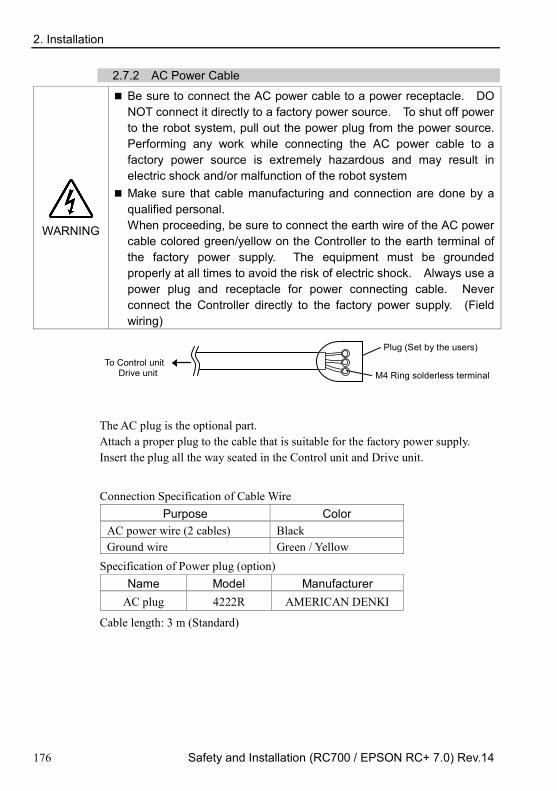
2. Installation
176 Safety and Installation (RC700 / EPSON RC+ 7.0) Rev.14
2.7.2 AC Power Cable
WARNING
Be sure to connect the AC power cable to a power receptacle. DO NOT connect it directly to a factory power source. To shut off power to the robot system, pull out the power plug from the power source. Performing any work while connecting the AC power cable to a factory power source is extremely hazardous and may result in electric shock and/or malfunction of the robot system
Make sure that cable manufacturing and connection are done by a qualified personal. When proceeding, be sure to connect the earth wire of the AC power cable colored green/yellow on the Controller to the earth terminal of the factory power supply. The equipment must be grounded properly at all times to avoid the risk of electric shock. Always use a power plug and receptacle for power connecting cable. Never connect the Controller directly to the factory power supply. (Field wiring)
Plug (Set by the users)
To Control unit Drive unit M4 Ring solderless terminal
The AC plug is the optional part. Attach a proper plug to the cable that is suitable for the factory power supply. Insert the plug all the way seated in the Control unit and Drive unit.
Connection Specification of Cable Wire
Purpose Color AC power wire (2 cables) Black Ground wire Green / Yellow
Specification of Power plug (option) Name Model Manufacturer
AC plug 4222R AMERICAN DENKI
Cable length: 3 m (Standard)

2. Installation
Safety and Installation (RC700 / EPSON RC+ 7.0) Rev.14 177
2.8 Drive Unit Connection
Drive Unit is connected to the Control Unit using the attached connection cable.
Up to three Drive Units can be connected to the Control Unit. (Figure: RC700, RC700DU)
DU IN* DU OUT* DU OUT* Drive Unit (DU): RC700DU / RC700DU-A Control Unit (CU): RC700 / RC700-A
* Name: RC700-A, RC700DU-A: OUT, IN
A: Control Unit and 1st Drive Unit (CU-DU1)
B: 1st Drive Unit and 2nd Drive Unit (DU1-DU2)
C: 2nd Drive Unit and 3rd Drive Unit (DU2-DU3)
DU2
B A
DU IN
DU1
CU
DU IN DU OUT DU OUT
DU3
C
DU IN DU OUT
When you use one Drive Unit: Connect nothing to DU OUT of the 1st Drive Unit (DU1). Otherwise, it results in the robot controller malfunction.
When you use two Drive Units: Connect nothing to DU OUT of the 2nd Drive Unit (DU2). Otherwise, it results in the robot controller malfunction.
When you use three Drive Units: Connect nothing to DU OUT of the 3rd Drive Unit (DU3). Otherwise, it results in the robot controller malfunction.
When connecting the connection cable, make sure to connect to DU IN and DU OUT properly. Improper connection may cause malfunction.
Do not use any LAN cables on the market. Otherwise, it results in the robot controller malfunction.
How to turn on the power switch: Check the connection first. Then, make sure to turn on the power switch of Drive
Unit before turning on the power switch of Control Unit.
NOTE
NOTE
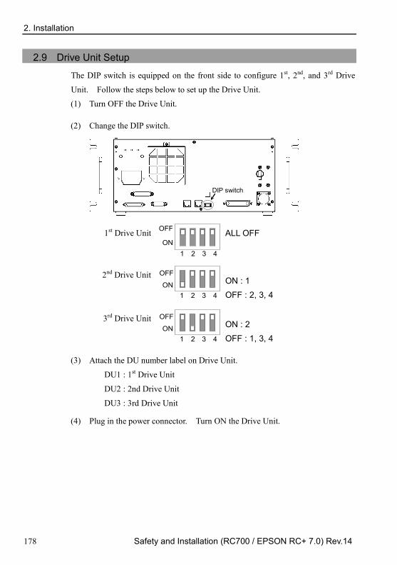
2. Installation
178 Safety and Installation (RC700 / EPSON RC+ 7.0) Rev.14
2.9 Drive Unit Setup
The DIP switch is equipped on the front side to configure 1st, 2nd, and 3rd Drive
Unit. Follow the steps below to set up the Drive Unit. (1) Turn OFF the Drive Unit.
(2) Change the DIP switch.
DIP switch
1st Drive Unit
1 2 3 4 ON
OFF
ALL OFF
2nd Drive Unit
1 2 3 4 ON
OFF
ON : 1 OFF : 2, 3, 4
3rd Drive Unit
1 2 3 4 ON
OFF
ON : 2 OFF : 1, 3, 4
(3) Attach the DU number label on Drive Unit.
DU1 : 1st Drive Unit
DU2 : 2nd Drive Unit
DU3 : 3rd Drive Unit
(4) Plug in the power connector. Turn ON the Drive Unit.

2. Installation
Safety and Installation (RC700 / EPSON RC+ 7.0) Rev.14 179
2.10 Connecting Manipulator and Controller 2.10.1 Connecting Precautions
Before Connection : Before connecting the connector, make sure that the pins are not bent.
Connecting with the pins bent may damage the connector and result in malfunction of the robot system.
Connecting procedure : Before performing any connecting procedure, turn OFF the Controller and
related equipment, and then pull out the power plug from the power source. Performing any replacement procedure with the power ON is extremely hazardous and may result in electric shock and/or malfunction of the robot system.
Cable : Be sure to connect the cables properly. Do not allow unnecessary strain on
the cables. (Do not put heavy objects on the cables. Do not bend or pull the cables forcibly.) The unnecessary strain on the cables may result in damage to the cables, disconnection, and/or contact failure. Damaged cables, disconnection, or contact failure is extremely hazardous and may result in electric shock and/or improper function of the robot system.
Connection : When connecting the Manipulator and the Controller, make sure that the serial
numbers on each equipment match. Improper connection between the Manipulator and Controller may not only cause improper function of the robot system but also safety problems. The serial number of supported Manipulator is labeled on the controller.
Wiring : Only authorized or certified personnel should be allowed to perform wiring.
Wiring by unauthorized or uncertified personnel may result in bodily injury and/or malfunction of the robot system.
For Clean-model : When the Manipulator is a Clean-model, use it with an exhaust system.
For details, refer to the Manipulator manual. For Protected-model : Connect the power cable connector and the signal cable connector to the
Manipulator immediately after the Manipulator installation. The Manipulator without connecting them may result in electric shock and/or malfunction of the robot system as it cannot ensure IP65.
Connect the power connector and the signal connector of the M/C cables to the Controller.

2. Installation
180 Safety and Installation (RC700 / EPSON RC+ 7.0) Rev.14
2.11 Power-on 2.11.1 Power-on Precautions
Manipulator check : Before operating the Manipulator, make sure that all parts of the Manipulator
are in place and have no external defects. Missing or defective parts may cause improper operation of the Manipulator. Improper operation of the Manipulator is extremely hazardous and may result in serious bodily injury and/or severe equipment damage to the robot system.
Shipping bolts and jigs check before turning ON : Before turning ON the power after installation, be sure to remove the shipping
bolts and jigs from the Manipulator. Turning ON the power while the shipping bolts and jigs are attached may result in equipment damage to the Manipulator.
Power activation : Anchor the Manipulator before turning ON the power to or operating the
Manipulator. Turning ON the power to or operating the Manipulator that is not anchored is extremely hazardous and may result in serious bodily injury and/or severe equipment damage to the robot system as the Manipulator may fall down
When supplying the power again
: When supplying the power to the controller again, turn OFF the controller and wait for 5 seconds or more. Then, turn ON the controller again.
C4, C8 series manipulator has following parts for releasing brakes. 1. Brake release unit (option) 2. External short connector
When operating the manipulator, be sure to connect either of the parts to the
position indicated below. (Figure: The external short connector is connected) C4

2. Installation
Safety and Installation (RC700 / EPSON RC+ 7.0) Rev.14 181
C8
For details on the brake release unit and the manipulators, refer to the following
manuals:
EPSON ProSix C4 series Manipulator Manual
EPSON ProSix C8 series Manipulator Manual
WARNING
If the manipulator is operated without connecting the above parts, the brakes cannot be released and it may cause damage on them.
After using the brake release unit, be sure to connect the external short connector to the Manipulator, or check connection of the connector for the brake release unit.
WARNING
When connecting or replacing the parts, turn OFF the power to the Controller and the brake release unit. Inserting and removing the connector while the power is ON may result in electrical shock.

2. Installation
182 Safety and Installation (RC700 / EPSON RC+ 7.0) Rev.14
2.11.2 Power ON Procedure
(1) Check the M/C power cable connection.
(2) Check the M/C signal cable connection.
(3) Check the EMERGENCY connector connection.
(4) Connect the TP bypass plug to the TP port of the Robot Controller.
(5) Connect the AC power cable to the power supply socket.
(6) When you use Drive Unit: Check the Control Unit and Drive Unit connection. Turn ON the Drive Unit POWER switch.
(7) Turn ON the POWER switch of the Control unit.
(8) The seven-segment LED blinks as approximately 30 seconds after Control unit starts up normally.
If an error is displayed, check connection in step (1) to (5) and turn ON the power again. If an error is displayed after checking the connection, contact the supplier in your region.
Control unit RC700/RC700-A
(8) Seven-segment LED (7) POWER switch
(Figure: RC700)
Drive unit RC700DU/RC700DU-A
(6) POWER switch
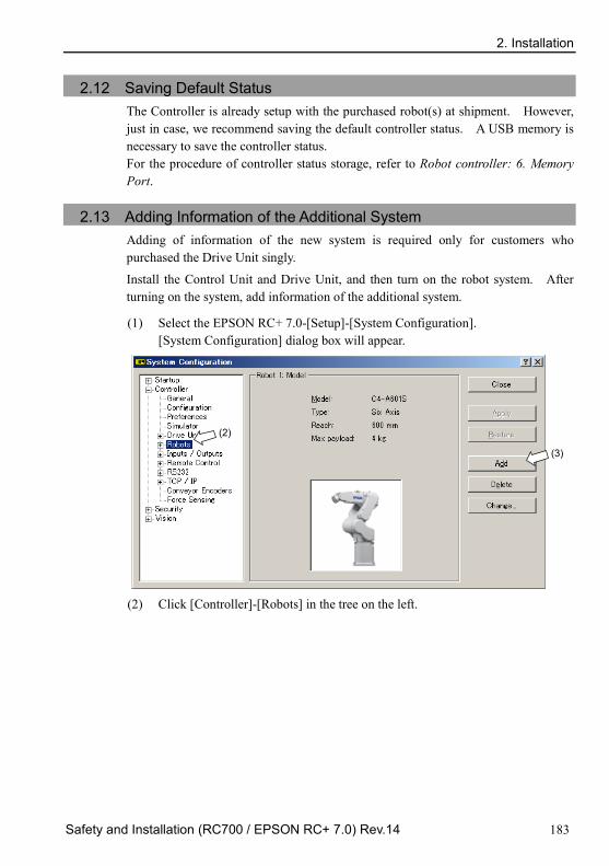
2. Installation
Safety and Installation (RC700 / EPSON RC+ 7.0) Rev.14 183
2.12 Saving Default Status The Controller is already setup with the purchased robot(s) at shipment. However, just in case, we recommend saving the default controller status. A USB memory is necessary to save the controller status. For the procedure of controller status storage, refer to Robot controller: 6. Memory Port.
2.13 Adding Information of the Additional System Adding of information of the new system is required only for customers who purchased the Drive Unit singly.
Install the Control Unit and Drive Unit, and then turn on the robot system. After turning on the system, add information of the additional system.
(1) Select the EPSON RC+ 7.0-[Setup]-[System Configuration]. [System Configuration] dialog box will appear.
(2)
(3)
(2) Click [Controller]-[Robots] in the tree on the left.

2. Installation
184 Safety and Installation (RC700 / EPSON RC+ 7.0) Rev.14
(3) Click <Add> button. [Add New Robot] dialog box will appear.
(4)
(4) Enter the following items by referring to the RC700DU Robot System Hofs
Data Sheet (hereinafter referred to as Hofs sheet) which is included with shipment.
Item Description Robot Name : Type a name for the new manipulator. (Example: RB1 Robot1) Robot Serial # : Type “Serial No.” on the Hofs sheet.
(or the serial number on the manipulator’s nameplate) Any serial number can be used, but it is recommended to use the number described above.
Motion System :
Select “Standard”. If there is no other motion systems installed, “Standard” should be already selected.
Drive Unit : Select a Drive Unit for your manipulator. (DU1, DU2, DU3) DU numbers are configured by the dip switch on the front side and indicated by the indication labels.
Robot Type : Select a manipulator type. Robot Joints : This item cannot be changed. Series : Select a manipulator series. Model : Select a manipulator model.
All manipulators available for the motor driver currently installed in the controller will be displayed.
(5) Click the <OK> button. The EPSON RC+ will restart.
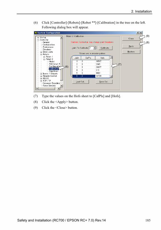
2. Installation
Safety and Installation (RC700 / EPSON RC+ 7.0) Rev.14 185
(6) Click [Controller]-[Robots]-[Robot **]-[Calibration] in the tree on the left. Following dialog box will appear.
(6) (7)
(8)
(9)
(7) Type the values on the Hofs sheet to [CalPls] and [Hofs].
(8) Click the <Apply> button.
(9) Click the <Close> button.

3. First Step
186 Safety and Installation (RC700 / EPSON RC+ 7.0) Rev.14
3. First Step This section indicates the procedure to install the development PC EPSON RC+, and execute simple program after connecting the development PC and Controller with a USB. Make sure that the Robot system is installed safely by following the description in 1. Safety and 2. Installation. Then, operate the Robot system in the following procedures.
3.1 Installing EPSON RC+ 7.0 Software
The EPSON RC+ 7.0 software needs to be installed on your development PC.
(1) Insert the EPSON RC+ 7.0 Setup DVD in the DVD drive. (2) The following dialog will be displayed. Click <Nest>.

3. First Step
Safety and Installation (RC700 / EPSON RC+ 7.0) Rev.14 187
(3) Enter your user name and company name and click <Next>.
(4) Select the drive where you want to install EPSON RC+ 7.0 and click
<Next>.
The installation directory is called EpsonRC70. This cannot be changed.
NOTE

3. First Step
188 Safety and Installation (RC700 / EPSON RC+ 7.0) Rev.14
(5) The dialog for selecting the options to be installed will be displayed. Check the options you want to install and click <Next>.
(6) The dialog to review the settings will be displayed. If you are satisfied with
the settings, click <Next>.
(7) If required, install “Windows Installer” and “Microsoft .NET Framework 3.5”
on your system. This may take several minutes. Adobe Reader needs to be installed on your PC in order to view the EPSON RC+ 7.0 manuals. If the installer cannot find Adobe Reader on your system, it will be installed at this time. Follow the instructions in the Adobe installer. Do not restart the system after the Adobe Reader installation has completed.
(8) After the installation has completed, restart your computer. The EPSON RC+ 7.0 software installation is now completed.
NOTE

3. First Step
Safety and Installation (RC700 / EPSON RC+ 7.0) Rev.14 189
3.2 Development PC and Controller Connection Connect the development PC and the USB port for connection (USB B series connector).
Development PC connection Port (Figure: RC700)
- For other details of development PC and Controller connection, refer to EPSON RC+7.0 User’s Guide: PC to Controller Communications Command.
- For RC700 / RC700-A, be sure to install the EPSON RC+7.0 to the development PC first, then connect the development PC and RC700 / RC700-A with the USB cable. If RC700 / RC700-A and the development PC are connected without installing the EPSON RC+7.0 to the development PC, [Add New Hardware Wizard] appears. If this wizard appears, click the <Cancel> button.
3.2.1 About Development PC Connection USB Port
Development PC connection port supports following USB. - USB2.0 HighSpeed/FullSpeed (Speed auto selection, or FullSpeed mode) - USB1.1 FullSpeed Interface Standard : USB specification Ver.2.0 compliant (USB Ver.1.1 upward compatible)
Connect the Controller and development PC by a USB cable to develop the robot system or set the Controller configuration with the EPSON RC+ 7.0 software installed in the development PC.
Development PC connection port supports hot plugging. Insertion and removal of the cables while the power of the development PC and the Controller are ON is available. However, the manipulator stops when the USB cable is removed while the Controller and the development PC are connected.
NOTE

3. First Step
190 Safety and Installation (RC700 / EPSON RC+ 7.0) Rev.14
3.2.2 Precaution
When connecting the development PC and the Controller, make sure of the following.
- Connect the development PC and the Controller with 5 m or shorter USB cable. Do not use the USB hub or extension cable.
- Make sure that no other devices except development PC is used for development PC connection port.
- Use PC or USB cable that supports USB2.0 HighSpeed mode to operate in USB2.0 HighSpeed mode.
- Do not pull or bend the cable strongly. - Do not allow unnecessary strain on the cable. - When development PC and the Controller is connected, do not insert or
remove other USB devices from the development PC. Connection with the Controller may disconnect.
3.2.3 Software Setup and Connection Check
The following is the steps of connecting the development PC and the Controller.
(1) Make sure that EPSON RC+ 7.0 is installed on the Controller connected to the development PC. (Install the software when it is not installed.)
(2) Connect the development PC and the Controller by the USB cable.
(3) Turn ON the Controller.
(4) Start the software EPSON RC+ 7.0.
(5) Select the EPSON RC+ 7.0 menu-[Setup]-[PC to Controller Communications] to display the [PC to Controller Communications] dialog.

3. First Step
Safety and Installation (RC700 / EPSON RC+ 7.0) Rev.14 191
(6) Select the “No.1 USB” and click the <Connect> button.
(7) After development PC and the Controller connection is completed, “Connected” is displayed in the [Connection status:]. Make sure that “Connected” is displayed and click the <Close> button to close the [PC to Controller Communications] dialog.
Connection of the development PC and the Controller is completed. Now robot system can be used from EPSON RC+ 7.0.
3.2.4 Backup the initial condition of the Controller
Backup the Controller data configured before shipment.
Project and system configuration backup procedure:
(1) From the [Project] menu, select [Copy]. (2) Change the [Destination Drive] to an arbitrary drive. (3) Click <OK>. The project will be copied to the external media. (4) From the [Tools] menu, select [Controller]. (5) Click on the <Backup Controller> button. (6) Select the arbitrary drive. (7) Click <OK>. The system configuration will be backed up on the external
media.

3. First Step
192 Safety and Installation (RC700 / EPSON RC+ 7.0) Rev.14
3.2.5 Disconnection of Development PC and Controller
Disconnection of the development PC and the Controller is indicated.
(1) Select the EPSON RC+ 7.0 menu-[Setup]-[PC to Controller Communications] to display the [PC to Controller Communications] dialog.
(2) Click the <Disconnect> button. Controller and the development PC is disconnected and USB cable can be removed.
If the USB cable is removed while the Controller and the development PC are connected, the Manipulator stops. Be sure to click the <Disconnect> button in the [PC to Controller Communications] dialog before removing the USB cable.
3.2.6 Moving the Robot to Initial Position
Robot can be operated by the following methods other than creating and executing the program.
Manual operation
Jog motion by the Teach Pendant
Command execution from the EPSON RC+
Jog motion from the EPSON RC+
This section explains about following methods.
A: Manual operation
B: Command execution from the EPSON RC+
C: Jog motion from the EPSON RC+
NOTE

3. First Step
Safety and Installation (RC700 / EPSON RC+ 7.0) Rev.14 193
A: Manual operation Move the non-excited robot manually.
For SCARA robot: Joints with no electromagnetic brake can be moved manually. Joints with the brakes (Joint #3 only, or Joints #3 and #4) can be moved manually while the break release switch on the manipulator is being pressed with the controller ON.
For 6-axis robot: Manipulators can be moved manually by pressing the brake release switch when the brake release unit is connected. For details, refer to Brake Release Unit in each manipulator manual.
Also, manipulators can be moved manually by releasing the electromagnetic brake from the command window of the EPSON RC+.
CAUTION
Normally, release the brake of joints one by one. Take extra care if you need to release the brakes of two or more joints simultaneously. Releasing the brakes of two or more joints simultaneously may result in hands or fingers being caught and/or equipment damage to or malfunction of the Manipulator as the arms of the Manipulator may move in unexpected directions.
Be careful of the arm falling when releasing the brake. While the brake is being released, the Manipulator’s arm falls by its own weight. The arm falling may result in hands or fingers being caught and/or equipment damage to or malfunction of the Manipulator.
Before releasing the brake, be sure to keep the Emergency Stop switch handy so that you can immediately press the Emergency Stop switch. Otherwise, you cannot immediately stop the arm falling due to an erroneous operation. The arm falling may cause equipment damage to and/or malfunction of the Manipulator.
3. First Step
194 Safety and Installation (RC700 / EPSON RC+ 7.0) Rev.14
(1) Start the EPSON RC+ 7.0. Double click the <EPSON RC+ 7.0> icon on the desktop.
(2) Open the command window. EPSON RC+ 7.0 menu-[Tool]-[Command Window]
(3) Execute the following command in [Command Window]. >Reset
>Brake Off,[Arm # (1 to 6) whose brake will be released]
Execute the following command to turn on the brake again. >Brake On,[Arm # (1 to 6) whose brake will be turned on]
B: Command execution from the EPSON RC+ Move the robot by exciting the robot motors and executing the command.
Following explains the example of moving all joints to the 0 pulse positions by specifying the pulse for each joint.
(1) Start the EPSON RC+ 7.0.
Double click the <EPSON RC+ 7.0> icon on the desktop. (2) Open the command window.
EPSON RC+ 7.0 menu-[Tools]-[Command Window] (3) Execute the following command in [Command Window].
For SCARA robot: >Motor On
>Go Pulse (0,0,0,0)
For 6-axis robot: >Motor On
>Go Pulse (0,0,0,0,0,0)
For position and posture of Manipulator at 0 pulse position, refer to Motion Range in the Manipulator manuals.

3. First Step
Safety and Installation (RC700 / EPSON RC+ 7.0) Rev.14 195
C: Jog motion from the EPSON RC+ Move the robot by exciting the motors and operating from the Jog & Teach window of the EPSON RC+.
(1) Start the EPSON RC+ 7.0.
Double click the <EPSON RC+ 7.0> icon on the desktop. (2) Create a new project.
1. EPSON RC+ 7.0 menu-[Project]-[New Project]. [New Project] dialog
box will be displayed.
2. Enter the project name in [Project Name] box. (Ex: FirstApp)
3. Click the <OK> button and create the new project. (3) Open the robot manager.
EPSON RC+ 7.0 menu-[Tools]-[Robot Manager].

3. First Step
196 Safety and Installation (RC700 / EPSON RC+ 7.0) Rev.14
(4) Turn ON the motors. Check that the [Control Panel] tab is open. Click the <MOTOR ON> button.
(5) Move the manipulator with Jog motion. 1. Select [Jog & Teach] tab.
2. Select “Joint” in [Jogging]-<Mode>. 3. Move the manipulator by joint by clicking J1-J6 jog keys.
Manipulator can be moved by setting to other modes or setting the jog distance.
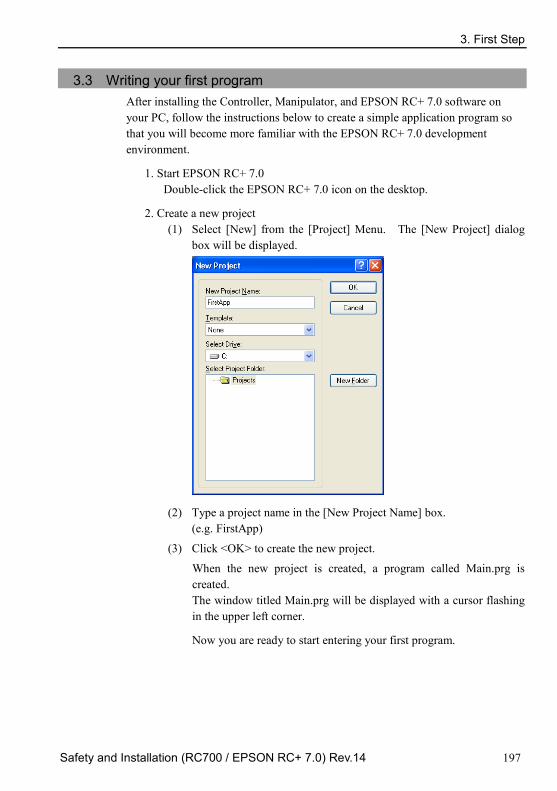
3. First Step
Safety and Installation (RC700 / EPSON RC+ 7.0) Rev.14 197
3.3 Writing your first program After installing the Controller, Manipulator, and EPSON RC+ 7.0 software on your PC, follow the instructions below to create a simple application program so that you will become more familiar with the EPSON RC+ 7.0 development environment.
1. Start EPSON RC+ 7.0 Double-click the EPSON RC+ 7.0 icon on the desktop.
2. Create a new project (1) Select [New] from the [Project] Menu. The [New Project] dialog
box will be displayed.
(2) Type a project name in the [New Project Name] box. (e.g. FirstApp)
(3) Click <OK> to create the new project.
When the new project is created, a program called Main.prg is created. The window titled Main.prg will be displayed with a cursor flashing in the upper left corner.
Now you are ready to start entering your first program.

3. First Step
198 Safety and Installation (RC700 / EPSON RC+ 7.0) Rev.14
3. Edit the program Type the following program lines in the Main.prg edit window.
Function main Print "This is my first program." Fend

3. First Step
Safety and Installation (RC700 / EPSON RC+ 7.0) Rev.14 199
4. Run the program (1) Press F5 to run the program. (F5 is the hot key for the [Run Window]
selection of the [Run] Menu). You will see the Status window located at the bottom of the main window showing the build operation status.
(2) During project build, your program is compiled and linked. Then communications is established with the controller and project files are sent to the controller. If there are no errors during build, the Run window will appear.
(3) Click the Start button on the Run window to run the program.
(4) The texts like the following will be displayed in the status window. 19:32:45 Task main started
19:32:45 All tasks stopped
On the Run window, you will see the output of the print statement.
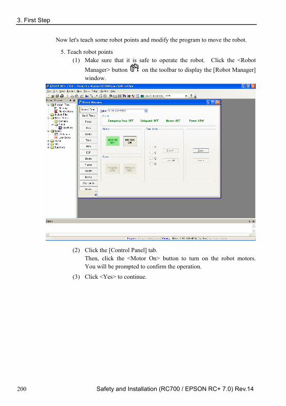
3. First Step
200 Safety and Installation (RC700 / EPSON RC+ 7.0) Rev.14
Now let's teach some robot points and modify the program to move the robot.
5. Teach robot points (1) Make sure that it is safe to operate the robot. Click the <Robot
Manager> button on the toolbar to display the [Robot Manager] window.
(2) Click the [Control Panel] tab. Then, click the <Motor On> button to turn on the robot motors. You will be prompted to confirm the operation.
(3) Click <Yes> to continue.

3. First Step
Safety and Installation (RC700 / EPSON RC+ 7.0) Rev.14 201
(4) Click the [Jog & Teach] tab.
(5) Click the <Teach> button in the lower right corner to teach point P0. You will be prompted for a point label and description.
(6) Click the <+Y> jog button to jog the robot in +Y direction. Hold the button down to keep jogging. Move the robot until it reaches the middle of the work envelope.
(7) Click the <-Z> button to lower the Z axis of the robot.
(8) Select “P1” in the [Point (P)] dropdown list which is next to the <Teach> button. The current point is set to P1.
(9) Click the <Teach> button. You will see a confirmation message to teach the point.
(10) Click the <Yes> button.
(11) Click the <+X> button to jog the robot in the +X direction.
(12) Select “P2” in the [Point (P)] dropdown list which is next to the <Teach> button. The current point is set to P2.
(13) Click the <Teach> button. You will see a confirmation message to teach the point.
(14) Click the <Yes> button.
(15) Click the <Save Project> toolbar button to save the changes.

3. First Step
202 Safety and Installation (RC700 / EPSON RC+ 7.0) Rev.14
6. Modify the program to include robot motion commands (1) Insert three new Go statements into the Main.prg program as shown
below: Function main
Print "This is my first program."
Go P1
Go P2
Go P0
Fend (2) Press F5 to display the Run window.
(3) Click the <Start> button to execute the program. The robot will move to the points you taught.
7. Modify the program to change speed of robot motion commands (1) Insert the Power, Speed, and Accel commands as shown in the
program below: Function main
Print "This is my first program."
Power High
Speed 20
Accel 20, 20
Go P1
Go P2
Go P0
Fend (2) Press F5 to display the Run window.
(3) Click the <Start> button to execute the program.
The robot will move to each of the points you taught at 20% speed, acceleration, and deceleration. The Power High statement executes the program to operate the robot with increased speed and acceleration.

3. First Step
Safety and Installation (RC700 / EPSON RC+ 7.0) Rev.14 203
8. Backup the project and system configuration Even though this is only a sample project, we will backup the project and controller configuration. Backup can be done easily with EPSON RC+ 7.0. It is important that you keep regular backups of your applications on an external media such as a USB memory key.
Follow the steps below to back up the project and system configuration:
(1) Select the EPSON RC+ 7.0 menu - [Project] - [Copy].
(2) Change the [Destination Drive] to an arbitrary drive.
(3) Click <OK>. The project will be copied to the external media.
(4) Select the EPSON RC+ 7.0 menu - [Tools] - [Controller].
(5) Click on the <Backup Controller> button.
(6) Select the arbitrary drive.
(7) Click <OK>. The system configuration will be backed up on the
external media.

4. Second Step
204 Safety and Installation (RC700 / EPSON RC+ 7.0) Rev.14
4. Second Step After operating the robot system as instructed in 3. First Step, setup other functions as necessary. This section shows the manuals which contains information of necessary settings and setting procedure. (For details of the manuals, refer to 6. Manuals.)
4.1 Connection with External Equipment
4.1.1 Remote Control
EPSON RC+ 7.0 User’s Guide Remote Control
ROBOT CONTROLLER RC700/RC700-A manual Setup & Operation: I/O Remote Set Up
I/O EPSON RC+ 7.0 User’s Guide
I/O Setup ROBOT CONTROLLER RC700/RC700-A manual
Setup & Operation: 11. I/O Connector Setup & Operation: 14.2 Expansion I/O Board
Fieldbus I/O (Option) ROBOT CONTROLLER RC700/RC90 Option Fieldbus I/O Board 4.1.2 Ethernet
EPSON RC+ 7.0 User’s Guide Ethernet Communication
ROBOT CONTROLLER RC700/RC700-A manual Setup & Operation: 7. LAN (Ethernet Communication) Port
4.1.3 RS-232C (Option)
EPSON RC+ 7.0 User’s Guide RS-232C Communication
ROBOT CONTROLLER RC700/RC700-A manual Setup & Operation: 14.4 RS-232C Board
4.1.4 Analog I/O board (Option)
ROBOT CONTROLLER RC700/RC700-A manual Setup & Operation: 14.6 Analog I/O board
4.1.5 Force Sensor I/F board (Option)
ROBOT CONTROLLER RC700/RC700-A manual Setup & Operation: 14.7 Force Sensor I/F board

4. Second Step
Safety and Installation (RC700 / EPSON RC+ 7.0) Rev.14 205
4.2 Ethernet Connection of Development PC and Controller EPSON RC+ 7.0 User’s Guide
Ethernet Communication ROBOT CONTROLLER RC700/RC700-A manual
Setup & Operation: 7. LAN (Ethernet Communication) Port
4.3 Connection of Teach Pendant (Option)
Robot Controller RC700/RC700-A manual Setup & Operation: TP Port
RC700/RC90 Option Teach Pendant TP1 manual Functions & Installation: Installation
RC700/RC90 Option Teach Pendant TP2 manual Functions & Installation: Installation
RC700-A Option Teach Pendant TP3 manual Functions & Installation: Installation

5. General Maintenance
206 Safety and Installation (RC700 / EPSON RC+ 7.0) Rev.14
5. General Maintenance This chapter describes maintenance inspections and procedures. Performing maintenance inspections and procedures properly is essential for preventing trouble and ensuring safety. Be sure to perform the maintenance inspections in accordance with the schedule.
5.1 Maintenance
5.1.1 Manipulator Inspection points are divided into five stages: daily, monthly, quarterly, biannual, and annual. The inspection points are added every stage. If the Manipulator is operated for 250 hours or longer per month, the inspection points must be added every 250 hours, 750 hours, 1500 hours, and 3000 hours operation.
Inspection Point
Daily Monthly Quarterly Biannual Annual Overhaul (replacement)
1 month (250 h)
Inspect every day
√
2 months (500 h) √
3 months (750 h) √ √
4 months (1000 h) √
5 months (1250 h) √
6 months (1500 h) √ √ √
7 months (1750 h) √
8 months (2000 h) √
9 months (2250 h) √ √
10 months (2500 h) √
11 months (2750 h) √
12 months (3000 h) √ √ √ √
13 months (3250 h) √
…
…
…
…
…
…
20,000 h √ h = hour

5. General Maintenance
Safety and Installation (RC700 / EPSON RC+ 7.0) Rev.14 207
Inspection While the Power is ON (Manipulator is operating) Inspection Point Inspection
Place Daily Monthly Quarterly Biannual Annual
Check motion range Each joint √ Move the cables back and forth lightly to check whether the cables are disconnected.
External cables (including cable unit of the Manipulator)
√ √
Push each arm in MOTOR ON status to check whether backlash exists.
Each arm √
Check whether unusual sound or vibration occurs. Whole √ √ √ √ √
Measure the accuracy repeatedly by a gauge. Whole √
RS, G1, G3, G6, G10, G20 Turn ON and OFF the Brake Release switch and check the sound of the electromagnetic brake. If there is no sound, replace the brake.
Brake √ √ √ √ √
C4, C8, N2 When brake release unit is installed:
Connect the brake release unit and check the sound of the electromagnetic brake with the brake released. If there is no sound, replace the brake.
When brake release unit is not installed:
Execute Brake off command (brake off, joint #) from the command window of the EPSON RC+ while the motors are OFF, and then check the sound of the electromagnetic brake. If there is no sound, replace the brake.
Brake √ √ √ √ √

5. General Maintenance
208 Safety and Installation (RC700 / EPSON RC+ 7.0) Rev.14
X5
Inspection items Recommended Intervals
Loose bolts, connectors and cables Once a week
Inspect timing belt for damage and looseness. Every half year
Replace cables. Every two years
Replace timing belt. Every two years

5. General Maintenance
Safety and Installation (RC700 / EPSON RC+ 7.0) Rev.14 209
Inspection While the Power is OFF (Manipulator is not operating) Inspection Point Inspection Place Daily Monthly Quarterly Biannual Annual
Check looseness or backlash of bolts/screws. Tighten them if necessary. (For the tightening torque, refer to Tightening Hexagon Socket Head Cap Bolts.)
End effector mounting bolts √ √ √ √ √
Manipulator mounting bolts √ √ √ √ √
Each arm locking bolts √ √ √ √ √
Bolts/screws around shaft √
Bolts/screws securing motors, reduction gear units, etc.
√
Check looseness of connectors. If the connectors are loosen, push it securely or tighten.
External connectors on Manipulator (on the connector plates etc.)
√ √ √ √ √
Manipulator cable unit √ √ √ √
Visually check for external defects. Clean up if necessary.
External appearance of Manipulator
√ √ √ √ √
External cables √ √ √ √ Check for bends or improper location. Repair or place it properly if necessary.
Safeguard etc. √ √ √ √ √
Check tension of timing belts. Tighten it if necessary.
Base, Inside of Arm √ √
Grease conditions Refer to 5.4 Greasing. Battery Refer to 5.5 Handling and Disposal of Batteries C4, C8, N2: Check either the external short connector or the brake release unit connector is connected.
The external short connector on the back side of the Manipulator, or the brake release unit connector.
√ √ √ √ √

5. General Maintenance
210 Safety and Installation (RC700 / EPSON RC+ 7.0) Rev.14
X5 Inspection Point Inspection Place Daily Monthly Quarterly Biannual Annual
Replace a cable or flexible tube if it has serious crack or breakage. Check for loose bolts by tightening them.
Cables √ √ √ √ √
Check for a loose bolts by tightening them.
Bolts for securing the module √ √ √ √ √
Bolts for securing the end effector √ √ √ √ √

5. General Maintenance
Safety and Installation (RC700 / EPSON RC+ 7.0) Rev.14 211
5.1.2 Control Unit (RC700, RC700-A)
Part Fan filter Fan (Front) Fan (Rear) Battery Content Cleaning Replacement Replacement Replacement Replacement
Code - R13N865021 R13B060510 R13B060510 R13B060003 Quantity - 1 1 1 1
Maintenance interval
More than once a month is recommended
When the filter gets deteriorated
When the error 515 occurs, or when the abnormal noise occurs
When the error 516 occurs, or when the abnormal noise occurs
Every 5 years, or when the error 511 occurs
Possible malfunction if maintenance is not performed
The temperature inside the Controller may get too high and the robot system may not operate properly. The error may occur due to reduction of the fun rotation.
The robot system may not operate properly due to dust or the like.
The error 9015 occurs and the robot system may stop.
The error 9016 occurs and the robot system may stop.
The error 9011 occurs and the robot system may stop.
Duration (reference) 5 minutes 5 minutes 20 minutes 15 minutes 5 minutes
Reference: Maintenance
7.1 Fan Filter
7.1 Fan Filter
7.2.1 Front Fan
7.2.2 Regenerative Fan (RC700-A only)
7.3 Battery
Expected product life - - 30,000 hours 30,000 hours -
* Refer to the Maintenance chapters in the Robot Controller RC700/RC700-A manual.

5. General Maintenance
212 Safety and Installation (RC700 / EPSON RC+ 7.0) Rev.14
5.1.3 Drive Unit (RC700DU, RC700DU-A)
Part Fan filter Fan (Front) Fan (Rear) Content Cleaning Replacement Replacement Replacement
Code - R13N865021 R13B060510 R13B060510 Quantity - 1 1 1
Maintenance interval
More than once a month is recommended
When the filter gets deteriorated
When the error * 525, 535, 545 occurs, or when the abnormal noise occurs
When the error * 526, 536, 546 occurs, or when the abnormal noise occurs
Possible malfunction if maintenance is not performed
The temperature inside the Controller may get too high and the robot system may not operate properly. The error may occur due to reduction of the fun rotation.
The robot system may not operate properly due to dust or the like.
One of the errors * 9025, 9035, or 9045 occurs and the robot system may stop.
One of the errors * 9026, 9036, or 9046 occurs and the robot system may stop.
Duration (reference) 5 minutes 5 minutes 20 minutes 15 minutes
Reference: Maintenance
4.1 Fan Filter
4.1 Fan Filter
4.2.1 Front Fan
4.2.2 Regenerative Fan (RC700DU-A only)
Expected product life - - 30,000 hours 30,000 hours
* The error number depends on the number of Drive Units.
* Refer to the Maintenance chapters in the Robot Controller RC700DU/RC700DU-A manual.

5. General Maintenance
Safety and Installation (RC700 / EPSON RC+ 7.0) Rev.14 213
5.2 Overhaul (Parts Replacement)
CAUTION
Overhaul timing is based on an assumption that all joints are operated for equal distance. If a particular joint has a high duty or high load, it is recommended to overhaul all joints (as many as possible) before exceeding 20,000 operation hours with the joint as a basis.
The parts for the manipulator joints may cause accuracy decline or malfunction due to deterioration of the manipulator resulting from long term use. In order to use the manipulator for a long term, it is recommended to overhaul the parts (parts replacement).
The time between overhauls is 20,000 operation hours of the Manipulator as a rough indication.
However, it may vary depending on usage condition and degree of the load (such as when operated with the maximum motion speed and maximum acceleration / deceleration in continuous operation) applied on the Manipulator.
For the EPSON RC+ 7.0 Ver. 7.2.x or later (firmware Ver.7.2.x.x or later), the recommended replacement time for the parts subject to maintenance (motors, reduction gear units, and timing belts) can be checked in the [Maintenance] dialog box of the EPSON RC+ 7.0. For details, refer to the following manual. Robot Controller RC700 / RC700-A Maintenance 6. Alarm
Note: The recommended replacement time for the maintenance parts is when it reaches the L10 life (time until 10% failure probability). In the [Maintenance] dialog box, the L10 life is displayed as 100%.
The manipulator operation hours can be checked in [Controller Status Viewer] dialog -[Motor On Hours].
(1) Select EPSON RC+ menu-[Tools]-[Controller] to open the [Controller Tools] dialog.
(2) Click the <View Controller Status> button to open the [Browse For Folder] dialog.
(3) Select the folder where the information is stored.
(4) Click <OK> to view the [Controller Status Viewer] dialog.
NOTE

5. General Maintenance
214 Safety and Installation (RC700 / EPSON RC+ 7.0) Rev.14
(5) Select [Robot] from the tree menu on the left side (Dialog image: EPSON RC+ 7.0)
For the parts subject to overhaul, refer to Manipulator manual: Maintenance section: Maintenance Parts List.
For details of replacement of each part, refer to the Manipulator manual: Maintenance section.
Please contact the distributor of your region for further information.
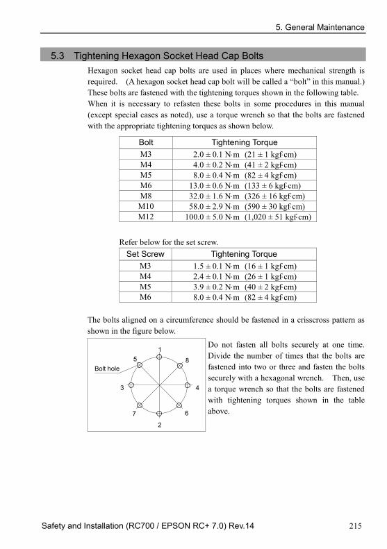
5. General Maintenance
Safety and Installation (RC700 / EPSON RC+ 7.0) Rev.14 215
5.3 Tightening Hexagon Socket Head Cap Bolts Hexagon socket head cap bolts are used in places where mechanical strength is required. (A hexagon socket head cap bolt will be called a “bolt” in this manual.) These bolts are fastened with the tightening torques shown in the following table. When it is necessary to refasten these bolts in some procedures in this manual (except special cases as noted), use a torque wrench so that the bolts are fastened with the appropriate tightening torques as shown below.
Bolt Tightening Torque M3 2.0 ± 0.1 N⋅m (21 ± 1 kgf⋅cm) M4 4.0 ± 0.2 N⋅m (41 ± 2 kgf⋅cm) M5 8.0 ± 0.4 N⋅m (82 ± 4 kgf⋅cm) M6 13.0 ± 0.6 N⋅m (133 ± 6 kgf⋅cm) M8 32.0 ± 1.6 N⋅m (326 ± 16 kgf⋅cm)
M10 58.0 ± 2.9 N⋅m (590 ± 30 kgf⋅cm) M12 100.0 ± 5.0 N⋅m (1,020 ± 51 kgf⋅cm)
Refer below for the set screw.
Set Screw Tightening Torque M3 1.5 ± 0.1 N⋅m (16 ± 1 kgf⋅cm) M4 2.4 ± 0.1 N⋅m (26 ± 1 kgf⋅cm) M5 3.9 ± 0.2 N⋅m (40 ± 2 kgf⋅cm) M6 8.0 ± 0.4 N⋅m (82 ± 4 kgf⋅cm)
The bolts aligned on a circumference should be fastened in a crisscross pattern as shown in the figure below.
1 5
3
7
2
6
4
8 Bolt hole
Do not fasten all bolts securely at one time. Divide the number of times that the bolts are fastened into two or three and fasten the bolts securely with a hexagonal wrench. Then, use a torque wrench so that the bolts are fastened with tightening torques shown in the table above.

5. General Maintenance
216 Safety and Installation (RC700 / EPSON RC+ 7.0) Rev.14
5.4 Greasing The ball screw spline and reduction gear units need greasing regularly. Only use the grease specified.
This section contains information of the parts requiring lubrication and greasing intervals. For details of the lubrication procedure, refer to the Manipulator manual.
CAUTION
Keep enough grease in the Manipulator. Operating the Manipulator with insufficient grease damages the sliding parts resulting in insufficient Manipulator performance. It may also require a lot of time and money for repair.
If grease gets into your eyes, mouth, or on your skin, follow the instructions below. If grease gets into your eyes:
Flush them thoroughly with clean water, and then see a doctor immediately.
If grease gets into your mouth: If swallowed, do not induce vomiting. See a doctor immediately. If grease just gets into your mouth, wash out your mouth with water thoroughly.
If grease gets on your skin Wash the area thoroughly with soap and water.

5. General Maintenance
Safety and Installation (RC700 / EPSON RC+ 7.0) Rev.14 217
For the EPSON RC+ 7.0 Ver. 7.2.x or later (firmware Ver.7.2.x.x or later), the recommended replacement time for the grease can be checked in the [Maintenance] dialog box of the EPSON RC+ 7.0.
For details, refer to the following manual. Robot Controller RC700 / RC700-A Maintenance 6. Alarm
G, RS series Greasing part Greasing Interval
Joint #1, #2 Reduction gear units Overhaul timing
Joint #3 Ball screw spline shaft At 100 km of operation (50 km for first greasing)
Joint #1, 2 reduction gear units As a rough indication, perform greasing at the same timing as overhaul. However, it may vary depending on usage condition and degree of the load (such as when operated with the maximum motion speed and maximum acceleration / deceleration in continuous operation) applied on the Manipulator.
Joint #3 Ball screw spline shaft The recommended greasing interval is at 100 km of operation. However, perform greasing at 50 km of operation for the first time of greasing.
C4, C8 series Greasing part Greasing Interval
All Joints Reduction gear units Overhaul timing Joint #6 Bevel gear Once a year (every 8000 hours)
Joint #1, 2, 3, 4, 5, 6 reduction gear units As a rough indication, perform greasing at the same timing as overhaul. However, it may vary depending on usage condition and degree of the load (such as when operated with the maximum motion speed and maximum acceleration / deceleration in continuous operation) applied on the Manipulator.
N2 Greasing part Greasing Interval
All Joints Actuator unit, Reduction gear unit
Overhaul timing
Joint #1, 2, 3, 4, 5, 6 actuator units, Joint #5 reduction gear unit As a rough indication, perform greasing at the same timing as overhaul. However, it may vary depending on usage condition and degree of the load (such as when operated with the maximum motion speed and maximum acceleration / deceleration in continuous operation) applied on the Manipulator.
NOTE

5. General Maintenance
218 Safety and Installation (RC700 / EPSON RC+ 7.0) Rev.14
X5 Ball screws and linear guides used for the modules are equipped with a unique lubrication system, which consists of the K1 lubrication unit* and high load grease. Because of this lubrication system, you do not need replenish the grease if the robot system is going to be operated in the conditions described hereunder.
(1) Clean environment and no contamination. (2) Ambient temperature is 0°C to 40°C and no condensation. (3) Load conditions, transportable mass and moment are in the criteria as
specified. * K1 lubrication unit: Made of a porous synthetic resin that contains a large amount of lubricating oil and supplies the lubrication oil for a long time.

5. General Maintenance
Safety and Installation (RC700 / EPSON RC+ 7.0) Rev.14 219
5.5 Handling and Disposal of Batteries
CAUTION
Use meticulous care when handling the lithium battery. Improper handling of the lithium battery as mentioned below is extremely hazardous, and may result in heat generation, leakage, explosion, or inflammation, and may cause serious safety problems.
・Battery Charge ・Disassembly ・Incorrect Installation ・Exposing to Fire ・Forced Discharge
・Deformation by Pressure ・Short-circuit (Polarity; Positive/Negative) ・Heating (85°C or more) ・Soldering the terminal of the lithium battery directly
Be sure to use the battery supplied as maintenance part from EPSON.
When disposing the battery, consult with the professional disposal services or comply with the local regulation. Spent battery or not, make sure the battery terminals are insulated. If the terminal contacts with the other metals, it may short and result in heat generation, leakage, explosion, or inflammation.
WARNING
Do not insert or pull out the motor connectors while the power to the robot system is turned ON. Inserting or pulling out the motor connectors with the power ON is extremely hazardous and may result in serious bodily injury as the Manipulator may move abnormally, and also may result in electric shock and/or malfunction of the robot system.
To shut off power to the robot system, pull out the power plug from the power source. Be sure to connect the AC power cable to a power receptacle. DO NOT connect it directly to a factory power source.
Before performing any replacement procedure, turn OFF the Controller and related equipment, and then pull out the power plug from the power source. Performing any replacement procedure with the power ON is extremely hazardous and may result in electric shock and/or malfunction of the robot system.

5. General Maintenance
220 Safety and Installation (RC700 / EPSON RC+ 7.0) Rev.14
Robot Controller Before starting battery replacement, turn on the controller for approximately one minute. Perform the replacement within 10 minutes to prevent data loss. Make sure to use the designated lithium battery.
Manipulator When the lithium battery power is low, an error will occur to warn the user about the low battery status when the Controller is turned ON (when software is started up). When the error occurs, the position data in motors will be lost and all joints need to be completely calibrated again. The life span of the lithium battery varies depending on the energizing hours and installation environment of the Controller. The general life spans of the batteries are as follows (when the Controller is connected to power for 8 hours a day). When the Controller is not connected to power, the battery consumption will significantly increase compared to when the Controller is energized. If warnings of voltage reduction occur, replace the lithium metal battery even if it has not reached the above product life.
Manipulator Battery life C4 series 1.5 years RS, G1, G3, G6, G10, G20, C8, N2, X5 series 3 years
For the EPSON RC+ 7.0 Ver. 7.2.x or later (firmware Ver.7.2.x.x or later), the recommended replacement time for the battery can be checked in the [Maintenance] dialog box of the EPSON RC+ 7.0. For details, refer to the following manual. Robot Controller RC700 / RC700-A Maintenance 6. Alarm
The battery may run out if it passes the recommended replacement time. If the error of the Power-low warning is not occurred, the calibration of the all joints is not necessary. However, when the position is out of place after the battery replacement, perform the calibration. Be sure to use the designated lithium battery and the battery board. Be sure to set the correct polar when installing the battery.
NOTE

6. Manuals
Safety and Installation (RC700 / EPSON RC+ 7.0) Rev.14 221
6. Manuals This section describes contents of each manual. The manuals below are provided in PDF format for using the robot system. To read the PDF manuals on a PC, select EPSON RC+ 7.0-[Help]-[PDF Manual]. (Click <Start>-[Program]-[EPSON RC+ 7.0] from the Windows desktop.)
Software
EPSON RC+ 7.0 User’s Guide This manual contains information on the Robot system and program development software.
- Safety
- Robot System Operation and Configuration
- Operation of Program Development Software EPSON RC + GUI
- SPEL+ Language and Application
- Configuration of Robot, I/O, Communication
EPSON RC+ 7.0 SPEL+ Language Reference This manual contains information on the SPEL+ programming language.
- Details of the commands
- Error Messages
- Precaution of EPSON RC+ 4.0, 5.0, and 6.0 Compatibility
Software Options Followings manuals contain information on the software options and commands.
- RC+ API 7.0 - Vision Guide 7.0 Hardware & Setup - Vision Guide 7.0 Software
- Vision Guide 7.0 Properties & Results Reference
- GUI Builder 7.0
- Remote Control Reference - Force Control 7.0
- Force Control 7.0 Properties & Status Reference

6. Manuals
222 Safety and Installation (RC700 / EPSON RC+ 7.0) Rev.14
Controller
ROBOT CONTROLLER RC700/RC700-A
DRIVE UNIT RC700DU/RC700DU-A This manual indicates descriptions of the Robot Controller RC700, RC700-A, Drive unit RC700DU, RC700DU-A and Robot system.
- Safety
- Specification, Installation, Operation, and Setup
- Backup and Restore
- Maintenance
- Verifying Robot System Operation
- Error Codes
Controller Options
Followings manuals contain information on the controller options. - PG Motion System - Fieldbus I/O - Teach Pendant TP1 - Teach Pendant TP2 - Teach Pendant TP3
Manipulator
The manipulator manuals contain information on the manipulator(s).
Each manipulator model has a different manual.
EPSON SCARA ROBOT : G1, G3, G6, G10, G20, RS (RS3, RS4)
EPSON ProSix : C4, C8, N2
EZ module : X5 series
- Safety
- Specification, Installation, Setting
- Maintenance
- Calibration

7. Directives and Norms
Safety and Installation (RC700 / EPSON RC+ 7.0) Rev.14 223
7. Directives and Norms These products conform to the following directives and norms. For more details of the controller and the manipulator, please refer to each manual.
Product Name Model
Controller RC700 RC700-A Manipulator C4 series C8 series G series RS series N series X5 series
Name Definition
Directive 2006/42/EC Directive 2006/42/EC of the European Parliament and of the Council of 17 May 2006 on machinery, and amending Directive 95/16/EC
Directive 2004/108/EC Directive 2004/108/EC relating to electromagnetic compatibility and repealing Directive 89/336/EEC
EN ISO 12100 (2010) Safety of machinery -- General principles for design -- Risk assessment and risk reduction
EN ISO 10218-1 (2011) Robots and robotic devices -- Safety requirements for industrial robots -- Part 1: Robots
EN 60204-1 (/A1:2009) Safety of machinery -- Electrical equipment of machines -- Part 1: General requirements
EN ISO 13849-1 (2008) *
Safety of machinery -- Safety - related parts of control systems -- Part 1: General principles for design
EN ISO 13850 (2008) Safety of machinery -- Emergency stop - principles for design EN 55011 (2009) Industrial, scientific and medical (ISM) radio-frequency
equipment -- Electromagnetic disturbance characteristics -- Limits and methods of measurement
EN 61000-6-2 (2005) Electromagnetic compatibility (EMC) -- Part 6-2: Generic standards -- Immunity for industrial environments
*Emergency stop circuit category3, PL d
Safety Door circuit category3, PL d