Embed Size (px)
Citation preview
SAFETY ANALYSIS REPORT
NEF Safety Analysis Report Revision 2, July 2004 Page 3.3-i
TABLE OF CONTENTS
Page
3.3 FACILITY DESCRIPTION ......................................................................................3.3-1 3.3.1 Buildings and Major Components...............................................................3.3-1
3.3.1.1 Separations Building Modules.....................................................3.3-1 3.3.1.2 Technical Services Building ........................................................3.3-3 3.3.1.3 Cylinder Receipt and Dispatch Building ......................................3.3-9 3.3.1.4 Centrifuge Assembly Building....................................................3.3-11 3.3.1.5 Blending and Liquid Sampling Area ..........................................3.3-14 3.3.1.6 Uranium Byproduct Cylinder (UBC) Storage Pad......................3.3-15 3.3.1.7 Central Utilities Building ............................................................3.3-16 3.3.1.8 Administration Building..............................................................3.3-17 3.3.1.9 Visitor Center.............................................................................3.3-18 3.3.1.10 Site Security Buildings...............................................................3.3-18
3.3.2 Structural Design Criteria..........................................................................3.3-19 3.3.2.1 Codes and Standards................................................................3.3-20 3.3.2.2 Structural Design Loads ............................................................3.3-20 3.3.2.3 Foundations...............................................................................3.3-34
3.3.3 References ...............................................................................................3.3-34
NEF Safety Analysis Report Revision 2, July 2004 Page 3.3-ii
LIST OF TABLES
Table 3.3-1 Distances To Site Boundary and To Restricted Area Boundary and Wind Frequencies
NEF Safety Analysis Report Revision 1, February 2004 Page 3.3-iii
LIST OF FIGURES
Figure 3.3-1 Facility Buildings and Areas Figure 3.3-2 Separations Building Module First Floor Figure 3.3-3 UF6 Handling Area Equipment Location Figure 3.3-4 Separations Building Module Second Floor Figure 3.3-5 Separations Building Module Third Floor Figure 3.3-6 Separations Building Module Sections Figure 3.3-7 Technical Services Building First Floor Figure 3.3-8 Technical Services Building Second Floor Figure 3.3-9 Technical Services Building Sections Figure 3.3-10 Cylinder Receipt and Dispatch Building First Floor Part A Figure 3.3-11 Cylinder Receipt and Dispatch Building First Floor Part B Figure 3.3-12 Cylinder Receipt and Dispatch Building Sections Figure 3.3-13 Centrifuge Assembly Building First Floor Figure 3.3-14 Centrifuge Assembly Building Second Floor Figure 3.3-15 Centrifuge Assembly Building Penthouse Figure 3.3-16 Centrifuge Assembly Building Sections Figure 3.3-17 Blending and Liquid Sampling Area First Floor Figure 3.3-18 Central Utilities Building First Floor
NEF Safety Analysis Report Revision 2, July 2004 Page 3.3-1
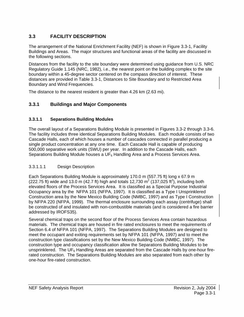
3.3 FACILITY DESCRIPTION
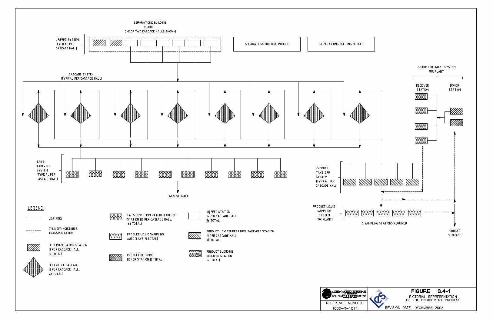
The arrangement of the National Enrichment Facility (NEF) is shown in Figure 3.3-1, Facility Buildings and Areas. The major structures and functional areas of the facility are discussed in the following sections.
Distances from the facility to the site boundary were determined using guidance from U.S. NRC Regulatory Guide 1.145 (NRC, 1982), i.e., the nearest point on the building complex to the site boundary within a 45-degree sector centered on the compass direction of interest. These distances are provided in Table 3.3-1, Distances to Site Boundary and to Restricted Area Boundary and Wind Frequencies.
The distance to the nearest resident is greater than 4.26 km (2.63 mi).
3.3.1 Buildings and Major Components
3.3.1.1 Separations Building Modules
The overall layout of a Separations Building Module is presented in Figures 3.3-2 through 3.3-6. The facility includes three identical Separations Building Modules. Each module consists of two Cascade Halls, each of which houses a number of cascades connected in parallel producing a single product concentration at any one time. Each Cascade Hall is capable of producing 500,000 separative work units (SWU) per year. In addition to the Cascade Halls, each Separations Building Module houses a UF6 Handling Area and a Process Services Area.
3.3.1.1.1 Design Description
Each Separations Building Module is approximately 170.0 m (557.75 ft) long x 67.9 m (222.75 ft) wide and 13.0 m (42.7 ft) high and totals 12,730 m2 (137,025 ft2), including both elevated floors of the Process Services Area. It is classified as a Special Purpose Industrial Occupancy area by the NFPA 101 (NFPA, 1997). It is classified as a Type I Unsprinklered Construction area by the New Mexico Building Code (NMBC, 1997) and as Type I Construction by NFPA 220 (NFPA, 1999). The thermal enclosure surrounding each assay (centrifuge) shall be constructed of and insulated with non-combustible materials (and is considered a fire barrier addressed by IROFS35).
Several chemical traps on the second floor of the Process Services Area contain hazardous materials. The chemical traps are housed in fire rated enclosures to meet the requirements of Section 6.4 of NFPA 101 (NFPA, 1997). The Separations Building Modules are designed to meet the occupant and exiting requirements set by NFPA 101 (NFPA, 1997) and to meet the construction type classifications set by the New Mexico Building Code (NMBC, 1997). The construction type and occupancy classification allow the Separations Building Modules to be unsprinklered. The UF6 Handling Areas are separated from the Cascade Halls by one-hour fire-rated construction. The Separations Building Modules are also separated from each other by one-hour fire-rated construction.
NEF Safety Analysis Report Revision 2, July 2004 Page 3.3-2
3.3.1.1.2 Functional Areas and Major Components
3.3.1.1.2.1 Cascade Halls
Each Cascade Hall contains eight cascades. The centrifuges are mounted on precast concrete floor mounting elements (flomels). Each Cascade Hall is enclosed by a structural steel frame, which is supporting insulated sandwich panels. This cascade enclosure surrounds each Cascade Hall to aid in maintaining a constant temperature within the cascade enclosure. This enclosure will also be constructed to have a minimum one hour fire-resistive rating.
3.3.1.1.2.2 Process Services Area
The Process Services Area contains the gas transport equipment, which connects the cascades to the UF6 Feed System, the Product Take-off System, the Tails Take-off System and the Contingency Dump System.
The first floor of the Process Services Area, at elevation 1,040 m (3,415 ft) mean sea level (msl), contains various pieces of equipment, control cabinets and electrical cabinets. The second floor of the Process Services Area, at elevation 1,045 m (3,431.5 ft) msl, contains various pieces of equipment, control cabinets, electrical cabinets, valve support frames, process pumps and chemical traps. The third floor of the Process Services Area at elevation 1,049 m (3,444.5 ft) msl, contains various pieces of equipment, control cabinets, electrical cabinets, water pumps and heating and ventilation equipment. The various floors of the Process Services Area can be accessed by one of three stairways or by the elevator.
A. UF6 Handling Area
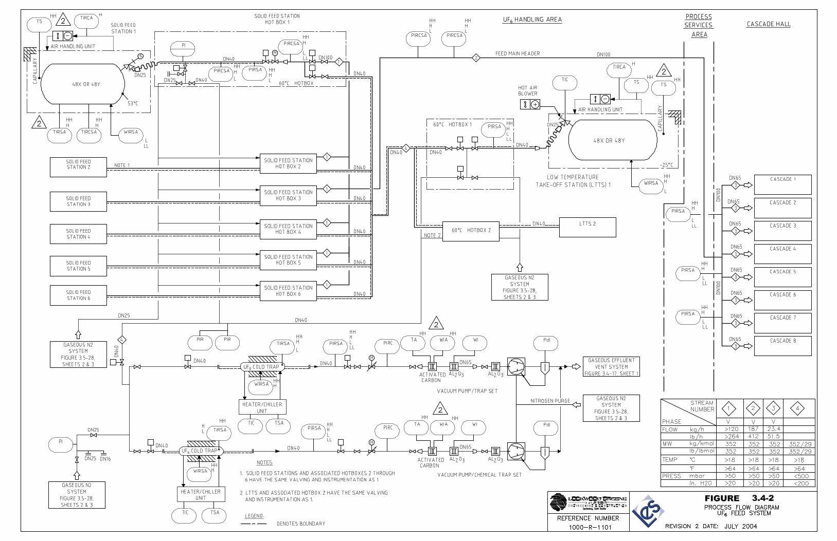
The UF6 Handling Area contains the UF6 Feed System, the Product Take-off System, and the Tails Take-off System. The UF6 Handling Area is approximately 43.3 m (142 ft) x 67.9 m (222.75 ft) and totals 2940 m2 (31,646 ft2).
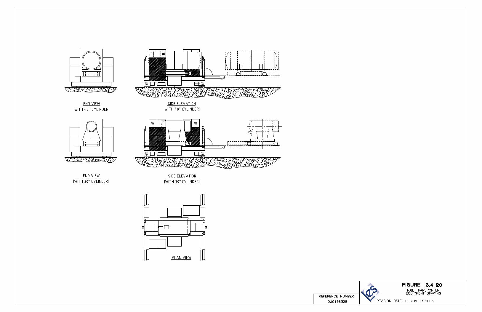
Rail transporters travel on rails embedded in the floor along the entire length of the facility. The rail transporter moves the cylinders to and from the appropriate feed or receiver stations. It has the ability to handle both the 48-inch feed cylinders and UBCs and 30-inch or 48-inch product cylinders.
3.3.1.1.2.3 Building Construction
Each Separations Building Module superstructure is structurally independent from the rest of the facility and is designed to be missile resistant. The superstructure is of precast/prestressed concrete construction using rectangular columns, rectangular and inverted tee beams, double or single tee roof and floor members and solid wall panels.
The roof structure over the Separations Building Module consists of deep precast/prestressed concrete double or single tee members covered with a thin layer of isocyanurate insulation board, which provides a barrier between the concrete surface and the single-ply roof membrane. The single ply membrane is then covered by 100 mm (4 in) of dow board insulation, filter fabric and concrete pavers. The tee members are supported by concrete ‘L’ girders around the perimeter and inverted tee girders on interior spans. These will, in turn, be supported by
NEF Safety Analysis Report Revision 2, July 2004 Page 3.3-3
concrete columns supported on concrete spread footings. The roof assembly has a minimum combined thermal resistance value of R-20.
Exterior walls are precast insulated concrete panels. These walls will act as shear walls to provide lateral support for the structure. The exterior wall assembly has a minimum combined thermal resistance value of R-10. The interior side of the exterior wall is smooth concrete, which has been sealed and painted.
Interior non-load bearing walls are constructed of 200 mm (8 in) concrete block with an epoxy painted finish. These walls extend to the underside of the structure where required.
The floors of the Cascade Halls have a floor profile quality classification of flat in accordance with ACI 117-90 (ACI, 1990a) to aid in the transport of assembled centrifuges.
Floors in the Cascade Halls and UF6 Handling Areas are of exposed concrete with a washable epoxy coating finish. The coatings are designed to resist process chemicals, decontamination agents and radiation.
3.3.1.2 Technical Services Building
The overall layout of the Technical Services Building (TSB) is presented in Figures 3.3-7 through 3.3-9. The TSB is located between column lines 1 and 11 and column lines N.1 and W, adjacent to the Blending and Liquid Sampling Area. The TSB contains support areas for the facility. It also acts as the secure point of entry to the Separations Building Modules and the Cylinder Receipt and Dispatch Building (CRDB).
3.3.1.2.1 Design Description
The TSB is a two-story structure, 10.0 m (32.8 ft) in height and totals 9,192 m2 (98,942 ft2). It is classified as a Special Purpose Industrial Occupancy area by NFPA 101 (NFPA, 1997). The TSB is classified as a Type I Unsprinklered Construction area by the New Mexico Building Code (NMBC, 1997) and as Type I Construction by NFPA 220 (NFPA, 1999). The TSB is designed to meet the occupant and exiting requirements set by the NFPA 101 (NFPA, 1997) and to meet the construction type classifications set by the New Mexico Building Code (NMBC, 1997). Several areas of the TSB have hazardous materials in quantities less than exempt amounts and are separated from areas by one-hour fire-rated construction. These areas include:
• Solid Waste Collection Room • Vacuum Pump Rebuild Workshop • Decontamination Workshop • Ventilated Room.
Several of the TSB areas are separated from adjacent areas by one-hour fire-rated construction. These areas include: • Liquid Effluent Collection and Treatment Room • TSB GEVS Room • Sample Storage Room which is located in the Chemical Lab.
NEF Safety Analysis Report December 2003 Page 3.3-4
3.3.1.2.2 Functional Areas and Major Components
3.3.1.2.2.1 Solid Waste Collection Room
The Solid Waste Collection Room is designed to process both wet and dry low-level radioactive solid waste. The Solid Waste Collection System is described in Section 3.5.13, Solid Waste Collection. Wet waste is categorized as radioactive, hazardous or industrial waste and includes assorted materials, oil recovery sludge, oil filters and miscellaneous hazardous wastes. Dry waste is also categorized as radioactive, hazardous or industrial waste and includes assorted materials, activated carbon, activated aluminum oxide, activated sodium fluoride, high efficiency particulate air (HEPA) filters, scrap metal and miscellaneous hazardous materials.
This room is approximately 15.0 m (49.25 ft) x 20.0 m (65.6 ft) x 5.0 m (16.4 ft) high and totals 300 m2 (3,229 ft2). It is classified as a Special Purpose Industrial Occupancy area with a less than exempt amount of hazardous materials. This area is separated from the other Special Purpose Industrial Occupancy areas by one-hour fire-rated construction.
3.3.1.2.2.2 Vacuum Pump Rebuild Workshop
The Vacuum Pump Rebuild Workshop is designed to provide space for the maintenance and re-building of plant equipment, mainly pumps which have been decontaminated in the Decontamination Workshop, and other miscellaneous plant equipment.
This room is approximately 12.8 m (42 ft) x 20.0 m (65.6 ft) x 5.0 m (16.4 ft) high and contains 256 m2 (2,756 ft2). The workshop consists of an open area, a storage area and a data logging/progress chasing area. It is equipped with suitable area lighting, a degassing oven, heating, ventilating, and air conditioning (HVAC), local extract systems, vacuum systems and a spray booth with a filter and extraction system. It is classified as a Special Purpose Industrial Occupancy area with a less than exempt amount of hazardous materials. This area is separated from the other Special Purpose Industrial Occupancy areas by one-hour fire-rated construction.
3.3.1.2.2.3 Decontamination Workshop
The purpose of the Decontamination Workshop is to provide a maintenance facility for both UF6 pumps and vacuum pumps. It is also used for the temporary storage and subsequent dismantling of failed pumps. The activities carried out within the Decontamination Workshop include receipt and storage of contaminated pumps, out-gassing, Fomblin oil removal and storage, pump stripping, and the dismantling and maintenance of valves and other plant components.
The Decontamination Workshop also provides a facility for the removal of radioactive contamination from contaminated materials and equipment. The Decontamination System consists of a series of steps including equipment disassembly, degreasing, decontamination, drying and inspection. Components commonly decontaminated include pumps, valves, piping, instruments, sample bottles, tools and scrap metal. The Decontamination System is described in Section 3.5.14, Decontamination Workshop.
NEF Safety Analysis Report December 2003 Page 3.3-5
The Decontamination Workshop is maintained at a lower pressure than surrounding areas. Therefore any equipment or personnel entering this room must go through an air-lock.
This room is approximately 22.1 m (72.5 ft”) x 20.0 m (65.6 ft) x 5.0 m (16.4 ft) high and contains 442 m2 (4,758 ft2). It is classified as a Special Purpose Industrial Occupancy area with a less than exempt amount of hazardous materials. This area is separated from the other Special Purpose Industrial Occupancy areas by one-hour fire-rated construction.
3.3.1.2.2.4 Ventilated Room
The Ventilated Room is designed to provide space for the maintenance of chemical traps and cylinders. The Ventilated Room is also used for the temporary storage of full and empty chemical traps and the contaminated chemicals used in the chemical traps.
The activities carried out within the Ventilated Room include receipt and storage of saturated chemical traps, chemical removal and temporary storage, contaminated cylinder pressure testing, and UF6 cylinder pump out and valve maintenance.
The Ventilated Room is maintained at a lower pressure than surrounding areas. Therefore, any equipment or personnel entering this room must go through an air-lock.
This room is approximately 14.9 m (48.9 ft) x 20.0 m (65.6 ft) x 5.0 m (16.4 ft) high and contains 298 m2 (3,208 ft2). It is classified as a Special Purpose Industrial Occupancy area with a less than exempt amount of hazardous materials. This area is separated from the other Special Purpose Industrial Occupancy areas by one-hour fire-rated construction.
3.3.1.2.2.5 Cylinder Preparation Room
The Cylinder Preparation Room is designed for the purpose of testing and inspecting new or cleaned 30B, 48X, and 48Y cylinders for use in the facility.
This room is approximately 25.0 m (82 ft) x 20.0 m (65.6 ft) x 10 m (32.8 ft) high and totals 500 m2 (5,382 ft2). It is classified as a Special Purpose Industrial Occupancy area.
The Cylinder Preparation Room is maintained at a lower pressure than surrounding areas. Therefore any equipment or personnel entering this room must go through an air-lock.
3.3.1.2.2.6 Mechanical, Electrical and Instrumentation (ME&I) Workshop
The ME&I Workshop is designed to provide space for the normal maintenance of non-contaminated plant equipment. The facility also deals with faults associated with the pump motors, all instrument and control equipment, lighting, power, and associated process and services pipe work. It also provides space for the temporary storage of rebuilt equipment and other minor plant equipment.
This room is approximately 14.8 m (48.6 ft) x 20.0 m (65.6 ft) x 10.0 m (32.8 ft) high and totals 296 m2 (3,186 ft2). It is classified as a Special Purpose Industrial Occupancy area.

NEF Safety Analysis Report Revision 2, July 2004 Page 3.3-6
3.3.1.2.2.7 Liquid Effluent Collection and Treatment Room
The Liquid Effluent Collection and Treatment Room is designed for the collection of potentially contaminated liquid effluents produced on site, which are monitored for contamination prior to processing. These liquid effluents are stored in tanks prior to processing. The effluents are segregated into significantly contaminated effluent, slightly contaminated effluent or non-contaminated effluent. Liquid effluents produced by the facility include hydrolysed uranium hexafluoride and aqueous laboratory effluent, degreaser water, citric acid, laundry effluent water, floor washings, miscellaneous condensates and active area hand washings/shower water. The Liquid Waste Collection System is described in Section 3.5.12, Liquid Effluent Collection and Treatment System.
This room is approximately 19.8 m (64.9 ft) x 20.0 m (65.6 ft) x 10.0 m (32.8 ft) high and totals 396 m2 (4,263 ft2). It is classified as a Special Purpose Industrial Occupancy area. The Liquid Effluent Collection and Treatment Room is separated from adjacent areas by one-hour fire-rated construction.
3.3.1.2.2.8 Laundry
The Laundry is designed to clean contaminated and soiled clothing and other articles, which have been used throughout the facility. Laundry is sorted into two categories, articles with a high possibility of contamination and articles unlikely to have been contaminated. Those that are likely to be contaminated are further sorted into lightly and heavily soiled articles. Heavily soiled articles are transferred to the solid waste disposal system without having been washed.
The Laundry contains two industrial quality washing machines (75 kg (165 lb) capacity), two industrial quality dryers (75 kg (165 lb) capacity), one sorting hood to draw potentially contaminated air away, a sorting table and an inspection table. The Laundry System is described in Section 3.5.16, Laundry System. The Laundry also contains a small office and storage room.
This room is approximately 161.2 m2 (1,735 ft2). It is classified as a Special Purpose Industrial Occupancy area.
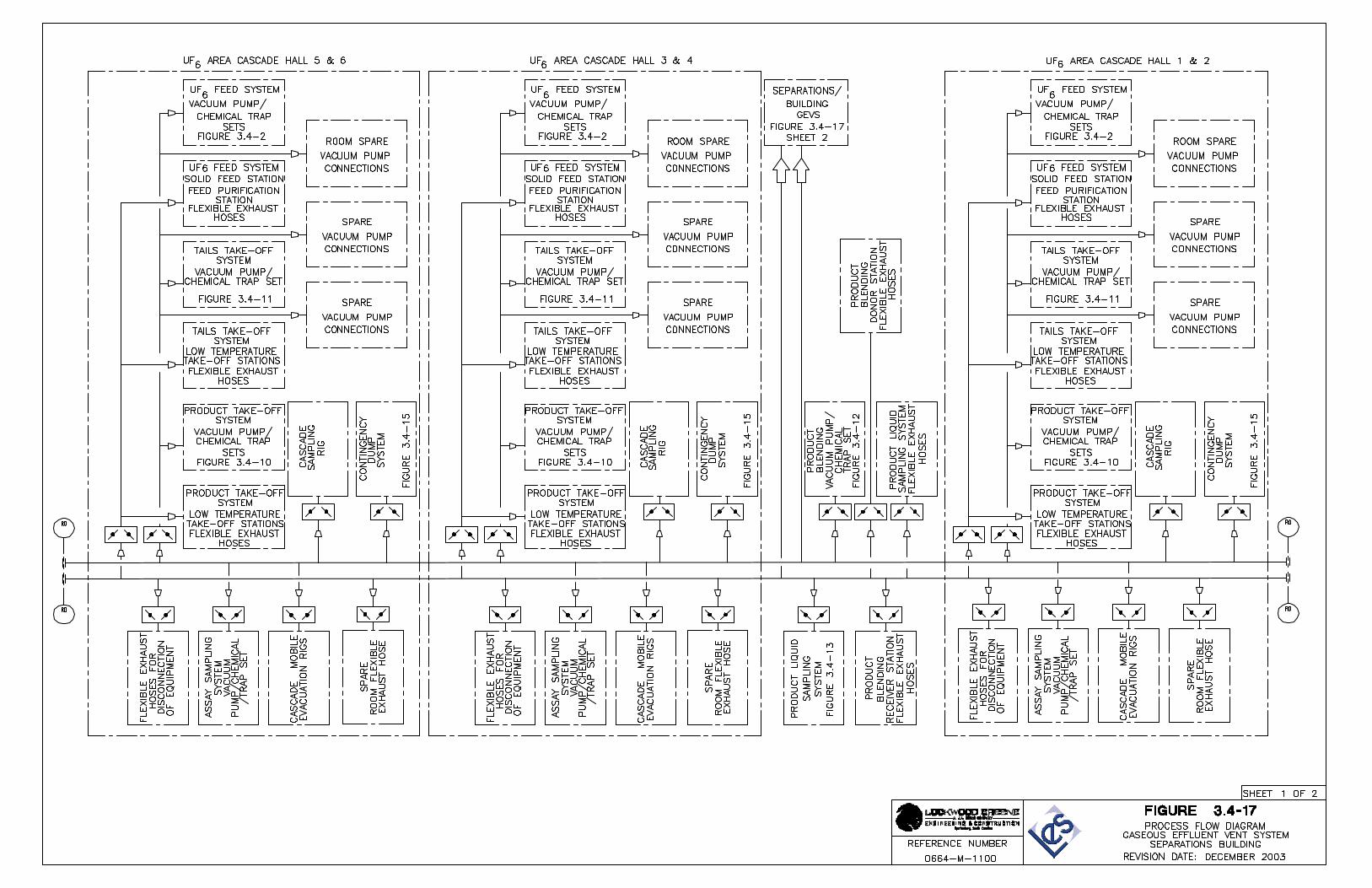
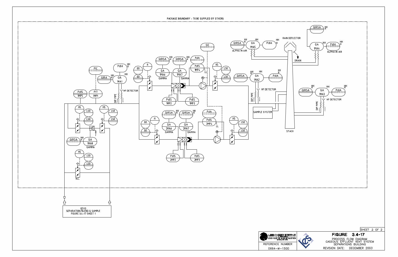
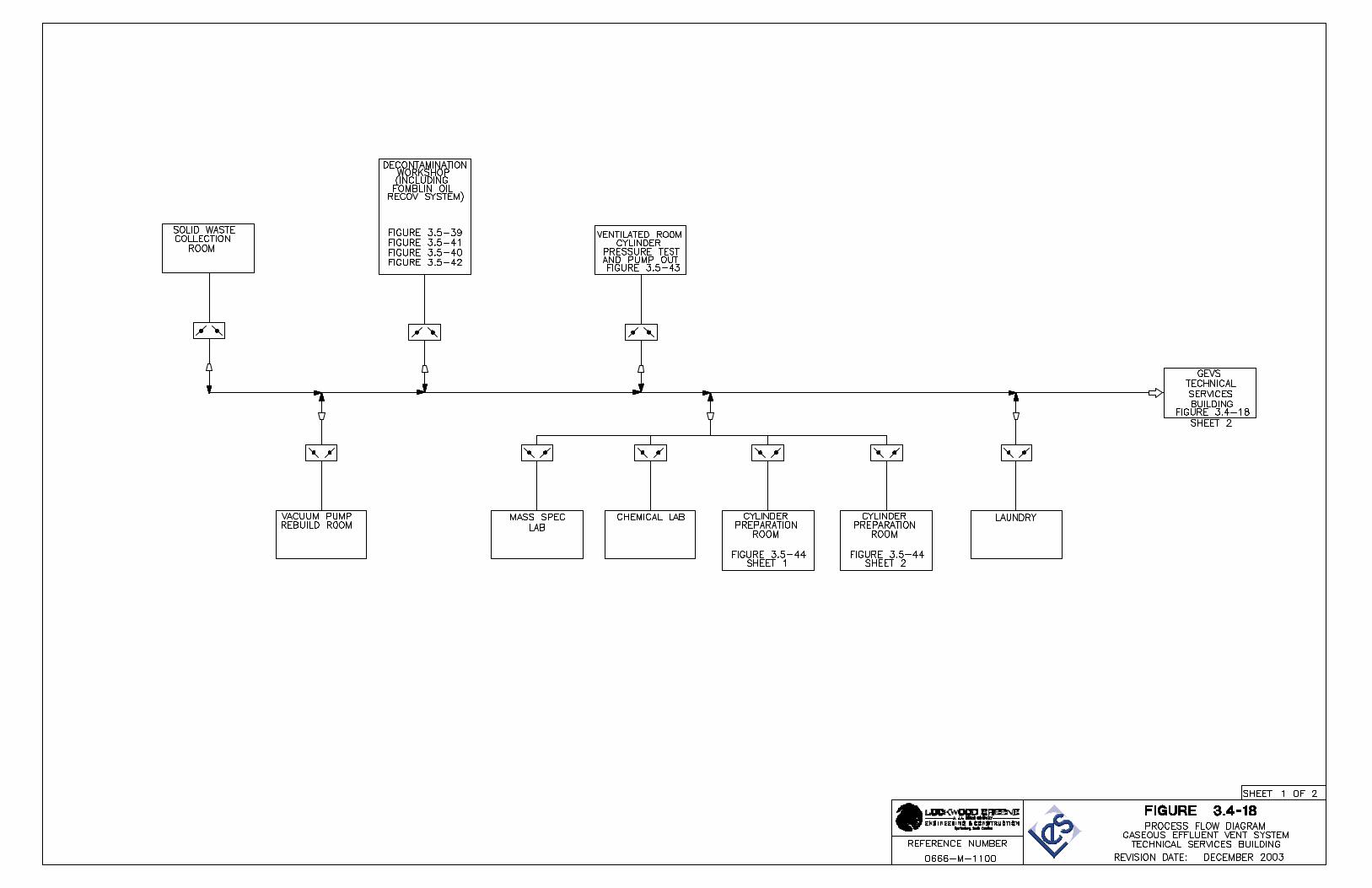
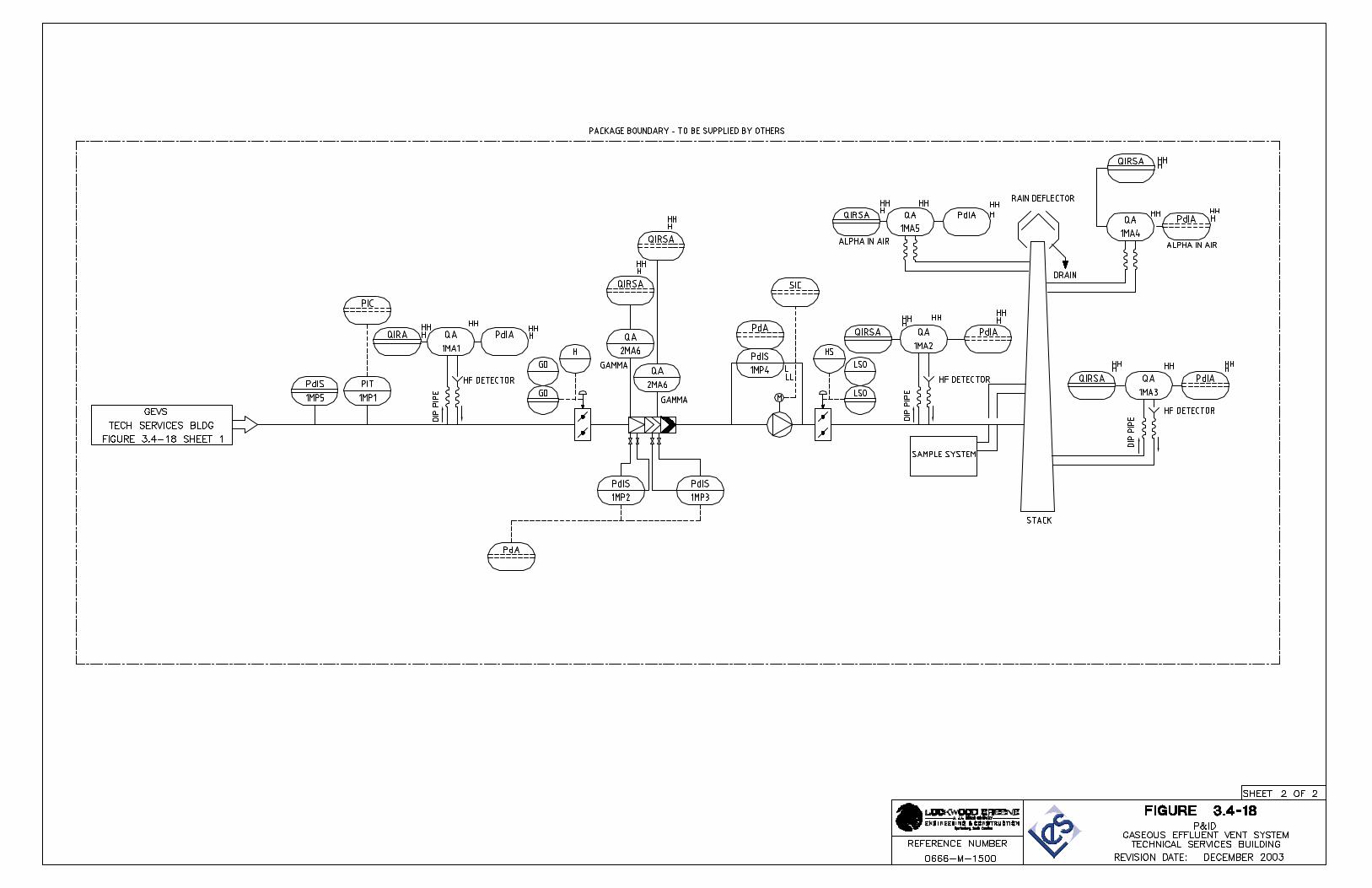
3.3.1.2.2.9 TSB Gaseous Effluent Vent System (GEVS) Room
The TSB GEVS is designed to remove UF6, particulates containing uranium, and hydrogen fluoride (HF) from potentially contaminated process gas streams. Prefilters and High Efficiency Particulate Air filters remove particulates, including uranium particles, and impregnated and activated charcoal filters remove any residual traces of uranium and HF. The TSB GEVS is described in Section 3.4.9, Gaseous Effluent Vent System. The major components of the TSB GEVS are located in the TSB GEVS Room.
This room is approximately 9.6 m (31.5 ft) x 20.0 m (65.6 ft) x 10.0 m (32.8 ft) high and totals 192 m2 (2,067 ft2). It is classified as a Special Purpose Industrial Control area and is separated from the a Special Purpose Industrial Occupancy areas by one-hour fire-rated construction.
NEF Safety Analysis Report December 2003 Page 3.3-7
3.3.1.2.2.10 Mass Spectrometry Laboratory
The Mass Spectrometry Laboratory is designed for the purpose of measuring the isotopic abundance of various uranium isotopes in prepared samples, the bulk comprising hydrolysed uranium hexafluoride.
This room is approximately 10.3 m (33.75 ft) x 20.0 m (65.6 ft) and totals 206 m2 (2,217 ft2). It is classified as a Special Purpose Industrial Occupancy area.
3.3.1.2.2.11 Chemical Laboratory
The Chemical Laboratory is designed for the purpose of analyzing solid and liquid samples taken from all areas of the facility. It includes space for an analytical area, sub sampling area, wash area and weighing area.
This room is approximately 16.2 m (53.2 ft) x 20.0 m (65.6 ft) and totals 324 m2 (3,488 ft2). It is classified as a Special Purpose Industrial Occupancy area. The Sample Storage Room in the Chemical Laboratory is one-hour fire-rated construction.
3.3.1.2.2.12 Environmental Monitoring Laboratory
The Environmental Monitoring Laboratory is designed for the purpose of preparing and analyzing samples associated with safety or regulatory compliance.
This room and associated office space are approximately 17.3 m (56.75 ft) x 19.3 m (63.3 ft) and totals 334 m2 (3,595 ft2). It is classified as a Special Purpose Industrial Occupancy area.
3.3.1.2.2.13 Truck Bay/Shipping and Receiving Area
The Truck Bay is used as a place to load packaged low-level radioactive wastes onto trucks for transportation off site to a licensed processing facility or licensed disposal facility. It is also used for miscellaneous shipping and receiving.
This room is approximately 4.6 m (15.08 ft) x 9.8 m (32.2 ft) and totals 45 m2 (484 ft2). It is classified as a Special Purpose Industrial Occupancy area.
3.3.1.2.2.14 Medical Room
The Medical Room is designed to provide space for a nurse’s station. This room is approximately 5.2 m (17 ft) x 5.4 m (17.75 ft) and totals 28 m2 (301 ft2). It is classified as a Special Purpose Industrial Occupancy area.
3.3.1.2.2.15 Radiation Monitoring Control Room
The Radiation Monitoring Control Room is designed to be the point of demarcation between non-contaminated areas and potentially contaminated areas of the facility. It includes space for a hand and foot monitor, hand washing facilities, safety showers, and boot barrier access.
NEF Safety Analysis Report Revision 2, July 2004 Page 3.3-8
This room is approximately 3.65 m (12 ft) x 8.4 m (27.6 ft) and totals 30 m2 (323 ft2). It is classified as a Special Purpose Industrial Occupancy area.
3.3.1.2.2.16 Break Room
The Break Room has room for vending machines, tables and a small kitchenette. It also serves as an assembly area for emergency planning purposes and has area allocated for the storage of emergency equipment and supplies and emergency monitoring equipment.
This room is approximately 7.3 m (23.9 ft) x 15.0 m (49.25 ft) and totals 110 m2 (1,184 ft2). It is classified as a Special Purpose Industrial Occupancy area.
3.3.1.2.2.17 Control Room
The Control Room and associated support area are approximately 14.4 m (47.25 ft) x 12.6 m (41.3 ft) and totals 181 m2 (1,948 ft2) and is the main monitoring point for the entire facility. It is classified as a Special Purpose Industrial Occupancy area. The Control Room provides all of the facilities for the control of the plant, operational requirements and personnel comfort. It is a permanently manned area and contains the following equipment:
• Overview screen • Control desk • Fire alarm system • Storage facilities • Communication systems.
The Plant Control Systems and the Communications and Alarms System are described in Section 3.5.9, Control Systems and Section 3.5.7, Communication and Alarm Annunciation Systems, respectively.
3.3.1.2.2.18 Training Room
The Training Room and associated support area are approximately 9.7 m (31.8 ft) x 10.6 m (34.75 ft) and totals 103 m2 (1,108 ft2) and is used for Control Room training. It is classified as a Special Purpose Industrial Occupancy area. It has visual and personnel access to the Control Room and contains the following:
• Plant Control System training system • Centrifuge Monitoring System training system • Central Control System switches and servers.
3.3.1.2.2.19 Security Alarm Center
The Security Alarm Center is approximately 7.0 m (23 ft) x 5.6 m (18.3 ft) and totals 39 m2 (420 ft2) and is used as the primary security monitoring station for the facility. It is classified as a Special Purpose Industrial Occupancy area. All electronic security systems are controlled and
NEF Safety Analysis Report Revision 2, July 2004 Page 3.3-9
monitored from this center. These systems include Closed Circuit Television (CCTV), Intrusion Detection and Assessment (IDA), Access Control and radio dispatch.
3.3.1.2.3 Building Construction
The TSB superstructure is of precast/prestressed concrete construction using rectangular columns, rectangular and inverted tee beams, double or single tee roof and floor members and solid wall panels.
The roof structure over the TSB consists of deep precast/prestressed concrete double or single tee members covered with a thin layer of isocyanurate insulation board that provides a barrier between the concrete surface and the single-ply roof membrane. The single ply membrane is then covered by 100 mm (4 in) of dow board insulation, filter fabric and concrete pavers. The tee members are supported by concrete ‘L’ girders around the perimeter and inverted tee girders on interior spans. These, in turn, are supported by concrete columns supported on concrete spread footings. The roof assembly has a minimum combined thermal resistance value of R-20.
Exterior walls are precast insulated concrete panels. These walls act as shear walls to provide lateral support for the structure. The exterior wall assembly has a minimum combined thermal resistance value of R-10. The interior side of the exterior wall is of smooth concrete that has been sealed and painted. Interior non-load bearing walls are constructed of 200 mm (8 in) concrete block with an epoxy painted finish. These walls extend to the underside of the structure where required.
Floors in the TSB technical areas are of exposed concrete with a washable epoxy coating finish. The coatings are designed to resist process chemicals, decontamination agents and radiation.
3.3.1.3 Cylinder Receipt and Dispatch Building (CRDB)
The overall layout of the CRDB is presented in Figures 3.3-10 through 3.3-12. The CRDB is located between two Separations Building Modules, adjacent to the Blending and Liquid Sampling Area.
3.3.1.3.1 Design Description
The CRDB is approximately 45.9 m (150.6 ft) wide x 246.2 m (807.75 ft) long and 13.0 m (42.7 ft) high and totals 11,300 m2 (121,638 ft2). The entire CRDB is open to the underside of the roof. It is classified as a Storage Occupancy area by the NFPA 101 (NFPA, 1997). It is classified as a Type I Unsprinklered Construction area by the New Mexico Building Code (NMBC, 1997) and as Type I Construction by NFPA 220 (NFPA, 1999). The CRDB is designed to meet the occupant and exiting requirements set by the NFPA 101 (NFPA, 1997) and to meet the construction type classification set by the New Mexico Building Code (NMBC, 1997). The CRDB is separated from the separations modules and Blending and Liquid Sampling Area by one-hour fire-rated construction. The CRDB exterior walls are a minimum one-hour fire-rated construction.
NEF Safety Analysis Report Revision 2, July 2004 Page 3.3-10
3.3.1.3.2 Functional Areas and Major Components
All UF6 feed cylinders and empty product cylinders and uranium byproduct cylinders (UBCs) enter the facility through the CRDB. It is designed to include space for the following:
• Loading and unloading of cylinders • Inventory weighing • Buffer storage of feed cylinders • Preparation and storage of overpack protective packaging • Semi-finished product storage • Final product storage • Prepared cylinder storage.
The majority of the floor area is used as lay-down space for the cylinders, for both storage and preparation. The cylinders are placed on specially designed cradles called stillages to stabilize them while being stored in the CRDB.
Cylinders are delivered to the facility in transport trucks. The trucks enter the CRDB through the main vehicle loading bay, located between column lines 40 and 41, which is equipped with vehicle access platforms that aid with cylinder loading and unloading. Two double girder bridge cranes handle the cylinders within the CRDB. Each crane spans 1/2 the width and runs the full length of the building.
After delivery, the cylinders are processed for receipt as either empty UBCs (48-in cylinders) or empty product cylinders (30-in or 48-in cylinders) or UF6 feed cylinders (48-in cylinders). They are inspected and weighed and moved to their appropriate locations. UF6 feed cylinders are delivered to a storage area in the CRDB.
When required for processing, the cylinders, which have been placed in storage areas are moved by the overhead cranes to the rail transporter located between column lines 15.4 and 16 of the CRDB. The CRDB rail transporter transports cylinders to the main rail transporter in the Blending and Liquid Sampling Area, which then delivers the cylinders to their required locations throughout the facility. Cylinders are removed from the facility in the same fashion.
3.3.1.3.3 Building Construction
The CRDB superstructure is designed to be missile resistant and is of precast/prestressed concrete construction using rectangular columns, rectangular and inverted tee beams, double or single tee roof and floor members and solid wall panels.
The two double girder bridge cranes are supported by a steel girder crane runway, supported by the precast concrete columns.
The roof structure over the CRDB consists of deep precast/prestressed concrete double or single tee members covered with a thin layer of isocyanurate insulation board that provides a barrier between the concrete surface and the single-ply roof membrane. The single ply membrane is then covered by 100 mm (4 in) of dow board insulation, filter fabric and concrete pavers. The tee members are supported by concrete ‘L’ girders around the perimeter and inverted tee girders on interior spans. These, in turn, are supported by concrete columns
NEF Safety Analysis Report Revision 2, July 2004 Page 3.3-11
supported on concrete spread footings. The roof assembly has a minimum combined thermal resistance value of R-20.
Exterior walls are precast insulated concrete panels. These walls act as shear walls to provide lateral support for the structure. The exterior wall assembly has a minimum combined thermal resistance value of R-10. The interior side of the exterior wall is smooth concrete, which has been sealed and painted. Interior non-load bearing walls are constructed of 200 mm (8 in) concrete block with an epoxy painted finish. These walls extend to the underside of the structure where required.
The floor areas of the CRDB, which are used as a part of the centrifuge transport path, have a floor profile quality classification of flat in accordance with ACI 117-90 (ACI, 1990a) to aid in the transport of assembled centrifuges.
Floors in the CRDB are of exposed concrete with a washable epoxy coating finish. The coatings are designed to resist process chemicals, decontamination agents and radiation.
3.3.1.4 Centrifuge Assembly Building
The overall layout of the Centrifuge Assembly Building (CAB) is presented in Figures 3.3-13 through 3.3-16. The Centrifuge Assembly Building is located adjacent to the Cylinder Receipt and Dispatch Building.
3.3.1.4.1 Design Description
The CAB is approximately 50.9 m (167 ft) wide x 195.5 m (641.4 ft) long and ranges from 11 m (36.08 ft) to 16 m (52.5 ft) high. It totals approximately 11,364 m2 (122,322 ft2). The entire CAB is open to the underside of the roof. It is classified as a Special Purpose Industrial Occupancy area by NFPA 101 (NFPA, 1997). It is classified as a Type I Unsprinklered Construction area by the New Mexico Building code (NMBC, 1997). The CAB is designed to meet the occupant and exiting requirements set by NFPA 101 (NFPA, 1997) and to meet the construction type classifications set by the New Mexico Building code (NMBC, 1997) and as Type I Construction by NFPA 220 (NFPA, 1999). The CAB is separated from the CRDB one-hour fire-rated construction.
The Centrifuge Assembly Building is used for the assembly, inspection and mechanical testing of the centrifuges prior to installation in the Cascade Halls of the Separations Building Modules and introduction of UF6. Centrifuge assembly operations are undertaken in clean room conditions. The building is divided into the following distinct areas:
• Centrifuge Component Storage Area • Centrifuge Assembly Area ‘A’ • Centrifuge Assembly Area ‘B’ • Assembled Centrifuge Storage Area • Building Office Area • Centrifuge Test and Post Mortem Facilities.
NEF Safety Analysis Report Revision 2, July 2004 Page 3.3-12
3.3.1.4.2 Functional Areas and Major Components
3.3.1.4.2.1 Centrifuge Component Storage Area
The Centrifuge Component Storage Area serves as the initial receipt location for the centrifuge parts. It is designed to store up to four weeks stock of centrifuge components delivered from Europe. These components are delivered by truck in specifically designed containers, which are then packed into International Organization for Standardization (ISO) freight containers. The containers are off-loaded via fork lift truck and placed in the storage area through one of two roll up doors located at the end of the CAB.
Because the assembly operations are undertaken in clean room conditions, the centrifuge component containers are cleaned in a washing facility located within the Centrifuge Component Storage Area, prior to admission to the Centrifuge Assembly Area. The Centrifuge Component Storage Area also acts as an acclimatization area to allow components to equilibrate with the climatic conditions of the Centrifuge Assembly Area.
Transfer of components and personnel between the Centrifuge Component Storage Area and the Centrifuge Assembly Area is via an airlock to prevent ingress of airborne contaminants.
3.3.1.4.2.2 Centrifuge Assembly Area
Centrifuge components are assembled into complete centrifuges in this area. Assembly operations are carried out on two parallel production lines, A and B.
The centrifuge operates in a vacuum, therefore, centrifuge assembly activities are undertaken in clean room conditions, ISO Class 5 according to ISO 14644-1:1999E (ISO, 1999), to prevent ingress of volatile contaminants which would have a detrimental effect on centrifuge performance. Prior to installation into the cascade, the centrifuge has to be conditioned, which is done in the Centrifuge Assembly Area prior to storage in the Assembled Centrifuge Storage Area.
Local jib cranes are installed in certain areas and impose less than a 500 kg (1100 lb) load. The Centrifuge Assembly Area is separated from other areas by one-hour fire-rated construction.
3.3.1.4.2.3 Assembled Centrifuge Storage Area
Assembled and conditioned centrifuges are stored in the Assembled Centrifuge Storage Area prior to installation.
During construction of the facility, a separate installation team will access this area and transfer the assembled and conditioned centrifuges to the Cascade Halls for deployment.
Centrifuges are routed via a covered corridor that links the Assembled Centrifuge Storage Area with the CRDB. The covered corridor has the same standard of floor as the Assembled Centrifuge Storage Area.
NEF Safety Analysis Report Revision 2, July 2004 Page 3.3-13
3.3.1.4.2.4 Building Office Area
A general office area is located adjacent to the Centrifuge Assembly Area. It contains the main personnel entrance to the building as well as entrances to the Centrifuge Component Storage Area and Centrifuge Assembly Area. It is a two-story area that includes the following:
• Offices • Change Rooms - The change rooms provide space where employees can dress in
protective clothing as required • Break Room • Maintenance Area • Chemical Storage Area • Battery Charging Area.
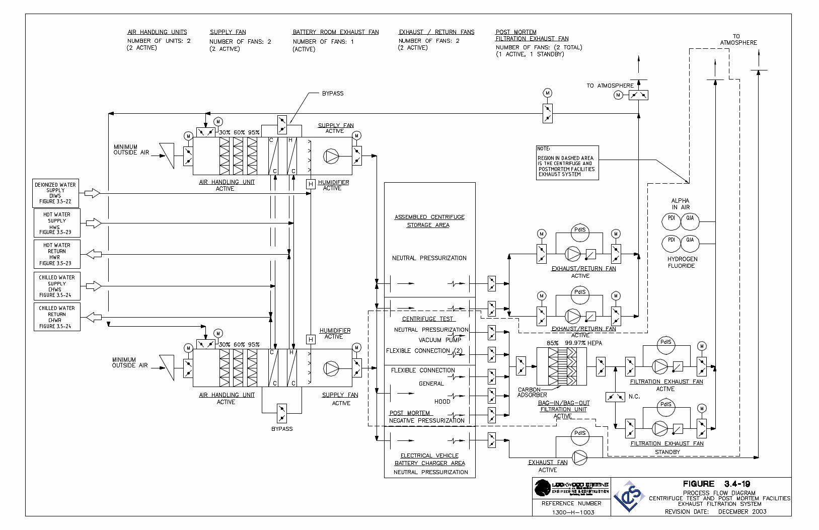
3.3.1.4.2.5 Centrifuge Test and Post Mortem Facilities
The Centrifuge Test Facility is designed to:
• Provide a means of functionally testing the performance of production centrifuges to ensure compliance with design parameters
• Investigate production and operational problems.
This area consists of two test positions. The Centrifuge Post Mortem Facility is designed for investigating problems with production centrifuges. Based on 30 years of European experience, the demand for centrifuge post mortems is infrequent.
The principal functions of the Centrifuge Post Mortem Facility are:
• To facilitate dismantling of contaminated centrifuges using equipment and processes, which minimize the potential to contaminate personnel or adjacent facilities
• To prepare potentially contaminated components and materials for transfer to the TSB prior to disposal.
Centrifuges are brought into the facility on a specially designed transport cart via an airlock entry. The facility is also equipped with radiological monitoring devices, toilets and washing facilities, and hand, foot and clothing personnel monitors to detect surface contamination.
The Centrifuge Post Mortem Facility includes a centrifuge dismantling area and an inspection area. The centrifuge dismantling area includes a stand onto which the centrifuge to be dismantled is mounted providing access to the top and bottom of the centrifuge. A local jib crane is located over the stand to enable removal of the centrifuge from the transport cart and facilitate loading onto the stand. The inspection area includes an inspection bench, portable lighting, a microscope, an endoscope and a digital video/camera.
NEF Safety Analysis Report Revision 2, July 2004 Page 3.3-14
3.3.1.4.3 Building Construction
The CAB superstructure is designed of precast/prestressed concrete construction using rectangular columns, rectangular and inverted tee beams, double or single tee roof and floor members and solid wall panels.
The roof structure over the CAB consists of deep precast/prestressed concrete double or single tee members covered with a thin layer of isocyanurate insulation board that provides a barrier between the concrete surface and the single-ply roof membrane. The single ply membrane is then covered by 100 mm (4 in) of dow board insulation, filter fabric and concrete pavers. The tee members are supported by concrete ‘L’ girders around the perimeter and inverted tee girders on interior spans. These will, in turn, be supported by concrete columns supported on concrete spread footings. The roof assembly has a minimum combined thermal resistance value of R-20.
Exterior walls are precast insulated concrete panels. These walls act as shear walls to provide lateral support for the structure. The exterior wall assembly has a minimum combined thermal resistance value of R-10. The interior side of the exterior wall is smooth concrete that has been sealed and painted.
Interior non-load bearing walls are constructed of 200 mm (8 in) concrete block with an epoxy painted finish. These walls extend to the underside of the structure where required.
The floors of the CAB Assembled Centrifuge Storage Area have a floor profile quality classification of flat in accordance with ACI 117-90 (ACI, 1990a) to aid in the transport of assembled centrifuges.
Floors in the CAB are of exposed concrete with a washable epoxy coating finish. The coatings are designed to resist process chemicals, decontamination agents and radiation.
The Centrifuge Test Facility Area is separated from other areas by one-hour fire-rated construction.
3.3.1.5 Blending and Liquid Sampling Area
The Blending and Liquid Sampling Area is shown in Figure 3.3-17. The Blending and Liquid Sampling Area is adjacent to the CRDB and is located between two Separations Building Modules.
3.3.1.5.1 Design Description
The Blending and Liquid Sampling Area is approximately 45.9 m (150.6 ft) wide x 33.5 m (109.9 ft) long and 10.0 m (32.8 ft) high and totals 1,538 m2 (16,555 ft2). The entire area is open to the underside of the roof. It is classified as a Special Purpose Industrial Occupancy area by NFPA 101 (NFPA, 1997). It is classified as a Type I Unsprinklered Construction area by the New Mexico Building code (NMBC, 1997) and as Type I Construction by NFPA 220 (NFPA, 1999). The Blending and Liquid Sampling Area is designed to meet the occupant and exiting requirements set by the NFPA 101 (NFPA, 1997) and to meet the construction type classification set by the New Mexico Building code (NMBC, 1997). The Blending and Liquid Sampling Area is separated from the UF6 Handling Areas by one-hour fire-rated construction.
NEF Safety Analysis Report Revision 2, July 2004 Page 3.3-15
3.3.1.5.2 Functional Areas and Major Components
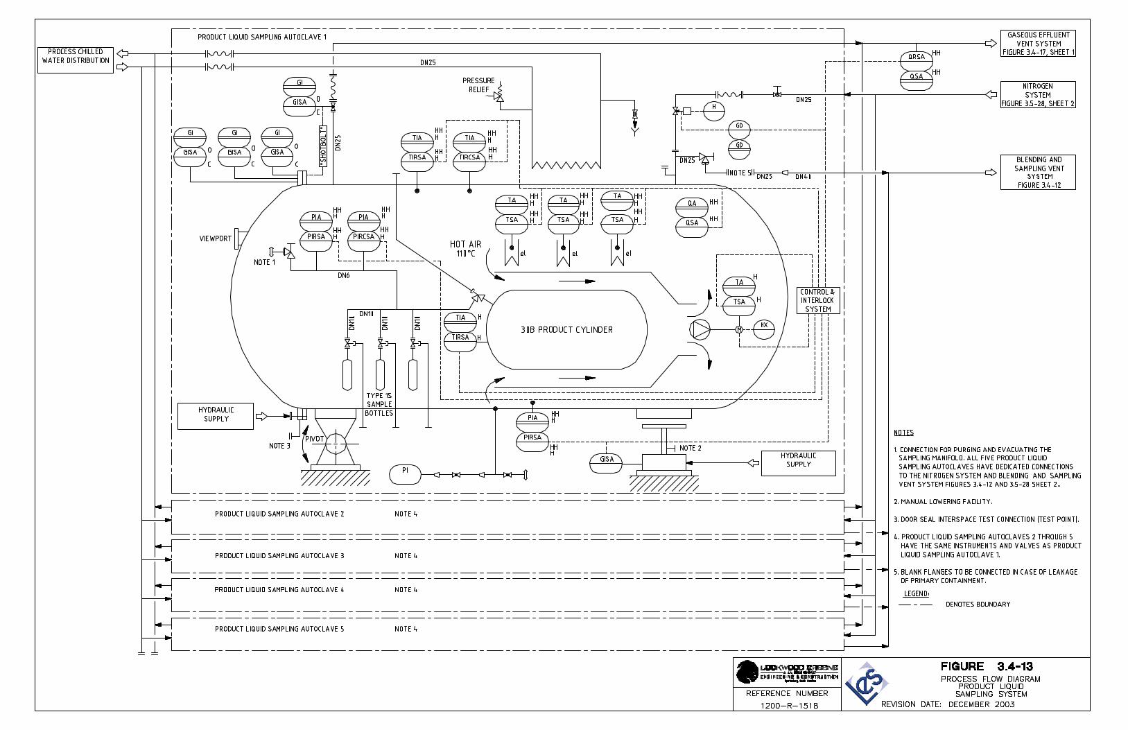
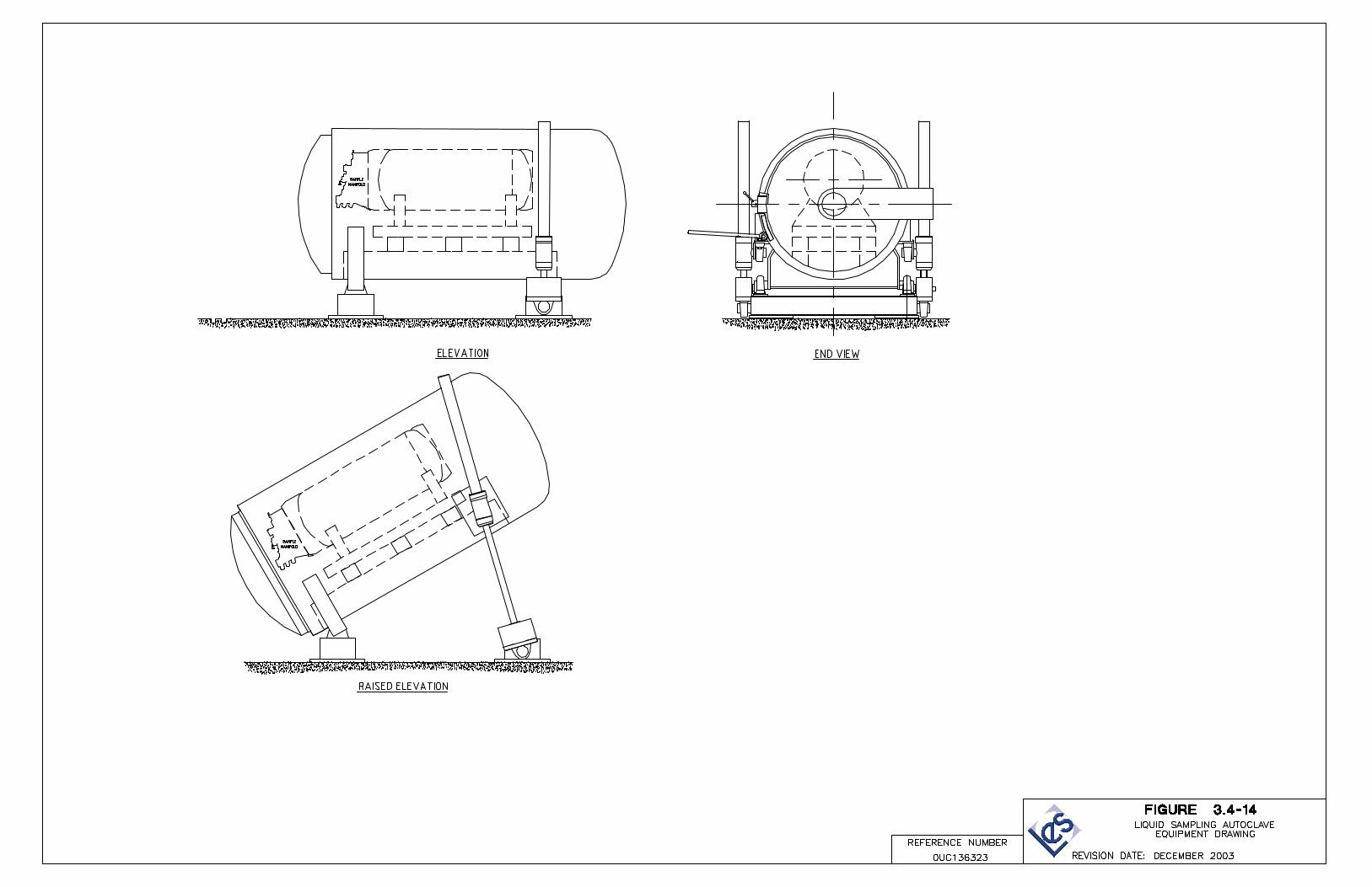
The primary function of the Blending and Liquid Sampling Area is to provide means to fill 30B cylinders with UF6 at a required 235U concentration level and to obtain samples of the homogenized liquid UF6. The area contains the major components associated with the Product Blending System and the Product Liquid Sampling System. The Product Blending System is described in Section 3.4.6, Product Blending System. The Product Liquid Sampling System is described in Section 3.4.7, Product Liquid Sampling System.
3.3.1.5.3 Building Construction
The Blending and Liquid Sampling Area superstructure is designed to be missile resistant and is of precast/prestressed concrete construction using rectangular columns, rectangular and inverted tee beams, double or single tee roof and floor members and solid wall panels.
The roof structure over the Blending and Liquid Sampling Area consists of deep precast/prestressed concrete double or single tee members covered with a thin layer of isocyanurate insulation board that provides a barrier between the concrete surface and the single-ply roof membrane. The single ply membrane is then covered by 100 mm (4 in) of dow board insulation, filter fabric and concrete pavers. The tee members are supported by concrete ‘L’ girders around the perimeter and inverted tee girders on interior spans. These, in turn, are supported by concrete columns supported on concrete spread footings. The roof assembly has a minimum combined thermal resistance value of R-20.
Exterior walls are precast insulated concrete panels. These walls act as shear walls to provide lateral support for the structure. The exterior wall assembly has a minimum combined thermal resistance value of R-10. The interior side of the exterior wall is smooth concrete, which has been sealed and painted.
Interior non-load bearing walls are constructed of 200 mm (8 in) concrete block with an epoxy painted finish. These walls extend to the underside of the structure where required.
Floors in the Blending and Liquid Sampling Area are of exposed concrete with a washable epoxy coating finish. The coatings are designed to resist process chemicals, decontamination agents and radiation.
3.3.1.6 Uranium Byproduct Cylinder (UBC) Storage Pad
The facility utilizes an area outside of the CRDB for storage of UBCs, which contain UF6 that is depleted in 235U. The tails are stored under vacuum in corrosion resistant Type 48Y cylinders. The UBC Storage Pad will also be used to store empty feed cylinders that are not immediately reconnected to the facility. The UBC Storage Pad is shown on Figure 3.3-1, Facility Buildings and Areas.
3.3.1.6.1 Design Description
The UBC Storage Pad is designed to provide storage for UBCs and six months of empty feed cylinders. Approximately 625 UBC per year are filled for storage. The UBC Storage pad is sized to accommodate 15,727 cylinders (capacity equivalent to 30 years of facility operation).
NEF Safety Analysis Report Revision 2, July 2004 Page 3.3-16
These cylinders are stacked two high. Concrete saddles are used to store the cylinders approximately 200 mm (8 in) above ground level. The UBC Storage Pad occupies approximately 8.50 ha (21 acres).
3.3.1.6.2 Functional Areas and Major Components
The UBC Storage Pad layout is based on moving the cylinders with cranes and flatbed trucks. Flatbed trucks are used to move the cylinders from the CRDB to the UBC Storage Pad. A double girder Gantry crane is used to remove the cylinders from the flatbed trucks and place them in the UBC Storage Pad. The Gantry crane is designed to double stack the cylinders in the storage area.
3.3.1.6.3 Construction
The UBC Storage Pad is constructed of a concrete pad with a dedicated collection and drainage system. Vehicle crash barriers are located along the site roads outside of the Controlled Access Area adjacent to the storage area. The entire area is fenced for security and radiological protection purposes.
3.3.1.7 Central Utilities Building
The Central Utilities Building (CUB) is shown on Figure 3.3-18.
3.3.1.7.1 Design Description
The CUB is approximately 24.8 m (81.3 ft) wide x 80.8 m (265.08 ft) long and 10 m (32.8 ft) high and totals 1962 m2 (21,119 ft2). It is classified as a Special Purpose Industrial Occupancy by NFPA 101 (NFPA, 1997). It is classified as a Type IIIN Unprotected, Sprinklered Construction area by the New Mexico Building Code (NMBC, 1997) and as Type II Construction by NFPA 220 (NFPA, 1999). The Central Utilities Building is designed to meet the occupant and exiting requirements set by the NFPA 101 (NFPA, 1997) and set by the New Mexico Building Code (NMBC, 1997).
3.3.1.7.2 Functional Areas and Major Components
The Central Utilities Building houses two diesel generators, which provide the site with standby power. The Standby Generator System is discussed in Section 3.5.10, Standby Diesel Generator System. The building contains day tanks, switchgear, and control panels. The rooms housing the diesels are constructed independent of each other with adequate provisions made for maintenance, equipment removal and equipment replacement, by roll-up and access doors.
The diesel fuel unloading area provides tanker truck access to the two above ground tanks, which provide diesel fuel storage. Secondary containment is provided to contain spills or leaks from the above ground diesel fuel tanks.
NEF Safety Analysis Report Revision 2, July 2004 Page 3.3-17
The CUB also houses the cooling water chillers and pumps, boiler room, hot water boilers and pumps, deionized water systems and air compressors. These systems are described in Sections 3.5.5, Cooling Water System, 3.5.4, Water Supply, and 3.5.3, Compressed Air System, respectively.
3.3.1.7.3 Building Construction
The Central Utilities Building superstructure is designed of structural steel framing.
The roof structure consists of metal decking over structural steel framing. The metal decking is covered with a built-up roof system. The roof assembly has a minimum combined thermal resistance value of R-20.
Exterior walls consist of a metal panel system. The exterior wall assembly has a minimum combined thermal resistance value of R-10.
Interior non-load bearing walls are constructed of 200 mm (8 in) concrete block with an epoxy painted finish. These walls extend to the underside of the structure where required.
Floors consist of exposed concrete with a washable epoxy coating finish.
3.3.1.8 Administration Building
3.3.1.8.1 Design Description
The Administration Building is near the TSB. It is approximately 1403 m2 (15,102 ft2) and 6.0 m (19.8 ft) high. It is classified as a New Business Occupancy area by the NFPA 101 (NFPA,1997) and is classified as a Type IIIN Unprotected Construction area by the New Mexico Building Code (NMBC, 1997) and as Type II Construction by NFPA 220 (NFPA, 1999). The Administration Building is designed to meet the occupant, and exiting requirements set by the NFPA 101 (NFPA,1997) and by the New Mexico Building Code (NMBC, 1997). The entire building is sprinklered.
3.3.1.8.2 Functional Areas and Major Components
The general office areas and the Entry Exit Control Point (EECP) for the facility are located in the Administration Building. All personnel access to the facility occurs at this location. Vehicular traffic passes through a security checkpoint before being allowed to park. Parking is located outside of the Controlled Access Area (CAA) security fence. Personnel enter the Administration Building and general office areas via the main lobby.
Personnel requiring access to facility areas or the CAA must pass through the EECP. The EECP is located at the rear of the main lobby and is designed to facilitate and control passage of authorized facility personnel and visitors to and from the CAA. Personnel entering the security Controlled Access Area are required to undergo, at a minimum, the following security screening at the EECP:
• Positive Identification – photo badge and/or biometrics • Verification of access authorization
NEF Safety Analysis Report Revision 2, July 2004 Page 3.3-18
• Inspection of persons for unauthorized material (pass through a magnetometer) • Inspection of all hand carried packages (x-ray screening).
In the main lobby, employees receive their badges and proceed through a turnstile into the office area or the EECP. Visitors check-in at the main lobby, where a receptionist notifies plant personnel of their arrival.
Entry to the facility areas from the Administration Building is only possible through the EECP.
Approximately 50 work locations are provided for the plant office staff. The office environment consists of private, semiprivate, and open office space. The lobby is designed to also act as an assembly area for emergency planning purposes. Area has been allocated for the storage of emergency equipment and supplies and emergency monitoring equipment. It also contains a kitchen, break room, conference rooms, and building service facilities such as a mechanical equipment room. An open office layout allows for flexibility in space allocation.
3.3.1.8.3 Building Construction
The Administration Building superstructure is designed of structural steel framing.
The roof structure consists of metal decking over structural steel framing. The metal decking is covered with a built-up roof system. The roof assembly has a minimum combined thermal resistance value of R-20.
Exterior walls consist of a combination of architectural metal panels and a curtain wall glazing system. The exterior wall assembly has a minimum combined thermal resistance value of R-10. The interior side of the exterior wall is faced with 16 mm (5/8 in) gypsum wallboard.
Interior non-load bearing walls are constructed of 92 mm (4 in) metal studs filled with batt insulation and faced with 16 mm (5/8 in) gypsum wallboard. Walls extend to 150 mm (6 in) above the ceiling or to the underside of the structure where required.
3.3.1.9 Visitor Center
A Visitor Center is located outside of the security fence area.
3.3.1.10 Site Security Buildings
3.3.1.10.1 Design Description
The main Security Building is located at the entrance to the facility. It functions as a security checkpoint for incoming and outgoing traffic. Employees, visitors and trucks that have access approval are screened at the main building. A smaller security station has been placed at the secondary entrance to the site. Vehicle traffic including common carriers, such as mail delivery trucks, are screened at this location.
NEF Safety Analysis Report Revision 2, July 2004 Page 3.3-19
3.3.1.10.2 Functional Areas and Major Components
The main and secondary Security Buildings are located at the entries to the site. They are classified as a New Business Occupancy area by the NFPA 101 (NFPA, 1997) and is classified as Type IIIN Unprotected Construction area by the New Mexico Building Code (NMBC, 1997) and as Type II Construction by NFPA 220 (NFPA, 1999). These buildings are designed to meet the occupant and exiting requirements set by the NFPA 101 (NFPA, 1997) and the construction type classifications set by the New Mexico Building Code (NMBC, 1997).
3.3.1.10.3 Building Construction
The Security Building superstructures are designed of structural steel framing.
The roof structures consist of metal decking over structural steel framing. The metal decking is covered with a built-up roof system. The roof assembly has a minimum combined thermal resistance value of R-20.
Exterior walls consist of a combination of architectural metal panels and glazing. The exterior wall assembly has a minimum combined thermal resistance value of R-10. The interior side of the exterior wall is faced with 16 mm (5/8 in) gypsum wallboard.
Interior non-load bearing walls are constructed of 92 mm (4 in) metal studs filled with batt insulation and faced with 16 mm (5/8 in) gypsum wallboard. Walls extend to 150 mm (6 in) above the ceiling or to the underside of the structure where required.
Floors in the Security Buildings consist of sealed concrete.
3.3.2 Structural Design Criteria
The structural and mechanical design load criteria are based on the environmental and geologic features of the National Enrichment Facility site identified in Section 3.2, Site Description, and the data presented in the accepted Industry Codes and Standards. The design criteria meets the applicable baseline design criteria established in 10 CFR 70.64, Requirements for new facilities or new processes at existing facilities (CFR, 2003). The design is based on the codes and loads discussed below.
As part of the Integrated Safety Analysis for external events, the following structures (buildings and areas) were determined to be safety significant and are required to withstand the design basis natural phenomena hazards and external hazards defined in Section 3.2:
• Separations Building Modules (UF6 Handling Area, Process Services Area, and Cascade Halls)
• Blending and Liquid Sampling Area • Cylinder Receipt and Dispatch Building • TSB • Centrifuge Test Facility.
NEF Safety Analysis Report Revision 2, July 2004 Page 3.3-20
A. Safety significant structures shall be designed to withstand the effects of external events (i.e., seismic, tornado and high winds, tornado missiles, snow and ice load, and maximum local precipitation) reflected in Section 3.2.
B. The UF6 Handling Area, Cascade Hall, Blending and Liquid Sampling Area, and Ventilated Room shall be designed and maintained such that leakage is maintained within the values determined in Integrated Safety Analysis (ISA) consequence calculations.
C. The UBC Storage Pad shall be designed to preclude flooding due to maximum local precipitation reflected in Section 3.2.
D. Above ground liquid storage tanks and water impoundments shall be designed such that they do not pose a flooding risk that could damage critical structures and/or systems under an assumed catastrophic failure and release of full contents (may be shown either by design, amount of contents or physical location).
Items relied on for safety (IROFS) associated with facility structures are listed in Section 3.8, IROFS.
3.3.2.1 Codes and Standards
The following codes and standards are generally applicable to the structural design of the National Enrichment Facility:
• New Mexico Building Code (NMBC, 1997) • Uniform Building Code (UBC, 1997) • ASCE 7-98, Minimum Design Loads for Buildings and Other Structures (ASCE, 1998) • ACI 318-99, Building Code Requirements for Structural Concrete (ACI, 1999) • ACI 349-90, Code Requirements for Nuclear Safety Related Concrete Structures (ACI,
1990b) • AISC Manual of Steel Construction, Ninth Edition (AISC, 1989) • PCI Design Handbook, Fifth Edition (PCI, 1999) • American Society of Testing and Materials (ASTM).
3.3.2.2 Structural Design Loads
3.3.2.2.1 Wind Loadings
The determination of wind pressure loadings and the design for wind loads for all safety significant structures and components exposed to wind are based on the requirements of ASCE 7-98 (ASCE, 1998). The determination of wind pressure loadings and the design for wind loads for all other structures and components exposed to wind are based on the requirements of the Uniform Building Code (UBC, 1997), Chapter 16 which further refers to the wind design requirements of ASCE 7-98, Section 6.0 (ASCE, 1998). The design wind for structures having no safety significance is based on a 50-year period of recurrence. The basic wind speed is 130 km/hr (80 mi/hr). The wind speed is based on an Exposure C category which is for open terrain
NEF Safety Analysis Report December 2003 Page 3.3-21
with scattered obstruction areas as given in the Uniform Building Code (UBC, 1997). For structures that are safety significant, the design wind speed is 252 km/hr (157 mi/hr). This wind speed is based on a 100,000-year period of recurrence. All buildings on the NEF site are less than 18.2 m (60 ft) in height.
The design wind pressures and forces on the total building area calculated in accordance with procedures outlined in Section 6.4.2 of ASCE 7-98 (ASCE, 1998). The wind pressures acting on the main wind-force resisting systems are determined using the following formulas:
Velocity Pressure qz = 0.00256KzKztKdV2I (lb/ft2) (Eq. 3.3-1)
Design Pressure p = qGCp – qi(GCpi) (lb/ft2) (Eq. 3.3-2)
Where:
qz = velocity pressure evaluated at height z above ground, psf
Kz = velocity pressure exposure coefficient evaluated at height z
Kzt = topographic factor
Kd = wind directionality factor
V = basic wind speed, mi/hr (corresponds to a 3-second gust speed at 10.1 m (33 ft) in exposure category C)
I = importance factor = 1.00. Safety significant structures have an increased safety factor due to design probability of 1.0E-5 of wind
p = design wind pressure, lb/ft2
G = gust effect factor
Cp = external pressure coefficient
qi = velocity pressure for internal pressure determination
GCpi = product of internal pressure coefficient and gust factor
The design of wind pressures and forces on building components and cladding are calculated in accordance with procedures outlined in Section 6.5.12.4 of ASCE 7-98 (ASCE, 1998). Wind pressures on building components and cladding are determined using the following formula:
p = qh[(GCp) – (GCpi)] (lb/ft2) (Eq. 3.3-3)
Where:
p = design wind pressure, lb/ft2
qh = velocity pressure at roof height z = h (mean roof height), lb/ft2
G = gust effect factor
Cp = external pressure coefficient
GCpi = product of internal pressure coefficient and gust factor
The design wind pressure on other structures is calculated in accordance with procedures outlines in Chapter 16, Division III of the Uniform Building Code (UBC, 1997). The design wind pressure is determined using the following formula:
NEF Safety Analysis Report December 2003 Page 3.3-22
Design Pressure P = CeCqqsIw (lb/ft2) (Eq. 3.3-4) Where:
Ce = combined height, exposure and gust factor coefficient from Table 16-G Cq = pressure coefficient from Table 16-H qs = wind stagnation pressure at standard height of 10 m (33 ft) Iw = wind importance factor from Table 16-K Occupancy Category
The design wind pressures and forces on the total building area calculated in accordance with procedures outlined in Section 1621.3 of the Uniform Building Code (UBC, 1997). The design of wind pressures and forces on building components and cladding are calculated in accordance with procedures outlined in Section 1622 of the Uniform Building Code (UBC,1997).
3.3.2.2.2 Cyclonic Loadings
3.3.2.2.2.1 Tornado
The safety significant structures and components exposed to wind are designed to withstand tornado loadings including tornado-generated missiles. The tornado parameters are based on a 100,000-year period of recurrence.
The design parameters applicable to the design tornado are as follows:
Design wind speed: 302 km/hr (188 mi/hr)
Radius of damaging winds: 130 m (425 ft)
Atmospheric pressure change (APC): -390 kg/m2 (-80 lb/ft2)
Rate of APC: -146 kg/m2/s (-30 lb/ft2/s)
The wind pressures are determined and applied to the structures and buildings in the same manner as the wind loads described in Section 3.3.2.2.1, Wind Loadings. Internal pressure differential due to atmospheric pressure change is considered. The procedures used for transforming the impactive missile loadings into effective loads are discussed in Section 3.3.2.2.3, Projectile Protection.
3.3.2.2.2.2 Hurricane
The NEF site is approximately 805 km (500 mi) inland from the nearest coastline. Hurricane wind is not a governing condition in comparison to normal wind and tornado wind.
NEF Safety Analysis Report December 2003 Page 3.3-23
3.3.2.2.3 Projectile Protection
Projectile protection is provided for all equipment, systems and components in the safety significant areas such that internally generated or externally generated missiles will not cause the release of radioactive materials or prevent the safe and orderly shutdown of the facility.
3.3.2.2.3.1 Internal Projectiles
Internally generated projectiles are not a concern in the Separations Building. The types of equipment that are potential sources of projectiles are blowers, fans, pumps, compressors, high pressure gas cylinders and the centrifuges. The centrifuges have been tested to mechanical failure. These tests have demonstrated that the centrifuge casing will contain any internal projectiles generated as a result of a centrifuge failure. Likewise, in the Separations Building and other safety significant areas of the facility, the components of the other pieces of rotating equipment located in these areas that could become missiles do not have sufficient energy to break through their respective housings or casings. Also, there are no high energy piping systems in these areas that could be the source of jet impingements or pipe whip. High pressure gas cylinders will be handled and stored on site to preclude the generation of internal missiles.
3.3.2.2.3.2 External Projectiles
The only external projectiles that have been identified as a design consideration are tornado-generated missiles. The barriers and buildings protecting equipment and components in the safety significant areas are designed to withstand and absorb tornado generated missile impact loads without causing any damage to the protected equipment and components.
Aircraft crashes are not credible events for the NEF site. Additional information concerning aircraft crashes is found in Section 3.2.
A. Tornado-Generated Missiles
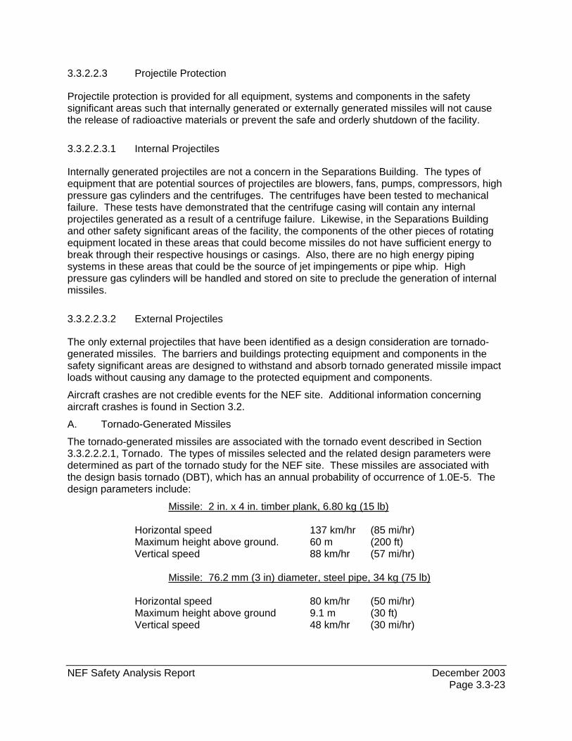
The tornado-generated missiles are associated with the tornado event described in Section 3.3.2.2.2.1, Tornado. The types of missiles selected and the related design parameters were determined as part of the tornado study for the NEF site. These missiles are associated with the design basis tornado (DBT), which has an annual probability of occurrence of 1.0E-5. The design parameters include:
Missile: 2 in. x 4 in. timber plank, 6.80 kg (15 lb) Horizontal speed 137 km/hr (85 mi/hr) Maximum height above ground. 60 m (200 ft) Vertical speed 88 km/hr (57 mi/hr)
Missile: 76.2 mm (3 in) diameter, steel pipe, 34 kg (75 lb)
Horizontal speed 80 km/hr (50 mi/hr) Maximum height above ground 9.1 m (30 ft) Vertical speed 48 km/hr (30 mi/hr)
NEF Safety Analysis Report December 2003 Page 3.3-24
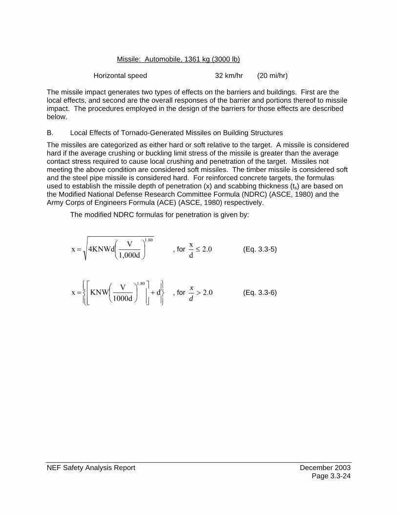
Missile: Automobile, 1361 kg (3000 lb)
Horizontal speed 32 km/hr (20 mi/hr)
The missile impact generates two types of effects on the barriers and buildings. First are the local effects, and second are the overall responses of the barrier and portions thereof to missile impact. The procedures employed in the design of the barriers for those effects are described below.
B. Local Effects of Tornado-Generated Missiles on Building Structures
The missiles are categorized as either hard or soft relative to the target. A missile is considered hard if the average crushing or buckling limit stress of the missile is greater than the average contact stress required to cause local crushing and penetration of the target. Missiles not meeting the above condition are considered soft missiles. The timber missile is considered soft and the steel pipe missile is considered hard. For reinforced concrete targets, the formulas used to establish the missile depth of penetration (x) and scabbing thickness (ts) are based on the Modified National Defense Research Committee Formula (NDRC) (ASCE, 1980) and the Army Corps of Engineers Formula (ACE) (ASCE, 1980) respectively.
The modified NDRC formulas for penetration is given by:
801
1,000dV4KNWd x
.
⎟⎠
⎞⎜⎝
⎛= , for 0.2
dx
≤ (Eq. 3.3-5)
⎪⎭
⎪⎬⎫
⎪⎩
⎪⎨⎧
+⎥⎥⎦
⎤
⎢⎢⎣
⎡⎟⎠⎞
⎜⎝⎛= d1000d
VKNW x 801.
, for 0.2>dx
(Eq. 3.3-6)
NEF Safety Analysis Report December 2003 Page 3.3-25
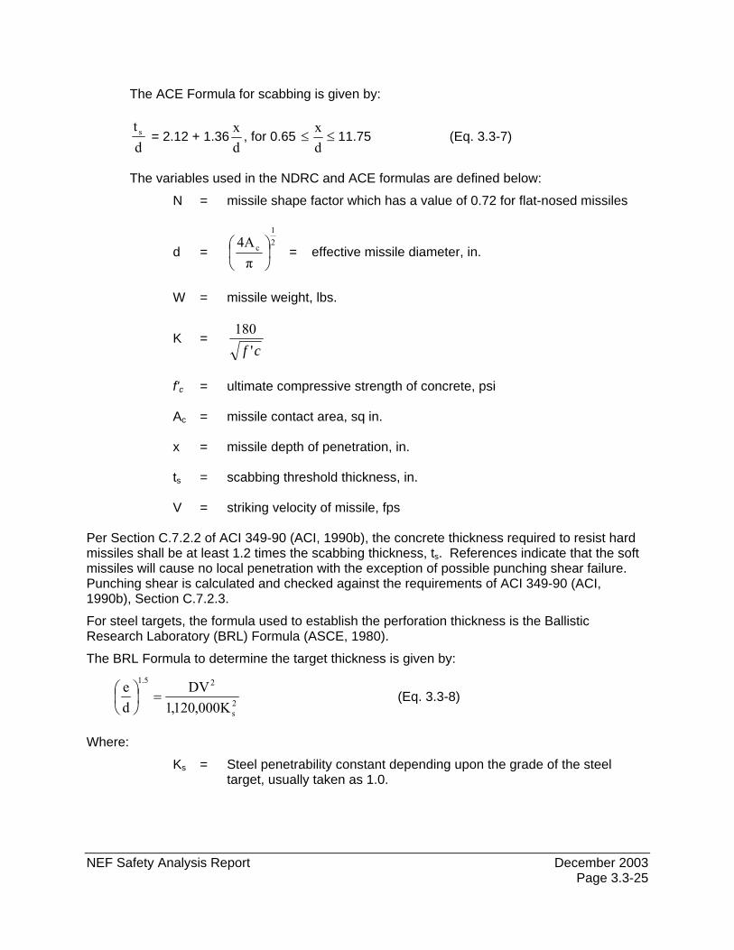
The ACE Formula for scabbing is given by:
dt s = 2.12 + 1.36
dx
, for 0.65 ≤≤dx
11.75 (Eq. 3.3-7)
The variables used in the NDRC and ACE formulas are defined below:
N = missile shape factor which has a value of 0.72 for flat-nosed missiles
d = 21
c
π4A
⎟⎠⎞
⎜⎝⎛ = effective missile diameter, in.
W = missile weight, lbs.
K = cf '
180
f'c = ultimate compressive strength of concrete, psi Ac = missile contact area, sq in. x = missile depth of penetration, in. ts = scabbing threshold thickness, in. V = striking velocity of missile, fps Per Section C.7.2.2 of ACI 349-90 (ACI, 1990b), the concrete thickness required to resist hard missiles shall be at least 1.2 times the scabbing thickness, ts. References indicate that the soft missiles will cause no local penetration with the exception of possible punching shear failure. Punching shear is calculated and checked against the requirements of ACI 349-90 (ACI, 1990b), Section C.7.2.3.
For steel targets, the formula used to establish the perforation thickness is the Ballistic Research Laboratory (BRL) Formula (ASCE, 1980).
The BRL Formula to determine the target thickness is given by:
2s
25.1
K000,120,1DV
de
=⎟⎠⎞
⎜⎝⎛ (Eq. 3.3-8)
Where:
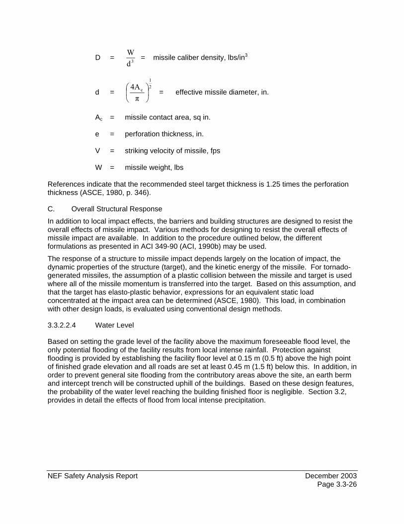
Ks = Steel penetrability constant depending upon the grade of the steel target, usually taken as 1.0.
NEF Safety Analysis Report December 2003 Page 3.3-26
D = 3dW
= missile caliber density, lbs/in3
d = 21
c
π4A
⎟⎠⎞
⎜⎝⎛ = effective missile diameter, in.
Ac = missile contact area, sq in. e = perforation thickness, in. V = striking velocity of missile, fps W = missile weight, lbs References indicate that the recommended steel target thickness is 1.25 times the perforation thickness (ASCE, 1980, p. 346).
C. Overall Structural Response
In addition to local impact effects, the barriers and building structures are designed to resist the overall effects of missile impact. Various methods for designing to resist the overall effects of missile impact are available. In addition to the procedure outlined below, the different formulations as presented in ACI 349-90 (ACI, 1990b) may be used.
The response of a structure to missile impact depends largely on the location of impact, the dynamic properties of the structure (target), and the kinetic energy of the missile. For tornado-generated missiles, the assumption of a plastic collision between the missile and target is used where all of the missile momentum is transferred into the target. Based on this assumption, and that the target has elasto-plastic behavior, expressions for an equivalent static load concentrated at the impact area can be determined (ASCE, 1980). This load, in combination with other design loads, is evaluated using conventional design methods.
3.3.2.2.4 Water Level
Based on setting the grade level of the facility above the maximum foreseeable flood level, the only potential flooding of the facility results from local intense rainfall. Protection against flooding is provided by establishing the facility floor level at 0.15 m (0.5 ft) above the high point of finished grade elevation and all roads are set at least 0.45 m (1.5 ft) below this. In addition, in order to prevent general site flooding from the contributory areas above the site, an earth berm and intercept trench will be constructed uphill of the buildings. Based on these design features, the probability of the water level reaching the building finished floor is negligible. Section 3.2, provides in detail the effects of flood from local intense precipitation.
NEF Safety Analysis Report December 2003 Page 3.3-27
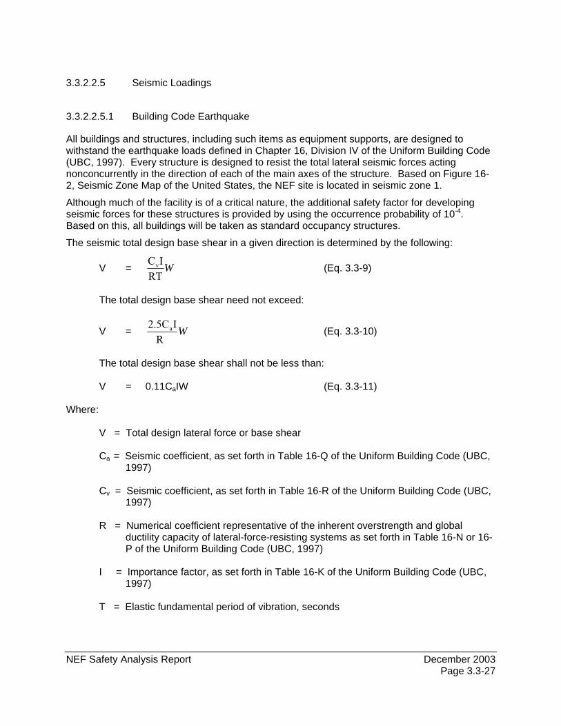
3.3.2.2.5 Seismic Loadings
3.3.2.2.5.1 Building Code Earthquake
All buildings and structures, including such items as equipment supports, are designed to withstand the earthquake loads defined in Chapter 16, Division IV of the Uniform Building Code (UBC, 1997). Every structure is designed to resist the total lateral seismic forces acting nonconcurrently in the direction of each of the main axes of the structure. Based on Figure 16-2, Seismic Zone Map of the United States, the NEF site is located in seismic zone 1.
Although much of the facility is of a critical nature, the additional safety factor for developing seismic forces for these structures is provided by using the occurrence probability of 10-4. Based on this, all buildings will be taken as standard occupancy structures.
The seismic total design base shear in a given direction is determined by the following:
V = WRT
ICv (Eq. 3.3-9)
The total design base shear need not exceed:
V = WR
I2.5Ca (Eq. 3.3-10)
The total design base shear shall not be less than: V = 0.11CaIW (Eq. 3.3-11)
Where:
V = Total design lateral force or base shear
Ca = Seismic coefficient, as set forth in Table 16-Q of the Uniform Building Code (UBC, 1997)
Cv = Seismic coefficient, as set forth in Table 16-R of the Uniform Building Code (UBC,
1997)
R = Numerical coefficient representative of the inherent overstrength and global ductility capacity of lateral-force-resisting systems as set forth in Table 16-N or 16-P of the Uniform Building Code (UBC, 1997)
I = Importance factor, as set forth in Table 16-K of the Uniform Building Code (UBC,
1997)
T = Elastic fundamental period of vibration, seconds
NEF Safety Analysis Report Revision 2, July 2004 Page 3.3-28
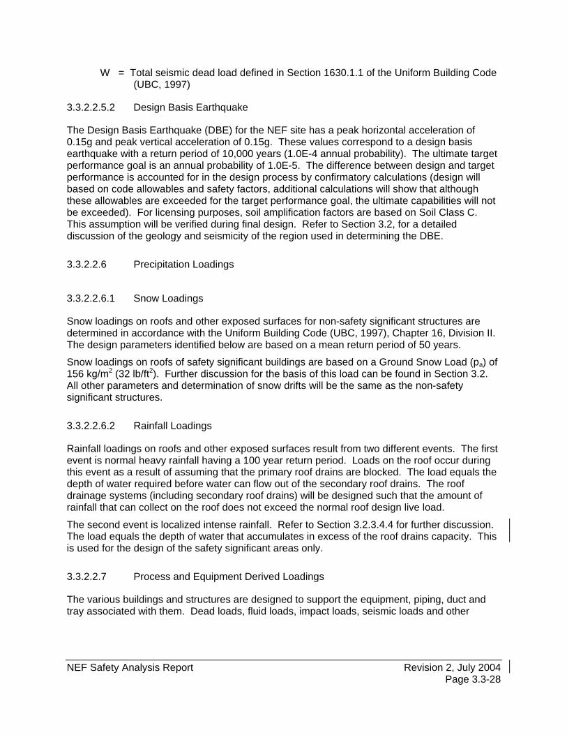
W = Total seismic dead load defined in Section 1630.1.1 of the Uniform Building Code (UBC, 1997)
3.3.2.2.5.2 Design Basis Earthquake
The Design Basis Earthquake (DBE) for the NEF site has a peak horizontal acceleration of 0.15g and peak vertical acceleration of 0.15g. These values correspond to a design basis earthquake with a return period of 10,000 years (1.0E-4 annual probability). The ultimate target performance goal is an annual probability of 1.0E-5. The difference between design and target performance is accounted for in the design process by confirmatory calculations (design will based on code allowables and safety factors, additional calculations will show that although these allowables are exceeded for the target performance goal, the ultimate capabilities will not be exceeded). For licensing purposes, soil amplification factors are based on Soil Class C. This assumption will be verified during final design. Refer to Section 3.2, for a detailed discussion of the geology and seismicity of the region used in determining the DBE.
3.3.2.2.6 Precipitation Loadings
3.3.2.2.6.1 Snow Loadings
Snow loadings on roofs and other exposed surfaces for non-safety significant structures are determined in accordance with the Uniform Building Code (UBC, 1997), Chapter 16, Division II. The design parameters identified below are based on a mean return period of 50 years.
Snow loadings on roofs of safety significant buildings are based on a Ground Snow Load (pa) of 156 kg/m2 (32 lb/ft2). Further discussion for the basis of this load can be found in Section 3.2. All other parameters and determination of snow drifts will be the same as the non-safety significant structures.
3.3.2.2.6.2 Rainfall Loadings
Rainfall loadings on roofs and other exposed surfaces result from two different events. The first event is normal heavy rainfall having a 100 year return period. Loads on the roof occur during this event as a result of assuming that the primary roof drains are blocked. The load equals the depth of water required before water can flow out of the secondary roof drains. The roof drainage systems (including secondary roof drains) will be designed such that the amount of rainfall that can collect on the roof does not exceed the normal roof design live load.
The second event is localized intense rainfall. Refer to Section 3.2.3.4.4 for further discussion. The load equals the depth of water that accumulates in excess of the roof drains capacity. This is used for the design of the safety significant areas only.
3.3.2.2.7 Process and Equipment Derived Loadings
The various buildings and structures are designed to support the equipment, piping, duct and tray associated with them. Dead loads, fluid loads, impact loads, seismic loads and other
NEF Safety Analysis Report December 2003 Page 3.3-29
dynamic loads are accounted for in the design. In addition to the buildings, individual supports are designed to withstand these same types of loads.
3.3.2.2.7.1 Equipment Loads
All pieces of equipment that exceed 454 kg (1,000 lb) dead weight, including contents, are accounted for individually in the design. The remaining equipment is accounted for in the building design by including an appropriate uniform dead load for a particular area.
3.3.2.2.7.2 Piping Loads
Piping loads transmitted through pipe racks to the building are based on combined dead and live loads of 244 kg/m2 (50 lb/ft2) of pipe run area for each pipe rack level. The area considered is the length times the width of the pipe runs.
3.3.2.2.7.3 HVAC Loads
HVAC duct loads transmitted through supports to the building are based on combined dead and live loads of 146 kg/m2 (30 lb/ft2) of duct run area. The area considered is the length times the width of the HVAC duct runs.
3.3.2.2.7.4 Electrical Tray and Conduit Loads
Electrical tray and conduit loads transmitted through supports and electrical racks to the building are based on combined dead and live loads of 74 kg/m (50 lb/ft) of tray and a 91 kg (200 lb) concentrated load at mid-span of the tray and 30 kg/m (20 lb/ft) of conduit.
3.3.2.2.8 Combined Loadings for Structures
Load combinations for concrete structures and components for the safety significant structures are based on ACI 349-90 (ACI, 1990b). These combinations are listed in Section 3.3.2.2.8.3.1. Load combinations for other concrete structures are based on ASCE 7-98 (ASCE, 1998). These combinations are listed in Section 3.3.2.2.8.3.2. All concrete structures are designed using the ACI Strength Design Method (ACI, 1999). Load combinations for steel structures and components for all buildings are based on ASCE 7-98 (ASCE, 1998). These load combinations are listed in Section 3.3.2.2.8.3.3. All structural steel is designed using the AISC Allowable Stress Method (AISC, 1989). Loads are considered to act in various load combinations as listed in this section. Results are checked for whatever combination produces the most unfavorable effects for the buildings, foundations or other structural components being considered.
All major loads encountered and/or postulated in a safety significant structure or component are listed in three categories described below.
NEF Safety Analysis Report December 2003 Page 3.3-30
3.3.2.2.8.1 Normal Loads
Normal loads are those loads encountered during normal facility operation. They include the following:
A. Dead (D)
Dead loads include gravitational load of structures, permanent equipment, piping, static liquid, long term stored materials, permanent partitions and any other permanent static load.
B. Live (L or LR)
Live loads include the weight of moveable objects such as personnel and equipment, temporarily stored materials, tools, moveable partitions, transporters, hoists and cranes. Design live loads, including impact loads, used are in accordance with Section 4.0 and Table 4-1 of ASCE 7 (SBCCI, 1999).
C. Self-Straining (T)
Self-straining forces and effects arise from the restraint of a structural member from expansion or contraction due to temperature change, shrinkage, creep or differential settlement.
D. Pressure (F)
Lateral and vertical pressure of liquid or gases due to their containment within a structure.
E. Lateral Earth Pressure (H)
The lateral earth pressure acting on foundations, buried walls or retaining walls.
F. Environmental Loads
Environmental loads include the following:
1. Snow (S) Snow loads are discussed in Section 3.3.2.2.6, Precipitation Loadings.
2. Rainfall (R) Normal rainfall loads are discussed in Section 3.3.2.2.6.
3. Wind (W) Wind loads are discussed in Section 3.3.2.2.1, Wind Loadings.
4. Earthquake (Eo)
Building code earthquake loads are discussed in Section 3.3.2.2.5, Seismic Loadings.
G. Process and Equipment Reactions (Ro)
Process and equipment derived loads are discussed in Section 3.3.2.2.7, Process and Equipment Derived Loadings.
NEF Safety Analysis Report Revision 2, July 2004 Page 3.3-31
H. Postulated Pipe Break Loads
1. Pressure Differential (Pa) - Differential pressure load generated by a postulated pipe break. Load to be determined during final design based on line size and maximum pressure.
2. Jet Impingement Load (Yj) - Jet impingement load generated by a postulated pipe break. Load to be determined during final design based on line size and maximum pressure.
3. Missile Impact Load (Ym) - Missile impact load, including pipe whip, generated by a postulated pipe break. Load to be determined during final design based on line size and maximum pressure.
4. Pipe Reaction (Yr) - Load generated by broken pipe during postulated pipe break. Load to be determined during final design based on line size and maximum pressure.
3.3.2.2.8.2 Extreme Environmental Loads
Extreme environmental loads are those loads that are credible but highly improbable. They include the following:
A. Design Basis Tornado (Wt)
The Design Basis Tornado loads are made up of 3 load components acting in various combinations. The load components are:
1. Tornado wind velocity pressure (Ww)
2. Tornado induced differential pressure (Wp)
3. Tornado generated missile load (Wm)
Items 1. and 2. are discussed in Section 3.3.2.2.2. Item 3. is discussed in Section 3.3.2.2.3.
The three load components can act in the following combinations as described in ACI 349-90 (ACI, 1990b).
a. Wt = Ww b. Wt = Wp c. Wt = Wm d. Wt = Ww + Wm e. Wt = Ww + 0.5 Wp f. Wt = Ww + 0.5 Wp + Wm
B. Safe Shutdown Earthquake (Es)
Loads from the Safe Shutdown Earthquake (i.e., DBE) are discussed in Section 3.3.2.2.5.
C. Design Basis Flood (DBFL)
Loads from the Design Basis Flood are discussed in Section 3.3.2.2.4.
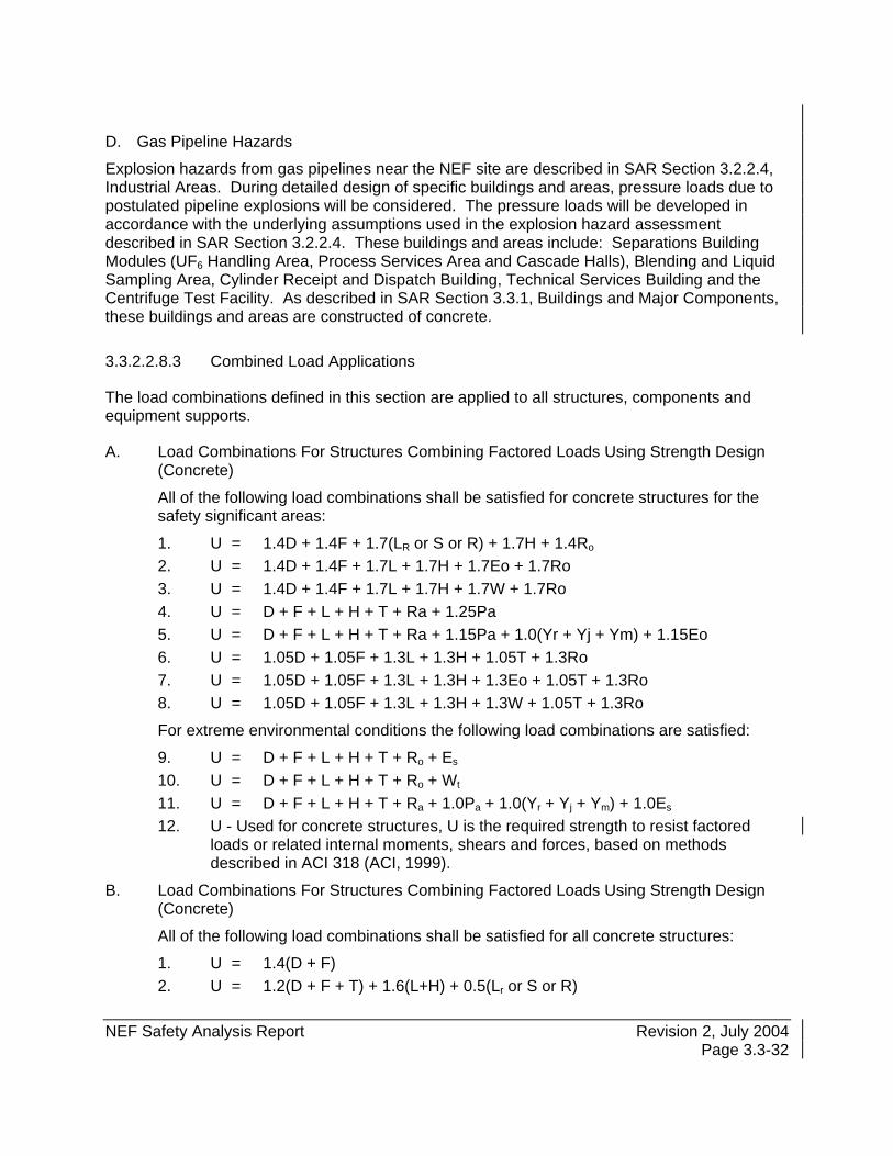
NEF Safety Analysis Report Revision 2, July 2004 Page 3.3-32
D. Gas Pipeline Hazards
Explosion hazards from gas pipelines near the NEF site are described in SAR Section 3.2.2.4, Industrial Areas. During detailed design of specific buildings and areas, pressure loads due to postulated pipeline explosions will be considered. The pressure loads will be developed in accordance with the underlying assumptions used in the explosion hazard assessment described in SAR Section 3.2.2.4. These buildings and areas include: Separations Building Modules (UF6 Handling Area, Process Services Area and Cascade Halls), Blending and Liquid Sampling Area, Cylinder Receipt and Dispatch Building, Technical Services Building and the Centrifuge Test Facility. As described in SAR Section 3.3.1, Buildings and Major Components, these buildings and areas are constructed of concrete.
3.3.2.2.8.3 Combined Load Applications
The load combinations defined in this section are applied to all structures, components and equipment supports.
A. Load Combinations For Structures Combining Factored Loads Using Strength Design (Concrete)
All of the following load combinations shall be satisfied for concrete structures for the safety significant areas:
1. U = 1.4D + 1.4F + 1.7(LR or S or R) + 1.7H + 1.4Ro 2. U = 1.4D + 1.4F + 1.7L + 1.7H + 1.7Eo + 1.7Ro 3. U = 1.4D + 1.4F + 1.7L + 1.7H + 1.7W + 1.7Ro 4. U = D + F + L + H + T + Ra + 1.25Pa 5. U = D + F + L + H + T + Ra + 1.15Pa + 1.0(Yr + Yj + Ym) + 1.15Eo 6. U = 1.05D + 1.05F + 1.3L + 1.3H + 1.05T + 1.3Ro 7. U = 1.05D + 1.05F + 1.3L + 1.3H + 1.3Eo + 1.05T + 1.3Ro 8. U = 1.05D + 1.05F + 1.3L + 1.3H + 1.3W + 1.05T + 1.3Ro
For extreme environmental conditions the following load combinations are satisfied:
9. U = D + F + L + H + T + Ro + Es 10. U = D + F + L + H + T + Ro + Wt 11. U = D + F + L + H + T + Ra + 1.0Pa + 1.0(Yr + Yj + Ym) + 1.0Es 12. U - Used for concrete structures, U is the required strength to resist factored
loads or related internal moments, shears and forces, based on methods described in ACI 318 (ACI, 1999).
B. Load Combinations For Structures Combining Factored Loads Using Strength Design (Concrete)
All of the following load combinations shall be satisfied for all concrete structures:
1. U = 1.4(D + F) 2. U = 1.2(D + F + T) + 1.6(L+H) + 0.5(Lr or S or R)
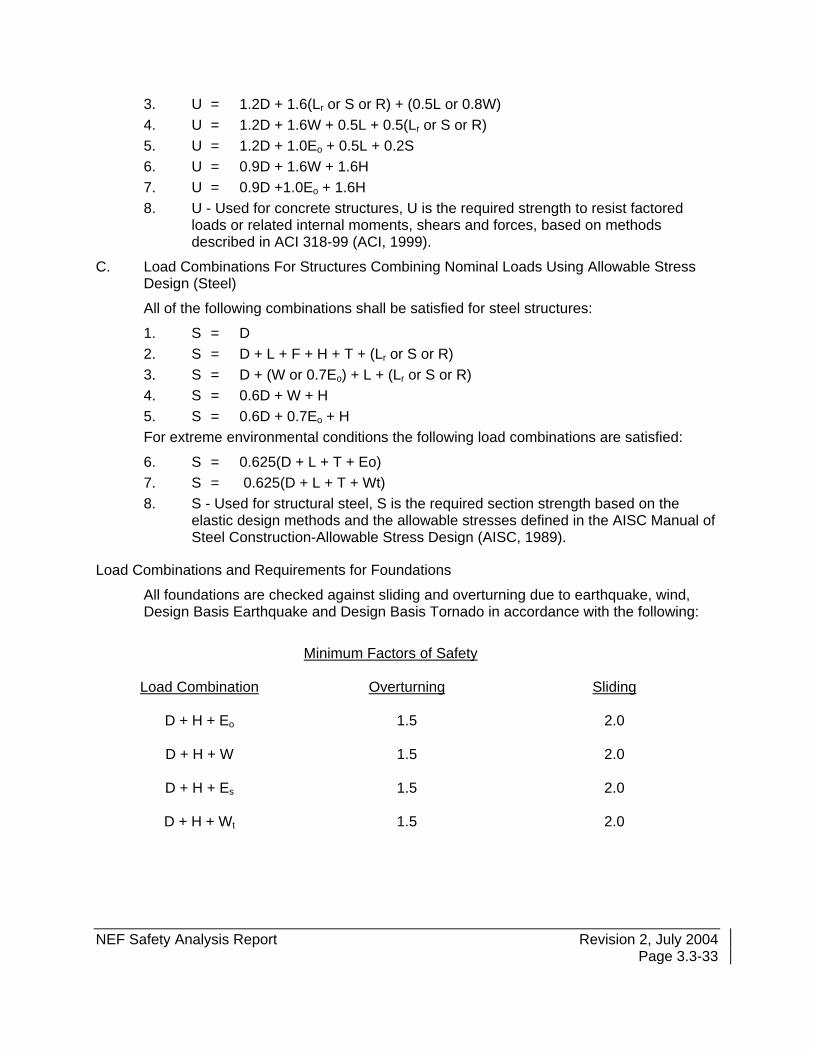
NEF Safety Analysis Report Revision 2, July 2004 Page 3.3-33
3. U = 1.2D + 1.6(Lr or S or R) + (0.5L or 0.8W) 4. U = 1.2D + 1.6W + 0.5L + 0.5(Lr or S or R) 5. U = 1.2D + 1.0Eo + 0.5L + 0.2S 6. U = 0.9D + 1.6W + 1.6H 7. U = 0.9D +1.0Eo + 1.6H 8. U - Used for concrete structures, U is the required strength to resist factored
loads or related internal moments, shears and forces, based on methods described in ACI 318-99 (ACI, 1999).
C. Load Combinations For Structures Combining Nominal Loads Using Allowable Stress Design (Steel)
All of the following combinations shall be satisfied for steel structures:
1. S = D 2. S = D + L + F + H + T + (Lr or S or R) 3. S = D + (W or 0.7Eo) + L + (Lr or S or R) 4. S = 0.6D + W + H 5. S = 0.6D + 0.7Eo + H For extreme environmental conditions the following load combinations are satisfied:
6. S = 0.625(D + L + T + Eo) 7. S = 0.625(D + L + T + Wt) 8. S - Used for structural steel, S is the required section strength based on the
elastic design methods and the allowable stresses defined in the AISC Manual of Steel Construction-Allowable Stress Design (AISC, 1989).
Load Combinations and Requirements for Foundations
All foundations are checked against sliding and overturning due to earthquake, wind, Design Basis Earthquake and Design Basis Tornado in accordance with the following:
Minimum Factors of Safety
Load Combination Overturning Sliding
D + H + Eo 1.5 2.0
D + H + W 1.5 2.0
D + H + Es 1.5 2.0
D + H + Wt 1.5 2.0
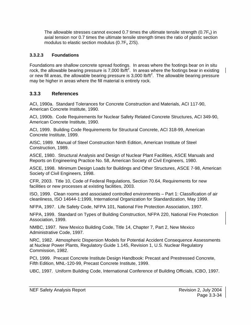
NEF Safety Analysis Report Revision 2, July 2004 Page 3.3-34
The allowable stresses cannot exceed 0.7 times the ultimate tensile strength (0.7Fu) in axial tension nor 0.7 times the ultimate tensile strength times the ratio of plastic section modulus to elastic section modulus (0.7Fu Z/S).
3.3.2.3 Foundations
Foundations are shallow concrete spread footings. In areas where the footings bear on in situ rock, the allowable bearing pressure is 7,000 lb/ft2. In areas where the footings bear in existing or new fill areas, the allowable bearing pressure is 3,000 lb/ft2. The allowable bearing pressure may be higher in areas where the fill material is entirely rock.
3.3.3 References
ACI, 1990a. Standard Tolerances for Concrete Construction and Materials, ACI 117-90, American Concrete Institute, 1990.
ACI, 1990b. Code Requirements for Nuclear Safety Related Concrete Structures, ACI 349-90, American Concrete Institute, 1990.
ACI, 1999. Building Code Requirements for Structural Concrete, ACI 318-99, American Concrete Institute, 1999.
AISC, 1989. Manual of Steel Construction Ninth Edition, American Institute of Steel Construction, 1989.
ASCE, 1980. Structural Analysis and Design of Nuclear Plant Facilities, ASCE Manuals and Reports on Engineering Practice No. 58, American Society of Civil Engineers, 1980.
ASCE, 1998. Minimum Design Loads for Buildings and Other Structures, ASCE 7-98, American Society of Civil Engineers, 1998.
CFR, 2003. Title 10, Code of Federal Regulations, Section 70.64, Requirements for new facilities or new processes at existing facilities, 2003.
ISO, 1999. Clean rooms and associated controlled environments – Part 1: Classification of air cleanliness, ISO 14644-1:1999, International Organization for Standardization, May 1999.
NFPA, 1997. Life Safety Code, NFPA 101, National Fire Protection Association, 1997.
NFPA, 1999. Standard on Types of Building Construction, NFPA 220, National Fire Protection Association, 1999.
NMBC, 1997. New Mexico Building Code, Title 14, Chapter 7, Part 2, New Mexico Administrative Code, 1997.
NRC, 1982. Atmospheric Dispersion Models for Potential Accident Consequence Assessments at Nuclear Power Plants, Regulatory Guide 1.145, Revision 1, U.S. Nuclear Regulatory Commission, 1982.
PCI, 1999. Precast Concrete Institute Design Handbook: Precast and Prestressed Concrete, Fifth Edition, MNL-120-99, Precast Concrete Institute, 1999.
UBC, 1997. Uniform Building Code, International Conference of Building Officials, ICBO, 1997.
NEF Safety Analysis Report December 2003
TABLES
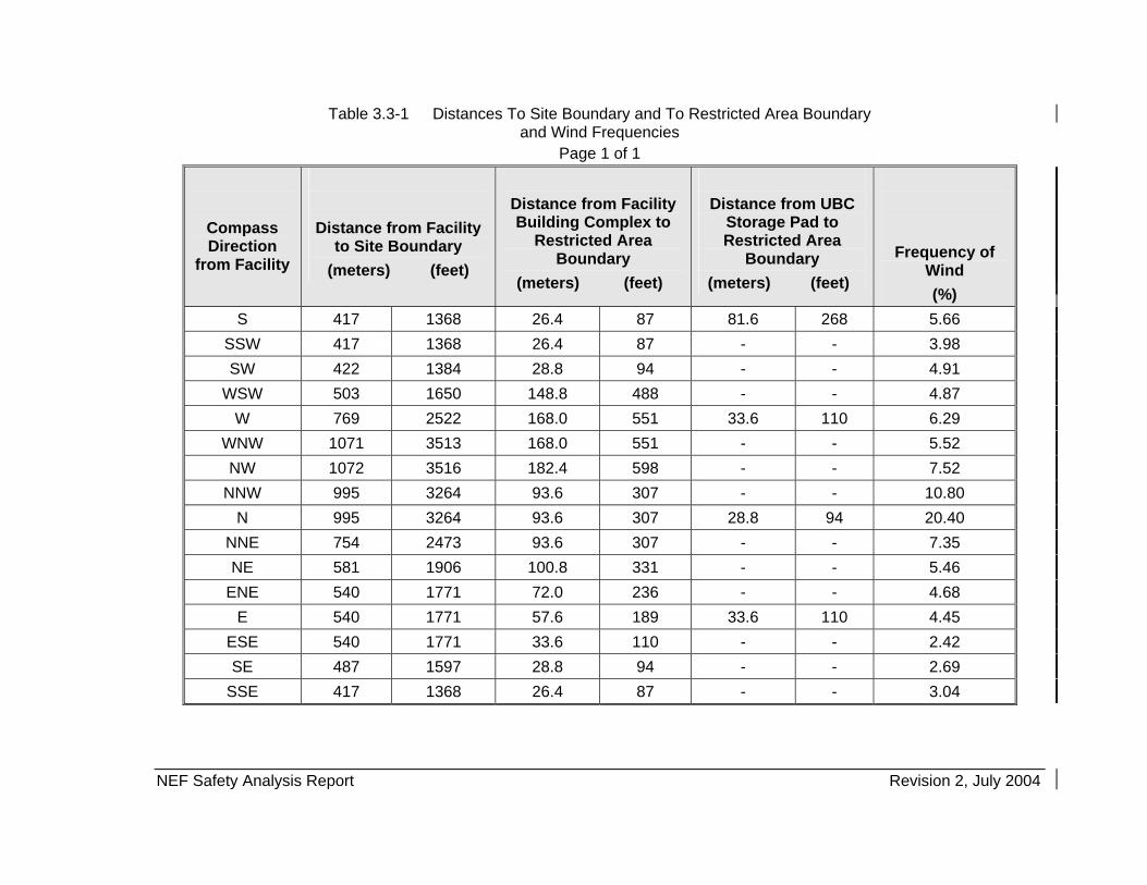
NEF Safety Analysis Report Revision 2, July 2004
Table 3.3-1 Distances To Site Boundary and To Restricted Area Boundary and Wind Frequencies
Page 1 of 1
Compass Direction
from Facility
Distance from Facility to Site Boundary
(meters) (feet)
Distance from Facility Building Complex to
Restricted Area Boundary
(meters) (feet)
Distance from UBC
Storage Pad to Restricted Area
Boundary (meters) (feet)
Frequency of Wind (%)
S 417 1368 26.4 87 81.6 268 5.66 SSW 417 1368 26.4 87 - - 3.98 SW 422 1384 28.8 94 - - 4.91
WSW 503 1650 148.8 488 - - 4.87 W 769 2522 168.0 551 33.6 110 6.29
WNW 1071 3513 168.0 551 - - 5.52 NW 1072 3516 182.4 598 - - 7.52
NNW 995 3264 93.6 307 - - 10.80 N 995 3264 93.6 307 28.8 94 20.40
NNE 754 2473 93.6 307 - - 7.35 NE 581 1906 100.8 331 - - 5.46
ENE 540 1771 72.0 236 - - 4.68 E 540 1771 57.6 189 33.6 110 4.45
ESE 540 1771 33.6 110 - - 2.42 SE 487 1597 28.8 94 - - 2.69
SSE 417 1368 26.4 87 - - 3.04

NEF Safety Analysis Report December 2003
FIGURES
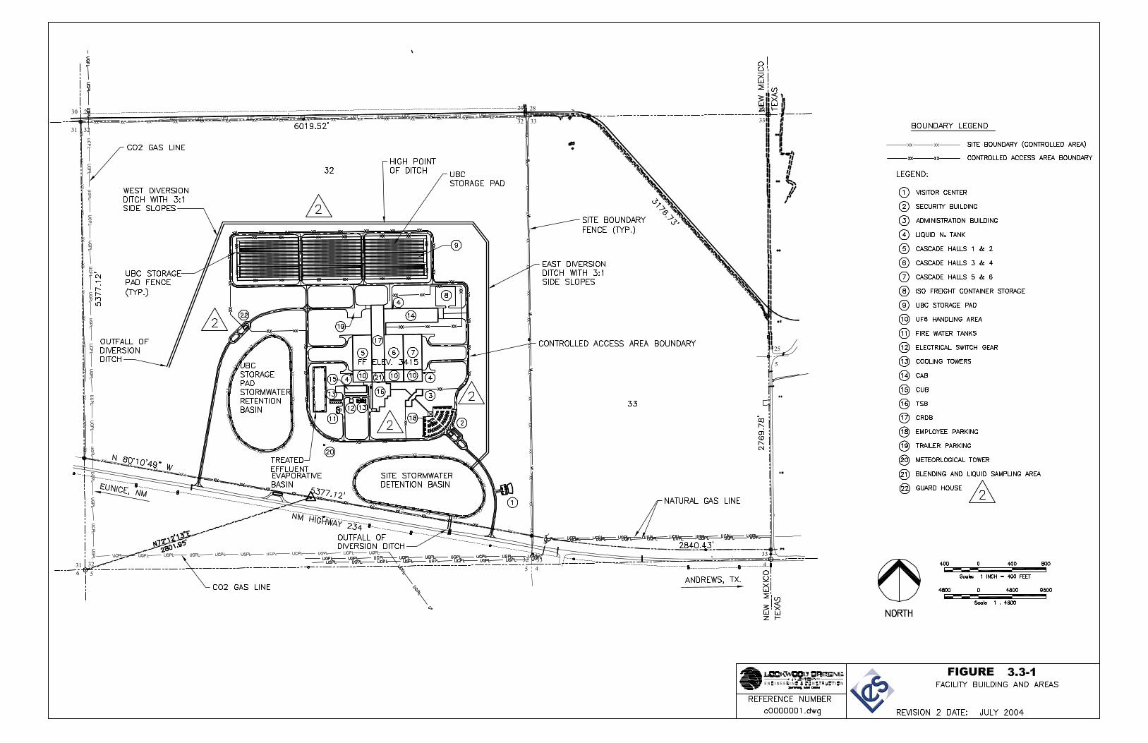
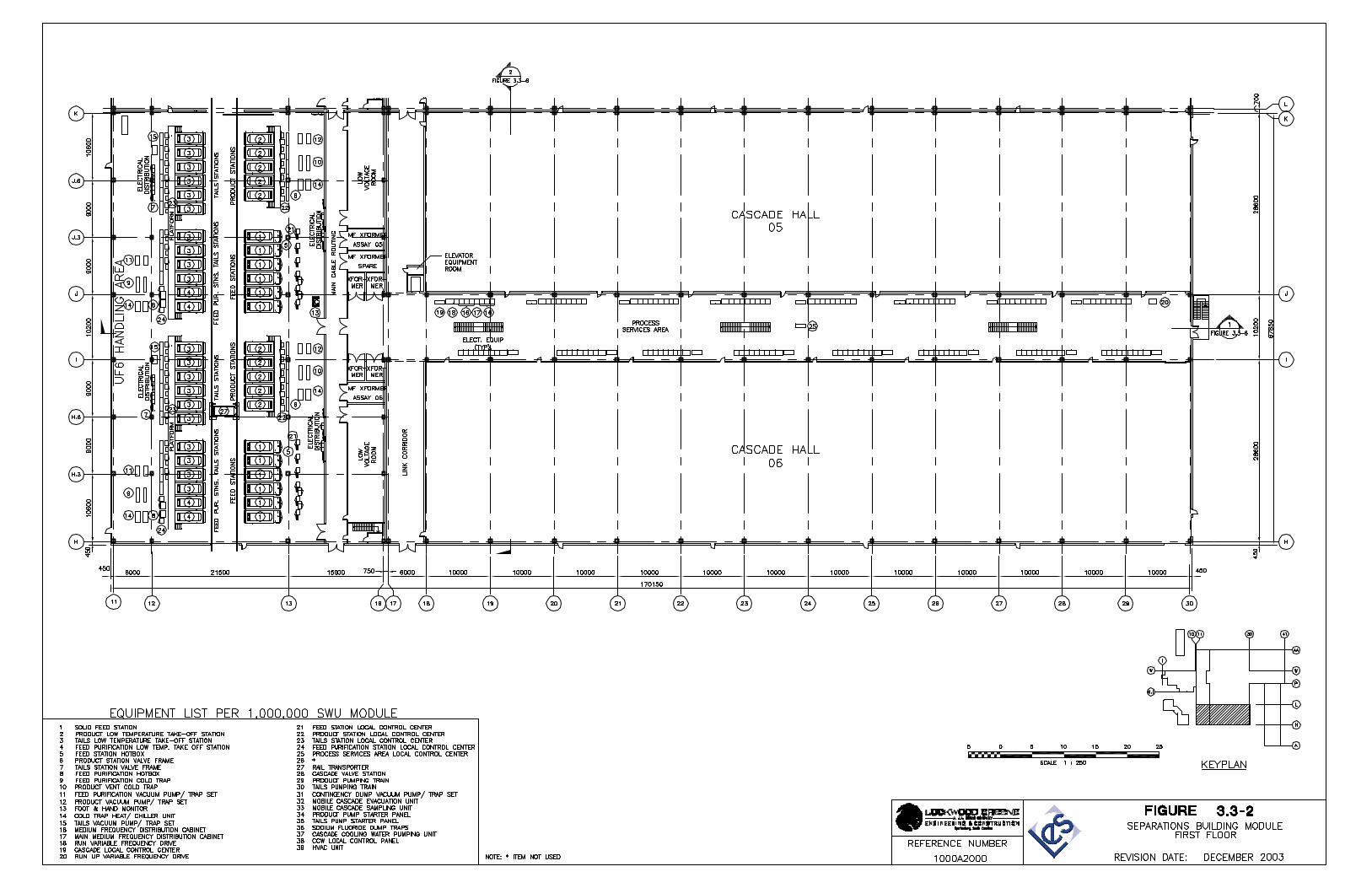
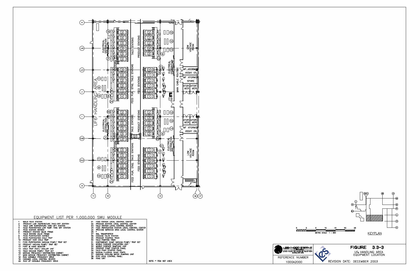
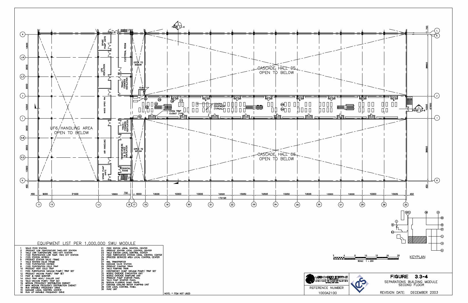
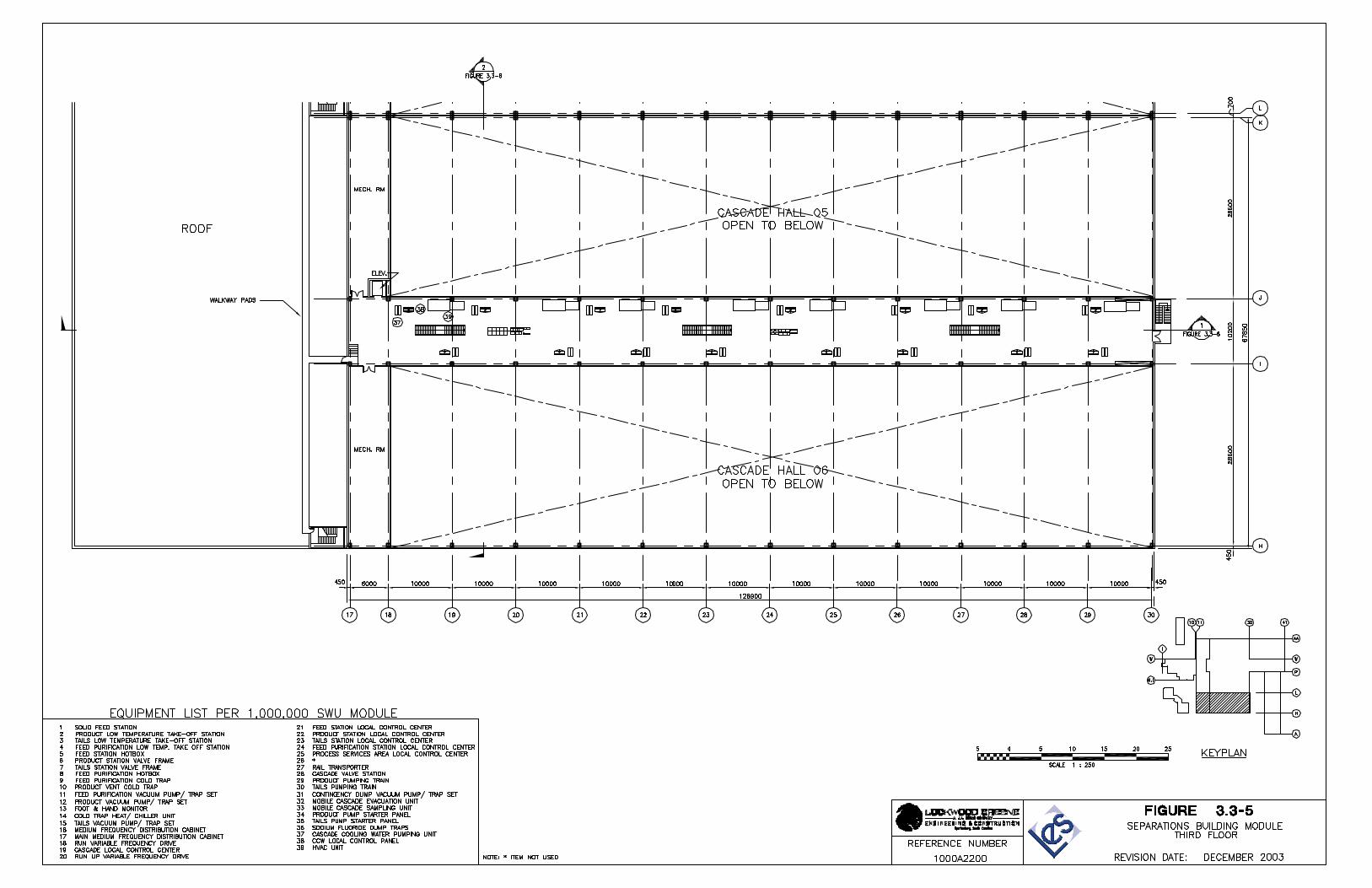
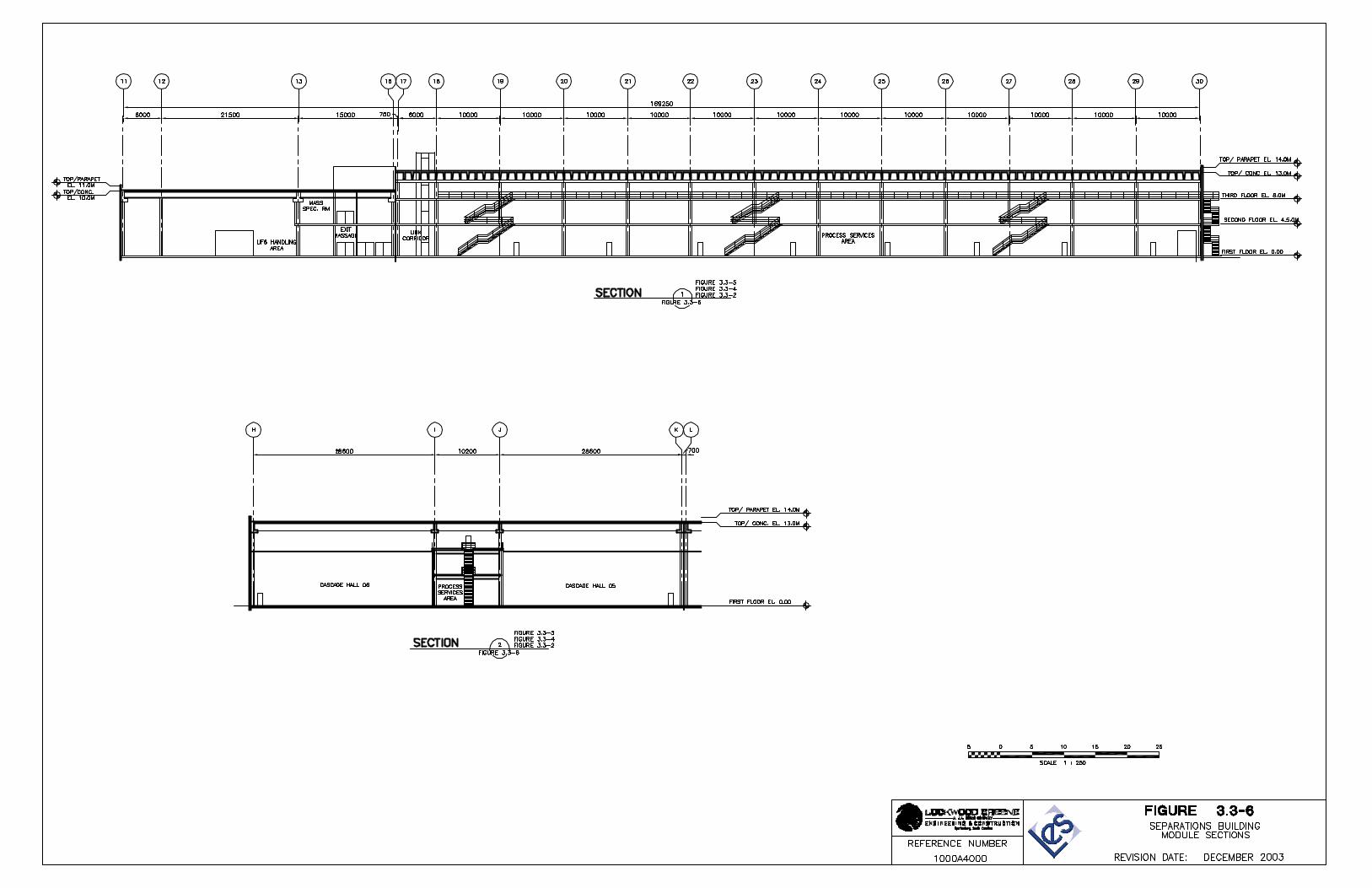
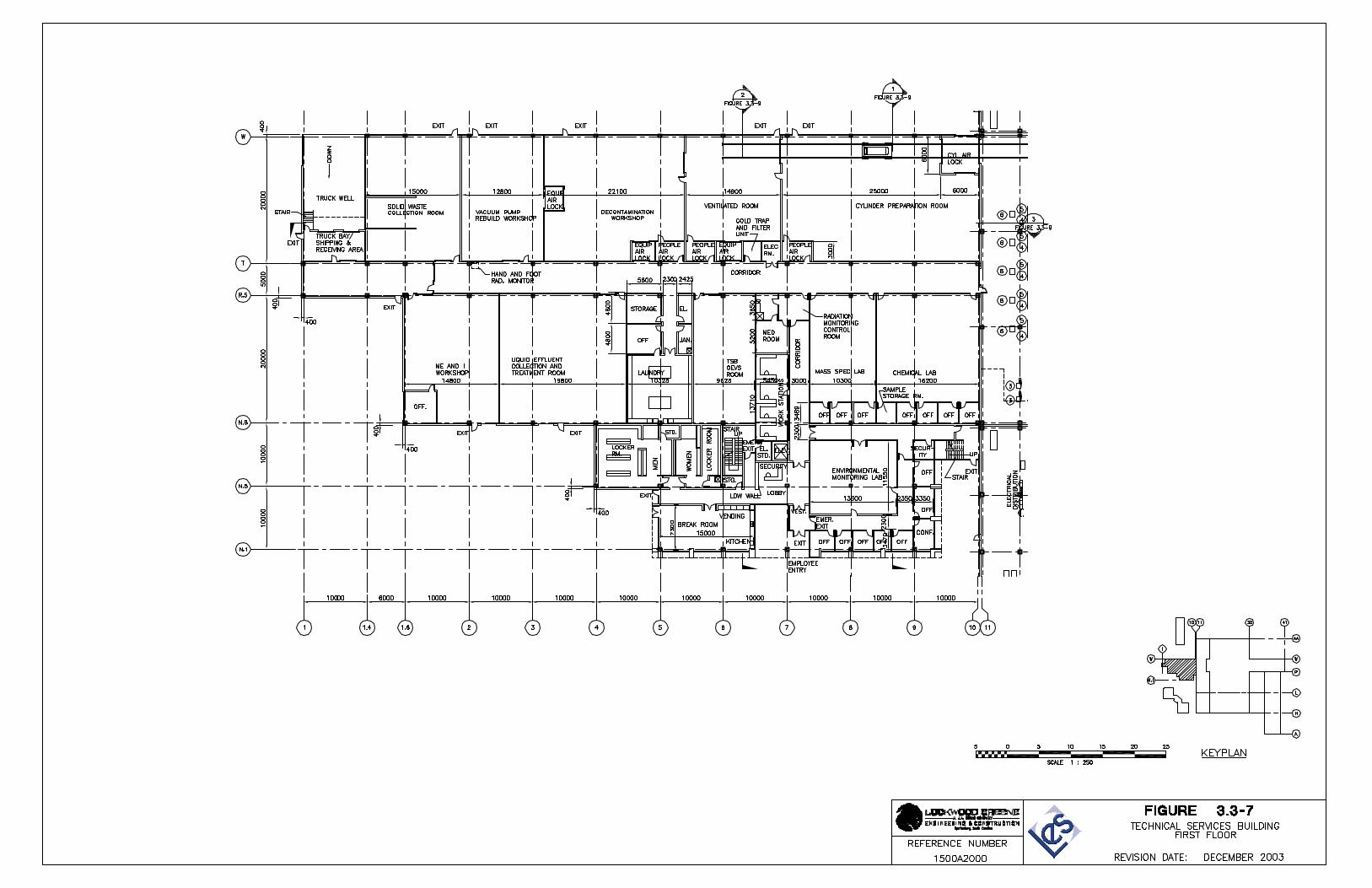
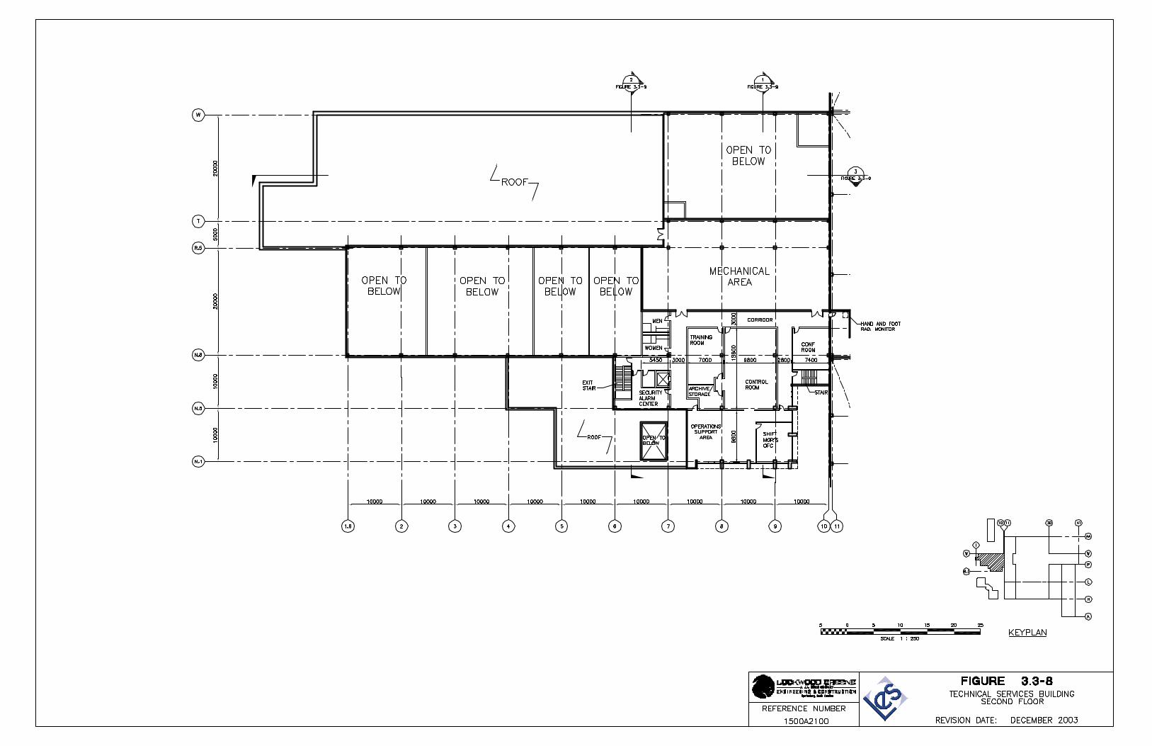
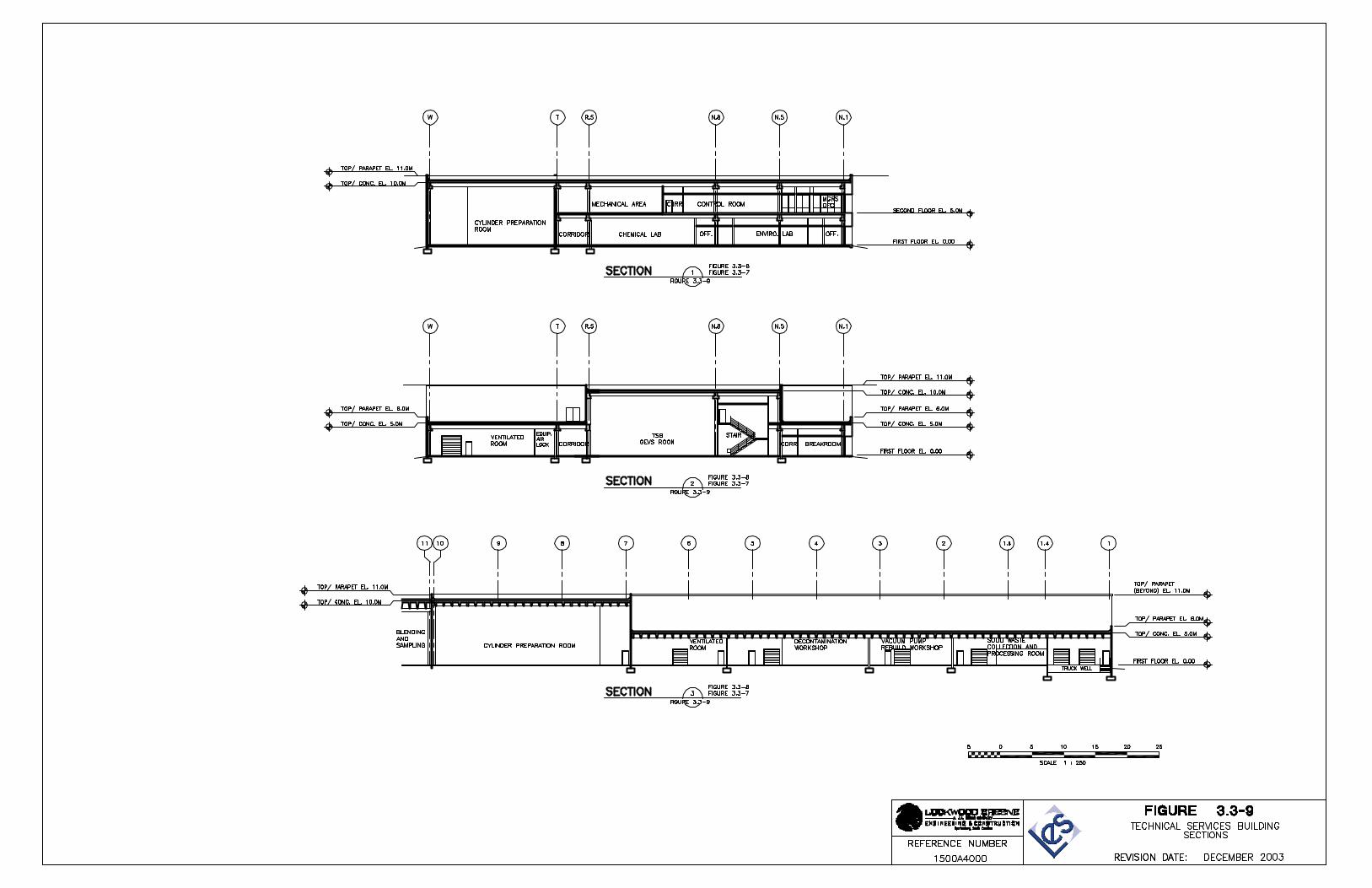
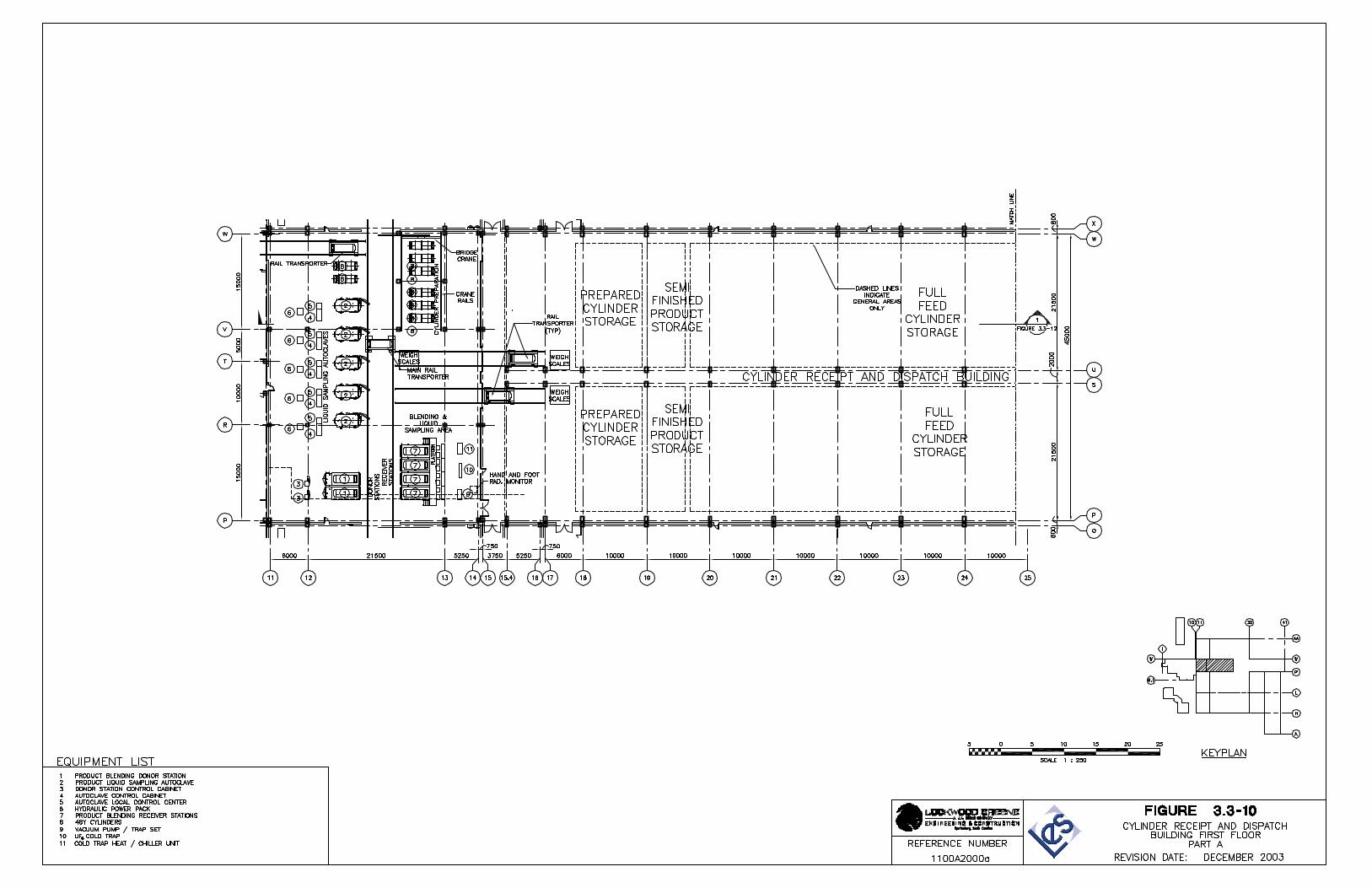
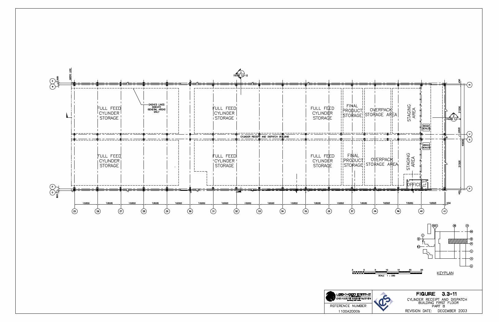
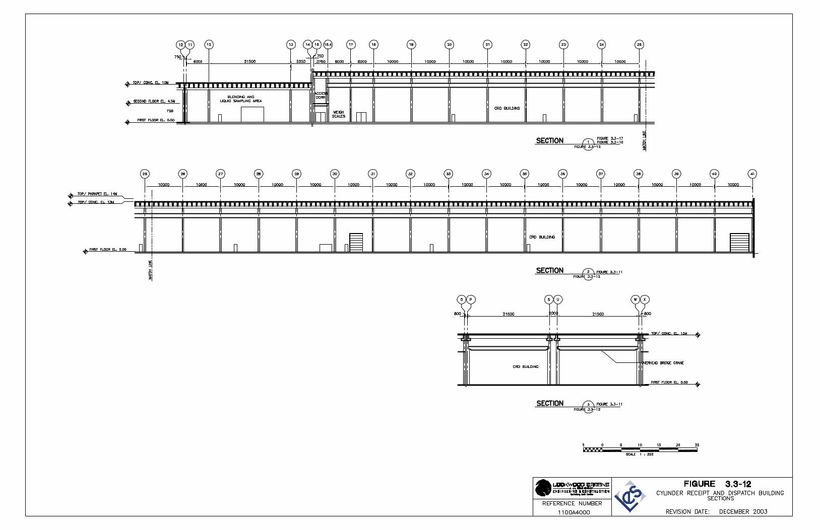
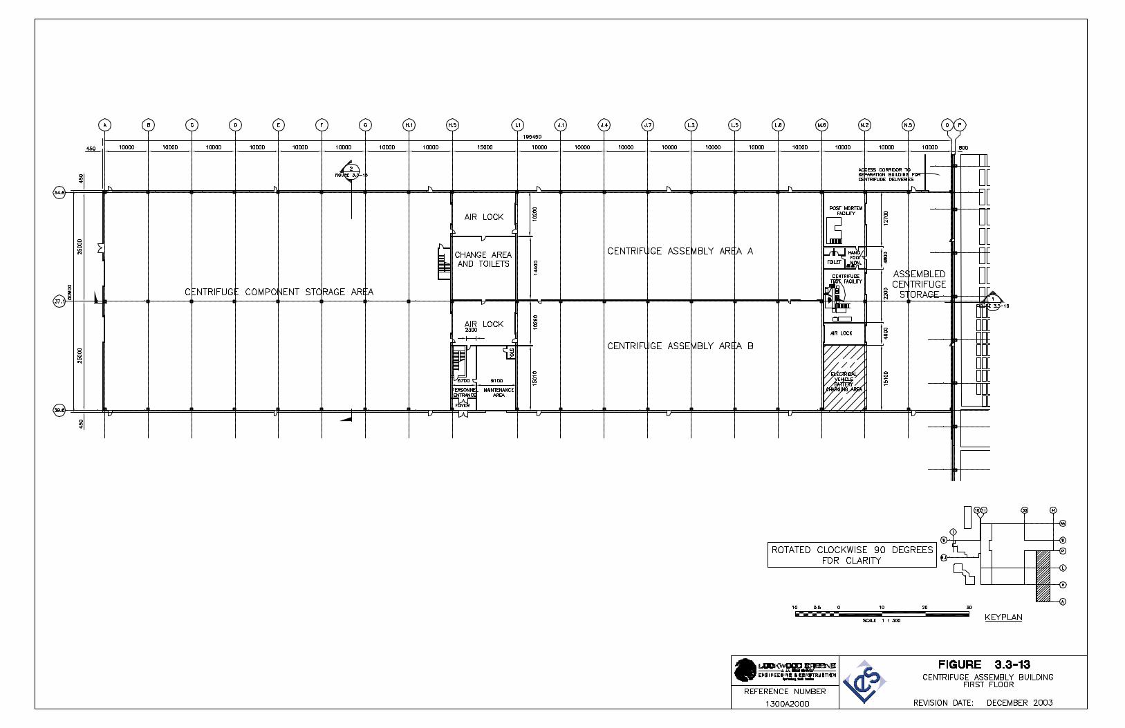
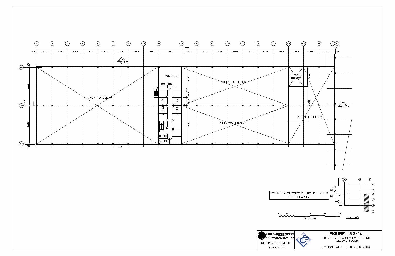
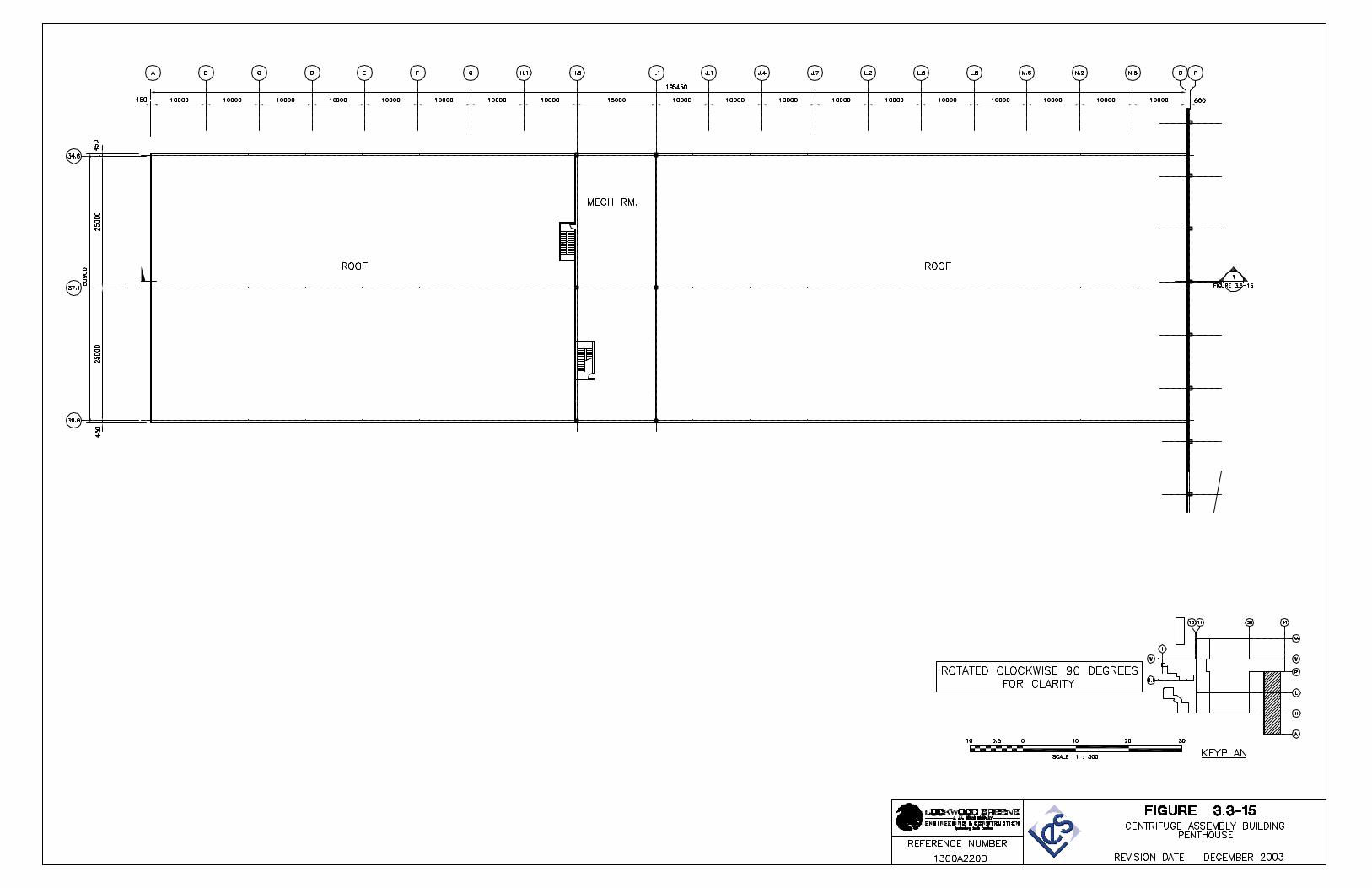
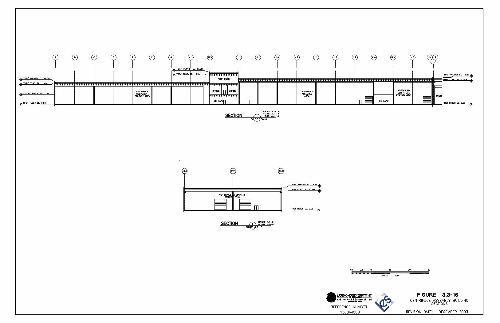
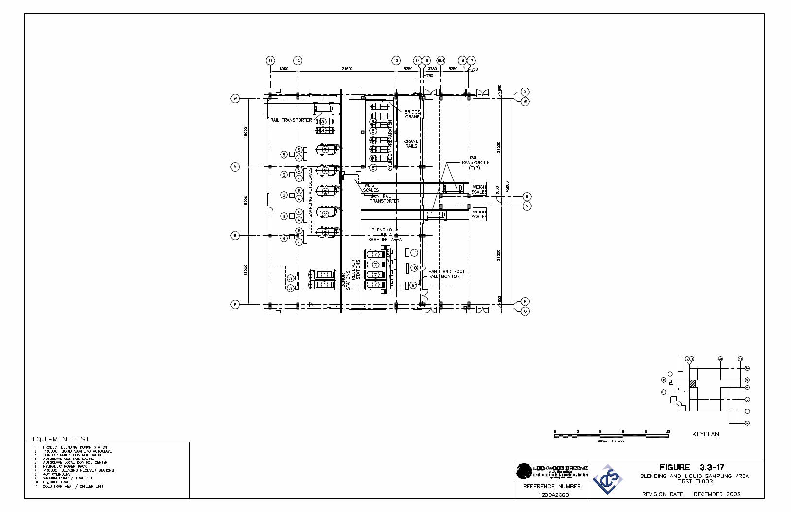
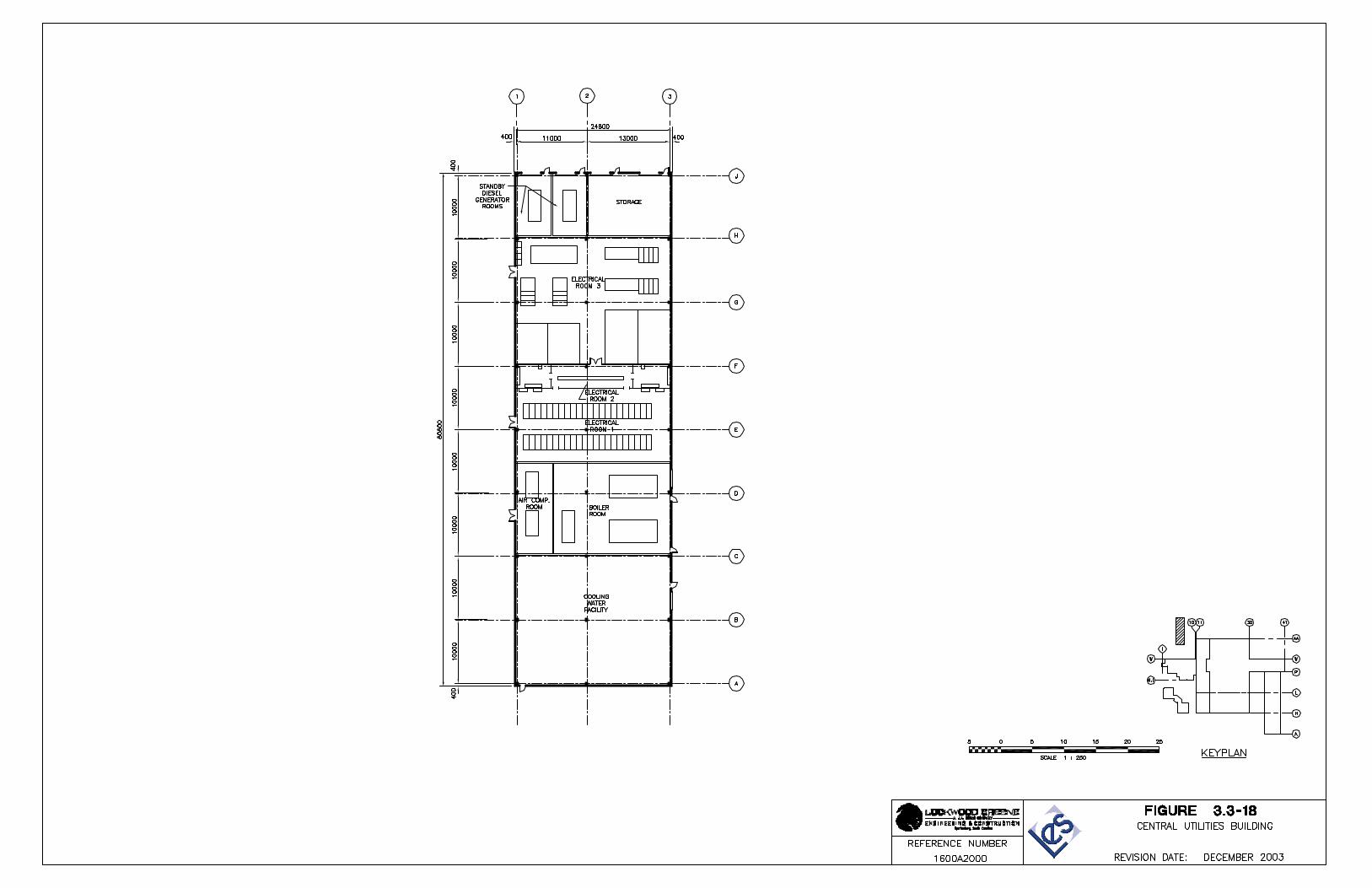
NEF Safety Analysis Report Revision 2, July 2004 Page 3.4-i
TABLE OF CONTENTS Page
3.4 PROCESS DESCRIPTIONS..................................................................................3.4-1 3.4.1 Overview Of Gas Centrifuge Enrichment Process......................................3.4-3
3.4.1.1 UF6 Feed System ........................................................................3.4-3 3.4.1.2 Cascade System .........................................................................3.4-4 3.4.1.3 Product Take-off System.............................................................3.4-4 3.4.1.4 Tails Take-off System..................................................................3.4-4 3.4.1.5 Product Blending System ............................................................3.4-5 3.4.1.6 Product Liquid Sampling System.................................................3.4-5
3.4.2 UF6 Feed System........................................................................................3.4-6 3.4.2.1 Functional Description.................................................................3.4-6 3.4.2.2 Major Components ......................................................................3.4-7 3.4.2.3 Design Description ......................................................................3.4-9 3.4.2.4 Interfaces...................................................................................3.4-10 3.4.2.5 Design and Safety Features......................................................3.4-10 3.4.2.6 Operating Limits ........................................................................3.4-11 3.4.2.7 Instrumentation..........................................................................3.4-11
3.4.3 Cascade System.......................................................................................3.4-14 3.4.3.1 Functional Description...............................................................3.4-15 3.4.3.2 Major Components ....................................................................3.4-15 3.4.3.3 Design Description ....................................................................3.4-16 3.4.3.4 Interfaces...................................................................................3.4-16 3.4.3.5 Design and Safety Features......................................................3.4-17 3.4.3.6 Operating Limits ........................................................................3.4-17 3.4.3.7 Instrumentation..........................................................................3.4-17
3.4.4 Product Take-off System ..........................................................................3.4-18 3.4.4.1 Functional Description...............................................................3.4-19 3.4.4.2 Major Components ....................................................................3.4-19 3.4.4.3 Design Description ....................................................................3.4-21 3.4.4.4 Interfaces...................................................................................3.4-22 3.4.4.5 Design and Safety Features......................................................3.4-22 3.4.4.6 Operating Limits ........................................................................3.4-23 3.4.4.7 Instrumentation..........................................................................3.4-23
3.4.5 Tails Take-off System...............................................................................3.4-26 3.4.5.1 Functional Description...............................................................3.4-26 3.4.5.2 Major Components ....................................................................3.4-27 3.4.5.3 Design Description ....................................................................3.4-28 3.4.5.4 Interfaces...................................................................................3.4-29 3.4.5.5 Design and Safety Features......................................................3.4-29 3.4.5.6 Operating Limits ........................................................................3.4-30 3.4.5.7 Instrumentation..........................................................................3.4-30
3.4.6 Product Blending System .........................................................................3.4-32 3.4.6.1 Functional Description...............................................................3.4-32 3.4.6.2 Major Components ....................................................................3.4-33 3.4.6.3 Design Description ....................................................................3.4-35 3.4.6.4 Interfaces...................................................................................3.4-36
NEF Safety Analysis Report Revision 2, July 2004 Page 3.4-ii
TABLE OF CONTENTS
Page
3.4.6.5 Design and Safety Features......................................................3.4-36 3.4.6.6 Operating Limits ........................................................................3.4-37 3.4.6.7 Instrumentation..........................................................................3.4-37
3.4.7 Product Liquid Sampling System..............................................................3.4-39 3.4.7.1 Functional Description...............................................................3.4-40 3.4.7.2 Major Components ....................................................................3.4-40 3.4.7.3 Design Description ....................................................................3.4-42 3.4.7.4 Interfaces...................................................................................3.4-43 3.4.7.5 Design and Safety Features......................................................3.4-44 3.4.7.6 Operating Limits ........................................................................3.4-45 3.4.7.7 Instrumentation..........................................................................3.4-45
3.4.8 Contingency Dump System ......................................................................3.4-46 3.4.8.1 Functional Description...............................................................3.4-47 3.4.8.2 Major Components ....................................................................3.4-47 3.4.8.3 Design Description ....................................................................3.4-49 3.4.8.4 Interfaces...................................................................................3.4-49 3.4.8.5 Design and Safety Features......................................................3.4-49 3.4.8.6 Operating Limits ........................................................................3.4-50 3.4.8.7 Instrumentation..........................................................................3.4-50
3.4.9 Gaseous Effluent Vent Systems ...............................................................3.4-52 3.4.9.1 Separations Building Gaseous Effluent Vent System................3.4-52 3.4.9.2 Technical Services Building GEVS............................................3.4-56
3.4.10 Centrifuge Test and Centrifuge Post Mortem Processes .........................3.4-60 3.4.10.1 Centrifuge Test Facility..............................................................3.4-60 3.4.10.2 Centrifuge Post Mortem Facility ................................................3.4-64 3.4.10.3 Centrifuge Test and Post Mortem Facilities Exhaust Filtration
System .....................................................................................3.4-66 3.4.11 Material Handling Processes ....................................................................3.4-68
3.4.11.1 Cylinder Receipt and Shipping ..................................................3.4-69 3.4.11.2 Cylinder Transport within the Facility.........................................3.4-73 3.4.11.3 UBC Storage Pad......................................................................3.4-74
3.4.12 References ...............................................................................................3.4-75
NEF Safety Analysis Report Revision 1, February 2004 Page 3.4-iii
LIST OF TABLES
Table 3.4-1 UF6 Feed System Design Basis Table 3.4-2 UF6 Feed System Codes and Standards Table 3.4-3 Cascade System Codes and Standards Table 3.4-4 Product Take-off System Design Basis Table 3.4-5 Product Take-off System Codes and Standards Table 3.4-6 Tails Take-off System Design Basis Table 3.4-7 Tails Take-off System Codes and Standards Table 3.4-8 Product Blending System Design Basis Table 3.4-9 Product Blending System Codes and Standards Table 3.4-10 Product Liquid Sampling System Design Basis Table 3.4-11 Product Liquid Sampling System Codes and Standards Table 3.4-12 Contingency Dump System Design Basis Table 3.4-13 Contingency Dump System Codes and Standards Table 3.4-14 Gaseous Effluent Vent System Codes and Standards Table 3.4-15 Gaseous Effluent Vent System Design Bases (Separations Building) Table 3.4-16 Gaseous Effluent Vent System Design Bases (Technical Services Building) Table 3.4-17 Functional Requirements for Centrifuge Test and Post Mortem Facilities Table 3.4-18 Utility Requirements for Centrifuge Test and Post Mortem Facilities Table 3.4-19 UF6 Feed Cylinder Delivery and Storage Requirements Table 3.4-20 Crane Movement Requirements Table 3.4-21 UBC Storage System Requirements
NEF Safety Analysis Report Revision 1, February 2004 Page 3.4-iv
LIST OF FIGURES
Figure 3.4-1 Pictorial Representation of the Enrichment Process Figure 3.4-2 Process Flow Diagram UF6 Feed System Figure 3.4-3 Solid Feed Station Equipment Drawing Figure 3.4-4 Low Temperature Take-off Station Equipment Drawing Figure 3.4-5 UF6 Cold Trap Equipment Drawing Figure 3.4-6 Chemical Trap Equipment Drawing Figure 3.4-7 The Enrichment Process Figure 3.4-8 Cascade Process Scheme Equipment Drawing Figure 3.4-9 Principle of a Gas Centrifuge Figure 3.4-10 Process Flow Diagram Product Take-off System Figure 3.4-11 Process Flow Diagram Tails Take-off System Figure 3.4-12 Process Flow Diagram Product Blending System Figure 3.4-13 Process Flow Diagram Product Liquid Sampling System Figure 3.4-14 Liquid Sampling Autoclave Equipment Drawing Figure 3.4-15 Process Flow Diagram Contingency Dump System Figure 3.4-16 NaF Trap Equipment Drawing Figure 3.4-17 Process Flow Diagram, Gaseous Effluent Vent System Separations Building,
Sheet 1 of 2 Figure 3.4-17 Process Flow Diagram, Gaseous Effluent Vent System Separations Building
Sheet 2 of 2 Figure 3.4-18 Process Flow Diagram, Gaseous Effluent Vent System Technical Services
Building Sheet 1 of 2 Figure 3.4-18 P&ID, Gaseous Effluent Vent System Technical Services Building Sheet 2 of 2 Figure 3.4-19 Process Flow Diagram Centrifuge Test and Post Mortem Facilities Exhaust
Filtration System Figure 3.4-20 Rail Transporter Equipment Drawing
NEF Safety Analysis Report Revision 2, July 2004 Page 3.4-1
3.4 PROCESS DESCRIPTIONS
This section provides a description of the enrichment processes and systems analyzed as part of the integrated safety assessment. A brief overview of the entire enrichment process is provided followed by a detailed description of each process system. The section provides design, operational, and process flow information to support the hazard and accident analysis, as well as to assist in understanding the overall design and function of the National Enrichment Facility (NEF).
The enrichment systems are comprised of the following four major systems:
• UF6 Feed System
• Cascade System
• Product Take-off System
• Tails Take-off System.
The above systems are used only for the enrichment process. In addition to the four primary systems listed above, there are several major support systems discussed in this section:
• Product Blending System
• Product Liquid Sampling System
• Contingency Dump System.
Finally, the following processes and systems are discussed based on their supporting relationship to the enrichment process and the handling of UF6:
• Gaseous Effluent Vent Systems (GEVSs)
• Centrifuge Test Facility and Centrifuge Post Mortem Facility
• Material Handling.
Each of the sections that discuss the 10 processes identified above are generally organized to present the following information:
• Functional Description
• Major Components
• Design Description
• Interfaces
• Design and Safety Features
• Operating Limits
• Instrumentation
Items relied on for safety associated with the processes and systems identified above are listed in Section 3.8, Items Relied On For Safety (IROFS).
NEF Safety Analysis Report December 2003 Page 3.4-2
In the following sections, the design process parameter values are specified with a datum of standard atmospheric pressure at sea level. These values will be finalized to reflect the site-specific NEF elevation during the design phase and the Safety Analysis Report will be revised accordingly.
The enrichment process at the NEF is basically the same process described in the Safety Analysis Report for the Claiborne Enrichment Center (LES, 1993). The Nuclear Regulatory Commission (NRC) documented its review of the Claiborne Enrichment Center license application and concluded that Louisiana Energy Services’ (LES) application provided an adequate basis for safety review of facility operations and that construction and operation of the Claiborne Enrichment Center would not pose an undue risk to public health and safety (NRC, 1994). The design of the NEF incorporates the latest design and safety features from the Urenco enrichment facilities currently operating in Europe.
The major process design differences between the Claiborne Enrichment Center and the NEF are summarized below. Additional details are provided at the beginning of each subsection on how NEF compares to the Claiborne Enrichment Center processes and systems.
The primary difference between the Claiborne Enrichment Center and the NEF is the increase in enrichment capacity. The NEF is designed for 3.0 million separative work units (SWU) per year. The Claiborne Enrichment Center was designed for 1.5 million SWU per year.
The Claiborne Enrichment Center used a feed system that operated above atmospheric pressure. During purification or when feeding to the centrifuges, the UF6 in the cylinders was in a liquid phase. Autoclaves were used to heat the feed cylinders and to contain any UF6 in the event there were any leaks in the feed cylinder or piping. The feed purification station used chilled water at 3.9°C (39.0°F) supplied from a common system to chill the purification cylinder.
The NEF feed and feed purification systems do not use UF6 in the liquid phase. Also, the operating pressure in the feed and purification systems stays considerably below atmospheric pressure. The UF6 feed is changed from the solid phase to the gaseous phase without going through the liquid phase. This is achieved because the feed system temperature is maintained below the triple point. The Solid Feed Stations used in the UF6 Feed System are not constructed as autoclaves. There is no need for secondary confinement barriers due to the UF6 not being in the liquid phase and the subatmospheric pressure of the system. The Feed Purification Low Temperature Take-off Station is cooled by air that is chilled by individual electrically operated chiller units (not water). The purification stations operate at –25°C (-13°F), which is considerably colder than the Claiborne Enrichment Center design. Not using liquid UF6 and operating at a subatmospheric pressure are major safety enhancements from the Claiborne Enrichment Center design.
The Claiborne Enrichment Center used cooled air at 10°C (50°F) to chill the product cylinders while they were in the Product Take-off Stations. For the NEF, the Product Take-off Stations are cooled by air that is chilled by individual electrically operated chiller units. The Low Temperature Take-off Stations operate at –25°C (-13°F), which is considerably colder than the previous design. The operating pressure for the Low Temperature Take-off Stations is considerably lower for the NEF.
NEF Safety Analysis Report December 2003 Page 3.4-3
3.4.1 Overview Of Gas Centrifuge Enrichment Process
The function of the NEF is to enrich (increase) the amount of 235U isotope in uranium hexafluoride (UF6) from naturally occurring feed at 0.711 w/o up to a maximum of 5.0 w/o. The enriched UF6 is then used for manufacturing fuel for commercial electricity generating nuclear power plants.
Figure 3.4-1, Pictorial Representation of the Enrichment Process, illustrates the process flow in schematic form. An overview of the enrichment process systems and the enrichment support systems are discussed below. Additional details on each of the enrichment process systems are provided in subsequent sections.
3.4.1.1 UF6 Feed System
The first step in the process is the receipt of the feed cylinders and preparation to feed the UF6 through the enrichment process.
Natural UF6 feed is received at the NEF in Department of Transportation (DOT) 7A, Type A cylinders from a conversion plant. The cylinders are ANSI N14.1 (ANSI, applicable version), 48Y or 48X cylinders. Pressure in the feed cylinders is below atmospheric (vacuum) and the UF6 is in solid form.
The function of the UF6 Feed System is to provide a continuous supply of gaseous UF6 from the feed cylinders to the cascades. The maximum feed flow rate is 187 kg/hr (412 lb/hr) based on a maximum capacity of 545,000 SWU/yr per Cascade Hall.
To begin the enrichment process, a 48-in feed cylinder is placed into a Solid Feed Station. There are six Solid Feed Stations per Cascade Hall. Normally three are online. Each Solid Feed Station consists of an insulated enclosure, heated by electric heaters, into which the cylinder is placed. The cylinder is heated to 53°C (127°F) in the Solid Feed Station. At this temperature and pressure (subatmospheric), the solid UF6 sublimes into a gas. An important safety feature of the feed system is that at no time does the UF6 go into a liquid phase.
The feed purification system is used to remove the light gas components from the UF6 feed material to a specified level prior to admittance to the cascades. This protects the centrifuges against high intake of light gas and enhances cascade efficiency by limiting impurities.
For each Cascade Hall, there are two feed purification Low Temperature Take-off Stations. These stations consist of insulated enclosures that are maintained at –25°C (-13°F) by electrically operated chiller units. 48X or 48Y cylinders are placed into the Low Temperature Take-off Station and chilled to –25°C (-13°F). As the gaseous UF6 enters the cylinder, desublimation into solid UF6 occurs. In addition to the Low Temperature Take-off Station, there are two UF6 Cold Traps which desublime UF6, carbon traps, aluminum oxide (Al2O3) traps, and vacuum pumps, used to transfer residual light gas to the Gaseous Effluent Vent System. The carbon and aluminum oxide traps remove trace UF6 and HF from the gas stream.
After purification, the UF6 gas is then fed through a main header to the cascades, where the enrichment process actually occurs. The pressure in the main header is limited to 65 mbar (26.1 in. H2O) to prevent the gaseous UF6 from desubliming back to a solid at ambient temperature.
NEF Safety Analysis Report December 2003 Page 3.4-4
3.4.1.2 Cascade System
The function of the Cascade System is to receive gaseous UF6 from the UF6 Feed System and enrich the 235U isotope in the UF6 to a maximum of 5 w/o.
Multiple gas centrifuges make up arrays called cascades. The cascades separate gaseous UF6 feed with a natural uranium isotopic concentration into two process flow streams – product and tails. The product stream is the enriched UF6 stream. The tails stream is UF6 that has been depleted of 235U isotope.
3.4.1.3 Product Take-off System
The function of the Product Take-off System is to provide continuous withdrawal of the enriched gaseous UF6 product from the cascades. The maximum product flow rate per Cascade Hall is 18.4 kg/hr (40.6 lb/hr) based on a maximum Cascade Hall capacity of 545,000 SWU/yr.
The product streams leaving the cascades (at each Cascade Hall) are brought together into one common manifold. The product stream is transported via a train of vacuum pumps to Product Low Temperature Take-off Stations. There are five Product Low Temperature Take-off Stations per Cascade Hall. Normally two are on-line when using 30B cylinders. Each Low Temperature Take-off Station consists of an insulated enclosure that is maintained at –25°C (-13°F) by electrically operated chiller units. A 30B or a 48Y cylinder is placed into the Low Temperature Take-off Station and cooled to –25°C (-13°F). The 30B cylinders contain final product to be shipped to the customer. The 48Y cylinders are used internal to the plant for blending purposes. As the enriched gaseous UF6 enters the cylinder, desublimation into solid UF6 occurs.
The entire system operates at subatmospheric pressure.
The Product Take-off System also contains a system to purge and dispose of light gas impurities from the enrichment process. This system consists of product vent UF6 Cold Traps into which UF6 desublimes while leaving the light gas in a gaseous state. The UF6 Cold Trap is followed by product vent vacuum pump/chemical trap sets, each consisting of a carbon trap, an aluminum oxide trap, and a vacuum pump. The carbon trap removes small traces of UF6 and the aluminum oxide trap removes any HF from the gas flow.
There are connections to the Assay Sampling System and the On-line Mass Spectrometer System for product sampling and analysis.
3.4.1.4 Tails Take-off System
The primary function of the Tails Take-off System is to provide continuous withdrawal of the gaseous UF6 tails from the cascades. The maximum tails flow rate is 168 kg/hr (370 lb/hr) based on a maximum Cascade Hall capacity of 545,000 SWU/yr. A secondary function of this system is to provide a means for removal of UF6 from the centrifuge cascades under abnormal conditions.
The tails stream exits each cascade via a primary header, goes through a pumping train, and then to Tails Low Temperature Take-off Stations. There are ten Low Temperature Take-off Stations per Cascade Hall. Under normal operation, seven of the Low Temperature Take-off Stations are in operation receiving tails and three are on standby.
NEF Safety Analysis Report December 2003 Page 3.4-5
Each Low Temperature Take-off Station consists of an insulated enclosure that is maintained at –25°C (-13°F) by electrically operated chiller units. 48Y cylinders are placed into the Low Temperature Take-off Stations and cooled to –25°C (-13°F). As the gaseous depleted UF6 (tails) enters the cylinder, it desublimes into solid UF6.
The entire system operates at subatmospheric pressure.
The Tails Take-off System also has an evacuation pump/chemical trap set, and connections to the Assay Sampling Subsystem and an On-line Mass Spectrometer System for continuous gas sampling.
3.4.1.5 Product Blending System
The primary function of the Product Blending System is to provide means to fill 30B cylinders with UF6 at a specific enrichment of 235U to meet customer requirements. This is accomplished by blending (mixing) UF6 at two different enrichment levels to one specific enrichment level. The system can also be used to transfer product from a 30B or 48Y cylinder to another 30B cylinder without blending.
The Product Blending System is sized for the complete 3,000,000 SWU/year enrichment plant production.
This system consists of Blending Donor Stations (which are similar to the Solid Feed Stations) and Low Temperature Take-off Blending Receiver Stations (which are similar to the Low Temperature Take-off Stations described earlier).
The donor system consists of two Blending Donor Stations. Each station consists of an insulated enclosure (similar to the Solid Feed Station enclosures). Full 30B or 48Y product cylinders at various enrichment levels are placed into the Blending Donor Stations and are heated to sublime the solid UF6 to gas. The sublimed gas from the two Blending Donor Stations is transported to four Blending Receiver Stations. Each Blending Receiver Station consists of an insulated enclosure that is maintained at –25°C (-13°F) by electrically operated chiller units. Empty 30B cylinders are placed into the station and cooled to –25°C (-13°F). As the gaseous UF6 from the Blending Donor Stations enters the cylinder, desublimation into solid UF6 occurs.
There are no vacuum pumps used to transfer product in this system. The system has a vent system similar to the product vent system.
3.4.1.6 Product Liquid Sampling System
The function of the Product Liquid Sampling System is to obtain a representative assay sample from filled product cylinders. The sample is used to validate the exact enrichment level and quality of UF6 in the filled product cylinders, before the cylinders are sent to the fuel processor.
This is the only system in the NEF that changes solid UF6 to liquid UF6.
The main piece of equipment used in this system is the Product Liquid Sampling Autoclave. A filled 30B product cylinder is placed into the autoclave and a manifold (inside the autoclave) with three sample bottles, is connected to the cylinder valve. After closing the autoclave door, the autoclave is heated to 70°C (158°F) via air heated with electric heaters. As the temperature of the UF6 in the cylinder increases, the pressure also increases. When the pressure in the
NEF Safety Analysis Report December 2003 Page 3.4-6
sample manifold reaches approximately +2.5 bar (36.3 psia), the temperature is stabilized. At this point, the UF6 is a liquid. In order to assure that a sample represents the entire contents of the cylinder, it is necessary to homogenize the UF6. The UF6 will homogenize when the UF6 becomes liquid at the high pressure and temperature. Homogenization typically lasts for 16 hours. After the homogenization period, the sampling process is initiated.
After homogenization, with the sample bottle valves closed, the autoclave is tilted via a tilting mechanism to 30 degrees from horizontal. After the sample manifold is filled, the autoclave is lowered to horizontal, and the sample bottle valves are opened and closed in sequence to collect the samples. The autoclave and cylinder is then cooled down and the autoclave is vented and opened for sample bottle removal.
One of the main safety features of the autoclave is that it is designed to provide a secondary confinement barrier in the unlikely event a leak should occur in the UF6 cylinder or connected piping while the UF6 is in liquid form. Numerous controls are designed into the autoclave to mitigate overheating and other conditions that may affect the integrity of the UF6 system.
3.4.2 UF6 Feed System
The NEF UF6 Feed System uses a process similar to the original LES Claiborne Enrichment Center. The primary differences are as follows:
A. Feed Station Operating Conditions.
The Claiborne Enrichment Center used a feed station that operated above atmospheric pressure. UF6 in the feed cylinder was maintained in the liquid phase. Normal UF6 pressure in the feed cylinder was above atmospheric, at 1.8 bar (26.1 psia). Normal station heating temperature was up to 110°C (230°F). The Claiborne Enrichment Center used a sealed autoclave for secondary containment of the feed cylinder to prevent exposure in the event a leak developed in the primary containment (cylinder and piping).
The NEF sublimes solid UF6 directly to gaseous UF6 at subatmospheric pressure, without entering the liquid phase. Normal feed cylinder pressure is 500 mbar (7.25 psia) and the station temperature during heating is limited to 61°C (142°F). As a result, a Solid Feed Station is used to heat the feed cylinder rather than an autoclave.
B. Feed Purification Low Temperature Take-off Cylinder Operating Temperature.
The Claiborne Enrichment Center cylinder temperature was maintained at +3.9°C (39°F) by spraying the cylinder with chilled water. The NEF chills the cylinder to -25°C (-13°F) by using cold air from a refrigeration unit.
3.4.2.1 Functional Description
The principal function of the UF6 Feed System is to provide a continuous supply of gaseous uranium hexafluoride (UF6) from the feed cylinders to the cascades. Sublimation from the solid phase, at pressures significantly below atmospheric, is the process used in the UF6 Feed System. Purification of the as-received UF6 feed material is accomplished in the Feed Purification Subsystem, where light gas components, primarily air and hydrogen fluoride (HF), are removed. This protects the centrifuges against excessive intake of light gas, which improves cascade production efficiency. Secondary functions of the Feed Purification
NEF Safety Analysis Report December 2003 Page 3.4-7
Subsystem are to vent the light gas from the system during cylinder changeouts and to remove the final quantity of UF6 (the heel) from the feed cylinder. The system is shown in Figure 3.4-2, Process Flow Diagram, UF6 Feed System.
The system produces intermittent gaseous effluent from UF6 purification operations. Additional small intermittent quantities of gaseous effluent are produced from purging and evacuating the flexible piping used to connect the feed and feed purification cylinders. These effluents are treated by the Feed Purification UF6 Cold Traps and Vacuum Pump/Chemical Trap Sets to remove UF6 and HF before being routed to the Separations Building Gaseous Effluent Vent System (GEVS) for further treatment. Solid wastes are produced from periodic change-out of chemical and oil traps. There are no liquid effluents directly produced in this system. Vacuum pumps are taken out of service for maintenance and the pump oil is reprocessed in the Technical Services Building (TSB) and reused.
The UF6 Feed Systems are located in the UF6 Handling Area of each Separations Building Module. The location of the major equipment is shown on Figure 3.3-2, Separations Building Module, First Floor and Figure 3.3-3, UF6 Handling Area, Equipment Location. The UF6 Feed Systems are operated from the Control Room, with the exception of maintenance and preparation activities, which are controlled locally.
3.4.2.2 Major Components
The major components of the UF6 Feed System are described below.
A. Solid Feed Station.
A Solid Feed Station consists of an insulated box with a non-flammable core, complete with rails for the electric carriage of the cylinder transporter. A Solid Feed Station is shown in Figure 3.4-3, Solid Feed Station Equipment Drawing. Each Solid Feed Station incorporates an electric air heater and circulation fan, with controls, to provide thermal energy to the solid UF6 to cause it to sublime within the cylinder. A weighing device is provided in the Solid Feed Station (a frame with four load cells) to provide continuous on-line weighing of UF6 in the feed cylinder.
The front of the Solid Feed Station is made up of a single door. Connection of the cylinder in a Solid Feed Station is made at the front (door) end. The Solid Feed Station does not have an opening at the back. Rubber seals are used on the openings in the Solid Feed Station to minimize leaks for energy conservation.
B. Solid Feed Station Valve Hotbox.
Valves in a Solid Feed Station Valve Hotbox connect the feed cylinder to the Main Feed Header, the Feed Purification Subsystem, or the Nitrogen System. Manual and automatic isolation valves, a pressure control valve, and pressure transducers are contained in the electrically heated hotboxes to maintain them at a stable temperature. The UF6 piping between the Solid Feed Station and hotbox is heat traced.
C. Main Feed Header.
The Main Feed Header connects the Solid Feed Station Valve Hotboxes to each of the cascades in a Cascade Hall. Pressure is controlled in the header so that heat tracing is not required.
NEF Safety Analysis Report Revision 2, July 2004 Page 3.4-8
D. Feed Purification Subsystem.
A Feed Purification Subsystem is provided for each Cascade Hall and consists of two Low Temperature Take-off Stations, each with associated valve hotbox, UF6 cold trap and heater chiller unit, and a vacuum pump/chemical trap set. One Feed Purification Subsystem is provided for each Cascade Hall, but each major component in the system is duplicated. The major components of the Feed Purification Subsystem are described below:
1. Low Temperature Take-off Station (LTTS). A LTTS consists of a composite panel box construction complete with rails for the electric carriage of the cylinder transporter. An LTTS is shown in Figure 3.4-4, Low Temperature Take-off Station Equipment Drawing. The box panels have a non-flammable insulated core and are vapor sealed to prevent ice build-up within the insulation. Each LTTS incorporates an air chiller unit, with controls, to remove thermal energy from the UF6 gas to cause it to desublime in the cylinder. The chiller unit has a defrost cycle, using a heater, to prevent ice buildup on the coils. A hot air blower directed at the cylinder valve prevents UF6 from desubliming and blocking the cylinder inlet. A weighing device is provided in the LTTS (a frame with four load cells and associated instrumentation) to provide continuous on-line weighing of UF6 in the purification cylinder.
The front of the LTTS is made up of a single door and the back is furnished with an opening to facilitate connection of the cylinder to the UF6 piping. A rubber bellows is fitted around the back opening, which envelops the cylinder valve, to prevent cooled air from leaking out of the LTTS. Similar seals on the other openings in the LTTS minimize leaks for energy conservation. The LTTS access openings are provided with heat tracing to prevent ice build-up.
2. Low Temperature Take-off Station Valve Hotbox. Valves in a hotbox connect the LTTS to the Solid Feed Station Valve Hotboxes, the UF6 cold traps, or the Nitrogen System. Manual and automatic isolation valves and a pressure transducer are contained in the electrically heated hotboxes to maintain them at a stable temperature. The UF6 piping between the Solid Feed Station Valve Hotboxes and the LTTS Valve Hotboxes is heat traced.
3. UF6 Cold Trap. Each UF6 cold trap consists of an insulated horizontal tube with internal baffles. A UF6 cold trap is shown in Figure 3.4-5, UF6 Cold Trap Equipment Drawing. The UF6 cold trap has a dedicated heater/chiller unit operating at a cooling set point and a heating set point. Each heater/chiller unit contains approximately 70 L (19 gal) of silicon oil, as the heat exchange media, which circulates around each cold trap. These Feed Purification Subsystem heater/chiller units are separated by over 30 m (100 ft) from other heat/chiller units in similar subsystems. The low temperature removes the thermal energy from the UF6 gas, causing it to desublime on the internal walls of the trap, while leaving the light gas in the gaseous phase. The high temperature results in sublimation of the UF6 contents of the UF6 cold trap for transfer back to a feed purification cylinder. Each end of the UF6 cold trap is heat traced to prevent the UF6 from solidifying and blocking the UF6 cold trap entrance or exit. The UF6 cold trap has a weighing device to provide continuous on-line weighing of the UF6 accumulated.
An automatic control valve located after each UF6 cold trap restricts the flow of gases through the UF6 cold traps. This ensures an adequate residence time for the gases in the UF6 cold trap to allow all of the UF6 to desublime.
NEF Safety Analysis Report Revision 2, July 2004 Page 3.4-9
4. Vacuum Pump/Chemical Trap Set. The UF6 cold traps are followed by vacuum pump/chemical trap sets. Each set has a carbon trap, an aluminum oxide trap, an insulated vacuum pump with nitrogen purge, and an oil trap on either side of the vacuum pump. A chemical trap is shown in Figure 3.4-6, Chemical Trap Equipment Drawing. The vacuum pump exhausts into the Separations Building GEVS. The activated carbon trap removes small traces of UF6. The aluminum oxide trap removes HF. Oil traps are installed before and after the vacuum pump to prevent oil migration both upstream and into the Separations Building GEVS.
3.4.2.3 Design Description
The design bases and specifications are given in Table 3.4-1, UF6 Feed System Design Basis. Applicable Codes and Standards are given in Table 3.4-2, UF6 Feed System Codes and Standards.
Each UF6 Feed System is dedicated to an individual Cascade Hall of eight cascades. Gaseous UF6 feed (natural, 0.711 w/o
235U) flows from the Solid Feed Stations to the centrifuge cascades. The system is designed to provide a total maximum Cascade Hall flow rate of 187 kg/h (412 lb/hr) based on a capacity of 545,000 SWU/ year. A single cascade in operation generates a minimum flow rate of 13.5 kg/h (29.75 lb/hr). The peak flow rate for an individual cascade during the feed inlet sequence is 27 kg/h (59.5 lb/hr).
The entire UF6 Feed System operates at subatmospheric pressure. In the event of a confinement barrier failure (e.g., pipe leak), releases of uranyl fluoride (UO2F2) and HF are greatly minimized because air will migrate into the system rather than UF6 escaping from the system. This important safety feature greatly limits the likelihood of exposures. There are six Solid Feed Stations, each with an associated valve hot box, connected in parallel to the main feed header in each UF6 Feed System. At any time three Solid Feed Stations can be on-line to handle the maximum UF6 feed flow to one Cascade Hall. Two Solid Feed Stations are in either standby mode or preparation mode. The sixth Solid Feed Station is a spare and can be in either standby, off-line, preparation, or maintenance mode.
Each UF6 Feed System has a dedicated Feed Purification Subsystem, consisting of two LTTSs, two UF6 Cold Traps, and two Vacuum Pump/Chemical Trap Sets connected in parallel. One of the LTTSs, UF6 Cold Traps, and Vacuum Pump/Chemical Trap Sets is available for use, while the second is a spare and can be in, off-line, preparation (cylinder being installed or removed), or maintenance mode.
Prior to feeding UF6 to the cascades, the contents of each cylinder are purified and verified as natural UF6. This verification is accomplished using distinguishing markings/identification of 48X and 48Y cylinders within the UF6 area to ensure cylinders containing product are not placed on-line to the cascade and by sampling and assay analysis of a feed cylinder contents for uranic enrichment. Any light gases, primarily air and HF, and a specified quantity of UF6 are transferred to a purification cylinder, to ensure that impurities are removed from the feed cylinder. Likewise, the purification cylinder is relieved through the UF6 Cold Trap and Vacuum Pump/Chemical Trap Set to the Separations Building GEVS. Finally a sample of the gaseous UF6 is desublimed into a sample bottle for analysis.
The Solid Feed Station provides controlled heat to the feed cylinder to sublime the UF6 directly from solid phase to gaseous phase at subatmospheric pressures. Pressure is controlled
NEF Safety Analysis Report Revision 2, July 2004 Page 3.4-10
throughout the system to maintain the subatmospheric pressures and to provide the required flow rate. UF6 piping and valve stations where UF6 desublimation could occur are heated. The building heating and ventilation system is designed to maintain a minimum temperature of 18°C (64.4°F), therefore heat tracing of the main feed header, which is controlled at a pressure less than 65 mbar (26.1 in. H2O), is not required.
All components and piping in the UF6 Feed System operate at subatmospheric pressure. Release of UF6 and/or HF is unlikely because leakage, if it were to occur, would be into the system.
The materials of construction and fabrication specifications for the equipment and piping used in the UF6 Feed System are compatible with UF6 at the operating conditions and have been proven by over 30 years of use in existing Urenco European enrichment plants.
3.4.2.4 Interfaces
The UF6 Feed System interfaces with the following systems and utilities:
A. Cascade System
B. GEVS
C. Nitrogen System
D. Compressed Air System
E. Electrical System
F. Plant Control System
G. Hoisting and Transportation Equipment.
3.4.2.5 Design and Safety Features
The UF6 Feed System is designed and constructed to provide safe operation for plant personnel as well as the general public. Principal design features are as follows:
A. All process piping, valves, vessels and pumps in the UF6 Feed System operate at subatmospheric pressure.
B. Piping is all welded construction and process valves are bellows sealed.
C. Before disconnecting any equipment, the process piping is evacuated and purged with nitrogen.
D. A local exhaust to the Separations Building GEVS is provided any time a UF6 line is disconnected.
E. Before discharge to the Separations Building GEVS, all gases flow across activated carbon and aluminum oxide in the Feed Purification Subsystem vacuum pump/chemical trap set to remove any traces of UF6 and HF.
F. Temperature in each Solid Feed Station and LTTS is monitored and controlled.
NEF Safety Analysis Report Revision 2, July 2004 Page 3.4-11
G. Feed purification cylinder overfill is prevented by two weight trips. The first is at the desired net weight of UF6 and the second is at the gross weight of the cylinder with UF6 contents. Only the first trip is operator adjustable.
H. Hydrocarbon lubricants are not used. The Feed Purification vacuum pumps are lubricated with fully fluorinated synthetic oil such as “Fomblin,” a perfluorinated polyether (PFPE).
I. Removal of a connected cylinder from an LTTS is prevented by an interlock system. Unless the flexible hose on the cylinder valve has been removed and locked in its “holster,” a physical barrier prevents the cylinder transporter drawbridge from docking with the station rails, preventing cylinder removal.
J. Temperature in the Feed Purification Subsystem carbon trap is monitored and controlled.
K. Should a blockage occur in a section of process piping, the heat tracing on that section of pipe is not allowed to be switched on until the solid UF6 has been removed.
L. Mechanical interlocking systems are provided in all solid feed and low temperature stations to prevent the operation of the stations with an incorrect cylinder type loaded. The system prevents the use of cylinders identified for product take-off from being used in either a solid feed station or feed purification station.
3.4.2.6 Operating Limits
The UF6 Feed System must provide purified feed to the cascades at the minimum and maximum rates under normal operating conditions. A Cascade Hall’s normal maximum capacity is based on 545,000 SWU/yr.
3.4.2.7 Instrumentation
The process variables, such as pressure, temperature, and valve positions, are automatically controlled. Deviations from specified values are detected and indicated via a two level alarm system. At the first alarm level, the process operator has the ability to manipulate the process to restore it to normal. At the second alarm level, automatic action is taken to provide system protection. For safety, system protection, and operability, some sensors are duplicated and others are installed in triplicate. Action is initiated if any one out of two or three sensors reach alarm levels.
A. Solid Feed Station
Both the Solid Feed Station air temperature and cylinder temperature are monitored to prevent over pressurization of the feed cylinder due to overheating. Normal air temperature in the Solid Feed Station during heating ranges from ambient to 61°C (142°F), while the cylinder temperature ranges from ambient to 53°C (127°F). The first alarm level is 62°C (144°F) for the Solid Feed Station air and 54°C (129°F) for the cylinder to give the operator warning of high temperature. The second alarm level is 55°C (131°F) for the cylinder, which trips the Solid Feed Station heater off.
NEF Safety Analysis Report Revision 2, July 2004 Page 3.4-12
In addition to the temperature controls, the Solid Feed Station has two independent and diverse temperature protection instruments. One is failsafe hard wired and measures cylinder temperature, and the other is a failsafe capillary type and measures the Solid Feed Station air temperature. These provide extra safety margin to prevent overheating the cylinder if the air temperature control fails. Both systems automatically de-energize the air heater and blower, if either the cylinder temperature reaches 55°C (131°F) or the Solid Feed Station air temperature reaches 63°C (145°F).
The feed cylinder pressure is monitored with dual sensors to prevent over pressurization of the cylinder, piping and valves. Normal pressure is 500 mbar (7.25 psia). The first alarm level is 600 mbar (8.7 psia) to give the operator warning of over pressure. The second alarm level at 850 mbar (12.3 psia) automatically closes the cylinder valve and trips the Solid Feed Station off-line, which de-energizes the air heaters and blower.
Each Solid Feed Station has a weighing system to monitor the contents of the feed cylinder. The first weight trip of 800 kg (1,764 lb) gross is used to indicate a cylinder is present in the Solid Feed Station. The second weight trip, equal to a net UF6 weight of 100 kg (221 lb), indicates the cylinder is empty and puts the Solid Feed Station in standby.
B. Solid Feed Station Valve Hotbox
A single pressure transducer is located in the piping in each Solid Feed Station Valve Hotbox. When selected to control the Solid Feed Station, it is used to modulate the Solid Feed Station feed control valve. Normal pressure is approximately 55 mbar (22.1 in. H2O). A first alarm, at 58 mbar (23.3 in. H2O), warns the operator of high pressure. The second alarm level, at 64 mbar (25.7 in. H2O), automatically switches the Solid Feed Station to standby and closes the outlet valve.
Low feed pressure is also alarmed. The first alarm, at 50 mbar (20.1 in. H2O), warns the operator of loss of feed supply. A second alarm at 30 mbar (12.0 in. H2O) indicates that the feed cylinder is empty.
C. Main Feed Header
Two pressure transducers are located in the main feed header near the Solid Feed Stations. When selected to control a Solid Feed Station, one of the instruments is used to modulate the Solid Feed Station feed control valve. Normal pressure is 55 mbar (22.1 in. H2O). A first alarm at 57 mbar (22.9 in. H2O) warns the operator of high pressure. The second alarm level, at 67 mbar (26.9 in. H2O), automatically switches all of the Solid Feed Stations to standby and closes each Solid Feed Station’s outlet valve. A low alarm at 20 mbar (8.03 in. H2O) warns the operator of loss of feed supply.
In addition, three pressure transducers are evenly distributed along the feed header near the cascades. These act on a one out of three basis to protect the cascades from abnormal pressures. A first high alarm at 57 mbar (22.9 in. H2O) warns the operator of high pressure. The second high alarm level, at 70 mbar (28.1 in. H2O), automatically prevents feeding into the cascades. A first low alarm at 50 mbar (20.1 in. H2O) warns of loss of the feed supply. The second low alarm level, at 20 mbar (8.03 in. H2O), automatically prevents feeding into the cascades.
NEF Safety Analysis Report Revision 2, July 2004 Page 3.4-13
D. Feed Purification Low Temperature Take-off Stations
The purification cylinder inlet pressure is monitored to assure that a cylinder is connected to the system. Normal pressure is approximately 50 mbar (20.1 in. H2O). A first alarm warns of high pressure at 400 mbar (5.8 psia). At 450 mbar (6.53 psia) the LTTS Valve Hotbox inlet valve is closed and the LTTS is tripped to standby. At a pressure below 40 mbar (16.1 in. H2O) the cylinder is available for feed purification, and below 10 mbar (4.01 in. H2O) it is available for feed cylinder heel removal.
Each LTTS has a weighing system to monitor the contents of the purification cylinder. The first alarm is 8,500 kg (18,743 lb) net weight for a 48Y type cylinder, above which efficiency is reduced. At 12,400 kg (27,342 lb), the maximum operational net weight for a 48Y type cylinder, the LTTS trips to standby and the inlet valve closes. A second trip at 15,300 kg (33,737 lb) gross weight for a 48Y type cylinder also closes the inlet valve and trips the LTTS off-line. A low alarm at 800 kg (1,764 lb) gross weight indicates no cylinder present in the LTTS. Similar trips and alarms are established for a 48X type cylinder. The output of the weighing system also allows cylinder weight to be verified to be within specified trending limits.
For temperature control and protection from high temperatures, the LTTS has a stand-alone control and protection system. The total system consists of three sensors. For main LTTS temperature control, one sensor is mounted in the air return to the chiller unit and monitors the circulating air temperature. This sensor and local control maintains the LTTS temperature to a normal value of –25°C (-13°F). In addition to controlling the LTTS temperature, one output is monitored by the Plant Control System (PCS) and warns when the air temperature rises from –25°C (-13°F) to –5°C (23°F). This would indicate a chiller failure or that the defrost heater is not functioning properly. The LTTS refrigeration unit has a defrost cycle to remove ice from the cooling coils. This is done with a defrost heater at the coils. When the defrost heater is on, the circulating air fan is off to minimize the increase in LTTS air temperature.
In addition to the closed loop control system previously described, there are two independent and diverse temperature protection instruments. These provide extra safety margin to protect against increases in temperature that may occur if the defrost heater control does not operate properly. The first instrument measures the circulating air temperature and is fail-safe hardwired. The second measures the air inside the LTTS and is a fail-safe capillary device. Both of these instruments will trip the defrost heater and fan power supply in the event the air temperature rises above set points. Set point on the hardwired instrument is 50°C (122°F) and set point on the capillary instrument is 63°C (145°F). If heater trip occurs from these two instruments, the LTTS is automatically taken off-line and put into a standby mode.
To prevent desublimation in the cylinder valve, hot air is blown over the valve with a hot air blower. A temperature sensor on the valve controls the temperature to 63°C (145°F).
E. Feed Purification UF6 Cold Traps
Dual pressure instruments monitor the UF6 cold trap inlet pressure. The instruments have different ranges and each is used during different purification operations.
During the purification operation, the UF6 cold trap outlet pressure is monitored. A first high alarm, at 70 mbar (28.1 in. H2O), warns of high pressure in the UF6 cold trap. A first low alarm, at 20 mbar (8.03 in. H2O), warns of low pressure and indicates the UF6 cold trap is empty when collected UF6 is being sublimed for transfer back to a purification cylinder. A second low alarm,
NEF Safety Analysis Report Revision 2, July 2004 Page 3.4-14
at 1 mbar (0.2 in. H2O), closes the UF6 cold trap outlet valve to prevent UF6 flow to the vacuum pump. A second high alarm, at 80 mbar (32.1 in. H2O), trips the UF6 cold trap off-line, switching the heater/chiller unit off and closing the inlet and outlet valves.
A pressure sensor and control valve between each UF6 cold trap and its vacuum pump/chemical trap set restricts the flow of light gases through the UF6 cold trap to ensure all UF6 desublimes and does not reach the carbon trap. The line pressure into the vacuum pump/chemical trap set is controlled at 3 mbar (1.2 in. H2O).
A weighing system monitors the contents of the UF6 cold trap. A first alarm at 40 kg (88.2 lb) warns that the UF6 cold trap is approaching capacity. At 50 kg (110 lb) the UF6 cold trap inlet and outlet valves are closed.
The temperature of the UF6 cold trap is controlled at –60°C (-76°F) during cooling and at 20°C (68°F) for heating during sublimation to empty the UF6 cold trap of collected UF6 (gasback). A low alarm at –63°C (-81°F) warns of a chiller unit fault. A first high alarm at –52°C (-62°F) closes the UF6 cold trap outlet valve and a second high alarm at 25°C (77°F) warns of high temperature during gasback. At 30°C (86°F) the unit trips off-line to avoid desublimation of UF6 in the header.
F. Feed Purification Vacuum Pump/Chemical Trap Sets
To prevent the carbon trap from overheating and overfilling with UF6, there are two instruments. One sensor monitors the carbon trap temperature. This sensor will close the Feed Purification UF6 cold trap outlet valves when carbon trap temperature exceeds 42°C (108°F). This blocks flow to the vacuum pump/chemical trap set. The carbon trap also has a weigh system. In addition to local weight display, this system will shut down the vacuum pump when the high weight set point is reached. The carbon trap weigh system has an alarm at 6 kg (13.2 lb) to warn the operators the carbon trap is approaching full. The vacuum pump trip occurs at 12 kg (26.5 lb).
The activated aluminum oxide (Al2O3) trap on the vacuum pump/chemical trap set is also equipped with a weigh system. The weigh system on the aluminum oxide trap only displays a weight locally. There is no control function on this weigh indicator.
Increase in weight is used to monitor accumulation of UF6 in the carbon trap and HF in the aluminum oxide trap. The chemical traps are replaced based on the accumulated weight.
3.4.3 Cascade System
The primary difference between the Louisiana Energy Services, Claiborne Enrichment Center, and the NEF is the increase from seven to eight cascades per Cascade Hall. The Cascade System used in the NEF is virtually the same as the Claiborne Enrichment Center Cascade System. The NRC staff previously reviewed the Claiborne Enrichment Center SAR license application relative to the Cascade System and concluded that the descriptions, specifications or analyses provided an adequate basis for safety review of the facility operations and that the construction and operation of the facility would not pose an undue risk to public health and safety. The specific discussion on the Cascade System is provided in NUREG-1491 (NRC, 1994), Section 3.4.
NEF Safety Analysis Report Revision 2, July 2004 Page 3.4-15
3.4.3.1 Functional Description
The function of the Cascade System is to receive gaseous UF6, with a natural uranium isotopic concentration, from the UF6 Feed System and separate it into two streams, increasing the 235U isotope content in one, the “product,” and decreasing the 235U content in the other, the "tails." These UF6 streams flow from arrays of gas centrifuges, called cascades, through headers to the Product Take-off System and Tails Take-off System. The enrichment process is illustrated in Figure 3.4-7, The Enrichment Process, and Figure 3.4-8, Cascade Process Scheme Equipment Drawing.
3.4.3.2 Major Components
The major components of the Cascade System are:
A. Centrifuges
The latest qualified centrifuge, Model TC-12, contains a rotor that is used to produce the centrifugal force needed for isotope separation. An electromagnetic motor drives the rotor. A stationary center post in the rotor provides for the input of UF6 feed and output of UF6 product and tails. The rotor assembly is inside an aluminum outer casing that is under vacuum. The casing provides a vacuum enclosure outside the rotor to reduce drag. A gas centrifuge is shown in Figure 3.4-9, Principle of a Gas Centrifuge.
B. Centrifuge Drive System
The medium frequency supply system provides the electrical power at the required frequency for the centrifuge drive motors. The system consists of run and run-up solid-state frequency converters, a medium frequency distribution system and 60 Hz electrical supply transformers. The Electrical System is described in Section 3.5.2, Electrical System.
C. Cascade Pipe-work
The arrays of centrifuges that make up a cascade are grouped into blocks; the cascade pipe-work connects these blocks and provide for feed, tails, and product flows.
D. Centrifuge Valve Station
The cascades are connected to the UF6 Feed System, the Product Take-off System, the Tails Take-off System, and the Contingency Dump System. The associated cascade valves and instrumentation are supported on a cascade dedicated valve station. The valve station also provides connection points for the mobile sampling rig and mobile evacuation rigs.
E. Centrifuge Cooling Water Distribution System
The cascade temperature is controlled by a closed loop cooling water system. The cooling water flows through jacketed coils located at the top and bottom of the outer casing. The cascades are housed within enclosures to maintain optimum temperature conditions. The Centrifuge Cooling Water Distribution System is described in Section 3.5.5.2, Centrifuge Cooling Water Distribution System.
F. Mobile Evacuation Rigs and Sampling Rig
Two Mobile Evacuation Rigs are used to sustain a low pressure in the cascade prior to and during centrifuge run-up or run-down. A Mobile Sample Rig is provided to periodically collect
NEF Safety Analysis Report Revision 2, July 2004 Page 3.4-16
UF6 samples from a cascade. The rigs connect to a cascade at the cascade valve station. A rig consists of a liquid nitrogen dewar, a roots vacuum pump, an activated carbon trap, and a rotary vane vacuum pump preceded by an aluminum oxide trap and followed by an oil trap. The sample rig has, in addition, product and tails sample bottles. Rig exhausts are connected to the Separations Building GEVS.
3.4.3.3 Design Description
Arrays of gas centrifuges, called cascades, separate gaseous UF6 feed, with a natural uranium isotopic concentration, into a product stream enriched in the 235U isotope and a tails stream depleted in the 235U isotope.
Should the UF6 in a cascade need to be rapidly removed to protect the equipment from a process upset or failure, it is automatically accomplished via the Tails Take-off System. Should this system be unavailable at the time, a Contingency Dump System functions as a backup. A centrifuge monitoring system detects rotor failures, i.e., "crashes," and signals the Control Room.
Each centrifuge has an outer casing which functions as a vacuum chamber to reduce friction on the centrifuge rotor, and acts as a barrier for flying parts should a centrifuge fail.
Mobile evacuation rigs are used to evacuate the cascade prior to startup, for maintenance, and shutdown purposes. A mobile cascade sample rig is provided to periodically collect UF6 samples from a cascade. The carbon trap of the mobile cascade sample rig has a weighing system that will automatically trip the associated vacuum pump on high carbon trap weight. These rigs are connected at the cascade valve station.
The design bases, codes and specifications used by Urenco in the centrifuge and cascade design provide a large safety margin between normal and accident conditions so that no failures could result in any release of hazardous material. Applicable codes and standards are given in Table 3.4-3, Cascade System Codes and Standards. Operation of hundreds of thousands of centrifuges over many years in Europe have demonstrated the process, equipment, and containment reliability. The gas centrifuges used in the NEF, Urenco’s Model TC-12, are designed to operate continuously for many years. The resultant loads from centrifuge failures are restrained by the casing and the floor mounting element (flomel). These components are designed so rotor debris does not penetrate the casing and the flomels do not break away from the floor. The inventory of UF6 in each centrifuge and in a cascade is low. The UF6 is contained by the outer casings that are housed within enclosures for thermal stability.
3.4.3.4 Interfaces
The Cascade System interfaces with the following systems and utilities.
A. UF6 Feed System
B. Product Take-off System
C. Tails Take-off System
D. Contingency Dump System
E. Centrifuge Cooling Water Distribution System
NEF Safety Analysis Report Revision 2, July 2004 Page 3.4-17
F. Compressed Air System
G. Electrical System
H. Plant Control System.
3.4.3.5 Design and Safety Features
The Cascade System is designed and constructed to provide safe operation for plant personnel as well as the general public. Release of UF6 to the atmosphere is minimized by:
A. All process piping, valves and vessels that contain UF6 operate at subatmospheric pressure. Initial leaks would be inward to the system. Abnormal pressures caused by such leaks or process upsets are detected by strategically located pressure sensors and indicated by alarms. Appropriate actions are initiated by the process operator. At certain levels, the actions begin automatically. Actions to stop UF6 flow, isolate equipment, or shutdown systems are accomplished to avoid the release of UF6.
B. If a centrifuge fails, i.e., "crashes," it is isolated to prevent contamination from entering other parts of the cascade. Current sensors are provided to detect crashes.
C. If a process upset occurs (pressure or temperature), the cascade is dumped to the Tails Take-off System. If the Tails Take-off System is unavailable, the gasses are evacuated to the Contingency Dump System.
D. The centrifuge outer casing is the primary barrier to the escape of UF6. The casing encloses the rotor and its component parts and maintains them under vacuum. The outer casing provides confinement of the UF6 in the centrifuge. It also serves to contain parts or fragments potentially spinning off a centrifuge during a failure. It is reinforced at both ends to contain the heavier rotor end caps and end cap fragments and has design features to prevent end cap debris from impacting non-reinforced areas of the casing. Cascades are designed so that failed centrifuges can be left in place.
E. The floor mounting element (flomel) and the associated bolts for the centrifuges are designed to remain intact after a rotor failure to prevent the centrifuge casing from breaking away and damaging other centrifuges or injuring workers. The flomel consists of a concrete floor mounting element with threaded metal inserts for anchoring the centrifuge foot flange via bolts. The flomel in turn is securely cast in the concrete floor of the Cascade Hall.
3.4.3.6 Operating Limits
The Cascade System for each Cascade Hall is capable of producing a maximum of 545,000 SWU/year. The nominal capacity of each Cascade Hall is 500,000 SWU/yr. It is limited to a maximum final product assay of 5.0 w/o 235U.
3.4.3.7 Instrumentation
The process variables such as pressures, temperatures, valve positions and flowrates are automatically controlled. Deviations from the specified values are detected and indicated via a
NEF Safety Analysis Report Revision 2, July 2004 Page 3.4-18
two or three level alarm signal. Normally at the first alarm level, the process operator has the ability to manipulate the process to restore it to normal. At the second and sometimes the third alarm level, automatic action is taken to provide system protection. For safety, system protection and operability sensors may be single, duplicate (one out of two action) or triplicate (one or two out of three action).
Each cascade is provided with two control systems. Under normal operating conditions one system carries out all of the required process control and protection logic; the second system provides a safety ‘envelope’ around the control system functionality. The failsafe mode for both systems is Contingency Dump.
If any out-of-limit temperatures, pressures or cooling water temperatures are detected, the cascade is automatically shutdown and UF6 evacuation to the Tails Take-off System is initiated.
3.4.4 Product Take-off System
The NEF Product Take-off System uses a process similar to the original Louisiana Energy Services Claiborne Enrichment Center, however there are differences. The NRC staff previously reviewed the Claiborne Enrichment Center license application relative to the Product Take-off System and concluded that the description, specifications or analyses provided an adequate basis for safety review of the facility operations and that the construction and operation of the facility would not pose an undue risk to public health and safety. The specific discussion on the Product Take-off System is provided in NUREG-1491 (NRC, 1994), Section 3.5. The primary differences are:
Product Take-off Cylinder Operating Temperature
The Claiborne Enrichment Center cylinder temperature was maintained at +10°C (50°F). Cool air from a central system was used to maintain the temperature. The NEF chills cylinders to –25°C (-13°F) by using cold air from refrigeration units mounted on each LTTS.
System Pressure (at the product cylinder)
The Claiborne Enrichment Center used a relatively high pressure of 430 mbar (6.24 psia) in the header at the cylinder. The high pressure was generated via two pump sets. The first pump set was in the “primary” header from each cascade and consisted of two pumps – a first stage and a second stage - that were in series. There were seven cascades; therefore, there were 14 pumps total in the seven sets. After these seven pump sets, the discharges all combined into a single “secondary” header. In this secondary header, there were two high-pressure vacuum pumps. These two pumps were in parallel.
The pressure (vacuum) at the cylinder for the NEF is substantially lower. It has been reduced to no greater than 80 mbar (32.1 in. H2O). This lower vacuum level is possible primarily because the cylinder is chilled to –25°C (-13°F). The product pumping system for the NEF combines the product from eight cascades into a main header and uses two vacuum pumps in series for each Cascade Hall. There is a spare set of vacuum pumps for each Cascade Hall. These are in parallel arrangement. The lower operating vacuum level eliminates the need for a high-pressure pump in the system.
NEF Safety Analysis Report Revision 2, July 2004 Page 3.4-19
Product Header Heat Tracing
The operating pressure in the Claiborne Enrichment Center header following the high-pressure vacuum pumps required heat tracing and valve hot boxes to prevent desublimation at the building temperatures. For the lower pressure in the NEF system, the building ambient temperature is sufficient to prevent desublimation and heat tracing is not necessary.
Product Vent Subsystem The current system has two parallel UF6 cold trap and vacuum pump/chemical trap sets for each Cascade Hall. The Claiborne Enrichment Center used three UF6 cold traps and vacuum pump/chemical trap sets for each Separations Building Module, with a common spare shared between the two Cascade Halls.
3.4.4.1 Functional Description
The primary function of the Product Take-off System is to provide continuous withdrawal of the enriched gaseous UF6 product from the centrifuge cascades. The product is transported via a train of vacuum pumps to chilled 30 or 48-in diameter cylinders where the UF6 is desublimed. A secondary function of this system is to provide a means for venting light gas impurities from the enrichment process. The system is shown in Figure 3.4-10, Process Flow Diagram Product Take-off System.
Under normal operating conditions, the system produces small intermittent quantities of gaseous effluent from the treatment of light gas impurities in the Product Vent Subsystem. Additional small quantities of intermittent gaseous effluent are produced from purging and evacuating the flexible piping used to connect the product cylinders to the system during cylinder changeout. This effluent from the Product Vent Subsystem is routed to the Separations Building GEVS for further treatment. Solid wastes are produced from periodic change-out of chemical and oil traps. There is no liquid effluent directly produced in this system. Vacuum pumps are taken out of service for maintenance and the pump oil is reprocessed in the TSB and reused.
The Product Take-off System is located in the UF6 Handling Area and the Process Services Area of the Separations Building. The major equipment locations are shown on Figure 3.3-2, Separations Building Module, First Floor; Figure 3.3-3, UF6 Handling Area Equipment Location; and Figure 3.3-4, Separations Building Module, Second Floor. It is operated from the Control Room, with the exception of vacuum pump and cylinder maintenance and preparation operations, which are controlled locally.
3.4.4.2 Major Components
The major components of the Product Take-off System are listed below.
A. Product System Main Header
The product system main header connects each cascade to the product pumping trains. Pressure transducers in the header protect the cascades from air ingress or back flow of UF6.
B. Product Pumping Trains
Each Cascade Hall has two product pumping trains connected in parallel. One pump train is on-line while the other is in standby or maintenance. Each train consists of a set of two vacuum
NEF Safety Analysis Report Revision 2, July 2004 Page 3.4-20
pumps connected in series. Manual and automatic valves isolate each pump set. The pump train transports the UF6 product from each cascade to the Product Low Temperature Take-off Stations.
C. Product Low Temperature Take-off Stations
The Product Low Temperature Take-off Station (LTTS) consists of a composite-wall insulated box. The Product LTTS panels have a non-flammable insulated core, and are vapor sealed to prevent ice build-up within the insulation. The Product LTTS is designed to prevent ice build-up within the box. The Product LTTS totally encloses the cylinder, cylinder support structure, and rails. The front of the Product LTTS has a single door through which the cylinder is inserted and removed. The back of the Product LTTS has an opening through which the cylinder is connected to the UF6 piping. A rubber bellows is fitted around the back opening, which envelops the cylinder valve, to prevent cooled air from leaking out of the Product LTTS. A hot air blower is used to keep the valve and its surrounding area heated. The door frames, access port, rubber collar, and defrost condensate piping are provided with heat tracing to prevent ice build-up.
Each Product LTTS has a chiller unit, which is mounted on the top of the Product LTTS. This unit provides the cold air necessary to decrease the temperature in the box sufficiently to remove the thermal energy from the UF6 gas and cause it to desublime in the cylinder. The chiller unit has a defrost cycle to remove ice from the cooling coils. This is done with a defrost heater at the coils.
The valves used to route the product to the appropriate Product LTTS, or for venting and purging, are mounted in a valve frame near each Product LTTS.
Each Product LTTS is provided with a weighing system, which incorporates a weigh frame, four load cells, and associated weighing instrumentation. The weigh system provides continuous measurement of the mass of UF6 accumulating in the product cylinder.
D. Product Vent Subsystem
The Product Vent Subsystem consists of a product vent transfer header, two horizontal UF6 cold traps, two heater/chiller units, two automatic control valves, and two vacuum pump/chemical trap sets. These components are discussed below.
1. UF6 Cold Traps with Heater/Chiller Units.
Each UF6 cold trap consists of an insulated horizontal tube with internal baffles and a dedicated heater/chiller unit. Each heater/chiller unit contains approximately 70 L (19 gal) of silicon oil, as the heat exchange media, which circulates around each cold trap. These Product Vent Subsystem heater/chiller units are separated by over 30 m (100 ft) from other heater/chiller units in similar subsystems. The UF6 cold trap is chilled to cause any UF6 in the vent gases to desublime. It is heated to sublime the trapped UF6 for transfer back to a product cylinder. Each end of the UF6 cold trap is heat traced to prevent the UF6 from desubliming and blocking the inlet and outlet. The heat tracing also prevents ice from building up on the outside of the UF6 cold trap and affecting the weighing system.
Each UF6 cold trap is provided with a weighing system, which incorporates a weigh frame, four load cells, and associated weighing instrumentation. The weigh system
NEF Safety Analysis Report Revision 2, July 2004 Page 3.4-21
provides continuous measurement of the mass of UF6 accumulating in the UF6 cold trap and indicates when it is full to prevent overfilling.
2. Vacuum Pump/Chemical Trap Sets.
The vacuum pump/chemical trap set consists of a carbon trap, an aluminum oxide trap, and an insulated vacuum pump with internal nitrogen purge and oil traps on either side. The exhaust from the pump goes to the Separations Building GEVS.
The activated carbon trap removes small traces of UF6. The aluminum oxide trap removes HF. The oil traps are installed before the pump to prevent back diffusion and after the pump to prevent oil from being transferred into the Separations Building GEVS.
E. Assay Sampling System
Piping installed on the product header after the product pumping trains allows a product assay sample to be collected in a sample bottle. The sample system is comprised of automatic and manual valves, nitrogen purging, and an evacuation pump/chemical trap set similar to the one described above. However, this set does not contain an aluminum oxide trap for HF removal.
F. On-line Mass Spectrometer System
A piping connection on the product header, after the product pumping trains, allows a small gas sample to be fed to an on-line mass spectrometer. The analysis results allow any required adjustments to the cascades.
3.4.4.3 Design Description
The design bases and specifications are given in Table 3.4-4, Product Take-off System Design Basis. Applicable Codes and Standards are given in Table 3.4-5, Product Take-off System Codes and Standards.
The Product Take-off System is dedicated to an individual Cascade Hall of eight cascades. The system is designed to continuously remove the enriched UF6 product from the cascades under all operating conditions. The maximum product flow rate of 18.4 kg (40.6 lb) per hour is based on a maximum capacity of 545,000 SWU per year (produced by each Cascade Hall).
The entire Product Take-off system operates at subatmospheric pressure. In the event of a containment failure (e.g., pipe leak), releases of UO2F2 and HF is greatly minimized because air would migrate into the system rather that UF6 pouring out of the system. This important safety feature greatly limits the likelihood of exposures.
There are five Product Low Temperature Take-off Stations for each Cascade Hall. Of these five, two are on-line during normal operation. These two Product LTTSs are adequate to handle product flow when 30-in cylinders are being used. Two of the remaining three Product LTTSs are in standby auto. One of these Product LTTS is automatically switched to on-line when one of the two on-line cylinders is full. The fifth station is in standby (cylinder inside station but not on automatic), off-line, preparation (cylinder being removed or inserted), or maintenance mode.
Gaseous UF6 product from the cascades flows from each centrifuge cascade, through the product main header, to the pumping trains. Typical main header pressures are on the order of a few mbar.
NEF Safety Analysis Report Revision 2, July 2004 Page 3.4-22
From the product pumping trains the UF6 flows to the product cylinders housed in the Product LTTSs. The transfer header pressure is limited to 80 mbar (32.1 in. H2O) to prevent UF6 desublimation at ambient temperatures. Building ambient temperature is maintained above 18°C (64.4°F) so that heat tracing of the UF6 transfer piping is not required.
Light gas impurities normally exit the centrifuges with the product rather than with the tails. To remove these impurities, the product cylinders are vented using a standby cylinder and the Product Vent Subsystem.
During production it is necessary to measure the concentration of the product or tails being produced. The operator can collect a sample for manual analysis using the Assay Sampling System, or automatically measure the concentration using the On-line Mass Spectrometer System.
Materials of construction and fabrication specifications for the equipment and piping used in the Product Take-off System are compatible with UF6 at the operating conditions and have been proven by over 30 years of use in existing Urenco European enrichment plants.
3.4.4.4 Interfaces
The Product Take-off System interfaces with the following systems and utilities.
A. Cascade System
B. Separations Building GEVS
C. Nitrogen System
D. Plant Control System
E. Compressed Air System
F. Electrical System
G. Hoisting and Transportation Equipment.
3.4.4.5 Design and Safety Features
This system is designed and constructed to provide safe operation for plant personnel as well as the general public. Principal design features are as follows:
A. All piping, vessels, and pumps in the Product Take-off System operate at subatmospheric UF6 pressures.
B. Piping is all welded construction and process valves are bellows sealed.
C. Before carrying out any disconnections or connections of equipment, the piping is evacuated and purged with nitrogen. Flexible exhaust hoses connected to the Separations Building GEVS remove any releases from the work area.
D. Before discharge to the Separations Building GEVS, all gases flow across activated carbon and aluminum oxide to remove any traces of UF6 and HF via the product vent vacuum pump/chemical trap set.
E. Temperature in each Product LTTS is monitored and controlled.
NEF Safety Analysis Report Revision 2, July 2004 Page 3.4-23
F. Product cylinder overfill is prevented by two weight trips. The first is at the desired net weight of UF6 and the second is at the gross weight of the cylinder with UF6 contents. Only the first trip is operator adjustable.
G. Removal of a connected cylinder from the Product LTTS is prevented by an interlock system. Unless the flexible hose on the cylinder valve has been removed and locked in its “holster,” a physical barrier prevents the cylinder transporter drawbridge from docking with station rails, preventing cylinder removal.
H. Hydrocarbon lubricants are not used in any pumps. All pumps are lubricated with fully fluorinated synthetic oil such as “Fomblin,” a perfluorinated polyether (PFPE).
I. Temperature and weight in the product vent vacuum pump/chemical trap set carbon trap are monitored and a trip on weight and a trip on temperature stops the product vent vacuum pump.
J. Mechanical interlocking systems are provided in all solid feed and low temperature stations to prevent the operation of the stations with an incorrect cylinder type loaded. The system prevents the use of 48 in cylinders identified for product take-off from being used in either a solid feed station or feed purification station.
3.4.4.6 Operating Limits
The Product Take-off System has the capacity to remove the UF6 product on a continuous basis from the cascades at all rates under normal operating conditions. A Cascade Hall’s normal maximum capacity is based on 545,000 SWU per year.
3.4.4.7 Instrumentation
The process variables, such as pressure, temperature, and valve position, are automatically controlled. Deviations from the specified values are detected and indicated by a two level alarm system. At the first alarm level, the process operator has the ability to manipulate the process to restore it to normal. At the second alarm level, automatic action is taken to provide system protection. For safety, system protection, and operability, sensors may be duplicated (one out of two action) or triplicated (one out of three action). Action is initiated if any one out of two or three sensors reach alarm levels.
A. Main Header
The product main header pressure is monitored with three pressure sensors. Normal operating pressure is less than 2 mbar (0.803 in H2O). The first alarm level, high (H) is set to give operator warning of high pressure. A second alarm level, high high (HH) signals the Cascade System that the product main header is not available.
B. Product Pumping Trains
Each product pumping train inlet pressure is monitored. Normal operating pressure is less than 2 mbar (0.803 in H2O). The first alarm level (H) warns the operator of high pressure. The second alarm level (HH) automatically closes the inlet and outlet valves and trips the pump train off-line to protect against air leakage into the cascades.
NEF Safety Analysis Report Revision 2, July 2004 Page 3.4-24
The outlet pressure of each product pumping train is monitored. Normal operating pressure is less than 55 mbar (22.1 in H2O). The first alarm level, set at 70 mbar (28.1 in H2O), provides the operator warning of high pressure. A second alarm level at 80 mbar (32.1 in H2O) automatically closes the inlet and outlet valves and trips the pump train off-line.
C. Product Low Temperature Take-off Stations
Each product cylinder inlet pressure is monitored. Normal operating pressure is less than 50 mbar (20.1 in H2O). The first alarm level is set at 50 mbar (20.1 in H2O) to automatically initiate the timed cylinder venting sequence. A second alarm level set at 70 mbar (28.1 in H2O) warns of high pressure. A third alarm level, at 80 mbar (32.1 in H2O), closes the Product LTTS inlet valve and trips the Product LTTS off-line.
For weight control, each Product LTTS has a weighing system consisting of four load cells and a transmitter to monitor the contents of the product cylinder. A weight of less than 800 kg (1,764 lb) indicates no cylinder present in the Product LTTS. The first alarm, set at the net allowable weight of UF6 in the product cylinder, promotes a standby Product LTTS to on-line and closes the Product LTTS inlet valve to prevent overfilling. A second alarm, set at the gross allowable weight of the product cylinder filled with UF6, also closes the inlet valve and trips the Product LTTS off-line. The output of the weighing system also allows cylinder weight to be verified to be within specified trending limits.
For temperature control and protection from high temperatures, the Product LTTS has a stand-alone control and protection system. The total system consists of three sensors. For main Product LTTS temperature control, one sensor is mounted in the air return to the chiller unit and monitors the circulating air temperature. This sensor and local control maintains the Product LTTS temperature to a normal value of –25°C (-13°F). In addition to controlling the Product LTTS temperature, one output is monitored by the Plant Control System and warns when the air temperature rises to from -25°C (-13°F) to –5°C (23°F). This would indicate a chiller failure or that the defrost heater is not functioning properly. When the defrost heater is on, the circulating air fan is off to minimize the increase in Product LTTS air temperature. In addition to the closed loop control system previously described, there are two independent and diverse temperature protection instruments. These provide extra safety margin to protect against increases in temperature that may occur if the heater control did not operate properly. The first instrument measures the circulating air temperature and is fail-safe hardwired. The second measures the air inside the Product LTTS and is a fail-safe capillary device. Both of these instruments will trip the defrost heater and fan power supply in the event the air temperature rises above set points. Set point on the hardwired instrument is 50°C (122°F) and set point on the capillary instrument is 53°C (127°F). If heater trip occurs from these two instruments, the Product LTTS is automatically taken off-line and put into a standby mode.
To prevent desublimation in the cylinder valve, heated air is blown over the valve with a hot air blower. A temperature sensor on the valve controls the temperature to 63°C (145°F).
D. Product Vent Subsystem
1. UF6 Cold Traps
The vent header pressure, between the Product LTTS and the UF6 cold traps, is monitored. During the vent sequence the normal pressure is at or below 50 mbar (20.1 in. H2O). During the gas-back sequence, when UF6 is sublimed in the UF6 cold trap for transfer back to a product cylinder, the header pressure is at the UF6 vapor pressure. A
NEF Safety Analysis Report Revision 2, July 2004 Page 3.4-25
gas-back first alarm level at 90 mbar (26.1 in. H2O) warns of high pressure. A second alarm level at 99 mbar (39.7 in. H2O) closes the Product LTTS vent valve to prevent flow back into the Product Take-off System.
During the venting operation, the product vent UF6 cold trap outlet pressure is monitored. A first low alarm level at 20 mbar (8.03 in. H2O) indicates the UF6 cold trap is empty in gas back mode. A second low alarm level, at 1 mbar (0.401 in. H2O), closes the UF6 cold trap outlet valve automatically to prevent UF6 flow to the vacuum pump. A first high alarm level at 70 mbar (28.1 in. H2O) warns of high pressure. A second high alarm level, at 80 mbar (32.1 in. H2O), switches the heater/chiller unit off, trips the UF6 cold trap off-line, and closes the outlet valve.
A pressure sensor and control valve between each UF6 cold trap and its vacuum pump/chemical trap set restricts the flow of light gases through the UF6 cold trap to ensure all UF6 desublimes and does not reach the carbon trap. The line pressure into the vacuum pump/chemical trap set is controlled at 3 mbar (1.2 in. H2O).
A weighing system monitors the contents of the UF6 cold trap. A first alarm at 20 kg (44.1 lb) warns that the UF6 cold trap is approaching capacity. At 25 kg (55.1 lb) the UF6 cold trap inlet and outlet valves are closed and the UF6 cold trap is switched off-line.
The temperature of the UF6 cold trap is controlled at –60°C (-76°F) during cooling to desublime any UF6 and at 20°C (68°F) for heating during sublimation to empty the UF6 cold trap of collected UF6 (gas-back). A low alarm at –63°C (-81.4°F) warns of a chiller unit fault. A first high alarm at –52°C (-61.6°F) closes the UF6 cold trap outlet valve and a second high alarm at 25°C (77°F) warns of high temperature during gasback. At 30°C (85°F) the unit trips off-line to avoid desublimation of UF6 in the header.
2. Vacuum Pump/Chemical Trap Sets.
To prevent the carbon trap from overheating and overfilling with product, there are two instruments. One sensor monitors the chemical trap temperature. This sensor will close the product vent UF6 cold trap outlet valve when carbon trap temperature exceeds 42°C (108°F). This blocks flow to the vacuum pump/chemical trap set. This sensor will also provide an automatic trip of the associated vacuum pump on carbon trip high temperature. The carbon trap also has a weigh system. In addition to local weight display, this system will shut down the vacuum pump when the high weight set point is reached.
The activated aluminum oxide (Al2O3) trap on the vacuum pump/chemical trap set is also equipped with a weigh system. The weigh system on the aluminum oxide trap only displays a weight locally. There is no control function on this weight indicator.
Increase in weight is used to monitor accumulation of UF6 in the carbon trap and HF in the aluminum oxide trap. The traps are replaced based on the accumulated weight.
E. Assay Sampling Subsystem.
The assay sampling header pressure is monitored to prevent air entering the Product Take-off System and Tails Take-off System. A high level alarm at 70 mbar (28.1 in. H2O) closes the assay sampling inlet valves. The sample inlet valves (product and tails) and the sample evacuation valve are interlocked, allowing only one of the valves to be open at any one time. Both sample inlet valve open cycles are timed.
NEF Safety Analysis Report Revision 2, July 2004 Page 3.4-26
3.4.5 Tails Take-off System
The NEF Tails Take-off System uses a process similar to the original LES plant. The NRC staff previously reviewed the Claiborne Enrichment Center license application relative to the Tails Take-off System and concluded that the descriptions, specifications or analyses provided an adequate basis for safety review of the facility operations and that the construction and operation of the facility would not pose an undue risk to public health and safety. The specific discussion on the Tails Take-off System is provided in NUREG-1491 (NRC, 1994), Section 3.5. The primary differences are as follows:
A. Tails Take-off Cylinder Operating Temperature
The Claiborne Enrichment Center cylinder temperature was maintained at +3.9°C (39°F) by spraying the cylinders with chilled water. The NEF chills the cylinders to –25°C (-13°F) by using cold air from refrigeration units.
B. System Pressure (at the UBC)
The Claiborne Enrichment Center used a relatively high pressure of 225 mbar (3.26 psia) in the header to the cylinder. The high pressure was generated via two pump sets. The first pump set was in the “primary” header from each cascade and consisted of two pumps – a first stage and a second stage that were in series. There were seven cascades; therefore, there were 14 pumps total in the seven sets. After these seven pump sets, the discharges all combined into a single “secondary” header. In this secondary header, there were three high pressure vacuum pumps. These three were in parallel. The pressure (vacuum) at the cylinder for the NEF is substantially lower. It has been reduced to no greater than 80 mbar (32.1 in. H2O). This lower vacuum is accomplished primarily because the cylinder is chilled to –25.0°C (–13°F). As with the Claiborne Enrichment Center, the tails pumping system for NEF uses two vacuum pumps in series for each cascade. There is a spare set of vacuum pumps for each cascade. These are in parallel arrangement. There is no high pressure pump in the secondary header.
C. Tails Evacuation Pump/Chemical Trap Set
The current system has a dedicated pump/chemical trap set for venting and does not use the Feed Purification System like the Claiborne Enrichment Center.
D. Cylinder Quantities
The Claiborne Enrichment Center contained a total of ten cylinders. There were five cooling stations, each with two cylinders. The NEF uses ten cylinders. However, each cylinder is in a dedicated LTTS.
3.4.5.1 Functional Description
The primary function of the Tails Take-off System is to provide continuous withdrawal of the gaseous UF6 tails from the centrifuge cascades. The tails are transported via a train of vacuum pumps to 48-in diameter cylinders where the UF6 gas is desublimed. A secondary function of this system is to provide a means for evacuating centrifuge cascades under abnormal operating conditions. The system is shown in Figure 3.4-11, Process Flow Diagram Tails Take-off System.
NEF Safety Analysis Report Revision 2, July 2004 Page 3.4-27
Most of the light gases from the separation process are discharged into the product stream, so venting of the tails system is seldom necessary.
Small, intermittent quantities of gaseous effluent are produced from purging and venting the flexible piping used to connect the UBCs to the system during cylinder changeout. This effluent is treated by the Tails Evacuation Pump/Chemical Trap Set to remove UF6 or HF before being routed to the Separations Building GEVS for further treatment. Solid wastes are produced from periodic change-out of chemical and oil traps. There is no liquid effluent directly produced in this system. Vacuum pumps are taken out of service for maintenance and the pump oil is reprocessed in the TSB and reused. The Tails Take-off System is located in the UF6 Handling Area and Process Services Area of the Separations Building Module. The location of major equipment is shown on Figure 3.3-2, Separations Building Module, First Floor; Figure 3.3-3, UF6 Handling Area, Equipment Location; and Figure 3.3-4, Separations Building Module, Second Floor. The equipment is operated from the Control Room with the exception of maintenance and preparation activities, which are controlled locally.
3.4.5.2 Major Components
The major components of the Tails Take-off System are:
A. Primary Header
The tails primary header connects each cascade to the Tails Pumping Trains. Pressure transducers in the header protect the cascades from air ingress.
B. Tails Pumping Trains
Each cascade has two dedicated Tails Pumping Trains connected in parallel. One pump train is on-line while the other is in standby. Each train has one set of pumps. Each set consists of two vacuum pumps in series mounted on a common frame. Manual and automatic valves isolate each pump set.
C. Secondary Header
Tails Pumping Trains discharge into the secondary header. The secondary header connects with the Tails Low Temperature Take-off Stations.
D. Tails Low Temperature Take-off Stations (LTTS)
The Tails LTTS consists of a composite-wall insulated box. The Tails LTTS panels have a non-flammable insulated core, and are vapor sealed to prevent ice build-up within the insulation. The Tails LTTS is designed to prevent ice build-up within the Tails LTTS. The Tails LTTS totally encloses the cylinder, cylinder support structure, and rails. The front of the Tails LTTS has a single door through which the cylinder is inserted and removed. The back of the Tails LTTS has an opening through which the cylinder is connected to the UF6 piping. A rubber bellows is fitted around the back opening, which envelops the cylinder valve, to prevent cooled air from leaking out of the Tails LTTS. A hot air blower is used to keep the valve and its surrounding area heated. The door frames, access port, rubber collar, and defrost condensate pipework are provided with heat tracing to prevent ice build-up.
NEF Safety Analysis Report Revision 2, July 2004 Page 3.4-28
Each Tails LTTS has a chiller unit, which is mounted on the top of the Tails LTTS. This unit provides the cold air necessary to decrease the temperature in the box sufficiently to remove the thermal energy from the UF6 gas and cause it to desublime in the cylinder. The chiller unit has a defrost cycle to remove ice from the cooling coils. This is done with a defrost heater at the coils.
The valves between the secondary header and the Tails LTTS are mounted in separate frames that are not attached to the Tails LTTS; however, they are in close proximity.
Each Tails LTTS is provided with a weighing system which incorporates a weigh frame, four load cells, and associated weighing instrumentation. The weigh system provides continuous measurement of the mass of UF6 accumulating in the UBC.
E. Tails Evacuation Pump/Chemical Trap Set
The Tails Evacuation Pump/Chemical Trap Set consists of a carbon trap, an aluminum oxide trap, and an insulated vacuum pump with internal nitrogen purge and oil traps on either side. The exhaust from the pump goes to the Separations Plant GEVS.
The activated carbon trap removes small traces of UF6. The aluminum oxide trap removes HF. Oil traps are installed before and after the pump to prevent oil migration both upstream and into the Separations Plant GEVS.
F. Assay Sampling Subsystem
Pipework is installed in the secondary header for sampling. The tails assay sample is taken into sample bottles at this point. The sample system is comprised of automatic and manual valves, nitrogen purging, and an evacuation pump/chemical trap set similar to the one described above.
G. On-line Mass Spectrometer System
Piping is installed in the secondary header to allow a small gas sample to be fed to an on-line mass spectrometer. The results of the mass spectrometer analysis are used to make process adjustments to the cascades.
3.4.5.3 Design Description
The design bases and specifications are given in Table 3.4-6, Tails Take-off System Design Basis. Applicable Codes and Standards are given in Table 3.4-7, Tails Take-off System Codes and Standards.
The Tails Take-off System is dedicated to an individual Cascade Hall consisting of eight cascades. The system is designed to continuously remove depleted UF6 (tails) from the cascades under all operating conditions. The maximum tails flow is 168 kg/hr (370 lb/hr) based on a maximum capacity of 545,000 SWU/year (produced by each Cascade Hall). Peak flow rates could be as high as 256 kg/hr (564 lb/hr) for UF6 removal from the cascades under abnormal conditions.
The entire Tails Take-off System operates at subatmospheric pressure. In the event of a confinement barrier failure (e.g., pipe leak), releases of UO2F2 and HF is greatly minimized because air would migrate into the system rather that UF6 exiting the system. This important safety feature greatly limits the likelihood of worker and public exposures.
NEF Safety Analysis Report Revision 2, July 2004 Page 3.4-29
There are ten Tails LTTSs for each Cascade Hall. Of these ten, seven are on-line during normal operation. These seven are adequate for normal operations as well as peak flows generated during a cascade trip. One Tails LTTS is in standby auto. This Tails LTTS is automatically switched to on-line when one of the seven on-line cylinders is full. The other two Tails LTTS are in either standby manual (cylinder inside station but not on automatic), off-line, preparation (cylinder being removed or inserted), or maintenance mode.
Gaseous UF6 tails from the cascades flows from each centrifuge cascade, through the primary header, to the tails pumping trains. Typical primary header pressures are of the order of a few mbar (in. H2O).
From the tails pumping trains the UF6 flows through the secondary header to the UBCs housed in the Tails LTTSs. The secondary header pressure is limited to 80 mbar (32.1 in. H2O) to prevent UF6 desublimation at ambient temperatures. Building ambient temperature is maintained above 18°C (64.4°F) so that heat tracing of the UF6 piping is not required.
All components of the Tails Take-off System operate at subatmospheric pressure. Release of UF6 and/or HF is unlikely because leakage, if it were to occur, would be inward to the system.
Materials of construction and fabrication specifications for the equipment and piping used in the Tails Take-off System are compatible with UF6 at the operating conditions and have been proven by over 30 years of use in existing Urenco European enrichment plants.
3.4.5.4 Interfaces
The Tails Take-off System interfaces with the following systems and utilities:
A. Cascade System
B. Plant Control System
C. Nitrogen System
D. Compressed Air System
E. Separations Building GEVS
F. Electrical System
G. Hoisting and Transportation Equipment.
3.4.5.5 Design and Safety Features
This system is designed and constructed to provide safe operation for plant personnel as well as the general public. Principal design features are as follows.
A. All piping, vessels, and pumps in the Tails Take-off System operate at subatmospheric UF6 pressures.
B. Piping is all welded construction and process valves are bellows sealed.
C. Before carrying out any disconnections or connections of equipment, the piping is evacuated and purged with nitrogen. Flexible exhaust hoses connected to the Separations Building GEVS remove any releases from the work area.
NEF Safety Analysis Report Revision 2, July 2004 Page 3.4-30
D. Before discharge to the Separations Building GEVS, all gases flow across activated carbon and aluminum oxide to remove any traces of UF6 and HF via the Tails Evacuation Pump/Chemical Trap Set.
E. Temperature in each Tails LTTS is monitored and controlled.
F. Cylinder overfill is prevented by two weight trips. The first is at the desired net weight of UF6 and the second is at the gross weight of the cylinder with UF6 contents. Only the first trip is operator adjustable.
G. Removal of a connected cylinder from the Tails LTTS is prevented by an interlock system. Unless the flexible hose on the cylinder valve has been removed and locked in its “holster,” a physical barrier prevents the cylinder transporter drawbridge from docking with station rails, preventing cylinder removal.
H. Hydrocarbon lubricants are not used in any pumps. All tails pumps are lubricated with fully fluorinated synthetic oil such as “Fomblin,” a perfluorinated polyether (PFPE).
I. Temperature in the Tails Evacuation Pump/Chemical Trap Set carbon trap is monitored and controlled.
3.4.5.6 Operating Limits
The Tails Take-off System will have the capacity to remove the UF6 tails on a continuous basis from the cascades at all rates under normal operating conditions. A Cascade Hall’s normal maximum capacity is based on 545,000 SWU/yr. The system will also have the capacity to evacuate the full flow of UF6 from the cascades under abnormal operating conditions.
3.4.5.7 Instrumentation
The process variables such as pressure, temperature, and valve positions, are automatically controlled. Deviations from the specified values are detected and indicated via a two level alarm system. At the first alarm level, the process operator has the ability to manipulate the process to restore it to normal. At the second alarm level, automatic action is taken to provide system protection. For safety, system protection and operability, sensors may be installed in duplicate (one out of two action) or triplicate (two out of three action). Action is initiated if any one out of two (or two out of three) sensor reaches alarm levels.
A. Primary Header.
There are two pressure transducers in each of the tails primary headers. Normal pressure is less than 2 mbar (0.8 in. H2O). First alarm level (H) is a high level to give operator warning of high pressure. Second alarm level (HH) signals that the tails system is unavailable, to protect the cascade from high pressure.
B. Tails Pumping Trains.
Each Tails Pumping Train inlet pressure is monitored. Normal pressure is less than 4 mbar (0.8 in. H2O). First alarm level (H) gives operator warning of high pressure. Second alarm level (HH) trips the vacuum pump off-line to protect the cascade from air ingress. A third alarm at 80 mbar prevents the pump from running and the outlet valve from opening to protect against gross leakage into the system.
NEF Safety Analysis Report Revision 2, July 2004 Page 3.4-31
C. Secondary Header.
The tails secondary pipe header pressure is monitored with three sensors. Normal pressure is less than 55 mbar (22.1 in. H2O). The first alarm level provides operator warning of high pressure at 70 mbar (28.1 in. H2O). At the second alarm level, 80 mbar (32.1 in. H2O) on two of three sensors, the vacuum pump trips off-line and a signal that the tails system is unavailable goes to the programmable logic controller (PLC) in each cascade.
D. Tails Low Temperature Take-off Stations.
For pressure control, each tails cylinder inlet pressure is monitored. Normal pressure is between 5 and 50 mbar (2 and 20 in H2O). The first alarm level is 70 mbar (28.1 in H2O) to give operator warning of high pressure. The second alarm level at 80 mbar (32.1 in H2O) automatically closes the Tails LTTS inlet valve and trips the Tails LTTS off-line.
For weight control, each Tails LTTS has a weighing system consisting of four load cells and a transmitter to monitor the contents of the UBCs. A weight of less than 800 kg (1,764 lb) indicates no cylinder present in the Tails LTTS. The first alarm, set at the net allowable weight of UF6 for the 48-in cylinder, trips the Tails LTTS to standby to prevent overfilling. This promotes the standby auto Tails LTTS to on-line. The second trip, set at the gross allowable weight of a 48-in cylinder filled with UF6, closes the inlet valve and trips the Tails LTTS to off-line. The output of the weighing system also allows cylinder weight to be verified to be within specified trending limits.
For temperature control and protection from high temperatures, the Tails LTTS has a stand-alone control and protection system. The total system consists of three sensors. For main Tails LTTS temperature control, one sensor is mounted in the air return to the chiller unit and monitors the circulating air temperature. This sensor and local control maintains the Tails LTTS temperature to a normal value of –25°C (-13°F). In addition to controlling the station temperature, one output is monitored by the Plant Control System (PCS) and warns when the air temperature rises to –5°C from –25°C (23°F from -13°F). This would indicate a chiller failure or that the defrost heater is not functioning properly. When the defrost heater is on, the circulating air fan is off to minimize the increase in Tails LTTS air temperature.
In addition to the closed loop control system previously described, there are two independent and diverse temperature protection instruments. These provide extra safety margin to protect against increases in temperature that may occur if the heater control does not operate properly. The first instrument measures the circulating air temperature and is fail-safe hardwired. The second measures the air inside the Tails LTTS and is a fail-safe capillary device. Both of these instruments will trip the defrost heater and fan power supply in the event the air temperature rises above set points. Set point on the hardwired instrument is 50°C (122°F) and set point on the capillary instrument is 53°C (127°F). If heater trip occurs from these two instruments, the Tails LTTS is automatically taken off-line and put into a standby mode.
To prevent desublimation in the cylinder valve, hot air is blown over the valve with a hot air blower. A temperature sensor on the valve controls the temperature to 63°C (145°F).
E. Tails Evacuation Pump/Chemical Trap Set
To prevent the carbon trap from overheating and overfilling with UF6, there are two instruments. One sensor monitors the carbon trap temperature. This sensor will close the Tails LTTS vent valve when carbon trap temperature exceeds 42°C (108°F). This blocks flow to the vacuum
NEF Safety Analysis Report Revision 2, July 2004 Page 3.4-32
pump/chemical trap set. The carbon trap also has a weigh system. In addition to local weight display, this system will shut down the vacuum pump when the high weight set point is reached.
The activated aluminum oxide (Al2O3) trap on the vacuum pump/chemical trap set is also equipped with a weigh system. The weigh system on the aluminum oxide trap only displays a weight locally. There is no control function on this weight indicator.
Increase in weight is used to monitor accumulation of UF6 in the carbon trap and HF in the aluminum oxide trap. The chemical traps are replaced based on the accumulated weight.
3.4.6 Product Blending System
The NEF Product Blending System uses a process similar to the original LES plant. The NRC staff previously reviewed the Claiborne Enrichment Center SAR application relative to the Product Blending System and concluded that the descriptions, specifications or analyses provided an adequate basis for safety review of the facility operations and that the construction and operation of the facility would not pose an undue risk to public health and safety. The specific discussion on the Product Blending System is provided in NUREG-1491 (NRC, 1994), Section 3.6. The primary differences are as follows:
A. Blending Donor Station Operating Conditions.
The Claiborne Enrichment Center used a Donor Station that operated above atmospheric pressure. UF6 in the donor cylinder was maintained in the liquid phase. Normal UF6 pressure in the feed cylinder was above atmospheric, at 2.5 bar (36.3 psia). Normal station heating temperature was up to 110°C (230°F). The Claiborne Enrichment Center used a sealed autoclave for secondary confinement of the donor cylinder to prevent exposure in the event a leak developed in the primary confinement barrier (cylinder and piping).
The NEF sublimes solid UF6 directly to gaseous UF6 at subatmospheric pressure, without entering the liquid phase. Normal donor cylinder pressure is 500 mbar (7.25 psia) and the station temperature during heating is limited to 61°C (142°F). As a result, a Blending Donor Station is used to heat the donor cylinder rather than an autoclave.
B. Blending Receiver Station Operating Temperature.
The Claiborne Enrichment Center cylinder temperature was maintained at +10°C (50°F). Cool air from a central system was used to maintain the temperature of the receiver stations. The NEF will chill the cylinder to –25°C (-13°F) by using cold air from a refrigeration unit integral to the Blending Receiver Station.
Other differences are the use of only four receiver stations in this process versus five in the original and the use of a dedicated vacuum pump/chemical trap set in the current design versus a mobile set in the original.
3.4.6.1 Functional Description
The primary function of the Product Blending System is to provide a means to fill 30B cylinders with UF6 at a specified 235U concentration. This is achieved by either transferring product from one donor cylinder into one receiver cylinder or blending product from multiple donor cylinders
NEF Safety Analysis Report Revision 2, July 2004 Page 3.4-33
into one or more receiver cylinders. The system is shown in Figure 3.4-12, Process Flow Diagram Product Blending System.
Small intermittent quantities of gaseous effluent are produced from purging and evacuation of flexible piping during connection and removal of both donor and receiver cylinders. The effluent is treated in the Blending and Sampling Vent Subsystem to remove UF6 and HF, and then discharged to the Separations Building GEVS for further treatment. Solid effluents are produced from periodic change-out of chemical and oil traps. There are no liquid effluents directly produced in this system. When the Blending and Sampling Vent Subsystem vacuum pump is taken out of service for maintenance, the oil is reprocessed in the TSB for reuse. The Product Blending System is located in the Blending and Liquid Sampling Area of the Separations Building. The location of major equipment is shown on Figure 3.3-10, Cylinder Receipt and Dispatch Building, First Floor, Part A. It is operated from the Control Room, with the exception of preparation and maintenance activities that are performed locally at the equipment.
3.4.6.2 Major Components
The major components of the Product Blending System are listed below:
A. Blending Donor Station
A Blending Donor Station consists of an insulated box with a non-flammable insulated core. Each Blending Donor Station includes an electrical air heater and circulation fan to provide the thermal energy to sublime the solid UF6 in the cylinder.
A weighing system is provided in the Blending Donor Station that consists of a weigh frame with four load cells. This system is used to provide continuous on-line weighing of the donor cylinder to monitor the quantity of UF6. The weighing system is also used to indicate when the cylinder has transferred the required quantity of UF6 and automatically close the Blending Donor Station outlet valve.
B. Donor Station Valve Hotbox
Valves in a Donor Station Valve Hotbox connect the donor cylinder to its Transfer Header, the Blending and Sampling Vent Subsystem, or the Nitrogen System. Manual and automatic isolation valves and pressure transducers are contained in the electrically heated Donor Station Valve Hotboxes to maintain them at a stable temperature. The UF6 piping between the Blending Donor Station and Donor Station Valve Hotbox is heat traced.
C. Blending Transfer Headers
To provide operating flexibility there are two transfer headers that are used for transferring UF6 from Blending Donor Stations to Blending Receiver Stations. Both UF6 transfer headers are heat traced. In addition a vent header connects all the Blending Donor Stations and Blending Receiver Stations to the Blending and Sampling Vent Subsystem. The transfer headers are arranged such that a number of blending or transfer operations can take place at the same time.
D. Blending Receiver Station
A Blending Receiver Station consists of a composite panel box construction complete with rails for the electric carriage of the cylinder transporter. The Blending Receiver Station panels have
NEF Safety Analysis Report Revision 2, July 2004 Page 3.4-34
a non-flammable insulated core and are vapor sealed to prevent ice build-up within the insulation. Each Blending Receiver Station incorporates an air chiller unit, with controls, to remove thermal energy from the UF6 gas to cause it to desublime in the cylinder. The chiller unit has a defrost cycle, using a heater, to prevent ice buildup on the coils. A hot air blower directed at the cylinder valve prevents UF6 from desubliming and blocking the cylinder inlet. A weighing device is provided in the Blending Receiver Station (a frame with four load cells and associated instrumentation) to provide continuous on-line weighing of UF6 in the receiver cylinder to prevent overfilling.
The front of the Blending Receiver Station is made up of a single door and the back is furnished with an opening to facilitate connection of the cylinder to the UF6 piping. A rubber bellows is fitted around the back opening, which envelops the cylinder valve, to prevent cooled air from leaking out of the Blending Receiver Station. Similar seals on the other openings in the Blending Receiver Station minimize leaks for energy conservation. The Blending Receiver Station access openings are provided with heat tracing to prevent ice build-up.
E. Receiver Station Valve Hotbox
Valves in the Receiver Station Valve Hotbox connect the Blending Receiver Station to both UF6 Transfer Headers, the Blending and Sampling Vent Subsystem, or the Nitrogen System. Manual and automatic isolation valves and a pressure transducer are contained in the electrically heated Receiver Station Valve Hotbox to maintain them at a stable temperature. The UF6 piping between the Receiver Station Valve Hotbox and the Blending Receiver Station is heat traced.
F. Blending and Sampling Vent Subsystem
The Blending and Sampling Vent Subsystem consists of a UF6 cold trap with its heating and cooling systems and a vacuum pump/chemical trap set. The Blending and Sampling Vent Subsystem serves both the Product Blending System and the Product Sampling System. The Blending and Sampling Vent Subsystem contains the following major components.
1. UF6 Cold Trap.
The UF6 cold trap consists of an insulated horizontal tube with internal baffles. It also has a dedicated heater/chiller unit operating at a cooling set point and a heating set point. The heater/chiller unit contains approximately 70 L (19 gal) of silicon oil, as a heat exchange media, which circulates around the cold trap. The low temperature removes the thermal energy from the UF6 gas, causing it to desublime on the internal walls of the UF6 cold trap, while leaving the light gas in the gaseous phase. The high temperature results in sublimation of the UF6 contents of the UF6 cold trap for transfer back to a receiver cylinder. Each end of the UF6 cold trap is heat traced to prevent the UF6 from solidifying and blocking the UF6 cold trap entrance or exit. The UF6 cold trap has a weighing device to provide continuous on-line weighing of the UF6 accumulated.
An automatic control valve located after the UF6 cold trap restricts the flow of gases through the UF6 cold trap. This ensures an adequate residence time for the gases in the UF6 cold trap to allow all of the UF6 to desublime.
The UF6 cold trap also provides the capability for emptying sample bottles, using a small manifold located upstream of the UF6 cold trap. The temperature difference of the
NEF Safety Analysis Report Revision 2, July 2004 Page 3.4-35
sample bottle at ambient and the UF6 cold trap at –60°C (-76°F) allows the UF6 to outgas without heating the bottle.
2. Vacuum Pump/Chemical Trap Set.
The UF6 cold trap is followed by a vacuum pump/chemical trap set. The set consists of a carbon trap, an aluminum oxide trap, an insulated vacuum pump with nitrogen purge, and an oil trap on either side of the pump. The pump exhausts into the Separations Building GEVS.
The activated carbon trap removes any traces of UF6 not desublimed in the UF6 cold trap. HF is removed from the gas flow by the aluminum oxide trap. These traps are installed in front of the vacuum pump. Weigh cells are installed on the carbon trap and the aluminum oxide trap to indicate the accumulated mass in each without the need to remove the trap for weighing. Oil traps are installed before and after the vacuum pump to prevent diffusion of oil, both back into the Blending and Sampling Vent System and forward into the Separations Building GEVS.
3.4.6.3 Design Description
The design bases and specifications are given in Table 3.4-8, Product Blending System Design Basis. Applicable codes and standards are given in Table 3.4-9, Product Blending System Codes and Standards.
The Product Blending System is sized for the complete 3,000,000 SWU per year enrichment plant capacity. Gaseous UF6 is transferred from the Blending Donor Stations to the Blending Receiver Stations through a system of valves and transfer headers.
The entire Product Blending System operates at subatmospheric pressure. In the event of a confinement barrier failure (e.g., pipe leak), releases of UO2F2 and HF are greatly minimized because air would migrate into the system rather that UF6 exiting the system. This important safety feature greatly limits the likelihood of worker and public exposures. There are two Blending Donor Stations with valve hotboxes, each connected to one of the two transfer headers in the Product Blending System. At any time one or both stations, each connected to a different header, can be on-line to handle the various blending or transfer operations.
There are four Blending Receiver Stations, each with a valve hotbox, connected in parallel to the two transfer headers. Any number of Blending Receiver Stations can be connected to a single header at any one time, but a single Blending Receiver Station cannot be connected to both headers at the same time.
The pressure in each UF6 transfer header is limited to 500 mbar (7.25 psia). To prevent UF6 desublimation at ambient building temperatures, the headers are heat traced. Building ambient temperature is maintained above 18°C (64.4°F).
All components and piping in the Product Blending System operate at subatmospheric pressure. Release of UF6 and/or HF is unlikely because leakage, if it were to occur, would be into the system.
NEF Safety Analysis Report Revision 2, July 2004 Page 3.4-36
Materials of construction and fabrication specifications for the equipment and piping used in the Product Blending System are compatible with UF6 at the operating conditions and have been proven by over 30 years of use in existing Urenco European enrichment plants.
3.4.6.4 Interfaces
The Product Blending System interfaces with the following systems and utilities.
A. Separations Building GEVS
B. Plant Control System
C. Nitrogen System
D. Compressed Air System
E. Electrical System
F. Hoisting and Transportation Equipment.
3.4.6.5 Design and Safety Features
The Product Blending System is designed and constructed to provide safe operation for plant personnel as well as the general public. Principal design features are as follows:
A. All process piping, valves, vessels and pumps in the Product Blending System operate at subatmospheric pressure.
B. Piping is all welded construction and process valves are bellows sealed.
C. Before disconnecting any equipment, the process piping is evacuated and purged with nitrogen.
D. A local exhaust to the Separations Building GEVS is provided any time a UF6 line is disconnected.
E. Before discharge to the Separations Building GEVS, all gases flow across activated carbon and aluminum oxide in the Blending and Sampling Vent Subsystem chemical traps to remove any traces of UF6 and HF.
F. Temperature in each Blending Donor Station and Blending Receiver Station is monitored and controlled.
G. Receiver cylinder overfill is prevented by two weight trips. The first is at the desired net weight of UF6 and the second is at the gross weight of the cylinder with UF6 contents. Only the first trip is operator adjustable.
H. Hydrocarbon lubricants are not used. The Blending and Sampling Vent Subsystem vacuum pump is lubricated with fully fluorinated synthetic oil such as “Fomblin,” a perfluorinated polyether (PFPE).
I. Removal of a connected cylinder from a Blending Donor Station or a Blending Receiver Station is prevented by an interlock system. Unless the flexible hose on the cylinder valve has been removed and locked in its “holster,” a physical barrier prevents the
NEF Safety Analysis Report Revision 2, July 2004 Page 3.4-37
cylinder transporter drawbridge from docking with the station rails, preventing cylinder removal.
J. Temperature and weight in the Blending and Sampling Vent Subsystem carbon trap is monitored and a trip on weight and a trip on temperature stops the Blending and Sampling Vent vacuum pump.
K. Should a blockage occur in a section of process piping, the heat tracing on that section of pipe is not allowed to be switched on until the solid UF6 has been removed.
3.4.6.6 Operating Limits
The Product Blending System is capable of handling the enrichment blending requirements of the entire plant. Since customers' enrichment requirements are generally met via adjustments to the enrichment process, blending is not always necessary.
3.4.6.7 Instrumentation
The process variables, such as pressures, temperatures and valve positions are automatically controlled. Deviations from the specified values are detected and indicated via two level alarm systems. At the first alarm level, the process operator has the ability to manipulate the process to restore it to normal. At the second alarm level, automatic action is taken to provide system protection. For safety, system protection, and operability, some sensors are duplicated. Action is initiated if any one out of two sensors reach alarm levels.
A. Blending Donor Station.
Both the Blending Donor Station air temperature and cylinder temperature are monitored to prevent over pressurization of the donor cylinder due to overheating. Normal air temperature in the Blending Donor Station during heating ranges from ambient to 61°C (142°F), while the cylinder temperature ranges from ambient to 53°C (127°F). The first alarm level is 62°C (144°F) for the Blending Donor Station air and 54°C (129°F) for the cylinder to give the operator warning of high temperature. The second alarm level is 55°C (131°F) for the cylinder, which trips the Blending Donor Station heater off.
In addition to the above temperature controls, the Blending Donor Station has two independent and diverse temperature protection instruments. One is hard wired and measures cylinder temperature, and the other is a capillary type and measures the Blending Donor Station air temperature. These provide extra safety margin to prevent overheating the cylinder if the air temperature control fails. Both systems automatically de-energize the air heater and blower, if either the cylinder temperature reaches 55°C (131°F) or the Blending Donor Station air temperature reaches 63°C (145°F).
The donor cylinder pressure is monitored with dual sensors to prevent over-pressurization. Normal header pressure is limited to 500 mbar (7.25 psia). The first alarm level is 600 mbar (8.7 psia) to give operator warning of high pressure. The second alarm level at 850 mbar (12.3 psia) automatically closes the cylinder valve and trips the Blending Donor Station off-line. A low pressure alarm at 200 mbar (2.9 psia) warns that a cylinder vent is complete.
Each Blending Donor Station has a weighing system to monitor the mass of UF6 remaining in the cylinder. The first weight trip at 800 kg (1,764 lb) gross is used to indicate a cylinder is
NEF Safety Analysis Report Revision 2, July 2004 Page 3.4-38
present in the Blending Donor Station. The second weight trip, equal to the net cylinder contents weight after meeting the receiver cylinder requirements, indicates that the target transfer weight has been reached and trips the Blending Donor Station to standby. A third weight trip signals that the donor cylinder is empty and trips the Blending Donor Station to standby.
B. Blending Receiver Station.
The weight of the receiver cylinder is monitored to determine when the required amount of UF6 has been transferred and to protect against overfilling the cylinder. A low weight trip at 800 kg (1,764 lb) gross indicates that a cylinder is present in the Blending Receiver Station. The Blending Receiver Station trips to standby and automatically closes the inlet valve when the required transfer weight is reached. A second trip, at the maximum net weight for a 30B cylinder, also trips the Blending Receiver Station to standby and closes the inlet valve. A third trip, at the maximum gross weight for a 30B cylinder, closes the inlet valve and trips the Blending Receiver Station off-line. The output of the weighing system also allows cylinder weight to be verified to be within specified trending limits.
The receiver cylinder inlet pressure is monitored to assure that a cylinder is connected to the system. Normal pressure is from 0 to 500 mbar (0 to 7.25 psia). A first alarm level at 550 mbar (7.98 psia) warns the operator of high pressure. A second alarm level at 650 mbar (9.43 psia) automatically closes the Blending Receiver Station inlet valve and trips the Blending Receiver Station off-line.
For temperature control and protection from high temperatures, the Blending Receiver Station has a stand-alone control and protection system. The total system consists of three sensors. For main Blending Receiver Station temperature control, one sensor is mounted in the air return to the chiller unit and monitors the circulating air temperature. This sensor and local control maintains the Blending Receiver Station temperature to a normal value of –25°C (-13°F). In addition to controlling the Blending Receiver Station temperature, one output is monitored by the Plant Control System and warns when the air temperature rises to –5°C from –25°C (23° F from -13°F). This would indicate a chiller failure or that the defrost heater is not functioning properly. When the defrost heater is on, the circulating air fan is off to minimize the increase in Blending Receiver Station air temperature.
In addition to the closed loop control system previously described, there are two independent and diverse temperature protection instruments. These provide extra safety margin to protect against increases in temperature that may occur if the heater control does not operate properly. The first instrument measures the circulating air temperature and is fail-safe hardwired. The second measures the air inside the Blending Receiver Station and is a fail-safe capillary device. Both of these instruments will trip the defrost heater and fan power supply in the event the air temperature rises above set points. Set point on the hardwired instrument is 50°C (122°F) and set point on the capillary instrument is 53°C (127°F). If heater trip occurs from these two instruments, the Blending Receiver Station is automatically taken off-line and the transfer sequence stopped.
To prevent desublimation in the cylinder valve, hot air is blown over the valve with a hot air blower. A temperature sensor on the valve controls the temperature to 63°C (145°F).
NEF Safety Analysis Report Revision 2, July 2004 Page 3.4-39
C. Blending and Sampling Vent Subsystem UF6 Cold Trap.
During the venting operation, the Blending and Sampling Vent Subsystem UF6 cold trap outlet pressure is monitored. A first high alarm, at 70 mbar (28.1 in. H2O), warns of high pressure in the UF6 cold trap. A first low alarm, at 20 mbar (8.03 in. H2O), warns of low pressure and indicates the UF6 cold trap is empty when collected UF6 is being sublimed for transfer back to a receiver cylinder (gas-back). A second low alarm, at 1 mbar (0.401 in. H2O), closes the UF6 cold trap outlet valve to prevent UF6 flow to the vacuum pump. A second high alarm, at 80 mbar (32.1 in. H2O), trips the UF6 cold trap off-line, switching the heater/chiller unit off and closing the inlet/outlet valves.
A weighing system monitors the UF6 contents of the UF6 cold trap. A first alarm at 20 kg (44.1 lb) warns that the UF6 cold trap is full. At 25 kg (55.1 lb) the UF6 cold trap trips off-line, the inlet and outlet valves are closed, and a gas-back sequence is required.
The temperature of the UF6 cold trap is controlled at –60°C (-76°F) during cooling to desublime any UF6 and at 20°C (68°F) for heating during sublimation to empty the UF6 cold trap of collected UF6 (gas-back). A low alarm at –63°C (-81.4°F) warns of a chiller unit fault. A first high alarm at –52°C (-61.6°F) closes the UF6 cold trap outlet valve and a second high alarm at 25°C (77°F) warns of high temperature during gas-back. At 30°C (86°F) the UF6 cold trap trips off-line to avoid desublimation of UF6 in the header.
D. Blending and Sampling Vent Subsystem Vacuum Pump/Chemical Trap Set.
To prevent the carbon trap from overheating and overfilling with UF6, there are two instruments. One sensor monitors the carbon trap temperature. This sensor will close the UF6 cold trap outlet valve when carbon trap temperature exceeds 42°C (108°F). This blocks flow to the Vacuum Pump/Chemical Trap Set. This sensor will also provide an automatic trip of the associated vacuum pump on carbon trap high temperature. The carbon trap also has a weigh system. In addition to local weight display, this system will shut down the vacuum pump when the high weight set point is reached.
The activated aluminum oxide trap on the vacuum pump/chemical trap set is also equipped with a weigh system. The weigh system on the aluminum oxide trap only displays a weight locally. There is no control function on this weight indicator.
Increase in weight is used to monitor accumulation of UF6 in the carbon trap and HF in the aluminum oxide trap. The traps are replaced based on the accumulated weight.
3.4.7 Product Liquid Sampling System
The NEF Product Liquid Sampling System uses a process essentially the same as the Claiborne Enrichment Center. The NRC staff previously reviewed the Claiborne Enrichment Center license application relative to the Product Liquid Sampling System and concluded that the descriptions, specifications or analyses provided an adequate basis for safety review of the facility operations and that the construction and operation of the facility would not pose an undue risk to public health and safety. The specific discussion on the Product Liquid Sampling System is provided in NUREG-1491(NRC, 1994), Section 3.6. The use of a dedicated vent system, the Blending and Sampling Vent Subsystem, rather than a mobile unit as in the Claiborne Enrichment Center, is the only appreciable difference.
NEF Safety Analysis Report Revision 2, July 2004 Page 3.4-40
3.4.7.1 Functional Description
The primary function of the Product Liquid Sampling System is to provide a means to validate the precise mean concentration of uranium-235 (235U) and the purity of uranium hexafluoride (UF6) in the product by taking homogenized liquid UF6 samples from each product cylinder. All product cylinders are sampled prior to being released for shipment to the customer.
The sampling process is carried out with UF6 in the liquid state. At ambient temperature, the product in the 30B cylinders is in solid form when the cylinders are placed in the autoclave. Heating the cylinders in the autoclave transposes the UF6 from the solid phase to the liquid phase. Once in the liquid phase, the cylinder is held at temperature for a sufficient period of time to assure homogenization. After homogenizing, the autoclave is tilted to pour the liquid into the sampling manifold and then into the sample bottles.
In the liquid phase, the pressure in the product cylinders is above atmospheric. The autoclaves provide a secondary confinement barrier and protection in the event a cylinder or sampling manifold should leak.
The system is shown in Figure 3.4-13, Process Flow Diagram Product Liquid Sampling System.
3.4.7.2 Major Components
The Product Liquid Sampling System consists of only one main piece of equipment – the Product Liquid Sampling Autoclave. The Product Liquid Sampling Autoclave is shown in Figure 3.4-14, Liquid Sampling Autoclave Equipment Drawing. The autoclave consists of numerous parts that are all integrated together into one machine (the autoclave). The primary parts of each autoclave are a secondary confinement barrier pressure vessel, tilting mechanism, external cooling water coils and exterior insulation. Also included inside the pressure vessel are a cylinder support frame and rails, electric air heaters and air circulation fan, and a sampling manifold. There is a stand-alone control system and instrumentation.
All components of the autoclave are constructed of materials that have been used in existing Urenco plants for over 30 years. The autoclave pressure vessel is constructed of carbon steel to ASME specifications. The sampling manifold is constructed of Monel. The autoclave is designed to sustain seismic loading without a loss of integrity.
In normal operation, the Product Liquid Sampling System is vented during sample manifold connection and disconnection via a system that is shared with the Product Blending System.
A brief description of each major component of the Product Liquid Sampling System is provided below:
A. Cylindrical Pressure Vessel (Secondary Confinement Barrier).
For sampling, the 30B product cylinders (primary confinement barrier) are loaded into the cylindrical pressure vessel (secondary confinement barrier) that is mounted horizontally. In the event of an accidental release of product during the sampling operation, the pressure vessel provides confinement of any UF6, UO2F2, and HF. The pressure vessel is designed and fabricated in accordance with the requirements of ASME Section VIII, Division1 (current version at the time of autoclave manufacture), with the exception that the pressure relief devices specified in Sections UG-125 through 137 are not be provided due to the potential for release of hazardous material to the environment through a pressure relief device. Instead, two
NEF Safety Analysis Report Revision 2, July 2004 Page 3.4-41
independent and diverse automatic trips of the autoclave heaters and fan motor are provided to eliminate the heat input and preclude approaching the autoclave design pressure. This is considered to be acceptable due to the large margin between the autoclave design pressure 12 bar (174 psia) and the maximum allowable working pressure 1.8 bar (26 psia) and the fail-safe design of the two independent and diverse automatic trips of the autoclave heaters and fan motor. The pressure vessel is also tested and stamped to the requirements of ASME Section VIII, Division 1 rules and is registered with the National Board. The pressure vessel design pressure is 12 bar (174 psia) absolute and the design temperature is 160°C (320°F). One end of the pressure vessel has a welded on (stationary) dished head. On the other end is a swing out door assembly that consists of a dished head, sealing ring, gaskets, and a locking device to lock the head assembly in place after the door is closed. There are dual gaskets to provide high sealing integrity. There is also a viewing port in the door head.
B. Cylinder Support Frame and Rails.
A support frame is inside the pressure vessel. The frame is designed to contain the 30B cylinder. The support frame has rails that match the rail transporter rail design. When the cylinder is inserted in the autoclave, the frame and rails prevent the cylinder from moving when the pressure vessel is tilted. The support frame also prevents the cylinder from moving out of position during any abnormal event (such as seismic).
C. Electric Heaters and Fan.
Three electric heaters heat the inside of the autoclave. In addition to the three heaters, there is one variable speed fan that provides forced circulation of hot air over the exterior of the cylinder.
D. Sampling Manifold.
A sampling manifold is connected to the cylinder isolation valve and attached to the cylinder skirt to provide mechanical support, after the cylinder is in place. The sampling manifold is a single pipe, fabricated to provide three drain points for connection of three type 1S sample bottles to the cylinder. The total volume of the sampling manifold is such that the volume of UF6 held in the manifold, when filled, will provide a sample of the required volume into each of the three sample bottles.
E. Cooling Coils.
The autoclave is cooled with coils mounted on the exterior of the pressure vessel. Cooling media is water supplied from the Chilled Water Distribution System.
F. Insulation.
The external surfaces of the pressure vessel are insulated for energy conservation. The insulation is non-flammable.
G. Tilting Mechanism. The tilting mechanism raises and lowers the end of the pressure vessel with the fixed head (opposite the door end), while the other end rotates around hinge pins located under the pressure vessel. The tilting mechanism provides three positions:
• When the sample manifold is being filled, the tilting mechanism sets the incline to 30° from horizontal. At this incline, liquid UF6 pours from the cylinder into the sampling manifold.
NEF Safety Analysis Report Revision 2, July 2004 Page 3.4-42
• For cylinder loading and unloading, the tilting mechanism sets the centerline of the pressure vessel parallel to the floor (0°).
• When the cylinder is in warm-up, homogenization, and cooling, or the manifold is being cleared, the tilt mechanism sets the autoclave at –2° from horizontal.
H. Stand Alone Control System.
The autoclave has a stand-alone control system. This system and its associated instrumentation are described in Section 3.4.7.7, Instrumentation.
I. Blending and Sampling Vent Subsystem.
Venting of the Product Liquid Sampling System is performed using the same equipment as is used for the venting of the Product Blending System. The Blending and Sampling Vent Subsystem equipment consists of a UF6 cold trap with heater and chiller unit, and a vacuum pump/chemical trap set that includes carbon and aluminum oxide traps and a vacuum pump.
3.4.7.3 Design Description
The design bases and specifications are given in Table 3.4-10, Product Liquid Sampling System Design Basis. Applicable codes and standards are given in Table 3.4-11, Product Liquid Sampling System Codes and Standards.
There are five Liquid Product Sampling Autoclaves at the NEF.
The Product Liquid Sampling System consists of autoclaves that liquefy and homogenize the UF6 contained in international 30B cylinders. This process is accomplished by passing hot air over the cylinders at a controlled rate.
For normal operation, a filled 30B product cylinder is loaded into an autoclave by rail from the cylinder transporter, and secured by clamps to prevent movement when the autoclave is tilted.
The sampling manifold is connected to the cylinder valve and secured to the cylinder skirt. The manifold is then connected to the Blending and Sampling Vent Subsystem. It is purged with nitrogen and pressure tested, and then evacuated and vacuum tested. With the manifold evacuated, the vent system is disconnected and the cylinder valve is opened by hand. The cylinder valve is verified as open and not blocked, and the cylinder starting pressure is verified as suitable to continue. Then the manual actuator used to close the cylinder valve is connected to allow the valve to be closed from the outside of the autoclave. The manual actuators for the sample bottle valves are also connected.
The autoclave door is then closed and locked.
The autoclave is pressurized at ambient temperature to approximately 1,200 mbar (17.4 psia) absolute pressure with nitrogen. This assures a slight pressure (above atmospheric) still exists at the end of the sampling cycle, following cooling. The positive pressure allows the autoclave to vent and ensures some gas flow to the HF monitor located in the line to the Separations Building GEVS.
The autoclave is then tilted to the –2° position to reduce the potential for splash over of UF6 into the manifold during heat-up. The electric heaters and fan are then actuated and the internal temperature in the autoclave is brought up to operating temperature.
NEF Safety Analysis Report Revision 2, July 2004 Page 3.4-43
Hot air forced over the cylinder raises the UF6 temperature to change the solid UF6 to liquid. When the measured UF6 pressure reaches its control set point and the cylinder contents are in equilibrium, the temperature set point remains steady.
When the pressure set point of 2.5 bar (36.3 psia) is reached, the autoclave maintains the pressure and temperature so the UF6 can homogenize. This homogenizing period lasts for approximately 16 hours.
After homogenization, the sampling procedure begins. With the sample bottles closed, the heater controller is changed over to temperature control and the set point for the air temperature is elevated slightly. Due to the much smaller mass of the sample manifold compared to the cylinder, the sample manifold will heat up quicker than the cylinder. Any liquid UF6 within the sample manifold piping vaporizes and flows back into the cylinder and condenses.
The air heaters and fan are then switched off.
After the heaters and fan are off, the autoclave is tilted to 30°. The liquid UF6 flows from the product cylinder into the sampling manifold (which has three 1S sample bottles connected to it). To avoid overfilling of the bottles, the volume of the pipe on each branch from the manifold to the bottle is less than the volume of the sample bottle.
After pouring liquid UF6 into the sampling manifold, the autoclave is returned to the –2° position and the valves on the sample bottles are opened to fill the bottles with liquid UF6. The valves of the sample bottles are then closed.
The air heaters and fan are switched on and the temperature set point is increased slightly. The remaining liquid UF6 within the sampling manifold is vaporized and re-condenses in the cylinder. This removes any residual liquid UF6 from the manifold.
Following the sampling operation and removal of the residual liquid UF6 from the manifold, the cylinder valve is closed. The autoclave and the cylinder are cooled down by circulating cooling water through the cooling coils until the pressure in the cylinder is subatmospheric and the liquid UF6 goes back to the solid state.
The autoclave is then returned to the horizontal position. Once the autoclave is validated to be free of any UF6 and HF, the door is opened.
The sample manifold is purged with nitrogen and vented to the Blending and Sampling Vent Subsystem UF6 cold trap and vacuum pump/chemical trap set.
The three sample bottles are removed and taken to the laboratory. One bottle is analyzed, one is sent to the customer, and one is held as a reference sample.
The cylinder is then removed from the autoclave by the cylinder transporter.
3.4.7.4 Interfaces
The Product Liquid Sampling System interfaces with the following systems and utilities.
A. Blending and Sampling Vent Subsystem
B. Separations Building GEVS
C. Chilled Water Distribution System
NEF Safety Analysis Report Revision 2, July 2004 Page 3.4-44
D. Nitrogen System
E. Compressed Air System
F. Electrical System
G. Hoisting and Transportation Equipment
H. Plant Control System.
3.4.7.5 Design and Safety Features
The Product Liquid Sampling System is designed and constructed to provide safe operation for plant personnel as well as the general public. Releases to the atmosphere are minimized by:
A. Cylinder fill mass is limited to ensure cylinder integrity by verifying the weight of product cylinder is within limits before placement and heating in the autoclave.
B. Any heating, handling, or sampling of UF6 in its liquid state is done in a sealed autoclave to provide secondary confinement in the event of leakage of the primary confinement barrier. The autoclave is not opened until the UF6 is cooled to a solid and the cylinder is returned to less than atmospheric pressure.
C. Temperature in each autoclave, and of the cylinder being sampled, is monitored and controlled.
D. Abnormal temperature in each autoclave is detected via temperature sensors and indicated by alarms. Appropriate actions to shut down the systems are taken as necessary.
E. Abnormal pressure in each autoclave, and in the cylinder being sampled, is detected via pressure sensors and indicated by alarms. Appropriate actions to isolate the process or shut down the systems are taken automatically.
F. Before opening the autoclave or disconnecting the sampling manifold, the equipment and process piping is evacuated and purged with nitrogen.
G. A local exhaust to the Separations Building GEVS is provided any time the autoclave is opened or the sample manifold is disconnected.
H. Before discharge to the Separations Building GEVS, the vent gases flow through the UF6 cold trap and then across activated carbon and aluminum oxide in the Blending and Sampling Vent Subsystem to remove any traces of UF6 and HF.
I. Temperature and weight in the Blending and Sampling Vent Subsystem carbon trap is monitored and a trip on weight and a trip on temperature stops the Blending and Sampling Vent vacuum pump.
J. The autoclave is designed and tested to ensure leak tight integrity is maintained.
K. The autoclave door seal is leak tested and inspected prior to each autoclave sample sequence.
NEF Safety Analysis Report Revision 2, July 2004 Page 3.4-45
3.4.7.6 Operating Limits
The Product Liquid Sampling System is capable of handling the sampling requirements of the entire plant. The system is designed to allow flexibility by providing for the sampling of up to an equivalent of nine product cylinders per week. This number provides a margin based on the 3,000,000 SWU per year rated capacity of the NEF.
3.4.7.7 Instrumentation
Each autoclave is controlled by a stand-alone control system. This system carries out all the control and protection functions as well as providing interface with the Plant Control System. There is a local operator interface (LOI) at each autoclave. From the LOI an operator can control all functions of the autoclave, as well as start and stop the autoclave process. All process variables are displayed at the LOI and are relayed to, and displayed in, the Control Room.
The process variables, such as pressures, temperatures, and interlock positions, are automatically controlled. Deviations from specified values are detected and indicated via two level alarm systems. At the first alarm level, the process operator has the ability to manipulate the process to restore it to normal. At the second alarm level, automatic action is taken to provide system protection. For safety, system protection, and operability, some critical sensors are duplicated. Action is initiated if any one out of the two sensors reach alarm levels.
A. Product Liquid Sampling Autoclave.
Two pressure sensors, connected to the cylinder by the sampling manifold, monitor and control the cylinder pressure during heating, homogenization, and sampling. Normal pressure during homogenization and liquid sampling is less than 3.0 bar (43.5 psia). The first alarm level is 3.0 bar (43.5 psia) to give operator warning of over pressurization. The second alarm level is 3.2 bar (46.4 psia), which automatically de-energizes the air heater and fan. A second cylinder pressure monitor with the same alarm levels provides backup protection.
Pressure inside the autoclave is monitored with a single sensor. A first high switch, at 1.1 bar (16 psia), prevents the door from being opened while the autoclave is under pressure. A second high switch at 1.2 bar (17.4 psia), which is the normal operating pressure of the autoclave at the start of heating, closes the nitrogen supply valve. The third high alarm level, at 1.5 bar (21.8 psia), gives the operator warning of over pressurization. The final high alarm level is 1.8 bar (26.1 psia) and automatically de-energizes the autoclave heaters and aborts the cycle – manual resetting of the sample cycle is required.
A temperature sensor monitors the surface of the cylinder during heating and cooling. A temperature above 55°C (131°F) prevents the autoclave door from being opened. This ensures that the UF6 is solid before the cylinder can be removed from the autoclave.
Dual temperature sensors monitor the autoclave air temperature for control and protection. One sensor modulates power to the heaters to control the autoclave air temperature. The other sensor provides no control, but monitors and protects the autoclave air temperature only. Both sensors provide protection by a one from two voting system. Normal temperature during heating is less than 110°C (230°F). A first switch at 40°C (104°F) prohibits unlocking the autoclave door until the autoclave has cooled at the end of the sampling cycle. An alarm at
NEF Safety Analysis Report Revision 2, July 2004 Page 3.4-46
110°C (230°F) warns the operator of high temperature. The third alarm level at 115°C (239°F) automatically de-energizes the autoclave heater and fan.
Each of the three autoclave heater elements has a temperature switch at 150°C (302°F) to protect the element. The air circulating fan motor is protected using a temperature sensor with a high warning alarm and a switch to de-energize the heaters and fan.
The air quality of each autoclave is monitored for the presence of HF. If HF is detected, indicating a breach in the primary containment (cylinder or sampling manifold), the autoclave vent valve and the door are prevented from opening. A second HF monitor in the common vent header from the autoclaves to the Separations Building GEVS provides a backup check to verify the quality of the air venting from the autoclave. If HF is detected here, an alarm signals to manually close the autoclave vent valve, and the other autoclave vent valves cannot be opened.
In addition to the process control noted above, there are six timers associated with the various steps of the sampling cycle.
Two timers provide for monitoring the autoclave to maintain safe start-up of the heating cycle. The value of these two timers is made to enable monitoring of the autoclave pressure rise during the start of the heating cycle verses time. The autoclave pressure is compared to an algorithm during the first phase of the heating stage when the heating is carried out with a preset air temperature. If the pressure rise conforms to the algorithm, the heating is permitted to advance to a second phase where the heating is controlled by the cylinder pressure. In the event the algorithm is not being met, the heating cycle is aborted.
Two other timers operate to monitor the quality of the air space in the autoclave and support the operation of the internal HF monitor. After the system stabilizes, the autoclave air pressure and temperature are compared. A departure from the anticipated pressure to temperature ratio indicates a leak has occurred. A lower than anticipated pressure to temperature ratio indicates a pressure leak from the secondary containment (autoclave). A higher than anticipated ratio indicates a leakage of UF6 into the secondary containment. If the pressure/temperature ratio is outside the anticipated range, the cycle is aborted.
Another timer is used to confirm that the cooling cycle is continued for a sufficient time to ensure the cylinder contents are solidified before the cylinder is removed from the autoclave.
A final timer ensures that the autoclave is fully vented before the autoclave door is opened.
B. Blending and Sampling Vent Subsystem.
The instrumentation for the Blending and Sampling Vent Subsystem equipment is discussed in Section 3.4.6, Product Blending System.
3.4.8 Contingency Dump System
The NEF Contingency Dump System uses a similar process to the original Claiborne Enrichment Center. The NRC staff previously reviewed the Claiborne Enrichment Center SAR application relative to the Contingency Dump System and concluded that the descriptions, specifications or analyses provided an adequate basis for safety review of the facility operations and that the construction and operation of the facility would not pose an undue risk to public
NEF Safety Analysis Report Revision 2, July 2004 Page 3.4-47
health and safety. The specific discussion on the Contingency Dump System is provided in NUREG-1491 (NRC, 1994), Section 3.5. The primary differences are:
A. The number of chemical traps has been increased to three per cascade.
B. Pumping systems supporting the traps have been dedicated to single cascades rather than per assay unit.
These changes reflect the increased cascade size.
3.4.8.1 Functional Description
The Contingency Dump System provides an exhaust route for UF6 from the cascade in the event of the cascade operating outside of its design envelope. The Contingency Dump System also provides an evacuation route for UF6 and light gases to allow the centrifuges to be safely run down to rest.
The Contingency Dump System is shown in Figure 3.4-15, Process Flow Diagram Contingency Dump System.
The Contingency Dump System forms only part of the dumping philosophy. Dumping of the UF6 from the cascade, should the need arise, will take place by first choice to the Tails Take-off System. If the Tails Take-off System becomes unavailable, the Contingency Dump System is used. The Contingency Dump System is designed to operate in one of two principal operating modes, passive evacuation or active evacuation. The function of the passive evacuation mode is to trap the UF6 evacuated from the cascade in the sodium fluoride (NaF) traps. This “passive evacuation” is so called because evacuation of the cascade can initially take place without actively pumping; the low pressure maintained in the NaF traps and buffer volume in standby mode facilitates this process. Operation in the passive evacuation mode results in a progressive increase in the operating pressure at the NaF traps due to the accumulation of light gas in the buffer volume. This light gas is removed from the buffer volume by operation in the active evacuation mode. In “active evacuation” the buffer volume is opened to the vacuum pump/chemical trap set and the light gas is exhausted from the passive system via the carbon and aluminum oxide traps to the Separations Building GEVS.
3.4.8.2 Major Components
The major components of the Contingency Dump System are listed below.
A. Contingency Dump System NaF Traps and Buffer Volume.
A pressure transducer is located on the cascade header to monitor conditions at the cascade header during dump. This transducer is dedicated to the Dump Control System and provides an indication of cascade conditions during dump.
The Contingency Dump System uses three chemical traps filled with sodium fluoride (NaF). An NaF trap is shown in Figure 3.4-16, NaF Trap Equipment Drawing. This material is able to adsorb UF6 and HF without producing gaseous reaction products. The buffer volume provided after the NaF traps accommodates any light gas that passes through the NaF traps. The NaF traps and buffer volume constitute the “passive” part of the Contingency Dump System. This
NEF Safety Analysis Report Revision 2, July 2004 Page 3.4-48
passive part of the Contingency Dump System is able to maintain a dump capacity in the event of a loss of other services or utilities.
Manual valves are fitted to the inlet and the outlet of the NaF traps and buffer volume to act as protective barriers during maintenance activities. Automatic valves are provided for plant operation. Pressure transducers are positioned in the Contingency Dump System to monitor both the buffer volume pressure and dump pump suction pressure. This monitoring is for both the operation and protection of the Contingency Dump System and the prevention of backflow of light gases through the NaF traps to the Cascade System.
A fourth pressure transducer is mounted at the cascade valve frame between the automatic and manual valve to enable monitoring of the seating efficiency of these two valves. A tight shut-off of the valve must be maintained throughout the life of the Contingency Dump System to prevent the NaF traps becoming loaded with UF6. A tight shut-off valve is required to enable maintenance of the Contingency Dump System.
B. Contingency Dump System Vacuum Pump/Chemical Trap Set.
The major components of the Contingency Dump System Vacuum Pump/Chemical Trap Set are:
• A roots type and rotary vane vacuum pump
• Activated carbon trap
• Aluminum oxide trap. The NaF traps and buffer volume of the passive dump system are backed by the Contingency Dump System Vacuum Pump/Chemical Trap Set which comprises, in order, a Roots type vacuum pump, activated carbon trap, aluminum oxide traps and sliding vane type vacuum pump. The sliding vane vacuum pump discharges through a final oil trap into the Separations Building GEVS. Connection of the Contingency Dump System vacuum pump/chemical trap set is made to the NaF traps/buffer volume of the Contingency Dump System by flexible stainless steel vacuum bellows and to the Separations Building GEVS by a pressure hose. The equipment is assembled as a modular package to facilitate easy replacement and maintenance of the unit as a whole in the event of a failure.
The function of the activated carbon trap is to remove small traces of UF6 and the aluminum oxide trap is to remove any HF from the gas flow. These traps are fitted upstream of the sliding vane vacuum pump. A second, smaller, aluminum oxide trap, is fitted immediately before the sliding vane vacuum pump. This trap prevents back diffusion of oil from the vacuum pump into the traps. The pump discharge trap prevents oil entering the Separations Building GEVS.
In order to measure any accumulated mass within the activated carbon trap and aluminum oxide trap a local facility for weighing each trap without disturbing the process is provided.
To maintain a high availability of the Contingency Dump System, power supply to the Contingency Dump System pumps is maintained by standby diesel generators in the event of a failure of the normal power supply. Each cascade has one Contingency Dump System with no installed redundancy.
NEF Safety Analysis Report Revision 2, July 2004 Page 3.4-49
3.4.8.3 Design Description
The design bases and specifications are given in Table 3.4-12, Contingency Dump System Design Basis. Applicable codes and standards are given in Table 3.4-13, Contingency Dump System Codes and Standards.
An independent Contingency Dump System is provided for each cascade. All components of the Contingency Dump System operate a subatmospheric pressure. Release of UF6 or light gases are minimized because leakage, if it were to occur, would be inward to the system.
All of the process equipment in the Contingency Dump System is designed, constructed, and operated using good engineering practice and in accordance with the LES Quality Assurance program.
The materials of construction, corrosion allowances and fabrication specifications for the equipment and piping used in the Contingency Dump System are compatible with UF6 and HF at the operating conditions and have been proven by extensive use in existing enrichment plants.
3.4.8.4 Interfaces
The Contingency Dump System interfaces with the following systems and utilities:
A. Cascade System
B. Separations Building GEVS
C. Nitrogen System
D. Compressed Air System
E. Electrical System
F. Plant Control System.
3.4.8.5 Design and Safety Features
This system is designed and constructed to provide safe operation for plant personnel as well as the general public. Principal design features are as follows:
A. All piping, vessels and pumps in the Contingency Dump System operate at subatmospheric UF6 pressure.
B. Piping is all welded construction and process valves are bellow sealed.
C. Before carrying out any disconnections or connections of equipment, the piping is evacuated and nitrogen purged. Flexible exhaust hoses connected to the Separations Building GEVS remove any releases from the work area.
D. Before discharge to the Separations Building GEVS, all gases flow across activated carbon and aluminum oxide to remove any traces of UF6 and HF via the Contingency Dump System Vacuum Pump/Chemical Trap Set.
E. Monitoring of fill level of NaF trap when charging the NaF trap.
NEF Safety Analysis Report Revision 2, July 2004 Page 3.4-50
F. Hydrocarbon lubricants are not used. The rotary vane vacuum pumps are lubricated with fully fluorinated synthetic oil such as “Fomblin,” a perfluorinated polyether (PFPE).
G. The potential for capture of UF6 and HF in the NaF traps is maximized by operation of the Contingency Dump System in a passive mode. In passive evacuation mode the flow of UF6 from the cascade is restricted to the NaF traps and buffer volume by valving.
H. The main electrical supply is supported by a Standby Diesel Generator System for electrical services essential to equipment protection. In the case of a power failure the UF6 valves will retain their position because their control is via a 24 VDC uninterruptible power supply (UPS). On loss of the UPS the valves will revert to a fail-safe position.
I. Compressed air has a high reliability in normal operation with sufficient capacity at the pressure reservoir for a safe shut down. To protect against a compressed air failure, all air driven valves are fitted with check valves to ensure that the valve retains a position of at least 50% for six hours.
J. The potential for a criticality arising at the Contingency Dump System is eliminated by ensuring a safe design. Both the NaF traps and the buffer volume are designed and installed to be geometrically safe.
K. Weight in the contingency dump vent vacuum dump/chemical trap set carbon trap is monitored and a trip on weight stops the contingency dump vent vacuum pump.
3.4.8.6 Operating Limits
The Contingency Dump System must be able to remove the UF6 content of the cascade and evacuate to a minimum pressure during abnormal operating conditions.
3.4.8.7 Instrumentation
The cascade protection system is provided by two Programmable Logic Controllers (PLCs), one PLC controlling and protecting the process while the other PLC monitors parameters essential to the separation process and takes action if these parameters are out of specification. In the event of a failure of either of the PLCs, the failure will invoke a cascade dump.
The Contingency Dump System process variables such as pressures and valve positions are displayed in the Control Room and are automatically controlled by the Contingency Dump System Local Control Center (LCC). Deviations from the specified values are detected and indicated via two-tiers of signals. At the first level the signal provides an alarm only and the process operator has the ability to manipulate the process to restore it to normal operation. At the second alarm/trip level, automatic action is taken to provide system protection.
The pressure transducers and valve and pump status signals of the Contingency Dump System are directly connected to the control PLC in the Contingency Dump System LCC.
The dump system has two distinct modes of operation, in the normal state the Contingency Dump System is in standby mode. In the event of a “dump” signal the “dump” mode control and action set-points will override the trips and alarms of the standby mode where these set-points are different.
NEF Safety Analysis Report Revision 2, July 2004 Page 3.4-51
The system is placed in Dump Mode either automatically by a dump demand signal from the cascade control and protection system or can be manually selected either by a push button in the Control Room (Cascade Hall Dump) or from the Plant Control System (Cascade Dump).
A. Contingency Dump System NaF Traps and Buffer Volume.
The NaF traps and buffer volume comprise the passive part of the Contingency Dump System.
The Contingency Dump System pressure is monitored at two positions at the traps and buffer volume. The first position is at the buffer volume upstream of the automatic shut off valve. The second position is downstream of the shut-off valve and monitors the vacuum pump suction line pressure.
The passive dump system operating pressure at the NaF traps and buffer volume is maintained within the range high (H1) to low (L) while the system is in the Standby mode.
Pressure control maintains the pressure at the NaF traps and buffer volume by opening the downstream valve on rising pressure (H1) and closing the valve on falling pressure (L).
A high alarm (H2) at the NaF traps indicates an alarm in the event of the buffer volume pressure rising above its normal operating range in standby mode. A high-high alarm (HH) inhibits the use of the Contingency Dump System by removing the “dump system available” signal to the cascade protection system.
Pressure indication downstream of the automatic valve provides a safety and monitoring function. In the event of a high-high pressure an alarm/trip (HH2) inhibits the use of the active evacuation sequence and will close the valve. The HH2 alarm/trip is active during all standby and dump operating modes of the Contingency Dump System. In “dump” mode the HH2 alarm/trip is overridden in “light gas evacuation” mode only by alarm/trip HH1. Operation of the HH1 alarm/trip will close the valves downstream of the buffer vessel and the active evacuation valve. The low set point of the HH1 trip provides a more rapid response to a fault condition and air ingress at the lower operating pressures of the Contingency Dump System when in light gas evacuation mode.
On dump instruction the Contingency Dump System status is promoted from “Standby” to “Passive Evacuation” and UF6 and light gas enters the Contingency Dump System from the cascade under the control of the Contingency Dump System. The buffer volume pressure indicator/controller high trip, (H3), is made active overriding the lower trip points to permit light gas passing the NaF traps to fill the buffer volume.
The time T1 is started on dump demand. Time T1 retains the Contingency Dump System in “passive evacuation” for the set period.
B. Contingency Dump System Vacuum Pump/Chemical Trap Set.
On timeout of the timer T1 or a low pressure trip at the cascade header pressure the dump sequence is promoted to “Active Evacuation,” the valve down stream of the buffer volume is opened and time T2 is started. During “Active Evacuation” the Contingency Dump System pump module is used to evacuate the accumulating light gases from the buffer volume via the downstream valve. On timeout of timer T2 the Contingency Dump System enters “Light Gas Evacuation” and the cascade is evacuated through the NaF trap bypass line.
A temperature alarm is fitted to the activated carbon trap to provide indication of an excessive carry over of UF6 gas from the NaF traps and buffer volume when in “Active Evacuation” or
NEF Safety Analysis Report Revision 2, July 2004 Page 3.4-52
directly from the cascade when operating in “Light Gas Evacuation.” The temperature alarm provides an alarm function only on excessive UF6 gas flow at the activated carbon trap. The carbon trap also has a weigh system. In addition to local weight display, this system will shut down the vacuum pump when the high weight set point is reached.
The Contingency Dump System interfaces with the Cascade System to provide the Control Room operator with cascade data in the event of a failure in the cascade control PLC.
The following cascade status conditions are monitored by the Contingency Dump System PLC:
A. The position of the cascade dump valve (open/closed)
B. Recipient temperature
C. Cascade header pressure.
The Contingency Dump System monitors the pressure of the cascade header by a single pressure transducer. This pressure transducer is used in conjunction with pressure control at the Contingency Dump System buffer volume to determine the availability of the Contingency Dump System. Contingency Dump System availability is maximized over the whole of the cascade run-down by a two stage monitoring of the cascade header pressure.
Due to the anticipated infrequent use of the Contingency Dump System, its availability is maintained by a regular testing program of both monitoring equipment and valves to ensure that a failure of the Contingency Dump System PLC is revealed.
3.4.9 Gaseous Effluent Vent Systems
The function of the GEVS is to remove particulates containing uranium, and HF from potentially contaminated process gas streams. Prefilters and absolute filters (HEPA) remove particulates and potassium carbonate impregnated activated carbon filters are used for the removal of any HF. Electrostatic filters remove oil vapor from the gaseous effluent associated with exhaust from vacuum pump/chemical trap set outlets wherever necessary.
The systems produce solid wastes from the periodic replacement of prefilters, absolute filters, and chemical filters. The systems produce no gaseous effluents of their own, but discharge effluents from other systems after treatment to remove hazardous materials. There are two GEVSs for the plant. The Separations Building GEVS and the TSB GEVS. Applicable codes and standards are given in Table 3.4-14, Gaseous Effluent Vent System Codes and Standards.
3.4.9.1 Separations Building Gaseous Effluent Vent System
The GEVS for the Separations Building provides exhaust of potentially hazardous contaminants. The system is shown on Figure 3.4-17, Process Flow Diagram Gaseous Effluent Vent System Separations Building, Sheets 1 and 2.
The GEVS system serving the Separations Building is located in the TSB on the first floor. The system is operated from the Control Room.
NEF Safety Analysis Report Revision 2, July 2004 Page 3.4-53
3.4.9.1.1 Functional Description
The Separations Building GEVS interfaces with the following systems, auxiliary activities, and utilities:
A. UF6 Feed System
B. Product Take-off System
C. Tails Take-off System
D. Product Blending System
E. Product Liquid Sampling System
F. Contingency Dump System
G. Compressed Air System
H. Electrical System
I. Control Room
The design requirements provide a large safety margin between normal and accident conditions so that no single failure could result in the release of significant hazardous material. The amounts of UF6 in the system also preclude the release of significant quantities of hazardous material from a single failure or multiple failures. Instrumentation is provided to detect abnormal process conditions so that the process can be returned to normal by operator actions.
3.4.9.1.2 Major Components
The Separation Building GEVS consists of the following major components.
A. Duct system
B. Electrostatic filter
C. Prefilters
D. High Efficiency Particulate Air (HEPA) Filters
E. Activated carbon filters
F. Centrifugal Fans
G. Monitoring and controls (HF) before and after filters
H. Automatically controlled inlet and outlet isolation dampers
I. Exhaust stack
J. Gamma monitors and controls (prefilters, HEPA Filters, and electrostatic precipitator)
K. Monitoring and controls (alpha and HF) in exhaust stack
L. Stack sampling system.
NEF Safety Analysis Report Revision 2, July 2004 Page 3.4-54
3.4.9.1.3 Design Description
The design bases and specifications are given in Table 3.4-15, GEVS Design Bases (Separations Building).
One Separation Building GEVS serves the entire Separations Building. It consists of a duct network that serves all of the uranium processing systems and operates at negative pressure. It is sized to handle the flow from all permanently ducted process locations, as well as up to 13 flexible exhaust hose exhaust points at one time. The flexible exhaust hoses are used for cylinder connection/disconnection or maintenance procedures. A minimum velocity of 12.7 m/s (2500 ft/min) is maintained in the duct system in order to ensure that particulate contaminants are conveyed through the ductwork without settling. Each section of the duct system has an orifice plate to maintain a minimum air velocity. Each section also has a damper to balance the individual flows in the system. The flexible exhaust hoses will have a capture velocity of 0.75 m/s (148 ft/min).
The ductwork is connected to two parallel filter stations. Each is capable of handling 100% of the effluent. One is online and the other is a standby. Each station consists of an 85% efficient prefilter, a 99.97% efficient HEPA filter, and a 99.9% efficient activated carbon filter for removal of HF. Electrostatic filters have an efficiency of 97%. Specifications for filter efficiency testing will be provided during the design phase. The filter stations vent through one of two fans. Each fan is capable of handling 100% of the effluent. One fan is online, and the other is a standby. A switch between the operational and standby systems can be made using automatically controlled dampers. The system capacity is estimated to be 11,000 m3/hr (6,474 cfm). A differential pressure controller controls the fan speed and maintains negative pressure upstream of the filter station. Flow rates and capacity are preliminary and are subject to change during final design.
Gases from the UF6 processing systems pass through the prefilter which removes dust and protects the HEPA filter, then through the HEPA filter which removes uranium aerosols (mainly UO2F2 particles), then through the potassium carbonate impregnated activated carbon filters which captures HF. The remaining clean gases pass through the fan, which maintains the negative pressure upstream of the filter stations. Finally, the clean gases are discharged through a roof top exhaust stack on the TSB. One exhaust stack is common to the operational system and the standby system.
The materials of construction, corrosion allowances, and fabrication specifications for the equipment and ductwork used in the GEVS are compatible with UF6 and HF and are noncombustible.
The Separations Building GEVS provides the ventilation and hazardous contaminant removal for the following systems, equipment, and areas.
It is connected via permanently ducted locations to:
A. The UF6 Feed System, The Product Take-off System, the Tails Take-off System, the Product Blending and Sampling Vent Subsystem and Contingency Dump System.
B. All Liquid Sampling System autoclaves.
C. All discharge lines from mobile vacuum pump sets.
NEF Safety Analysis Report Revision 2, July 2004 Page 3.4-55
It is connected via flexible exhaust hoses to places where piping is normally disconnected or equipment is opened, such as:
A. The Product Take-off System and Tails Take-off System pumping trains and the UF6 Feed Purification Subsystem, Product Vent Subsystem, Tails Evacuation Subsystem and Product Blending and Sampling Vent Subsystem vacuum pump/ chemical trap sets.
B. The Liquid Sampling System autoclaves. The lines for the flexible duct are run to a point within approximately 0.9 m (3 ft) of each door opening. Approximately 1.8 m (6 ft) of flexible duct is connected to this point to enable access to all places where the autoclave UF6 pipework is connected/disconnected.
C. The Product and Tails Low Temperature Take-off Stations.
D. The Solid Feed Stations and Feed Purification Low Temperature Take-off Stations.
E. The Blending Donor Stations and Blending Receiver Stations.
If the Separations Building GEVS stops operating, material within the duct will not be released into the building because each of the Separations Building GEVS connections has a P-trap to catch entrained material that could otherwise fall back into the building from the ductwork during system failure.
Mobile vacuum pump units that vent to the Separations Building GEVS are available in the UF6 Handling Areas and the Product Blending and Liquid Sampling Area.
3.4.9.1.4 Design and Safety Features
The Separations Building GEVS is designed to protect plant personnel against uranium and HF exposure. Potential hazards include the release of UF6 and HF to the building and/or environment, contaminated filters, and contaminated oil.
The system filters contaminated gases, and continuously monitoring exhaust gas flow to the atmosphere. HF monitors and alarms are installed upstream of the filtration systems and immediately upstream of the exhaust stack to avoid the release of hazardous materials to the environment. A fault alarm is generated, in the event of a fault occurring within any of the monitors. The alarms are monitored in the Control Room.
Gamma monitors measure the build up of 235U on prefilters, HEPA filters and on the electrostatic filter. Upon detection of high-high gamma levels in the Separations Building GEVS filter, the operating Separations Building GEVS train trips. Upon detection of high-high gamma levels in the Separations Building GEVS electrostatic precipitator, the trip realigns dampers to bypass and isolate the electrostatic precipitator.
The Separations Building GEVS unit is located in a dedicated room with the GEVS from the TSB. The filters are bag-in/bag-out. The frequency of filter replacement will be determined during the design phase and the SAR revised accordingly.
The Separations Building GEVS provides for continuous monitoring and periodic sampling of the gaseous effluent in the exhaust stack in accordance with the guidance in Regulatory Guide 4.16 (NRC, 1985).
NEF Safety Analysis Report Revision 2, July 2004 Page 3.4-56
The Separations Building GEVS is designed to meet all applicable NRC requirements for public and plant personnel safety and effluent control and monitoring. The system designs also comply with applicable standards of OSHA, EPA, and state and local agencies.
3.4.9.1.5 Instrumentation
The process variables, pressure, fan speed, and damper positioning are all controlled automatically. The fan speed is automatically controlled to maintain negative pressure in the system. HF monitors measure the concentration of the gas in the air stream. Also, devices are used to measure the level of radiological contamination (alpha only) present in the air stream located in the exhaust stack. Deviations from specified values are indicated by alarms. HF monitors and alarms are installed upstream of the filtration system and immediately upstream of the exhaust stack to avoid the release of hazardous materials. The HF and radiological monitoring devices have non-interruptible power supplies in order to continue to function during a general power failure.
HF monitors and alarms are installed upstream of the filtration systems and immediately upstream of the exhaust stack to prevent the release of hazardous materials.
The differential pressure across the prefilter and HEPA filter is monitored to indicate required filter changes.
The GEVS control system is mounted in a Local Control Center (LCC). This is a stand-alone system that does not generate alarms during normal operation. The LCC provides automatic control of the fans and dampers and provides local control via a Local Operator Interface (LOI) that is mounted in the LCC.
The Central Control System (CCS) has no supervisory control over the Separations Building GEVS control system. However, the Separations Building GEVS LCC communicates with the CCS via the dual redundant process network so that comprehensive monitoring of the GEVS status exists. Data that is monitored is fans status, filter and duct pressure measurements, damper status, and electrostatic precipitator status. System alarms are relayed to the CCS.
The Separations Building GEVS LCC has one PLC that provides all automatic control and protection required for the system, and also the communication interface to the PCS. All equipment related to the Separations Building GEVS is directly wired to the LCC.
The radiological activity and HF monitoring instruments are stand-alone and powered separately. These instruments interface with the Separations Building GEVS LCC via hardwired signals that indicate when alarm limits have been exceeded. These alarms are overridden during calibration.
3.4.9.2 Technical Services Building GEVS
The TSB GEVS provides exhaust of potentially hazardous contaminants. The system is shown on Figure 3.4-18, Process Flow Diagram Gaseous Effluent Vent System Technical Services Building, Sheets 1 and 2.
The GEVS servicing the TSB is located on the first floor of the TSB and is monitored from the Control Room.
NEF Safety Analysis Report Revision 2, July 2004 Page 3.4-57
3.4.9.2.1 Functional Description
Potentially contaminated exhaust air comes from the following rooms and services within the TSB:
Ventilated Room 2,700 m3/hr (1,589 cfm) Laundry 1,000 m3/hr (589 cfm) Fomblin Oil Recovery System 2,000 m3/hr (1,177 cfm) Decontamination Workshop 12,300 m3/hr (7,240 cfm) Chemical Laboratories 1,000 m3/hr (589 cfm) Cylinder Preparation Room 1,000 m3/hr (589 cfm) Solid Waste Collection Room 700 m3/hr (412 cfm)
Air from the Fomblin Oil Recovery System is part of the Decontamination Workshop discharge. Thus, the total airflow to be handled by the TSB GEVS is 18,700 m3/hr (11,000 cfm). Flow rates and capacities are preliminary and are subject to change during final design.
The design requirements for the facility provide a large safety margin between normal and accident conditions so that no single failure could result in the release of significant hazardous material. The amounts of UF6 in the system also preclude the release of significant quantities of hazardous material from a single failure or multiple failures. Instrumentation is provided to detect abnormal process conditions so that the process can be returned to normal by operator actions.
These requirements and operating conditions also assure “as low as reasonably achievable” personnel exposure to hazardous materials and compliance with environmental and safety criteria.
3.4.9.2.2 Major Components
The TSB GEVS consists of the following major components.
A. Duct system
B. Prefilter
C. HEPA filter
D. Impregnated carbon filter (impregnated with potassium carbonate)
E. Centrifugal Fan
F. Monitoring and controls (HF) before and after filters
G. Automatically controlled inlet and outlet isolation dampers
H. Exhaust stack
I. Gamma monitor and controls (prefilter and HEPA filter)
J. Monitoring and controls (alpha and HF) in exhaust stack
K. Stack Sampling system.
NEF Safety Analysis Report Revision 2, July 2004 Page 3.4-58
3.4.9.2.3 Design Description
The design bases and specifications are given in Table 3.4-16, Gaseous Effluent Vent System Design Bases (Technical Services Building).
The GEVS serving the TSB consists of a duct network that serves all of the uranium processing systems and operates at negative pressure. The ductwork is connected to one filter station and vents through one fan. Both the filter station and the fan can handle 100% of the effluent. There is no standby filter station or fan. Operations that require the GEVS to be operational are shut down if the system shuts down. The system capacity is estimated to be 18,700 m3/hr (11,000 cfm). A differential pressure controller controls the fan speed and maintains negative pressure in front of the filter station.
Gases from the UF6 processing systems pass through the 85% efficient prefilter which removes dust and protects the HEPA filter, then through the 99.97% efficient HEPA filter which removes uranium aerosols (mainly UO2F2 particles). Finally the air passes through the 99.9% efficient activated carbon (potassium carbonate impregnated) filter which captures HF. The remaining clean gases pass through the fan, which maintains the negative pressure upstream of the filter stations. The clean gases are then discharged through the exhaust stack on the TSB. Specifications for filter efficiency testing will be provided during the design phase.
A minimum velocity of 12.7 m/s (2,500 ft/min) is maintained in the duct system in order to ensure that particulate contaminants are conveyed through the ductwork without settling. Each section of the duct system has an orifice plate to maintain a minimum air velocity. Each section also has a damper to balance the individual flows in the system. Flexible exhaust hoses have a capture velocity of 0.75 m/s (150 ft/min). Fume hoods shall have a capture velocity of 0.5 m/s (100 ft/min).
The TSB GEVS provides ventilation and hazardous contaminant removal for the TSB through ductwork, via hoods vented by booster fans to the technical services area, the chemical laboratory, and the vacuum pump rebuild workshop.
The materials of construction, corrosion allowances, and fabrication specifications for the equipment and ductwork used in the GEVS are compatible with UF6 and HF and are noncombustible.
3.4.9.2.4 Design and Safety Features
The TSB GEVS is designed to protect plant personnel against uranium and HF exposure.
The TSB GEVS is designed to meet all applicable NRC requirements for public and plant personnel safety and effluent control and monitoring. The system design also complies with applicable standards of OSHA, EPA, and state and local agencies.
The system filters contaminated gases, and continuously monitoring exhaust gas flow to the atmosphere. HF monitors and alarms are installed upstream of the filtration systems and immediately upstream of the exhaust stack to avoid the release of hazardous materials to the environment. The alarms are monitored in the Separation Plant Control Room.
The TSB GEVS provides for continuous monitoring and periodic sampling of the gaseous effluent in the exhaust stack in accordance with the guidance in Regulatory Guide 4.16 (NRC, 1985).
NEF Safety Analysis Report Revision 2, July 2004 Page 3.4-59
Gamma monitors measure the build-up of 235U on prefilters and HEPA filter. Upon detection of high-high gamma levels in the TSB GEVS filter, the TSB GEVS trips.
The unit is located in a dedicated room in the TSB with the GEVS for the Separation Plant. The filters are bag-in/bag-out. The frequency of filter replacement will be determined during the design phase and the SAR revised accordingly.
If the TSB GEVS stops operating, material within the duct will not be released into the building because each of the TSB GEVS connections has a P-trap to catch entrained material that could otherwise fall back into the building from the ductwork during system failure.
3.4.9.2.5 Instrumentation
The process variables, pressure, fan speed, and damper positioning are all controlled automatically. The fan speed is automatically controlled to maintain negative pressure in the system. The differential pressure across the filters is monitored and the fan speed is adjusted to maintain the design airflow rates. When a high pressure drop is detected across the filters, an alarm alerts the personnel that a filter change may be necessary. HF monitors measure the concentration of the gas in the air stream. Also, devices are used to measure the level of radiological contamination (alpha only) present in the air stream located in the stack. Deviations from specified values are indicated by alarms. HF and alpha monitors and alarms are installed upstream of the filtration system and immediately upstream of the exhaust stack to avoid the release of hazardous materials. The HF and radiological monitoring devices have non-interruptible power supplies in order to continue to function during a general power failure.
Each area has an alarm that is activated in the event that the TSB GEVS or the fan fails.
The TSB GEVS control system is mounted in a Local Control Center (LCC). This is a stand- alone system that does not generate alarms during normal operation. The LCC provides automatic control of the fan and dampers and provides local control via a Local Operator Interface (LOI) that is mounted in the LCC.
The Central Control System (CCS) has no supervisory control over the TSB GEVS control system. However, the TSB GEVS LCC communicates with the CCS via the dual redundant process network so that comprehensive monitoring of the TSB GEVS status exists. Data that is monitored is fan status, filter and duct pressure measurements, and damper status.
The TSB GEVS LCC has one PLC that provides all automatic control and protection required for the system and also the communication interface to the PCS. All equipment related to the TSB GEVS is directly wired to the LCC.
The radiological activity and HF monitoring instruments are stand-alone and powered separately. These instruments interface with the TSB GEVS LCC via hardwired signals that indicate when alarm limits have been exceeded.
Any shutdown device for the filter train and fan is latched and requires local operator action to reset.
High-level environmental alarms will shut down the TSB GEVS.
NEF Safety Analysis Report Revision 2, July 2004 Page 3.4-60
3.4.10 Centrifuge Test and Centrifuge Post Mortem Processes
This section describes the basic components, functional requirements, and utilities required for operation of the Centrifuge Test Facility (CTF) and Centrifuge Post Mortem Facility (CPMF). The CTF and CPMF are located in the Centrifuge Assembly Building (CAB) as shown in Figure 3.3-13, Centrifuge Assembly Building, First Floor. These two facilities are segregated within the CAB for two reasons; the presence of uranium hexafluoride results in the areas being classified as process areas and the sensitive operations undertaken within the facilities require personnel access control. The functional requirements for the Centrifuge Test Facility and the Centrifuge Post Mortem Facility are presented in Table 3.4-17, Functional Requirements for Centrifuge Test and Post Mortem Facilities. Utility requirements for the two facilities are presented in Table 3.4-18, Utility Requirements for Centrifuge Test and Post Mortem Facilities.
3.4.10.1 Centrifuge Test Facility
3.4.10.1.1 Functional Description
The principal functions of the Centrifuge Test Facility (CTF) are to provide a means of functionally testing the performance of production centrifuges to ensure compliance with design parameters and to investigate production and operational problems. The facility consists of two test positions.
Testing in the CTF is performed by feeding a stream of gaseous UF6 into the centrifuge and removing enriched and depleted streams, Product and Tails, respectively. During this process, the centrifuge is maintained at the required operating frequency, temperature, and pressure, and samples are taken from the Product and Tails streams to enable determination of the separative capacity of the centrifuge under test.
The discharge line from the mobile vacuum pump set and flexible exhaust hose is provided to the Centrifuge Test and Post Mortem Facilities Exhaust Filtration System, see Section 3.4.10.3.
3.4.10.1.2 Major Components
The equipment located in the CTF comprises the following main components or sub-systems.
A. Centrifuge Cubicles
B. Centrifuge Inverter
C. Cooling Water System
D. UF6 Feed and Take-off System
E. Chemical Trap and Vacuum Pump Sets
F. Supervisory Control and Data Acquisition System (SCADA)
G. Uninterruptible Power Supply (UPS)
H. Centrifuge Crash Detection System.
I. SCADA System.
NEF Safety Analysis Report Revision 2, July 2004 Page 3.4-61
J. Uninterruptible Power System (UPS).
K. Centrifuge Crash Detection System.
3.4.10.1.3 System Description
A. Centrifuge Cubicles.
The Centrifuge Cubicle consists of an insulated box manufactured from non-flammable insulating material. Each cubicle has front and top opening doors to facilitate access for loading and making process and utility connections.
A specially designed centrifuge mounting base plate and stand provides a solid mounting and attachment to the floor.
The test centrifuge is transported to a location immediately adjacent to the cubicle on a transport trolley. The centrifuge is then loaded into the cubicle using a jib crane with an electrically powered hoist. A platform is provided to make the process pipe work connections at the top of the centrifuge.
Air within the cubicle is maintained at a nominal operating set point, which is adjustable using an electrical heater located near the bottom of the cubicle, in conjunction with a circulating fan.
Cooling water is supplied through the wall of the Centrifuge Cubicle to the test centrifuge and subsequently returned to a local, dedicated Cooling Water System.
A flexible exhaust hose connected to the Centrifuge Test and Post Mortem Facilities Exhaust Filtration System is positioned close to the centrifuge flange to provide local exhaust in the working area during disconnection from the facility. Appropriate gloves and positive pressure face mask with appropriate filtration is used during disconnection of any UF6 process connections.
B. Centrifuge Inverter.
Each test position is provided with a variable speed inverter. The inverter provides a drive signal to the centrifuge motor. Drive up and drive down sequences are controlled by the SCADA system.
C. Cooling Water System.
The cooling water system is composed of a proprietary stand-alone unit. Heating and chilling capacity is required to enable delivery of a stable flow of water to both test positions. Supply and return connections are made to the test centrifuges mounted in the Centrifuge Cubicles.
D. UF6 Feed and Take-off System.
The feed and take-off system consists of two identical stainless steel vessels; the UF6 capacity of the system is 50 kg (110 lb).
Each vessel is fitted with cooling coils which carry liquid nitrogen to maintain the temperature at –70°C (-94°F) when used in take-off mode and heat tracing which maintains the temperature at 20°C (68°F) when used in feed mode. The neck of each vessel has heat tracing that is set to 25°C (77°F), irrespective of feed or take-off mode, preventing UF6 desublimation in the inlet and outlet.
NEF Safety Analysis Report Revision 2, July 2004 Page 3.4-62
E. UF6 Feed Supply.
Gaseous UF6 is generated by a process of sublimation from one of the vessels, nominated the feed vessel. Energy required for sublimation is supplied by electrical heat tracing controlled to 20°C (68°F).
The feed is delivered from the feed vessel to the centrifuge, via a system of control valves and orifice plates, to achieve the required centrifuge feed pressure and flow rate.
F. UF6 Take-off.
The enriched and depleted UF6 streams are drawn from the centrifuge. Each stream is passed through an automatic control valve and orifice plate for flow measurement purposes. The streams are then merged and desublimed in the second vessel, nominated the take-off vessel. This vessel is chilled to –70°C (-94°F) using liquid nitrogen.
The piping/valve configuration allows each take-off stream to be diverted along an alternative route to allow a dedicated sample to be taken. A flexible tube connected to the Centrifuge Test and Post Mortem Facilities Exhaust Filtration System is positioned close to the sample bottle during sample bottle connection and disconnection to provide local exhaust of the working area.
When all the UF6 has been transferred to the take-off vessel, the previously heated feed vessel is cooled, and the previously cooled take-off vessel is heated, becoming the feed vessel, and allowing the UF6 to be fed in the opposite direction.
The UF6 can be recycled in this manner for approximately one year. A flexible tube connected to the Centrifuge Test and Post Mortem Facilities Exhaust Filtration System is positioned close to the vessel during replacement of the UF6 inventory to provide local exhaust of the working area.
G. CTF Feed and Take-off Vessel Recharging.
As stated previously, after approximately one year’s operation it is necessary to replenish the system charge of about 50 kg (110 lb) UF6.
This is affected by initially transferring the full UF6 inventory into a single vessel. After this has been completed, the vessels are isolated and allowed to return to ambient temperature.
The process pipe work is evacuated and purged with nitrogen gas several times in a cyclic manner. Operational experience has shown that this procedure minimizes the possibility of UF6 or HF release.
A flexible exhaust hose connected to the Centrifuge Test and Post Mortem Facilities Exhaust Filtration System is positioned adjacent to the flange connection of the vessel isolation valve to provide local exhaust of the working area. The flange connection is then broken and blank flanges are fitted to the isolation valve and the facility process pipe work.
The vessel is emptied to an off-line UBC in the separation plant. The vessel is recharged from a feed cylinder and subsequently refitted to the centrifuge test facility.
H. Chemical Traps and Vacuum Pump Set.
The chemical traps and vacuum pump set are composed of a stainless steel trap filled with 10 kg (22.1 lb) of activated carbon, a stainless steel trap filled with 15 kg (33.1 lb) of aluminum oxide and a two stage rotary vane vacuum pump fitted with an nitrogen purge. The carbon trap
NEF Safety Analysis Report Revision 2, July 2004 Page 3.4-63
of the chemical traps and vacuum pump set has a weighing system that will automatically trip the associated vacuum pump on high carbon trip weight.
The vacuum pump has upstream and downstream filters to prevent oil migration and discharges to the Centrifuge Test and Post Mortem Facilities Exhaust Filtration System. These items are located on a movable skid.
The chemical traps and vacuum pump set provides the following functionality:
1. Initial evacuation of the test centrifuge.
2. Removal of UF6 from the centrifuge and connecting pipe work during testing in the event the normal take-off route becomes unavailable.
3. Removal of non-condensable gases, which accumulate in the chilled take-off vessel during testing.
4. System purging at the end of testing; the centrifuge is evacuated and purged several times with nitrogen gas through a control valve which limits the rate of pressure change.
I. SCADA System
The centrifuge test facility has a dedicated control and data acquisition system. Control functions are performed using a Programmable Logic Controller (PLC). Independent hard wired trips are used for safety related functions.
The operator interfaces with the SCADA system via a computer terminal. The operator interface displays real time values and trends of all instruments associated with the centrifuge test facility and allows selection of various process modes and initiation of sequences.
J. Uninterruptible Power System (UPS).
A UPS is required to provide backup power to the PLC, the operator interface, and the hardwired safety circuits.
K. Centrifuge Crash Detection System.
Each test position is fitted with a centrifuge Crash Detection System. This system consists of a shock sensor, that is strapped to the test centrifuge, and signal processing electronics. The signal processor provides a digital input to the SCADA system PLC that, in turn, initiates a system shutdown and provides an alarm signal.
3.4.10.1.4 Design and Safety Features
As stated previously, control of the Centrifuge Test Facility is undertaken via the SCADA system. All process states and sequences are initiated by the operator. The operator can override any sequence and take manual control of the facility.
There are few hazards associated with the facility. The principal hazards are centrifuge failure or heat tracing failure of the feed vessel resulting in overheating of the vessel.
The safety enclosure for the centrifuge containment is well established and underpinned with experimental evidence.
NEF Safety Analysis Report Revision 2, July 2004 Page 3.4-64
In the event of an electrical heating or heat trace control failure, the design is such that with continuous maximum power input to the heating elements, no damage to the equipment can occur.
The electrical heating and heat tracing circuits of the UF6 feed and take-off vessels are each fitted with two resistance temperature devices (RTDs). One RTD is used for control. The second RTD provides an independent fail-safe, hardwired trip of the heat tracing, set at 35°C (95°F). An independent capillary temperature sensor for automatic, fail safe, high temperature trip of the heat tracing is also provided. This value has been selected to prevent the formation of UF6 gas at above atmospheric pressure.
The power to these electrical circuits is also removed if the pressure at the UF6 feed or take-off vessel exit rises above 120 mbar (1.74 psia).
3.4.10.2 Centrifuge Post Mortem Facility
3.4.10.2.1 Functional Description
The principal functions of the Centrifuge Post Mortem Facility (CPMF) are as follows:
A. Facilitate dismantling of contaminated centrifuges using equipment and processes that minimize the potential to contaminate personnel or adjacent facilities.
B. Collect potentially contaminated components for transfer to the Solid Waste Collection Room in the TSB prior to disposal.
Operational experience to-date has shown that the demand for centrifuge post mortems is infrequent.
Centrifuges are brought into the CPMF from the cascade hall on a specially designed transport cart. The CPMF is used for careful, diligent dismantling of centrifuges. The centrifuges will have been operating in UF6 and are therefore contaminated. The facility is equipped with radiological monitoring devices (alpha in air), toilets and washing facilities, and hand, foot, and clothing personnel monitors to detect surface contamination. Wash water is collected and monitored for contamination prior to discharge. All ventilation exhausts are routed through the Centrifuge Test and Post Mortem Facilities Exhaust Filtration System. Flexible exhaust hoses, that are connected to the Centrifuge Test and Post Mortem Facilities Exhaust Filtration System, are positioned by the operator local to the centrifuge prior to commencing the dismantling process.
Atmospheric conditions within these two facilities require control. To facilitate this requirement, an airlock entry is employed. For additional functional and utility requirements see Table 3.4-17, Functional Requirements for Centrifuge Test and Post Mortem Facilities, and Table 3.4-18, Utility Requirements for Centrifuge Test and Post Mortem Facilities.
3.4.10.2.2 Major Components
The equipment located in the Centrifuge Post Mortem Facility consist of the following main components or sub-systems:
NEF Safety Analysis Report Revision 2, July 2004 Page 3.4-65
A. Centrifuge dismantling facility
B. Centrifuge manipulation equipment
C. Inspection facilities
D. Solid and liquid waste collection and segregation facilities.
3.4.10.2.3 System Description
A. CPMF Centrifuge Dismantling Facility.
The centrifuge dismantling facility is composed of a stand, onto which the centrifuge is mounted, a local jib crane, and miscellaneous tools.
The stand has an elevated working platform to allow access to the top of the centrifuge. The platform is large enough to accommodate two people, necessary tools to enable dismantling, and a lay down area for potentially contaminated components.
A jib crane is located over the stand to enable centrifuge removal from and replacement to the transport cart, and to facilitate loading and unloading the stand.
Miscellaneous tools are used to dismantle the centrifuge. These tools are solely for the purpose of centrifuge post mortem and are stored adjacent to the dismantling facility.
A flexible exhaust hose from the Centrifuge Test and Post Mortem Facilities Exhaust Filtration System is positioned adjacent to the centrifuge enclosure to provide local exhaust in the working area during dismantling.
The dismantling facility has to deal with both intact and crashed centrifuges. The dismantling processes are consequently different.
Dismantling of intact centrifuges is relatively easy. Removal of the internals is facilitated by use of the jib crane.
Crashed centrifuges, however, yield fragmented debris. To contain the spread of potentially contaminated debris, a dedicated vacuum cleaner is used to capture particulates. The dedicated vacuum cleaner complies with the requirement to be safe by shape to prevent the possibility of criticality. Removal of the internals often requires inversion of the centrifuge casing to retrieve component parts for subsequent inspection. This operation is undertaken using the centrifuge manipulation equipment.
Operational restrictions are placed on personnel undertaking post mortem activities. These are summarized as follows:
All personnel must utilize personal protection equipment that is identified via a risk assessment and follow operational procedures to undertake post mortem activities.
To minimize potential for criticality, only one centrifuge at a time can be dismantled within the facility. Aqueous and non-aqueous cleaning agents are not allowed in the centrifuge post mortem facility. Component cleaning can only be carried out using dry wipe techniques.
B. Centrifuge Manipulation Equipment.
The centrifuge manipulation equipment is a piece of mechanical handling equipment that provides for rotation of the centrifuge casing.
NEF Safety Analysis Report Revision 2, July 2004 Page 3.4-66
C. Inspection Facilities.
An inspection area is located within the centrifuge post mortem facility to facilitate collection of evidence to support failure hypotheses. The inspection facilities have an inspection bench, portable lighting, a microscope, an endoscope, and a digital video camera.
D. Solid and Liquid Waste Collection and Segregation Facilities.
Waste from centrifuge post mortem consists of small quantities of both non-aqueous liquid and dry solids.
The non-aqueous liquid waste is transferred into a 5 L (1.32 gal) plastic container. This container is stored in the centrifuge post mortem facility until it is full. The full container is subsequently transferred to the Solid Waste Collection Room in the TSB. It is then characterized, packaged, and sent for disposal.
The solid wastes are segregated into like materials prior to disposal. Some of the items are required to be broken down to reduce volume and ease handling. This is carried out using a mechanical bench saw. Wastes are then bagged and monitored to determine the level of surface contamination. The containerized wastes are sent to the Solid Waste Collection Room in the TSB for disposal.
3.4.10.2.4 Design and Safety Features
Historical operational experience in Europe has shown that centrifuge post mortems are infrequent events. It is envisioned that no post mortem activity is required during early operational life. Consequently, it is expected that no more than 20 post mortems would be undertaken over the life of the facility.
Waste material such as carbon fiber, metal (principally aluminum), oil, paper, wipes, gloves, and contaminated disposable clothing is generated. Operational experience in Europe has shown that uranium is found as surface contamination in the form of either UO2 F2 or uranium tetrafluoride (UF4).
3.4.10.3 Centrifuge Test and Post Mortem Facilities Exhaust Filtration System
The Centrifuge Test and Post Mortem Facilities Exhaust Filtration System provides exhaust of potentially hazardous contaminants from the Centrifuge Test and Post Mortem Facilities. The system also ensures the Centrifuge Post Mortem Facility is maintained at a negative pressure with respect to adjacent areas. The system is shown on Figure 3.4-19, Process Flow Diagram Centrifuge Test and Post Mortem Facilities Exhaust Filtration System.
The Centrifuge Test and Post Mortem Facilities Exhaust Filtration System is located in the Centrifuge Assembly Building and is monitored from the Control Room.
3.4.10.3.1 Functional Description
Potentially contaminated exhaust air comes from the Centrifuge Test and Post Mortem Facilities. The total airflow to be handled by the Centrifuge Test and Post Mortem Facilities Exhaust Filtration System is 9,345 m3/hr (5,500 cfm). Flow rates and capacities are preliminary and are subject to change during final design.
NEF Safety Analysis Report Revision 2, July 2004 Page 3.4-67
The design requirements for the facility provide a large safety margin between normal and accident conditions so that no single failure could result in the release of significant hazardous material. The amounts of UF6 in the system also preclude the release of significant quantities of hazardous material from a single failure or multiple failures. Instrumentation is provided to detect abnormal process conditions so that the process can be returned to normal by operator actions.
These requirements and operating conditions also assure “as low as reasonably achievable” personnel exposure to hazardous materials and compliance with environmental and safety criteria.
3.4.10.3.2 Major Components
The Centrifuge Test and Post Mortem Facilities Exhaust Filtration System consists of the following major components.
• Duct system
• Prefilter
• Impregnated carbon filter (impregnated with potassium carbonate)
• High Efficiency Particulate Air Filter (HEPA)
• Two exhaust filtration fans
• Exhaust stack
• Stack alpha monitor
• Stack HF monitor.
3.4.10.3.3 Design Description The Centrifuge Test and Post Mortem Facilities Exhaust Filtration System consists of a duct network that serves the Centrifuge Test and Post Mortem Facilities and operates at negative pressure. The ductwork is connected to one filter station and vents through either of two 100% fans. Both the filter station and either of the fans can handle 100% of the effluent. One of the fans will normally be in standby. Operations that require the Centrifuge Test and Post Mortem Facilities Exhaust Filtration System to be operational are manually shut down if the system shuts down. The system capacity is estimated to be 9,345 m3/hr (5,500 cfm).
Gases from the associated areas pass through the 85% efficient prefilter which removes dust and protects the carbon filter, then through the 99.9% efficient activated carbon (potassium carbonate impregnated) filter that captures HF. Remaining uranic particles (mainly UO2F2 particles) will be filtered by the 99.97% efficient HEPA filter. The remaining clean gases pass through a fan, which maintains the negative pressure upstream of the filter station. The clean gases are then discharged through the stack on the Centrifuge Assembly Building. Specifications for filter efficiency testing will be provided during the design phase.
A minimum velocity is maintained in the duct system in order to ensure that particulate contaminates are conveyed through the ductwork without settling. Each section also has a damper to balance the individual flows in the system. Flexible exhaust hoses are provided in both the Centrifuge Test Facility and the Centrifuge Post Mortem Facility. A hood is also provided in the Centrifuge Post Mortem Facility.
NEF Safety Analysis Report Revision 2, July 2004 Page 3.4-68
The materials of construction, corrosion allowances, and fabrication specifications for the equipment and ductwork used in the GEVS are compatible with UF6 and HF and are noncombustible.
3.4.10.3.4 Design and Safety Features
The Centrifuge Test and Post Mortem Facilities Exhaust Filtration System is designed to protect plant personnel against uranium and HF exposure.
The Centrifuge Test and Post Mortem Facilities Exhaust Filtration System is designed to meet all applicable NRC requirements for public and plant personnel safety and effluent control and monitoring. The system design also complies with applicable standards of OSHA, EPA, and state and local agencies.
The Centrifuge Test and Post Mortem Facilities Exhaust Filtration System provides for continuous monitoring and periodic sampling of the gaseous effluent in the exhaust stack in accordance with the guidance in Regulatory Guide 4.16 (NRC, 1985).
The system filters contaminated gases, and continuously monitoring exhaust gas flow to the atmosphere. The system also provides primary confinement for the Centrifuge Post Mortem Facility by maintaining the Centrifuge Post Mortem Facility at a negative pressure relative to adjacent areas. An HF monitor and associated alarm and an alpha radiation monitor and associated alarm are installed immediately upstream of the exhaust stack to avoid the release of hazardous materials to the environment. The frequency of filter replacement will be determined during the design phase and the SAR revised accordingly.
3.4.10.3.5 Instrumentation
The process variables, pressure, fan speed, and damper positioning are all controlled automatically. The fan speed is automatically controlled to maintain negative pressure in the system. The differential pressure across the filters is monitored to provide indication of when filter replacement is required. An HF monitor measures the concentration of the gas in the air stream. Also, a radiation detector is used to measure the level of radiological contamination (alpha only) present in the air stream located in the stack. Deviations from specified values for HF and alpha radiation are indicated by alarms. The HF and alpha radiation monitoring devices have non-interruptible power supplies in order to continue to function during a general power failure.
3.4.11 Material Handling Processes
The NRC staff previously reviewed the Claiborne Enrichment Center SAR application relative to the Material Handling Processes and concluded that the descriptions, specifications or analyses provided an adequate basis for safety review of the facility operations and that the construction and operation of the facility would not pose an undue risk to public health and safety. The specific discussion on the Material Handling Processes is provided in NUREG-1491 (NRC, 1994), Sections 3.1 and 3.2.
The NRC in Bulletin 2003-03 (NRC, 2003), Potentially Defective 1-in valves for Uranium Hexafluoride Cylinders, identified performance and safety concerns with 1-in valves for UF6 cylinders manufactured by the Hunt Valve Company. In response to Bulletin 2003-03 (NRC, 2003), LES will not purchase UF6 cylinders with the 1-in Hunt valves installed nor purchase any replacement 1-in valves from Hunt.
NEF Safety Analysis Report Revision 2, July 2004 Page 3.4-69
In the unlikely event that any cylinders are received at the NEF with the 1-in Hunt valves installed, the following actions will be taken.
• If the cylinder is empty, the valve will be replaced before the cylinder is used in the facility.
• If the cylinder is filled, a safety justification to support continued use of the cylinder until the valve can be replaced will be developed or the valve will be replaced in accordance with NEF procedures.
No cylinders with the 1-in Hunt valve installed will be used as UBCs.
3.4.11.1 Cylinder Receipt and Shipping
The Cylinder Receipt and Dispatch Building (CRDB) provides for handling of feed cylinders, product cylinders, semi-finished product cylinders, prepared empty cylinders and UBCs, and provides space for the following services:
• Cylinder loading and unloading
• Inventory weighing
• Secure internal storage (no UBC or empty feed storage in CRDB)
• Preparation and storage area for overpack/protective structural packaging.
The cylinders are received, shipped offsite, stored, and transferred to and from the UF6 Handling Areas, Blending and Liquid Sampling Area, and UBC Storage Pad.
Prepared empty cylinders, semi-finished product cylinders, full feed cylinders, and final product cylinders are stored in the CRDB.
Full UBCs and empty feed cylinders are not stored in the CRDB. They are transported through the TSB and stored in the UBC Storage Pad.
The CRDB layout is shown on Figure 3.3-10, Cylinder Receipt and Dispatch Building, First Floor, Part A, and Figure 3.3-11, Cylinder Receipt and Dispatch Building, First Floor, Part B. The UF6 Feed cylinder delivery and storage requirements are presented in Table 3.4-19, UF6 Feed Cylinder Delivery and Storage Requirements.
3.4.11.1.1 Description
The majority of the floor area in the CRDB is used as a storage or staging area for feed and product cylinders. The cylinders are placed on concrete saddles to stabilize them while they are stored in this area. Different size saddles are provided for 48-in and 30-in cylinders. The cylinders are positioned such that access is possible from an overhead crane.
Trucks arrive at the building carrying feed cylinders, empty UBC or product cylinders, and enter through the main vehicle loading bay. This bay is equipped with vehicle access platforms that aid with cylinder loading and unloading operations.
Unloaded trucks either leave the site or remain in a staging area adjacent to the CRDB. Trucks in this staging area await cylinders that are to be shipped from the site.
NEF Safety Analysis Report Revision 2, July 2004 Page 3.4-70
3.4.11.1.2 Equipment
The following equipment is used for cylinder handling in the CRDB.
A. Vehicle Loading And Unloading Platform.
The vehicle loading and unloading platforms are located adjacent to the main transport vehicle access doorways. These platforms provide a safe method of transfer to the vehicle trailer while loading and unloading activities are in progress. Cylinders will be stored a minimum of one meter from the vehicle platform to eliminate the fire hazard associated with trucks in the CRDB.
B. Double Girder Bridge Cranes.
Two double girder bridge cranes handle the cylinders in the CRDB. The cranes span half the width and run the full length of the main storage building. They are operated by an automated control system and equipped with remotely operated grabs. Each hoist has a maximum lift of 9 m (29.5 ft). Crane movement requirements are presented in Table 3.4-20, Crane Movement Requirements. The minimum lift is based upon the following data:
• Floor to top height of a vehicle mounted ISO container 4.1 m (13.4 ft)
• Lift clearance between ISO container and underside of cylinder 0.6 m (2 ft)
• Allowance for a 48 in cylinder 1.2 m (3.9 ft)
• Typical length of a universal cylinder grab (including fixing) 2.0 m (6.6 ft)
• Allowance for unknown effect of a 48-in cylinder overpack 1.0 m (3.25 ft)
• Total 8.9 m (29.16 ft)
The crane specifications are as follows:
• Span 20 m (65.6 ft)
• Capacity 20 MT (44,100 lb)
• Hoist lift height 9 m (29.5 ft)
• Hoist lift speed (Variable Frequency Drive (VFD)) 6 m/min (20 ft/min)
• Travel length 225 m (708.67 ft)
• Bridge travel speed (VFD) 49 m/min (161 ft/min)
• Brake type Direct Current Disc ISO containers are International Organization for Standardization Series 1 freight containers that are supplied in accordance with the ISO 668:1995 (ISO, 1995) Standard. These containers are used for intercontinental shipping. They are 2,438 mm (8 ft) wide and are available in a variety of heights ranging from 2,438 mm (8 ft) to 2,896 mm (9.5 ft).
NEF Safety Analysis Report Revision 2, July 2004 Page 3.4-71
C. Scales.
Each cylinder that enters or exits the CRDB is weighed. Weigh scales capable of weighing a load of 17 MT (37,500 lb) and capable of accepting a load of 20 MT (44,100 lb) are required on each end of the CRDB. One set of scales is utilized in the area adjacent to the cylinder truck loading/unloading bay. The other set of scales is located in the area adjoining the Blending and Liquid Sampling Area. The scales are capable of weighing to a tolerance of ±2.5 kg (±5.5 lb). The scales have a reader and printout facilities, and are located in a pit such that the weigh table is flush with the finished building floor slab.
D. Flatbed Trucks And Rail Transporters.
After processing, the cylinders are transported between the CRDB, the UF6 Handling Areas, and the UBC Storage Pad via flatbed trucks. A double girder Gantry crane is used to manage the cylinders in the UBC Storage Pad.
3.4.11.1.3 Cylinder Specifications
Cylinders stored and handled in the CRDB vary in size and weight from 30B cylinders to 48Y cylinders. The cylinders have the following characteristics:
30B Cylinder Weight of UF6 2,277 kg (5,020 lbs) Gross cylinder weight 2,912 kg (6,420 lbs) Diameter 762 mm (2.5 ft) Length 2,070 mm (6.8 ft)
48Y Cylinder Weight of UF6 12,501 kg (27,560 lbs) Gross cylinder weight 14,860 kg (32,761 lbs) Diameter 1,232 mm (4.08 ft) Length 3,728 mm (12.25 ft) 48X Cylinder Weight of UF6 9,539 kg (21,030 lbs) Gross cylinder weight 11,580 kg (25,530 lbs) Diameter 1,220 mm (4 ft) Length 3,020 mm (9.9 ft)
3.4.11.1.4 CRDB Storage Areas
The CRDB accommodates the following areas:
Final product storage 330 m2 (3,552 ft2) Overpack storage (72 overpacks) 440m2 (4,736 ft2)
NEF Safety Analysis Report Revision 2, July 2004 Page 3.4-72
3.4.11.1.5 Product Cylinder Storage
Semi-finished product cylinder storage areas are shown on Figure 3.3-10, Cylinder Receipt and Dispatch Building, First Floor, Part A, and final product storage areas are shown on Figure 3.3-11, Cylinder Receipt and Dispatch Building, First Floor, Part B. The areas accommodate 125 semi-finished cylinders and 125 final product cylinders.
Site vehicle access/single loading bay 400 m2 (4,306 ft2) Full feed cylinder storage 6,231 m2 (67,070 ft2) Prepared (empty) cylinder storage 400 m2 (4,306 ft2) Semi-finished product storage 330 m2 (3,552 ft2) Preparation Area 400 m2 (4,306 ft2)
3.4.11.1.6 Feed Cylinder Storage
Feed cylinder storage areas are shown on Figure 3.3-10 and on Figure 3.3-11. Feed material is stored under vacuum in corrosion resistant Type 48Y or 48X cylinders. The CRDB provides enough space to store up to 708 cylinders. These cylinders can be stored without providing room for cylinder maintenance because they are only in temporary storage. Based on this type of design, the area allocated per feed cylinder is 8 m2 (86 ft2). Thus, the maximum storage area required is 5664 m2 (60,967 ft2). A 10% allowance is reserved for staging purposes, bringing the total required area to 6,231 m2 (67,070 ft2).
3.4.11.1.7 Cylinder Deliveries
Cylinder deliveries to and from the site generally consist of feed deliveries to the site, product transport from the site, and return of supplier empty feed cylinders. At the NEF, full 48X cylinders are delivered one cylinder per delivery vehicle. Full 48X cylinders may be delivered two cylinders per delivery vehicle. New empty 48-in cylinders are delivered nine cylinders per delivery vehicle. Empty washed out 48-in cylinders are delivered six cylinders per vehicle. The 30-in product cylinders are delivered four cylinders per 6 m (20 ft) of delivery vehicle. The number of product cylinders per vehicle can vary and a typical shipment frequency would be one vehicle per 3 days (122 shipments per year). This information for a total plant capacity of 3 million SWU per year is summarized below. The figures in the following table represent a maximum number of deliveries per year. An alternate cylinder management strategy whereby empty feed cylinders are refilled with tails and new empty 48Y cylinders are provided to the feed suppliers would reduce the number of NEF deliveries.
Delivery Description
Number cylinders per year
Number cylinders per vehicle
Number deliveries per year
Feed In 690 1 690 Empty Tails In 625 9 70 Product Out 350 4 88 Empty Feed Out 690 6 115 Total - - 963
NEF Safety Analysis Report Revision 2, July 2004 Page 3.4-73
3.4.11.2 Cylinder Transport within the Facility
3.4.11.2.1 Cylinder Transport Between CRDB and the Product Blending and Liquid Sampling Area
Two double girder bridge cranes in the CRDB are used to move cylinders to either of the two weighing stations at the end of the CRDB. Cylinders moving from the CRDB to the Blending and Liquid Sampling Area and vise versa may be weighed. Each of the weighing stations has a transporter to convey the cylinders from the CRDB to the Blending and Liquid Sampling Area. The transporters travel along rails embedded in the floor. At rail intersections, physical stops prevent the CRDB transporter from colliding with the UF6 Handling Area transporter. The rail system is depicted on Figure 3.3-10, Cylinder Receipt and Dispatch Building, First Floor, Part A.
A total of two rail transporters for the CRDB to UF6 Handling/Blending and Liquid Sampling are included in the facility. The transporters may be battery powered, or fed by an electric feeder.
Cylinders are empty product, product, empty feed, feed, empty UBCs, UBCs, or semi-finished product cylinders.
3.4.11.2.2 Cylinder Transport Between the Product Blending and Liquid Sampling Area and the TSB
Cylinders are transported between the Blending and Liquid Sampling/ UF6 Handling transporter and the TSB by a rail transport device that travels along rails embedded in the floor. Once the cylinders are in the TSB, they are lifted and moved with a bridge crane hoist system located in the Cylinder Preparation Room.
One rail transporter between the UF6 Handling/Blending and Liquid Sampling and the TSB is installed in the facility. The transporter may be battery powered, or fed by an electric feeder.
New or clean cylinders are empty product, empty feed or empty tails. See Section 3.3.1.2.2.5 for details of cylinder preparation.
3.4.11.2.3 Cylinder Testing
When cylinders are delivered without valves and plugs, an internal inspection of the washed out or new cylinders is made in the Cylinder Preparation Room using a conventional remote optical viewing device, called an Endoscope. 48-in cylinders that are supplied with fitted valves and plugs do not require testing. All 30-in cylinders are inspected internally for criticality safety purposes.
Cylinders are pressure tested using compressed air in accordance with ANSI N14-2001 (ANSI, 2001). This system is used for testing new and decontaminated empty cylinders only. The test procedure is automated and is performed after the valve and plug fitting activities have been completed. The pressure test is administered via a set of program controlled automatic valves.
NEF Safety Analysis Report Revision 2, July 2004 Page 3.4-74
3.4.11.2.4 Cylinder Transport Between the Product Blending and Liquid Sampling Area and the UF6 Handling Areas
A rail system extends between the Blending and Liquid Sampling Area and all of the UF6 Handling Areas. The rail has two independent rail transporters. Each of the transporters has a drawbridge that links the transporter to the appropriate station or adjoining transporter. The UF6 rail transporters are depicted in Figure 3.4-20, Rail Transporter Area Equipment Drawing. Its function is the transfer of cylinders to the appropriate Product Blending System Donor Station, Product Blending System Receiver Station, Product Liquid Sampling Autoclave, Solid Feed Station, Product Low Temperature Take-off Station, Tails Low Temperature Take-off Station or Feed Purification Low Temperature Take-off Station.
Cylinders are empty product, product, empty feed, feed, empty UBCs, UBCs or semi-finished product cylinders. Each of the transporters may be battery powered or fed by an electric feeder embedded in the concrete.
3.4.11.3 UBC Storage Pad
The NEF utilizes an area outside of the Cylinder Receipt and Dispatch Building (CRDB) for storage of UBCs. The UBC Storage Pad is used for storage of cylinders containing UF6 that is depleted in 235U. It is also used for the storage of empty feed cylinders. Access to the cylinder storage pad is controlled and a fence is provided so that only authorized vehicles may enter the
area. The tails storage requirements are presented in Table 3.4-21, UBC Storage System Requirements.
3.4.11.3.1 Description
Space is allocated to provide storage of UBCs for 30 years of output from the facility. The uranium byproduct material is stored under vacuum in corrosion resistant Type 48Y cylinders. Empty feed cylinders are also Type 48Y cylinders.
The UBC Storage pad can accommodate storage of up to 15,727 48Y cylinders. The cylinders are stacked two high. Concrete saddles are used to store the cylinders approximately 200 mm (8 in) above ground level.
3.4.11.3.2 Equipment
The UBC Storage Pad layout is based on moving the cylinders with cranes and either diesel or electric flatbed trucks. Two double girder bridge cranes are used to load the depleted UF6 cylinders onto the flatbed trucks in the CRDB. The trucks transport the cylinders from the CRDB to the double girder Gantry crane in the UBC Storage Pad. The Gantry crane is used to remove the cylinders from the flatbed trucks and place them on the UBC Storage Pad. The Gantry crane is designed to double stack the cylinders.
The specifications for the double girder Gantry crane are as follows:
Span 43.6 m (143 ft) Capacity 20 MT (44,100 lb) Hoist lift height (maximum) 9 m (30 ft)
NEF Safety Analysis Report Revision 2, July 2004 Page 3.4-75
Hoist lift speed (VFD) 6 m/min (20 ft/min) Travel length 641 m (2,100 ft) Bridge travel speed (VFD) 49 m/min (160 ft/min) Trolley travel speed (VFD) 24 m/min (80 ft/min) Brake type Direct Current Disc
3.4.11.3.3 UBC Storage
The selected storage option is a double-stacked cylinder storage using a Gantry crane and flatbed trucks for cylinder handling. This type of storage arrangement facilitates visual inspection and removal of the cylinders for maintenance.
The total area for UBC storage for facility operation is approximately 8.5 ha (21 acres). These areas include a 10% allowance for staging activities, but do not include allocated areas for access or perimeter roads.
3.4.11.3.4 Empty Feed Cylinder Storage
Empty feed cylinders require a radiological cooling period in storage prior to return to the customer. The cooling period is dependent upon the emitted dose, and is typically three months. No additional spacing is required for gamma reading purposes. The area allocated per empty feed cylinder is 8 m2 (86 ft2). An allowance has been made for six months of storage of empty feed cylinders. This requires a space large enough to accommodate 354 cylinders, a total of 2832 m2 (30,483 ft2). With the 10% allowance for staging purposes, a total area of 3,115 m2 (33,530 ft2) is required. The area allocated for empty feed cylinders is located in the UBC Storage Pad.
3.4.12 References
ANSI, applicable version. Uranium Hexafluoride – Packaging for Transport, ANSI N14.1, American National Standards Institute, version in effect at time of cylinder manufacture.
ANSI, 2001. Uranium Hexafluoride – Packaging for Transport, ANSI N14.1 – 2001, American National Standards Institute, February 2001.
ISO, 1995. Series 1 Freight Containers – Classification, Dimensions and Ratings, ISO 668:1995, International Organization for Standardization, 1995.
LES, 1993. Claiborne Enrichment Center Safety Analysis Report, Louisiana Energy Services, December 1993.
NRC, 1985. Monitoring and Reporting Radioactivity in Releases of Radioactive Materials in Liquid and Gaseous Effluents from Nuclear Fuel Processing and Fabrication Plants and Uranium Hexafluoride Production Plants, Regulatory Guide 4.16, Revision 1, U.S. Nuclear Regulatory Commission, December 1985.
NRC, 1994. Safety Evaluation Report for the Claiborne Enrichment Center, Homer, Louisiana, NUREG-1491, U.S. Nuclear Regulatory Commission, January 1994.
NRC, 2003. Potentially Defective 1-Inch Valves for Uranium Hexafluoride Cylinders, NRC Bulletin 2003-03, U.S. Nuclear Regulatory Commission, August 2003.
NEF Safety Analysis Report December 2003
TABLES
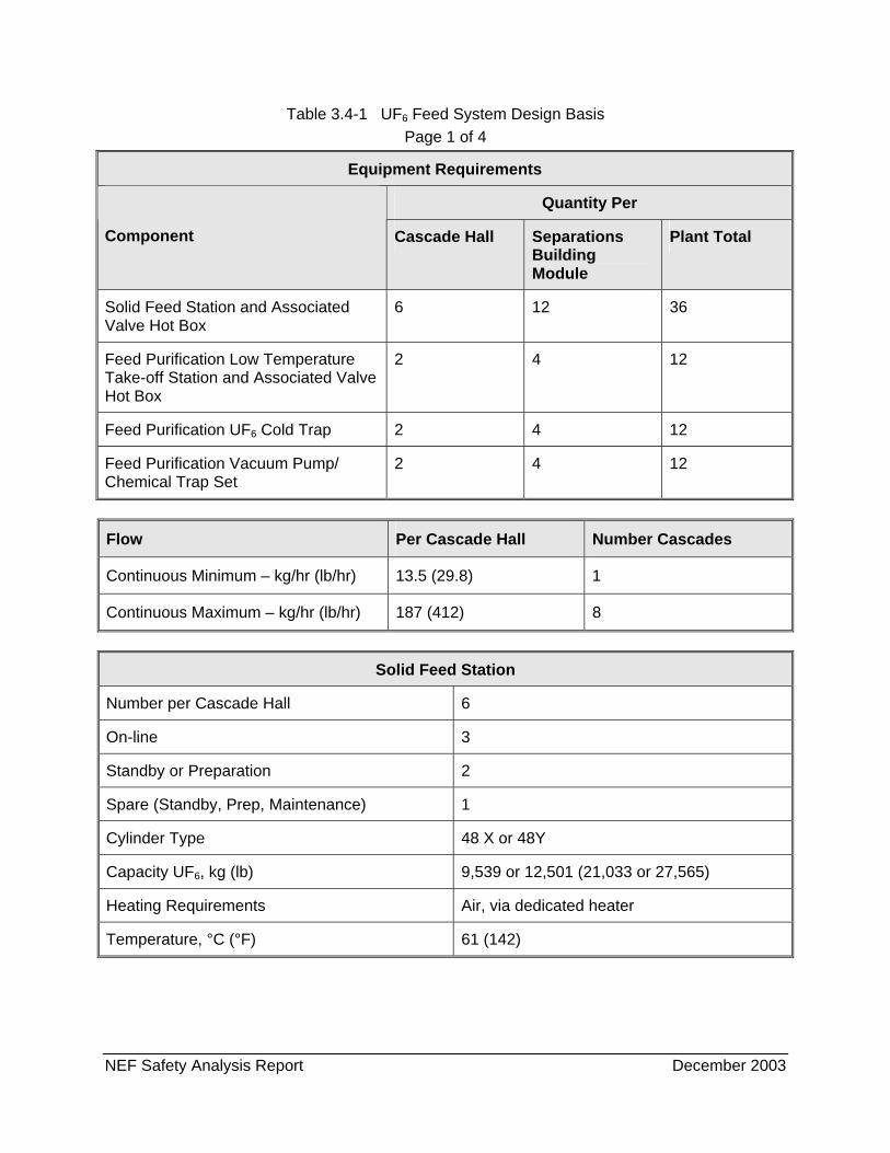
NEF Safety Analysis Report December 2003
Table 3.4-1 UF6 Feed System Design Basis Page 1 of 4
Equipment Requirements
Quantity Per
Component Cascade Hall Separations Building Module
Plant Total
Solid Feed Station and Associated Valve Hot Box
6 12 36
Feed Purification Low Temperature Take-off Station and Associated Valve Hot Box
2 4 12
Feed Purification UF6 Cold Trap 2 4 12
Feed Purification Vacuum Pump/ Chemical Trap Set
2 4 12
Flow Per Cascade Hall Number Cascades
Continuous Minimum – kg/hr (lb/hr) 13.5 (29.8) 1
Continuous Maximum – kg/hr (lb/hr) 187 (412) 8
Solid Feed Station
Number per Cascade Hall 6
On-line 3
Standby or Preparation 2
Spare (Standby, Prep, Maintenance) 1
Cylinder Type 48 X or 48Y
Capacity UF6, kg (lb) 9,539 or 12,501 (21,033 or 27,565)
Heating Requirements Air, via dedicated heater
Temperature, °C (°F) 61 (142)
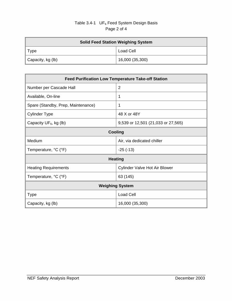
Table 3.4-1 UF6 Feed System Design Basis Page 2 of 4
NEF Safety Analysis Report December 2003
Solid Feed Station Weighing System
Type Load Cell
Capacity, kg (lb) 16,000 (35,300)
Feed Purification Low Temperature Take-off Station
Number per Cascade Hall 2
Available, On-line 1
Spare (Standby, Prep, Maintenance) 1
Cylinder Type 48 X or 48Y
Capacity UF6, kg (lb) 9,539 or 12,501 (21,033 or 27,565)
Cooling
Medium Air, via dedicated chiller
Temperature, °C (°F) -25 (-13)
Heating
Heating Requirements Cylinder Valve Hot Air Blower
Temperature, °C (°F) 63 (145)
Weighing System
Type Load Cell
Capacity, kg (lb) 16,000 (35,300)
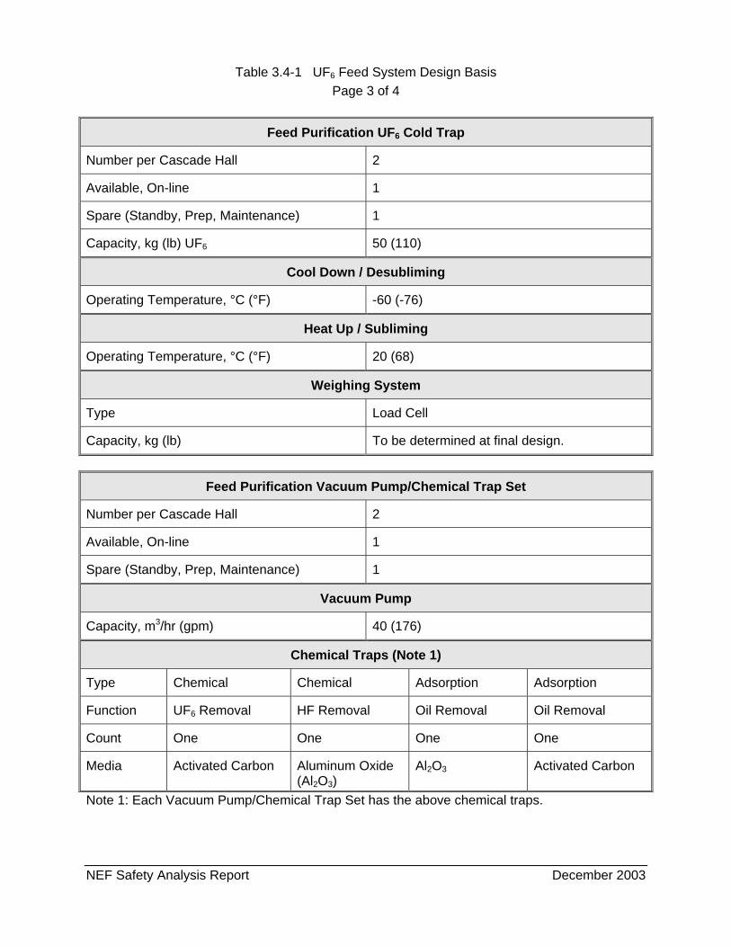
Table 3.4-1 UF6 Feed System Design Basis Page 3 of 4
NEF Safety Analysis Report December 2003
Feed Purification UF6 Cold Trap
Number per Cascade Hall 2
Available, On-line 1
Spare (Standby, Prep, Maintenance) 1
Capacity, kg (lb) UF6 50 (110)
Cool Down / Desubliming
Operating Temperature, °C (°F) -60 (-76)
Heat Up / Subliming
Operating Temperature, °C (°F) 20 (68)
Weighing System
Type Load Cell
Capacity, kg (lb) To be determined at final design.
Feed Purification Vacuum Pump/Chemical Trap Set
Number per Cascade Hall 2
Available, On-line 1
Spare (Standby, Prep, Maintenance) 1
Vacuum Pump
Capacity, m3/hr (gpm) 40 (176)
Chemical Traps (Note 1)
Type Chemical Chemical Adsorption Adsorption
Function UF6 Removal HF Removal Oil Removal Oil Removal
Count One One One One
Media Activated Carbon Aluminum Oxide (Al2O3)
Al2O3 Activated Carbon
Note 1: Each Vacuum Pump/Chemical Trap Set has the above chemical traps.
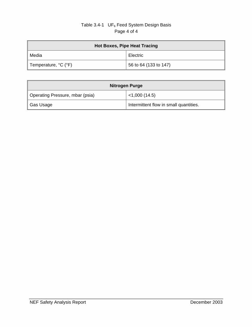
Table 3.4-1 UF6 Feed System Design Basis Page 4 of 4
NEF Safety Analysis Report December 2003
Hot Boxes, Pipe Heat Tracing
Media Electric
Temperature, °C (°F) 56 to 64 (133 to 147)
Nitrogen Purge
Operating Pressure, mbar (psia) <1,000 (14.5)
Gas Usage Intermittent flow in small quantities.
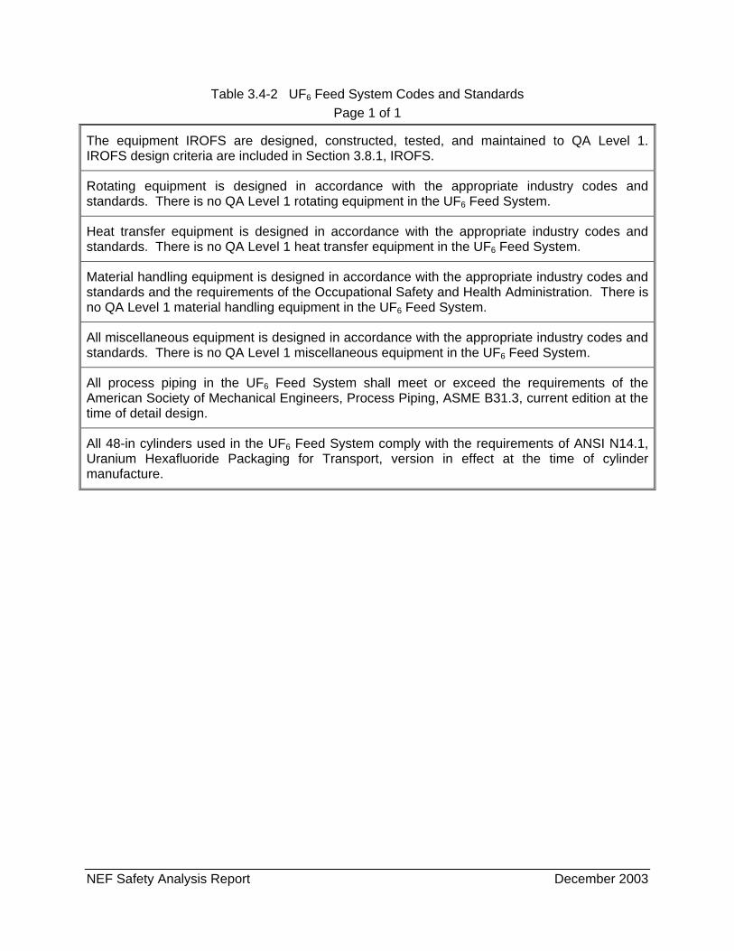
NEF Safety Analysis Report December 2003
Table 3.4-2 UF6 Feed System Codes and Standards Page 1 of 1
The equipment IROFS are designed, constructed, tested, and maintained to QA Level 1. IROFS design criteria are included in Section 3.8.1, IROFS.
Rotating equipment is designed in accordance with the appropriate industry codes and standards. There is no QA Level 1 rotating equipment in the UF6 Feed System.
Heat transfer equipment is designed in accordance with the appropriate industry codes and standards. There is no QA Level 1 heat transfer equipment in the UF6 Feed System.
Material handling equipment is designed in accordance with the appropriate industry codes and standards and the requirements of the Occupational Safety and Health Administration. There is no QA Level 1 material handling equipment in the UF6 Feed System.
All miscellaneous equipment is designed in accordance with the appropriate industry codes and standards. There is no QA Level 1 miscellaneous equipment in the UF6 Feed System.
All process piping in the UF6 Feed System shall meet or exceed the requirements of the American Society of Mechanical Engineers, Process Piping, ASME B31.3, current edition at the time of detail design.
All 48-in cylinders used in the UF6 Feed System comply with the requirements of ANSI N14.1, Uranium Hexafluoride Packaging for Transport, version in effect at the time of cylinder manufacture.
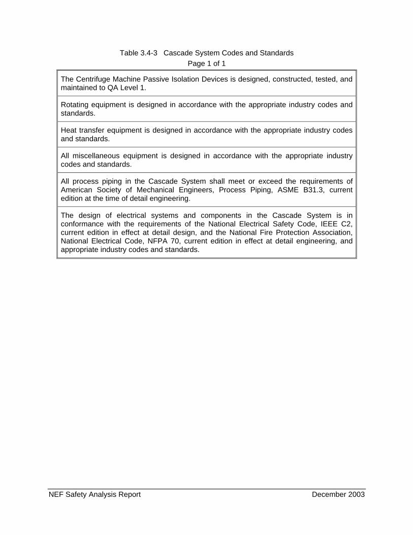
NEF Safety Analysis Report December 2003
Table 3.4-3 Cascade System Codes and Standards Page 1 of 1
The Centrifuge Machine Passive Isolation Devices is designed, constructed, tested, and maintained to QA Level 1.
Rotating equipment is designed in accordance with the appropriate industry codes and standards.
Heat transfer equipment is designed in accordance with the appropriate industry codes and standards.
All miscellaneous equipment is designed in accordance with the appropriate industry codes and standards.
All process piping in the Cascade System shall meet or exceed the requirements of American Society of Mechanical Engineers, Process Piping, ASME B31.3, current edition at the time of detail engineering.
The design of electrical systems and components in the Cascade System is in conformance with the requirements of the National Electrical Safety Code, IEEE C2, current edition in effect at detail design, and the National Fire Protection Association, National Electrical Code, NFPA 70, current edition in effect at detail engineering, and appropriate industry codes and standards.
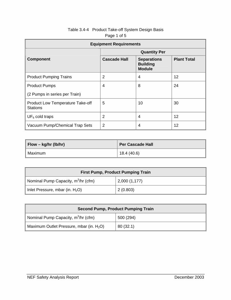
NEF Safety Analysis Report December 2003
Table 3.4-4 Product Take-off System Design Basis Page 1 of 5
Equipment Requirements
Quantity Per Component Cascade Hall Separations
Building Module
Plant Total
Product Pumping Trains 2 4 12
Product Pumps
(2 Pumps in series per Train)
4 8 24
Product Low Temperature Take-off Stations
5 10 30
UF6 cold traps 2 4 12
Vacuum Pump/Chemical Trap Sets 2 4 12
Flow – kg/hr (lb/hr) Per Cascade Hall
Maximum 18.4 (40.6)
First Pump, Product Pumping Train
Nominal Pump Capacity, m3/hr (cfm) 2,000 (1,177)
Inlet Pressure, mbar (in. H2O) 2 (0.803)
Second Pump, Product Pumping Train
Nominal Pump Capacity, m3/hr (cfm) 500 (294)
Maximum Outlet Pressure, mbar (in. H2O) 80 (32.1)
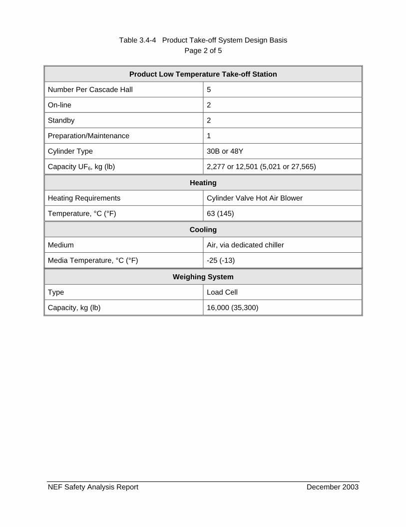
Table 3.4-4 Product Take-off System Design Basis Page 2 of 5
NEF Safety Analysis Report December 2003
Weighing System
Type Load Cell
Capacity, kg (lb) 16,000 (35,300)
Product Low Temperature Take-off Station
Number Per Cascade Hall 5
On-line 2
Standby 2
Preparation/Maintenance 1
Cylinder Type 30B or 48Y
Capacity UF6, kg (lb) 2,277 or 12,501 (5,021 or 27,565)
Heating
Heating Requirements Cylinder Valve Hot Air Blower
Temperature, °C (°F) 63 (145)
Cooling
Medium Air, via dedicated chiller
Media Temperature, °C (°F) -25 (-13)
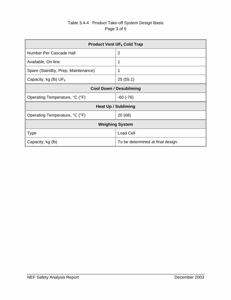
Table 3.4-4 Product Take-off System Design Basis Page 3 of 5
NEF Safety Analysis Report December 2003
Product Vent UF6 Cold Trap
Number Per Cascade Hall 2
Available, On-line 1
Spare (Standby, Prep, Maintenance) 1
Capacity, kg (lb) UF6 25 (55.1)
Cool Down / Desubliming
Operating Temperature, °C (°F) -60 (-76)
Heat Up / Subliming
Operating Temperature, °C (°F) 20 (68)
Weighing System
Type Load Cell
Capacity, kg (lb) To be determined at final design.
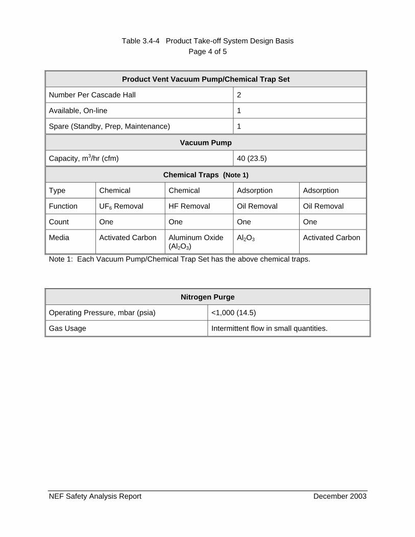
Table 3.4-4 Product Take-off System Design Basis Page 4 of 5
NEF Safety Analysis Report December 2003
Product Vent Vacuum Pump/Chemical Trap Set
Number Per Cascade Hall 2
Available, On-line 1
Spare (Standby, Prep, Maintenance) 1
Vacuum Pump
Capacity, m3/hr (cfm) 40 (23.5)
Chemical Traps (Note 1)
Type Chemical Chemical Adsorption Adsorption
Function UF6 Removal HF Removal Oil Removal Oil Removal
Count One One One One
Media Activated Carbon Aluminum Oxide (Al2O3)
Al2O3 Activated Carbon
Note 1: Each Vacuum Pump/Chemical Trap Set has the above chemical traps.
Nitrogen Purge
Operating Pressure, mbar (psia) <1,000 (14.5)
Gas Usage Intermittent flow in small quantities.
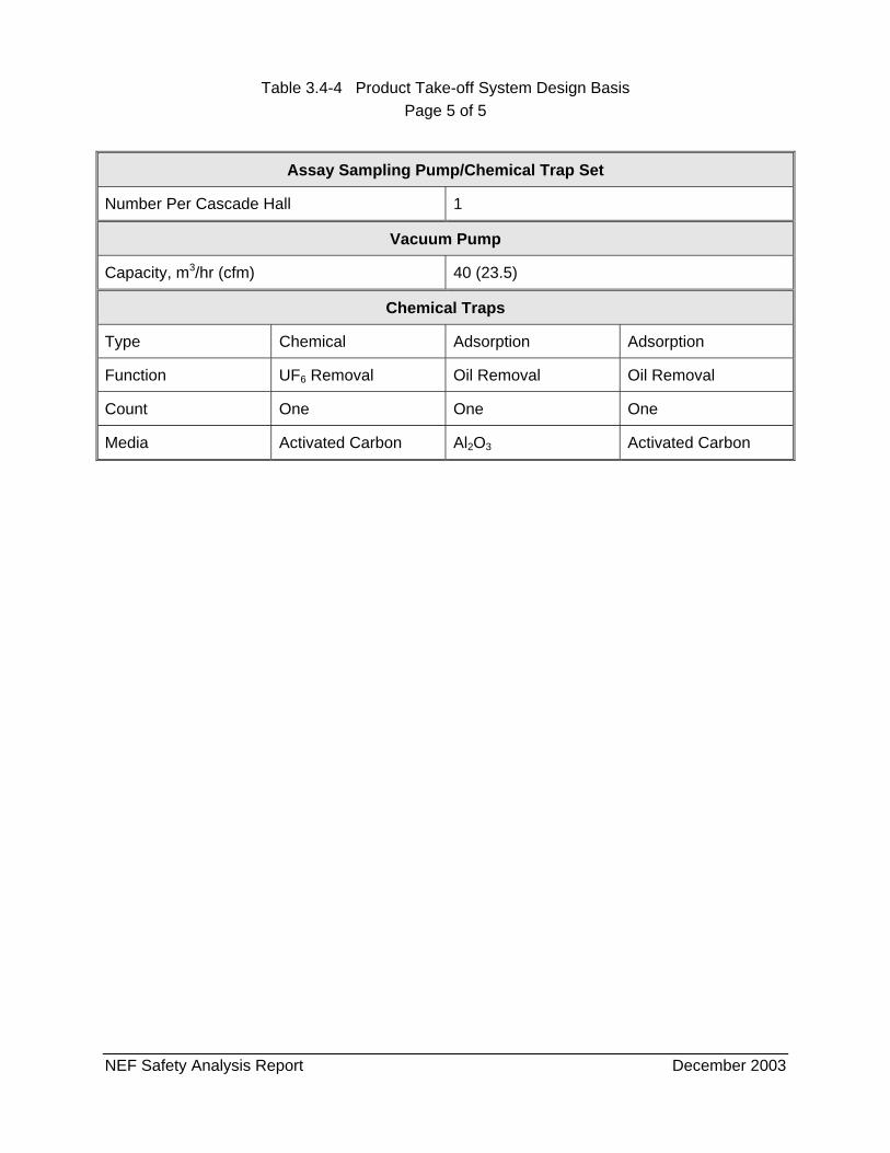
Table 3.4-4 Product Take-off System Design Basis Page 5 of 5
NEF Safety Analysis Report December 2003
Assay Sampling Pump/Chemical Trap Set
Number Per Cascade Hall 1
Vacuum Pump
Capacity, m3/hr (cfm) 40 (23.5)
Chemical Traps
Type Chemical Adsorption Adsorption
Function UF6 Removal Oil Removal Oil Removal
Count One One One
Media Activated Carbon Al2O3 Activated Carbon
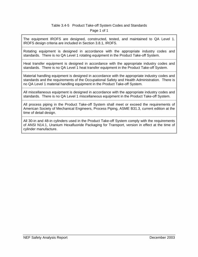
NEF Safety Analysis Report December 2003
Table 3.4-5 Product Take-off System Codes and Standards Page 1 of 1
The equipment IROFS are designed, constructed, tested, and maintained to QA Level 1. IROFS design criteria are included in Section 3.8.1, IROFS.
Rotating equipment is designed in accordance with the appropriate industry codes and standards. There is no QA Level 1 rotating equipment in the Product Take-off System.
Heat transfer equipment is designed in accordance with the appropriate industry codes and standards. There is no QA Level 1 heat transfer equipment in the Product Take-off System.
Material handling equipment is designed in accordance with the appropriate industry codes and standards and the requirements of the Occupational Safety and Health Administration. There is no QA Level 1 material handling equipment in the Product Take-off System.
All miscellaneous equipment is designed in accordance with the appropriate industry codes and standards. There is no QA Level 1 miscellaneous equipment in the Product Take-off System.
All process piping in the Product Take-off System shall meet or exceed the requirements of American Society of Mechanical Engineers, Process Piping, ASME B31.3, current edition at the time of detail design.
All 30-in and 48-in cylinders used in the Product Take-off System comply with the requirements of ANSI N14.1, Uranium Hexafluoride Packaging for Transport, version in effect at the time of cylinder manufacture.
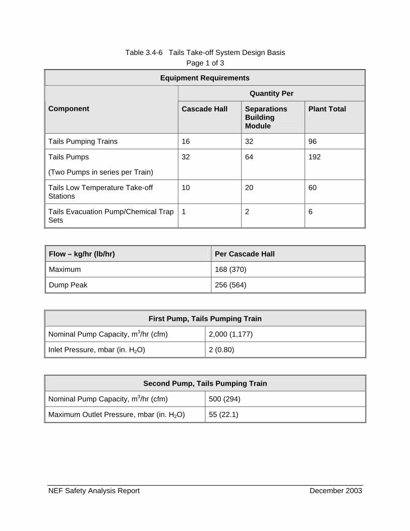
NEF Safety Analysis Report December 2003
Table 3.4-6 Tails Take-off System Design Basis Page 1 of 3
Equipment Requirements
Quantity Per
Component Cascade Hall Separations Building Module
Plant Total
Tails Pumping Trains 16 32 96
Tails Pumps
(Two Pumps in series per Train)
32 64 192
Tails Low Temperature Take-off Stations
10 20 60
Tails Evacuation Pump/Chemical Trap Sets
1 2 6
Flow – kg/hr (lb/hr) Per Cascade Hall
Maximum 168 (370)
Dump Peak 256 (564)
First Pump, Tails Pumping Train
Nominal Pump Capacity, m3/hr (cfm) 2,000 (1,177)
Inlet Pressure, mbar (in. H2O) 2 (0.80)
Second Pump, Tails Pumping Train
Nominal Pump Capacity, m3/hr (cfm) 500 (294)
Maximum Outlet Pressure, mbar (in. H2O) 55 (22.1)
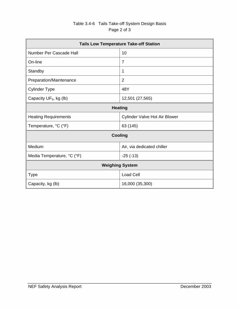
Table 3.4-6 Tails Take-off System Design Basis Page 2 of 3
NEF Safety Analysis Report December 2003
Type Load Cell
Capacity, kg (lb) 16,000 (35,300)
Tails Low Temperature Take-off Station
Number Per Cascade Hall 10
On-line 7
Standby 1
Preparation/Maintenance 2
Cylinder Type 48Y
Capacity UF6, kg (lb) 12,501 (27,565)
Heating
Heating Requirements Cylinder Valve Hot Air Blower
Temperature, °C (°F) 63 (145)
Cooling
Medium Air, via dedicated chiller
Media Temperature, °C (°F) -25 (-13)
Weighing System
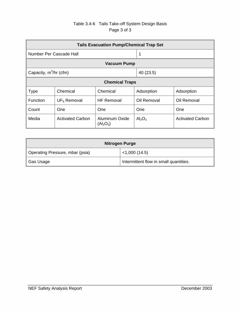
Table 3.4-6 Tails Take-off System Design Basis Page 3 of 3
NEF Safety Analysis Report December 2003
Tails Evacuation Pump/Chemical Trap Set
Number Per Cascade Hall 1
Vacuum Pump
Capacity, m3/hr (cfm) 40 (23.5)
Chemical Traps
Type Chemical Chemical Adsorption Adsorption
Function UF6 Removal HF Removal Oil Removal Oil Removal
Count One One One One
Media Activated Carbon Aluminum Oxide (Al2O3)
Al2O3 Activated Carbon
Nitrogen Purge
Operating Pressure, mbar (psia) <1,000 (14.5)
Gas Usage Intermittent flow in small quantities.

NEF Safety Analysis Report December 2003
Table 3.4-7 Tails Take-off System Codes and Standards Page 1 of 1
The equipment IROFS are designed, constructed, tested, and maintained to QA Level 1. IROFS design criteria are included in Section 3.8.1, IROFS.
Rotating equipment is designed in accordance with the appropriate industry codes and standards. There is no QA Level 1 rotating equipment in the Tails Take-off System.
Heat transfer equipment is designed in accordance with the appropriate industry codes and standards. There is no QA Level 1 heat transfer equipment in the Tails Take-off System.
Material handling equipment is designed in accordance with the appropriate industry codes and standards and the requirements of the Occupational Safety and Health Administration. There is no QA Level 1 material handling equipment in the Tails Take-off System.
All miscellaneous equipment is designed in accordance with the appropriate industry codes and standards. There is no QA Level 1 miscellaneous equipment in the Tails Take-off System.
All process piping in the Tails Take-off System shall meet or exceed the requirements of American Society of Mechanical Engineers, Process Piping, ASME B31.3, current edition at the time of detail design.
All 48-in cylinders used in the Tails Take-off System comply with the requirements of ANSI N14.1, Uranium Hexafluoride Packaging for Transport, version in effect at the time of cylinder manufacture.
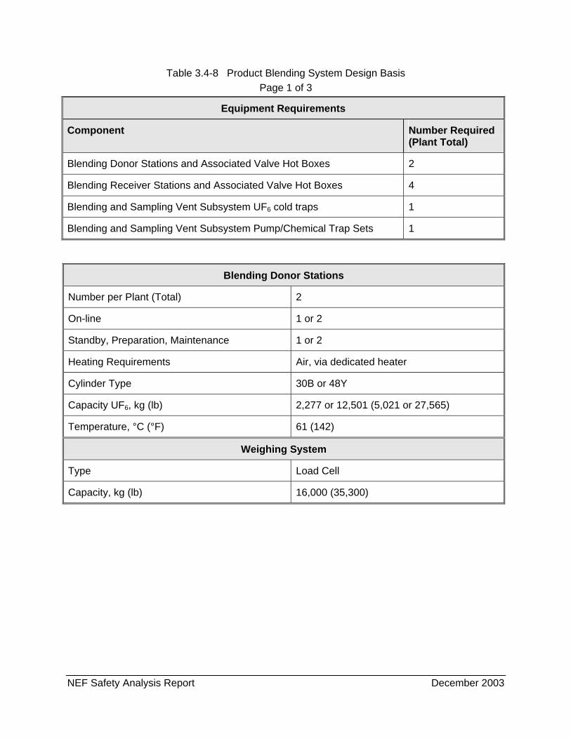
NEF Safety Analysis Report December 2003
Table 3.4-8 Product Blending System Design Basis Page 1 of 3
Equipment Requirements
Component Number Required (Plant Total)
Blending Donor Stations and Associated Valve Hot Boxes 2
Blending Receiver Stations and Associated Valve Hot Boxes 4
Blending and Sampling Vent Subsystem UF6 cold traps 1
Blending and Sampling Vent Subsystem Pump/Chemical Trap Sets 1
Blending Donor Stations
Number per Plant (Total) 2
On-line 1 or 2
Standby, Preparation, Maintenance 1 or 2
Heating Requirements Air, via dedicated heater
Cylinder Type 30B or 48Y
Capacity UF6, kg (lb) 2,277 or 12,501 (5,021 or 27,565)
Temperature, °C (°F) 61 (142)
Weighing System
Type Load Cell
Capacity, kg (lb) 16,000 (35,300)
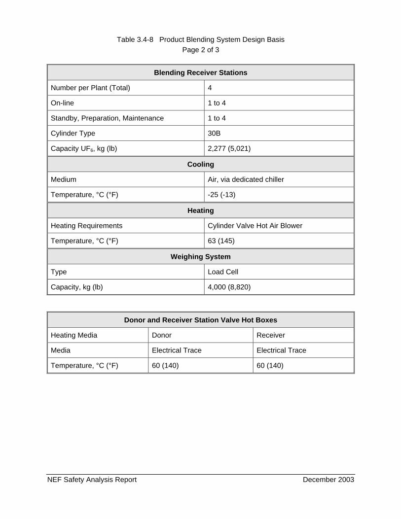
Table 3.4-8 Product Blending System Design Basis Page 2 of 3
NEF Safety Analysis Report December 2003
Blending Receiver Stations
Number per Plant (Total) 4
On-line 1 to 4
Standby, Preparation, Maintenance 1 to 4
Cylinder Type 30B
Capacity UF6, kg (lb) 2,277 (5,021)
Cooling
Medium Air, via dedicated chiller
Temperature, °C (°F) -25 (-13)
Heating
Heating Requirements Cylinder Valve Hot Air Blower
Temperature, °C (°F) 63 (145)
Weighing System
Type Load Cell
Capacity, kg (lb) 4,000 (8,820)
Donor and Receiver Station Valve Hot Boxes
Heating Media Donor Receiver
Media Electrical Trace Electrical Trace
Temperature, °C (°F) 60 (140) 60 (140)
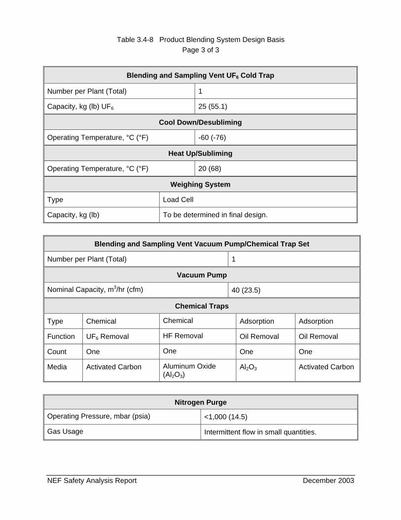
Table 3.4-8 Product Blending System Design Basis Page 3 of 3
NEF Safety Analysis Report December 2003
Blending and Sampling Vent UF6 Cold Trap
Number per Plant (Total) 1
Capacity, kg (lb) UF6 25 (55.1)
Cool Down/Desubliming
Operating Temperature, °C (°F) -60 (-76)
Heat Up/Subliming
Operating Temperature, °C (°F) 20 (68)
Weighing System
Type Load Cell
Capacity, kg (lb) To be determined in final design.
Blending and Sampling Vent Vacuum Pump/Chemical Trap Set
Number per Plant (Total) 1
Vacuum Pump
Nominal Capacity, m3/hr (cfm) 40 (23.5)
Chemical Traps
Type Chemical Chemical Adsorption Adsorption
Function UF6 Removal HF Removal Oil Removal Oil Removal
Count One One One One
Media Activated Carbon Aluminum Oxide (Al2O3)
Al2O3 Activated Carbon
Nitrogen Purge
Operating Pressure, mbar (psia) <1,000 (14.5)
Gas Usage Intermittent flow in small quantities.
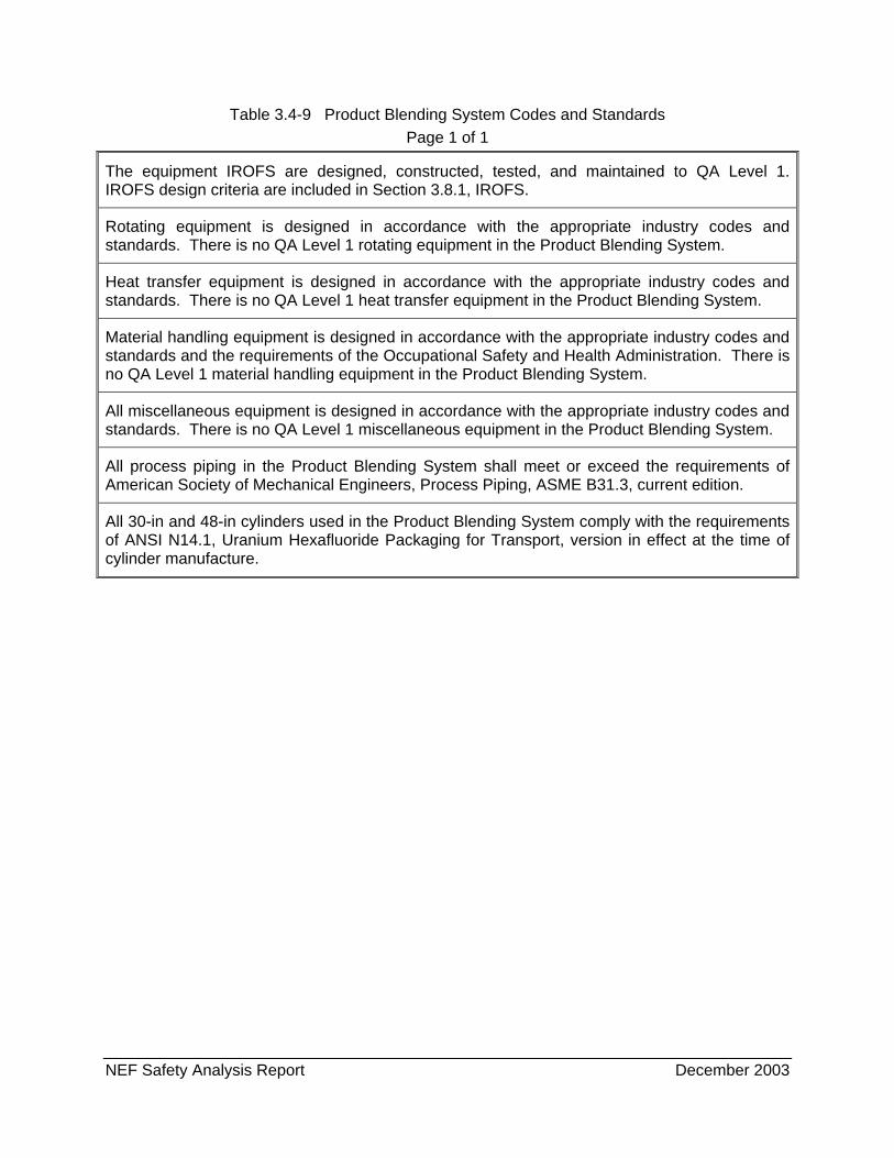
NEF Safety Analysis Report December 2003
Table 3.4-9 Product Blending System Codes and Standards Page 1 of 1
The equipment IROFS are designed, constructed, tested, and maintained to QA Level 1. IROFS design criteria are included in Section 3.8.1, IROFS.
Rotating equipment is designed in accordance with the appropriate industry codes and standards. There is no QA Level 1 rotating equipment in the Product Blending System.
Heat transfer equipment is designed in accordance with the appropriate industry codes and standards. There is no QA Level 1 heat transfer equipment in the Product Blending System.
Material handling equipment is designed in accordance with the appropriate industry codes and standards and the requirements of the Occupational Safety and Health Administration. There is no QA Level 1 material handling equipment in the Product Blending System.
All miscellaneous equipment is designed in accordance with the appropriate industry codes and standards. There is no QA Level 1 miscellaneous equipment in the Product Blending System.
All process piping in the Product Blending System shall meet or exceed the requirements of American Society of Mechanical Engineers, Process Piping, ASME B31.3, current edition.
All 30-in and 48-in cylinders used in the Product Blending System comply with the requirements of ANSI N14.1, Uranium Hexafluoride Packaging for Transport, version in effect at the time of cylinder manufacture.
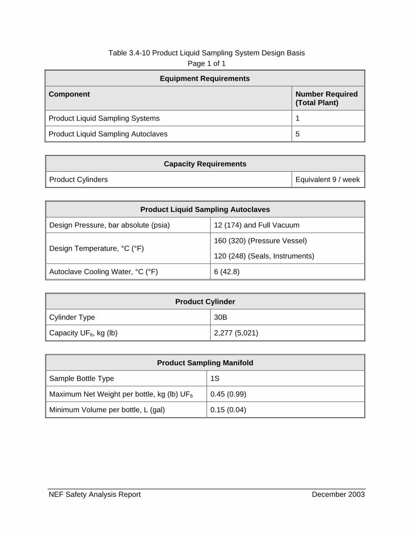
NEF Safety Analysis Report December 2003
Table 3.4-10 Product Liquid Sampling System Design Basis Page 1 of 1
Equipment Requirements
Component Number Required (Total Plant)
Product Liquid Sampling Systems 1
Product Liquid Sampling Autoclaves 5
Capacity Requirements
Product Cylinders Equivalent 9 / week
Product Liquid Sampling Autoclaves
Design Pressure, bar absolute (psia) 12 (174) and Full Vacuum
Design Temperature, °C (°F) 160 (320) (Pressure Vessel)
120 (248) (Seals, Instruments)
Autoclave Cooling Water, °C (°F) 6 (42.8)
Product Cylinder
Cylinder Type 30B
Capacity UF6, kg (lb) 2,277 (5,021)
Product Sampling Manifold
Sample Bottle Type 1S
Maximum Net Weight per bottle, kg (lb) UF6 0.45 (0.99)
Minimum Volume per bottle, L (gal) 0.15 (0.04)
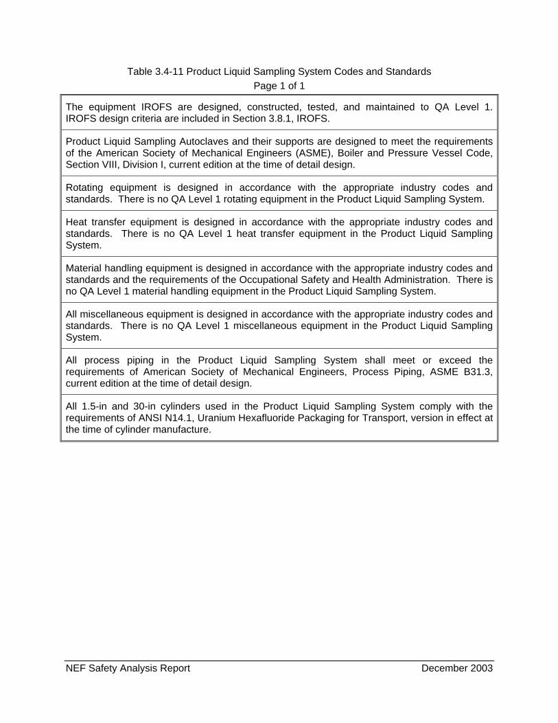
NEF Safety Analysis Report December 2003
Table 3.4-11 Product Liquid Sampling System Codes and Standards Page 1 of 1
The equipment IROFS are designed, constructed, tested, and maintained to QA Level 1. IROFS design criteria are included in Section 3.8.1, IROFS.
Product Liquid Sampling Autoclaves and their supports are designed to meet the requirements of the American Society of Mechanical Engineers (ASME), Boiler and Pressure Vessel Code, Section VIII, Division I, current edition at the time of detail design.
Rotating equipment is designed in accordance with the appropriate industry codes and standards. There is no QA Level 1 rotating equipment in the Product Liquid Sampling System.
Heat transfer equipment is designed in accordance with the appropriate industry codes and standards. There is no QA Level 1 heat transfer equipment in the Product Liquid Sampling System.
Material handling equipment is designed in accordance with the appropriate industry codes and standards and the requirements of the Occupational Safety and Health Administration. There is no QA Level 1 material handling equipment in the Product Liquid Sampling System.
All miscellaneous equipment is designed in accordance with the appropriate industry codes and standards. There is no QA Level 1 miscellaneous equipment in the Product Liquid Sampling System.
All process piping in the Product Liquid Sampling System shall meet or exceed the requirements of American Society of Mechanical Engineers, Process Piping, ASME B31.3, current edition at the time of detail design.
All 1.5-in and 30-in cylinders used in the Product Liquid Sampling System comply with the requirements of ANSI N14.1, Uranium Hexafluoride Packaging for Transport, version in effect at the time of cylinder manufacture.
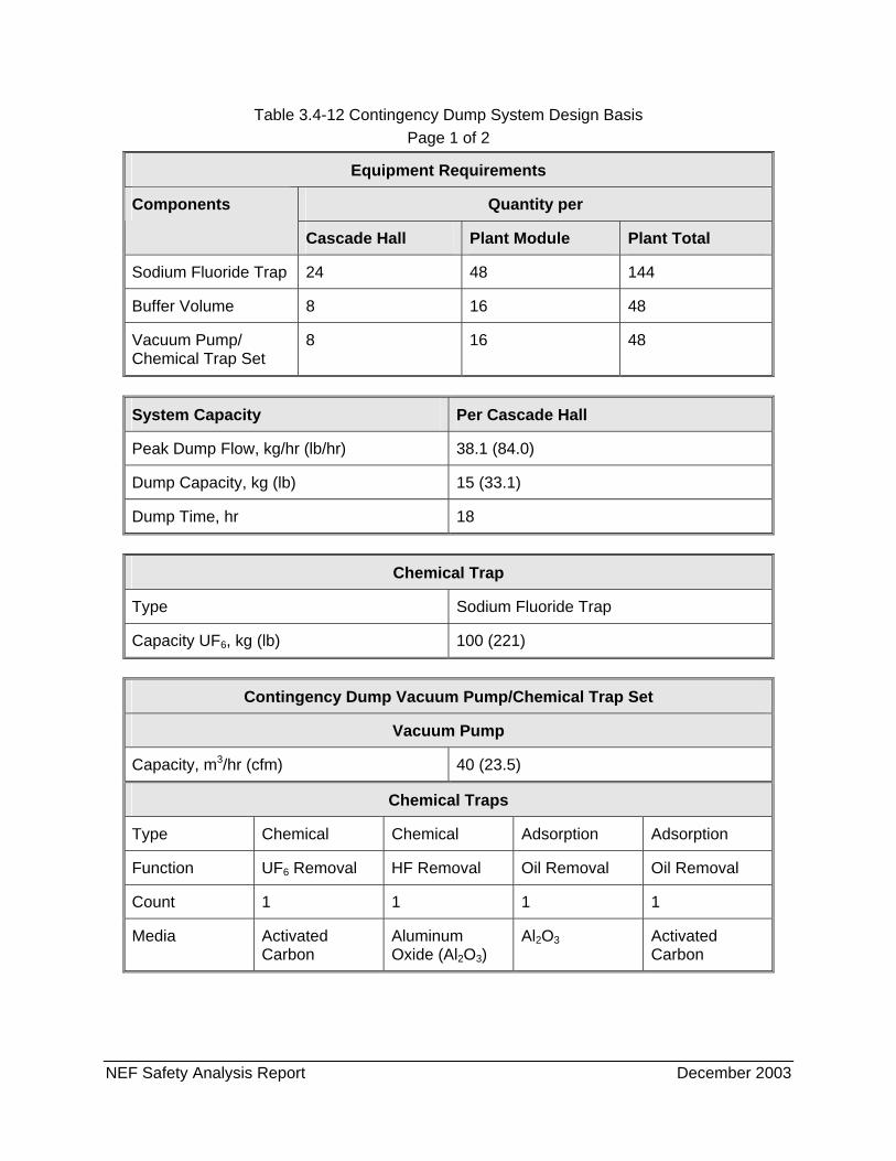
NEF Safety Analysis Report December 2003
Table 3.4-12 Contingency Dump System Design Basis Page 1 of 2
Equipment Requirements
Quantity per Components
Cascade Hall Plant Module Plant Total
Sodium Fluoride Trap 24 48 144
Buffer Volume 8 16 48
Vacuum Pump/ Chemical Trap Set
8 16 48
System Capacity Per Cascade Hall
Peak Dump Flow, kg/hr (lb/hr) 38.1 (84.0)
Dump Capacity, kg (lb) 15 (33.1)
Dump Time, hr 18
Chemical Trap
Type Sodium Fluoride Trap
Capacity UF6, kg (lb) 100 (221)
Contingency Dump Vacuum Pump/Chemical Trap Set
Vacuum Pump
Capacity, m3/hr (cfm) 40 (23.5)
Chemical Traps
Type Chemical Chemical Adsorption Adsorption
Function UF6 Removal HF Removal Oil Removal Oil Removal
Count 1 1 1 1
Media Activated Carbon
Aluminum Oxide (Al2O3)
Al2O3 Activated Carbon
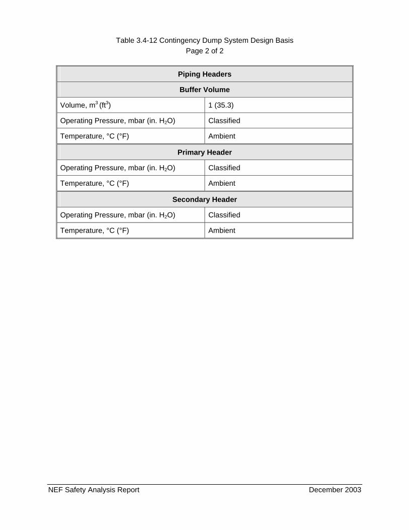
Table 3.4-12 Contingency Dump System Design Basis Page 2 of 2
NEF Safety Analysis Report December 2003
Piping Headers
Buffer Volume
Volume, m3 (ft3) 1 (35.3)
Operating Pressure, mbar (in. H2O) Classified
Temperature, °C (°F) Ambient
Primary Header
Operating Pressure, mbar (in. H2O) Classified
Temperature, °C (°F) Ambient
Secondary Header
Operating Pressure, mbar (in. H2O) Classified
Temperature, °C (°F) Ambient
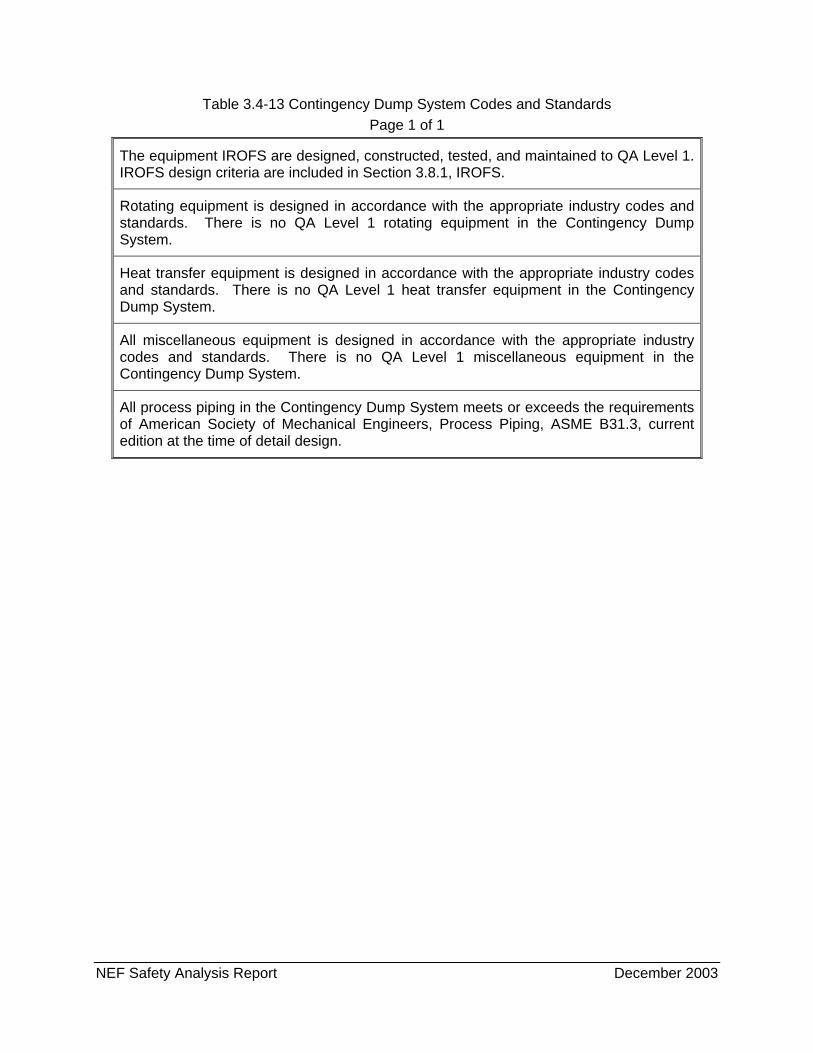
NEF Safety Analysis Report December 2003
Table 3.4-13 Contingency Dump System Codes and Standards Page 1 of 1
The equipment IROFS are designed, constructed, tested, and maintained to QA Level 1. IROFS design criteria are included in Section 3.8.1, IROFS.
Rotating equipment is designed in accordance with the appropriate industry codes and standards. There is no QA Level 1 rotating equipment in the Contingency Dump System.
Heat transfer equipment is designed in accordance with the appropriate industry codes and standards. There is no QA Level 1 heat transfer equipment in the Contingency Dump System.
All miscellaneous equipment is designed in accordance with the appropriate industry codes and standards. There is no QA Level 1 miscellaneous equipment in the Contingency Dump System.
All process piping in the Contingency Dump System meets or exceeds the requirements of American Society of Mechanical Engineers, Process Piping, ASME B31.3, current edition at the time of detail design.
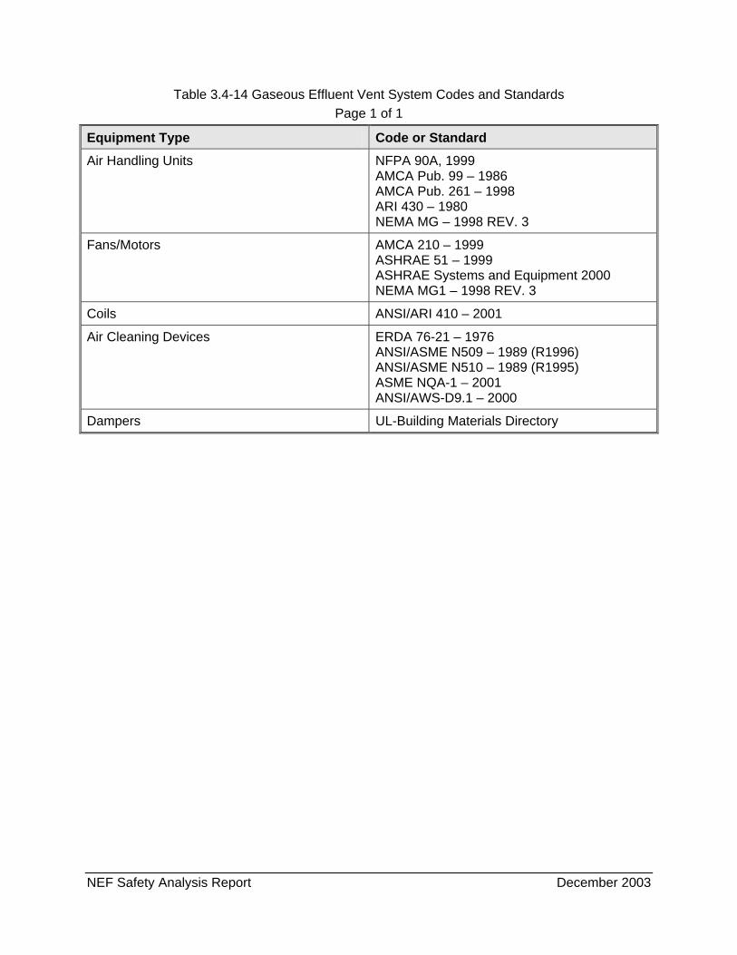
NEF Safety Analysis Report December 2003
Table 3.4-14 Gaseous Effluent Vent System Codes and Standards Page 1 of 1
Equipment Type Code or Standard Air Handling Units NFPA 90A, 1999
AMCA Pub. 99 – 1986 AMCA Pub. 261 – 1998 ARI 430 – 1980 NEMA MG – 1998 REV. 3
Fans/Motors AMCA 210 – 1999 ASHRAE 51 – 1999 ASHRAE Systems and Equipment 2000 NEMA MG1 – 1998 REV. 3
Coils ANSI/ARI 410 – 2001
Air Cleaning Devices ERDA 76-21 – 1976 ANSI/ASME N509 – 1989 (R1996) ANSI/ASME N510 – 1989 (R1995) ASME NQA-1 – 2001 ANSI/AWS-D9.1 – 2000
Dampers UL-Building Materials Directory

NEF Safety Analysis Report December 2003
Table 3.4-15 Gaseous Effluent Vent System Design Bases (Separations Building) Page 1 of 1
Equipment Requirements
Item Quantity
Filter Stations (prefilter, HEPA, activated carbon filter) 1 + 1 spare
Fans 1 + 1 spare
System Design Flow Rate 11,000 m3/hr (6474 scfm)
Filter Specifications
Prefilter (Dust removal) 85%
HEPA Filter (Removal of uranium aerosols, mainly UO2F2 particles)
99.97%
(for ≥ 0.3 µm particle size)
Activated Carbon Filter (HF removal) 99.9%
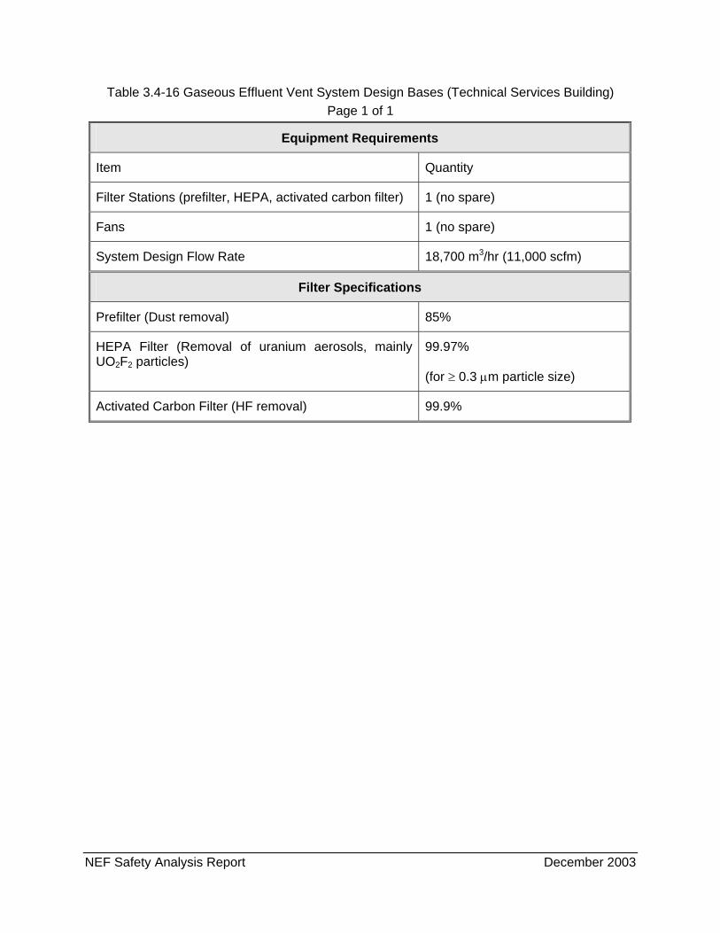
NEF Safety Analysis Report December 2003
Table 3.4-16 Gaseous Effluent Vent System Design Bases (Technical Services Building) Page 1 of 1
Equipment Requirements
Item Quantity
Filter Stations (prefilter, HEPA, activated carbon filter) 1 (no spare)
Fans 1 (no spare)
System Design Flow Rate 18,700 m3/hr (11,000 scfm)
Filter Specifications
Prefilter (Dust removal) 85%
HEPA Filter (Removal of uranium aerosols, mainly UO2F2 particles)
99.97%
(for ≥ 0.3 µm particle size)
Activated Carbon Filter (HF removal) 99.9%
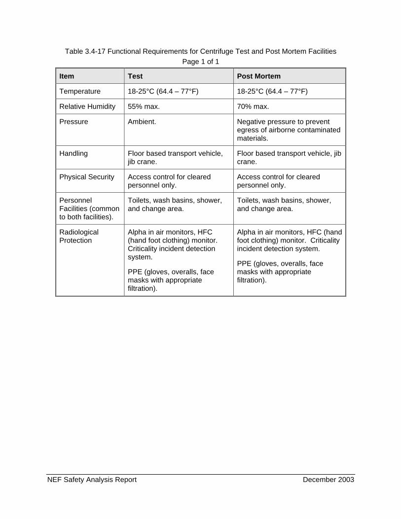
NEF Safety Analysis Report December 2003
Table 3.4-17 Functional Requirements for Centrifuge Test and Post Mortem Facilities Page 1 of 1
Item Test Post Mortem
Temperature 18-25°C (64.4 – 77°F) 18-25°C (64.4 – 77°F)
Relative Humidity 55% max. 70% max.
Pressure Ambient. Negative pressure to prevent egress of airborne contaminated materials.
Handling Floor based transport vehicle, jib crane.
Floor based transport vehicle, jib crane.
Physical Security Access control for cleared personnel only.
Access control for cleared personnel only.
Personnel Facilities (common to both facilities).
Toilets, wash basins, shower, and change area.
Toilets, wash basins, shower, and change area.
Radiological Protection
Alpha in air monitors, HFC (hand foot clothing) monitor. Criticality incident detection system.
PPE (gloves, overalls, face masks with appropriate filtration).
Alpha in air monitors, HFC (hand foot clothing) monitor. Criticality incident detection system.
PPE (gloves, overalls, face masks with appropriate filtration).
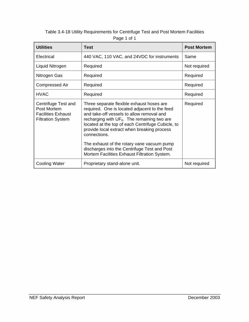
NEF Safety Analysis Report December 2003
Table 3.4-18 Utility Requirements for Centrifuge Test and Post Mortem Facilities Page 1 of 1
Utilities Test Post Mortem
Electrical 440 VAC, 110 VAC, and 24VDC for instruments Same
Liquid Nitrogen Required Not required
Nitrogen Gas Required Required
Compressed Air Required Required
HVAC Required Required
Centrifuge Test and Post Mortem Facilities Exhaust Filtration System
Three separate flexible exhaust hoses are required. One is located adjacent to the feed and take-off vessels to allow removal and recharging with UF6. The remaining two are located at the top of each Centrifuge Cubicle, to provide local extract when breaking process connections.
The exhaust of the rotary vane vacuum pump discharges into the Centrifuge Test and Post Mortem Facilities Exhaust Filtration System.
Required
Cooling Water Proprietary stand-alone unit. Not required
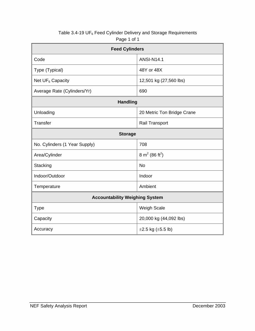
NEF Safety Analysis Report December 2003
Table 3.4-19 UF6 Feed Cylinder Delivery and Storage Requirements Page 1 of 1
Feed Cylinders
Code ANSI-N14.1
Type (Typical) 48Y or 48X
Net UF6 Capacity 12,501 kg (27,560 lbs)
Average Rate (Cylinders/Yr) 690
Handling
Unloading 20 Metric Ton Bridge Crane
Transfer Rail Transport
Storage
No. Cylinders (1 Year Supply) 708
Area/Cylinder 8 m2 (86 ft2)
Stacking No
Indoor/Outdoor Indoor
Temperature Ambient
Accountability Weighing System
Type Weigh Scale
Capacity 20,000 kg (44,092 lbs)
Accuracy ±2.5 kg (±5.5 lb)
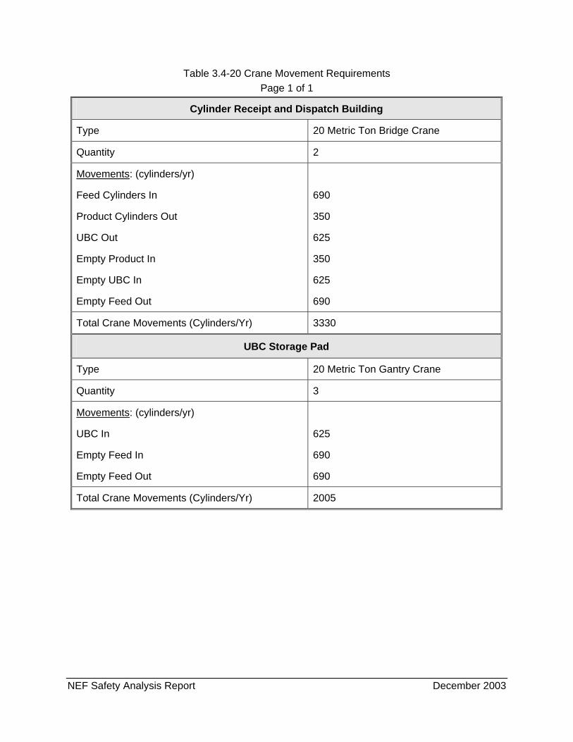
NEF Safety Analysis Report December 2003
Table 3.4-20 Crane Movement Requirements Page 1 of 1
Cylinder Receipt and Dispatch Building
Type 20 Metric Ton Bridge Crane
Quantity 2
Movements: (cylinders/yr)
Feed Cylinders In
Product Cylinders Out
UBC Out
Empty Product In
Empty UBC In
Empty Feed Out
690
350
625
350
625
690
Total Crane Movements (Cylinders/Yr) 3330
UBC Storage Pad
Type 20 Metric Ton Gantry Crane
Quantity 3
Movements: (cylinders/yr)
UBC In
Empty Feed In
Empty Feed Out
625
690
690
Total Crane Movements (Cylinders/Yr) 2005
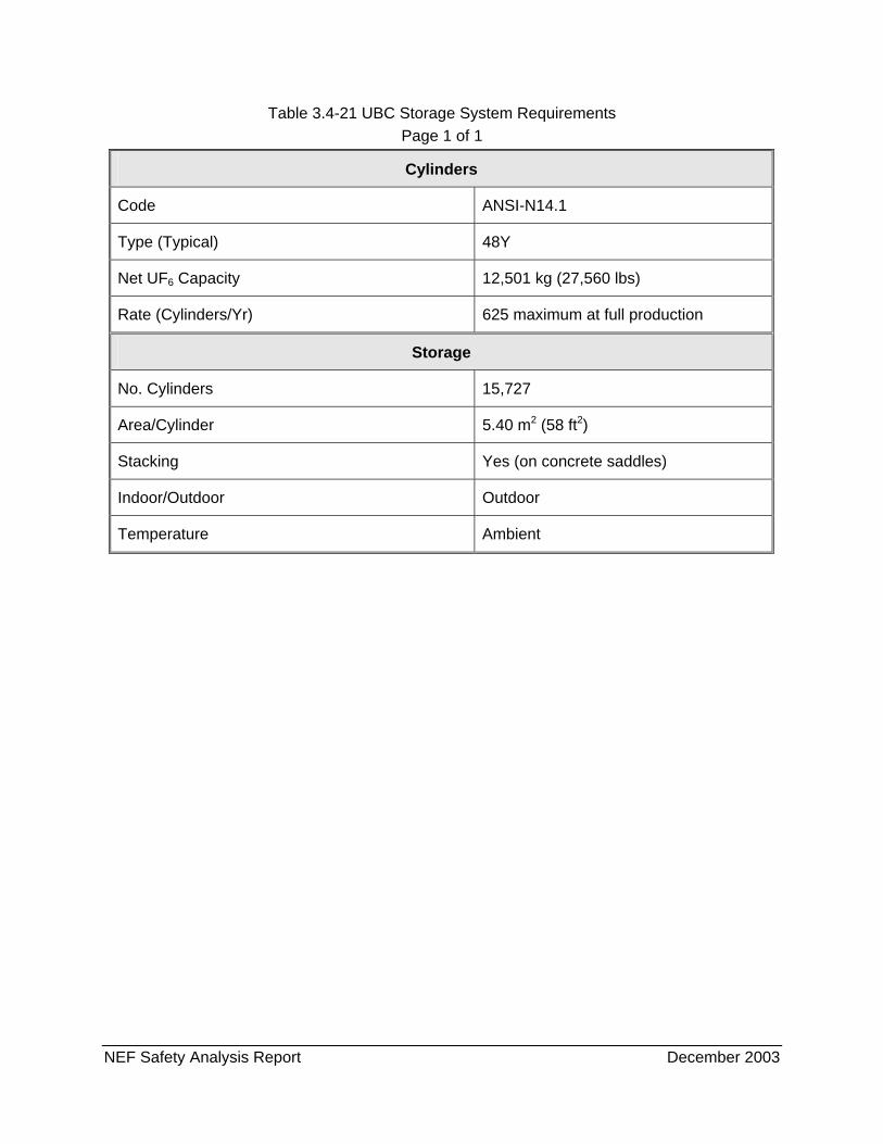
NEF Safety Analysis Report December 2003
Table 3.4-21 UBC Storage System Requirements Page 1 of 1
Cylinders
Code ANSI-N14.1
Type (Typical) 48Y
Net UF6 Capacity 12,501 kg (27,560 lbs)
Rate (Cylinders/Yr) 625 maximum at full production
Storage
No. Cylinders 15,727
Area/Cylinder 5.40 m2 (58 ft2)
Stacking Yes (on concrete saddles)
Indoor/Outdoor Outdoor
Temperature Ambient
NEF Safety Analysis Report December 2003
FIGURES