Embed Size (px)
Citation preview
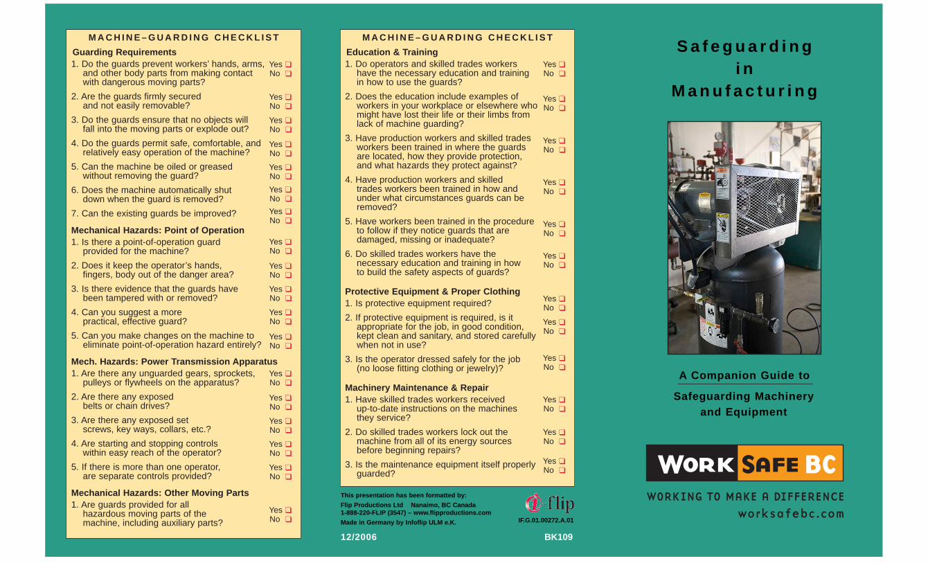
S a f e g u a r d i n gi n
M a n u f a c t u r i n g
M A C H I N E – G U A R D I N G C H E C K L I S T
Guarding Requirements1. Do the guards prevent workers’ hands, arms,
and other body parts from making contactwith dangerous moving parts?
2. Are the guards firmly securedand not easily removable?
3. Do the guards ensure that no objects willfall into the moving parts or explode out?
4. Do the guards permit safe, comfortable, andrelatively easy operation of the machine?
5. Can the machine be oiled or greasedwithout removing the guard?
6. Does the machine automatically shutdown when the guard is removed?
7. Can the existing guards be improved?
Mechanical Hazards: Point of Operation1. Is there a point-of-operation guard
provided for the machine?
2. Does it keep the operator’s hands,fingers, body out of the danger area?
3. Is there evidence that the guards havebeen tampered with or removed?
4. Can you suggest a morepractical, effective guard?
5. Can you make changes on the machine toeliminate point-of-operation hazard entirely?
Mech. Hazards: Power Transmission Apparatus1. Are there any unguarded gears, sprockets,
pulleys or flywheels on the apparatus?
2. Are there any exposedbelts or chain drives?
3. Are there any exposed setscrews, key ways, collars, etc.?
4. Are starting and stopping controlswithin easy reach of the operator?
5. If there is more than one operator,are separate controls provided?
Mechanical Hazards: Other Moving Parts1. Are guards provided for all
hazardous moving parts of themachine, including auxiliary parts?
A Companion Guide to
Safeguarding Machineryand Equipment
Yes ❑No ❑
Yes ❑No ❑
Yes ❑No ❑
Yes ❑No ❑
Yes ❑No ❑
Yes ❑No ❑
Yes ❑No ❑
Yes ❑No ❑
Yes ❑No ❑
Yes ❑No ❑
Yes ❑No ❑
Yes ❑No ❑
Yes ❑No ❑
Yes ❑No ❑
Yes ❑No ❑
Yes ❑No ❑
Yes ❑No ❑
Yes ❑No ❑
M A C H I N E – G U A R D I N G C H E C K L I S T
Education & Training1. Do operators and skilled trades workers
have the necessary education and trainingin how to use the guards?
2. Does the education include examples ofworkers in your workplace or elsewhere whomight have lost their life or their limbs fromlack of machine guarding?
3. Have production workers and skilled tradesworkers been trained in where the guardsare located, how they provide protection,and what hazards they protect against?
4. Have production workers and skilledtrades workers been trained in how andunder what circumstances guards can beremoved?
5. Have workers been trained in the procedureto follow if they notice guards that aredamaged, missing or inadequate?
6. Do skilled trades workers have thenecessary education and training in howto build the safety aspects of guards?
Protective Equipment & Proper Clothing1. Is protective equipment required?
2. If protective equipment is required, is itappropriate for the job, in good condition,kept clean and sanitary, and stored carefullywhen not in use?
3. Is the operator dressed safely for the job(no loose fitting clothing or jewelry)?
Machinery Maintenance & Repair1. Have skilled trades workers received
up-to-date instructions on the machinesthey service?
2. Do skilled trades workers lock out themachine from all of its energy sourcesbefore beginning repairs?
3. Is the maintenance equipment itself properlyguarded?
Yes ❑No ❑
Yes ❑No ❑
Yes ❑No ❑
Yes ❑No ❑
Yes ❑No ❑
Yes ❑No ❑
Yes ❑No ❑
Yes ❑No ❑
Yes ❑No ❑
Yes ❑No ❑
Yes ❑No ❑
Yes ❑No ❑
This presentation has been formatted by:
Flip Productions Ltd Nanaimo, BC Canada1-888-220-FLIP (3547) – www.flipproductions.com
Made in Germany by Infoflip ULM e.K. IF.G.01.00272.A.01
BK10912/2006

WorksafeBC makes no representations, warranties, orcondition, expressed or implied, that this document is andwill remain accurate at all times. WorkSafeBC is notresponsible for direct, indirect, special, or consequentialdamages, however caused, arising from the use of thisdocument and its information. Employers and workersshould always refer to the Act/Regulation and applicableguidelines for specific requirements that apply to their workoperations and activities.
For more information, please refer to the full manual:Safeguarding Machinery and Equipment
General Requirements(WorksafeBC #BK101)
Safeguarding Controls
❑ Eliminate human interaction in the process❑ Eliminate pinch points❑ Automate material handling
❑ Mechanical hard stops ❑ Interlocked guards❑ Barrier guards ❑ 2-handed controls❑ Presence-sensing devices
❑ Computer warnings ❑ Lights, beacons, ❑ Warning signs/labels ❑ Strobes, beepers❑ “Restricted Space” ❑ Horns and sirens
painted on floor
❑ Safe work procedures ❑ Training❑ Safety Equipment Inspections ❑ Lockout
❑ Safety eyewear ❑ Gloves❑ Hearing protection ❑ Respirator❑ Face shield ❑ Hardhat❑ Steel toe safety boots
MOSTEffective
LEASTEffective
1. Elimination/Substitution
2. EngineeringControls
3. Awareness
4. Training &Procedures
5. PPE
This Infoflip is a companion guide and is merelyintended to draw attention to some hazards andpreventative safeguarding measures: the user isrequired to do a complete hazard analysis
Hierarchy of Safeguarding Controls

This infoflip was produced to help:
✎ Employers to comply with the OccupationalHealth and Safety Regulation (OHSR) and Part3 of the Workers Compensation Act, and toexercise due diligence in providing a safe workenvironment
✎ Supervisors to assess risks to their workersfrom harmful contact with machinery andequipment, and to evaluate safeguardingsolutions that satisfy the competing needs ofsafety, production, and quality assurance
✎ Workers to gain greater awareness of thehazards associated with equipment operationand maintenance, and of the safeguardingprotection they have a right to expect
✎ Suppliers to understand the requirements formachinery and equipment to conform to theWorkers Compensation Act and the OHSR
✎ Individuals involved in risk assessment,maintenance, operations management, andhealth and safety committees.
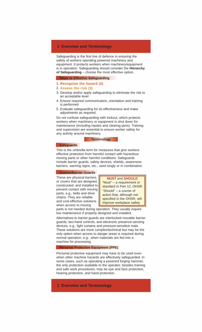
Safeguarding is the first line of defence in ensuring thesafety of workers operating powered machinery andequipment. It protects workers when machinery/equipmentis in operation. Safeguarding should consider the Hierarchyof Safeguarding – choose the most effective option.
Steps to Effective Safeguarding
1. Recognize the hazard (2)Recognize the hazard (2)2. Assess the risk (3)Assess the risk (3)3. Develop and/or apply safeguarding to eliminate the risk to
an acceptable level4. Ensure required communication, orientation and training
is performed5. Evaluate safeguarding for its effectiveness and make
adjustments as required.
Do not confuse safeguarding with lockout, which protectsworkers when machinery or equipment is shut down formaintenance (including repairs and clearing jams). Trainingand supervision are essential to ensure worker safety forany activity around machinery.
Terminology
SafeguardsThis is the umbrella term for measures that give workerseffective protection from harmful contact with hazardousmoving parts or other harmful conditions. Safeguardsinclude barrier guards, safety devices, shields, awarenessbarriers, warning signs, etc., used singly or in combination.
Guards/Barrier GuardsThese are physical barriersor covers that are designed,constructed, and installed toprevent contact with movingparts, e.g., belts and drivechains. They are reliableand cost-effective solutionswhen access to movingparts is not needed during operation. They usually requirelow maintenance if properly designed and installed.
Alternatives to barrier guards are interlocked movable barrierguards, two-hand controls, and electronic presence-sensingdevices, e.g., light curtains and pressure-sensitive mats.These solutions are more complex/technical but may be theonly option when access to danger areas is required duringnormal operation, e.g., when materials are fed into amachine for processing.
Personal Protective Equipment (PPE)
Personal protective equipment may have to be used evenwhen other machine hazards are effectively safeguarded. Insome cases, such as operating a powered forging hammer,the only protection available to the operator, besides trainingand safe work procedures, may be eye and face protection,hearing protection, and hand protection.
1 Overview and Terminology
1 Overview and Terminology
MUST and SHOULD“Must” – a requirement orstandard in Part 12, OHSR “Should” – a course ofaction that, although notspecified in the OHSR, willimprove workplace safety
2 Hazard Recognition
2 Hazard Recognition
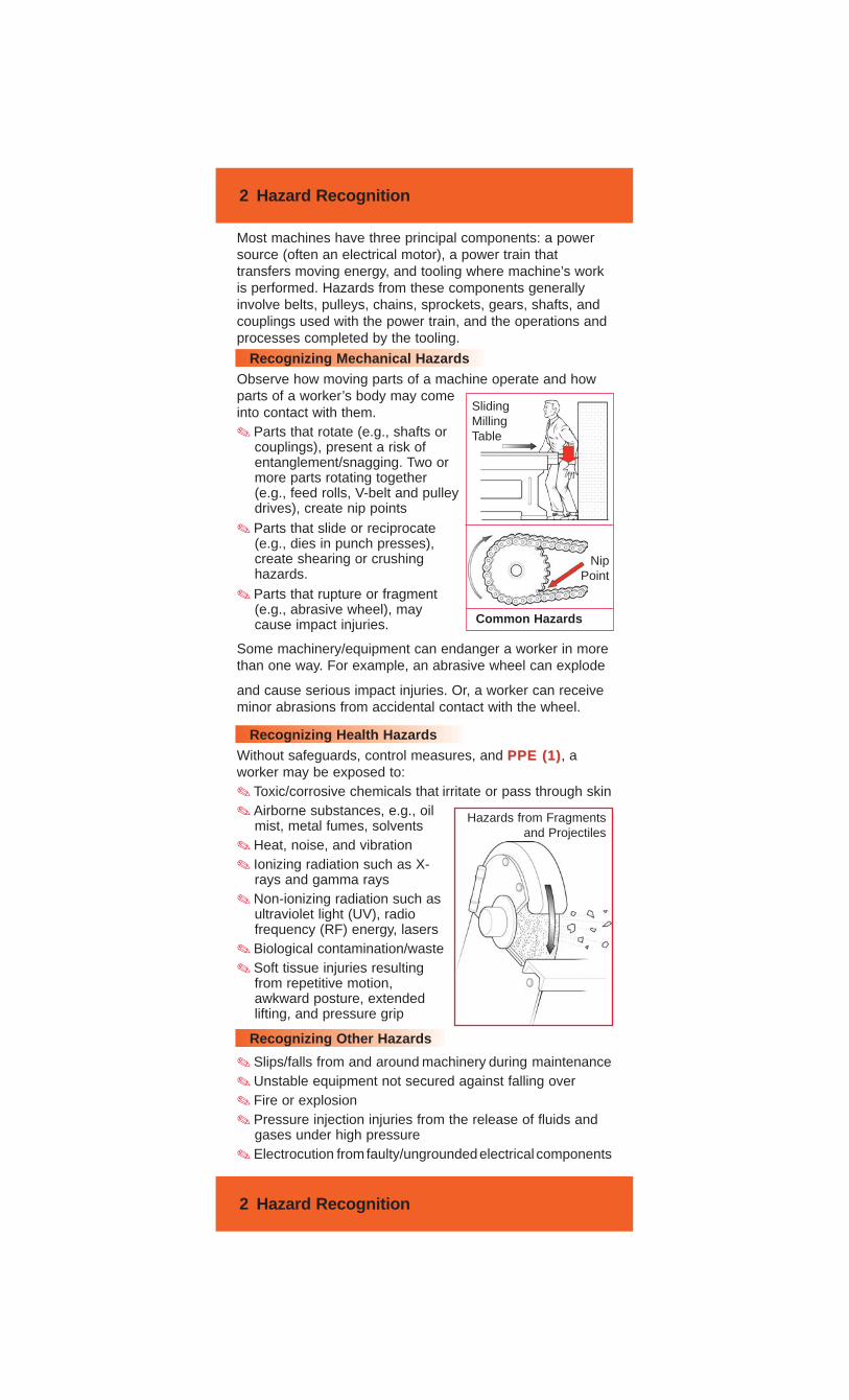
Most machines have three principal components: a powersource (often an electrical motor), a power train thattransfers moving energy, and tooling where machine’s workis performed. Hazards from these components generallyinvolve belts, pulleys, chains, sprockets, gears, shafts, andcouplings used with the power train, and the operations andprocesses completed by the tooling.
Recognizing Mechanical HazardsObserve how moving parts of a machine operate and howparts of a worker’s body may comeinto contact with them. ✎ Parts that rotate (e.g., shafts or
couplings), present a risk ofentanglement/snagging. Two ormore parts rotating together(e.g., feed rolls, V-belt and pulleydrives), create nip points
✎ Parts that slide or reciprocate(e.g., dies in punch presses),create shearing or crushinghazards.
✎ Parts that rupture or fragment(e.g., abrasive wheel), maycause impact injuries.
Some machinery/equipment can endanger a worker in morethan one way. For example, an abrasive wheel can explode
Recognizing Health HazardsWithout safeguards, control measures, and PPE (1)PPE (1), aworker may be exposed to:✎ Toxic/corrosive chemicals that irritate or pass through skin✎ Airborne substances, e.g., oil
mist, metal fumes, solvents✎ Heat, noise, and vibration ✎ Ionizing radiation such as X-
rays and gamma rays✎ Non-ionizing radiation such as
ultraviolet light (UV), radiofrequency (RF) energy, lasers
✎ Biological contamination/waste ✎ Soft tissue injuries resulting
from repetitive motion,awkward posture, extendedlifting, and pressure grip
Recognizing Other Hazards
✎ Slips/falls from and around machinery during maintenance✎ Unstable equipment not secured against falling over✎ Fire or explosion✎ Pressure injection injuries from the release of fluids and
gases under high pressure✎ Electrocution from faulty/ungroundedelectrical components
and cause serious impact injuries. Or, a worker can receiveminor abrasions from accidental contact with the wheel.
Sliding Milling Table
NipPoint
Hazards from Fragmentsand Projectiles
Common Hazards
3 Risk Assessment
3 Risk Assessment
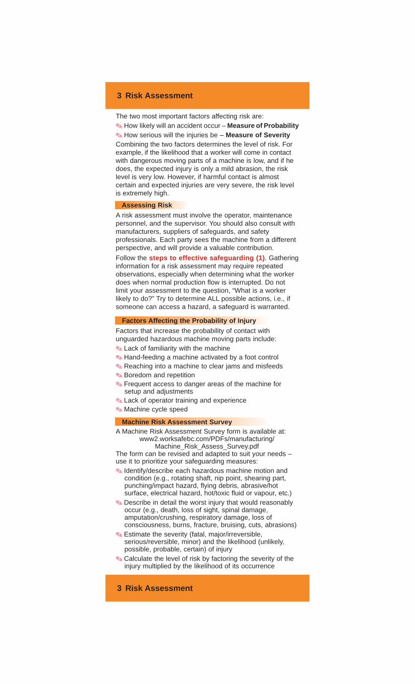
The two most important factors affecting risk are:✎ How likely will an accident occur – Measure of Probability✎ How serious will the injuries be – Measure of SeverityCombining the two factors determines the level of risk. Forexample, if the likelihood that a worker will come in contactwith dangerous moving parts of a machine is low, and if hedoes, the expected injury is only a mild abrasion, the risklevel is very low. However, if harmful contact is almostcertain and expected injuries are very severe, the risk levelis extremely high.
Assessing RiskA risk assessment must involve the operator, maintenancepersonnel, and the supervisor. You should also consult withmanufacturers, suppliers of safeguards, and safetyprofessionals. Each party sees the machine from a differentperspective, and will provide a valuable contribution.
Follow the steps to effective safeguarding (1)steps to effective safeguarding (1). Gatheringinformation for a risk assessment may require repeatedobservations, especially when determining what the workerdoes when normal production flow is interrupted. Do notlimit your assessment to the question, “What is a workerlikely to do?” Try to determine ALL possible actions, i.e., ifsomeone can access a hazard, a safeguard is warranted.
Factors Affecting the Probability of InjuryFactors that increase the probability of contact withunguarded hazardous machine moving parts include:✎ Lack of familiarity with the machine✎ Hand-feeding a machine activated by a foot control✎ Reaching into a machine to clear jams and misfeeds✎ Boredom and repetition✎ Frequent access to danger areas of the machine for
setup and adjustments✎ Lack of operator training and experience✎ Machine cycle speed
Machine Risk Assessment Survey A Machine Risk Assessment Survey form is available at:
www2.worksafebc.com/PDFs/manufacturing/Machine_Risk_Assess_Survey.pdf
The form can be revised and adapted to suit your needs –use it to prioritize your safeguarding measures: ✎ Identify/describe each hazardous machine motion and
condition (e.g., rotating shaft, nip point, shearing part,punching/impact hazard, flying debris, abrasive/hotsurface, electrical hazard, hot/toxic fluid or vapour, etc.)
✎ Describe in detail the worst injury that would reasonablyoccur (e.g., death, loss of sight, spinal damage,amputation/crushing, respiratory damage, loss ofconsciousness, burns, fracture, bruising, cuts, abrasions)
✎ Estimate the severity (fatal, major/irreversible,serious/reversible, minor) and the likelihood (unlikely,possible, probable, certain) of injury
✎ Calculate the level of risk by factoring the severity of theinjury multiplied by the likelihood of its occurrence
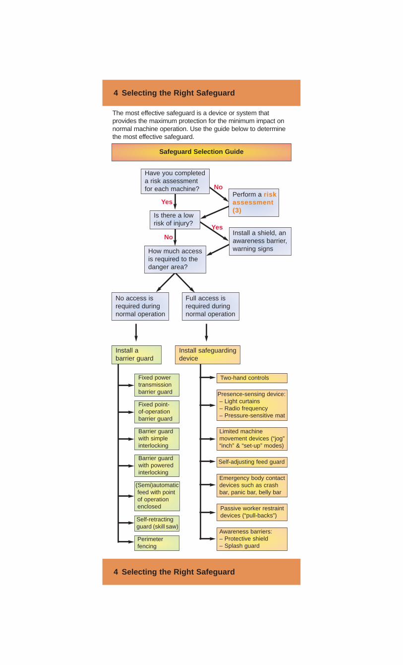
The most effective safeguard is a device or system thatprovides the maximum protection for the minimum impact onnormal machine operation. Use the guide below to determinethe most effective safeguard.
4 Selecting the Right Safeguard
4 Selecting the Right Safeguard
Is there a lowrisk of injury?
Have you completeda risk assessmentfor each machine?
Perform a riskriskassessmentassessment(3)(3)
Install abarrier guard
Full access isrequired duringnormal operation
Install safeguardingdevice
No access isrequired duringnormal operation
Yes
NoYes
No
Safeguard Selection Guide
Fixed powertransmissionbarrier guard
Self-retractingguard (skill saw)
Perimeterfencing
Two-hand controls
Barrier guardwith simpleinterlocking
Fixed point-of-operationbarrier guard
Presence-sensing device:– Light curtains– Radio frequency– Pressure-sensitive mat
Barrier guardwith poweredinterlocking
(Semi)automaticfeed with pointof operationenclosed
Limited machinemovement devices (“jog”“inch” & “set-up” modes)
Emergency body contactdevices such as crashbar, panic bar, belly bar
Self-adjusting feed guard
Passive worker restraintdevices (“pull-backs”)
Awareness barriers:– Protective shield– Splash guard
How much accessis required to thedanger area?
Install a shield, anawareness barrier,warning signs
5 Barrier Guards
5 Barrier Guards
As per the Hierarchy of Safeguarding Controls, barrierguards provide the most effective protection to workers.
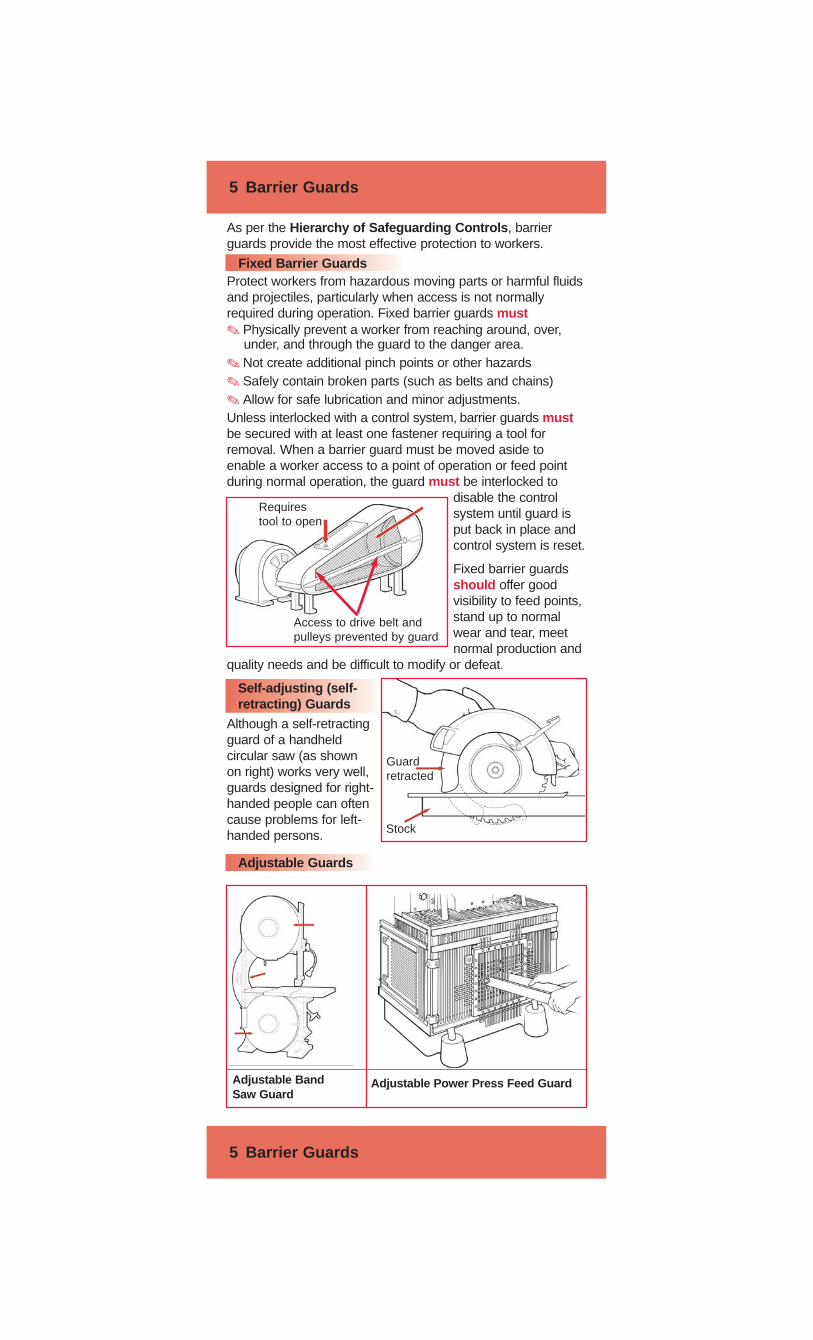
Fixed Barrier GuardsProtect workers from hazardous moving parts or harmful fluidsand projectiles, particularly when access is not normallyrequired during operation. Fixed barrier guards must✎ Physically prevent a worker from reaching around, over,
under, and through the guard to the danger area. ✎ Not create additional pinch points or other hazards✎ Safely contain broken parts (such as belts and chains)✎ Allow for safe lubrication and minor adjustments.Unless interlocked with a control system, barrier guards mustbe secured with at least one fastener requiring a tool forremoval. When a barrier guard must be moved aside toenable a worker access to a point of operation or feed pointduring normal operation, the guard must be interlocked to
disable the controlsystem until guard isput back in place andcontrol system is reset.
Fixed barrier guardsshould offer goodvisibility to feed points,stand up to normalwear and tear, meetnormal production and
quality needs and be difficult to modify or defeat.
Self-adjusting (self-retracting) Guards
Although a self-retractingguard of a handheldcircular saw (as shownon right) works very well,guards designed for right-handed people can oftencause problems for left-handed persons.
Adjustable Guards
Guardretracted
Stock
Adjustable BandSaw Guard
Adjustable Power Press Feed Guard
Access to drive belt andpulleys prevented by guard
Requirestool to open
6 Power Transmission Guards
6 Power Transmission Guards
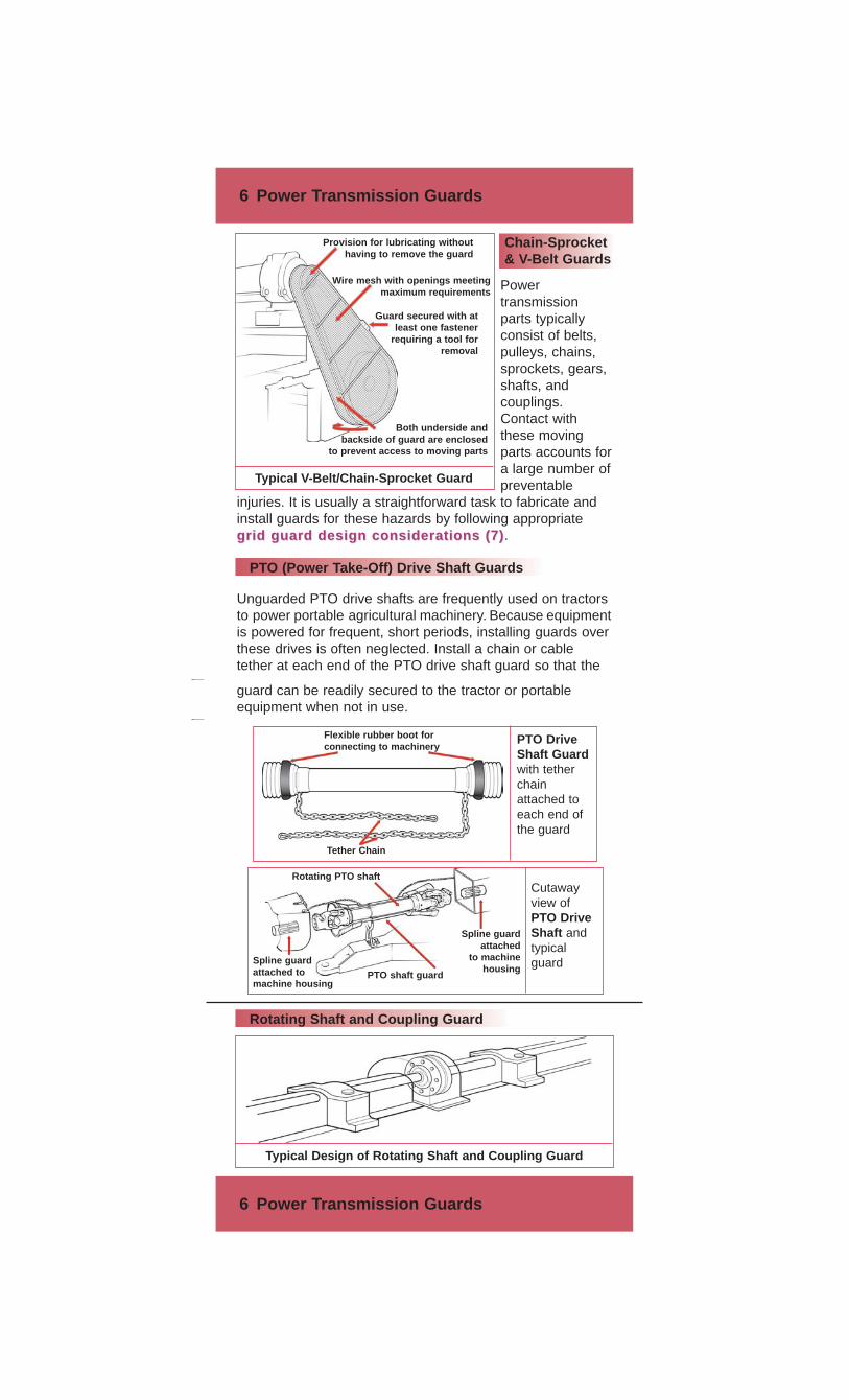
Chain-Sprocket& V-Belt Guards
Powertransmissionparts typicallyconsist of belts,pulleys, chains,sprockets, gears,shafts, andcouplings.Contact withthese movingparts accounts fora large number ofpreventable
injuries. It is usually a straightforward task to fabricate andinstall guards for these hazards by following appropriategrid guard design considerations (7)grid guard design considerations (7).
PTO (Power Take-Off) Drive Shaft Guards
Unguarded PTO drive shafts are frequently used on tractorsto power portable agricultural machinery. Because equipmentis powered for frequent, short periods, installing guards overthese drives is often neglected. Install a chain or cabletether at each end of the PTO drive shaft guard so that the
Rotating Shaft and Coupling Guard
guard can be readily secured to the tractor or portableequipment when not in use.
Wire mesh with openings meetingmaximum requirements
Provision for lubricating withouthaving to remove the guard
Guard secured with atleast one fastener
requiring a tool forremoval
Both underside and backside of guard are enclosed
to prevent access to moving parts
Typical V-Belt/Chain-Sprocket Guard
Flexible rubber boot forconnecting to machinery
Tether Chain
PTO DriveShaft Guardwith tetherchainattached toeach end ofthe guard
Spline guardattached
to machinehousing
Rotating PTO shaftCutawayview ofPTO DriveShaft andtypicalguard
PTO shaft guard
Spline guard attached tomachine housing
Typical Design of Rotating Shaft and Coupling Guard
7 Grid Guard Design Considerations
7 Grid Guard Design Considerations
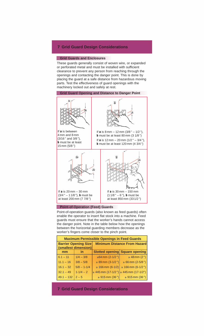
Grid Guards and EnclosuresThese guards generally consist of woven wire, or expandedor perforated metal and must be installed with sufficientclearance to prevent any person from reaching through theopenings and contacting the danger point. This is done byplacing the guard at a safe distance from hazardous movingparts. Test the effectiveness of guard openings with themachinery locked out and safely at rest.
Grid Guard Opening and Distance to Danger Point
Point-of-Operation (Feed) GuardsPoint-of-operation guards (also known as feed guards) oftenenable the operator to insert flat stock into a machine. Feedguards must ensure that the worker’s hands cannot accessthe danger point. Note in the table below how the openingsbetween the horizontal guarding members decrease as theworker’s fingers come closer to the pinch point.
Maximum Permissible Openings in Feed GuardsBarrier Opening Size Minimum Distance From Hazard(smallest dimension)
mm in Slotted opening Square opening
6.1 – 11 1/4 – 3/8 ≥64 mm (2-1/2 '') ≥ 48mm (2 '')
11.1 – 16 3/8 – 5/8 ≥ 89 mm (3-1/2 '') ≥ 66 mm (2-5/8 '')
16.1 – 32 5/8 – 1-1/4 ≥ 166 mm (6-1/2) ≥ 166 mm (6-1/2 '')
32.1 – 49 1-1/4 – 2 ≥ 445 mm (17-1/2 '') ≥ 445 mm (17-1/2'')
49.1 – 132 2 – 5 ≥ 915 mm (36 '') ≥ 915 mm (36 '')
If a is between4 mm and 8 mm(3/16 '' and 3/8 ''),b must be at least15 mm (5/8 '')
If a is 20 mm – 30 mm(3/4 '' – 11/8 ''), b must beat least 200 mm (7 7/8 '')
If a is 30 mm – 150 mm(11/8 '' – 6 ''), b must beat least 850 mm (331/2 '')
If a is 8 mm – 12 mm (3/8 '' – 1/2 ''),b must be at least 80 mm (3 1/8 '')
If a is 12 mm – 20 mm (1/2 '' – 3/4 ''),b must be at least 120 mm (4 3/4 '')
a
aa
a
bb
bb
8 Protective Barriers
8 Protective Barriers
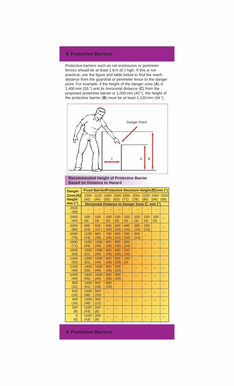
Protective barriers such as rail enclosures or perimeterfences should be at least 1.8 m (6 ') high. If this is notpractical, use the figure and table below to find the reachdistance from the guardrail or perimeter fence to the dangerpoint. For example, if the height of the danger zone (A) is1,400 mm (55 '') and its horizontal distance (C) from theproposed protective barrier is 1,000 mm (40 ''), the height ofthe protective barrier (B) must be at least 1,120 mm (44 '').
Recommended Height of Protective BarrierBased on Distance to Hazard
DangerZone (A) 1000 1120 1400 1600 1800 2000 2200 2400 2500Height (40) (44) (55) (63) (71) (78) (86) (94) (98) mm ('')
2500 – – – – – – – – –(98)
2400 100 100 100 100 100 100 100 100 –(94) (4) (4) (4) (4) (4) (4) (4) (4)
2200 600 600 500 500 400 350 250 – –(86) (24) (24 ) (20) (20) (16) (14) (10)
2000 1100 900 700 600 500 350 – – –(78) (43) (36) (28) (24) (20) (14)
1800 1100 1000 900 900 600 – – – –(71) (43) (40) (36) (36) (24)
1600 1300 1000 900 900 500 – – – –(63) (51) (40) (36) (36) (20)
1400 1300 1000 900 500 100 – – – –(55) (51) (40) (36) (20) (4)
1200 1400 1000 900 500 – – – – –(48) (55) (40) (36) (20)
1000 1400 1000 900 300 – – – – –(40) (55) (40) (36) (20)800 1300 900 600 – – – – – –(32) (51) (36) (24)600 1200 500 – – – – – – –(24) (48) (20)400 1200 300 – – – – – – –(16) (48) (12)200 1100 200 – – – – – – –(8) (43) (8)
0 1100 200 – – – – – – –(0) (43) (8)
Fixed Barrier/Protective Structure Height (B)mm ('')
Horizontal Distance to Danger Zone C, mm ('')
Danger Point

Legal Background Information
Topics discussed in this infoflip, and other relatedissues, are based on the following legislation:
Safeguarding: Operational Health and SafetyRegulation (OHSR), Part 12
“Safeguarding protects workers whenmachinery or equipment is in operation”
Training & Supervision: Workers CompensationAct, Sections 115-17
“Training and Supervision is needed for allaspects of equipment operation andmaintenance”.
Lockout: Operational Health and SafetyRegulation (OHSR), Part 10
“Lockout protects workers when machinery orequipment is shut down for maintenance”.
The OHSR, associated policies and guidelines, andexcerpts/summaries of the Workers CompensationAct are available on www.worksafebc.com. Somepublications may also be available in print:
(604) 232-9704 or toll-free 1-866-319-9704
9 Two-Hand Controls and Trips
9 Two-Hand Controls and Trips
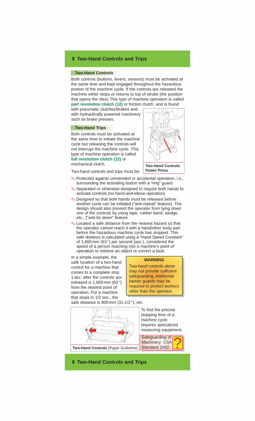
Two-Hand ControlsBoth controls (buttons, levers, sensors) must be activated atthe same time and kept engaged throughout the hazardousportion of the machine cycle. If the controls are released themachine either stops or returns to top of stroke (the positionthat opens the dies).This type of machine operation is calledpart revolution clutch (12) or friction clutch, and is foundwith pneumatic clutches/brakes andwith hydraulically powered machinerysuch as brake presses.
Two-Hand TripsBoth controls must be activated atthe same time to initiate the machinecycle but releasing the controls willnot interrupt the machine cycle. Thistype of machine operation is calledfull revolution clutch (12) ormechanical clutch.
Two-hand controls and trips must be:
✎ Protected against unintended or accidental operation, i.e.,surrounding the activating button with a “ring” guard
✎ Separated or otherwise designed to require both hands toactivate controls (no hand-and-elbow operation)
✎ Designed so that both hands must be released beforeanother cycle can be initiated (“anti-repeat” feature). Thedesign should also prevent the operator from tying downone of the controls by using tape, rubber band, wedge,etc., (“anti-tie down” feature
✎ Located a safe distance from the nearest hazard so thatthe operator cannot reach it with a hand/other body partbefore the hazardous machine cycle has stopped. Thissafe distance is calculated using a “Hand Speed Constant”of 1,600 mm (63 '') per second (sec.), considered thespeed of a person reaching into a machine’s point ofoperation to retrieve an object or correct a fault.
In a simple example, thesafe location of a two-handcontrol for a machine thatcomes to a complete stop1 sec. after the controls arereleased is 1,600 mm (63 '')from the nearest point ofoperation. For a machinethat stops in 1/2 sec., thesafe distance is 800 mm (31-1/2 ''), etc.
To find the precisestopping time of amachine cyclerequires specializedmeasuring equipment.
Two-Hand ControlsPower Press
WARNINGTwo-hand controls alonemay not provide sufficientsafeguarding. Additionalbarrier guards may berequired to protect workersother than the operator.
Two-Hand Controls (Paper Guillotine)
Safeguarding ofMachinery: CSAStandard Z432 ?
10 Presence-Sensing Devices
10 Presence-Sensing Devices
Devices such as light curtains, proximity sensors, and safetymats do not prevent access to hazardous points of operation.They simply prevent dangerous machine motion by sendinga stop signal if any part of a worker’s body is in the dangerarea when a machine cycle is initiated. Choose this type ofsafeguard when frequent access is needed for loading partsand making adjustments, and physical guarding is restrictive.There are many technical factors, such as machine controlreliability and safety distance, that affect the proper selectionand positioning of presence-sensing devices.
Presence-Sensing Device Limitations✎ They may not provide sufficient safeguarding when used
alone; additional barrier guarding may be required✎ Do not use for machines with a full-revolution clutch✎ Review the requirements of relevant standards before
installing a presence-sensing device✎ Use only during production, not as substitute for lockout.
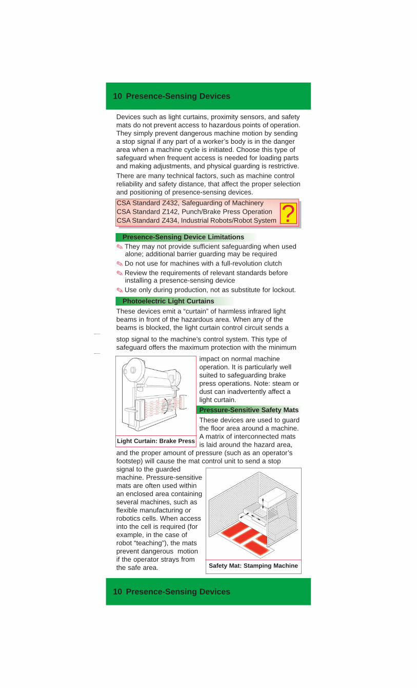
Photoelectric Light CurtainsThese devices emit a “curtain” of harmless infrared lightbeams in front of the hazardous area. When any of thebeams is blocked, the light curtain control circuit sends a
stop signal to the machine’s control system. This type ofsafeguard offers the maximum protection with the minimum
impact on normal machineoperation. It is particularly wellsuited to safeguarding brakepress operations. Note: steam ordust can inadvertently affect alight curtain.
Pressure-Sensitive Safety MatsThese devices are used to guardthe floor area around a machine.A matrix of interconnected matsis laid around the hazard area,
and the proper amount of pressure (such as an operator’sfootstep) will cause the mat control unit to send a stopsignal to the guardedmachine. Pressure-sensitivemats are often used withinan enclosed area containingseveral machines, such asflexible manufacturing orrobotics cells. When accessinto the cell is required (forexample, in the case ofrobot “teaching”), the matsprevent dangerous motionif the operator strays fromthe safe area. Safety Mat: Stamping Machine
Light Curtain: Brake Press
CSA Standard Z432, Safeguarding of MachineryCSA Standard Z142, Punch/Brake Press OperationCSA Standard Z434, Industrial Robots/Robot System ?
11 Safety Interlocks
11 Safety Interlocks
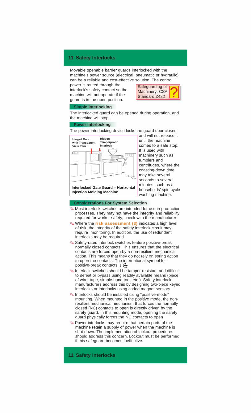
Movable openable barrier guards interlocked with themachine’s power source (electrical, pneumatic or hydraulic)can be a reliable and cost-effective solution. The controlpower is routed through theinterlock’s safety contact so themachine will not operate if theguard is in the open position.
Simple InterlockingThe interlocked guard can be opened during operation, andthe machine will stop.
Power InterlockingThe power interlocking device locks the guard door closed
and will not release ituntil the machinecomes to a safe stop.It is used withmachinery such astumblers andcentrifuges, where thecoasting-down timemay take severalseconds to severalminutes, such as ahouseholds’ spin cyclewashing machine.
Considerations For System Selection✎ Most interlock switches are intended for use in production
processes. They may not have the integrity and reliabilityrequired for worker safety; check with the manufacturer
✎ Where the risk assessment (3)risk assessment (3) indicates a high levelof risk, the integrity of the safety interlock circuit mayrequire monitoring. In addition, the use of redundantinterlocks may be required
✎ Safety-rated interlock switches feature positive-breaknormally closed contacts. This ensures that the electricalcontacts are forced open by a non-resilient mechanicalaction. This means that they do not rely on spring actionto open the contacts. The international symbol forpositive-break contacts is
✎ Interlock switches should be tamper-resistant and difficultto defeat or bypass using readily available means (pieceof wire, tape, simple hand tool, etc.). Safety interlockmanufacturers address this by designing two-piece keyedinterlocks or interlocks using coded magnet sensors
✎ Interlocks should be installed using “positive-mode”mounting. When mounted in the positive mode, the non-resilient mechanical mechanism that forces the normallyclosed (NC) contacts to open is directly driven by thesafety guard. In this mounting mode, opening the safetyguard physically forces the NC contacts to open
✎ Power interlocks may require that certain parts of themachine retain a supply of power when the machine isshut down. The implementation of lockout proceduresshould address this concern. Lockout must be performedif this safeguard becomes ineffective.
➔
Interlocked Gate Guard – HorizontalInjection Molding Machine
Hinged Doorwith TransparentView Panel
HiddenTamperproofInterlock
Safeguarding ofMachinery: CSAStandard Z432 ?
12 Movable Gates
12 Movable Gates
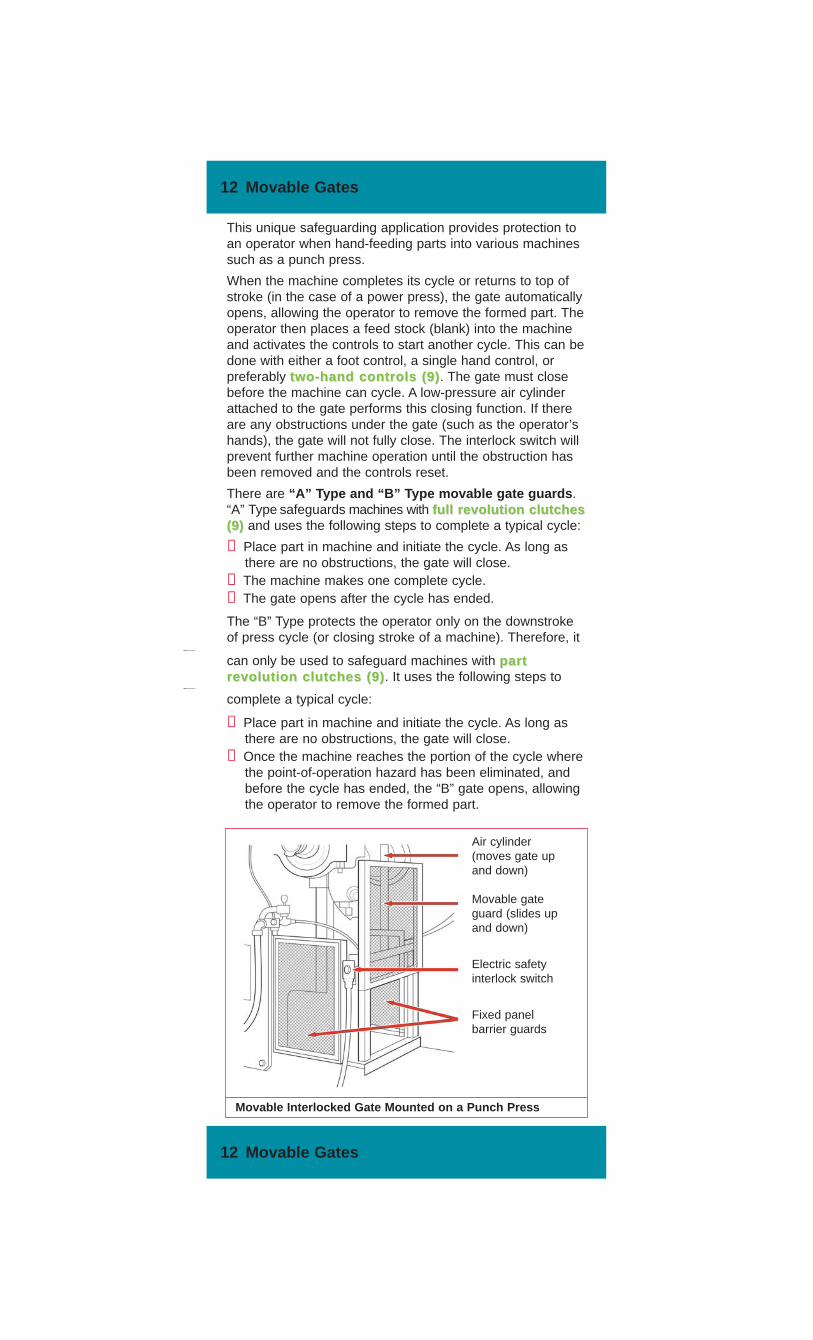
complete a typical cycle:
➀ Place part in machine and initiate the cycle. As long asthere are no obstructions, the gate will close.
➁ Once the machine reaches the portion of the cycle wherethe point-of-operation hazard has been eliminated, andbefore the cycle has ended, the “B” gate opens, allowingthe operator to remove the formed part.
can only be used to safeguard machines with partpartrevolution clutches (9)revolution clutches (9). It uses the following steps to
This unique safeguarding application provides protection toan operator when hand-feeding parts into various machinessuch as a punch press.
When the machine completes its cycle or returns to top ofstroke (in the case of a power press), the gate automaticallyopens, allowing the operator to remove the formed part. Theoperator then places a feed stock (blank) into the machineand activates the controls to start another cycle. This can bedone with either a foot control, a single hand control, orpreferably two-hand controls (9)two-hand controls (9). The gate must closebefore the machine can cycle. A low-pressure air cylinderattached to the gate performs this closing function. If thereare any obstructions under the gate (such as the operator’shands), the gate will not fully close. The interlock switch willprevent further machine operation until the obstruction hasbeen removed and the controls reset.
There are “A” Type and “B” Type movable gate guards.“A” Type safeguards machines with full revolution clutchesfull revolution clutches(9)(9) and uses the following steps to complete a typical cycle:
➀ Place part in machine and initiate the cycle. As long asthere are no obstructions, the gate will close.
➁ The machine makes one complete cycle.➂ The gate opens after the cycle has ended.
The “B” Type protects the operator only on the downstrokeof press cycle (or closing stroke of a machine). Therefore, it
Movable Interlocked Gate Mounted on a Punch Press
Air cylinder(moves gate upand down)
Movable gateguard (slides upand down)
Electric safetyinterlock switch
Fixed panelbarrier guards
13 Pull Wires – Trip Wires – Contact Bumpers
13 Pull Wires – Trip Wires – Contact Bumpers
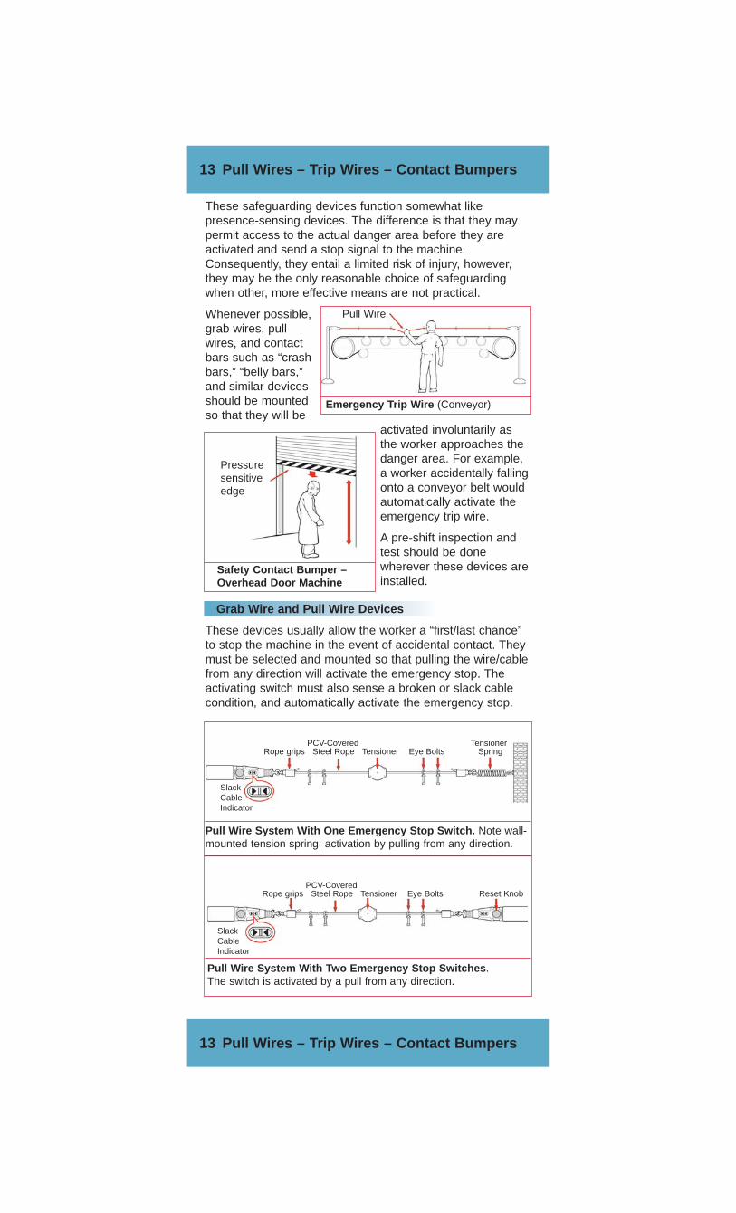
These safeguarding devices function somewhat likepresence-sensing devices. The difference is that they maypermit access to the actual danger area before they areactivated and send a stop signal to the machine.Consequently, they entail a limited risk of injury, however,they may be the only reasonable choice of safeguardingwhen other, more effective means are not practical.
Whenever possible,grab wires, pullwires, and contactbars such as “crashbars,” “belly bars,”and similar devicesshould be mountedso that they will be
activated involuntarily asthe worker approaches thedanger area. For example,a worker accidentally fallingonto a conveyor belt wouldautomatically activate theemergency trip wire.
A pre-shift inspection andtest should be donewherever these devices areinstalled.
Grab Wire and Pull Wire Devices
These devices usually allow the worker a “first/last chance”to stop the machine in the event of accidental contact. Theymust be selected and mounted so that pulling the wire/cablefrom any direction will activate the emergency stop. Theactivating switch must also sense a broken or slack cablecondition, and automatically activate the emergency stop.
Pull Wire
Emergency Trip Wire (Conveyor)
Safety Contact Bumper –Overhead Door Machine
Pressuresensitiveedge
Pull Wire System With Two Emergency Stop Switches.The switch is activated by a pull from any direction.
SlackCableIndicator
SlackCableIndicator
PCV-CoveredRope grips Steel Rope Tensioner Eye Bolts Reset Knob
PCV-Covered TensionerRope grips Steel Rope Tensioner Eye Bolts Spring
Pull Wire System With One Emergency Stop Switch. Note wall-mounted tension spring; activation by pulling from any direction.
14 Shields – Awareness Barriers
14 Shields – Awareness Barriers
Shields
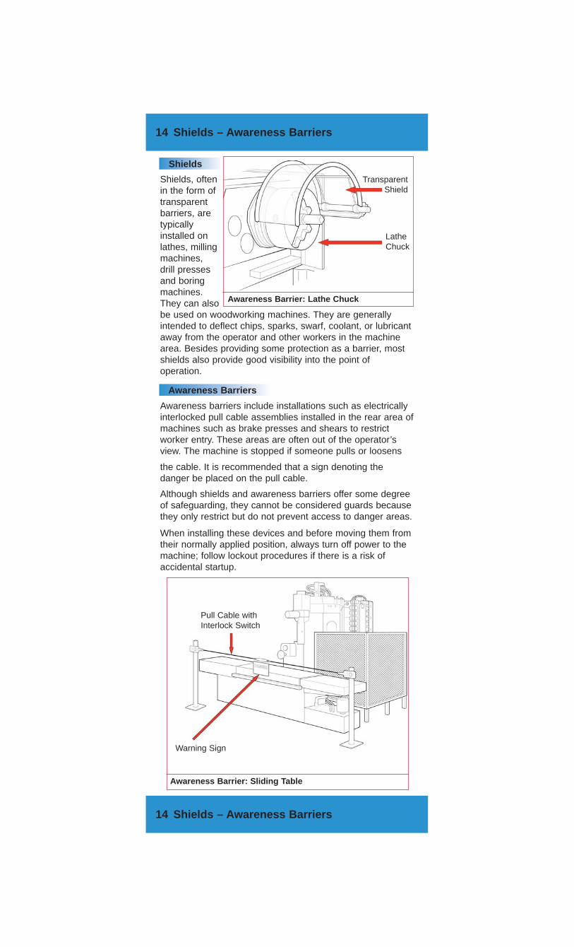
Shields, oftenin the form oftransparentbarriers, aretypicallyinstalled onlathes, millingmachines,drill pressesand boringmachines.They can alsobe used on woodworking machines. They are generallyintended to deflect chips, sparks, swarf, coolant, or lubricantaway from the operator and other workers in the machinearea. Besides providing some protection as a barrier, mostshields also provide good visibility into the point ofoperation.
Awareness Barriers
Awareness barriers include installations such as electricallyinterlocked pull cable assemblies installed in the rear area ofmachines such as brake presses and shears to restrictworker entry. These areas are often out of the operator’sview. The machine is stopped if someone pulls or loosens
Although shields and awareness barriers offer some degreeof safeguarding, they cannot be considered guards becausethey only restrict but do not prevent access to danger areas.
When installing these devices and before moving them fromtheir normally applied position, always turn off power to themachine; follow lockout procedures if there is a risk ofaccidental startup.
the cable. It is recommended that a sign denoting thedanger be placed on the pull cable.
TransparentShield
LatheChuck
Awareness Barrier: Lathe Chuck
Pull Cable withInterlock Switch
Warning Sign
Awareness Barrier: Sliding Table
15 Safeguarding by Location
15 Safeguarding by Location
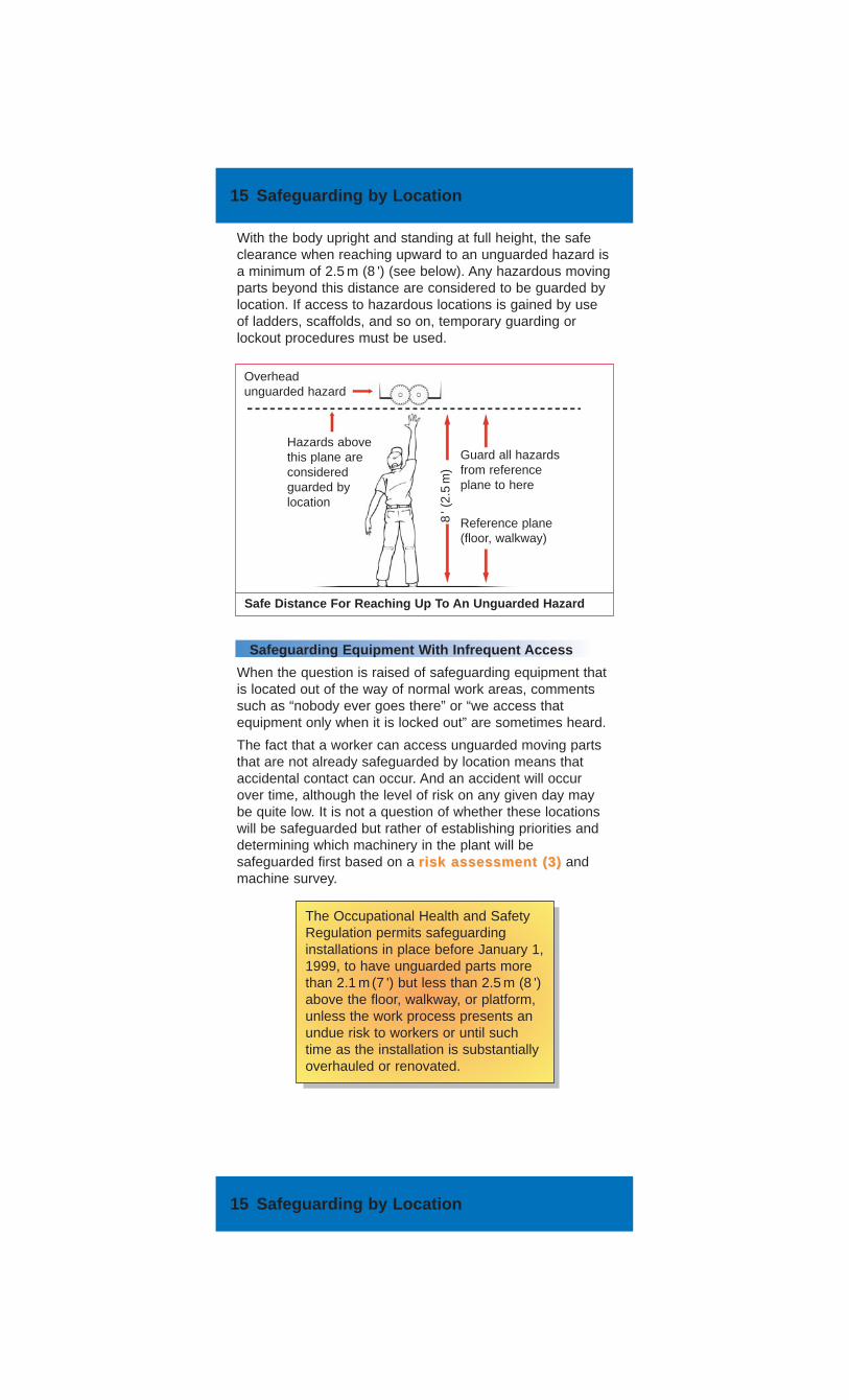
With the body upright and standing at full height, the safeclearance when reaching upward to an unguarded hazard isa minimum of 2.5 m (8 ') (see below). Any hazardous movingparts beyond this distance are considered to be guarded bylocation. If access to hazardous locations is gained by useof ladders, scaffolds, and so on, temporary guarding orlockout procedures must be used.
Safeguarding Equipment With Infrequent Access
When the question is raised of safeguarding equipment thatis located out of the way of normal work areas, commentssuch as “nobody ever goes there” or “we access thatequipment only when it is locked out” are sometimes heard.
The fact that a worker can access unguarded moving partsthat are not already safeguarded by location means thataccidental contact can occur. And an accident will occurover time, although the level of risk on any given day maybe quite low. It is not a question of whether these locationswill be safeguarded but rather of establishing priorities anddetermining which machinery in the plant will besafeguarded first based on a risk assessment (3)risk assessment (3) andmachine survey.
The Occupational Health and SafetyRegulation permits safeguardinginstallations in place before January 1,1999, to have unguarded parts morethan 2.1 m(7 ') but less than 2.5 m (8 ')above the floor, walkway, or platform,unless the work process presents anundue risk to workers or until suchtime as the installation is substantiallyoverhauled or renovated.
Safe Distance For Reaching Up To An Unguarded Hazard
Overheadunguarded hazard
Hazards abovethis plane areconsideredguarded bylocation
Guard all hazardsfrom referenceplane to here
Reference plane(floor, walkway)
8' (
2.5
m)
16 E-Stops
The following requirements apply to all E-stop installations:
✎ Mushroom-shaped and red in colour
✎ Located within immediate and unimpeded reach of theoperator or other persons directly affected by themachine operation
✎ Designed to allow immediate activation with any part ofthe body (no ring guards or recessed position)
✎ Requires a manual push to activate and a manual pull toreset; remains in the depressed position when activated(not a “hold-to-run” type switch)
✎ A check for safe machine operation is required before anE-stop is reset
✎ Must be hard-wired into the control circuit to allow themagnetic coil to drop out (cannot be routed through aProgrammable LogicController [PLC] except formonitoring purposes)
✎ The machine must notrestart merely by pulling outand resetting the E-stop. Asecond, independentcontrol must also beactivated before themachine will restart.
16 E-Stops
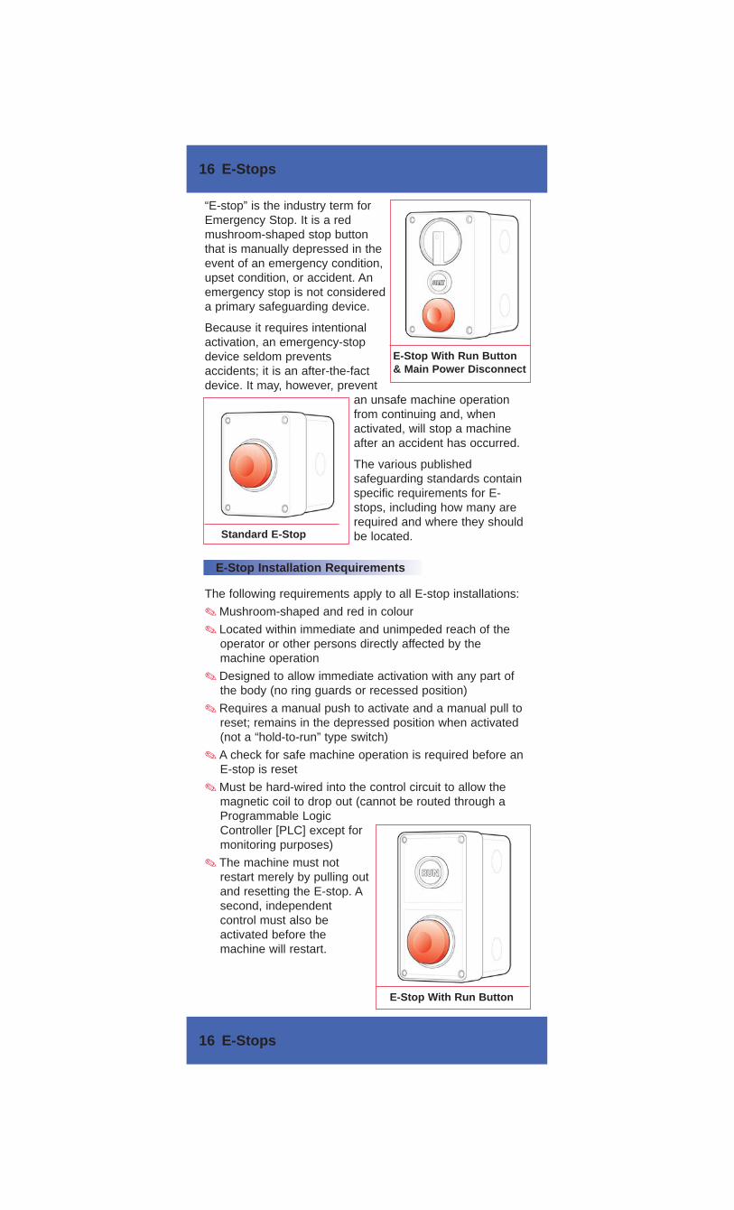
“E-stop” is the industry term forEmergency Stop. It is a redmushroom-shaped stop buttonthat is manually depressed in theevent of an emergency condition,upset condition, or accident. Anemergency stop is not considereda primary safeguarding device.
Because it requires intentionalactivation, an emergency-stopdevice seldom preventsaccidents; it is an after-the-factdevice. It may, however, prevent
an unsafe machine operationfrom continuing and, whenactivated, will stop a machineafter an accident has occurred.
The various publishedsafeguarding standards containspecific requirements for E-stops, including how many arerequired and where they shouldbe located.
E-Stop Installation Requirements
E-Stop With Run Button& Main Power Disconnect
Standard E-Stop
E-Stop With Run Button