Embed Size (px)
Citation preview

Safe & Secure Series Electric Actuator with Internal Battery Back-up
Installation, Operation & Maintenance Manual
TELEPHONE: +1-859-727-7890
TOLL FREE: +1-800-662-9424
FAX: +1-859-727-4070
E-MAIL: [email protected]
SHIPPING ADDRESS: 6810 POWERLINE DR.-FLORENCE, KY. 41042
VISIT OUR WEBSITE AT WWW.INDELAC.COM
Safe & Secure Series Electric Actuator with Internal Battery Back-up Installation, Operation & Maintenance Manual
Page 2
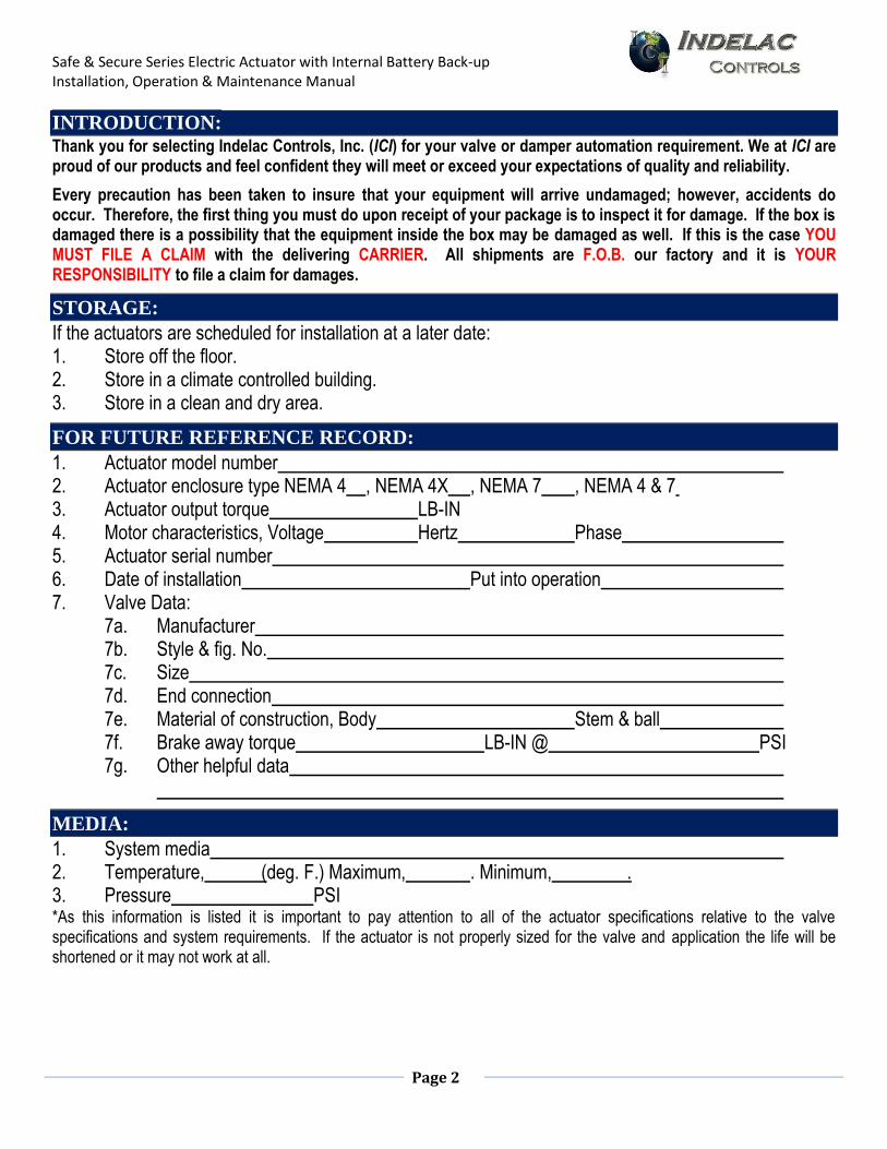
INTRODUCTION: Thank you for selecting Indelac Controls, Inc. (ICI) for your valve or damper automation requirement. We at ICI are proud of our products and feel confident they will meet or exceed your expectations of quality and reliability.
Every precaution has been taken to insure that your equipment will arrive undamaged; however, accidents do occur. Therefore, the first thing you must do upon receipt of your package is to inspect it for damage. If the box is damaged there is a possibility that the equipment inside the box may be damaged as well. If this is the case YOU MUST FILE A CLAIM with the delivering CARRIER. All shipments are F.O.B. our factory and it is YOUR RESPONSIBILITY to file a claim for damages.
STORAGE:
If the actuators are scheduled for installation at a later date: 1. Store off the floor. 2. Store in a climate controlled building. 3. Store in a clean and dry area.
FOR FUTURE REFERENCE RECORD:
1. Actuator model number 2. Actuator enclosure type NEMA 4 , NEMA 4X , NEMA 7 , NEMA 4 & 7 3. Actuator output torque LB-IN 4. Motor characteristics, Voltage Hertz Phase 5. Actuator serial number 6. Date of installation Put into operation 7. Valve Data: 7a. Manufacturer 7b. Style & fig. No. 7c. Size 7d. End connection 7e. Material of construction, Body Stem & ball 7f. Brake away torque LB-IN @ PSI 7g. Other helpful data
MEDIA:
1. System media 2. Temperature, (deg. F.) Maximum, . Minimum, . 3. Pressure PSI *As this information is listed it is important to pay attention to all of the actuator specifications relative to the valve specifications and system requirements. If the actuator is not properly sized for the valve and application the life will be shortened or it may not work at all.
Safe & Secure Series Electric Actuator with Internal Battery Back-up Installation, Operation & Maintenance Manual
Page 3
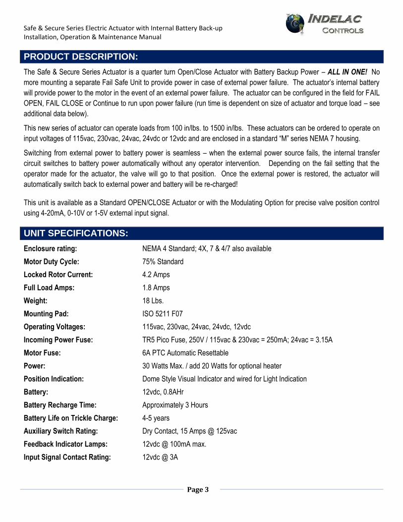
PRODUCT DESCRIPTION:
The Safe & Secure Series Actuator is a quarter turn Open/Close Actuator with Battery Backup Power – ALL IN ONE! No
more mounting a separate Fail Safe Unit to provide power in case of external power failure. The actuator’s internal battery
will provide power to the motor in the event of an external power failure. The actuator can be configured in the field for FAIL
OPEN, FAIL CLOSE or Continue to run upon power failure (run time is dependent on size of actuator and torque load – see
additional data below).
This new series of actuator can operate loads from 100 in/lbs. to 1500 in/lbs. These actuators can be ordered to operate on
input voltages of 115vac, 230vac, 24vac, 24vdc or 12vdc and are enclosed in a standard “M” series NEMA 7 housing.
Switching from external power to battery power is seamless – when the external power source fails, the internal transfer
circuit switches to battery power automatically without any operator intervention. Depending on the fail setting that the
operator made for the actuator, the valve will go to that position. Once the external power is restored, the actuator will
automatically switch back to external power and battery will be re-charged!
This unit is available as a Standard OPEN/CLOSE Actuator or with the Modulating Option for precise valve position control
using 4-20mA, 0-10V or 1-5V external input signal.
UNIT SPECIFICATIONS:
Enclosure rating: NEMA 4 Standard; 4X, 7 & 4/7 also available
Motor Duty Cycle: 75% Standard
Locked Rotor Current: 4.2 Amps
Full Load Amps: 1.8 Amps
Weight: 18 Lbs.
Mounting Pad: ISO 5211 F07
Operating Voltages: 115vac, 230vac, 24vac, 24vdc, 12vdc
Incoming Power Fuse: TR5 Pico Fuse, 250V / 115vac & 230vac = 250mA; 24vac = 3.15A
Motor Fuse: 6A PTC Automatic Resettable
Power: 30 Watts Max. / add 20 Watts for optional heater
Position Indication: Dome Style Visual Indicator and wired for Light Indication
Battery: 12vdc, 0.8AHr
Battery Recharge Time: Approximately 3 Hours
Battery Life on Trickle Charge: 4-5 years
Auxiliary Switch Rating: Dry Contact, 15 Amps @ 125vac
Feedback Indicator Lamps: 12vdc @ 100mA max.
Input Signal Contact Rating: 12vdc @ 3A
Safe & Secure Series Electric Actuator with Internal Battery Back-up Installation, Operation & Maintenance Manual
Page 4
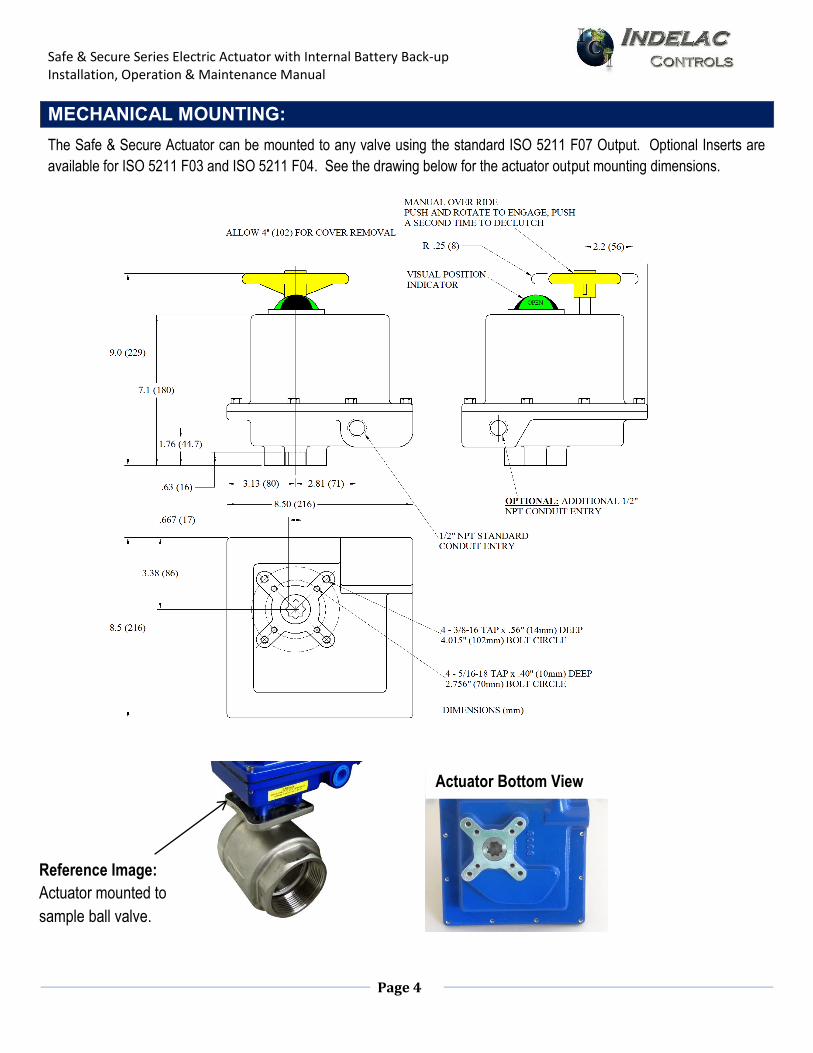
MECHANICAL MOUNTING:
The Safe & Secure Actuator can be mounted to any valve using the standard ISO 5211 F07 Output. Optional Inserts are available for ISO 5211 F03 and ISO 5211 F04. See the drawing below for the actuator output mounting dimensions.
Reference Image: Actuator mounted to sample ball valve.
Actuator Bottom View
Safe & Secure Series Electric Actuator with Internal Battery Back-up Installation, Operation & Maintenance Manual
Page 5
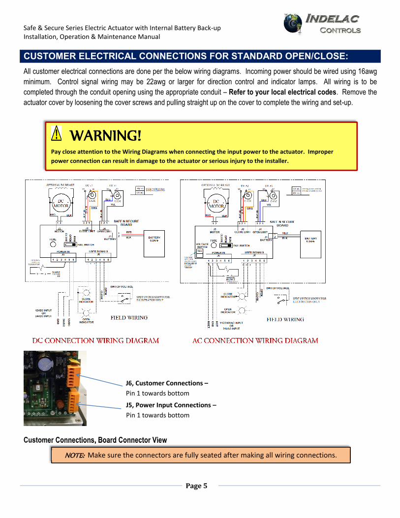
CUSTOMER ELECTRICAL CONNECTIONS FOR STANDARD OPEN/CLOSE:
All customer electrical connections are done per the below wiring diagrams. Incoming power should be wired using 16awg minimum. Control signal wiring may be 22awg or larger for direction control and indicator lamps. All wiring is to be completed through the conduit opening using the appropriate conduit – Refer to your local electrical codes. Remove the actuator cover by loosening the cover screws and pulling straight up on the cover to complete the wiring and set-up.
Customer Connections, Board Connector View
Customer Connections, Board Connector View
NOTE: Make sure the connectors are fully seated after making all wiring connections.
J6, Customer Connections –
Pin 1 towards bottom
J5, Power Input Connections –
Pin 1 towards bottom
WARNING!
Pay close attention to the Wiring Diagrams when connecting the input power to the actuator. Improper
power connection can result in damage to the actuator or serious injury to the installer.
Safe & Secure Series Electric Actuator with Internal Battery Back-up Installation, Operation & Maintenance Manual
Page 6
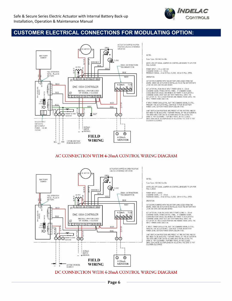
CUSTOMER ELECTRICAL CONNECTIONS FOR MODULATING OPTION:
Safe & Secure Series Electric Actuator with Internal Battery Back-up Installation, Operation & Maintenance Manual
Page 7
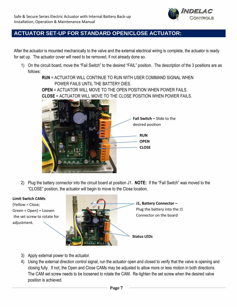
Limit Switch CAMs
(Yellow = Close;
Green = Open) – Loosen
the set screw to rotate for
adjustment.
ACTUATOR SET-UP FOR STANDARD OPEN/CLOSE ACTUATOR:
After the actuator is mounted mechanically to the valve and the external electrical wiring is complete, the actuator is ready
for set up. The actuator cover will need to be removed, if not already done so.
1) On the circuit board, move the “Fail Switch” to the desired “FAIL” position. The description of the 3 positions are as
follows:
RUN = ACTUATOR WILL CONTINUE TO RUN WITH USER COMMAND SIGNAL WHEN
POWER FAILS UNTIL THE BATTERY DIES.
OPEN = ACTUATOR WILL MOVE TO THE OPEN POSITION WHEN POWER FAILS.
CLOSE = ACTUATOR WILL MOVE TO THE CLOSE POSITION WHEN POWER FAILS.
2) Plug the battery connector into the circuit board at position J1. NOTE: If the “Fail Switch” was moved to the
“CLOSE” position, the actuator will begin to move to the Close location.
3) Apply external power to the actuator.
4) Using the external direction control signal, run the actuator open and closed to verify that the valve is opening and
closing fully. If not, the Open and Close CAMs may be adjusted to allow more or less motion in both directions.
The CAM set screw needs to be loosened to rotate the CAM. Re-tighten the set screw when the desired valve
position is achieved.
Status LEDs
RUN
OPEN
CLOSE
Fail Switch – Slide to the
desired position
J1, Battery Connector –
Plug the battery into the J1
Connector on the board
Safe & Secure Series Electric Actuator with Internal Battery Back-up Installation, Operation & Maintenance Manual
Page 8
Limit Switch CAMs
(Yellow = Close;
Green = Open) –Do not
need adjustment.
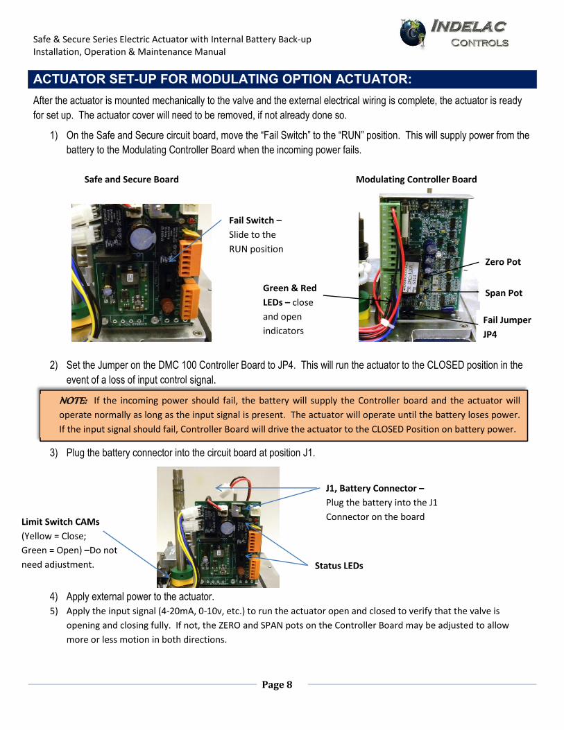
ACTUATOR SET-UP FOR MODULATING OPTION ACTUATOR:
After the actuator is mounted mechanically to the valve and the external electrical wiring is complete, the actuator is ready for set up. The actuator cover will need to be removed, if not already done so.
1) On the Safe and Secure circuit board, move the “Fail Switch” to the “RUN” position. This will supply power from the
battery to the Modulating Controller Board when the incoming power fails.
2) Set the Jumper on the DMC 100 Controller Board to JP4. This will run the actuator to the CLOSED position in the event of a loss of input control signal.
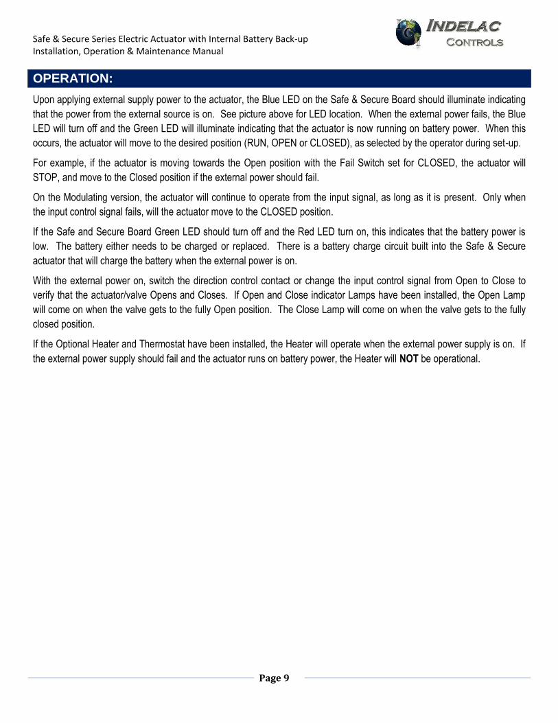
3) Plug the battery connector into the circuit board at position J1.
4) Apply external power to the actuator. 5) Apply the input signal (4-20mA, 0-10v, etc.) to run the actuator open and closed to verify that the valve is
opening and closing fully. If not, the ZERO and SPAN pots on the Controller Board may be adjusted to allow
more or less motion in both directions.
Status LEDs
Fail Switch –
Slide to the
RUN position
J1, Battery Connector –
Plug the battery into the J1
Connector on the board
Green & Red
LEDs – close
and open
indicators
Zero Pot
Span Pot
Fail Jumper
JP4
Safe and Secure Board Modulating Controller Board
event of a loss of input signal.
NOTE: If the incoming power should fail, the battery will supply the Controller board and the actuator will
operate normally as long as the input signal is present. The actuator will operate until the battery loses power.
If the input signal should fail, Controller Board will drive the actuator to the CLOSED Position on battery power.
Safe & Secure Series Electric Actuator with Internal Battery Back-up Installation, Operation & Maintenance Manual
Page 9
OPERATION:
Upon applying external supply power to the actuator, the Blue LED on the Safe & Secure Board should illuminate indicating
that the power from the external source is on. See picture above for LED location. When the external power fails, the Blue
LED will turn off and the Green LED will illuminate indicating that the actuator is now running on battery power. When this
occurs, the actuator will move to the desired position (RUN, OPEN or CLOSED), as selected by the operator during set-up.
For example, if the actuator is moving towards the Open position with the Fail Switch set for CLOSED, the actuator will
STOP, and move to the Closed position if the external power should fail.
On the Modulating version, the actuator will continue to operate from the input signal, as long as it is present. Only when
the input control signal fails, will the actuator move to the CLOSED position.
If the Safe and Secure Board Green LED should turn off and the Red LED turn on, this indicates that the battery power is
low. The battery either needs to be charged or replaced. There is a battery charge circuit built into the Safe & Secure
actuator that will charge the battery when the external power is on.
With the external power on, switch the direction control contact or change the input control signal from Open to Close to
verify that the actuator/valve Opens and Closes. If Open and Close indicator Lamps have been installed, the Open Lamp
will come on when the valve gets to the fully Open position. The Close Lamp will come on when the valve gets to the fully
closed position.
If the Optional Heater and Thermostat have been installed, the Heater will operate when the external power supply is on. If
the external power supply should fail and the actuator runs on battery power, the Heater will NOT be operational.
Safe & Secure Series Electric Actuator with Internal Battery Back-up Installation, Operation & Maintenance Manual
Page 10
TESTING AND TROUBLESHOOTING: Battery Condition Test
1) Remove the external power and verify that the Green LED illuminates. If it does, then the battery is properly charged and ready for operation.
2) If the Red LED illuminates, the battery is low. 3) Apply external power to the actuator and verify that the Blue LED illuminates. 4) Wait 1-2 hours and repeat by removing the external power. 5) If the Green LED illuminates, the battery is good and is charged. 6) If the Red LED illuminates, the battery is bad and needs to be replaced.
Power Test 1) Apply external power to the actuator. The Blue LED should illuminate. 2) If there is no Blue LED, check that the incoming power is terminated & the breaker is on. 3) Next, verify that the power is correctly connected to the actuator and the wires are tight in the input connector. 4) On the AC versions, make sure that the 115/230V switch is in the proper position for the appropriate power input. 5) On the DC versions, verify that either the 24V or 12V is connected to the appropriate terminal. 6) If still no Blue LED, check the on board fuse (AC versions only) in the Safe & Secure Actuator. 7) If the fuse is blown, replace the fuse. 8) If the fuse is good, the circuit board is bad and needs to be replaced.
WARNING! Pay close attention to the Wiring Diagrams when connecting the input power to the
actuator. Improper power connection can result in damage to the actuator or serious
injury to the installer.
Safe & Secure Series Electric Actuator with Internal Battery Back-up Installation, Operation & Maintenance Manual
Page 11
DUTY CYCLE:
ICI actuators rated 100 LB-IN up to 1500 LB-IN output torque are rated for 25% duty cycle at 100% ambient temperature at rated torque (75% duty cycle motors are available upon request). Actuators rated for 2000 LB-IN output torque and greater are rated for continuous duty. All direct current (dc) motors are rated for 75% duty cycle.
THERMAL OVER LOAD:
All motors are equipped with thermal over load protection to guard the motor against damage from overheating.
MECHANICAL OVER LOAD:
ICI’ actuators are all designed to withstand stall conditions. It is not recommended to subject the unit to repeated stall conditions; however, should it occur the actuator would not experience gear damage.
ORDERING PARTS:
When ordering parts please specify:
- Actuator Model Number
- Actuator Serial Number
- Part Number
- Part Description
RECOMMENDED SPARE PARTS:
Two Position Actuators: Set of cams and switches.
Modulating Actuators: Set of cams, switches, feedback potentiometer and a positioning card.
Safe & Secure Series Electric Actuator with Internal Battery Back-up Installation, Operation & Maintenance Manual
Page 12
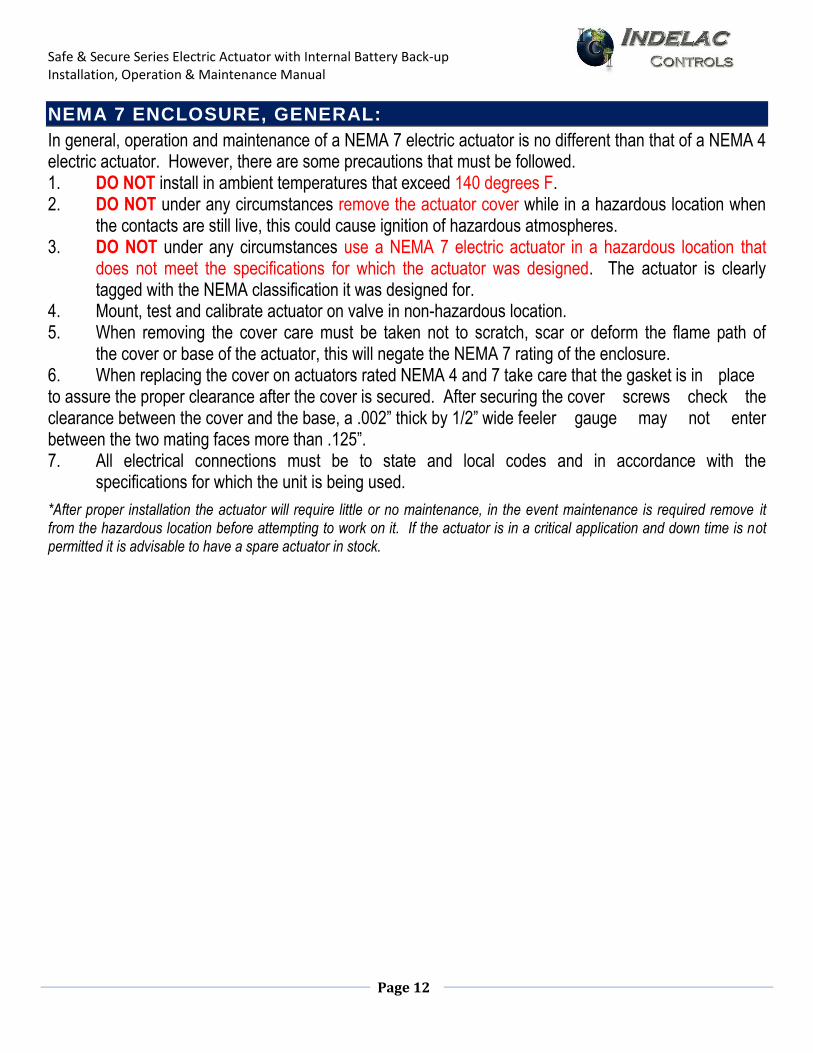
NEMA 7 ENCLOSURE, GENERAL:
In general, operation and maintenance of a NEMA 7 electric actuator is no different than that of a NEMA 4 electric actuator. However, there are some precautions that must be followed. 1. DO NOT install in ambient temperatures that exceed 140 degrees F. 2. DO NOT under any circumstances remove the actuator cover while in a hazardous location when
the contacts are still live, this could cause ignition of hazardous atmospheres. 3. DO NOT under any circumstances use a NEMA 7 electric actuator in a hazardous location that does not meet the specifications for which the actuator was designed. The actuator is clearly tagged with the NEMA classification it was designed for. 4. Mount, test and calibrate actuator on valve in non-hazardous location. 5. When removing the cover care must be taken not to scratch, scar or deform the flame path of the cover or base of the actuator, this will negate the NEMA 7 rating of the enclosure. 6. When replacing the cover on actuators rated NEMA 4 and 7 take care that the gasket is in place to assure the proper clearance after the cover is secured. After securing the cover screws check the clearance between the cover and the base, a .002” thick by 1/2” wide feeler gauge may not enter between the two mating faces more than .125”. 7. All electrical connections must be to state and local codes and in accordance with the specifications for which the unit is being used.
*After proper installation the actuator will require little or no maintenance, in the event maintenance is required remove it from the hazardous location before attempting to work on it. If the actuator is in a critical application and down time is not permitted it is advisable to have a spare actuator in stock.
Safe & Secure Series Electric Actuator with Internal Battery Back-up Installation, Operation & Maintenance Manual
Page 13
Safe & Secure Series Electric Actuator with Internal Battery Back-up Installation, Operation & Maintenance Manual
Page 14
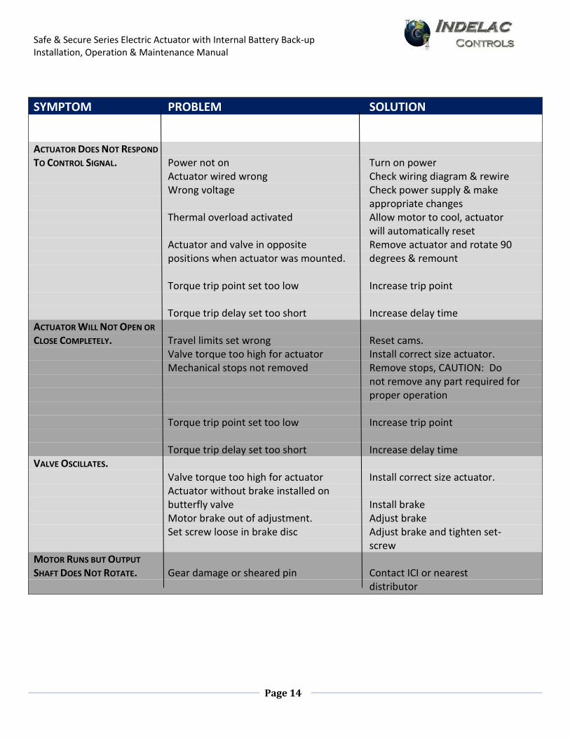
- >>> TROUBLE SHOOTING <<< -
SYMPTOM PROBLEM SOLUTION ACTUATOR DOES NOT RESPOND TO CONTROL SIGNAL. Power not on Turn on power Actuator wired wrong Check wiring diagram & rewire Wrong voltage Check power supply & make appropriate changes Thermal overload activated Allow motor to cool, actuator will automatically reset Actuator and valve in opposite Remove actuator and rotate 90 positions when actuator was mounted. degrees & remount Torque trip point set too low Increase trip point Torque trip delay set too short Increase delay time ACTUATOR WILL NOT OPEN OR CLOSE COMPLETELY. Travel limits set wrong Reset cams. Valve torque too high for actuator Install correct size actuator. Mechanical stops not removed Remove stops, CAUTION: Do not remove any part required for proper operation Torque trip point set too low Increase trip point Torque trip delay set too short Increase delay time VALVE OSCILLATES. Valve torque too high for actuator Install correct size actuator. Actuator without brake installed on butterfly valve Install brake Motor brake out of adjustment. Adjust brake Set screw loose in brake disc Adjust brake and tighten set- screw MOTOR RUNS BUT OUTPUT SHAFT DOES NOT ROTATE. Gear damage or sheared pin Contact ICI or nearest distributor
Safe & Secure Series Electric Actuator with Internal Battery Back-up Installation, Operation & Maintenance Manual
Page 15
NOTES
___________________________________________________________________
___________________________________________________________________
___________________________________________________________________
___________________________________________________________________
___________________________________________________________________
___________________________________________________________________
___________________________________________________________________
___________________________________________________________________
___________________________________________________________________
___________________________________________________________________
___________________________________________________________________
___________________________________________________________________
___________________________________________________________________
___________________________________________________________________
___________________________________________________________________
___________________________________________________________________
___________________________________________________________________
___________________________________________________________________
___________________________________________________________________
___________________________________________________________________
___________________________________________________________________
___________________________________________________________________
___________________________________________________________________
___________________________________________________________________
___________________________________________________________________
___________________________________________________________________
___________________________________________________________________
___________________________________________________________________
___________________________________________________________________
___________________________________________________________________

Safe & Secure Series Electric Actuator with Internal Battery Back-up Installation, Operation & Maintenance Manual
Page 16
Contact Information
Debbie Voges [email protected] 859-727-7890 ext. 100
Matt Robinson [email protected] 859-727-7890 ext. 109
Talbot Caywood [email protected] 859-727-7890 ext. 110
For News & Updates, Check Out Our Blog: www.blog.indelac.com