Embed Size (px)
Citation preview

PR
OD
UC
T I
NF
OR
MA
TIO
N
Safe Robotics Area ProtectionOPEN ACCESS FOR SAFE PRODUCTIVITY
Safety systems

S a f e R o b o t i c s A r e a P r o t e c t i o n | S I C K 8022384/2019-11-06Subject to change without notice
2
Safe Robotics Area Protection OVERVIEW
Documentation
Detailed documentation with SISTEMA file, wiring diagram, safety laser scanner configuration file and operating instructions
Hardware
Pre-selected and proven safety hardware components
Logic
Logic with safe and non-safe functions tested and confirmed by safety experts
SAFETY SYSTEMS FROM SICK: EVERYTHING FROM A SINGLE SOURCE
SAFE PRODUCTIVITY FOR ROBOTICS APPLICATIONSWith many years of experience in the field of industrial safety and the automation and safe-guarding of robot applications, SICK knows the challenges its customers face very well. To keep both safety and productivity at the highest possible level, SICK is offering safety systems, such as Safe Robotics Area Protection, which serve as the basis for quick and easy safeguarding of freely-accessible robot applications. The focus is on close and, at the same time, safe interaction between humans and robots. The result: High productivity as well as increased efficiency and improved ergonomics in robot applications.
Optimal protection for freely-accessible robot applications
Easy integration into the robot controller
Available as software for the Flexi Soft safety controller or as configuration logic for Flexi Classic
Safe Robotics Area Protection offers your workers safe access to hazardous robot areas. The special feature: The safety logic is ideally aligned to the robot system used, thereby ensuring optimal operation of your application. The integration of the safety systems is very simple, since all required components for user-friendly and time-saving commissioning come from SICK. In addition, you can easily adapt the safeguarded areas to the requirements of the respective production steps, thereby optimizing work processes.

S a f e R o b o t i c s A r e a P r o t e c t i o n | S I C K8022384/2019-11-06Subject to change without notice
3
Aim for high productivity
Prevent unnecessary machine downtime and benefit from the option of automatic restart.
Future-proof investment
Stay flexible! You can adapt Safe Robotics Area Protection to your individual requirements, extend it with modules and therefore be prepared for changing requirements and future challenges. All safety systems come from a single source: From SICK, the expert in the field of industrial safety.
Guarantee safety
Take advantage of unrestricted and safe access to the hazardous area of the robot at all times. Integration into the robot controller was tested and optimized by SICK.
Save time and money
Save time and money for integration into your robot controller with pre-selected safety hardware components, a safe, ready-made and tested functional logic as well as detailed documentation including a wiring diagram and operating instructions.
Safe Robotics Area Protection is available in different variants which vary based on their principle of operation.
sBot Stop
Unspecific variants • sBot Stop
- page 8
A selection guide for the right safety system can be found on - page 10
sBot Speed
Unspecific variants • sBot Speed
Manufacturer-specific variants • sBot Speed – UR (Universal Robots) • sBot Speed – YA (Yaskawa)
- page 4
Manufacturer-specific variants with presence detection
• sBot Speed CIP – FA (FANUC)- page 6

S a f e R o b o t i c s A r e a P r o t e c t i o n | S I C K 8022384/2019-11-06Subject to change without notice
4
System variants PRINCIPLE OF OPERATION
Flexible safety system: Optimally adapt the fields of the safety laser scanner to the application environment.
Easy to expand: Implement additional safety functions into the safety controller at any time.
sBot SpeedWITH SPEED REDUCTION FOR FEWER DOWNTIMESThe sBot Speed system variants ensure safety and flexibility because they intelligently combine the func-tions of a safety laser scanner with those of the Flexi Soft safety controller. The non-safe automation functions and the safe functions have been developed and tested, meaning that the sBot Speed is easy to integrate into the most common robot controllers. The safety systems adapt robot operation to the respective position of the worker. This increases productivity, as downtimes are reduced and workflows optimized.
A. As unspecific variants with S300 Mini Remote or microScan3 Core safety laser scanners for the most common robot controllers
sBot Speed is available in different variants:B. As variants optimally aligned
to the UR3, UR5 and UR10 Universal Robots models with the S300 Mini Remote safety laser scanner
C. As variants optimally aligned to the DX200, YRC1000 and YRC1000micro Yaskawa robot controllers with the microScan3 Core safety laser scanner
• Consideration of the two operating modes “Running mode” and “Programming mode” in order to enable the operating staff to program the robot
• Description of the additional safety components required to comply with safety standards, e.g. reset pushbutton and operating mode selector switch
• All necessary robot-specific parameter settings, wiring diagram and SISTEMA file are contained in the detailed documentation and ensure quick commissioning
• Consideration of the two operat-ing modes “Running mode” and “Programming mode” in order to enable the operating staff to pro-gram the robot
• All necessary robot-specific pa-rameter settings, wiring diagram and SISTEMA file are contained in the detailed documentation and ensure quick commissioning

S a f e R o b o t i c s A r e a P r o t e c t i o n | S I C K8022384/2019-11-06Subject to change without notice
5
PRINCIPLE OF OPERATION System variants
PRINCIPLE OF OPERATION BASED ON A CNC MACHINE
FIELD SET 1 FIELD SET 2
SPEED REDUCTION
FIELD SET 1
AUTOMATIC RESTART*
FIELD SET 2
With sBot Speed, the safety laser scanner uses two different field sets which consist of a warning field (yellow) and a protective field (red). The minimum distance of each protective field must be defined based on the robot speed.
If a worker enters the warning field, the safety controller initiates a reduction of the robot speed. When the safely reduced speed is reached, dynamic protective field adaptation takes place: The safety system switches from field set 1 to field set 2, whose protective field is smaller than that of field set 1.
! "
If the worker exits the hazardous area, the robot restarts automatically after additional sequence monitoring*, with reduced speed at first. As soon as the worker leaves the protective field and warning field, the robot accelerates back to full speed.
The robot stops when the worker enters the protective field. $§
* This function may only be used if permitted in line with the risk assessment and all requirements for the use of this safety system are fulfilled.

S a f e R o b o t i c s A r e a P r o t e c t i o n | S I C K 8022384/2019-11-06Subject to change without notice
6
System variants PRINCIPLE OF OPERATION
CIP Safety™
Integration of the safety system into the robot controller is safe and easy and is done directly via EtherNet/IP™ CIP Safety™. Flexi Soft works as the originator and triggers the safety functions in the robot controller.
sBot Speed CIP – FAMORE OPTIONS FOR CHALLENGING ROBOT APPLICATIONS sBot Speed CIP – FA combines the microScan3 Core – EFI-pro safety laser scanner with the Flexi Soft safety controller and the EFI-pro gateway. The system variant is optimally aligned to the FANUC R-30iB Plus robot controller based on EtherNet/IP™ CIP Safety™. In addition to the general advantages of the sBot Speed the sBot Speed CIP – FA offers other benefits oriented specifically to the use of FANUC robots. Thanks to safe simultaneous field monitoring, this safety system is also suitable for freely- accessible robot applications in which persons can walk behind the safeguarded area, for example in palletizer systems. The communication between the safety system and FANUC robot controller can be set easily thanks to the pre-configured parameters. In addition, the CIP Safety™ safety interface also minimizes wiring effort, since only one cable is enough to connect to the robot controller.
EtherNet/IP™ CIP Safety™: Profit from optimal robot integration and the option of setting additional functions.
Easy to extend: Integrate other SICK components into the safety system in the blink of an eye.

S a f e R o b o t i c s A r e a P r o t e c t i o n | S I C K8022384/2019-11-06Subject to change without notice
7
PRINCIPLE OF OPERATION System variants
PRINCIPLE OF OPERATION USING THE EXAMPLE OF A PALLETIZER SYSTEM
The sBot Speed CIP – FA works with various protective fields of the microScan3 Core – EFI-pro safety laser scanner which are simultaneously monitored. The minimum distance of each protective field is defined based on the robot speed.
If a worker enters protective field 1, the safety controller initiates a reduction of the robot speed.! "
As soon as the person leaves protective field 1, the robot automatically restarts after successful testing of the safe sequence monitoring*. Manual restart of the robot is only required if the person does not correctly follow the expected exit sequence or enters protective field 3.
The robot does not stop until the person enters the second defined protective field and therefore comes too close to the hazardous area. $§
* This function may only be used if permitted in line with the risk assessment and all requirements for the use of this safety system are fulfilled.
S a f e R o b o t i c s A r e a P r o t e c t i o n | S I C K 8022384/2019-11-06Subject to change without notice
8
System variants PRINCIPLE OF OPERATION
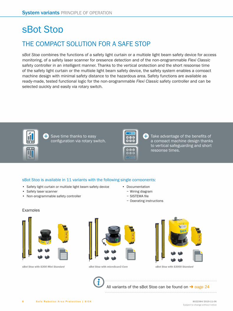
sBot Stop
Take advantage of the benefits of a compact machine design thanks to vertical safeguarding and short response times.
Save time thanks to easy configuration via rotary switch.
• Safety light curtain or multiple light beam safety device • Safety laser scanner • Non-programmable safety controller
• Documentation − Wiring diagram − SISTEMA file − Operating instructions
sBot Stop with S3000 StandardsBot Stop with microScan3 Core
THE COMPACT SOLUTION FOR A SAFE STOPsBot Stop combines the functions of a safety light curtain or a multiple light beam safety device for access monitoring, of a safety laser scanner for presence detection and of the non-programmable Flexi Classic safety controller in an intelligent manner. Thanks to the vertical protection and the short response time of the safety light curtain or the multiple light beam safety device, the safety system enables a compact machine design with minimal safety distance to the hazardous area. Safety functions are available as ready-made, tested functional logic for the non-programmable Flexi Classic safety controller and can be selected quickly and easily via rotary switch.
sBot Stop is available in 11 variants with the following single components:
Examples
sBot Stop with S300 Mini Standard
All variants of the sBot Stop can be found on - page 24

S a f e R o b o t i c s A r e a P r o t e c t i o n | S I C K8022384/2019-11-06Subject to change without notice
9
PRINCIPLE OF OPERATION System variants
PRINCIPLE OF OPERATION BASED ON A CNC MACHINE
Depending on the application, the safety system offers the option of per-forming a manual or automatic restart*. It can only reset after the worker has left the hazardous area.
The secondary protective device detects whether people are located in the protective field and ensures that the robot remains safely stopped as long as the worker is in the hazardous area.
sBot Stop is characterized by two protective devices: A safety light curtain or a multiple light beam safety device is used as the primary protective device for access control for the robot application, a safety laser scanner is used as the secondary protective device for presence detection.
! If the worker interrupts the light beams of the primary protective device, the robot stops."
$§
* This function may only be used if permitted in line with the risk assessment and all requirements for the use of this safety system are fulfilled.

S a f e R o b o t i c s A r e a P r o t e c t i o n | S I C K 8022384/2019-11-06Subject to change without notice
1 0
Selection guide and application fields
SELECTION GUIDE
System variants Robot type Robot stopping process
Robot restart Interface with the robot controller
Included opto-electronic
protective devices
Type of safety controller
Features of the safety system Parts for order Page
Unsp
ecifi
c
Univ
ersa
l Rob
ots
Yask
awa
FAN
UC
With
pre
viou
s sp
eed
redu
ctio
n
Imm
edia
te s
top
Auto
mat
ic
Man
ual
Dis
cret
e I/
Os
Ethe
rnet
/IP™
CIP
Saf
ety™
Safe
ty la
ser s
cann
er
Safe
ty li
ght c
urta
in o
r mul
tiple
lig
ht b
eam
saf
ety
devi
ce
Prog
ram
mab
le F
lexi
Sof
t saf
ety
cont
rolle
r
Non
-pro
gram
mab
le F
lexi
Cla
ssic
sa
fety
con
trolle
r
Flex
ibili
ty
Pres
ence
det
ectio
n
Low
spa
ce re
quire
men
t
Har
dwar
e
Soft
war
e pa
ckag
e
Har
dwar
e an
d lo
gic
Har
dwar
e an
d so
ftw
are
sBot Speed - 13
sBot Speed – UR - 13
sBot Speed – YA - 13
sBot Speed CIP – FA 1) - 19
sBot Stop 2) 2) - 24
1) With the third protective field.2) According to variant.
Auswahlhilfe
FIELDS OF APPLICATION
The area of application of the Safe Robotics Area Protection safety systems is constantly growing as robot applications are now nearly indispensable as supplements and support for work processes in most branches of industry.
Automotive and parts suppliers
E.g. in the production of electric engines

S a f e R o b o t i c s A r e a P r o t e c t i o n | S I C K8022384/2019-11-06Subject to change without notice
1 1
Selection guide and application fields
SELECTION GUIDE
System variants Robot type Robot stopping process
Robot restart Interface with the robot controller
Included opto-electronic
protective devices
Type of safety controller
Features of the safety system Parts for order Page
Unsp
ecifi
c
Univ
ersa
l Rob
ots
Yask
awa
FAN
UC
With
pre
viou
s sp
eed
redu
ctio
n
Imm
edia
te s
top
Auto
mat
ic
Man
ual
Dis
cret
e I/
Os
Ethe
rnet
/IP™
CIP
Saf
ety™
Safe
ty la
ser s
cann
er
Safe
ty li
ght c
urta
in o
r mul
tiple
lig
ht b
eam
saf
ety
devi
ce
Prog
ram
mab
le F
lexi
Sof
t saf
ety
cont
rolle
r
Non
-pro
gram
mab
le F
lexi
Cla
ssic
sa
fety
con
trolle
r
Flex
ibili
ty
Pres
ence
det
ectio
n
Low
spa
ce re
quire
men
t
Har
dwar
e
Soft
war
e pa
ckag
e
Har
dwar
e an
d lo
gic
Har
dwar
e an
d so
ftw
are
sBot Speed - 13
sBot Speed – UR - 13
sBot Speed – YA - 13
sBot Speed CIP – FA 1) - 19
sBot Stop 2) 2) - 24
1) With the third protective field.2) According to variant.
Auswahlhilfe
Electronics and solar
E.g. in quality control work stations
Consumer goods
E.g. in packaging stations

S a f e R o b o t i c s A r e a P r o t e c t i o n | S I C K 8022384/2019-11-06Subject to change without notice
1 2
Safe Robotics Area Protection SAFETY SYSTEMS
Product descriptionThe Safe Robotics Area Protection safety systems from SICK are a starting point for safe human-robot interaction and enable cooperative and freely-ac-cessible robot applications. The systems feature a tested functional logic which can be combined with safety sensors from SICK. Safe Robotics Area Protec-tion is also available as manufactur-er-specific variants, e.g. for Universal
Robots, FANUC and Yaskawa. Thanks to the detailed documentation and ro-bot-specific settings, these variants can be easily integrated into robot controls. The safety systems comply with interna-tional safety standards and enable an increase in productivity thanks to less downtime and optimized work process-es.
At a glance• Safety systems consist of hardware
and functional logic• Safety functions thanks to tested
functional logic• Generic or manufacturer-specific
variants for Universal Robots, FANUC and Yaskawa
• Documentation also includes wiring diagram, SISTEMA file and operating instructions
• Automatic robot restart possible• PL d
Your benefits• Free, safe access to cooperative
robot applications for high productivi-ty, less downtime, and optimum work processes
• High flexibility as the system is easy to adapt to the robot application and production environment
• Future-proof, as it can be flexibly adapted
• Detailed documentation for robot integration, compliant with relevant standards
• Low costs as the system is easy to integrate into industrial robot control-lers, thanks to generic or manufac-turer-specific variants for Universal Robots, FANUC and Yaskawa
• Reliable safety for your plant – prov-en functional logic, developed by SICK experts
Safe Robotics Area ProtectionSAFETY SYSTEMS
Safe Robotics Area Protection
Subject to change without notice
.
OPEN ACCESS FOR SAFE PRODUCTIVITY
Additional information
sBot Speed, sBot Speed – UR, sBot Speed – YADetailed technical data . . . . . . . . . . 13
Ordering information . . . . . . . . . . . . 18
Dimensional drawings . . . . . . . . . . . 14
Accessories . . . . . . . . . . . . . . . . . . . . .16
sBot Speed CIP – FADetailed technical data . . . . . . . . . . 19
Ordering information . . . . . . . . . . . . 19
Dimensional drawings . . . . . . . . . . . 20
Accessories . . . . . . . . . . . . . . . . . . . . .21
sBot StopDetailed technical data . . . . . . . . . . .24
Ordering information . . . . . . . . . . . . .25
Dimensional drawings . . . . . . . . . . . .25
Accessories . . . . . . . . . . . . . . . . . . . . .31
- www.sick.com/Safe_Robotics_Area_ProtectionFor more information, simply enter the link or scan the QR code and get direct access to technical data, CAD design models, operating instructions, software, application examples, and much more.
ABCDEF
HIJKLMNOPQRST

S a f e R o b o t i c s A r e a P r o t e c t i o n | S I C K8022384/2019-11-06Subject to change without notice
1 3
SAFETY SYSTEMS Safe Robotics Area Protection
sBot Speed, sBot Speed – UR, sBot Speed – YADetailed technical data
sBot Speed sBot Speed – UR sBot Speed – YA
Robot controller Generic Universal Robots: CB 3.0 oder CB 3.1
Yaskawa: DX200, YRC1000, YRC1000micro
Safety task Hazardous area protection
Stopping process of the robot With speed reduction
Robot restart Automatic
Performance level PL d (ISO 13849-1)
Supply voltage VS 24 V DC (16.8 V DC ... 28.8 V DC)
Ambient operating temperature –10 °C ... +50 °C
Storage temperature –20 °C ... +50 °C
Air humidity 90% at 50 °C (EN 61131-2)
Safe state in the event of a fault The safety-related semiconductor outputs are in the OFF state.
Safety laser scanner microScan3 Core I/O / S300 Mini Remote (depending on type)
S300 Mini Remote microScan3 Core I/O
Protective field range 5.5 m / 3 m (depending on type)
3 m 5.5 m
Safety controller included Flexi Soft
Safety controller type Programmable
Interface Discrete I/Os
Functions
sBot Speed sBot Speed – UR sBot Speed – YA
Emergency stop
Shut down in the event of an emergency situation
l
Prevent unexpected restarting after an emergency stop
l
Initiate a safety stop
Automated reset l
Safety-rated monitored speed
Trigger safety-rated monitored speed l
Switch field sets l
Operating mode
Operating mode selection – l –
Enabling device - manual operating mode – l –
Operating mode selection (implemented in robot control)
– l
Enabling device - manual operating mode (implemented in robot control)
– l
ABCDEF
HIJKLMNOPQRST

S a f e R o b o t i c s A r e a P r o t e c t i o n | S I C K 8022384/2019-11-06Subject to change without notice
1 4
Safe Robotics Area Protection SAFETY SYSTEMS
Ordering information
Variant Robot controller Safety controller included Safety laser scanner included
Protec-tive field
range
Product type
Type Part no.
sBot Speed Generic
Flexi Soft:1 x system plug MPL01 x main module CPU12 x I/O module XTIO2 x relay module UE410-4RO4
microScan3 Core I/O 5.5 m Hardware,
Software SAPPB2D-08X0039 1093376
S300 Mini Remote 3 m Hardware,
Software SAPPB2D-08X0040 1093377
sBot Speed –
UR
Universal Robots: CB 3.0
or CB 3.1
Flexi Soft:1 x system plug MPL01 x main module CPU13 x I/O module XTIO
S300 Mini Remote 3 m Hardware,
Software SAPPB2D-08X0041 1096129
sBot Speed – YA
Yaskawa: DX200,
YRC1000, YRC1000micro
– – – Software SAPPB2D-08X0055 1614202
Flexi Soft:1 x system plug MPL01 x main module CPU12 x I/O module XTIO2 x relay module UE410-4RO4
microScan3 Core I/O 5.5 m Hardware SAPPB2D-08X0055 1106014
Please note: Hardware and software have to be ordered for the sBot Speed – YA.
Dimensional drawings (Dimensions in mm (inch))
microScan3 Core I/O
12
3
112(4.41)
Ø 99.5(Ø 3.92)
≤ 200(≤ 7.87)
M5×7.5(M5×0.3)
85(3.35)
44(1.73)12
(0.47)
135.
1(5
.32)
111.
1(4
.37)
250
(9.8
4)
47.1
(1.8
5)47
.9(1
.89)
40.1
(1.5
8)
≥ 25
(≥ 0
.98)
≥ 25
(≥ 0
.98)
22 (0.8
7)36
.1(1
.42)
36.9
(1.4
5)
1 Mirror axis of rotation2 Scan plane3 Required viewing slit
ABCDEF
HIJKLMNOPQRST

S a f e R o b o t i c s A r e a P r o t e c t i o n | S I C K8022384/2019-11-06Subject to change without notice
1 5
SAFETY SYSTEMS Safe Robotics Area Protection
S300 Mini Remote
Ø 94 (3.70)11
6 (4
.57)
79.7
(3.1
4)
43.3
(1.7
0)
36.5 (1.44)
73 (2.87)
102 (4.02)
Max. 200 (7.87)
104 (4.09)
54.5 (2.15)
Min
. 15
(0.5
9)M
in. 1
5 (0
.59) 36
.4(1
.43)
23.8
(0.9
4)
M5 x 7.5
5(0.50)
10.5(0.41)49±0.2 (1.93)
250 (9.84)
43.3
(1.7
0)
ABCDEF
HIJKLMNOPQRST
S a f e R o b o t i c s A r e a P r o t e c t i o n | S I C K 8022384/2019-11-06Subject to change without notice
1 6
Safe Robotics Area Protection SAFETY SYSTEMS
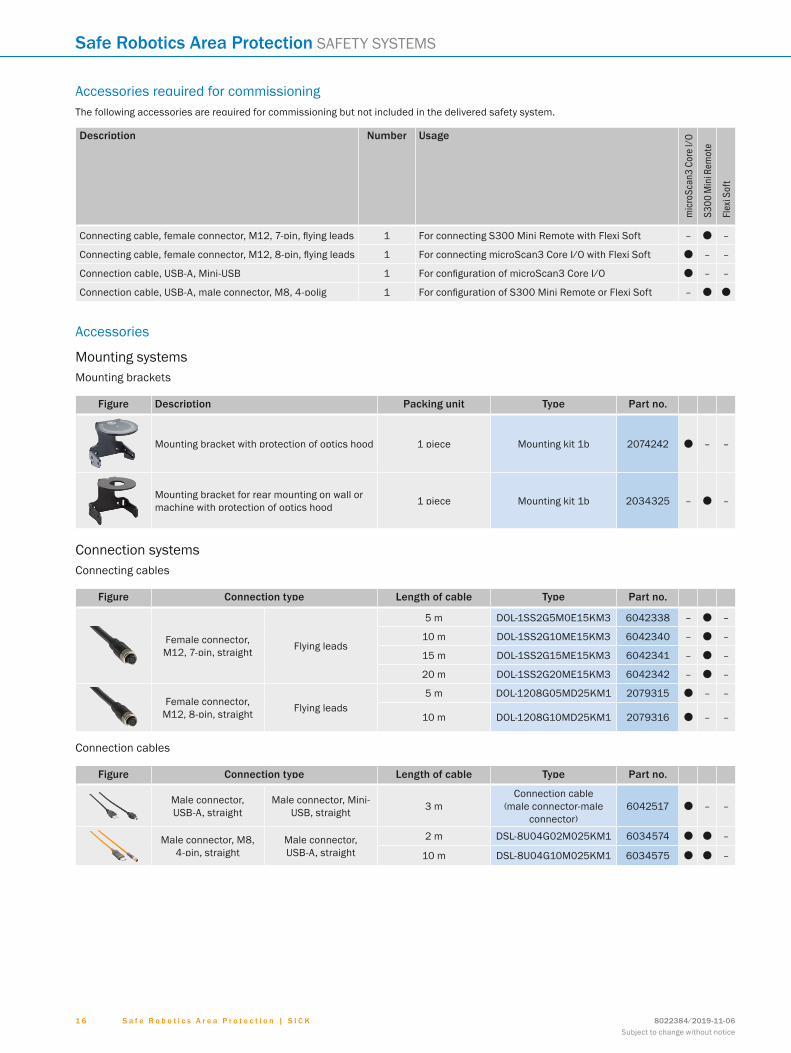
Accessories required for commissioningThe following accessories are required for commissioning but not included in the delivered safety system.
Description Number Usage
mic
roSc
an3
Core
I/O
S300
Min
i Rem
ote
Flex
i Sof
t
Connecting cable, female connector, M12, 7-pin, flying leads 1 For connecting S300 Mini Remote with Flexi Soft – O –
Connecting cable, female connector, M12, 8-pin, flying leads 1 For connecting microScan3 Core I/O with Flexi Soft O – –
Connection cable, USB-A, Mini-USB 1 For configuration of microScan3 Core I/O O – –
Connection cable, USB- A, male connector, M8, 4- polig 1 For configuration of S300 Mini Remote or Flexi Soft – O O
Accessories
Mounting systemsMounting brackets
Figure Description Packing unit Type Part no.
Mounting bracket with protection of optics hood 1 piece Mounting kit 1b 2074242 O – –
Mounting bracket for rear mounting on wall or machine with protection of optics hood 1 piece Mounting kit 1b 2034325 – O –
Connection systemsConnecting cables
Figure Connection type Length of cable Type Part no.
Female connector, M12, 7-pin, straight Flying leads
5 m DOL-1SS2G5M0E15KM3 6042338 – O –
10 m DOL-1SS2G10ME15KM3 6042340 – O –
15 m DOL-1SS2G15ME15KM3 6042341 – O –
20 m DOL-1SS2G20ME15KM3 6042342 – O –
Female connector, M12, 8-pin, straight Flying leads
5 m DOL-1208G05MD25KM1 2079315 O – –
10 m DOL-1208G10MD25KM1 2079316 O – –
Connection cables
Figure Connection type Length of cable Type Part no.
Male connector, USB-A, straight
Male connector, Mini-USB, straight 3 m
Connection cable (male connector-male
connector)6042517 O – –
Male connector, M8, 4-pin, straight
Male connector, USB-A, straight
2 m DSL-8U04G02M025KM1 6034574 O O –
10 m DSL-8U04G10M025KM1 6034575 O O –
ABCDEF
HIJKLMNOPQRST
S a f e R o b o t i c s A r e a P r o t e c t i o n | S I C K8022384/2019-11-06Subject to change without notice
1 7
SAFETY SYSTEMS Safe Robotics Area Protection
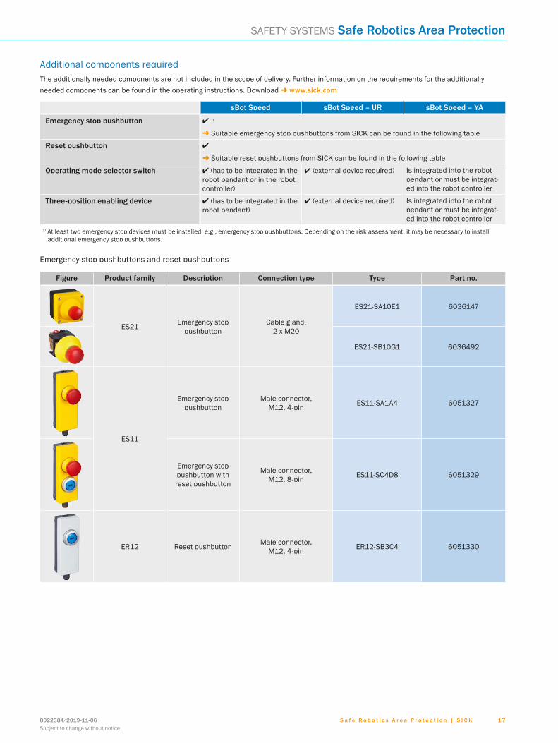
Additional components requiredThe additionally needed components are not included in the scope of delivery. Further information on the requirements for the additionally needed components can be found in the operating instructions. Download - www.sick.com
sBot Speed sBot Speed – UR sBot Speed – YA
Emergency stop pushbutton l 1)
- Suitable emergency stop pushbuttons from SICK can be found in the following table
Reset pushbutton l
- Suitable reset pushbuttons from SICK can be found in the following table
Operating mode selector switch l (has to be integrated in the robot pendant or in the robot controller)
l (external device required) Is integrated into the robot pendant or must be integrat-ed into the robot controller
Three-position enabling device l (has to be integrated in the robot pendant)
l (external device required) Is integrated into the robot pendant or must be integrat-ed into the robot controller
1) At least two emergency stop devices must be installed, e.g., emergency stop pushbuttons. Depending on the risk assessment, it may be necessary to install additional emergency stop pushbuttons.
Emergency stop pushbuttons and reset pushbuttons
Figure Product family Description Connection type Type Part no.
ES21 Emergency stop pushbutton
Cable gland, 2 x M20
ES21-SA10E1 6036147
ES21-SB10G1 6036492
ES11
Emergency stop pushbutton
Male connector, M12, 4-pin ES11-SA1A4 6051327
Emergency stop pushbutton with reset pushbutton
Male connector, M12, 8-pin ES11-SC4D8 6051329
ER12 Reset pushbutton Male connector, M12, 4-pin ER12-SB3C4 6051330
ABCDEF
HIJKLMNOPQRST

S a f e R o b o t i c s A r e a P r o t e c t i o n | S I C K 8022384/2019-11-06Subject to change without notice
1 8
Safe Robotics Area Protection SAFETY SYSTEMS
Accessories for emergency stop pushbuttons and reset pushbuttons
Figure Connection type Conductor cross-section
Length of cable
Type Part no.
ES11
-SA1
A4
ES11
-SC4
D8
ER12
-SB3
C4
Female connector, M12, 4-pin, straight Flying leads 0,34 mm²
10 m YF2A14-100VB3XLEAX 2096236 O – O
15 m YF2A14-150VB3XLEAX 2096237 O – O
Female connector, M12, 8-pin, straight Flying leads 0,25 mm²
10 m YF2A18-100UA5XLEAX 2095654 – O –
15 m YF2A18-150UA5XLEAX 2095679 – O –
ABCDEF
HIJKLMNOPQRST

S a f e R o b o t i c s A r e a P r o t e c t i o n | S I C K8022384/2019-11-06Subject to change without notice
1 9
SAFETY SYSTEMS Safe Robotics Area Protection
sBot Speed CIP – FADetailed technical data
Robot controller FANUC: R-30iB Plus
Safety task Hazardous area protection
Stopping process of the robot With speed reduction
Robot restart Automatic
Performance level PL d (ISO 13849-1)
Supply voltage VS 24 V DC (16.8 V DC ... 30 V DC)
Ambient operating temperature –10 °C ... +50 °C
Storage temperature –25 °C ... +70 °C
Air humidity 90% at 50 °C (EN 61131-2)
Safe state in the event of a fault The safety outputs via the network are logic 0.
Safety laser scanner microScan3 Core – EFI-pro
Protective field range 5.5 m
Safety controller included Flexi Soft
Safety controller type Programmable
Interface EtherNet/IP™ CIP Safety™
Functions
Emergency stop
Shut down in the event of an emergency situation
l
Prevent unexpected restarting after an emer-gency stop
l
Initiate a safety stop
Automated reset and restart with safe se-quence monitoring
l
Optional manual reset l
Safety-rated monitored speed
Trigger safety-rated monitored speed l
Operating mode
Operating mode selection (implemented in robot control)
l
Enabling device - manual operating mode (implemented in robot control)
l
Ordering information
Variant Robot type Safety controller included Safety laser scanner included
Protec-tive field
range
Product type
Type Part no.
sBotSpeed CIP
– FA
FANUC: R-30iB Plus
Flexi Soft:1 x system plug MPL01 x main module CPU01 x I/O module XTIO1 x Gateway-Modul FX3-GEPR0
microScan3 Core – EFI-pro 5.5 m Hardware Hardware Kit 1105347
– – – – – Software SAPPC2D-08XS002 1614143
Please note: Hardware and software have to be ordered for the sBot Speed CIP.
ABCDEF
HIJKLMNOPQRST

S a f e R o b o t i c s A r e a P r o t e c t i o n | S I C K 8022384/2019-11-06Subject to change without notice
2 0
Safe Robotics Area Protection SAFETY SYSTEMS
Dimensional drawings (Dimensions in mm (inch))
microScan3 Core – EFI-pro
12
3
112(4.41)
Ø 99.5(Ø 3.92)
≤ 200(7.87)
M5×7.5(M5×0.3)
85(3.35)
44(1.73)12
(0.47)
150.
8(5
.94)
111.
1(4
.37)
47.1
(1.8
5)63
.6(2
.5)
40.1
(1.5
8)
≥ 25
(≥ 0
.98)
≥ 25
(≥ 0
.98)
22 (0.8
7)36
.1(1
.42)
52.6
(2.0
7)
173.
7(6
.84)
132
(5.2
)
1 Mirror axis of rotation2 Scan plane3 Required viewing slit
ABCDEF
HIJKLMNOPQRST

S a f e R o b o t i c s A r e a P r o t e c t i o n | S I C K8022384/2019-11-06Subject to change without notice
2 1
SAFETY SYSTEMS Safe Robotics Area Protection
Accessories required for commissioningThe following accessories are required for commissioning but not included in the delivered safety system.
Description Number Usage
Connecting cable, female connector, M12, 4-pin, flying leads 1 To supply voltage to the microScan3 Core – EFI-pro
Connection cable, USB-A, Mini-USB 1 For configuration of microScan3 Core – EFI-pro
Connection cable, male connector, M12, 4-pin, mail connec-tor, RJ-45, 8-pin 1 – 2 1) For connecting microScan3 Core – EFI-pro with Flexi Soft Gateway
or/and robot controller1) Dependent on the network structure
Accessories
Mounting systemsMounting brackets
Figure Description Packing unit Type Part no.
Mounting bracket with protection of optics hood 1 piece Mounting kit 1b 2074242
Connection systemsConnecting cables
• Model: PUR, halogen-free, unshielded
Figure Connection type Conductor cross-section
Length of cable Type Part no.
Female connector, M12, 4-pin, angled Flying leads 0,75 mm²
5 m DOL-1204W05MC75KM0 2079294
10 m DOL-1204W10MC75KM0 2079295
20 m DOL-1204W20MC75KM0 2089704
Female connector, M12, 4-pin, straight Flying leads 0,75 mm²
5 m DOL-1204G05MC75KM0 2079291
10 m DOL-1204G10MC75KM0 2079292
20 m DOL-1204G20MC75KM0 2089703
Connection cables
Figure Connection type Model Length of cable Type Part no.
Male connector, M12, 4-pin, straight
Male connector, RJ45, 8-pin,
straight
PUR, halogen-free, shielded
2 m SSL-2J04-G02ME60 6047916
5 m SSL-2J04-G05ME60 6047917
10 m SSL-2J04-G10ME60 6047918
20 m SSL-2J04-G20ME60 6063700
Male connector, M12, 4-pin, angled
Male connector, RJ45, 8-pin,
straight
PUR, halogen-free, shielded
2 m SSL-2J04-H02ME 6047911
5 m SSL-2J04-H05ME 6045287
10 m SSL-2J04-H10ME 6045288
20 m SSL-2J04-H20ME 6063701
Male connector, USB-A, straight
Male connector, Mini-USB, straight Shielded 3 m
Connection cable (male connector-male connec-
tor)6042517
ABCDEF
HIJKLMNOPQRST
S a f e R o b o t i c s A r e a P r o t e c t i o n | S I C K 8022384/2019-11-06Subject to change without notice
2 2
Safe Robotics Area Protection SAFETY SYSTEMS
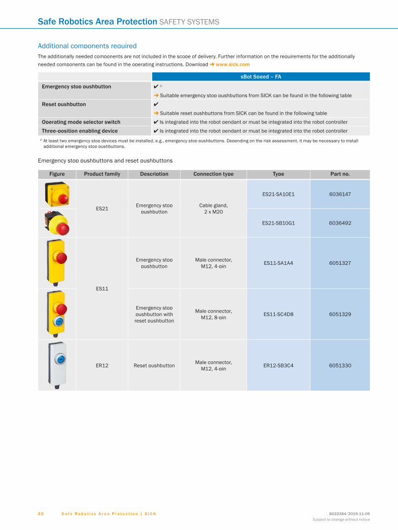
Additional components requiredThe additionally needed components are not included in the scope of delivery. Further information on the requirements for the additionally needed components can be found in the operating instructions. Download - www.sick.com
sBot Speed – FA
Emergency stop pushbutton l 1)
- Suitable emergency stop pushbuttons from SICK can be found in the following table
Reset pushbutton l
- Suitable reset pushbuttons from SICK can be found in the following table
Operating mode selector switch l Is integrated into the robot pendant or must be integrated into the robot controller
Three-position enabling device l Is integrated into the robot pendant or must be integrated into the robot controller1) At least two emergency stop devices must be installed, e.g., emergency stop pushbuttons. Depending on the risk assessment, it may be necessary to install
additional emergency stop pushbuttons.
Emergency stop pushbuttons and reset pushbuttons
Figure Product family Description Connection type Type Part no.
ES21 Emergency stop pushbutton
Cable gland, 2 x M20
ES21-SA10E1 6036147
ES21-SB10G1 6036492
ES11
Emergency stop pushbutton
Male connector, M12, 4-pin ES11-SA1A4 6051327
Emergency stop pushbutton with reset pushbutton
Male connector, M12, 8-pin ES11-SC4D8 6051329
ER12 Reset pushbutton Male connector, M12, 4-pin ER12-SB3C4 6051330
ABCDEF
HIJKLMNOPQRST

S a f e R o b o t i c s A r e a P r o t e c t i o n | S I C K8022384/2019-11-06Subject to change without notice
2 3
SAFETY SYSTEMS Safe Robotics Area Protection
Accessories for emergency stop pushbuttons and reset pushbuttons
Figure Connection type Conductor cross-section
Length of cable
Type Part no.
ES11
-SA1
A4
ES11
-SC4
D8
ER12
-SB3
C4
Female connector, M12, 4-pin, straight Flying leads 0,34 mm²
10 m YF2A14-100VB3XLEAX 2096236 O – O
15 m YF2A14-150VB3XLEAX 2096237 O – O
Female connector, M12, 8-pin, straight Flying leads 0,25 mm²
10 m YF2A18-100UA5XLEAX 2095654 – O –
15 m YF2A18-150UA5XLEAX 2095679 – O –
ABCDEF
HIJKLMNOPQRST

S a f e R o b o t i c s A r e a P r o t e c t i o n | S I C K 8022384/2019-11-06Subject to change without notice
2 4
Safe Robotics Area Protection SAFETY SYSTEMS
sBot StopDetailed technical data
Robot controller Generic
Safety task Hazardous area protection
Stopping process of the robot Stop only
Robot restart Manual / automatic (depending on type)
Performance level PL d (ISO 13849-1)
Supply voltage VS 24 V DC (16.8 V DC ... 28.8 V DC)
Ambient operating temperature –10 °C ... +50 °C
Storage temperature –20 °C ... +50 °C
Air humidity 90% at 50 °C (EN 61131-2)
Safe state in the event of a fault The safety-related semiconductor outputs are in the OFF state.
Safety sensors
Primary protective device (access control) Safety light curtain / Multiple light beam safety devices (depending on type)
Secondary protective device (presence detection)
Safety laser scanner
Safety light curtain deTec4 Core
Protective field height 1,500 mm / 1,200 mm (depending on type)
Resolution 30 mm
Scanning range 15 m
Multiple light beam safety devices deTem4 Core
Number of beams 4
Beam separation 300 mm
Scanning range 17 m
Safety laser scanner S300 Mini Standard / microScan3 Core / S3000 Standard (depending on type)
Protective field range 3 m / 5.5 m (depending on type)
Safety controller included Flexi Classic
Safety controller type Non programmable
Interface Discrete I/Os
Functions
Emergency stop
Shut down in the event of an emergency situation
l
Prevent unexpected restarting after an emergency stop
l
Initiate a safety stop
Automated reset l (depending on type)
Manual reset l (depending on type)
ABCDEF
HIJKLMNOPQRST

S a f e R o b o t i c s A r e a P r o t e c t i o n | S I C K8022384/2019-11-06Subject to change without notice
2 5
SAFETY SYSTEMS Safe Robotics Area Protection
Ordering information
Robot restart
Safety controller included
Primary protective device (access detection)
Secondary protective de-vice (presence detection)
Type Part no.
AutomaticFlexi Classic:1 x main module MU4T01 x input module 8DI
Safety light curtaindeTec4 CoreProtective field height: 1,500 mmResolution: 30 mm
Safety laser scannermicroScan3 Core I/OProtective field range: 5.5 m
SAPPB2D-08X0049 1097909
Safety laser scannerS300 Mini StandardProtective field range: 3 m
SAPPB2D-08X0047 1097907
Multiple light beam safety devicesdeTem4 CoreNumber of beams: 4Beam separation: 300 mm
Safety laser scannermicroScan3 Core I/OProtective field range: 5.5 m
SAPPB2D-08X0050 1097911
Safety laser scannerS300 Mini StandardProtective field range: 3 m
SAPPB2D-08X0048 1097908
Manual Flexi Classic:1 x main module MU4T0
Safety light curtaindeTec4 CoreProtective field height: 1,200 mmResolution: 30 mm
Safety laser scannermicroScan3 Core I/OProtective field range: 5.5 m
SAPPB2D-08X0051 1098639
Safety laser scannerS3000 StandardProtective field range: 5.5 m
SAPPB2D-08X0053 1098641
Safety light curtaindeTec4 CoreProtective field height: 1,500 mmResolution: 30 mm
Safety laser scannermicroScan3 Core I/OProtective field range: 5.5 m
SAPPB2D-08X0045 1097905
Safety laser scannerS300 Mini StandardProtective field range: 3 m
SAPPB2D-08X0043 1097902
Safety laser scannerS3000 StandardProtective field range: 5.5 m
SAPPB2D-08X0052 1098640
Multiple light beam safety devicesdeTem4 CoreNumber of beams: 4Beam separation
Safety laser scannermicroScan3 Core I/OProtective field range: 5.5 m
SAPPB2D-08X0046 1097906
Safety laser scannerS300 Mini StandardProtective field range: 3 m
SAPPB2D-08X0044 1097904
Please note: Each part number includes hardware and logic.
ABCDEF
HIJKLMNOPQRST

S a f e R o b o t i c s A r e a P r o t e c t i o n | S I C K 8022384/2019-11-06Subject to change without notice
2 6
Safe Robotics Area Protection SAFETY SYSTEMS
Dimensional drawings (Dimensions in mm (inch))
deTec4 Core
34(1.34)
30 (1.1
8)
30.7
(1.2
1)
� �
� � �
5(0
.2)
4(0
.16)
14 (0.5
5)
56.8
(2.2
4)56
.8(2
.24)
56.8
(2.2
4)
L L
29.5(1.16)
30.7(1.21)
7(0.28)
12(0.47)
6.3
(0.2
5)
L=150 (5.91)
13 (0.5
1)13
.8(0
.54)
21.1
(0.8
3)21
.8(0
.86) 10
6.8
(4.2
)
Protective field height L
1,200 (47.24) 1,213 (47.76)
1,500 (59.06) 1,512 (59.53)
ABCDEF
HIJKLMNOPQRST

S a f e R o b o t i c s A r e a P r o t e c t i o n | S I C K8022384/2019-11-06Subject to change without notice
2 7
SAFETY SYSTEMS Safe Robotics Area Protection
deTem4 Core
115.
2(4
.54)
30.7
(1.2
1)
34(1.33)
L = 150(L = 5.91)
56.2
(2.2
1)
86 (3.3
9)
56.8
(2.2
4)56
.8(2
.24)
S1
L
29.5(1.16)
6.3
(0.2
5)
30.7(1.21)
Number of beams S (Beam separation) L (Length)
4 300 (11.81) 1,072 (42.20)
ABCDEF
HIJKLMNOPQRST

S a f e R o b o t i c s A r e a P r o t e c t i o n | S I C K 8022384/2019-11-06Subject to change without notice
2 8
Safe Robotics Area Protection SAFETY SYSTEMS
microScan3 Core I/O
12
3
112(4.41)
Ø 99.5(Ø 3.92)
≤ 200(≤ 7.87)
M5×7.5(M5×0.3)
85(3.35)
44(1.73)12
(0.47)
135.
1(5
.32)
111.
1(4
.37)
250
(9.8
4)
47.1
(1.8
5)47
.9(1
.89)
40.1
(1.5
8)
≥ 25
(≥ 0
.98)
≥ 25
(≥ 0
.98)
22 (0.8
7)36
.1(1
.42)
36.9
(1.4
5)
1 Mirror axis of rotation2 Scan plane3 Required viewing slit
ABCDEF
HIJKLMNOPQRST

S a f e R o b o t i c s A r e a P r o t e c t i o n | S I C K8022384/2019-11-06Subject to change without notice
2 9
SAFETY SYSTEMS Safe Robotics Area Protection
S300 Mini Standard
Ø 94 (3.70)11
6 (4
.57)
79.7
(3.1
4)
43.3
(1.7
0)
36.5 (1.44)
73 (2.87)
102 (4.02)
Max. 200 (7.87)
104 (4.09)
54.5 (2.15)
Min
. 15
(0.5
9)M
in. 1
5 (0
.59) 36
.4(1
.43)
23.8
(0.9
4)
M5 x 7.5
5(0.50)
10.5(0.41)49±0.2 (1.93)
250 (9.84)
43.3
(1.7
0)
ABCDEF
HIJKLMNOPQRST

S a f e R o b o t i c s A r e a P r o t e c t i o n | S I C K 8022384/2019-11-06Subject to change without notice
3 0
Safe Robotics Area Protection SAFETY SYSTEMS
S3000 Standard
Area to be keptclear duringinstallation ofthe scanner
Axis of rotation of motor
Conn
ecto
r ran
ge:
appr
ox. 2
70 (1
0.63
)
Refe
renc
epo
ints
for
mou
ntin
g
Beam
dia
met
erSe
nder
= 1
5 (0
.59)Be
am d
iam
eter
Rece
iver
= 4
4 (1
.73)
147 (5.79)136.8 (5.39)
M6
x 8
120
(4.7
2)31
.7(1
.25)
55 (2
.17)
35 (1.3
8)
M8 x 9 M13.523
(0.91)
78.5
(3.0
9)53
.2(2
.09)
185
(7.2
8)
211
(8.3
1)
27.8(1.09) 65.2 (2.57)
93 (3.66)
160 (6.30)
63 (2
.48)
77.5 (3.05)
155 (6.10)
92.5 (3.64)
155 (6.10)
211
(8.3
1)18
5 (7
.28)
31.7
(1.25)
63 (2
.48)
ABCDEF
HIJKLMNOPQRST

S a f e R o b o t i c s A r e a P r o t e c t i o n | S I C K8022384/2019-11-06Subject to change without notice
3 1
SAFETY SYSTEMS Safe Robotics Area Protection
Accessories required for commissioningThe following accessories are required for commissioning but not included in the delivered safety system.
Description Number Usage
deTe
c4 C
ore
deTe
m4
Core
mic
roSc
an3
Core
I/O
S300
Min
i Sta
ndar
d
S300
0 St
anda
rd
Connecting cable, female connector, M12, 5-pin, flying leads 2 For connecting deTec4 Core or deTem4 Core with Flexi Classic O O – – –
Connecting cable, female connector, M12, 8-pin, flying leads 1 For connecting microScan3 Core I/O or S300 Mini Standard with Flexi Classic – – O O –
System plug S3000 Standard with connecting cable, flying leads 1 For connecting S3000 Standard with Flexi Classic – – – – O
Connection cable, USB-A, Mini-USB 1 For configuration of microScan3 Core I/O – – O – –
Connection cable, USB-A, male connector, M8, 4- polig 1 For configuration of S300 Mini Standard or S3000 Standard – – – O O
Accessories
Mounting systems
Mounting brackets
Figure Description Packing unit Type Part no.
Mounting bracket with protection of optics hood 1 piece Mounting kit 1b 2074242 – – O –
Mounting bracket for rear mounting on wall or machine with protection of optics hood 1 piece Mounting kit 1b 2034325 – – – O –
Mounting bracket for direct mounting, from the rear, on wall or machine, not adjustable 1 piece Mounting kit 1 2015623 – – – O
Mounting bracket for rear mounting on wall or machine, adjustable longitudinal and lateral axes, only in conjunction with Mounting kit 1 (2015623)
1 piece Mounting kit 2 2015624 – – – – O
ABCDEF
HIJKLMNOPQRST

S a f e R o b o t i c s A r e a P r o t e c t i o n | S I C K 8022384/2019-11-06Subject to change without notice
3 2
Safe Robotics Area Protection SAFETY SYSTEMS
Connection systems
Connecting cables
Figure Connection type Conductor cross-
section
Model Length of cable
Type Part no.
deTe
c4 C
ore
deTe
m4
Core
mic
roSc
an3
Core
I/O
S300
Min
i Sta
ndar
d
S300
0 St
anda
rd
Female connector, M12, 5-pin,
straight
Flying leads 0.34 mm²PUR, hal-ogen-free, unshielded
2 m YF2A15-020UB5XLEAX 2095617 O O – – –
5 m YF2A15-050UB5XLEAX 2095618 O O – – –
10 m YF2A15-100UB5XLEAX 2095619 O O – – –
Female connector, M12, 8-pin,
straight
Flying leads 0.25 mm²
PUR, hal-ogen-free, unshielded
5 m DOL-1208G05MD25KM1 2079315 – – O – –
10 m DOL-1208G10MD25KM1 2079316 – – O – –
PUR, hal-ogen-free, shielded
5 m DOL-127SG05ME25KM0 2076541 – – – O –
10 m DOL-127SG10ME25KM0 2076543 – – – O –
15 m DOL-127SG15ME25KM0 2076544 – – – O –
System plug with connecting cable
• Model: Pre-assembled, not for use of incremental encoders, integrated configuration storage, PVC, unshielded• Items supplied: With 1 x cable gland M20, 1 x blanking plug M20, 2 x blanking plug M12
Figure Connection type
Number of cores
Length of cable
Specialty Type Part no.
Flying leads 9-wire
5 m Cable connection at the rear SX0A-B0905G 2049222 – – – – O
10 mCable connection
at the top
SX0A-B0910B 2027171 – – – – O
20 m SX0A-B0920B 2027814 – – – – O
Connection cables
Figure Connection type Length of cable Type Part no.
USB-A Mini-USB 3 mConnection cable (male connector-male connec-
tor)6042517 – – O – –
USB-A Male connector, M8, 4-pin, straight
2 m DSL-8U04G02M025KM1 6034574 – – – O O
10 m DSL-8U04G10M025KM1 6034575 – – – O O
ABCDEF
HIJKLMNOPQRST

S a f e R o b o t i c s A r e a P r o t e c t i o n | S I C K8022384/2019-11-06Subject to change without notice
3 3
SAFETY SYSTEMS Safe Robotics Area Protection
Additional components requiredThe additionally needed components are not included in the scope of delivery. Further information on the requirements for the additionally needed components can be found in the operating instructions. Download - www.sick.com
Relay module l
Emergency stop pushbutton l 1)
Reset pushbutton l
1) At least two emergency stop devices must be installed, e.g., emergency stop pushbuttons. Depending on the risk assessment, it may be necessary to install additional emergency stop pushbuttons.
- Suitable devices from SICK can be found in the following tables
Flexi Classic relay modules
Figure Suitable for Number of enable current contacts
Number of signalling current contacts
Number of contactor monitoring contacts
Type Part no.
Manual robot restart 2 1 1 UE410-2RO4 6032677
Automatic robot restart 4 2 2 UE410-4RO4 6032676
Emergency stop pushbuttons and reset pushbuttons
Figure Product family Description Connection type Type Part no.
ES21 Emergency stop pushbut-ton
Cable gland, 2 x M20
ES21-SA10E1 6036147
ES21-SB10G1 6036492
ES11
Emergency stop pushbut-ton
Male connector, M12, 4-pin ES11-SA1A4 6051327
Emergency stop pushbut-ton with reset pushbutton
Male connector, M12, 8-pin ES11-SC4D8 6051329
ER12 Reset pushbutton Male connector, M12, 4-pin ER12-SB3C4 6051330
ABCDEF
HIJKLMNOPQRST

S a f e R o b o t i c s A r e a P r o t e c t i o n | S I C K 8022384/2019-11-06Subject to change without notice
3 4
Safe Robotics Area Protection SAFETY SYSTEMS
Accessories for emergency stop pushbuttons and reset pushbuttons
Figure Connection type Conductor cross-section
Length of cable
Type Part no.
ES11
-SA1
A4
ES11
-SC4
D8
ER12
-SB3
C4
Female connector, M12, 4-pin,
straightFlying leads 0,34 mm²
10 m YF2A14-100VB3XLEAX 2096236 O – O
15 m YF2A14-150VB3XLEAX 2096237 O – O
Female connector, M12, 8-pin,
straightFlying leads 0,25 mm²
10 m YF2A18-100UA5XLEAX 2095654 – O –
15 m YF2A18-150UA5XLEAX 2095679 – O –
ABCDEF
HIJKLMNOPQRST

SERVICES FOR MACHINES AND PLANTS: SICK LifeTime ServicesOur comprehensive and versatile LifeTime Services are the perfect addition to the comprehensive range of products from SICK. The services range from product-independent consulting to traditional product services.
Training and educationPractical, focused, and professional
Upgrade and retrofitsEasy, safe, and economical
Consulting and designSafe and professional
Verification and optimizationSafe and regularly inspected
Product and system supportReliable, fast, and on-site
SERVICES
REGISTER AT WWW.SICK.COM TO TAKE ADVANTAGE OF OUR FOLLOWING SERVICES FOR YOU
Access information on net prices and individual discounts.
Easily order online and track your delivery.
Check your history of all your orders and quotes.
Create, save, and share as many wish lists as you want.
Use the direct order to quickly order a big amount of products.
Check the status of your orders and quotes and get information on status changes by e-mail.
Save time by using past orders.
Easily export orders and quotes, suited to your systems.
m
m
m
m
m
m
m
m
S a f e R o b o t i c s A r e a P r o t e c t i o n | S I C K8022384/2019-11-06Subject to change without notice
3 5

SICK AG | Waldkirch | Germany | www.sick.com
SICK AT A GLANCESICK is a leading manufacturer of intelligent sensors and sensor solutions for industrial applications. With more than 9,700 employees and over 50 subsidiaries and equity investments as well as numerous agencies worldwide, SICK is always close to its customers. A unique range of products and services creates the perfect basis for controlling processes securely and efficiently, protecting individuals from accidents, and preventing damage to the environment.
SICK has extensive experience in various industries and understands their processes and requirements. With intelligent sensors, SICK delivers exactly what the customers need. In application centers in Europe, Asia, and North America, system solutions are tested and optimized in accordance with customer specifica-tions. All this makes SICK a reliable supplier and development partner.
Comprehensive services round out the offering: SICK LifeTime Services provide support throughout the machine life cycle and ensure safety and productivity.
That is “Sensor Intelligence.”
Worldwide presence:
Australia, Austria, Belgium, Brazil, Canada, Chile, China, Czech Republic, Denmark, Finland, France, Germany, Great Britain, Hungary, Hong Kong, India, Israel, Italy, Japan, Malaysia, Mexico, Netherlands, New Zealand, Norway, Poland, Romania, Russia, Singapore, Slovakia, Slovenia, South Africa, South Korea, Spain, Sweden, Switzerland, Taiwan, Thailand, Turkey, United Arab Emirates, USA, Vietnam.
Detailed addresses and further locations - www.sick.com
8022
384/
2019
-11-
06 ∙
SKO
M ∙
Pre
USm
od e
n49