Embed Size (px)
Citation preview
siemens.com/sivacon-S8
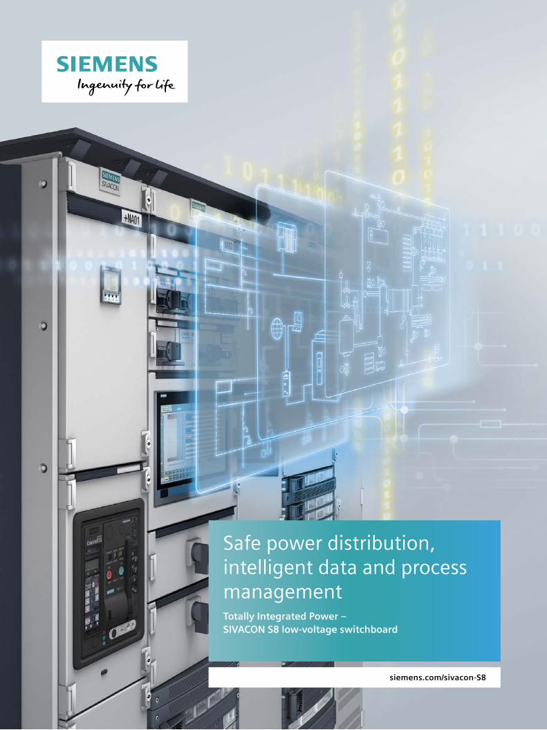
Safe power distribution, intelligent data and process managementTotally Integrated Power – SIVACON S8 low-voltage switchboard
2
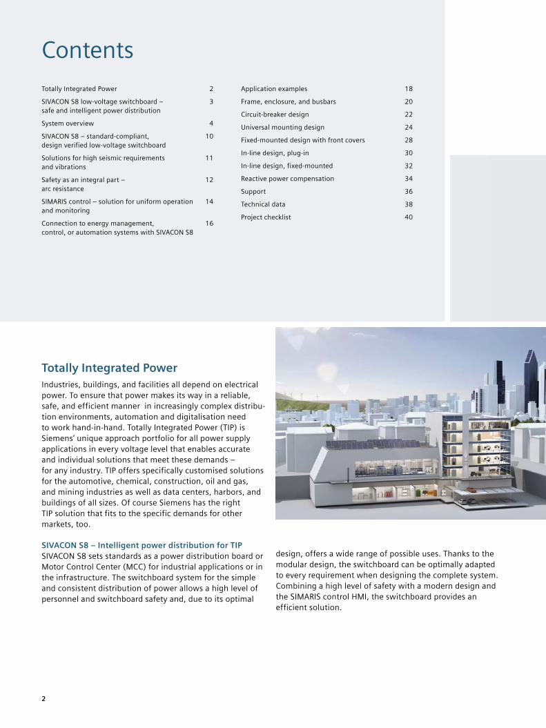
Totally Integrated PowerIndustries, buildings, and facilities all depend on electrical power. To ensure that power makes its way in a reliable, safe, and efficient manner in increasingly complex distribu-tion environments, automation and digitalisation need to work hand-in-hand. Totally Integrated Power (TIP) is Siemens’ unique approach portfolio for all power supply applications in every voltage level that enables accurate and individual solutions that meet these demands – for any industry. TIP offers specifically customised solutions for the automotive, chemical, construction, oil and gas, and mining industries as well as data centers, harbors, and buildings of all sizes. Of course Siemens has the right TIP solution that fits to the specific demands for other markets, too.
SIVACON S8 – Intelligent power distribution for TIPSIVACON S8 sets standards as a power distribution board or Motor Control Center (MCC) for industrial applications or in the infrastructure. The switchboard system for the simple and consistent distribution of power allows a high level of personnel and switchboard safety and, due to its optimal
design, offers a wide range of possible uses. Thanks to the modular design, the switchboard can be optimally adapted to every requirement when designing the complete system. Combining a high level of safety with a modern design and the SIMARIS control HMI, the switchboard provides an efficient solution.
Totally Integrated Power 2
SIVACON S8 low-voltage switchboard – safe and intelligent power distribution
3
System overview 4
SIVACON S8 – standard-compliant, design verified low-voltage switchboard
10
Solutions for high seismic requirements and vibrations
11
Safety as an integral part – arc resistance
12
SIMARIS control – solution for uniform operation and monitoring
14
Connection to energy management, control, or automation systems with SIVACON S8
16
Application examples 18
Frame, enclosure, and busbars 20
Circuit-breaker design 22
Universal mounting design 24
Fixed-mounted design with front covers 28
In-line design, plug-in 30
In-line design, fixed-mounted 32
Reactive power compensation 34
Support 36
Technical data 38
Project checklist 40
Contents
3
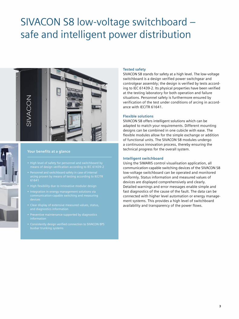
SIVACON S8 low-voltage switchboard – safe and intelligent power distribution
Tested safetySIVACON S8 stands for safety at a high level. The low-voltage switchboard is a design verified power switchgear and controlgear assembly; the design is verified by tests accord-ing to IEC 61439-2. Its physical properties have been verified at the testing laboratory for both operation and failure situations. Personnel safety is furthermore ensured by verification of the test under conditions of arcing in accord-ance with IEC/TR 61641.
Flexible solutionsSIVACON S8 offers intelligent solutions which can be adapted to match your requirements. Different mounting designs can be combined in one cubicle with ease. The flexible modules allow for the simple exchange or addition of functional units. The SIVACON S8 modules undergo a continuous innovation process, thereby ensuring the technical progress for the overall system.
Intelligent switchboardUsing the SIMARIS control visualisation application, all communication-capable switching devices of the SIVACON S8 low-voltage switchboard can be operated and monitored uniformly. Status information and measured values of devices are displayed comprehensively and clearly. Detailed warnings and error messages enable simple and fast diagnostics of the cause of the fault. The data can be connected with higher level automation or energy manage-ment systems. This provides a high level of switchboard availability and transparency of the power flows.
Your benefits at a glance
• High level of safety for personnel and switchboard by means of design verification according to IEC 61439-2
• Personnel and switchboard safety in case of internal arcing proven by means of testing according to IEC/TR 61641
• High flexibility due to innovative modular design
• Integration in energy management solutions via communication-capable switching and measuring devices
• Clear display of extensive measured values, status, and diagnostics information
• Preventive maintenance supported by diagnostics information
• Consistently design verified connection to SIVACON 8PS busbar trunking systems
4
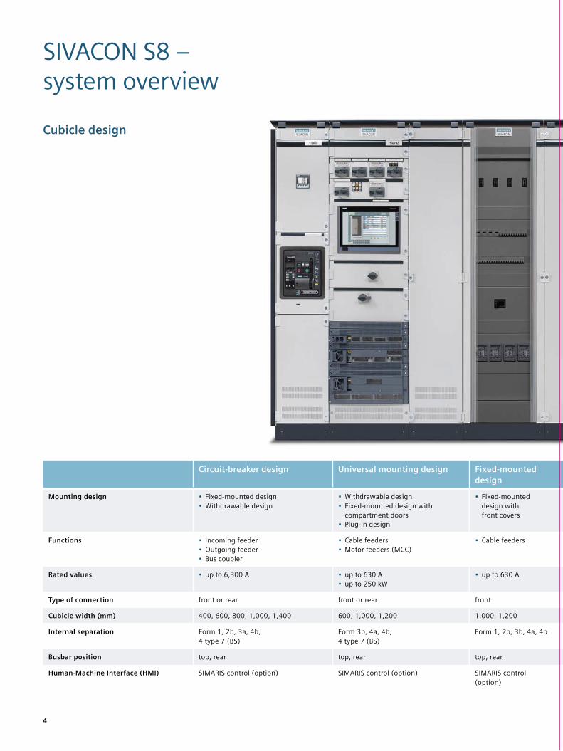
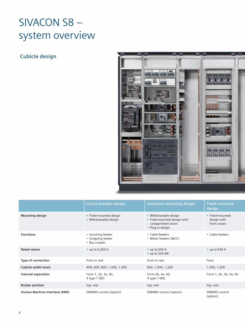
SIVACON S8 – system overview
Cubicle design
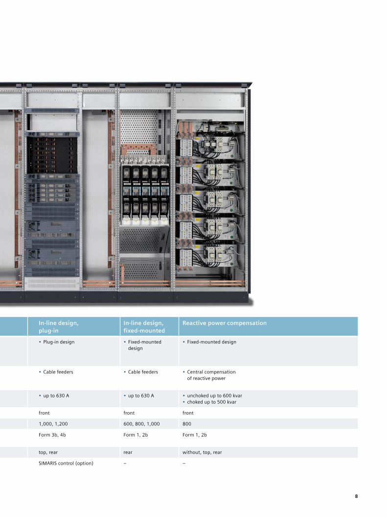
Circuit-breaker design Universal mounting design Fixed-mounted design
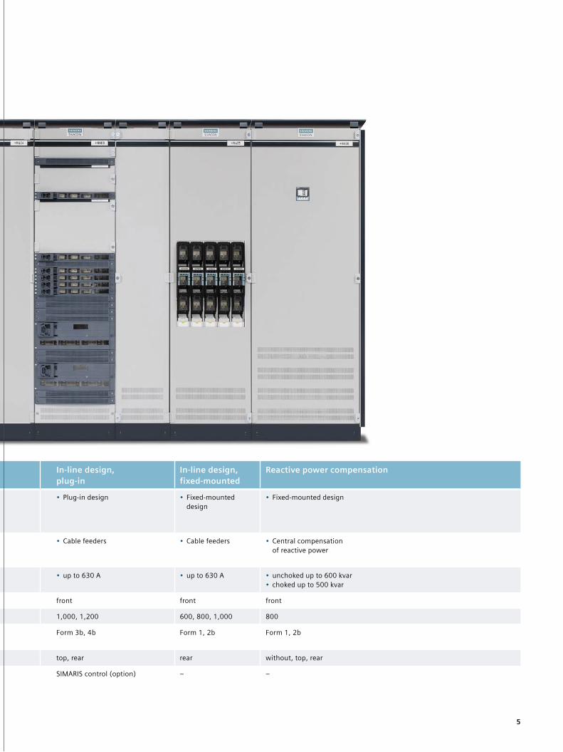
In-line design, plug-in
In-line design, fixed-mounted
Reactive power compensation
Mounting design • Fixed-mounted design• Withdrawable design
• Withdrawable design• Fixed-mounted design with
compartment doors• Plug-in design
• Fixed-mounted design with front covers
• Plug-in design • Fixed-mounted design
• Fixed-mounted design
Functions • Incoming feeder• Outgoing feeder• Bus coupler
• Cable feeders• Motor feeders (MCC)
• Cable feeders • Cable feeders • Cable feeders • Central compensation of reactive power
Rated values • up to 6,300 A • up to 630 A • up to 250 kW
• up to 630 A • up to 630 A • up to 630 A • unchoked up to 600 kvar• choked up to 500 kvar
Type of connection front or rear front or rear front front front front
Cubicle width (mm) 400, 600, 800, 1,000, 1,400 600, 1,000, 1,200 1,000, 1,200 1,000, 1,200 600, 800, 1,000 800
Internal separation Form 1, 2b, 3a, 4b, 4 type 7 (BS)
Form 3b, 4a, 4b, 4 type 7 (BS)
Form 1, 2b, 3b, 4a, 4b Form 3b, 4b Form 1, 2b Form 1, 2b
Busbar position top, rear top, rear top, rear top, rear rear without, top, rear
Human-Machine Interface (HMI) SIMARIS control (option) SIMARIS control (option) SIMARIS control (option)
SIMARIS control (option) – –
5
Circuit-breaker design Universal mounting design Fixed-mounted design
In-line design, plug-in
In-line design, fixed-mounted
Reactive power compensation
Mounting design • Fixed-mounted design• Withdrawable design
• Withdrawable design• Fixed-mounted design with
compartment doors• Plug-in design
• Fixed-mounted design with front covers
• Plug-in design • Fixed-mounted design
• Fixed-mounted design
Functions • Incoming feeder• Outgoing feeder• Bus coupler
• Cable feeders• Motor feeders (MCC)
• Cable feeders • Cable feeders • Cable feeders • Central compensation of reactive power
Rated values • up to 6,300 A • up to 630 A • up to 250 kW
• up to 630 A • up to 630 A • up to 630 A • unchoked up to 600 kvar• choked up to 500 kvar
Type of connection front or rear front or rear front front front front
Cubicle width (mm) 400, 600, 800, 1,000, 1,400 600, 1,000, 1,200 1,000, 1,200 1,000, 1,200 600, 800, 1,000 800
Internal separation Form 1, 2b, 3a, 4b, 4 type 7 (BS)
Form 3b, 4a, 4b, 4 type 7 (BS)
Form 1, 2b, 3b, 4a, 4b Form 3b, 4b Form 1, 2b Form 1, 2b
Busbar position top, rear top, rear top, rear top, rear rear without, top, rear
Human-Machine Interface (HMI) SIMARIS control (option) SIMARIS control (option) SIMARIS control (option)
SIMARIS control (option) – –
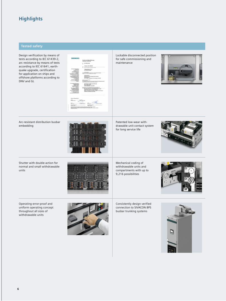
Highlights
Tested safety
Design verification by means of tests according to IEC 61439-2, arc resistance by means of tests according to IEC 61641, earth-quake upgrade, certification for application on ships and offshore platforms according to DNV and GL
Lockable disconnected position for safe commissioning and maintenance
Arc-resistant distribution busbar embedding
Patented low-wear with- drawable unit contact system for long service life
Shutter with double-action for normal and small withdrawable units
Mechanical coding of withdrawable units and compartments with up to 9,216 possibilities
Operating-error-proof and uniform operating concept throughout all sizes of withdrawable units
Consistently design verified connection to SIVACON 8PS busbar trunking systems
6
7
Circuit-breaker design Universal mounting design Fixed-mounted design
In-line design, plug-in
In-line design, fixed-mounted
Reactive power compensation
Mounting design • Fixed-mounted design• Withdrawable design
• Withdrawable design• Fixed-mounted design with
compartment doors• Plug-in design
• Fixed-mounted design with front covers
• Plug-in design • Fixed-mounted design
• Fixed-mounted design
Functions • Incoming feeder• Outgoing feeder• Bus coupler
• Cable feeders• Motor feeders (MCC)
• Cable feeders • Cable feeders • Cable feeders • Central compensation of reactive power
Rated values • up to 6,300 A • up to 630 A • up to 250 kW
• up to 630 A • up to 630 A • up to 630 A • unchoked up to 600 kvar• choked up to 500 kvar
Type of connection front or rear front or rear front front front front
Cubicle width (mm) 400, 600, 800, 1,000, 1,400 600, 1,000, 1,200 1,000, 1,200 1,000, 1,200 600, 800, 1,000 800
Internal separation Form 1, 2b, 3a, 4b, 4 type 7 (BS)
Form 3b, 4a, 4b, 4 type 7 (BS)
Form 1, 2b, 3b, 4a, 4b Form 3b, 4b Form 1, 2b Form 1, 2b
Busbar position top, rear top, rear top, rear top, rear rear without, top, rear
Human-Machine Interface (HMI) SIMARIS control (option) SIMARIS control (option) SIMARIS control (option)
SIMARIS control (option) – –
Cubicle design
SIVACON S8 – system overview
8
Circuit-breaker design Universal mounting design Fixed-mounted design
In-line design, plug-in
In-line design, fixed-mounted
Reactive power compensation
Mounting design • Fixed-mounted design• Withdrawable design
• Withdrawable design• Fixed-mounted design with
compartment doors• Plug-in design
• Fixed-mounted design with front covers
• Plug-in design • Fixed-mounted design
• Fixed-mounted design
Functions • Incoming feeder• Outgoing feeder• Bus coupler
• Cable feeders• Motor feeders (MCC)
• Cable feeders • Cable feeders • Cable feeders • Central compensation of reactive power
Rated values • up to 6,300 A • up to 630 A • up to 250 kW
• up to 630 A • up to 630 A • up to 630 A • unchoked up to 600 kvar• choked up to 500 kvar
Type of connection front or rear front or rear front front front front
Cubicle width (mm) 400, 600, 800, 1,000, 1,400 600, 1,000, 1,200 1,000, 1,200 1,000, 1,200 600, 800, 1,000 800
Internal separation Form 1, 2b, 3a, 4b, 4 type 7 (BS)
Form 3b, 4a, 4b, 4 type 7 (BS)
Form 1, 2b, 3b, 4a, 4b Form 3b, 4b Form 1, 2b Form 1, 2b
Busbar position top, rear top, rear top, rear top, rear rear without, top, rear
Human-Machine Interface (HMI) SIMARIS control (option) SIMARIS control (option) SIMARIS control (option)
SIMARIS control (option) – –
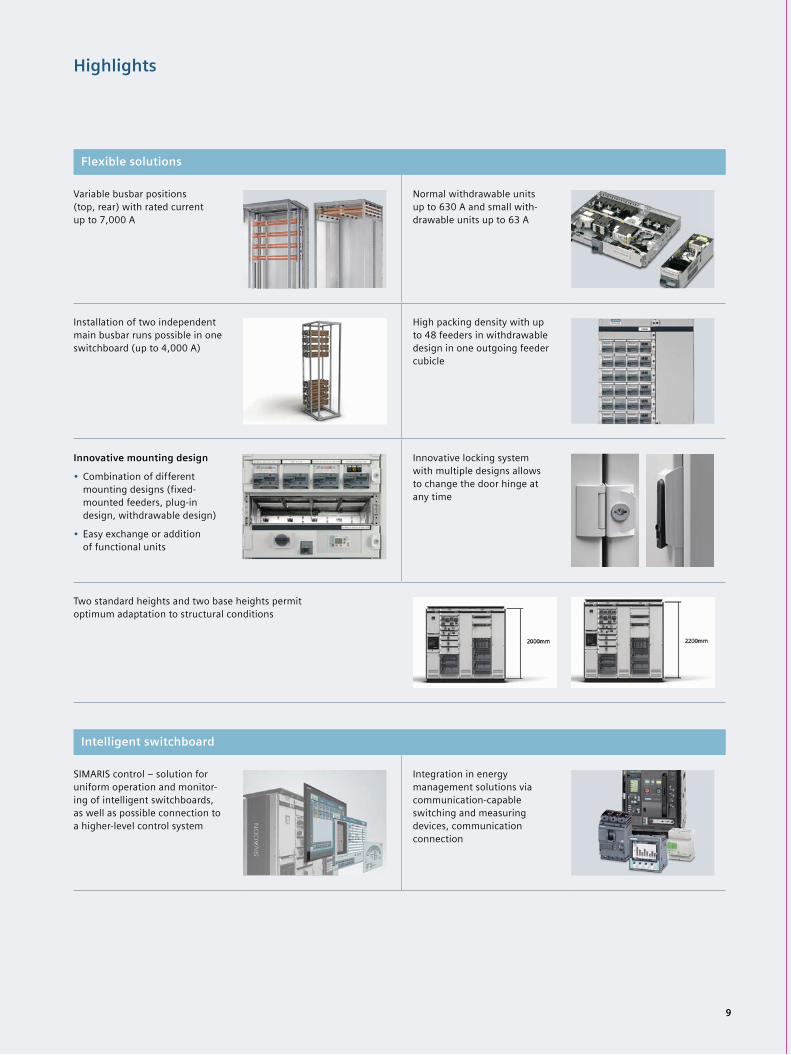
Highlights
Flexible solutions
Variable busbar positions (top, rear) with rated current up to 7,000 A
Normal withdrawable units up to 630 A and small with-drawable units up to 63 A
Installation of two independent main busbar runs possible in one switchboard (up to 4,000 A)
High packing density with up to 48 feeders in withdrawable design in one outgoing feeder cubicle
Innovative mounting design
• Combination of different mounting designs (fixed-mounted feeders, plug-in design, withdrawable design)
• Easy exchange or addition of functional units
Innovative locking system with multiple designs allows to change the door hinge at any time
Two standard heights and two base heights permit optimum adaptation to structural conditions
Intelligent switchboard
SIMARIS control – solution for uniform operation and monitor-ing of intelligent switchboards, as well as possible connection to a higher-level control system
Integration in energy management solutions via communication-capable switching and measuring devices, communication connection
9
10
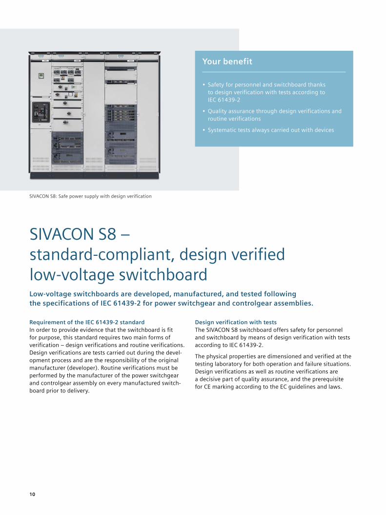
SIVACON S8 – standard-compliant, design verified low-voltage switchboardLow-voltage switchboards are developed, manufactured, and tested following the specifications of IEC 61439-2 for power switchgear and controlgear assemblies.
Requirement of the IEC 61439-2 standardIn order to provide evidence that the switchboard is fit for purpose, this standard requires two main forms of verification – design verifications and routine verifications. Design verifications are tests carried out during the devel-opment process and are the responsibility of the original manufacturer (developer). Routine verifications must be performed by the manufacturer of the power switchgear and controlgear assembly on every manufactured switch-board prior to delivery.
Design verification with testsThe SIVACON S8 switchboard offers safety for personnel and switchboard by means of design verification with tests according to IEC 61439-2.
The physical properties are dimensioned and verified at the testing laboratory for both operation and failure situations. Design verifications as well as routine verifications are a decisive part of quality assurance, and the prerequisite for CE marking according to the EC guidelines and laws.
Your benefit
• Safety for personnel and switchboard thanks to design verification with tests according to IEC 61439-2
• Quality assurance through design verifications and routine verifications
• Systematic tests always carried out with devices
SIVACON S8: Safe power supply with design verification
11
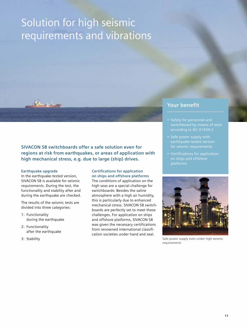
SIVACON S8 switchboards offer a safe solution even for regions at risk from earthquakes, or areas of application with high mechanical stress, e.g. due to large (ship) drives.
Earthquake upgradeIn the earthquake-tested version, SIVACON S8 is available for seismic requirements. During the test, the functionality and stability after and during the earthquake are checked.
The results of the seismic tests are divided into three categories:
1: Functionality during the earthquake
2: Functionality after the earthquake
3: Stability
Certifications for application on ships and offshore platformsThe conditions of application on the high seas are a special challenge for switchboards: Besides the saline atmosphere with a high air humidity, this is particularly due to enhanced mechanical stress. SIVACON S8 switch-boards are perfectly set to meet these challenges. For application on ships and offshore platforms, SIVACON S8 was given the necessary certifications from renowned international classifi-cation societies under hand and seal.
Your benefit
• Safety for personnel and switchboard by means of tests according to IEC 61439-2
• Safe power supply with earthquake-tested version for seismic requirements
• Certifications for application on ships and offshore platforms
Safe power supply even under high seismic requirements
Solution for high seismic requirements and vibrations
12
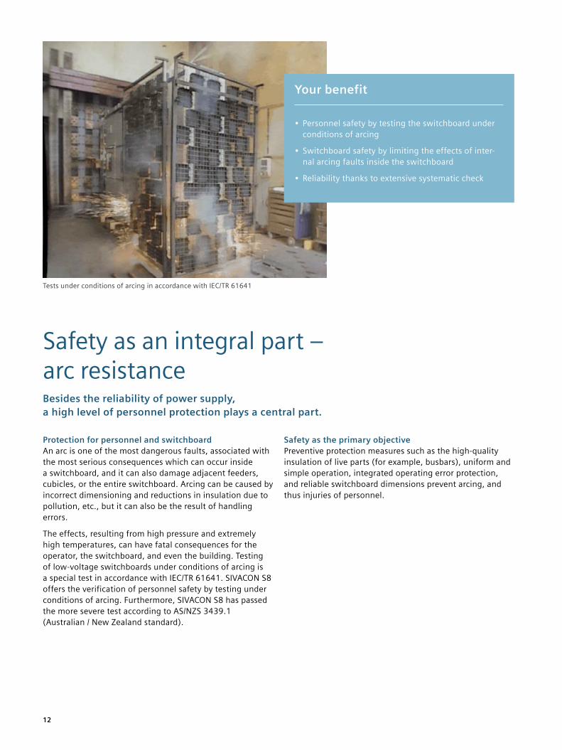
Safety as an integral part – arc resistanceBesides the reliability of power supply, a high level of personnel protection plays a central part.
Protection for personnel and switchboardAn arc is one of the most dangerous faults, associated with the most serious consequences which can occur inside a switchboard, and it can also damage adjacent feeders, cubicles, or the entire switchboard. Arcing can be caused by incorrect dimensioning and reductions in insulation due to pollution, etc., but it can also be the result of handling errors.
The effects, resulting from high pressure and extremely high temperatures, can have fatal consequences for the operator, the switchboard, and even the building. Testing of low-voltage switchboards under conditions of arcing is a special test in accordance with IEC/TR 61641. SIVACON S8 offers the verification of personnel safety by testing under conditions of arcing. Furthermore, SIVACON S8 has passed the more severe test according to AS/NZS 3439.1 (Australian / New Zealand standard).
Safety as the primary objectivePreventive protection measures such as the high-quality insulation of live parts (for example, busbars), uniform and simple operation, integrated operating error protection, and reliable switchboard dimensions prevent arcing, and thus injuries of personnel.
Tests under conditions of arcing in accordance with IEC/TR 61641
Your benefit
• Personnel safety by testing the switchboard under conditions of arcing
• Switchboard safety by limiting the effects of inter-nal arcing faults inside the switchboard
• Reliability thanks to extensive systematic check
13
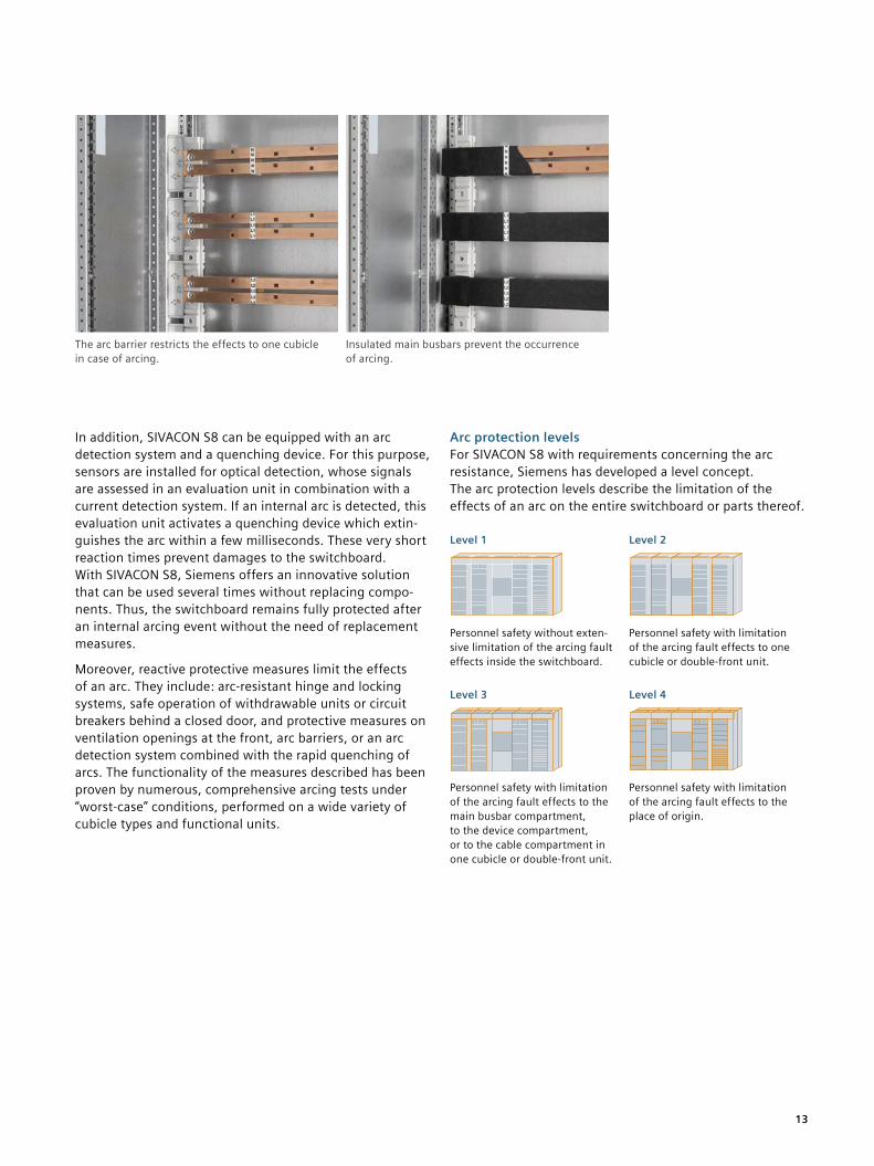
In addition, SIVACON S8 can be equipped with an arc detection system and a quenching device. For this purpose, sensors are installed for optical detection, whose signals are assessed in an evaluation unit in combination with a current detection system. If an internal arc is detected, this evaluation unit activates a quenching device which extin-guishes the arc within a few milliseconds. These very short reaction times prevent damages to the switchboard. With SIVACON S8, Siemens offers an innovative solution that can be used several times without replacing compo-nents. Thus, the switchboard remains fully protected after an internal arcing event without the need of replacement measures.
Moreover, reactive protective measures limit the effects of an arc. They include: arc-resistant hinge and locking systems, safe operation of withdrawable units or circuit breakers behind a closed door, and protective measures on ventilation openings at the front, arc barriers, or an arc detection system combined with the rapid quenching of arcs. The functionality of the measures described has been proven by numerous, comprehensive arcing tests under “worst-case” conditions, performed on a wide variety of cubicle types and functional units.
Arc protection levelsFor SIVACON S8 with requirements concerning the arc resistance, Siemens has developed a level concept. The arc protection levels describe the limitation of the effects of an arc on the entire switchboard or parts thereof.
Level 1 Level 2
Personnel safety without exten-sive limitation of the arcing fault effects inside the switchboard.
Personnel safety with limitation of the arcing fault effects to one cubicle or double-front unit.
Level 3 Level 4
Personnel safety with limitation of the arcing fault effects to the main busbar compartment, to the device compartment, or to the cable compartment in one cubicle or double-front unit.
Personnel safety with limitation of the arcing fault effects to the place of origin.
The arc barrier restricts the effects to one cubicle in case of arcing.
Insulated main busbars prevent the occurrence of arcing.
14
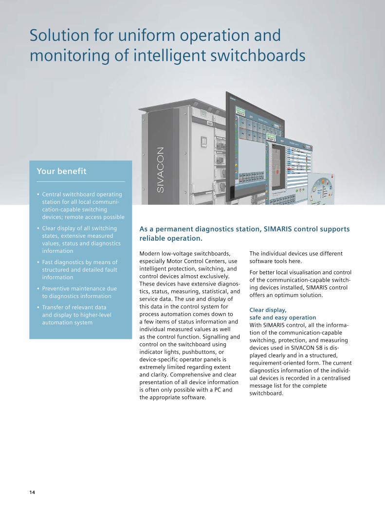
Solution for uniform operation and monitoring of intelligent switchboards
As a permanent diagnostics station, SIMARIS control supports reliable operation.
Modern low-voltage switchboards, especially Motor Control Centers, use intelligent protection, switching, and control devices almost exclusively. These devices have extensive diagnos-tics, status, measuring, statistical, and service data. The use and display of this data in the control system for process automation comes down to a few items of status information and individual measured values as well as the control function. Signalling and control on the switchboard using indicator lights, pushbuttons, or device-specific operator panels is extremely limited regarding extent and clarity. Comprehensive and clear presentation of all device information is often only possible with a PC and the appropriate software.
The individual devices use different software tools here.
For better local visualisation and control of the communication-capable switch-ing devices installed, SIMARIS control offers an optimum solution.
Clear display, safe and easy operationWith SIMARIS control, all the informa-tion of the communication-capable switching, protection, and measuring devices used in SIVACON S8 is dis-played clearly and in a structured, requirement-oriented form. The current diagnostics information of the individ-ual devices is recorded in a centralised message list for the complete switchboard.
Your benefit
• Central switchboard operating station for all local communi-cation-capable switching devices; remote access possible
• Clear display of all switching states, extensive measured values, status and diagnostics information
• Fast diagnostics by means of structured and detailed fault information
• Preventive maintenance due to diagnostics information
• Transfer of relevant data and display to higher-level automation system
15
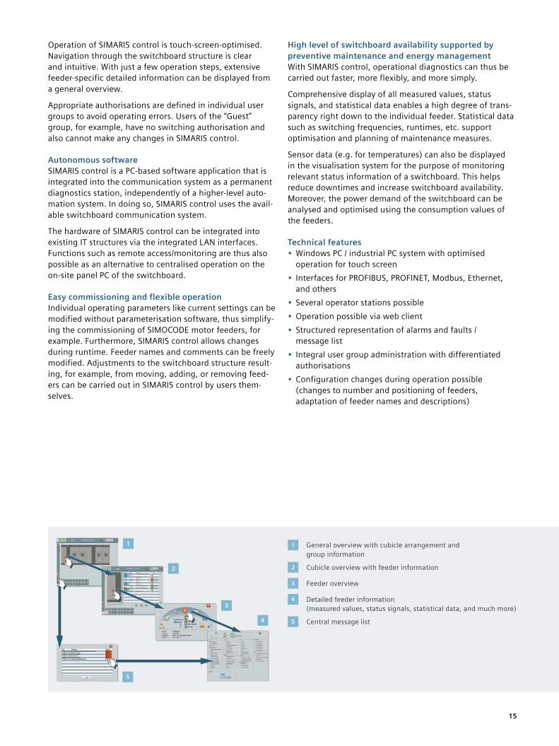
Operation of SIMARIS control is touch-screen-optimised. Navigation through the switchboard structure is clear and intuitive. With just a few operation steps, extensive feeder-specific detailed information can be displayed from a general overview.
Appropriate authorisations are defined in individual user groups to avoid operating errors. Users of the “Guest” group, for example, have no switching authorisation and also cannot make any changes in SIMARIS control.
Autonomous softwareSIMARIS control is a PC-based software application that is integrated into the communication system as a permanent diagnostics station, independently of a higher-level auto-mation system. In doing so, SIMARIS control uses the avail-able switchboard communication system.
The hardware of SIMARIS control can be integrated into existing IT structures via the integrated LAN interfaces. Functions such as remote access/monitoring are thus also possible as an alternative to centralised operation on the on-site panel PC of the switchboard.
Easy commissioning and flexible operationIndividual operating parameters like current settings can be modified without parameterisation software, thus simplify-ing the commissioning of SIMOCODE motor feeders, for example. Furthermore, SIMARIS control allows changes during runtime. Feeder names and comments can be freely modified. Adjustments to the switchboard structure result-ing, for example, from moving, adding, or removing feed-ers can be carried out in SIMARIS control by users them-selves.
High level of switchboard availability supported by preventive maintenance and energy management With SIMARIS control, operational diagnostics can thus be carried out faster, more flexibly, and more simply.
Comprehensive display of all measured values, status signals, and statistical data enables a high degree of trans-parency right down to the individual feeder. Statistical data such as switching frequencies, runtimes, etc. support optimisation and planning of maintenance measures.
Sensor data (e.g. for temperatures) can also be displayed in the visualisation system for the purpose of monitoring relevant status information of a switchboard. This helps reduce downtimes and increase switchboard availability. Moreover, the power demand of the switchboard can be analysed and optimised using the consumption values of the feeders.
Technical features• Windows PC / industrial PC system with optimised
operation for touch screen• Interfaces for PROFIBUS, PROFINET, Modbus, Ethernet,
and others• Several operator stations possible• Operation possible via web client• Structured representation of alarms and faults /
message list• Integral user group administration with differentiated
authorisations• Configuration changes during operation possible
(changes to number and positioning of feeders, adaptation of feeder names and descriptions)
1
2
3
4
5
1 General overview with cubicle arrangement and group information
2 Cubicle overview with feeder information
3 Feeder overview
4 Detailed feeder information (measured values, status signals, statistical data, and much more)
5 Central message list
16
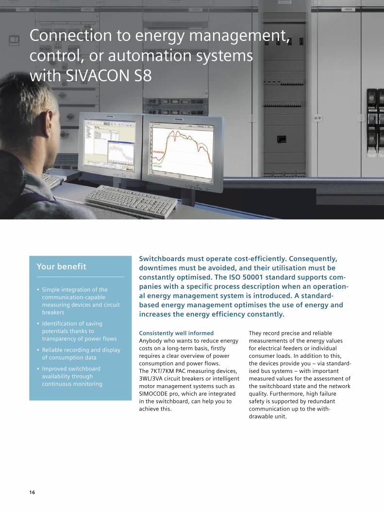
Connection to energy management, control, or automation systems with SIVACON S8
Switchboards must operate cost-efficiently. Consequently, downtimes must be avoided, and their utilisation must be constantly optimised. The ISO 50001 standard supports com-panies with a specific process description when an operation-al energy management system is introduced. A standard- based energy management optimises the use of energy and increases the energy efficiency constantly.
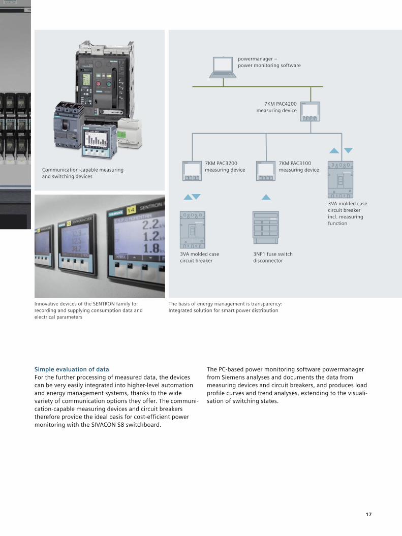
Consistently well informedAnybody who wants to reduce energy costs on a long-term basis, firstly requires a clear overview of power consumption and power flows. The 7KT/7KM PAC measuring devices, 3WL/3VA circuit breakers or intelligent motor management systems such as SIMOCODE pro, which are integrated in the switchboard, can help you to achieve this.
They record precise and reliable measurements of the energy values for electrical feeders or individual consumer loads. In addition to this, the devices provide you – via standard-ised bus systems – with important measured values for the assessment of the switchboard state and the network quality. Furthermore, high failure safety is supported by redundant communication up to the with- drawable unit.
Your benefit
• Simple integration of the communication-capable measuring devices and circuit breakers
• Identification of saving potentials thanks to transparency of power flows
• Reliable recording and display of consumption data
• Improved switchboard availability through continuous monitoring
17
Innovative devices of the SENTRON family for recording and supplying consumption data and electrical parameters
Communication-capable measuring and switching devices
The basis of energy management is transparency: Integrated solution for smart power distribution
Simple evaluation of dataFor the further processing of measured data, the devices can be very easily integrated into higher-level automation and energy management systems, thanks to the wide variety of communication options they offer. The communi-cation-capable measuring devices and circuit breakers therefore provide the ideal basis for cost-efficient power monitoring with the SIVACON S8 switchboard.
The PC-based power monitoring software powermanager from Siemens analyses and documents the data from measuring devices and circuit breakers, and produces load profile curves and trend analyses, extending to the visuali- sation of switching states.
powermanager – power monitoring software
7KM PAC3200 measuring device
3VA molded case circuit breaker
3NP1 fuse switch disconnector
7KM PAC3100 measuring device
3VA molded case circuit breaker incl. measuring function
7KM PAC4200 measuring device
18
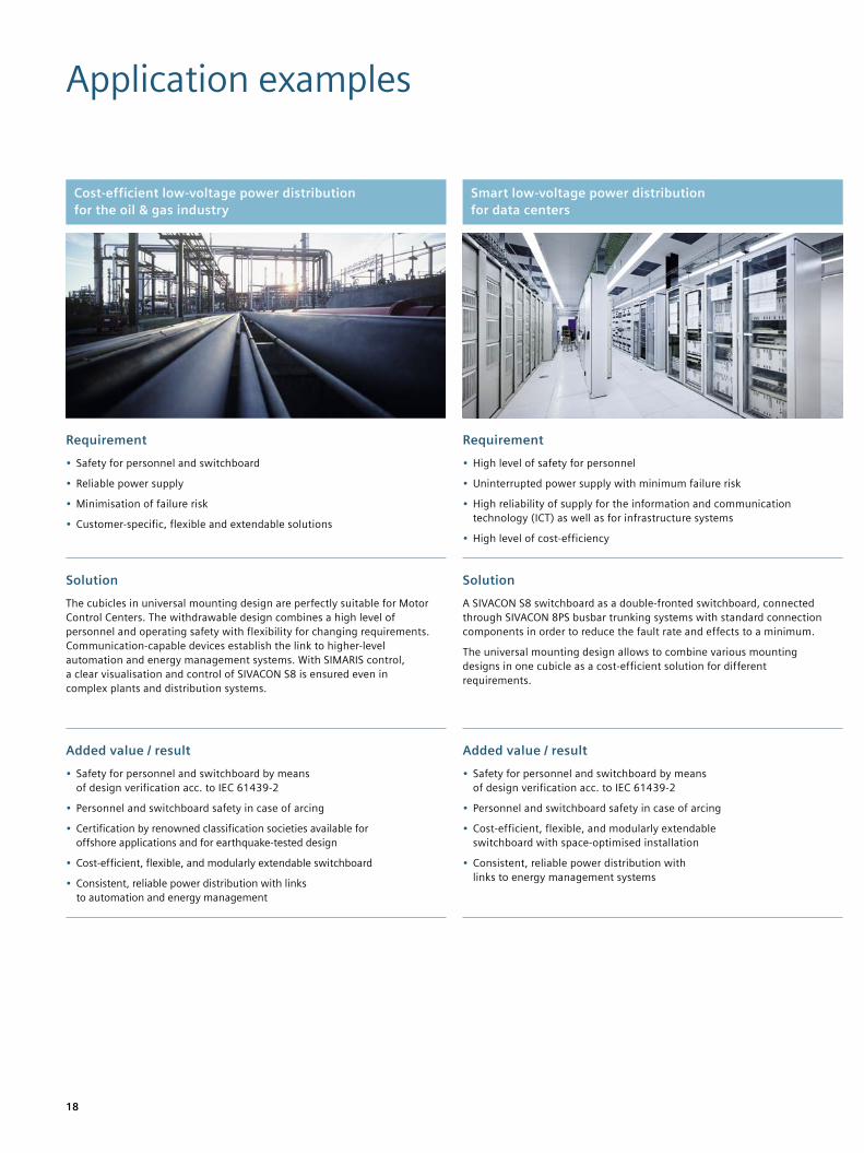
Application examples
Cost-efficient low-voltage power distribution for the oil & gas industry
Smart low-voltage power distribution for data centers
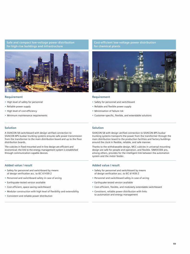
Safe and compact low-voltage power distribution for high-rise buildings and infrastructure
Cost-efficient low-voltage power distribution for chemical plants
Requirement• Safety for personnel and switchboard
• Reliable power supply
• Minimisation of failure risk
• Customer-specific, flexible and extendable solutions
Requirement• High level of safety for personnel
• Uninterrupted power supply with minimum failure risk
• High reliability of supply for the information and communication technology (ICT) as well as for infrastructure systems
• High level of cost-efficiency
Requirement• High level of safety for personnel
• Reliable power supply
• High level of cost-efficiency
• Minimum maintenance requirements
Requirement• Safety for personnel and switchboard
• Reliable and flexible power supply
• Minimisation of failure risk
• Customer-specific, flexible, and extendable solutions
SolutionThe cubicles in universal mounting design are perfectly suitable for Motor Control Centers. The withdrawable design combines a high level of personnel and operating safety with flexibility for changing requirements. Communication-capable devices establish the link to higher-level automation and energy management systems. With SIMARIS control, a clear visualisation and control of SIVACON S8 is ensured even in complex plants and distribution systems.
SolutionA SIVACON S8 switchboard as a double-fronted switchboard, connected through SIVACON 8PS busbar trunking systems with standard connection components in order to reduce the fault rate and effects to a minimum.
The universal mounting design allows to combine various mounting designs in one cubicle as a cost-efficient solution for different requirements.
SolutionA SIVACON S8 switchboard with design verified connection to SIVACON 8PS busbar trunking systems ensures safe power transmission from the transformer to the main distribution board and up to the floor distribution boards.
The cubicles in fixed-mounted and in-line design are efficient and economical; the link to the energy management system is established through communication-capable devices.
SolutionSIVACON S8 with design verified connection to SIVACON 8PS busbar trunking systems transports the power from the transformer through the main distribution board to the production facilities and factory buildings around the clock in flexible, reliable, and safe manner.
Thanks to the withdrawable design, MCC cubicles in universal mounting design are safe for people and operation, and flexible. SIMOCODE pro, among others, provides for the intelligent link between the automation system and the motor feeder.
Added value / result• Safety for personnel and switchboard by means
of design verification acc. to IEC 61439-2
• Personnel and switchboard safety in case of arcing
• Certification by renowned classification societies available for offshore applications and for earthquake-tested design
• Cost-efficient, flexible, and modularly extendable switchboard
• Consistent, reliable power distribution with links to automation and energy management
Added value / result• Safety for personnel and switchboard by means
of design verification acc. to IEC 61439-2
• Personnel and switchboard safety in case of arcing
• Cost-efficient, flexible, and modularly extendable switchboard with space-optimised installation
• Consistent, reliable power distribution with links to energy management systems
Added value / result• Safety for personnel and switchboard by means
of design verification acc. to IEC 61439-2
• Personnel and switchboard safety in case of arcing
• Earthquake-tested version available
• Cost-efficient, space-saving switchboard
• Modular construction with high level of flexibility and extensibility
• Consistent and reliable power distribution
Added value / result• Safety for personnel and switchboard by means
of design verification acc. to IEC 61439-2
• Personnel and switchboard safety in case of arcing
• Earthquake-tested version available
• Cost-efficient, flexible, and modularly extendable switchboard
• Consistent, reliable power distribution with links to automation and energy management
19
Cost-efficient low-voltage power distribution for the oil & gas industry
Smart low-voltage power distribution for data centers
Safe and compact low-voltage power distribution for high-rise buildings and infrastructure
Cost-efficient low-voltage power distribution for chemical plants
Requirement• Safety for personnel and switchboard
• Reliable power supply
• Minimisation of failure risk
• Customer-specific, flexible and extendable solutions
Requirement• High level of safety for personnel
• Uninterrupted power supply with minimum failure risk
• High reliability of supply for the information and communication technology (ICT) as well as for infrastructure systems
• High level of cost-efficiency
Requirement• High level of safety for personnel
• Reliable power supply
• High level of cost-efficiency
• Minimum maintenance requirements
Requirement• Safety for personnel and switchboard
• Reliable and flexible power supply
• Minimisation of failure risk
• Customer-specific, flexible, and extendable solutions
SolutionThe cubicles in universal mounting design are perfectly suitable for Motor Control Centers. The withdrawable design combines a high level of personnel and operating safety with flexibility for changing requirements. Communication-capable devices establish the link to higher-level automation and energy management systems. With SIMARIS control, a clear visualisation and control of SIVACON S8 is ensured even in complex plants and distribution systems.
SolutionA SIVACON S8 switchboard as a double-fronted switchboard, connected through SIVACON 8PS busbar trunking systems with standard connection components in order to reduce the fault rate and effects to a minimum.
The universal mounting design allows to combine various mounting designs in one cubicle as a cost-efficient solution for different requirements.
SolutionA SIVACON S8 switchboard with design verified connection to SIVACON 8PS busbar trunking systems ensures safe power transmission from the transformer to the main distribution board and up to the floor distribution boards.
The cubicles in fixed-mounted and in-line design are efficient and economical; the link to the energy management system is established through communication-capable devices.
SolutionSIVACON S8 with design verified connection to SIVACON 8PS busbar trunking systems transports the power from the transformer through the main distribution board to the production facilities and factory buildings around the clock in flexible, reliable, and safe manner.
Thanks to the withdrawable design, MCC cubicles in universal mounting design are safe for people and operation, and flexible. SIMOCODE pro, among others, provides for the intelligent link between the automation system and the motor feeder.
Added value / result• Safety for personnel and switchboard by means
of design verification acc. to IEC 61439-2
• Personnel and switchboard safety in case of arcing
• Certification by renowned classification societies available for offshore applications and for earthquake-tested design
• Cost-efficient, flexible, and modularly extendable switchboard
• Consistent, reliable power distribution with links to automation and energy management
Added value / result• Safety for personnel and switchboard by means
of design verification acc. to IEC 61439-2
• Personnel and switchboard safety in case of arcing
• Cost-efficient, flexible, and modularly extendable switchboard with space-optimised installation
• Consistent, reliable power distribution with links to energy management systems
Added value / result• Safety for personnel and switchboard by means
of design verification acc. to IEC 61439-2
• Personnel and switchboard safety in case of arcing
• Earthquake-tested version available
• Cost-efficient, space-saving switchboard
• Modular construction with high level of flexibility and extensibility
• Consistent and reliable power distribution
Added value / result• Safety for personnel and switchboard by means
of design verification acc. to IEC 61439-2
• Personnel and switchboard safety in case of arcing
• Earthquake-tested version available
• Cost-efficient, flexible, and modularly extendable switchboard
• Consistent, reliable power distribution with links to automation and energy management
20
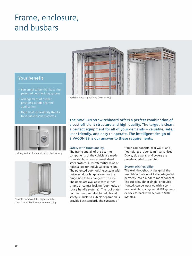
Frame, enclosure, and busbars
The SIVACON S8 switchboard offers a perfect combination of a cost-efficient structure and high quality. The target is clear: a perfect equipment for all of your demands – versatile, safe, user-friendly, and easy to operate. The intelligent design of SIVACON S8 is our answer to these requirements.
Safety with functionalityThe frame and all of the bearing components of the cubicle are made from stable, screw-fastened sheet steel profiles. Circumferential rows of holes allow for individual expansion. The patented door locking system with universal door hinge allows for the hinge side to be changed with ease. The doors are available with either simple or central locking (door locks or rotary handle systems). The roof plates feature pressure relief for additional safety. Cubicle-to-cubicle separation is provided as standard. The surfaces of
frame components, rear walls, and floor plates are sendzimir-galvanised. Doors, side walls, and covers are powder-coated or painted.
Systematic flexibilityThe well thought-out design of the switchboard allows it to be integrated perfectly into a modern room concept. The cubicles, either single- or double- fronted, can be installed with a com-mon main busbar system (MBB system), or back-to-back with separate MBB systems.
Your benefit
• Personnel safety thanks to the patented door locking system
• Arrangement of busbar positions suitable for the application
• High level of flexibility thanks to variable busbar systems
Locking system for simple or central locking
Flexible framework for high stability, corrosion protection and safe earthing
Variable busbar positions (rear or top)
21
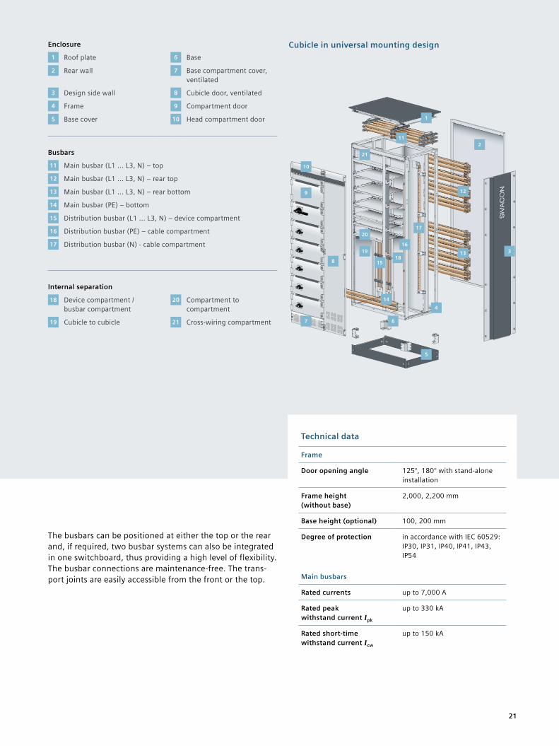
The busbars can be positioned at either the top or the rear and, if required, two busbar systems can also be integrated in one switchboard, thus providing a high level of flexibility. The busbar connections are maintenance-free. The trans-port joints are easily accessible from the front or the top.
Cubicle in universal mounting design
10
9
7
8
6
5
14
1518
16
17
11
1
12
13
4
3
2
19
20
21
Technical data
Frame
Door opening angle 125°, 180° with stand-alone installation
Frame height (without base)
2,000, 2,200 mm
Base height (optional) 100, 200 mm
Degree of protection in accordance with IEC 60529: IP30, IP31, IP40, IP41, IP43, IP54
Main busbars
Rated currents up to 7,000 A
Rated peak withstand current Ipk
up to 330 kA
Rated short-time withstand current Icw
up to 150 kA
Enclosure
1 Roof plate 6 Base
2 Rear wall 7 Base compartment cover, ventilated
3 Design side wall 8 Cubicle door, ventilated
4 Frame 9 Compartment door
5 Base cover 10 Head compartment door
Busbars
11 Main busbar (L1 ... L3, N) – top
12 Main busbar (L1 ... L3, N) – rear top
13 Main busbar (L1 ... L3, N) – rear bottom
14 Main busbar (PE) – bottom
15 Distribution busbar (L1 ... L3, N) – device compartment
16 Distribution busbar (PE) – cable compartment
17 Distribution busbar (N) - cable compartment
Internal separation
18 Device compartment / busbar compartment
20 Compartment to compartment
19 Cubicle to cubicle 21 Cross-wiring compartment
22
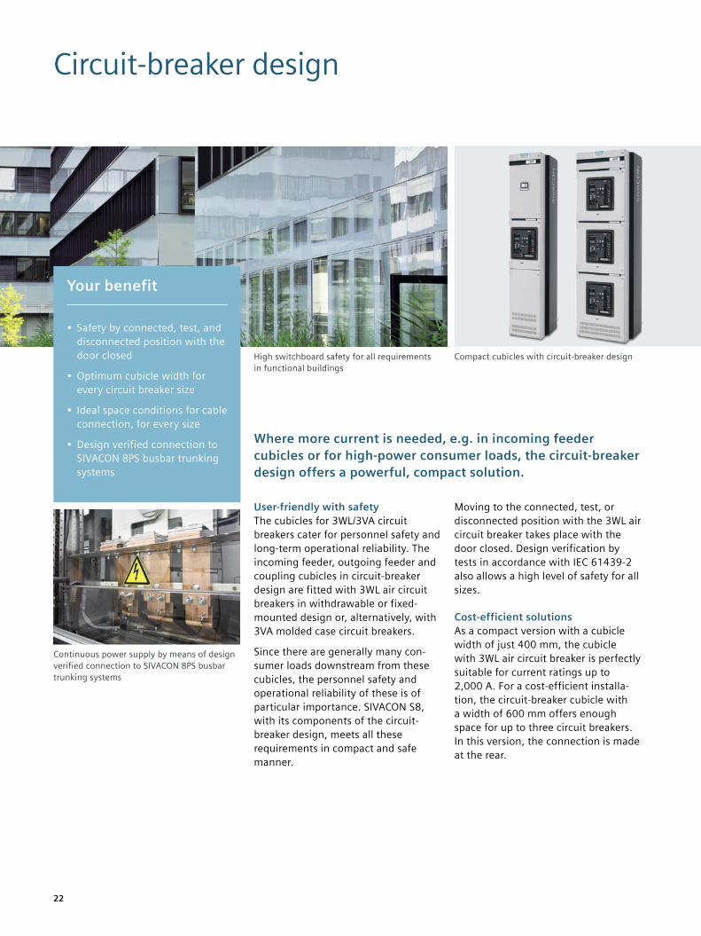
Circuit-breaker design
Where more current is needed, e.g. in incoming feeder cubicles or for high-power consumer loads, the circuit-breaker design offers a powerful, compact solution.
User-friendly with safetyThe cubicles for 3WL/3VA circuit breakers cater for personnel safety and long-term operational reliability. The incoming feeder, outgoing feeder and coupling cubicles in circuit-breaker design are fitted with 3WL air circuit breakers in withdrawable or fixed- mounted design or, alternatively, with 3VA molded case circuit breakers.
Since there are generally many con-sumer loads downstream from these cubicles, the personnel safety and operational reliability of these is of particular importance. SIVACON S8, with its components of the circuit- breaker design, meets all these requirements in compact and safe manner.
Moving to the connected, test, or disconnected position with the 3WL air circuit breaker takes place with the door closed. Design verification by tests in accordance with IEC 61439-2 also allows a high level of safety for all sizes.
Cost-efficient solutionsAs a compact version with a cubicle width of just 400 mm, the cubicle with 3WL air circuit breaker is perfectly suitable for current ratings up to 2,000 A. For a cost-efficient installa-tion, the circuit-breaker cubicle with a width of 600 mm offers enough space for up to three circuit breakers. In this version, the connection is made at the rear.
Compact cubicles with circuit-breaker designHigh switchboard safety for all requirements in functional buildings
Your benefit
• Safety by connected, test, and disconnected position with the door closed
• Optimum cubicle width for every circuit breaker size
• Ideal space conditions for cable connection, for every size
• Design verified connection to SIVACON 8PS busbar trunking systems
Continuous power supply by means of design verified connection to SIVACON 8PS busbar trunking systems
23
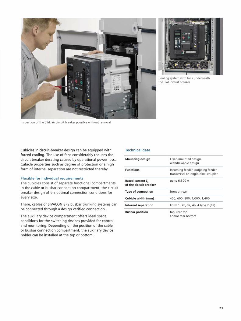
Cubicles in circuit-breaker design can be equipped with forced cooling. The use of fans considerably reduces the circuit breaker derating caused by operational power loss. Cubicle properties such as degree of protection or a high form of internal separation are not restricted thereby.
Flexible for individual requirementsThe cubicles consist of separate functional compartments. In the cable or busbar connection compartment, the circuit- breaker design offers optimal connection conditions for every size.
There, cables or SIVACON 8PS busbar trunking systems can be connected through a design verified connection.
The auxiliary device compartment offers ideal space conditions for the switching devices provided for control and monitoring. Depending on the position of the cable or busbar connection compartment, the auxiliary device holder can be installed at the top or bottom.
Technical data
Mounting design Fixed-mounted design, withdrawable design
Functions Incoming feeder, outgoing feeder, transversal or longitudinal coupler
Rated current In of the circuit breaker
up to 6,300 A
Type of connection front or rear
Cubicle width (mm) 400, 600, 800, 1,000, 1,400
Internal separation Form 1, 2b, 3a, 4b, 4 type 7 (BS)
Busbar position top, rear top and/or rear bottom
Cooling system with fans underneath the 3WL circuit breaker
Inspection of the 3WL air circuit breaker possible without removal
24
Universal mounting design
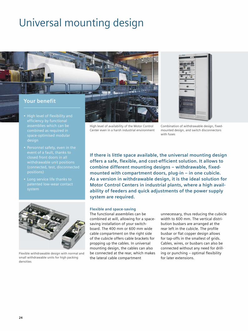
If there is little space available, the universal mounting design offers a safe, flexible, and cost-efficient solution. It allows to combine different mounting designs – withdrawable, fixed- mounted with compartment doors, plug-in – in one cubicle. As a version in withdrawable design, it is the ideal solution for Motor Control Centers in industrial plants, where a high avail-ability of feeders and quick adjustments of the power supply system are required.
Flexible and space-savingThe functional assemblies can be combined at will, allowing for a space- saving installation of your switch-board. The 400 mm or 600 mm wide cable compartment on the right side of the cubicle offers cable brackets for propping up the cables. In universal mounting design, the cables can also be connected at the rear, which makes the lateral cable compartment
unnecessary, thus reducing the cubicle width to 600 mm. The vertical distri-bution busbars are arranged at the rear left in the cubicle. The profile busbar or flat copper design allows for tap-offs in the smallest of grids. Cables, wires, or busbars can also be connected without any need for drill-ing or punching – optimal flexibility for later extensions.
Combination of withdrawable design, fixed- mounted design, and switch disconnectors with fuses
High level of availability of the Motor Control Center even in a harsh industrial environment
Your benefit
• High level of flexibility and efficiency by functional assemblies which can be combined as required in space-optimised modular design
• Personnel safety, even in the event of a fault, thanks to closed front doors in all withdrawable unit positions (connected, test, disconnected positions)
• Long service life thanks to patented low-wear contact system
Flexible withdrawable design with normal and small withdrawable units for high packing densities
25
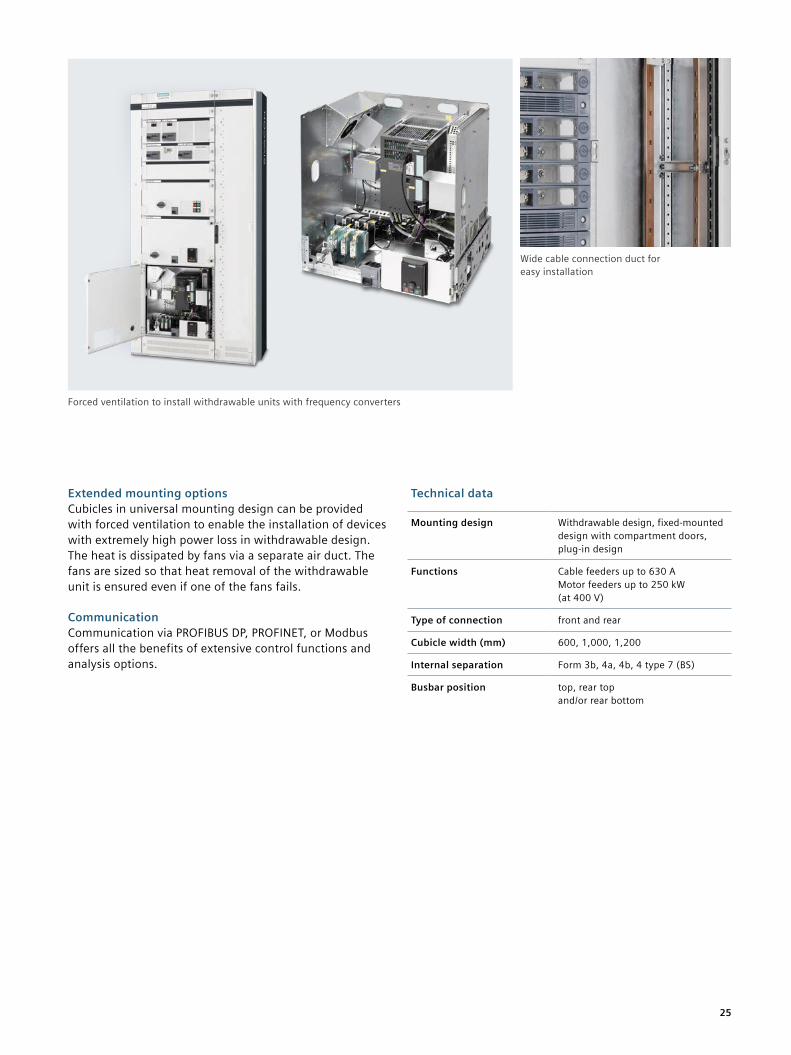
Extended mounting optionsCubicles in universal mounting design can be provided with forced ventilation to enable the installation of devices with extremely high power loss in withdrawable design. The heat is dissipated by fans via a separate air duct. The fans are sized so that heat removal of the withdrawable unit is ensured even if one of the fans fails.
CommunicationCommunication via PROFIBUS DP, PROFINET, or Modbus offers all the benefits of extensive control functions and analysis options.
Technical data
Mounting design Withdrawable design, fixed-mounted design with compartment doors, plug-in design
Functions Cable feeders up to 630 A Motor feeders up to 250 kW (at 400 V)
Type of connection front and rear
Cubicle width (mm) 600, 1,000, 1,200
Internal separation Form 3b, 4a, 4b, 4 type 7 (BS)
Busbar position top, rear top and/or rear bottom
Wide cable connection duct for easy installation
Forced ventilation to install withdrawable units with frequency converters
26
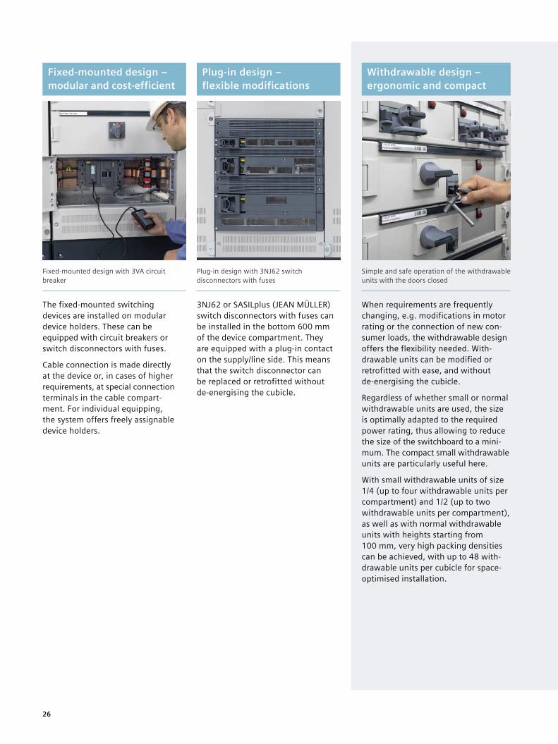
Fixed-mounted design – modular and cost-efficient
Plug-in design – flexible modifications
Withdrawable design – ergonomic and compact
Fixed-mounted design with 3VA circuit breaker
Plug-in design with 3NJ62 switch disconnectors with fuses
Simple and safe operation of the withdrawable units with the doors closed
The fixed-mounted switching devices are installed on modular device holders. These can be equipped with circuit breakers or switch disconnectors with fuses.
Cable connection is made directly at the device or, in cases of higher requirements, at special connection terminals in the cable compart-ment. For individual equipping, the system offers freely assignable device holders.
3NJ62 or SASILplus (JEAN MÜLLER) switch disconnectors with fuses can be installed in the bottom 600 mm of the device compartment. They are equipped with a plug-in contact on the supply/line side. This means that the switch disconnector can be replaced or retrofitted without de-energising the cubicle.
When requirements are frequently changing, e.g. modifications in motor rating or the connection of new con-sumer loads, the withdrawable design offers the flexibility needed. With-drawable units can be modified or retrofitted with ease, and without de-energising the cubicle.
Regardless of whether small or normal withdrawable units are used, the size is optimally adapted to the required power rating, thus allowing to reduce the size of the switchboard to a mini-mum. The compact small withdrawable units are particularly useful here.
With small withdrawable units of size 1/4 (up to four withdrawable units per compartment) and 1/2 (up to two withdrawable units per compartment), as well as with normal withdrawable units with heights starting from 100 mm, very high packing densities can be achieved, with up to 48 with-drawable units per cubicle for space- optimised installation.
27
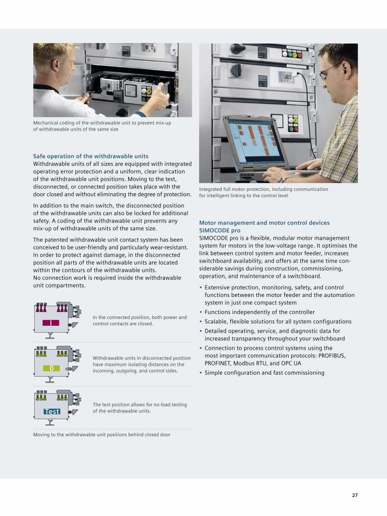
Safe operation of the withdrawable unitsWithdrawable units of all sizes are equipped with integrated operating error protection and a uniform, clear indication of the withdrawable unit positions. Moving to the test, disconnected, or connected position takes place with the door closed and without eliminating the degree of protection.
In addition to the main switch, the disconnected position of the withdrawable units can also be locked for additional safety. A coding of the withdrawable unit prevents any mix-up of withdrawable units of the same size.
The patented withdrawable unit contact system has been conceived to be user-friendly and particularly wear-resistant. In order to protect against damage, in the disconnected position all parts of the withdrawable units are located within the contours of the withdrawable units. No connection work is required inside the withdrawable unit compartments.
IIn the connected position, both power and control contacts are closed.
0Withdrawable units in disconnected position have maximum isolating distances on the incoming, outgoing, and control sides.
TestThe test position allows for no-load testing of the withdrawable units.
Moving to the withdrawable unit positions behind closed door
Mechanical coding of the withdrawable unit to prevent mix-up of withdrawable units of the same size
Integrated full motor protection, including communication for intelligent linking to the control level
Motor management and motor control devices SIMOCODE proSIMOCODE pro is a flexible, modular motor management system for motors in the low-voltage range. It optimises the link between control system and motor feeder, increases switchboard availability, and offers at the same time con-siderable savings during construction, commissioning, operation, and maintenance of a switchboard.
• Extensive protection, monitoring, safety, and control functions between the motor feeder and the automation system in just one compact system
• Functions independently of the controller• Scalable, flexible solutions for all system configurations• Detailed operating, service, and diagnostic data for
increased transparency throughout your switchboard• Connection to process control systems using the
most important communication protocols: PROFIBUS, PROFINET, Modbus RTU, and OPC UA
• Simple configuration and fast commissioning
28
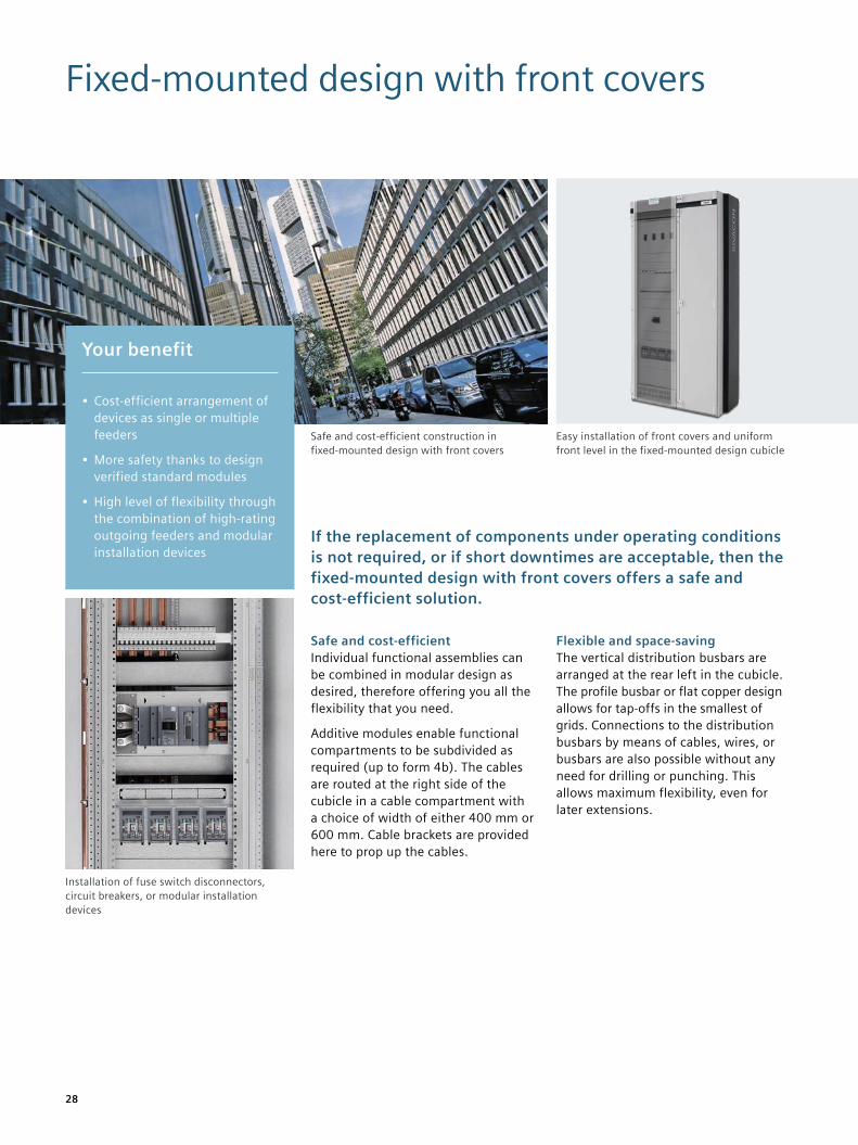
Fixed-mounted design with front covers
If the replacement of components under operating conditions is not required, or if short downtimes are acceptable, then the fixed-mounted design with front covers offers a safe and cost-efficient solution.
Safe and cost-efficientIndividual functional assemblies can be combined in modular design as desired, therefore offering you all the flexibility that you need.
Additive modules enable functional compartments to be subdivided as required (up to form 4b). The cables are routed at the right side of the cubicle in a cable compartment with a choice of width of either 400 mm or 600 mm. Cable brackets are provided here to prop up the cables.
Flexible and space-savingThe vertical distribution busbars are arranged at the rear left in the cubicle. The profile busbar or flat copper design allows for tap-offs in the smallest of grids. Connections to the distribution busbars by means of cables, wires, or busbars are also possible without any need for drilling or punching. This allows maximum flexibility, even for later extensions.
Easy installation of front covers and uniform front level in the fixed-mounted design cubicle
Safe and cost-efficient construction in fixed-mounted design with front covers
Your benefit
• Cost-efficient arrangement of devices as single or multiple feeders
• More safety thanks to design verified standard modules
• High level of flexibility through the combination of high-rating outgoing feeders and modular installation devices
Installation of fuse switch disconnectors, circuit breakers, or modular installation devices
29
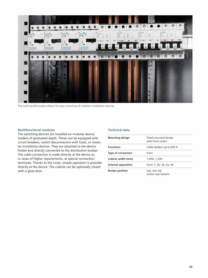
Multifunctional modulesThe switching devices are installed on modular device holders of graduated depth. These can be equipped with circuit breakers, switch disconnectors with fuses, or modu-lar installation devices. They are attached to the device holder and directly connected to the distribution busbar. The cable connection is made directly at the device or, in cases of higher requirements, at special connection terminals. Thanks to the cover, simple operation is possible directly at the device. The cubicle can be optionally closed with a glass door.
The multi-profile busbar allows for easy mounting of modular installation devices.
Technical data
Mounting design Fixed-mounted design with front covers
Functions Cable feeders up to 630 A
Type of connection front
Cubicle width (mm) 1,000, 1,200
Internal separation Form 1, 2b, 3b, 4a, 4b
Busbar position top, rear top and/or rear bottom
30
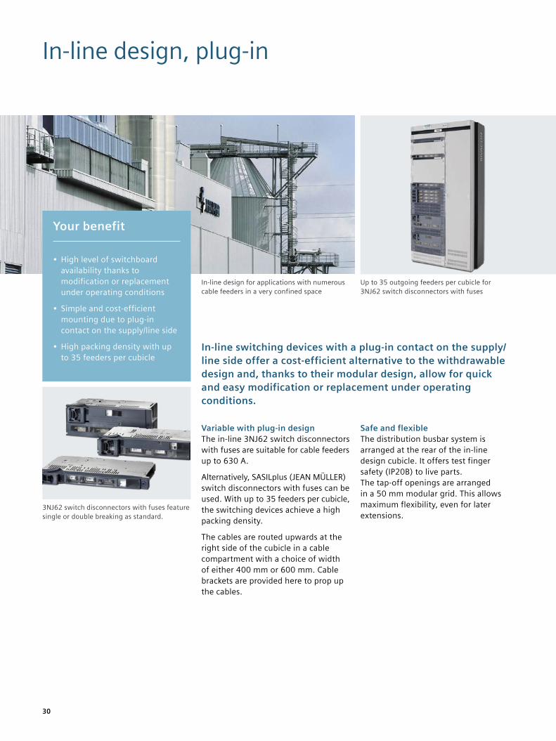
In-line design, plug-in
In-line switching devices with a plug-in contact on the supply/line side offer a cost-efficient alternative to the withdrawable design and, thanks to their modular design, allow for quick and easy modification or replacement under operating conditions.
Variable with plug-in designThe in-line 3NJ62 switch disconnectors with fuses are suitable for cable feeders up to 630 A.
Alternatively, SASILplus (JEAN MÜLLER) switch disconnectors with fuses can be used. With up to 35 feeders per cubicle, the switching devices achieve a high packing density.
The cables are routed upwards at the right side of the cubicle in a cable compartment with a choice of width of either 400 mm or 600 mm. Cable brackets are provided here to prop up the cables.
Safe and flexibleThe distribution busbar system is arranged at the rear of the in-line design cubicle. It offers test finger safety (IP20B) to live parts. The tap-off openings are arranged in a 50 mm modular grid. This allows maximum flexibility, even for later extensions.
Your benefit
• High level of switchboard availability thanks to modification or replacement under operating conditions
• Simple and cost-efficient mounting due to plug-in contact on the supply/line side
• High packing density with up to 35 feeders per cubicle
3NJ62 switch disconnectors with fuses feature single or double breaking as standard.
Up to 35 outgoing feeders per cubicle for 3NJ62 switch disconnectors with fuses
In-line design for applications with numerous cable feeders in a very confined space
31
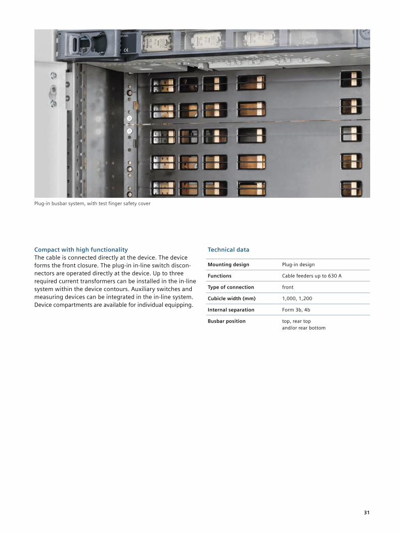
Compact with high functionalityThe cable is connected directly at the device. The device forms the front closure. The plug-in in-line switch discon-nectors are operated directly at the device. Up to three required current transformers can be installed in the in-line system within the device contours. Auxiliary switches and measuring devices can be integrated in the in-line system. Device compartments are available for individual equipping.
Plug-in busbar system, with test finger safety cover
Technical data
Mounting design Plug-in design
Functions Cable feeders up to 630 A
Type of connection front
Cubicle width (mm) 1,000, 1,200
Internal separation Form 3b, 4b
Busbar position top, rear top and/or rear bottom
32
In-line design, fixed-mounted
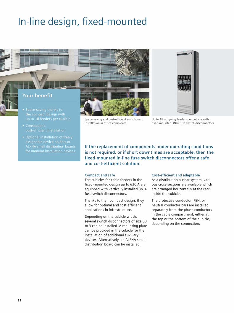
If the replacement of components under operating conditions is not required, or if short downtimes are acceptable, then the fixed-mounted in-line fuse switch disconnectors offer a safe and cost-efficient solution.
Compact and safeThe cubicles for cable feeders in the fixed-mounted design up to 630 A are equipped with vertically installed 3NJ4 fuse switch disconnectors.
Thanks to their compact design, they allow for optimal and cost-efficient applications in infrastructure.
Depending on the cubicle width, several switch disconnectors of size 00 to 3 can be installed. A mounting plate can be provided in the cubicle for the installation of additional auxiliary devices. Alternatively, an ALPHA small distribution board can be installed.
Cost-efficient and adaptableAs a distribution busbar system, vari-ous cross-sections are available which are arranged horizontally at the rear inside the cubicle.
The protective conductor, PEN, or neutral conductor bars are installed separately from the phase conductors in the cable compartment, either at the top or the bottom of the cubicle, depending on the connection.
Your benefit
• Space-saving thanks to the compact design with up to 18 feeders per cubicle
• Consequent, cost-efficient installation
• Optional installation of freely assignable device holders or ALPHA small distribution boards for modular installation devices
Up to 18 outgoing feeders per cubicle with fixed-mounted 3NJ4 fuse switch disconnectors
Space-saving and cost-efficient switchboard installation in office complexes
33
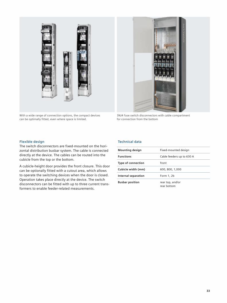
Flexible designThe switch disconnectors are fixed-mounted on the hori-zontal distribution busbar system. The cable is connected directly at the device. The cables can be routed into the cubicle from the top or the bottom.
A cubicle-height door provides the front closure. This door can be optionally fitted with a cutout area, which allows to operate the switching devices when the door is closed. Operation takes place directly at the device. The switch disconnectors can be fitted with up to three current trans-formers to enable feeder-related measurements.
Technical data
Mounting design Fixed-mounted design
Functions Cable feeders up to 630 A
Type of connection front
Cubicle width (mm) 600, 800, 1,000
Internal separation Form 1, 2b
Busbar position rear top, and/or rear bottom
3NJ4 fuse switch disconnectors with cable compartment for connection from the bottom
With a wide range of connection options, the compact devices can be optimally fitted, even where space is limited.
34
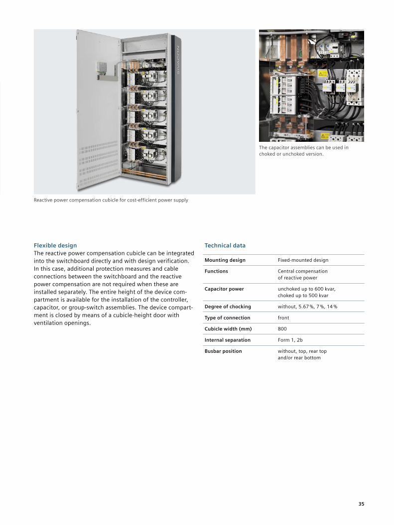
Reactive power compensation
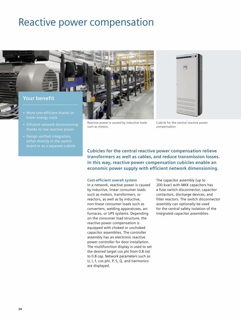
Cubicles for the central reactive power compensation relieve transformers as well as cables, and reduce transmission losses. In this way, reactive power compensation cubicles enable an economic power supply with efficient network dimensioning.
Cost-efficient overall systemIn a network, reactive power is caused by inductive, linear consumer loads such as motors, transformers, or reactors, as well as by inductive, non-linear consumer loads such as converters, welding apparatuses, arc furnaces, or UPS systems. Depending on the consumer load structure, the reactive power compensation is equipped with choked or unchoked capacitor assemblies. The controller assembly has an electronic reactive power controller for door installation. The multifunction display is used to set the desired target cos phi from 0.8 ind to 0.8 cap. Network parameters such as U, l, f, cos phi, P, S, Q, and harmonics are displayed.
The capacitor assembly (up to 200 kvar) with MKK capacitors has a fuse switch disconnector, capacitor contactors, discharge devices, and filter reactors. The switch disconnector assembly can optionally be used for the central safety isolation of the integrated capacitor assemblies.
Your benefit
• More cost-efficient thanks to lower energy costs
• Efficient network dimensioning thanks to low reactive power
• Design verified integration, either directly to the switch-board or as a separate cubicle
Cubicle for the central reactive power compensation
Reactive power is caused by inductive loads such as motors.
35
Flexible designThe reactive power compensation cubicle can be integrated into the switchboard directly and with design verification. In this case, additional protection measures and cable connections between the switchboard and the reactive power compensation are not required when these are installed separately. The entire height of the device com-partment is available for the installation of the controller, capacitor, or group-switch assemblies. The device compart-ment is closed by means of a cubicle-height door with ventilation openings.
Technical data
Mounting design Fixed-mounted design
Functions Central compensation of reactive power
Capacitor power unchoked up to 600 kvar, choked up to 500 kvar
Degree of chocking without, 5.67 %, 7 %, 14 %
Type of connection front
Cubicle width (mm) 800
Internal separation Form 1, 2b
Busbar position without, top, rear top and/or rear bottom
Reactive power compensation cubicle for cost-efficient power supply
The capacitor assemblies can be used in choked or unchoked version.
36
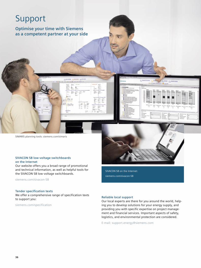
SupportOptimise your time with Siemens as a competent partner at your side
SIVACON S8 low-voltage switchboards on the InternetOur website offers you a broad range of promotional and technical information, as well as helpful tools for the SIVACON S8 low-voltage switchboards.
siemens.com/sivacon-S8
Tender specification textsWe offer a comprehensive range of specification texts to support you:
siemens.com/specification
Reliable local supportOur local experts are there for you around the world, help-ing you to develop solutions for your energy supply, and providing you with specific expertise on project manage-ment and financial services. Important aspects of safety, logistics, and environmental protection are considered.
E-mail: [email protected]
SIVACON S8 on the Internet:
siemens.com/sivacon-S8
SIMARIS planning tools: siemens.com/simaris
37
Technical experts from TIP Consultant Support offer sup-port, especially for planning and conception of electrical power distribution systems. The support also includes planning tools, specification texts, as well as planning and application manuals.
siemens.com/tip-cs
Efficient planning support with the SIMARIS software toolsPlanning electric power distribution for industrial plants, infrastructure, and buildings is becoming more and more complex. To help electrical planning engineers to work faster and better under existing conditions, the innovative SIMARIS software tools effectively support the planning process.
SIMARIS designFor network calculations and dimensioning, SIMARIS design offers a secure solution from the broad product portfolio of power distribution, according to recognised rules and standards (VDE, IEC), and specific requirements. The specif-ic components that are required are selected automatically on the basis of the given project structure and the basic data collected.
siemens.com/simaris
SIMARIS projectThis software tool enables you to create project documents quickly, easily, and clearly to fit the space and budget requirements of your complete power distribution system. Based on the switchboards and devices determined, you can also create a list of specifications in GAEB D81 or RTF format – in German, English, or Italian – at the click of a button. The relevant specification texts are stored for all the components, configured automatically, and com-piled in a project-specific manner.
siemens.com/simarisproject
Technical documentation on the InternetYou will find an overview of the technical documentation available for the SIVACON S8 low-voltage switchboard, such as the planning manual “SIVACON S8 – Technical Planning Information” on our website (updated daily) at:
siemens.com/lowvoltage/product-support
Build on a sound basisOur courses offer you solid foundations for your business success. Expert lecturers provide you with the necessary theoretical and practical information relating to our SIVACON S8 low-voltage switchboards. For details of our current range of courses, please visit our website at:
siemens.com/lowvoltage/training
SupportFor more information, please contact our Customer Support Center.
Tel.: +49 (0) 180 524 70 00 Fax: +49 (0) 180 524 24 71 (Charges depending on provider)
E-mail: [email protected]
38
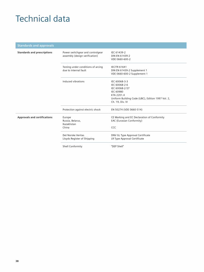
Technical data
Standards and approvals
Standards and prescriptions Power switchgear and controlgear assembly (design verification)
IEC 61439-2 DIN EN 61439-2 VDE 0660-600-2
Testing under conditions of arcing due to internal fault
IEC/TR 61641 DIN EN 61439-2 Supplement 1 VDE 0660-600-2 Supplement 1
Induced vibrations IEC 60068-3-3 IEC 60068-2-6 IEC 60068-2-57 IEC 60980 KTA 2201.4 Uniform Building Code (UBC), Edition 1997 Vol. 2, Ch. 19, Div. IV
Protection against electric shock EN 50274 (VDE 0660-514)
Approvals and certifications Europe Russia, Belarus, Kazakhstan China
CE Marking and EC Declaration of Conformity EAC (Eurasian Conformity) CCC
Det Norske Veritas Lloyds Register of Shipping
DNV GL Type Approval Certificate LR Type Approval Certificate
Shell Conformity “DEP Shell”
39
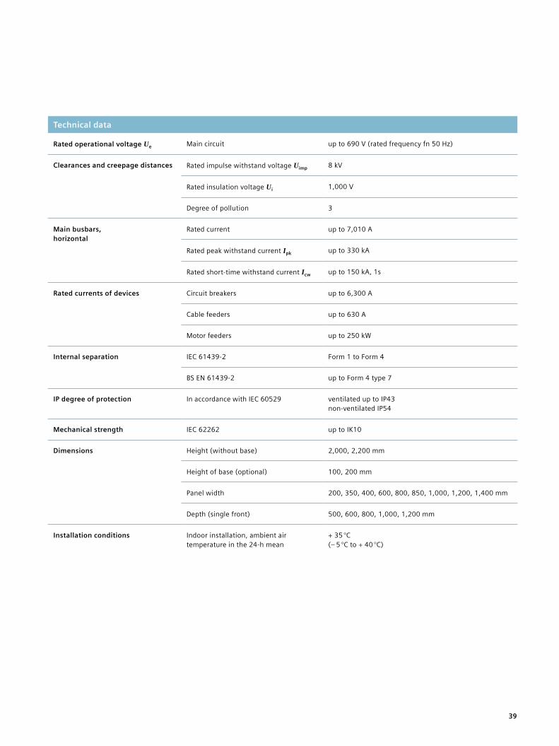
Technical data
Rated operational voltage Ue Main circuit up to 690 V (rated frequency fn 50 Hz)
Clearances and creepage distances Rated impulse withstand voltage Uimp 8 kV
Rated insulation voltage Ui 1,000 V
Degree of pollution 3
Main busbars, horizontal
Rated current up to 7,010 A
Rated peak withstand current Ipk up to 330 kA
Rated short-time withstand current Icw up to 150 kA, 1s
Rated currents of devices Circuit breakers up to 6,300 A
Cable feeders up to 630 A
Motor feeders up to 250 kW
Internal separation IEC 61439-2 Form 1 to Form 4
BS EN 61439-2 up to Form 4 type 7
IP degree of protection In accordance with IEC 60529 ventilated up to IP43 non-ventilated IP54
Mechanical strength IEC 62262 up to IK10
Dimensions Height (without base) 2,000, 2,200 mm
Height of base (optional) 100, 200 mm
Panel width 200, 350, 400, 600, 800, 850, 1,000, 1,200, 1,400 mm
Depth (single front) 500, 600, 800, 1,000, 1,200 mm
Installation conditions Indoor installation, ambient air temperature in the 24-h mean
+ 35 °C (– 5 °C to + 40 °C)
41
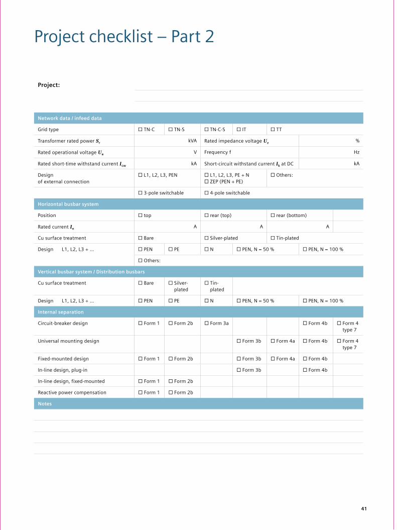
Project checklist – Part 2
Project:
Network data / infeed data
Grid type ☐ TN-C ☐ TN-S ☐ TN-C-S ☐ IT ☐ TT
Transformer rated power Sr kVA Rated impedance voltage Uz %
Rated operational voltage Ue V Frequency f Hz
Rated short-time withstand current Icw kA Short-circuit withstand current Ik at DC kA
Designof external connection
☐ L1, L2, L3, PEN ☐ L1, L2, L3, PE + N ☐ ZEP (PEN + PE)
☐ Others:
☐ 3-pole switchable ☐ 4-pole switchable
Horizontal busbar system
Position ☐ top ☐ rear (top) ☐ rear (bottom)
Rated current In A A A
Cu surface treatment ☐ Bare ☐ Silver-plated ☐ Tin-plated
Design L1, L2, L3 + … ☐ PEN ☐ PE ☐ N ☐ PEN, N = 50 % ☐ PEN, N = 100 %
☐ Others:
Vertical busbar system / Distribution busbars
Cu surface treatment ☐ Bare ☐ Silver- plated
☐ Tin- plated
Design L1, L2, L3 + … ☐ PEN ☐ PE ☐ N ☐ PEN, N = 50 % ☐ PEN, N = 100 %
Internal separation
Circuit-breaker design ☐ Form 1 ☐ Form 2b ☐ Form 3a ☐ Form 4b ☐ Form 4 type 7
Universal mounting design ☐ Form 3b ☐ Form 4a ☐ Form 4b ☐ Form 4 type 7
Fixed-mounted design ☐ Form 1 ☐ Form 2b ☐ Form 3b ☐ Form 4a ☐ Form 4b
In-line design, plug-in ☐ Form 3b ☐ Form 4b
In-line design, fixed-mounted ☐ Form 1 ☐ Form 2b
Reactive power compensation ☐ Form 1 ☐ Form 2b
Notes
40
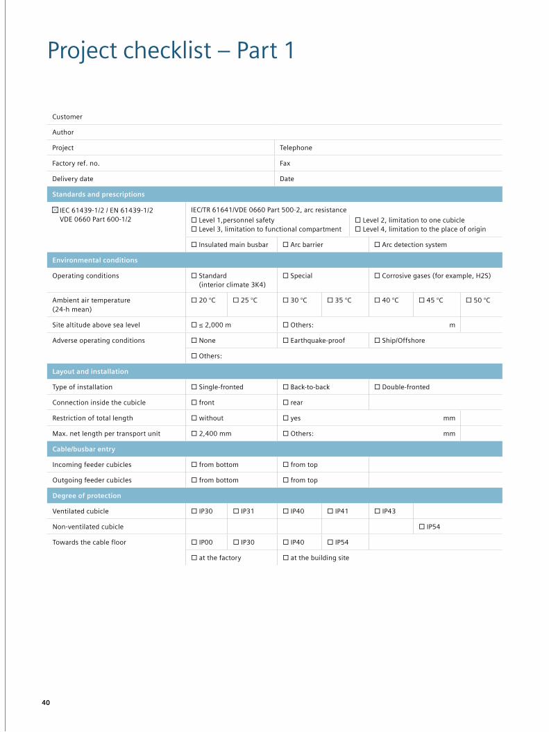
Project checklist – Part 1
Customer
Author
Project Telephone
Factory ref. no. Fax
Delivery date Date
Standards and prescriptions
IEC 61439-1/2 / EN 61439-1/2 VDE 0660 Part 600-1/2
IEC/TR 61641/VDE 0660 Part 500-2, arc resistance ☐ Level 1,personnel safety ☐ Level 3, limitation to functional compartment
☐ Level 2, limitation to one cubicle ☐ Level 4, limitation to the place of origin
☐ Insulated main busbar ☐ Arc barrier ☐ Arc detection system
Environmental conditions
Operating conditions ☐ Standard (interior climate 3K4)
☐ Special ☐ Corrosive gases (for example, H2S)
Ambient air temperature (24-h mean)
☐ 20 °C ☐ 25 °C ☐ 30 °C ☐ 35 °C ☐ 40 °C ☐ 45 °C ☐ 50 °C
Site altitude above sea level ☐ ≤ 2,000 m ☐ Others: m
Adverse operating conditions ☐ None ☐ Earthquake-proof ☐ Ship/Offshore
☐ Others:
Layout and installation
Type of installation ☐ Single-fronted ☐ Back-to-back ☐ Double-fronted
Connection inside the cubicle ☐ front ☐ rear
Restriction of total length ☐ without ☐ yes mm
Max. net length per transport unit ☐ 2,400 mm ☐ Others: mm
Cable/busbar entry
Incoming feeder cubicles ☐ from bottom ☐ from top
Outgoing feeder cubicles ☐ from bottom ☐ from top
Degree of protection
Ventilated cubicle ☐ IP30 ☐ IP31 ☐ IP40 ☐ IP41 ☐ IP43
Non-ventilated cubicle ☐ IP54
Towards the cable floor ☐ IP00 ☐ IP30 ☐ IP40 ☐ IP54
☐ at the factory ☐ at the building site
Read the QR code with the QR code reader!
Published by Siemens AG 2016
Energy Management Division Freyeslebenstrasse 1 91058 Erlangen, Germany
For more information, please contact our Customer Support Center. Tel.: +49 180 524 70 00 Fax: +49 180 524 24 71 (Charges depending on provider) E-mail: [email protected]
Article No. EMMS-B10040-00-7600 Printed in Germany Dispo 30407 TH 260-160134 BR 09162.0
Subject to changes and errors. The information given in this document only contains general descriptions and/or performance features which may not always specifically reflect those described, or which may undergo modification in the course of further development of the products. The requested performance features are binding only when they are expressly agreed upon in the concluded contract.
SIVACON® und SIMARIS® are registered trademarks of Siemens AG. Any unauthorized use is prohibited. All other designations in this document may represent trademarks whose use by third parties for their own purposes may violate the proprietary rights of the owner.