Embed Size (px)
Citation preview
Saf-T Vent® CI Plus/CI 316
For Venting Commercial & Industrial AppliancesCondensing Appliances
Category I,II,III,IV AppliancesFor Use on Positive, Neutral, and Negative Pressures up to 15" W.C.
Also For Venting Listed Gas or Oil Fired Appliances Listed as Suitable For Venting With Type L Vent Low-Temperature Venting Systems
Sizes: 4"- 32" Diameters.
Installation and Maintenance Instructions
Double Wall Special Gas Vent and Type L Vent
5030 Corporate Exchange Blvd Grand Rapids, MI 49512
Call 800 772-0739Fax 800 972-1421www.heatfab.com
Tested and Listed to UL 1738/ULC S636by Underwriters Laboratories, Inc Also Listed to UL 641, ULC/ORD-C441-M1990 and CAN-ULC-S609-M89
IMPORTANT: DO NOT INSTALL THIS PRODUCT UNTIL YOU HAVE READ AND FULLY UNDERSTAND THESE INSTALLATION INSTRUCTIONS. FAILURE TO COMPLY WITH THESE INSTRUCTIONS WILL
RESULT IN AN IMPROPER INSTALLATION AND WILL VOID ANY STATED WARRANTY.
• Examine all components for possible shipping damage prior to installation.• Proper joint assembly is essential for a safe installation. Follow these instructions exactly as written. Check severeness of joints upon completion of assembly. • This venting system must be free to expand and contract. This venting system must be supported in accordance with these instructions.• Check for unrestricted vent movement through the walls, ceilings, and roof penetrations.• All joints must be sealed with a factory adhered seal & gasket lubricant or approved seal-
ant. Reference pg 9. Allowanyfield-appliedsealanttocurefor24hoursbeforeoperatingtheappliance.• Different Manufacturers Have Different Joint Systems and Adhesives. Do Not Mix Pipe, Fittings, or Joining Methods from Different Manufacturers.
WARNING!!Failure to follow the installation instructions could cause FIRE, CARBON MONOXIDE POISONING, OR DEATH. If you are unsure of installation requirements, please call the phone number listed on the instructions or visit the website shown.
2
Table of ConTenTs
CaTegory Page
Introduction 3
Pre -Installation Considerations 3
General Installation Considerations 3
Definitions 4
Clearances to Combustibles 5
Horizontal Installations 6
Vertical Installations 7
Condensate Drains 8 SealantSpecification&Coverage 9
Joint Assembly Instructions, Straight Length 10
Joint Assembly Instructions, Rotating Clamp 12
Universal Boiler Adapter 15
Adjustable Section 16
Horizontal Support 17
Rain Cap 18
Exit Cone 19
Guy Support 20
Floor Support 23
Tall Cone Flashing 24
Pitched Roof Tall Cone Flashing 26
Wall Termination 27
Maintenance 28
3
Saf-T Vent CI Plus/CI 316 is a double wall Special Gas Vent that is UL Tested and Listed to the UL 1738 Standard. Saf-TVentCIPlus/CI316isappropriateforuseonCategoryI,II,IIIandIVgasfiredapplianceswithmaximumfluegastemperatures of 550°F. Saf-T Vent CI Plus and CI 316 components are compatible and may be combined for installa-tions. Non categorized condensing appliances and appliances that call for AL29-4C vent systems are also appropriate for Saf-T Vent CI Plus (Excludes CI 316).
Saf-T Vent CI Plus/CI 316 has been tested at 2 1/2 times its positive pressure rating of 15" W.C.
Saf-TVentModelCIPlus/CI316isalsoforusewithgasoroilfiredappliancesListedassuitableforventingwithtypeLventingsystemsandwhichitscontinuousfluegastemperaturedoesnotexceed570°F(300°C).
NOTE: CI Plus/CI 316 is also available with fiber insulation (model I-CI Plus/I-CI 316) in the annular space between the inner and outer walls. All installation requirements and instructions referenced throughout this document apply to both models. CI Plus/CI 316 and Insulated CI Plus/CI 316 parts can be interchanged and clearances to combustibles are the same for both. P/n's for I-CI Plus/I-CI 316 are ICC... for only parts conveying flue gases.
Install in accordance with these instructions and those of the appliance manufacturer. Consult the appliance manufactur-er’s instructions for the maximum horizontal length of the vent connector, as well as any restriction on total vent height, proper sizing of the vent, common venting considerations and procedures for connecting the vent to the appliance. The installation must conform to applicable NFPA/ANSI standards, as well as local codes. Contact the authority having jurisdiction prior to beginning any work to obtain any required permits.
Pre-Installation Considerations: • Proper planning prior to installation is essential as to avoid possible contact with concealed plumbing or electri-calwiringinsidewalls,floorsorceilingsaswellasmaintainingproperclearances.Besuretoplanasufficientnumber of supports for the entire system that will maintain the required straight-line pitch and hold the system in place. A continuous straight-line upward pitch of at least 1/4 inch (2 degrees) to the foot on horizontal runs must be maintained in order to properly rid the system of the corrosive condensate.
•Reference Combustion & Ventilation Air on the last page for proper air supply guidelines.
General Installation Requirements:• The appliance manufacturer's instructions take precedence over this document.• Failure to conform to any of these requirements may violate local, state, national or international codes as well as
create conditions which may cause catastrophic property damage or personal injury. Failure to conform to any of these requirements will also void any warranties, stated or implied.
• Saf-T Vent CI Plus/CI 316 vent sections, or other Saf-T Vent products, must be used throughout the entire length ofthesystem.Alternativessuchasgalvanizedpipe,PVC,nonmetallicpipe,prefabricatedchimney,field-fabricat-edventsorTypeBventsectionsmustnotbeused.Donotmixpipes,fittings,orjoiningmethodsfromdifferentmanufacturers.
•Ifcalledforbytheappliancemanufacturer’sinstructions,adrainfittingmustbelocatedascloseaspossibletotheapplianceflueoutlet.
•Alljointsmustbesealedwithafactoryadheredsealorapprovedsealant.Allowanyfield-appliedsealanttocurefor 24 hours before operating the appliance.
•Morethanoneappliancemaynotbeinterconnectedtoanypartoftheventingsystem,unlessspecificallyallowedby each of the appliance manufacturers' instructions. Under no circumstances should a natural draft appliance be interconnected with a forced draft appliance. All connected appliances must be all natural draft or all forced draft.Whenventingmultipleforceddraftappliances,precautionsmustbetakentopreventbackflowofdraft.
•Anypenetrationsofceilings,floors,orwallsmustbeproperlyfire-stopped.• The vent system shall not be routed into, through or within any other actively used vent or chimney.
4
Definitions:
AL 29-4C - A superferritic stainless steel alloy designed by Allegheny Ludlum for extreme resistance to chloride ion pitting, crevice corrosion and stress corrosion cracking. Equivalent material made by othermanufacturersmaybeidentifiedbytheUNSdesignatorS44735.
316L - An austenetic chromium-nickel stainless steel containing molybdenum. Type 316L is an extra-low carbon version of type 316 that minimizes harmful carbide precipitation due to welding. Type 316L is used in applications where immunity to carbide precipitation due to welding assures optimumcorrosionresistance.316LmaybeidentifiedbytheUNSdesignatorS31603.
Category I Appliance - An appliance which operates with a non-positive vent static pressure and with a vent gas temperature that avoids excessive condensate production in the appliance.
Category II Appliance - An appliance which operates with a non-positive vent static pressure and with a vent gas temperature that may cause excessive condensate production in the appliance.
Category III Appliance - An appliance that operates with a positive vent static pressure and with a vent gas temperature that avoids excessive condensate production in the appliance.
Category IV Appliance - An appliance that operates with a positive vent static pressure and with a vent gas temperature that may cause excessive condensate production in the appliance.
Condensate - The liquid that separates from the vent gases due to a reduction in temperature or increase in pressure.
Condensing Type Appliance - Any Category II or IV appliance. During start-up, some Category III appliances may also produce condensate in the vent.
Special Gas Vent - Gas vents for venting listed Category II, III, and IV, gas-burning appliances.
Type L Vent-VentsystemsforusewithgasandoilfiredappliancesListedassuitableforventingwith Type L venting systems.
UL 1738 - A standard issued by Underwriters Laboratories that covers the requirements for venting systems intended for use on Category II, III, or IV gas- burning appliances.
Vent Connector - The vent or pipe which connects a fuel-gas burning appliance to a vent or chimney.
5
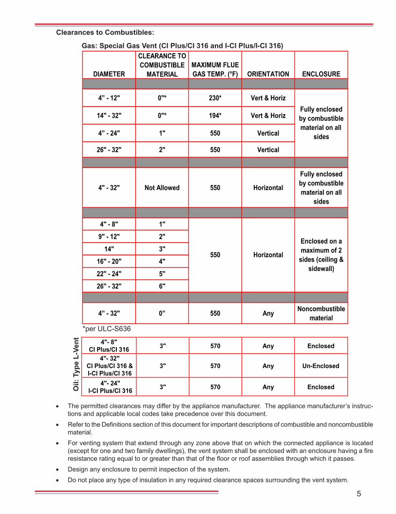
Clearances to Combustibles:
Gas: Special Gas Vent (CI Plus/CI 316 and I-CI Plus/I-CI 316)
Oil:
Typ
e L-
Vent
• The permitted clearances may differ by the appliance manufacturer. The appliance manufacturer’s instruc-tions and applicable local codes take precedence over this document.
• RefertotheDefinitionssectionofthisdocumentforimportantdescriptionsofcombustibleandnoncombustiblematerial.
• For venting system that extend through any zone above that on which the connected appliance is located (exceptforoneandtwofamilydwellings),theventsystemshallbeenclosedwithanenclosurehavingafireresistanceratingequaltoorgreaterthanthatofthefloororroofassembliesthroughwhichitpasses.
• Design any enclosure to permit inspection of the system.• Do not place any type of insulation in any required clearance spaces surrounding the vent system.
*per ULC-S636
DIAMETER
CLEARANCE TO COMBUSTIBLE
MATERIALMAXIMUM FLUE GAS TEMP. (°F) ORIENTATION ENCLOSURE
4” - 12" 0"* 230* Vert & Horiz
14" - 32" 0"* 194* Vert & Horiz
4” - 24" 1" 550 Vertical
26" - 32" 2" 550 Vertical
4" - 32" Not Allowed 550 Horizontal
Fully enclosed by combustible material on all
sides
4" - 8" 1"
9" - 12" 2"
14" 3"
16" - 20" 4"
22" - 24" 5"
26" - 32" 6"
4” - 32" 0” 550 Any Noncombustible material
Enclosed on a maximum of 2
sides (ceiling & sidewall)
Horizontal550
Fully enclosed by combustible material on all
sides
4"- 8"
CI Plus/CI 316 3" 570 Any Enclosed
4"- 32" CI Plus/CI 316 &I-CI Plus/CI 316
3" 570 Any Un-Enclosed
4"- 24" I-CI Plus/CI 316 3" 570 Any Enclosed
6
4 Ft. Horizontally from Doors and Windows
4 Ft. Below any Window or üüüüüüü
1 Ft. AboveGround or Snow Line
2 Ft. AboveStructures
Within 10 Ft.
2 Ft. From & 1 Ft. Above Doors and Windows
NOT Above anyWalkway
LESS THAN 10 Ft.
3 Ft.
Forced Air Inlet
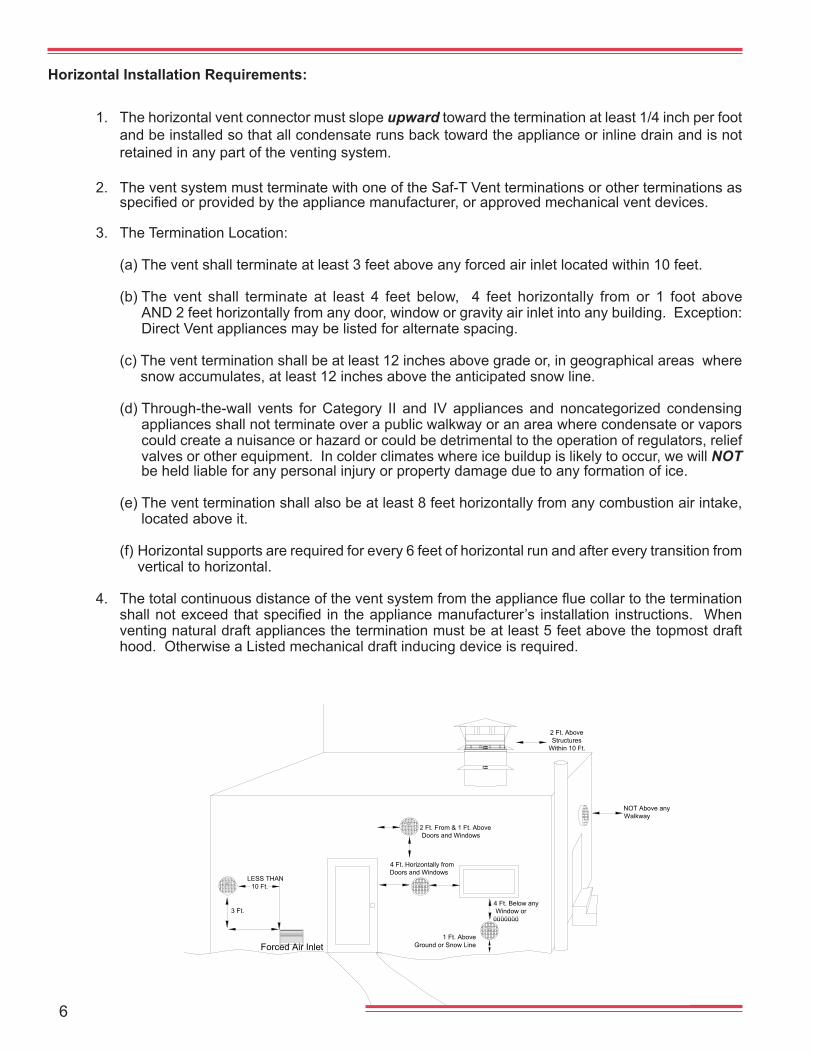
1. The horizontal vent connector must slope upward toward the termination at least 1/4 inch per foot and be installed so that all condensate runs back toward the appliance or inline drain and is not retained in any part of the venting system.
2. The vent system must terminate with one of the Saf-T Vent terminations or other terminations as specifiedorprovidedbytheappliancemanufacturer,orapprovedmechanicalventdevices.
3. The Termination Location:
(a) The vent shall terminate at least 3 feet above any forced air inlet located within 10 feet.
(b) The vent shall terminate at least 4 feet below, 4 feet horizontally from or 1 foot above AND 2 feet horizontally from any door, window or gravity air inlet into any building. Exception: Direct Vent appliances may be listed for alternate spacing.
(c) The vent termination shall be at least 12 inches above grade or, in geographical areas where snow accumulates, at least 12 inches above the anticipated snow line.
(d) Through-the-wall vents for Category II and IV appliances and noncategorized condensing
appliances shall not terminate over a public walkway or an area where condensate or vapors could create a nuisance or hazard or could be detrimental to the operation of regulators, relief valves or other equipment. In colder climates where ice buildup is likely to occur, we will NOT be held liable for any personal injury or property damage due to any formation of ice.
(e) The vent termination shall also be at least 8 feet horizontally from any combustion air intake,
located above it.
(f) Horizontal supports are required for every 6 feet of horizontal run and after every transition from vertical to horizontal.
4. Thetotalcontinuousdistanceoftheventsystemfromtheappliancefluecollartotheterminationshallnotexceedthatspecified in theappliancemanufacturer’s installation instructions. Whenventing natural draft appliances the termination must be at least 5 feet above the topmost draft hood. Otherwise a Listed mechanical draft inducing device is required.
Horizontal Installation Requirements:
7
1. The vent system must terminate at least 3 feet above the roof line and at least 2 feet higher than any portion of the building within 10 feet.
2. When terminated at a height of more than 6 feet the stack must be supported by a Saf-T Vent CI Plus/CI 316 Guy Section.
3. The vent system must terminate with one of the Saf-T Vent Terminations; except: (a) Category I or II appliances (natural draft) must use a Saf-T Vent Rain Cap with wind band.
(b) Vent systems without provisions for draining rain water must use a Saf-T Vent Rain Cap.
(c)Terminationsorapprovedmechanicalventdevicesspecifiedorprovidedbytheappliancemanufacturer are permitted.
4. Thetotalcontinuousdistanceoftheventsystemfromtheappliancefluecollartotheterminationshallnotexceedthatspecifiedintheappliancemanufacturer’sinstallationinstructions.Whenventing natural draft appliances the termination must be at least 5 feet above the topmost draft hood. Otherwise a Listed mechanical draft inducing device is required.
5. In general, systems installed in cold climates perform best, and condensation is reduced, when the system is fully enclosed by some part of the building structure. When installing into a com-bustible square or rectangular vertical chase, the Coupler Band bracket must be positioned into a corner of the chase to provide the clearance as UL listed.
6. In cold climates do not install a condensate drain on the exterior of the building. Doing so may result in dangerous icy conditions on surfaces near the drain and may cause damage to the vent system and/or the building exterior. We will NOT be held liable for any personal injury or property damage due to any formation of ice.
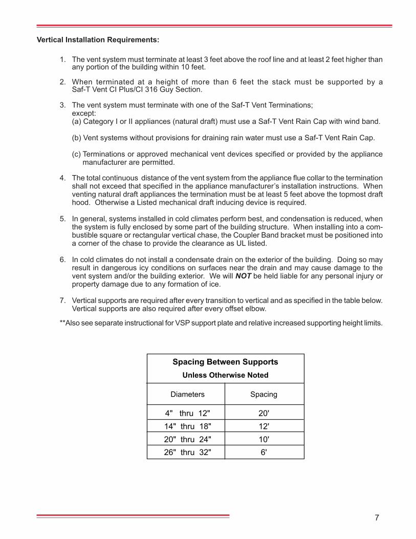
7. Verticalsupportsarerequiredaftereverytransitiontoverticalandasspecifiedinthetablebelow.Vertical supports are also required after every offset elbow.
**Also see separate instructional for VSP support plate and relative increased supporting height limits.
Vertical Installation Requirements:
Spacing Between SupportsUnless Otherwise Noted
Diameters Spacing
4" thru 12" 20' 14" thru 18" 12' 20" thru 24" 10' 26" thru 32" 6'
8
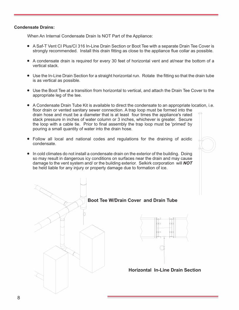
Condensate Drains:
When An Internal Condensate Drain Is NOT Part of the Appliance:
• A Saf-T Vent CI Plus/CI 316 In-Line Drain Section or Boot Tee with a separate Drain Tee Cover is stronglyrecommended.Installthisdrainfittingasclosetotheappliancefluecollaraspossible.
• A condensate drain is required for every 30 feet of horizontal vent and at/near the bottom of a vertical stack.
• UsetheIn-LineDrainSectionforastraighthorizontalrun.Rotatethefittingsothatthedraintubeis as vertical as possible.
• Use the Boot Tee at a transition from horizontal to vertical, and attach the Drain Tee Cover to the appropriate leg of the tee.
• A Condensate Drain Tube Kit is available to direct the condensate to an appropriate location, i.e. floordrainorventedsanitarysewerconnection.Atraploopmustbeformedintothedrain hose and must be a diameter that is at least four times the appliance's rated stack pressure in inches of water column or 3 inches, whichever is greater. Secure theloopwithacabletie.Priortofinalassemblythetraploopmustbe'primed'bypouring a small quantity of water into the drain hose.
• Follow all local and national codes and regulations for the draining of acidic condensate.
• In cold climates do not install a condensate drain on the exterior of the building. Doing so may result in dangerous icy conditions on surfaces near the drain and may cause damage to the vent system and/ or the building exterior. Selkirk corporation will NOT be held liable for any injury or property damage due to formation of ice.
Horizontal In-Line Drain Section
Boot Tee W/Drain Cover and Drain Tube
9
silico
ne
lubric
ant
Silicone Seal
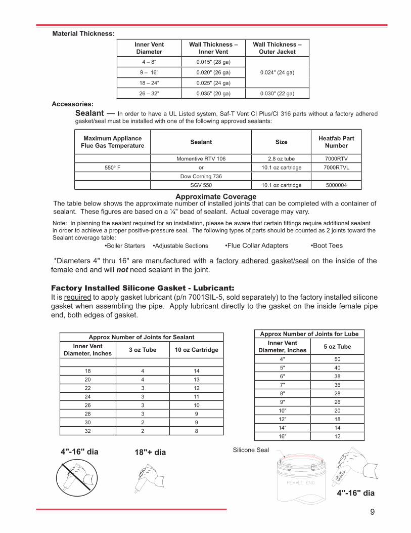
Accessories:Sealant — In order to have a UL Listed system, Saf-T Vent CI Plus/CI 316 parts without a factory adhered gasket/seal must be installed with one of the following approved sealants:
Approximate Coverage
Note:Inplanningthesealantrequiredforaninstallation,pleasebeawarethatcertainfittingsrequireadditionalsealantin order to achieve a proper positive-pressure seal. The following types of parts should be counted as 2 joints toward the Sealant coverage table: •Boiler Starters •Adjustable Sections •Flue Collar Adapters •Boot Tees
The table below shows the approximate number of installed joints that can be completed with a container of sealant.Thesefiguresarebasedona¼"beadofsealant.Actualcoveragemayvary.
*Diameters 4" thru 16" are manufactured with a factory adhered gasket/seal on the inside of the female end and will not need sealant in the joint.
Material Thickness:
It is required to apply gasket lubricant (p/n 7001SIL-5, sold separately) to the factory installed silicone gasket when assembling the pipe. Apply lubricant directly to the gasket on the inside female pipe end, both edges of gasket.
Factory Installed Silicone Gasket - Lubricant:
18"+ dia
4"-16" dia
4"-16" dia
Inner Vent Diameter
Wall Thickness – Inner Vent
Wall Thickness – Outer Jacket
4 – 8" 0.015" (28 ga)
0.024" (24 ga)9 – 16" 0.020" (26 ga)
18 – 24" 0.025" (24 ga)
26 – 32" 0.035" (20 ga) 0.030" (22 ga)
Approx Number of Joints for SealantInner Vent
Diameter, Inches 3 oz Tube 10 oz Cartridge
18 4 1420 4 1322 3 1224 3 1126 3 1028 3 930 2 932 2 8
Approx Number of Joints for LubeInner Vent
Diameter, Inches 5 oz Tube
4" 505" 406" 387" 368" 289" 26
10" 2012" 1814" 1416" 12
Maximum Appliance Flue Gas Temperature Sealant Size Heatfab Part
Number
Momentive RTV 106 2.8 oz tube 7000RTV550º F or 10.1 oz cartridge 7000RTVL
Dow Corning 736SGV 550 10.1 oz cartridge 5000004
10
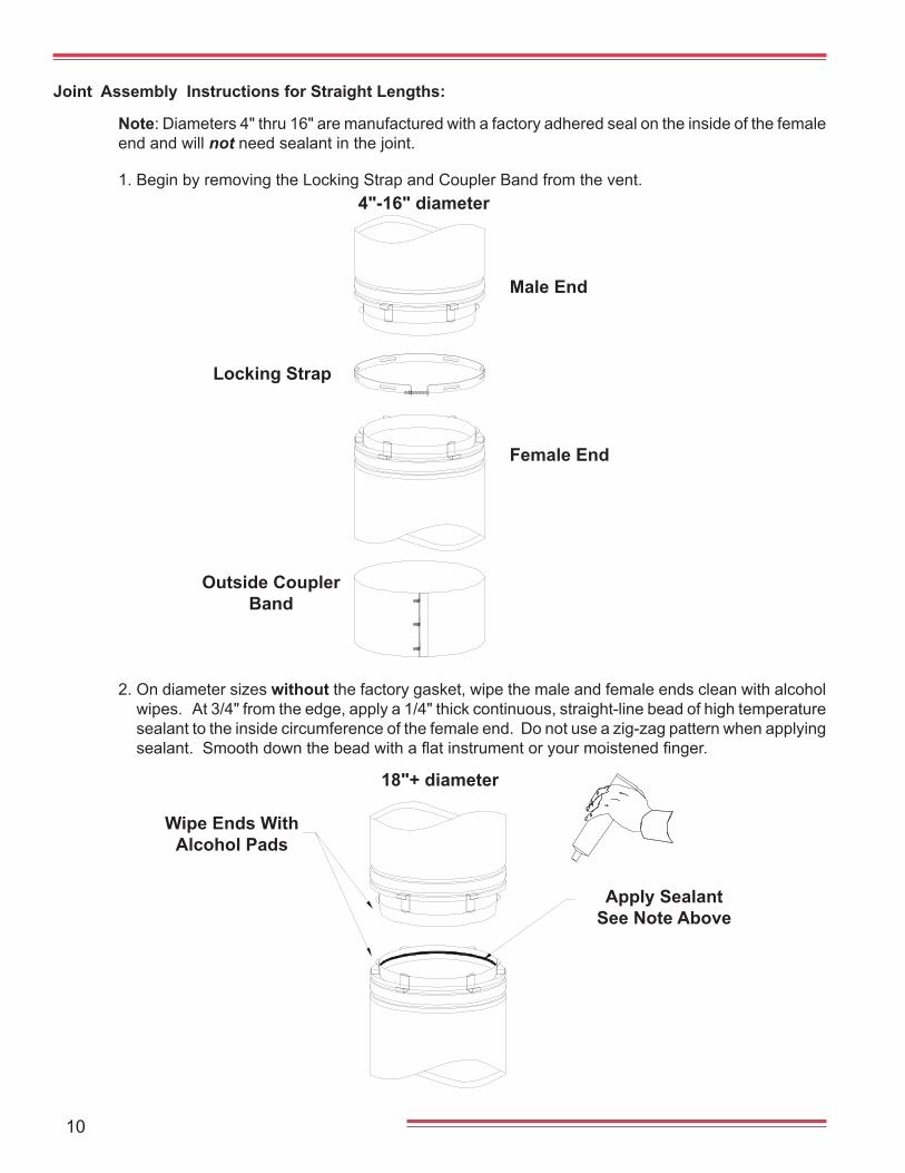
Joint Assembly Instructions for Straight Lengths:
Locking Strap
Outside Coupler Band
Female End
Male End
Wipe Ends With Alcohol Pads
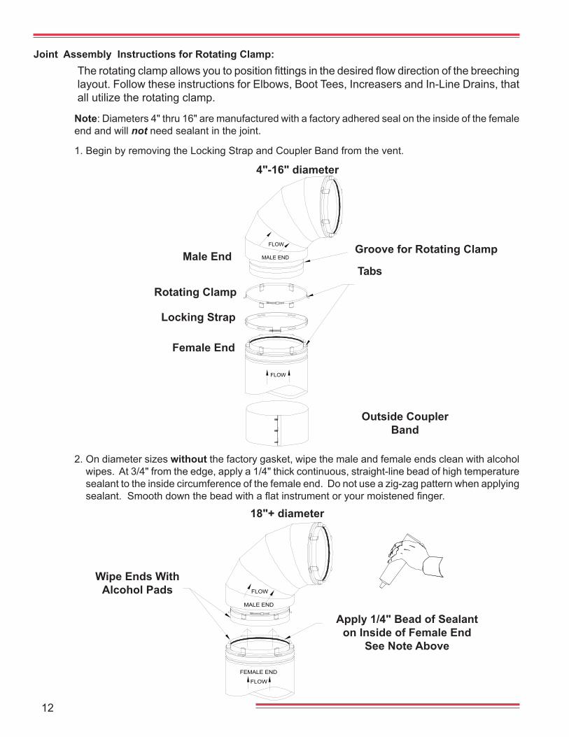
2. On diameter sizes without the factory gasket, wipe the male and female ends clean with alcohol wipes. At 3/4" from the edge, apply a 1/4" thick continuous, straight-line bead of high temperature sealant to the inside circumference of the female end. Do not use a zig-zag pattern when applying sealant.Smoothdownthebeadwithaflatinstrumentoryourmoistenedfinger.
1. Begin by removing the Locking Strap and Coupler Band from the vent.
Apply SealantSee Note Above
Note: Diameters 4" thru 16" are manufactured with a factory adhered seal on the inside of the female end and will not need sealant in the joint.
18"+ diameter
4"-16" diameter
11
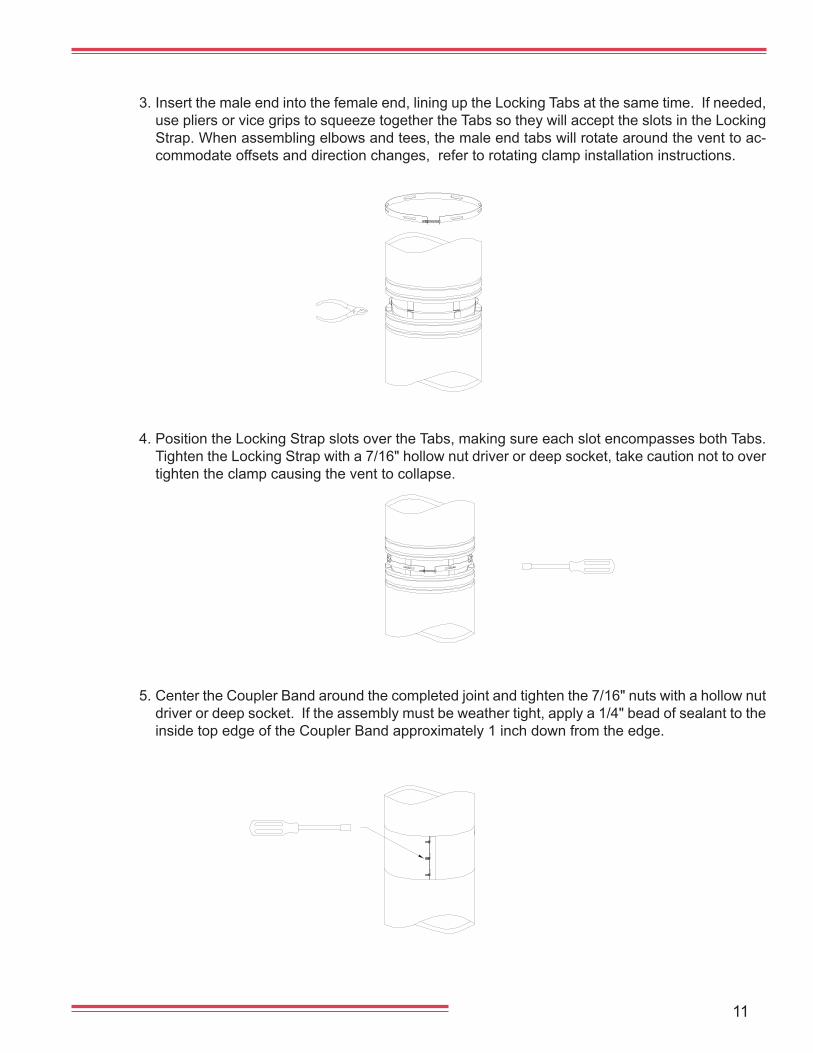
3. Insert the male end into the female end, lining up the Locking Tabs at the same time. If needed, use pliers or vice grips to squeeze together the Tabs so they will accept the slots in the Locking Strap. When assembling elbows and tees, the male end tabs will rotate around the vent to ac-commodate offsets and direction changes, refer to rotating clamp installation instructions.
5. Center the Coupler Band around the completed joint and tighten the 7/16" nuts with a hollow nut driver or deep socket. If the assembly must be weather tight, apply a 1/4" bead of sealant to the inside top edge of the Coupler Band approximately 1 inch down from the edge.
4. Position the Locking Strap slots over the Tabs, making sure each slot encompasses both Tabs. Tighten the Locking Strap with a 7/16" hollow nut driver or deep socket, take caution not to over tighten the clamp causing the vent to collapse.
12
FLOW
FEMALE END
MALE END
FLOW
Joint Assembly Instructions for Rotating Clamp:Therotatingclampallowsyoutopositionfittingsinthedesiredflowdirectionofthebreechinglayout. Follow these instructions for Elbows, Boot Tees, Increasers and In-Line Drains, that all utilize the rotating clamp.
Tabs
Outside Coupler Band
Locking Strap
Rotating Clamp
1. Begin by removing the Locking Strap and Coupler Band from the vent.
Groove for Rotating Clamp
2. On diameter sizes without the factory gasket, wipe the male and female ends clean with alcohol wipes. At 3/4" from the edge, apply a 1/4" thick continuous, straight-line bead of high temperature sealant to the inside circumference of the female end. Do not use a zig-zag pattern when applying sealant.Smoothdownthebeadwithaflatinstrumentoryourmoistenedfinger.
Apply 1/4" Bead of Sealant on Inside of Female End
See Note Above
Female End
Male End
Note: Diameters 4" thru 16" are manufactured with a factory adhered seal on the inside of the female end and will not need sealant in the joint.
MALE END
FLOW
FLOW
18"+ diameter
4"-16" diameter
Wipe Ends With Alcohol Pads
13
MALE END
FLOW
FLOW
FEMALE END
FEMALE END
FLOW
MALE END
FLOW
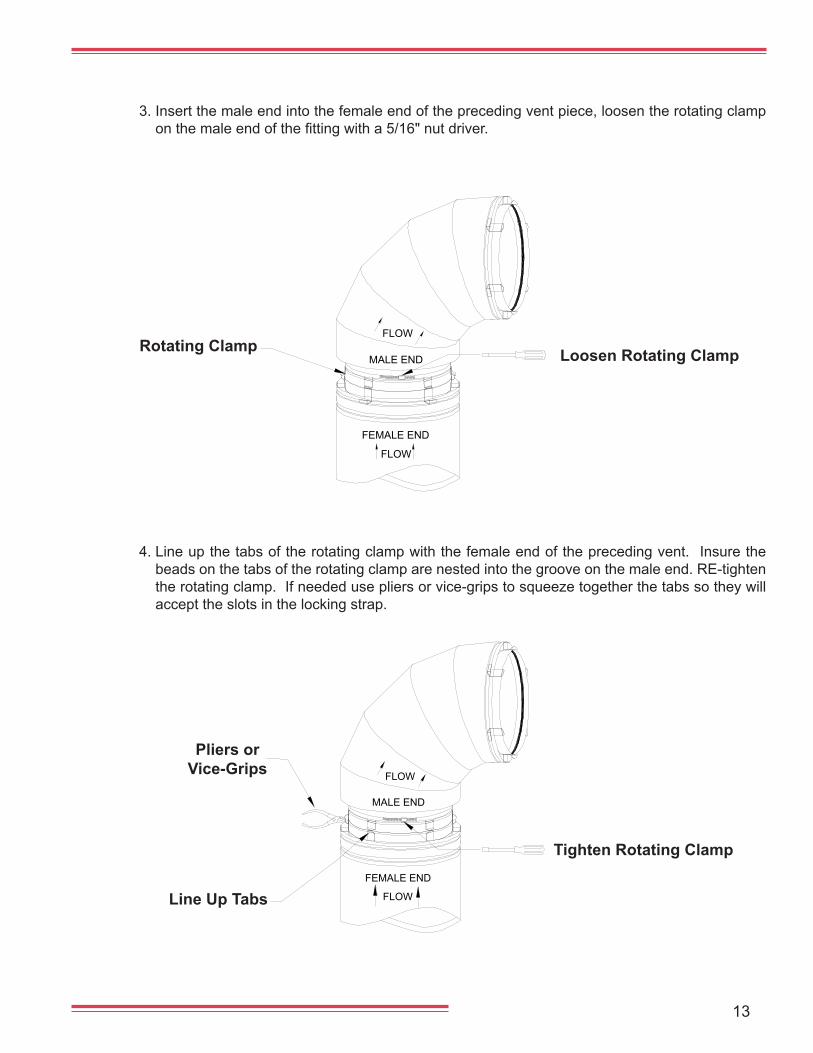
3. Insert the male end into the female end of the preceding vent piece, loosen the rotating clamp onthemaleendofthefittingwitha5/16"nutdriver.
Loosen Rotating ClampRotating Clamp
4. Line up the tabs of the rotating clamp with the female end of the preceding vent. Insure the beads on the tabs of the rotating clamp are nested into the groove on the male end. RE-tighten the rotating clamp. If needed use pliers or vice-grips to squeeze together the tabs so they will accept the slots in the locking strap.
Pliers or Vice-Grips
Line Up Tabs
Tighten Rotating Clamp
14
FEMALE END
FLOW
MALE END
FLOW
1"
FEMALE END
FLOW
FLOW
MALE END
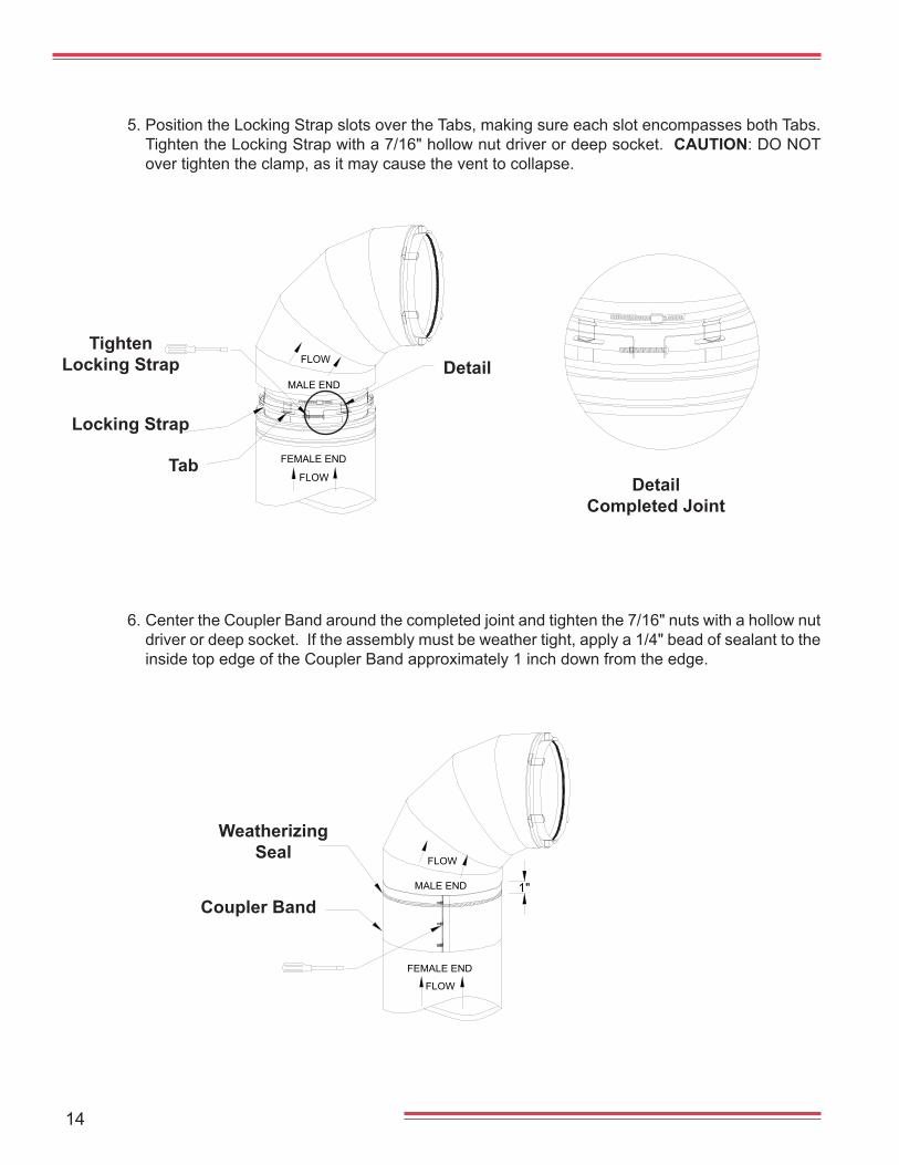
5. Position the Locking Strap slots over the Tabs, making sure each slot encompasses both Tabs. Tighten the Locking Strap with a 7/16" hollow nut driver or deep socket. CAUTION: DO NOT over tighten the clamp, as it may cause the vent to collapse.
Tab
Locking Strap
TightenLocking Strap
6. Center the Coupler Band around the completed joint and tighten the 7/16" nuts with a hollow nut driver or deep socket. If the assembly must be weather tight, apply a 1/4" bead of sealant to the inside top edge of the Coupler Band approximately 1 inch down from the edge.
Coupler Band
Weatherizing Seal
Detail
DetailCompleted Joint
15
FLOW
1" MIN
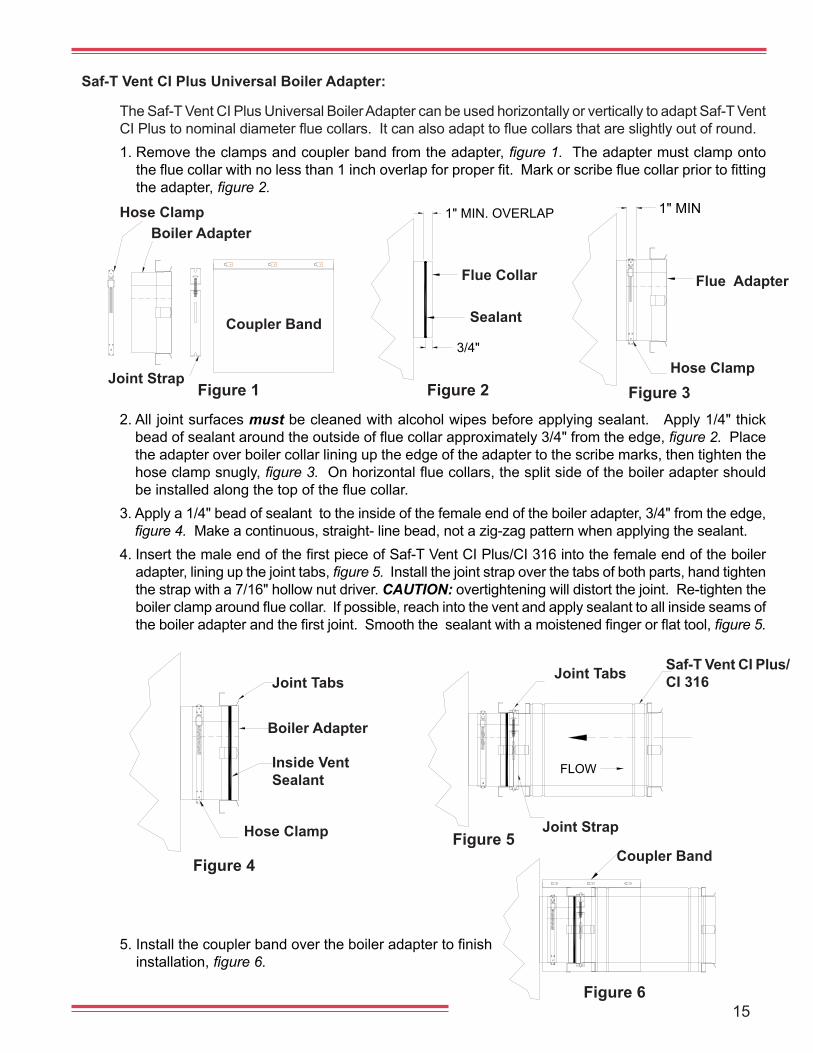
Saf-T Vent CI Plus Universal Boiler Adapter:
The Saf-T Vent CI Plus Universal Boiler Adapter can be used horizontally or vertically to adapt Saf-T Vent CIPlustonominaldiameterfluecollars.Itcanalsoadapttofluecollarsthatareslightlyoutofround.1. Remove the clamps and coupler band from the adapter, figure 1. The adapter must clamp onto thefluecollarwithnolessthan1inchoverlapforproperfit.Markorscribefluecollarpriortofittingthe adapter, figure 2.
2. All joint surfaces must be cleaned with alcohol wipes before applying sealant. Apply 1/4" thick beadofsealantaroundtheoutsideoffluecollarapproximately3/4"fromtheedge,figure 2. Place the adapter over boiler collar lining up the edge of the adapter to the scribe marks, then tighten the hose clamp snugly, figure 3.Onhorizontalfluecollars,thesplitsideoftheboileradaptershouldbeinstalledalongthetopofthefluecollar.
3. Apply a 1/4" bead of sealant to the inside of the female end of the boiler adapter, 3/4" from the edge, figure 4. Make a continuous, straight- line bead, not a zig-zag pattern when applying the sealant.
4.InsertthemaleendofthefirstpieceofSaf-TVentCIPlus/CI316intothefemaleendoftheboileradapter, lining up the joint tabs, figure 5. Install the joint strap over the tabs of both parts, hand tighten the strap with a 7/16" hollow nut driver. CAUTION: overtightening will distort the joint. Re-tighten the boilerclamparoundfluecollar.Ifpossible,reachintotheventandapplysealanttoallinsideseamsoftheboileradapterandthefirstjoint.Smooththesealantwithamoistenedfingerorflattool, figure 5.
1" MIN. OVERLAP
3/4"
Figure 1 Figure 2 Figure 3
Flue Collar Flue Adapter
Hose ClampJoint Strap
Hose ClampBoiler Adapter
Coupler Band
Figure 4Figure 5
Figure 6
Joint Tabs Joint Tabs
Coupler Band
Joint StrapHose Clamp
Saf-T Vent CI Plus/CI 316
Boiler Adapter
Inside Vent Sealant
5.Installthecouplerbandovertheboileradaptertofinishinstallation, figure 6.
Sealant
16
ADJUSTLENGTH
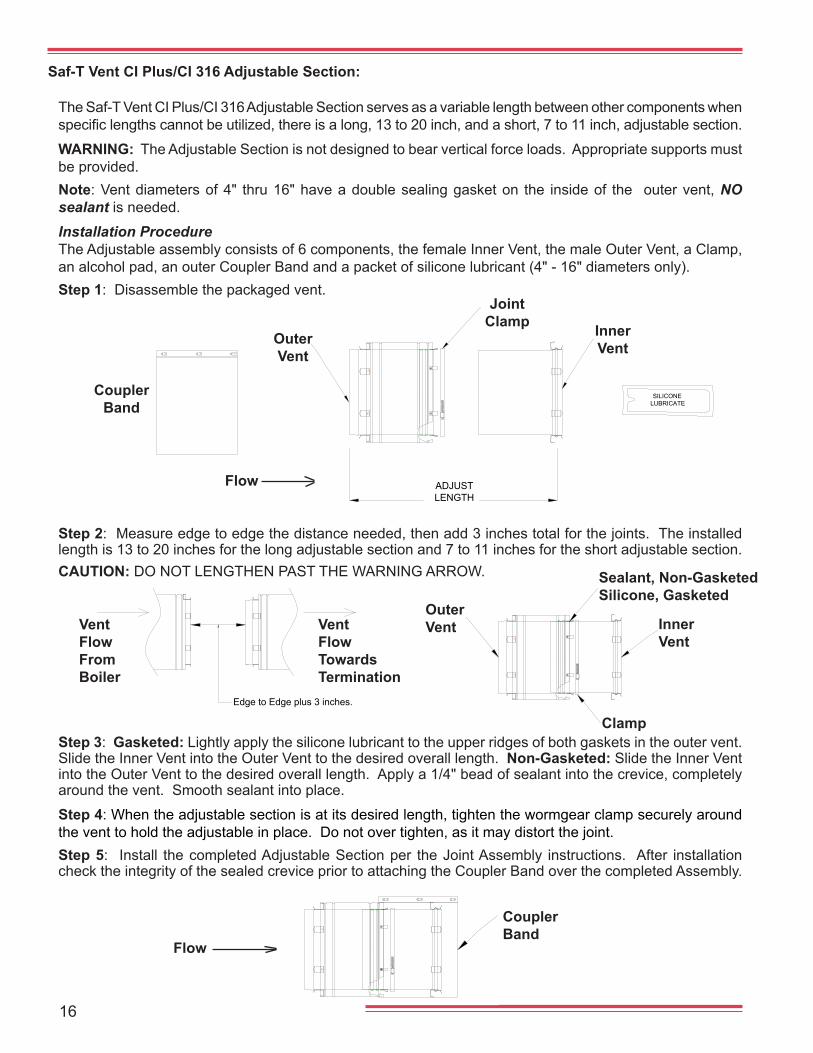
The Saf-T Vent CI Plus/CI 316 Adjustable Section serves as a variable length between other components when specificlengthscannotbeutilized,thereisalong,13to20inch,andashort,7to11inch,adjustablesection.
WARNING: The Adjustable Section is not designed to bear vertical force loads. Appropriate supports must be provided.Note: Vent diameters of 4" thru 16" have a double sealing gasket on the inside of the outer vent, NO sealant is needed.
Installation ProcedureThe Adjustable assembly consists of 6 components, the female Inner Vent, the male Outer Vent, a Clamp, an alcohol pad, an outer Coupler Band and a packet of silicone lubricant (4" - 16" diameters only).Step 1: Disassemble the packaged vent.
Saf-T Vent CI Plus/CI 316 Adjustable Section:
Coupler Band
Outer Vent
Inner Vent
Joint Clamp
Flow
Edge to Edge plus 3 inches.
Vent FlowFrom Boiler
Vent FlowTowards Termination
Step 3: Gasketed: Lightly apply the silicone lubricant to the upper ridges of both gaskets in the outer vent. Slide the Inner Vent into the Outer Vent to the desired overall length. Non-Gasketed: Slide the Inner Vent into the Outer Vent to the desired overall length. Apply a 1/4" bead of sealant into the crevice, completely around the vent. Smooth sealant into place.
Step 4: When the adjustable section is at its desired length, tighten the wormgear clamp securely around the vent to hold the adjustable in place. Do not over tighten, as it may distort the joint.Step 5: Install the completed Adjustable Section per the Joint Assembly instructions. After installation check the integrity of the sealed crevice prior to attaching the Coupler Band over the completed Assembly.
Step 2: Measure edge to edge the distance needed, then add 3 inches total for the joints. The installed length is 13 to 20 inches for the long adjustable section and 7 to 11 inches for the short adjustable section. CAUTION: DO NOT LENGTHEN PAST THE WARNING ARROW.
Outer Vent Inner
Vent
Sealant, Non-GasketedSilicone, Gasketed
Clamp
Coupler Band
Flow
LUBRICATESILICONE
17
Figure 2
HANGERSBY OTHERS
CLAMP
HORIZONTALSUPPORT
CLAMP
HANGERSBY OTHERS
HORIZONTALSUPPORT
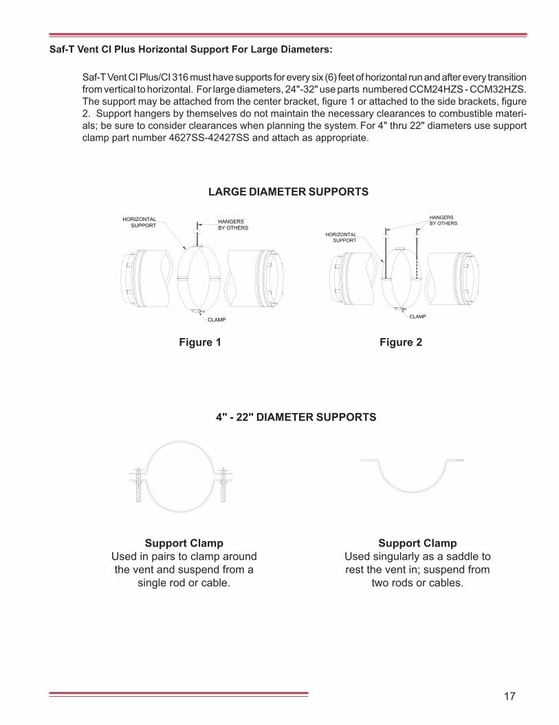
Saf-T Vent CI Plus Horizontal Support For Large Diameters:
Saf-T Vent CI Plus/CI 316 must have supports for every six (6) feet of horizontal run and after every transition from vertical to horizontal. For large diameters, 24"-32" use parts numbered CCM24HZS - CCM32HZS. Thesupportmaybeattachedfromthecenterbracket,figure1orattachedtothesidebrackets,figure2. Support hangers by themselves do not maintain the necessary clearances to combustible materi-als; be sure to consider clearances when planning the system. For 4" thru 22" diameters use support clamp part number 4627SS-42427SS and attach as appropriate.
Figure 1
Support ClampUsed in pairs to clamp aroundthe vent and suspend from a
single rod or cable.
Support ClampUsed singularly as a saddle to rest the vent in; suspend from
two rods or cables.
LARGE DIAMETER SUPPORTS
4" - 22" DIAMETER SUPPORTS
18
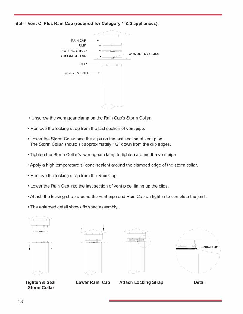
Saf-T Vent CI Plus Rain Cap (required for Category 1 & 2 appliances):
• Unscrew the wormgear clamp on the Rain Cap's Storm Collar.
• Remove the locking strap from the last section of vent pipe.
• Lower the Storm Collar past the clips on the last section of vent pipe. The Storm Collar should sit approximately 1/2” down from the clip edges.
• Tighten the Storm Collar’s wormgear clamp to tighten around the vent pipe.
• Apply a high temperature silicone sealant around the clamped edge of the storm collar.
• Remove the locking strap from the Rain Cap.
• Lower the Rain Cap into the last section of vent pipe, lining up the clips.
• Attach the locking strap around the vent pipe and Rain Cap an tighten to complete the joint.
•Theenlargeddetailshowsfinishedassembly.
CLIP
CLIP
WORMGEAR CLAMP
RAIN CAP
LOCKING STRAPSTORM COLLAR
LAST VENT PIPE
SEALANT
Lower Rain Cap Attach Locking Strap DetailTighten & Seal Storm Collar
19
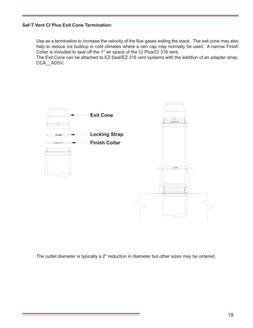
Saf-T Vent CI Plus Exit Cone Termination:
Useasaterminationtoincreasethevelocityofthefluegasesexitingthestack.Theexitconemayalsohelp to reduce ice buildup in cold climates where a rain cap may normally be used. A narrow Finish Collar is included to seal off the 1" air space of the CI Plus/CI 316 vent.The Exit Cone can be attached to EZ Seal/EZ 316 vent systems with the addition of an adapter strap, CCA__ADSV.
The outlet diameter is typically a 2" reduction in diameter but other sizes may be ordered.
Exit Cone
Finish CollarLocking Strap
20
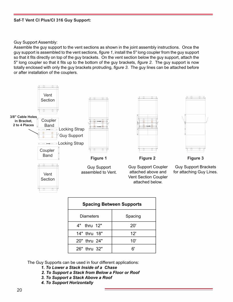
The Guy Supports can be used in four different applications: 1. To Lower a Stack Inside of a Chase 2. To Support a Stack from Below a Floor or Roof 3. To Support a Stack Above a Roof 4. To Support Horizontally
Spacing Between Supports
Diameters Spacing
4" thru 12" 20'
14" thru 18" 12' 20" thru 24" 10'
26" thru 32" 6'
Figure 1 Figure 2 Figure 3
Guy Support assembled to Vent.
Guy Support Coupler attached above and
Vent Section Coupler attached below.
Guy Support Brackets for attaching Guy Lines.
Saf-T Vent CI Plus/CI 316 Guy Support:
Guy Support Assembly:Assemble the guy support to the vent sections as shown in the joint assembly instructions. Once the guy support is assembled to the vent sections, figure 1, install the 5" long coupler from the guy support sothatitfitsdirectlyontopoftheguybrackets.Ontheventsectionbelowtheguysupport,attachthe5"longcouplersothatitfitsuptothebottomoftheguybrackets, figure 2. The guy support is now totally enclosed with only the guy brackets protruding, figure 3. The guy lines can be attached before or after installation of the couplers.
Locking Strap
3/8" Cable Holes in Bracket,
2 to 4 Places
Coupler Band
Vent Section
Vent Section
Coupler Band
Guy SupportLocking Strap
21
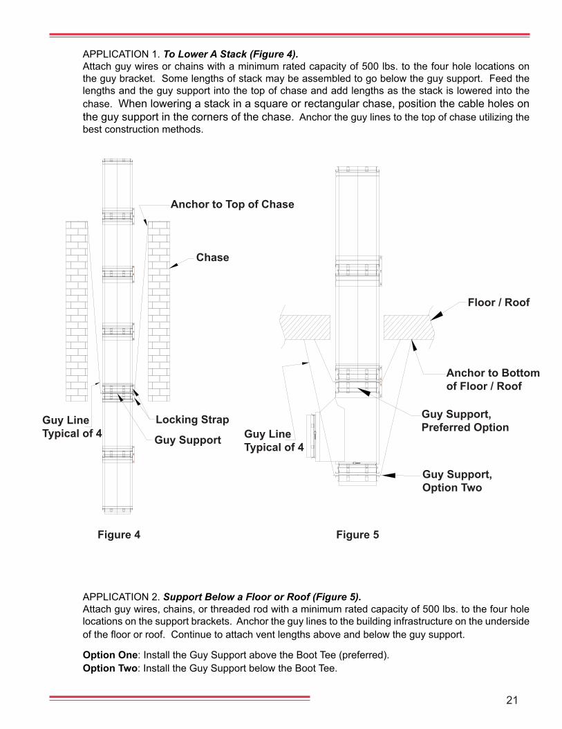
Floor / Roof
Anchor to Bottom of Floor / Roof
Guy Support,Preferred Option
Guy Support, Option Two
Guy Line Typical of 4
APPLICATION 1. To Lower A Stack (Figure 4). Attach guy wires or chains with a minimum rated capacity of 500 lbs. to the four hole locations on the guy bracket. Some lengths of stack may be assembled to go below the guy support. Feed the lengths and the guy support into the top of chase and add lengths as the stack is lowered into the chase. When lowering a stack in a square or rectangular chase, position the cable holes on the guy support in the corners of the chase. Anchor the guy lines to the top of chase utilizing the best construction methods.
APPLICATION 2. Support Below a Floor or Roof (Figure 5). Attach guy wires, chains, or threaded rod with a minimum rated capacity of 500 lbs. to the four hole locations on the support brackets. Anchor the guy lines to the building infrastructure on the underside ofthefloororroof.Continuetoattachventlengthsaboveandbelowtheguysupport.
Option One: Install the Guy Support above the Boot Tee (preferred).Option Two: Install the Guy Support below the Boot Tee.
Guy LineTypical of 4
Anchor to Top of Chase
Chase
Locking Strap
Guy Support
Figure 4 Figure 5
22
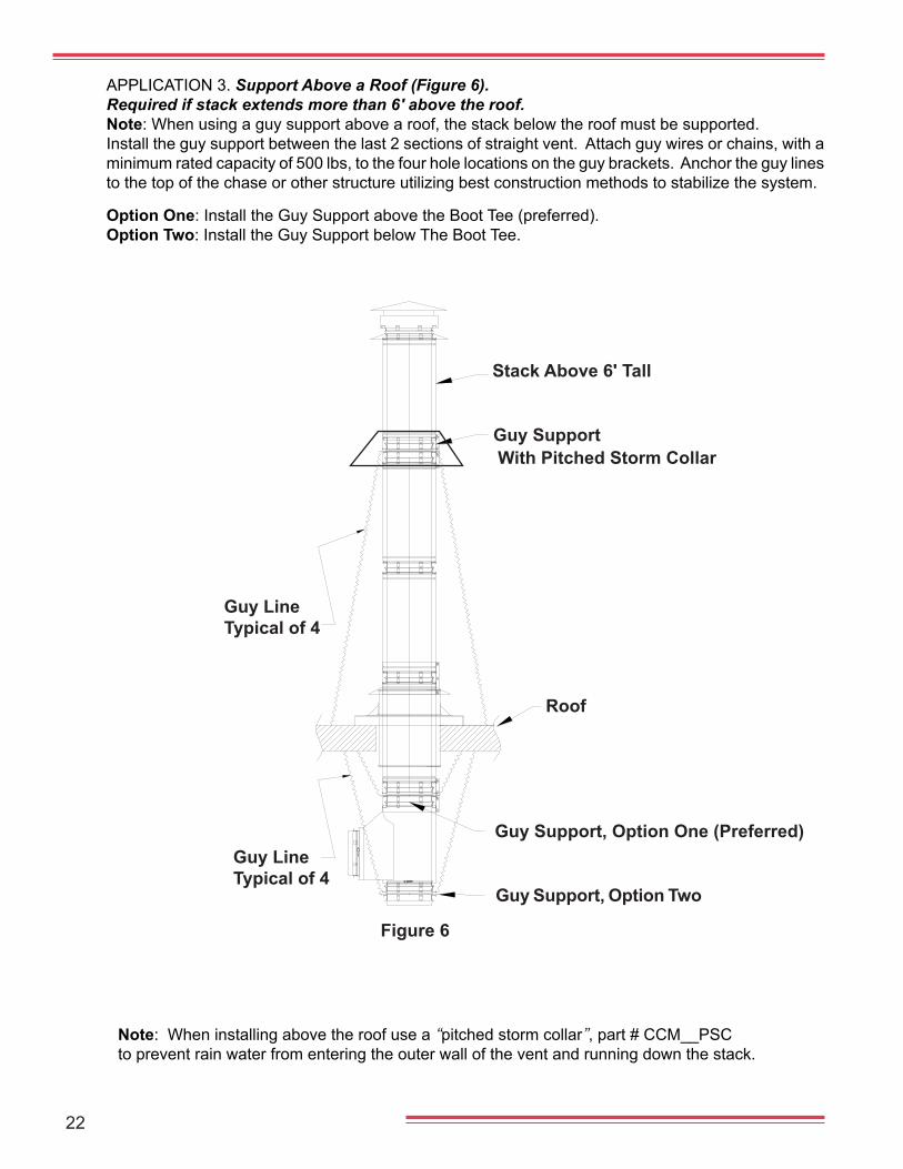
APPLICATION 3. Support Above a Roof (Figure 6). Required if stack extends more than 6' above the roof.Note: When using a guy support above a roof, the stack below the roof must be supported. Install the guy support between the last 2 sections of straight vent. Attach guy wires or chains, with a minimum rated capacity of 500 lbs, to the four hole locations on the guy brackets. Anchor the guy lines to the top of the chase or other structure utilizing best construction methods to stabilize the system.
Option One: Install the Guy Support above the Boot Tee (preferred).Option Two: Install the Guy Support below The Boot Tee.
Figure 6
Guy Support
Guy Support, Option One (Preferred)
Guy Support, Option Two
Guy Line Typical of 4
Stack Above 6' Tall
Guy Line Typical of 4
Roof
With Pitched Storm Collar
Note: When installing above the roof use a “pitched storm collar”, part # CCM__PSCto prevent rain water from entering the outer wall of the vent and running down the stack.
23
5.00
DIM. AALSO ODOF VENT
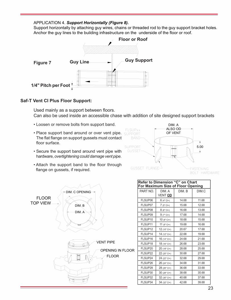
APPLICATION 4. Support Horizontally (Figure 8). Support horizontally by attaching guy wires, chains or threaded rod to the guy support bracket holes. Anchortheguylinestothebuildinginfrastructureontheundersideofthefloororroof.
Figure 7 Guy SupportGuy Line
Floor or Roof
1/4" Pitch per Foot
Usedmainlyasasupportbetweenfloors.Can also be used inside an accessible chase with addition of site designed support brackets
Saf-T Vent CI Plus Floor Support:
• Loosen or remove bolts from support band.
• Place support band around or over vent pipe. Theflatflangeonsupportgussetsmustcontactfloorsurface.
• Secure the support band around vent pipe with hardware, overtightening could damage vent pipe.
•Attach the support band to the floor throughflangeongussets,ifrequired.
DIM. B
DIM. C OPENING
DIM. A
FLOORTOP VIEW
OPENING IN FLOORFLOOR
VENT PIPE
Refer to Dimension “C” on Chart For Maximum Size of Floor OpeningPART NO. DIM. A
VENT ODDIM. B DIM.C
FLSUP06 6 (4" CI+) 14.68 11.68FLSUP07 7 (5" CI+) 15.68 12.68FLSUP08 8 (6" CI+) 16.68 13.68FLSUP09 9 (7" CI+) 17.68 14.68FLSUP10 10 (8" CI+) 18.68 15.68FLSUP11 11 (9" CI+) 19.68 16.68FLSUP12 12 (10" CI+) 20.67 17.68FLSUP14 14 (12" CI+) 22.68 19.68FLSUP16 16 (14" CI+) 24.68 21.68FLSUP18 18 (16" CI+) 26.68 23.68FLSUP20 20 (18" CI+) 28.68 25.68FLSUP22 22 (20" CI+) 30.68 27.68FLSUP24 24 (22" CI+) 32.68 29.68FLSUP26 26 (24" CI+) 34.68 31.68FLSUP28 28 (26" CI+) 36.68 33.68FLSUP30 30 (28" CI+) 38.68 35.68FLSUP32 32 (30" CI+) 40.68 37.68FLSUP34 34 (32" CI+) 42.68 39.68
24
RAIN CAP STORM COLLAR
RAINCAP
COMBUSTIBLECHASE
1" CLEARANCE
APPLY SEALANTABOVE STORM COLLAR
12
ROOF
APPLYSEALANT
2"SPACE
A
NOTE: WHEN USING AS A SUPPORT, THE CONE MUST BE PLACED OVER FRAMING.
BSQUARE
VENTILATIONCOLLAR
SUPPORTSCREWLOCATIONS
2"VENTILATION
SPACE
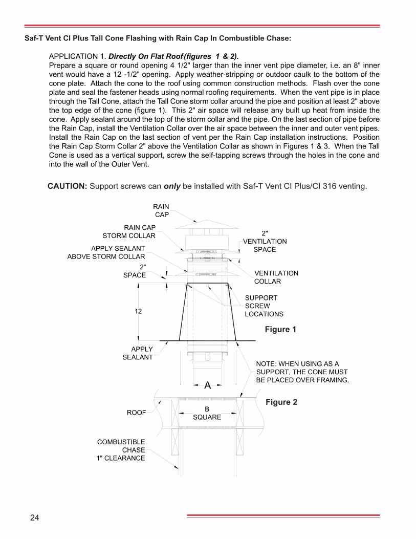
Saf-T Vent CI Plus Tall Cone Flashing with Rain Cap In Combustible Chase:
Figure 2
Figure 1
APPLICATION 1. Directly On Flat Roof (figures 1 & 2).Prepare a square or round opening 4 1/2" larger than the inner vent pipe diameter, i.e. an 8" inner vent would have a 12 -1/2" opening. Apply weather-stripping or outdoor caulk to the bottom of the cone plate. Attach the cone to the roof using common construction methods. Flash over the cone plateandsealthefastenerheadsusingnormalroofingrequirements.Whentheventpipeisinplacethrough the Tall Cone, attach the Tall Cone storm collar around the pipe and position at least 2" above thetopedgeofthecone(figure1).This2"airspacewillreleaseanybuiltupheatfrominsidethecone. Apply sealant around the top of the storm collar and the pipe. On the last section of pipe before the Rain Cap, install the Ventilation Collar over the air space between the inner and outer vent pipes. Install the Rain Cap on the last section of vent per the Rain Cap installation instructions. Position the Rain Cap Storm Collar 2" above the Ventilation Collar as shown in Figures 1 & 3. When the Tall Cone is used as a vertical support, screw the self-tapping screws through the holes in the cone and into the wall of the Outer Vent.
CAUTION: Support screws can only be installed with Saf-T Vent CI Plus/CI 316 venting.
25Figure 3
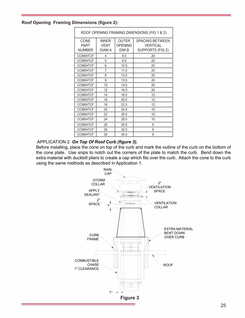
APPLICATION 2. On Top Of Roof Curb (figure 3). Before installing, place the cone on top of the curb and mark the outline of the curb on the bottom of the cone plate. Use snips to notch out the corners of the plate to match the curb. Bend down the extramaterialwithduckbillplierstocreateacapwhichfitsoverthecurb.Attachtheconetothecurbusing the same methods as described in Application 1.
Roof Opening Framing Dimensions (figure 2):
RAINCAP
1"
COMBUSTIBLECHASE
1" CLEARANCE
CURBFRAME
STORMCOLLAR
2"SPACE
APPLYSEALANT
ROOF
VENTILATIONCOLLAR
EXTRA MATERIALBENT DOWNOVER CURB
2"VENTILATION
SPACE
ROOF OPENING FRAMING DIMENSIONS (FIG 1 & 2)
CONE PART
NUMBER
INNER VENT
DIAM A
OUTER OPENING
DIM B
SPACING BETWEEN VERTICAL
SUPPORTS (FIG 2)CCM04TCF 4 8.5 20CCM04TCF 5 9.5 20CCM04TCF 6 10.5 20CCM04TCF 7 11.5 20CCM04TCF 8 12.5 20CCM04TCF 9 13.5 20CCM04TCF 10 14.5 20CCM04TCF 12 16.5 20CCM04TCF 14 18.5 12CCM04TCF 16 20.5 12CCM04TCF 18 22.5 12CCM04TCF 20 24.5 10CCM04TCF 22 26.5 10CCM04TCF 24 28.5 10CCM04TCF 26 30.5 6CCM04TCF 28 32.5 6CCM04TCF 30 34.5 6
26
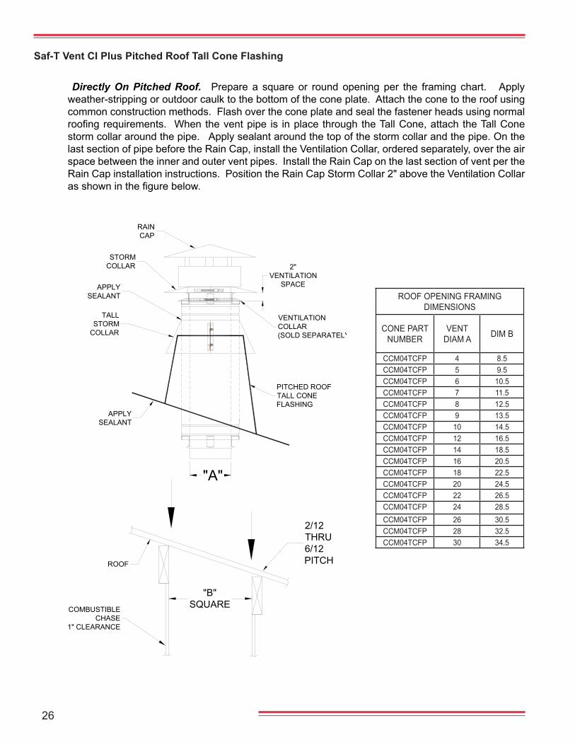
Directly On Pitched Roof. Prepare a square or round opening per the framing chart. Apply weather-stripping or outdoor caulk to the bottom of the cone plate. Attach the cone to the roof using common construction methods. Flash over the cone plate and seal the fastener heads using normal roofingrequirements. Whentheventpipe is inplacethroughtheTallCone,attachtheTallConestorm collar around the pipe. Apply sealant around the top of the storm collar and the pipe. On the last section of pipe before the Rain Cap, install the Ventilation Collar, ordered separately, over the air space between the inner and outer vent pipes. Install the Rain Cap on the last section of vent per the Rain Cap installation instructions. Position the Rain Cap Storm Collar 2" above the Ventilation Collar asshowninthefigurebelow.
Saf-T Vent CI Plus Pitched Roof Tall Cone Flashing
COMBUSTIBLECHASE
1" CLEARANCE
"B"SQUARE
2/12THRU6/12PITCHROOF
"A"
VENTILATIONCOLLAR(SOLD SEPARATELY)
TALLSTORM
COLLAR
APPLYSEALANT
2"VENTILATION
SPACE
STORMCOLLAR
APPLYSEALANT
RAINCAP
PITCHED ROOFTALL CONEFLASHING
ROOF OPENING FRAMING DIMENSIONS
CONE PART NUMBER
VENT DIAM A DIM B
CCM04TCFP 4 8.5CCM04TCFP 5 9.5CCM04TCFP 6 10.5CCM04TCFP 7 11.5CCM04TCFP 8 12.5CCM04TCFP 9 13.5CCM04TCFP 10 14.5CCM04TCFP 12 16.5CCM04TCFP 14 18.5CCM04TCFP 16 20.5CCM04TCFP 18 22.5CCM04TCFP 20 24.5CCM04TCFP 22 26.5CCM04TCFP 24 28.5CCM04TCFP 26 30.5CCM04TCFP 28 32.5CCM04TCFP 30 34.5
27
SILICONESEALANT
COMBUSTIBLE WALL
WEATHERIZING CAULKüüüüüüü
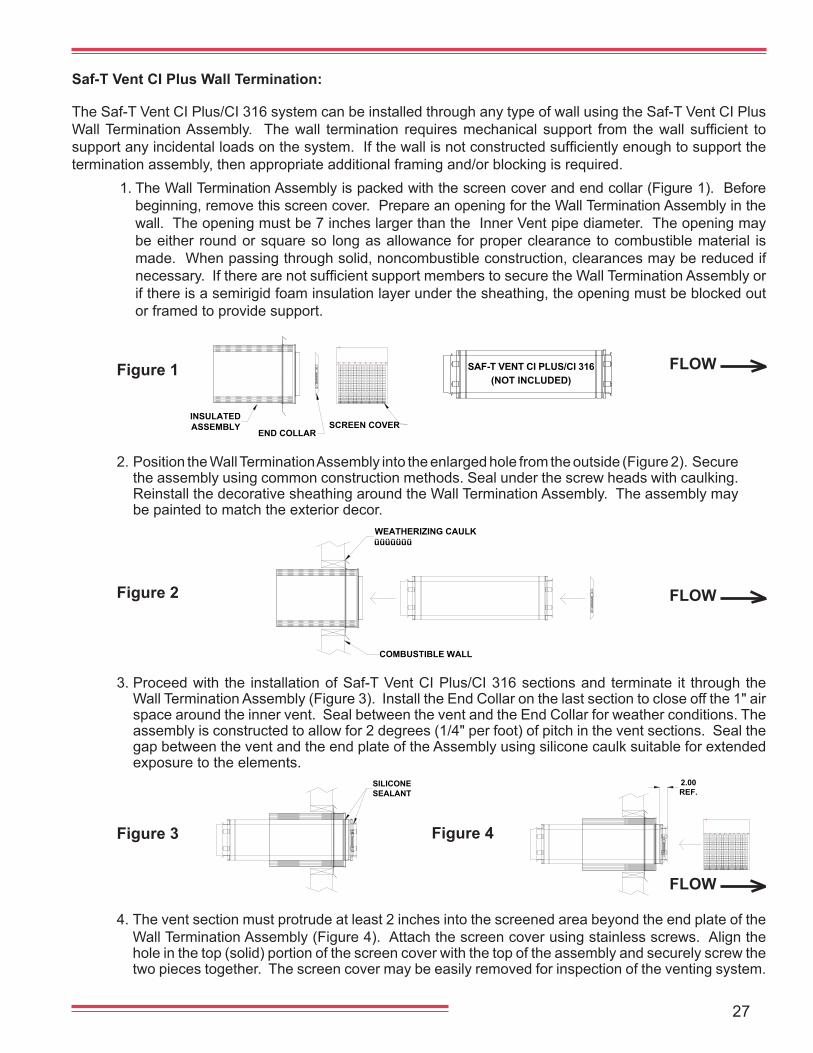
The Saf-T Vent CI Plus/CI 316 system can be installed through any type of wall using the Saf-T Vent CI Plus WallTerminationAssembly. Thewall termination requiresmechanical support from thewall sufficient tosupportanyincidentalloadsonthesystem.Ifthewallisnotconstructedsufficientlyenoughtosupportthetermination assembly, then appropriate additional framing and/or blocking is required.
1. The Wall Termination Assembly is packed with the screen cover and end collar (Figure 1). Before beginning, remove this screen cover. Prepare an opening for the Wall Termination Assembly in the wall. The opening must be 7 inches larger than the Inner Vent pipe diameter. The opening may be either round or square so long as allowance for proper clearance to combustible material is made. When passing through solid, noncombustible construction, clearances may be reduced if necessary.IftherearenotsufficientsupportmemberstosecuretheWallTerminationAssemblyorif there is a semirigid foam insulation layer under the sheathing, the opening must be blocked out or framed to provide support.
Saf-T Vent CI Plus Wall Termination:
Figure 1 FLOW
Figure 2 FLOW
Figure 3
4. The vent section must protrude at least 2 inches into the screened area beyond the end plate of the Wall Termination Assembly (Figure 4). Attach the screen cover using stainless screws. Align the hole in the top (solid) portion of the screen cover with the top of the assembly and securely screw the two pieces together. The screen cover may be easily removed for inspection of the venting system.
2.00REF.
Figure 4
3. Proceed with the installation of Saf-T Vent CI Plus/CI 316 sections and terminate it through the Wall Termination Assembly (Figure 3). Install the End Collar on the last section to close off the 1" air space around the inner vent. Seal between the vent and the End Collar for weather conditions. The assembly is constructed to allow for 2 degrees (1/4" per foot) of pitch in the vent sections. Seal the gap between the vent and the end plate of the Assembly using silicone caulk suitable for extended exposure to the elements.
FLOW
2. Position the Wall Termination Assembly into the enlarged hole from the outside (Figure 2). Secure the assembly using common construction methods. Seal under the screw heads with caulking. Reinstall the decorative sheathing around the Wall Termination Assembly. The assembly may be painted to match the exterior decor.
END COLLAR
INSULATEDASSEMBLY SCREEN COVER
• Normal operation of gas burning appliances does not result in deposits of combustible soot in vent-ing systems. However, a poorly adjusted or malfunctioning appliance can deposit soot and otherdebris which can enter the vent system. As with all vents, the Saf-T Vent CI 316 system should beinspected at least annually for the presence of deposits of soot or debris. Any such accumulationshould be removed and the appliances adjusted to eliminate future accumulation.
• At regular periods the system should also be inspected for signs of leakage of condensate or com-bustion by-products at all joints. If any leakage is found the connected appliances should be turnedoff and the leaks repaired.
• Ifthesystemincorporatesadrainhosefromeitheranin-linefittingorfromadrainteethenthehosemust be inspected periodically to assure that water remains in the trap loop. If a proper trap loopis not maintained exhaust from the connected appliances may accumulate in the building area.
Maintenance Procedures:
2017 Heatfab and Saf-T Vent. All rights reserved.
PI-CCINS 4/17
Combustion & Ventilation Air:In order for appliances and their vent / chimney systems to operate properly they require a plen-
tiful supply of clean combustion and ventilation air. Requirements for such combustion and ventilation air are found in the installation and maintenance instructions accompanying the appliance as well as in vent manufacturer's literature and various mechanical codes. Seek and follow guidelines provided there when installing an appliance / vent system.
In addition to a plentiful source, it is very important for the combustion air to be free of certain chem-ical contaminants that can be very corrosive in nature to the appliance and / or venting system during and as a result of the combustion process.
In some cases, the use of indoor air is acceptable with the exceptions stated below. However, wher-ever possible, it is best to take combustion air directly from the outside, unless outdoor air has contaminant vapors nearby as listed below.
The following common list of substances need to be avoided in all instances since vapors associ-ated with them – if mixed with the combustion air – can be extremely corrosive to the appliance and / or venting system. *Please note this list is not exclusive as to substance or effect and may be supplemented at any time.
a. Permanent wave solutions h. Cleaning solvents (i.e. perchloroethylene)b. Chlorinated waxes and cleaners i. Printing inks, paint removers, varnishes, etc.c. Chlorine based swimming pool chemicals j. Hydrochloric acidd. Water softening chemicals k. Cements and gluese. De-icing salts or chemicals l. Laundry room detergents, fabric softenersf. Carbon tetrachloride m. Masonry acid washing materialsg. Halogen type refrigerants
Corrosion of the vent / chimney caused by the use of contaminated combustion air voids the war-ranty on these products.
Flue gas condensate with PH levels below 2.5 may also void the warranty. PH levels should be monitored regularly and if below 2.5, should be addressed with the boiler OEM on methods to raise it.