Embed Size (px)
Citation preview

NREL is a national laboratory of the U.S. Department of Energy, Office of Energy Efficiency & Renewable Energy, operated by the Alliance for Sustainable Energy, LLC.
Contract No. DE-AC36-08GO28308
SAE J2579 Validation Testing Program Powertech Final Report Mark McDougall Powertech Labs Inc. Surrey, B.C., Canada
Subcontract Report NREL/SR-5600-49867 December, 2010
NREL is a national laboratory of the U.S. Department of Energy, Office of Energy Efficiency & Renewable Energy, operated by the Alliance for Sustainable Energy, LLC.
National Renewable Energy Laboratory 1617 Cole Boulevard Golden, Colorado 80401 303-275-3000 • www.nrel.gov
Contract No. DE-AC36-08GO28308
SAE J2579 Validation Testing Program Powertech Final Report Mark McDougall Powertech Labs Inc. Surrey, B.C., Canada
NREL Technical Monitor: Robert Burgess Prepared under Subcontract No. JFH-7-77618-01
Subcontract Report NREL/SR-5600-49867 December, 2010

This publication was reproduced from the best available copy submitted by the subcontractor and received no editorial review at NREL.
NOTICE
This report was prepared as an account of work sponsored by an agency of the United States government. Neither the United States government nor any agency thereof, nor any of their employees, makes any warranty, express or implied, or assumes any legal liability or responsibility for the accuracy, completeness, or usefulness of any information, apparatus, product, or process disclosed, or represents that its use would not infringe privately owned rights. Reference herein to any specific commercial product, process, or service by trade name, trademark, manufacturer, or otherwise does not necessarily constitute or imply its endorsement, recommendation, or favoring by the United States government or any agency thereof. The views and opinions of authors expressed herein do not necessarily state or reflect those of the United States government or any agency thereof.
Available electronically at http://www.osti.gov/bridge
Available for a processing fee to U.S. Department of Energy and its contractors, in paper, from:
U.S. Department of Energy Office of Scientific and Technical Information
P.O. Box 62 Oak Ridge, TN 37831-0062 phone: 865.576.8401 fax: 865.576.5728 email: mailto:[email protected]
Available for sale to the public, in paper, from:
U.S. Department of Commerce National Technical Information Service 5285 Port Royal Road Springfield, VA 22161 phone: 800.553.6847 fax: 703.605.6900 email: [email protected] online ordering: http://www.ntis.gov/help/ordermethods.aspx
Cover Photos: (left to right) PIX 16416, PIX 17423, PIX 16560, PIX 17613, PIX 17436, PIX 17721
Printed on paper containing at least 50% wastepaper, including 10% post consumer waste.
Page 1
POWERTECH LABS INC.
SAE J2579 Validation Testing Program
Powertech Final Report
Project# 17447-34
May 1, 2009
Prepared for:
Caroline Michaels SAE International
Prepared by:
Mark McDougall, P. Eng.
Project Engineer, Energy Systems Engineering
Reviewed by:
Livio Gambone, P. Eng. Manager, Energy Systems Engineering
SAE International Subcontract JFH-7-77618-01
Technical Monitor: Robert Burgess May 1, 2009 Final Report
Page 2
SUMMARY
SAE International, with funding provided by NREL (National Renewable Energy Laboratory), has contracted Powertech Labs to perform validation testing of the new SAE TIR J2579 document. The program is designed in multiple steps to evaluate different aspects of the document. One major concern with the SAE TIR J2579 document is the time and equipment required to perform the testing. Traditional tank-level test standards (CSA NGV2, CSA Draft HGV2) require approximately 8 weeks to complete a certification program. The sequential nature of the testing, especially in the pneumatic test sequence, of SAE TIR J2579 can lead to dramatically increased test durations. Accordingly, the first goal of the test program was to determine the test duration of the pneumatic sequence. This was accomplished using a Type 4, 70MPa tank. The pneumatic sequence duration was determined to be approximately 13 weeks of continuous testing, based on performing the 500 cycle certification. This amount could be reduced to 10 weeks, depending on the duration of the permeation testing. An additional 3 weeks was “added” to the 10-13 week duration to allow for equipment shut-downs, temperature soaking, and any testing problems which are more prevalent with pneumatic cycling over hydraulic cycling. The resulting increase in test duration is not believed to be overly excessive and can likely be accommodated within the schedule of test laboratories and manufacturers. It was also found that although testing infrastructure upgrades may be required to perform SAE TIR J2579 testing, the equipment required is readily available and can be incorporated into other testing facilities. The second goal of the test program was to ensure that fuel systems (tanks and components) that have had a history of failure under normal vehicle operating conditions would not successfully complete the test sequences specified in SAE TIR J2579. To accomplish this task, a tank with multiple in-service failures was subjected to the test sequences in the document. The Comdyne Type 3 tank (25 MPa service pressure) has had multiple known failures due to cracking of the glass fiber outer wrap. The tank was subjected to the hydraulic test sequence as defined in the document. The first Comdyne tank failed during the final 10 test cycles to 150% of service pressure. This was an unexpected result, as it was believed the tank would fail much sooner in the test sequence. The cause was determined to be an error in the specified test procedure in the draft document, i.e. the 48 hour soak was conducted unpressurized. A second Comdyne tank subjected to the revised test procedure failed 44 hours into the initial 48 hour pressurized soak. The failure mode was determined to be stress corrosion cracking of the glass fibers in the location of the sulfuric acid patch. This confirmed that fuel systems with known in-service failures will not meet the requirements of SAE TIR J2579. The third goal of the test program was to confirm that fuel systems that have not experienced in-service failures will either successfully complete the test sequences specified in SAE TIR J2579, or will fail when the reasons of failure are understood and realistic of future in-service conditions.
Page 3
TABLE OF CONTENTS
SUMMARY .............................................................................................................. 2 TABLE OF CONTENTS ........................................................................................... 3 1.0 BACKGROUND ........................................................................................... 4
1.1 Durability Performance Verification Test .................................................. 4 1.2 Expected-Service Performance Verification Test...................................... 5
2.0 TEST PROGRAM ........................................................................................ 7 2.1 Concept ................................................................................................... 7 2.2 Task Definition in Scope of Work ............................................................. 7
2.2.1 Task 1.0 ........................................................................................... 7 2.2.2 Task 2.0 ........................................................................................... 7 2.2.3 Task 3.0 ........................................................................................... 7 2.2.4 Task 4.0 ........................................................................................... 7 2.2.5 Task 5.0 ........................................................................................... 8 2.2.6 Task 6.0 ........................................................................................... 8 2.2.7 Task 7.0 ........................................................................................... 8 2.2.8 Task 11.0 ......................................................................................... 8
2.3 Test Part 1 ............................................................................................... 8 2.4 Test Part 2 ............................................................................................... 8 2.5 Test Part 3 ............................................................................................... 9
3.0 TEST RESULTS – TEST PART 1 .............................................................. 10 3.1 Time Required for Testing ...................................................................... 10 3.2 Equipment Requirements ....................................................................... 11 3.3 Safety Implications ................................................................................. 12 3.4 Conclusions ........................................................................................... 14
4.0 TEST RESULTS – TEST PART 2 .............................................................. 15 4.1 Hydraulic Test Sequence ....................................................................... 15 4.2 Pneumatic Test Sequence ..................................................................... 16 4.3 Conclusions ........................................................................................... 17
5.0 TEST RESULTS – TEST PART 3 .............................................................. 18 5.1 Hydraulic Test Sequence ....................................................................... 18
5.1.1 70MPa Type 3 Tank ....................................................................... 18 5.1.2 70MPa Type 4 Tank ....................................................................... 19
5.2 Pneumatic Test Sequence ..................................................................... 21 5.2.1 70MPa Type 3 Tank ....................................................................... 21 5.2.2 70MPa Type 4 Tank ....................................................................... 22 5.2.3 70MPa Type 3 System ................................................................... 24 5.2.4 35MPa Type 4 System ................................................................... 25
5.3 Conclusions ........................................................................................... 26 6.0 CONCLUSIONS ......................................................................................... 27
6.1 Test Part 1 ............................................................................................. 27 6.2 Test Part 2 ............................................................................................. 27 6.3 Test Part 3 ............................................................................................. 28

Page 4
1.0 BACKGROUND
The Safety Working Group at the Society of Automotive Engineers (SAE) has developed a new “systems-level” document for hydrogen vehicles. This document, SAE TIR J2579, is a new approach to certification standards for components. The document eliminates the need for dozens of test samples, tested in isolation from each other. SAE TIR J2579 describes the components which create the “high-pressure envelope”, the components whose primary function is the containment of the high-pressure hydrogen on-board the vehicle, and has created a sequential test based on those specific components. The high-pressure envelope is shown in Figure 1.1 below.
Container Vessel
Container
Isolation
Valve
Fill
Check
Valve
Excess
flowReceptacle
with check
Full System
Isolation
Low
Pressure
Regulator
PRVPRV
High
Pressure
Regulator
Hydrogen Fuel Handling System
Compressed Hydrogen
Storage System
PRD
Service
Defuel
Shufoff
vent
Container Vessel
Container
Isolation
Valve
Fill
Check
Valve
Excess
flowReceptacle
with check
Full System
Isolation
Low
Pressure
Regulator
PRVPRV
High
Pressure
Regulator
Hydrogen Fuel Handling System
Compressed Hydrogen
Storage System
PRD
Service
Defuel
Shufoff
vent
Figure 1.1: High-pressure envelope as defined in SAE TIR J2579
The new test procedures have been based on historical tests (from previous standards with a historical pedigree), but with rationale-based modifications. The tests have also been placed into two separate sequences. One sequence is to ensure the fiber-reinforcement is adequate to protect against failure in the worst-case usage scenario. This test sequence is the Durability Performance Verification Test and focuses on external damage and cycle fatigue. The other test sequence is to ensure safe performance of the system under the expected service conditions. This test sequence is the Expected Service Performance Verification Test and focuses on leakage from extreme temperature gas cycle and parking performance (mainly liner tests). The two sequences must both be completed to meet the requirements of SAE TIR J2579.
1.1 Durability Performance Verification Test
Page 5
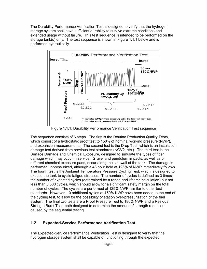
The Durability Performance Verification Test is designed to verify that the hydrogen storage system shall have sufficient durability to survive extreme conditions and extended usage without failure. This test sequence is intended to be performed on the storage tank(s) only. The test sequence is shown in Figure 1.1.1 below and is performed hydraulically.
Figure 1.1.1: Durability Performance Verification Test sequence
The sequence consists of 6 steps. The first is the Routine Production Quality Tests, which consist of a hydrostatic proof test to 150% of nominal working pressure (NWP), and expansion measurements. The second test is the Drop Test, which is an installation damage test derived from previous test standards (NGV2, etc.). The third test is the Surface Damage and Chemical Exposure, designed to simulate the types of fiber damage which may occur in service. Gravel and pendulum impacts, as well as 5 different chemical exposure pads, occur along the sidewall of the tank. The damage is performed unpressurized, although a 48 hour hold at 125% of NWP immediately follows. The fourth test is the Ambient Temperature Pressure Cycling Test, which is designed to expose the tank to cyclic fatigue stresses. The number of cycles is defined as 3 times the number of expected cycles (determined by a range and lifetime calculation) but not less than 5,500 cycles, which should allow for a significant safety margin on the total number of cycles. The cycles are performed at 125% NWP, similar to other test standards. However, 10 additional cycles at 150% NWP have been added to the end of the cycling test, to allow for the possibility of station over-pressurization of the fuel system. The final two tests are a Proof Pressure Test to 180% NWP and a Residual Strength Burst Test, both designed to determine the amount of strength reduction caused by the sequential testing.
1.2 Expected-Service Performance Verification Test
The Expected-Service Performance Verification Test is designed to verify that the hydrogen storage system shall be capable of functioning through the expected
Page 6
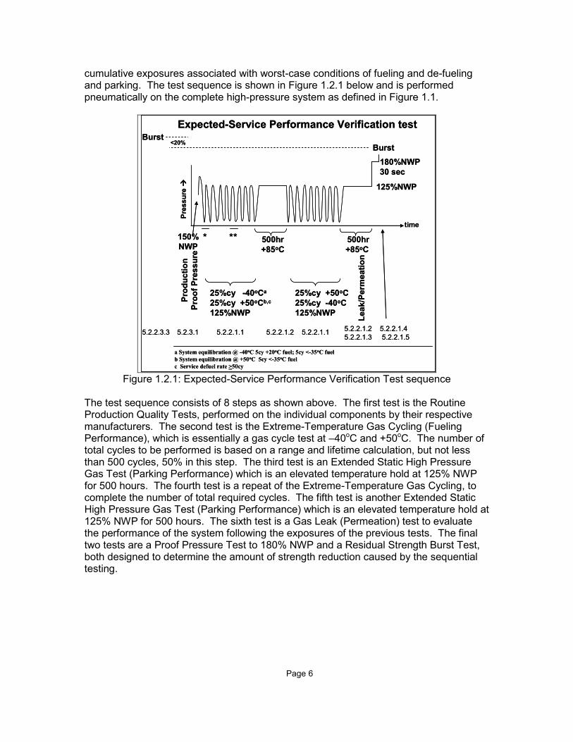
cumulative exposures associated with worst-case conditions of fueling and de-fueling and parking. The test sequence is shown in Figure 1.2.1 below and is performed pneumatically on the complete high-pressure system as defined in Figure 1.1.
Pro
du
cti
on
Pro
of
Pre
ssu
re
25%cy -40oCa
25%cy +50oCb,c
125%NWP
Expected-Service Performance Verification test
180%NWP
30 sec
150%
NWP500hr
+85oC
500hr
+85oC
25%cy +50oC
25%cy -40oC
125%NWP
a System equilibration @ -40oC 5cy +20oC fuel; 5cy <-35oC fuel
b System equilibration @ +50oC 5cy <-35oC fuel
c Service defuel rate >50cy
* **
Pre
ss
ure
Leak/P
erm
eati
on
time
Burst
Burst<20%
5.2.2.1.1 5.2.2.1.25.2.2.1.4
5.2.2.1.55.2.3.1
5.2.2.1.2
5.2.2.1.35.2.2.3.3
125%NWP
5.2.2.1.1
Pro
du
cti
on
Pro
of
Pre
ssu
re
25%cy -40oCa
25%cy +50oCb,c
125%NWP
Expected-Service Performance Verification test
180%NWP
30 sec
150%
NWP500hr
+85oC
500hr
+85oC
25%cy +50oC
25%cy -40oC
125%NWP
a System equilibration @ -40oC 5cy +20oC fuel; 5cy <-35oC fuel
b System equilibration @ +50oC 5cy <-35oC fuel
c Service defuel rate >50cy
* **
Pre
ss
ure
Leak/P
erm
eati
on
time
Burst
Burst<20%
5.2.2.1.1 5.2.2.1.25.2.2.1.4
5.2.2.1.55.2.3.1
5.2.2.1.2
5.2.2.1.35.2.2.3.3
125%NWP
5.2.2.1.1
Figure 1.2.1: Expected-Service Performance Verification Test sequence
The test sequence consists of 8 steps as shown above. The first test is the Routine Production Quality Tests, performed on the individual components by their respective manufacturers. The second test is the Extreme-Temperature Gas Cycling (Fueling Performance), which is essentially a gas cycle test at –40oC and +50oC. The number of total cycles to be performed is based on a range and lifetime calculation, but not less than 500 cycles, 50% in this step. The third test is an Extended Static High Pressure Gas Test (Parking Performance) which is an elevated temperature hold at 125% NWP for 500 hours. The fourth test is a repeat of the Extreme-Temperature Gas Cycling, to complete the number of total required cycles. The fifth test is another Extended Static High Pressure Gas Test (Parking Performance) which is an elevated temperature hold at 125% NWP for 500 hours. The sixth test is a Gas Leak (Permeation) test to evaluate the performance of the system following the exposures of the previous tests. The final two tests are a Proof Pressure Test to 180% NWP and a Residual Strength Burst Test, both designed to determine the amount of strength reduction caused by the sequential testing.
Page 7
2.0 TEST PROGRAM
2.1 Concept
The test program was devised to evaluate the behaviour of different types of hardware when subjected to the new SAE TIR J2579 test sequence. The SAE Working Group identified several aspects of the test sequence that required examination and/or validation prior to the publication of the document. The original scope of work was divided into 7 separate tasks, with an eighth task added later to examine a new concern. However, the original grouping of tasks seemed to fit into 3 examination categories, which is how the data will be presented in this report.
2.2 Task Definition in Scope of Work
The 8 testing tasks defined in the scope of work and contract are described below. These tasks were then re-organized into 3 different test parts, each examining a different area, as opposed to the tasks which examined a specific piece of hardware under a specific test.
2.2.1 Task 1.0
Task 1.0 was to evaluate the time required to conduct the gas pressure cycles in the Expected Service Life Performance Test. This task was performed with a large Type 4 70MPa tank, as this tank size and type was assumed to be worst case for the pneumatic test sequence.
2.2.2 Task 2.0
Task 2.0 was to demonstrate the Expected Service Life Performance Test for typical compressed hydrogen containment systems using a Type 4 polymer-lined carbon-composite fully wrapped containment vessel. This task was performed using a large Type 4 70MPa tank.
2.2.3 Task 3.0
Task 3.0 was to demonstrate the Expected Service Life Performance Test for typical compressed hydrogen containment systems using a Type 3 metal-lined carbon-composite fully wrapped containment vessel. This task was performed using a small Type 3 70MPa tank.
2.2.4 Task 4.0
Task 4.0 was to confirm that types of containers that experienced on-road problems in the past are detected (and rejected) by the proposed tests, using the hydraulic test sequence (Durability Performance Verification Tests). This task was performed using a small Type 3 25MPa glass-fiber reinforced tank, which experienced multiple failures in testing and in service.
Page 8
2.2.5 Task 5.0
Task 5.0 was to confirm that types of containers that experienced on-road problems in the past are detected (and rejected) by the proposed tests, using the pneumatic test sequence (Expected Service Life Performance Verification Tests). This task was modified to test a complete storage system (tank, valve, PRD) through the pneumatic test sequence. The hardware used was a small Type 3 70MPa tank, intank solenoid valve, glass-bulb PRD, and external check valve.
2.2.6 Task 6.0
Task 6.0 was to demonstrate the Durability Performance Verification Test for typical compressed hydrogen containment systems using a Type 3 metal-lined carbon-composite fully wrapped vessel. This task was performed using a small Type 3 70MPa tank.
2.2.7 Task 7.0
Task 6.0 was to demonstrate the Durability Performance Verification Test for typical compressed hydrogen containment systems using a Type 4 polymer-lined carbon-composite fully wrapped vessel. This task was performed using a large Type 4 70MPa tank.
2.2.8 Task 11.0
Task 11.0 was to demonstrate the Expected Service Life Performance Verification Test for typical hydrogen containment system, including the complete high-pressure envelope. This task was performed using a Type 4 35MPa tank with an intank valve (with integral PRD and check valve). The system tested had known performance in on-road service.
2.3 Test Part 1
Test Part 1 was focused on the evaluation of actually performing the test sequences defined in SAE TIR J2579. The hydraulic test sequence (Durability Performance Verification Test) was assumed to be of reasonable short duration and complexity, as the majority of the individual tests were based on previous test standards. The focus of this section was on the time and equipment requirements to perform the pneumatic test sequence (Expected Service Life Performance Verification Test). Also included was an evaluation of the safety implications and requirements for a test lab to safely conduct the pneumatic test sequence. Test Part 1 covered the requirements of Task 1.0, but also covered the general requirements of all other tasks.
2.4 Test Part 2
Test Part 2 was an evaluation of systems that have failed in past vehicle service, to ensure that they would not pass the test sequences in SAE TIR J2579. This test phase was focused on Task 4.0 and the original Task 5.0.
Page 9
2.5 Test Part 3
Test Part 3 was an evaluation of systems that have not failed in past vehicle service. There were two areas of focus in Test Part 3. The first area of focus was on systems that successfully completed the test sequences of SAE TIR J2579. The second area of focus was on systems that failed the test sequences of SAE TIR J2579, but for reasons that are understood and would be expected to occur in future vehicle service. Test Part 3 incorporates the bulk of the testing for this test program. Tasks 2.0, 3.0, 6.0, 7.0 and 11.0 were evaluated as part of Test Part 3.
Page 10
3.0 TEST RESULTS – TEST PART 1
The results of Test Part 1 are separated into the different areas of focus.
3.1 Time Required for Testing
The time required to perform the pneumatic test sequence in SAE TIR J2579 was determined by cycling a large Type 4 70MPa tank. The fueling time was 3 minutes at low temperature and approximately 6 minutes at high temperature. The defueling time for each cycle was approximately 45-60 minutes, varying slightly with each cycle and the temperature effects. This cycling had no lower temperature limit, and used a defuel rate based on 1g/s for each 50L of storage. The test sequence was conducted for 500 cycles. Since the setup and temperature change-over time may vary depending on the test facility, certain assumptions were made using the Powertech Labs facility as the basis. The pneumatic test sequence time was found to be the following:
1. 1 week for the initial 125 pneumatic cycles at +50oC 2. 1 week for the initial 125 pneumatic cycles at -40oC 3. 3 weeks for the first “Parking Performance” extended pressure hold at +85oC 4. 1 week for the remaining 125 pneumatic cycles at -40oC 5. 1 week for the remaining 125 pneumatic cycles at +50oC 6. 3 weeks for the second “Parking Performance” extended pressure hold at +85oC 7. 1 day to 3 weeks for the permeation/leak test (worst case steady-state) 8. 1 day for the hydraulic pressure hold and residual strength burst test.
The total time determined from the testing of the large Type 4 70MPa tank was approximately 10-13 weeks. This test time would be the minimum if the permeation test reaches steady-state quickly (or is at steady-state immediately following the second Parking Performance test). However, the addition of the setup time and the temperature change-over and soaking time will increase total time to 13-16 weeks. The time required to perform the hydraulic test sequence in SAE TIR J2579 was determined to be approximately 1 week. The hydraulic test sequence time was found to be the following:
1. 1 day for the drop tests 2. 4 days for the surface damage and chemical exposure 3. 2 days for the hydraulic pressure cycle test 4. 1 day for the hydraulic pressure hold and residual strength burst test.
Powertech estimates that a traditional tank certification program per ANSI/CSA NGV2 takes a minimum of 8 weeks, and typically 10 weeks. The additional time for performing an SAE TIR J2579 test program is approximately 2-4 weeks. This estimate is based on the cycle times used in the Powertech testing. OEM fuel systems will likely have flow control strategies to limit fuel flow at low temperature, which would increase the cycle time for the –40oC pneumatic cycles. The effects of this increase on total test time is estimated to be 2 weeks.

Page 11
3.2 Equipment Requirements
Powertech Labs has designed and constructed two parallel gas cycle systems capable of performing the SAE TIR J2579 pneumatic test sequence. These two test systems, part of the Hydrogen Gas Cycle Test Facility (shown below), have similar equipment with slightly different capacities. For very high capacity tests, the two systems can be connected to increase the overall capacity of a single test system.
Figure 3.2.1: Powertech Hydrogen Gas Cycle Test Facility
The major equipment required to perform the pneumatic test sequence is:
1. Environmental chamber for the test system 2. Hydrogen gas pre-cooler 3. Hydrogen gas flow control system (inlet and outlet control) 4. Hydrogen compression equipment 5. High-pressure hydrogen storage at 88MPa minimum (for fast fueling) 6. Low-pressure hydrogen storage (to capture defueled hydrogen).
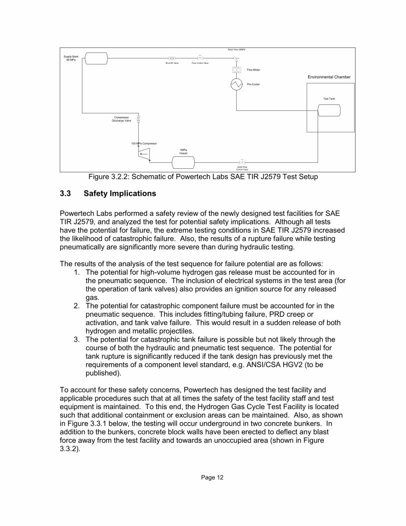
The major pieces of equipment required are all commercially available, with the exception of the hydrogen gas pre-cooler. Powertech uses their proprietary design for the two pre-coolers in the Gas Cycle Test Facility. Below is a schematic of one of the Powertech SAE TIR J2579 test setups.
Page 12
Supply Bank
88 MPa
Test Tank
Shut-Off Valve Flow Control Valve
Relief Valve 90MPa
100 MPa Compressor
Compressor
Discharge Valve
Environmental Chamber
Flow Meter
Pre-Cooler
1MPa
Vessel
Outlet Flow
Control Valve Figure 3.2.2: Schematic of Powertech Labs SAE TIR J2579 Test Setup
3.3 Safety Implications
Powertech Labs performed a safety review of the newly designed test facilities for SAE TIR J2579, and analyzed the test for potential safety implications. Although all tests have the potential for failure, the extreme testing conditions in SAE TIR J2579 increased the likelihood of catastrophic failure. Also, the results of a rupture failure while testing pneumatically are significantly more severe than during hydraulic testing. The results of the analysis of the test sequence for failure potential are as follows:
1. The potential for high-volume hydrogen gas release must be accounted for in the pneumatic sequence. The inclusion of electrical systems in the test area (for the operation of tank valves) also provides an ignition source for any released gas.
2. The potential for catastrophic component failure must be accounted for in the pneumatic sequence. This includes fitting/tubing failure, PRD creep or activation, and tank valve failure. This would result in a sudden release of both hydrogen and metallic projectiles.
3. The potential for catastrophic tank failure is possible but not likely through the course of both the hydraulic and pneumatic test sequence. The potential for tank rupture is significantly reduced if the tank design has previously met the requirements of a component level standard, e.g. ANSI/CSA HGV2 (to be published).
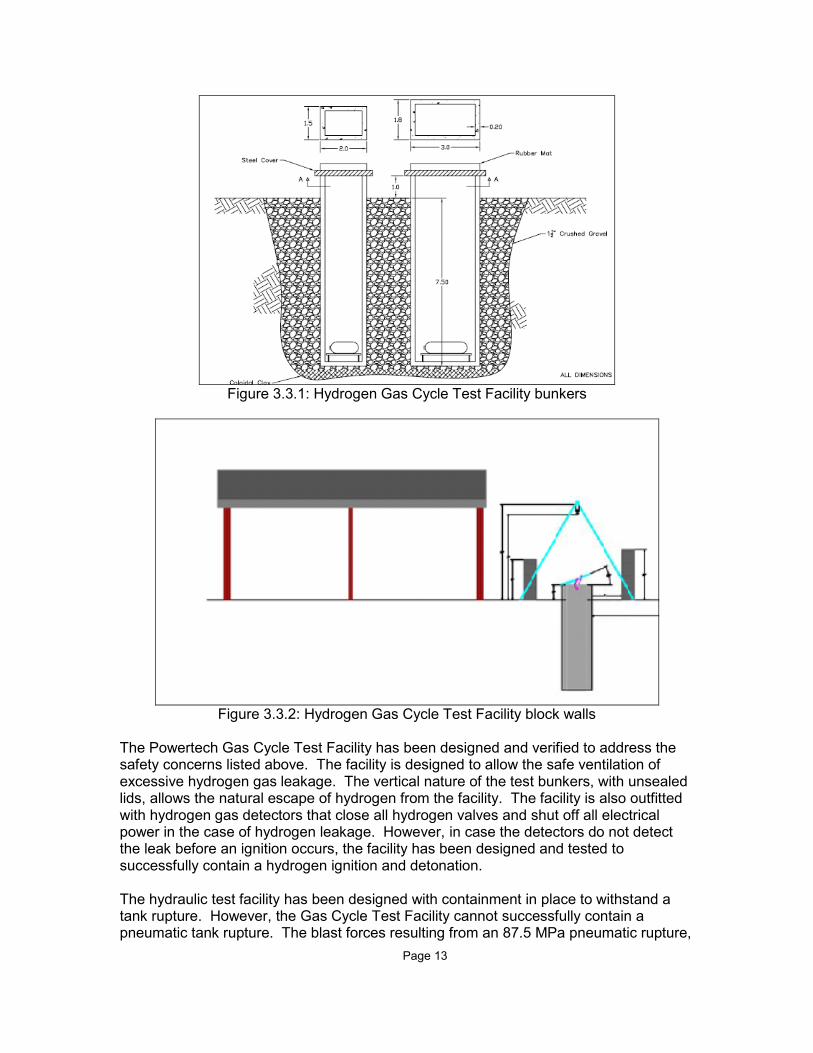
To account for these safety concerns, Powertech has designed the test facility and applicable procedures such that at all times the safety of the test facility staff and test equipment is maintained. To this end, the Hydrogen Gas Cycle Test Facility is located such that additional containment or exclusion areas can be maintained. Also, as shown in Figure 3.3.1 below, the testing will occur underground in two concrete bunkers. In addition to the bunkers, concrete block walls have been erected to deflect any blast force away from the test facility and towards an unoccupied area (shown in Figure 3.3.2).
Page 13
Figure 3.3.1: Hydrogen Gas Cycle Test Facility bunkers
Figure 3.3.2: Hydrogen Gas Cycle Test Facility block walls
The Powertech Gas Cycle Test Facility has been designed and verified to address the safety concerns listed above. The facility is designed to allow the safe ventilation of excessive hydrogen gas leakage. The vertical nature of the test bunkers, with unsealed lids, allows the natural escape of hydrogen from the facility. The facility is also outfitted with hydrogen gas detectors that close all hydrogen valves and shut off all electrical power in the case of hydrogen leakage. However, in case the detectors do not detect the leak before an ignition occurs, the facility has been designed and tested to successfully contain a hydrogen ignition and detonation. The hydraulic test facility has been designed with containment in place to withstand a tank rupture. However, the Gas Cycle Test Facility cannot successfully contain a pneumatic tank rupture. The blast forces resulting from an 87.5 MPa pneumatic rupture,

Page 14
with detonation, are too high to be contained in this type of facility. However, the facility design does limit the damage radius to a manageable distance. To this end, access to the immediate area is restricted during testing. This will result in no personnel being injured in the extremely unlikely event of a pneumatic tank rupture. Powertech has also instituted a further policy that all systems must successfully complete the hydraulic test sequence prior to starting the pneumatic test sequence. Any system that has questionable performance will not be subjected to the pneumatic cycle test.
3.4 Conclusions
Powertech has determined that the tests in SAE TIR J2579 can be performed by any hydrogen test laboratory even though the test procedures are more complicated and time consuming than those specified in traditional tank certification standards. The total test time for the entire standard has increased from 8-10 weeks (for an NGV2 style certification) to approximately 10-13 weeks for SAE TIR J2579. The test equipment, with the exception of the hydrogen gas pre-cooler, is commercially available. A hydrogen-capable test laboratory could design and construct an SAE TIR J2579 test facility. The safety implications are manageable through the application of sound design principles and the implementation of appropriate test procedures. To this end, Powertech has determined that at least three other test laboratories in the world have the expertise required and either are setup, or could be setup, to perform the tests specified in SAE TIR J2579.

Page 15
4.0 TEST RESULTS – TEST PART 2
Test Part 2 was focused on testing fuel systems that have failed in past vehicle service. The purpose is to ensure that fuel systems with known failures do not pass the new test sequences in SAE TIR J2579. A Comdyne 25MPa glass-fiber fully wrapped aluminum-lined tank was selected as the system with known failures in vehicle service. There have been numerous failures of this tank design, in both vehicle service and in routine testing. The failure mode is well documented and understood.
4.1 Hydraulic Test Sequence
The Comdyne tank was subjected to the Durability Performance Verification Test. The tank underwent the drop test, the surface damage and chemical exposure test, and was followed by a 48 hour hold unpressurized. The tank was then subjected to 5,500 hydraulic ambient pressure cycles to 125% of NWP. No tank failure or leakage occurred. The tank was then subjected to 10 hydraulic ambient pressure cycles to 150% of NWP. The tank failed on the fourth cycle at 150% of NWP, shown in Figure 4.1.1 below. The failure occurred much closer to the end of the test than expected from previous testing experience. An error in the test procedure specified in SAE TIR J2579 was found. The original wording did not require the 48 hour hold (during the chemical exposure) to be performed pressurized. However, the intent was for the hold period to be at 125% of NWP. The document was changed, and the test restarted with a second Comdyne tank.
Figure 4.1.1: Comdyne tank #1 failure during hydraulic test sequence
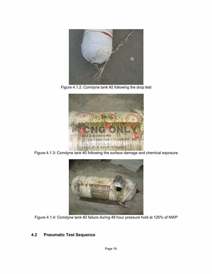
The second Comdyne tank was subjected to the drop test (Figure 4.1.2), the surface damage and chemical exposure (Figure 4.1.3), followed by a 48 hour hold at 125% NWP. The second Comdyne tank failed after 42 hours of pressure hold following chemical exposure. The failure was determined to be stress corrosion cracking of the glass fibers in the location of the sulfuric acid application. A photo of the failure of the second Comdyne tank is shown in Figure 4.1.4.
Page 16
Figure 4.1.2: Comdyne tank #2 following the drop test
Figure 4.1.3: Comdyne tank #2 following the surface damage and chemical exposure
Figure 4.1.4: Comdyne tank #2 failure during 48 hour pressure hold at 125% of NWP
4.2 Pneumatic Test Sequence
Page 17
The Comdyne tank design was not subjected to the Expected Service Life Performance Verification Test since the design failed during the Durability Performance Verification Test. Furthermore, Powertech’s safety procedures would not allow the pneumatic testing of a tank that ruptured during the hydraulic test sequence. The funds allocated to this test were reallocated to perform the Expected Service Life Performance Verification Test on a 70MPa “system”, consisting of a Type 3 tank, an intank solenoid valve with integral PRD, and a check valve. This system contains all the components of the high-pressure envelope described in Figure 1.1. These test results are described in Section 5.
4.3 Conclusions
The test sequences contained in SAE TIR J2579 have been shown to meet the requirement that systems that have failed in past service will not pass the new test sequences. This was shown using the Comdyne 25MPa tank design, which has shown multiple failures in service. Also, an error in the hydraulic test sequence was discovered during the testing, leading to a document revision and a repeat test to confirm the revision.
Page 18
5.0 TEST RESULTS – TEST PART 3
Test Part 3 was the main focus of the testing effort for this program. The pneumatic and hydraulic sequence was performed on both Type 3 and Type 4 70MPa tanks, as well as the pneumatic sequence on a Type 3 70MPa “system” and a Type 4 35MPa “system”. In this testing, there was no lower gas temperature limitation. As mentioned previously, this may not be representative of OEM systems that undergo the test sequences in SAE TIR J2579.
5.1 Hydraulic Test Sequence
The Durability Performance Verification Test was performed on both a small Type 3 70MPa tank and a large Type 4 70MPa tank. The results are summarized below.
5.1.1 70MPa Type 3 Tank
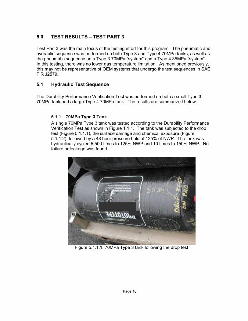
A single 70MPa Type 3 tank was tested according to the Durability Performance Verification Test as shown in Figure 1.1.1. The tank was subjected to the drop test (Figure 5.1.1.1), the surface damage and chemical exposure (Figure 5.1.1.2), followed by a 48 hour pressure hold at 125% of NWP. The tank was hydraulically cycled 5,500 times to 125% NWP and 10 times to 150% NWP. No failure or leakage was found.
Figure 5.1.1.1: 70MPa Type 3 tank following the drop test
Page 19
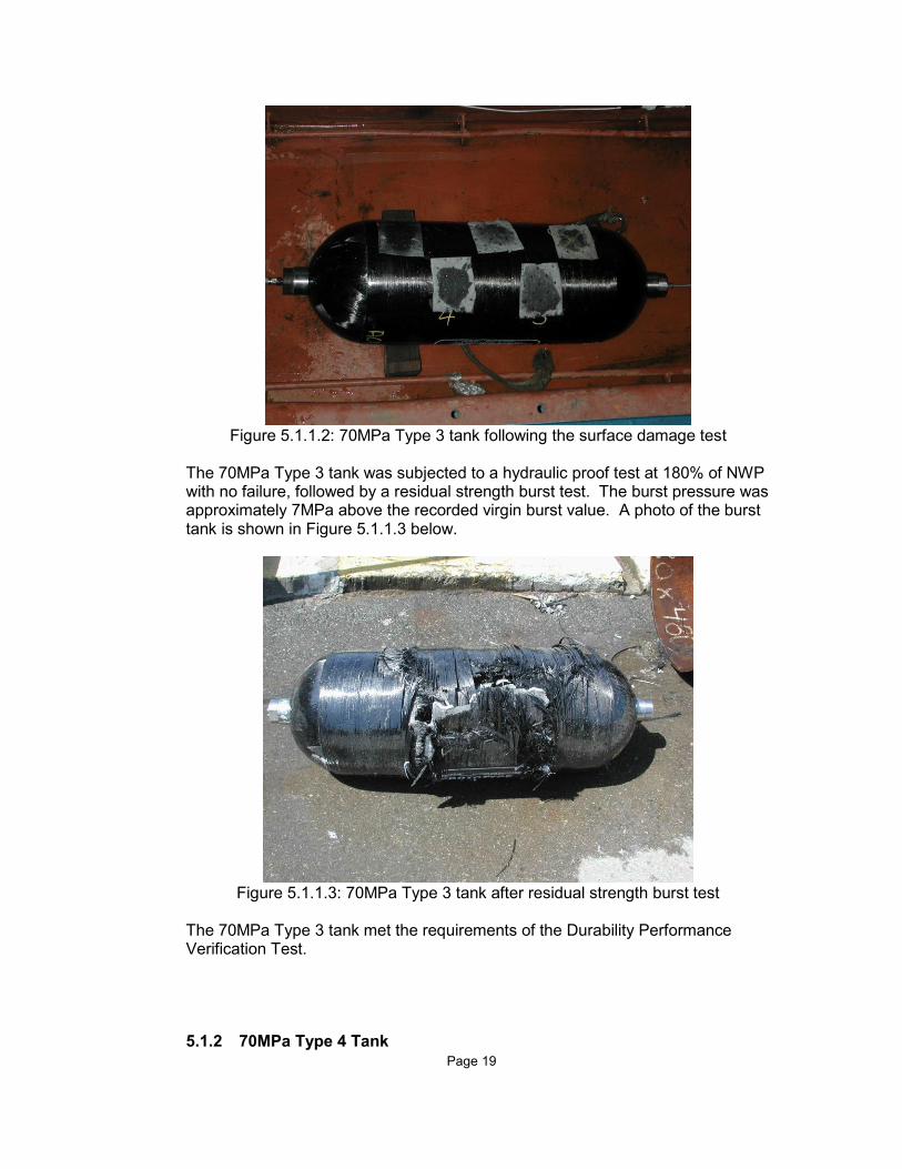
Figure 5.1.1.2: 70MPa Type 3 tank following the surface damage test
The 70MPa Type 3 tank was subjected to a hydraulic proof test at 180% of NWP with no failure, followed by a residual strength burst test. The burst pressure was approximately 7MPa above the recorded virgin burst value. A photo of the burst tank is shown in Figure 5.1.1.3 below.
Figure 5.1.1.3: 70MPa Type 3 tank after residual strength burst test
The 70MPa Type 3 tank met the requirements of the Durability Performance Verification Test.
5.1.2 70MPa Type 4 Tank
Page 20
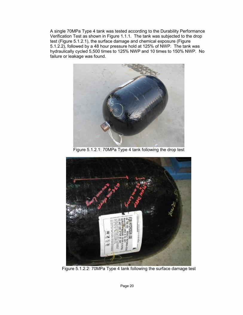
A single 70MPa Type 4 tank was tested according to the Durability Performance Verification Test as shown in Figure 1.1.1. The tank was subjected to the drop test (Figure 5.1.2.1), the surface damage and chemical exposure (Figure 5.1.2.2), followed by a 48 hour pressure hold at 125% of NWP. The tank was hydraulically cycled 5,500 times to 125% NWP and 10 times to 150% NWP. No failure or leakage was found.
Figure 5.1.2.1: 70MPa Type 4 tank following the drop test
Figure 5.1.2.2: 70MPa Type 4 tank following the surface damage test
Page 21
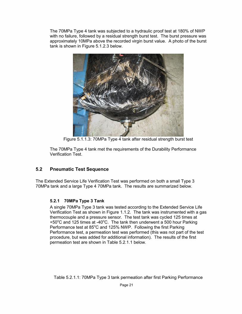
The 70MPa Type 4 tank was subjected to a hydraulic proof test at 180% of NWP with no failure, followed by a residual strength burst test. The burst pressure was approximately 10MPa above the recorded virgin burst value. A photo of the burst tank is shown in Figure 5.1.2.3 below.
Figure 5.1.1.3: 70MPa Type 4 tank after residual strength burst test
The 70MPa Type 4 tank met the requirements of the Durability Performance Verification Test.
5.2 Pneumatic Test Sequence
The Extended Service Life Verification Test was performed on both a small Type 3 70MPa tank and a large Type 4 70MPa tank. The results are summarized below.
5.2.1 70MPa Type 3 Tank
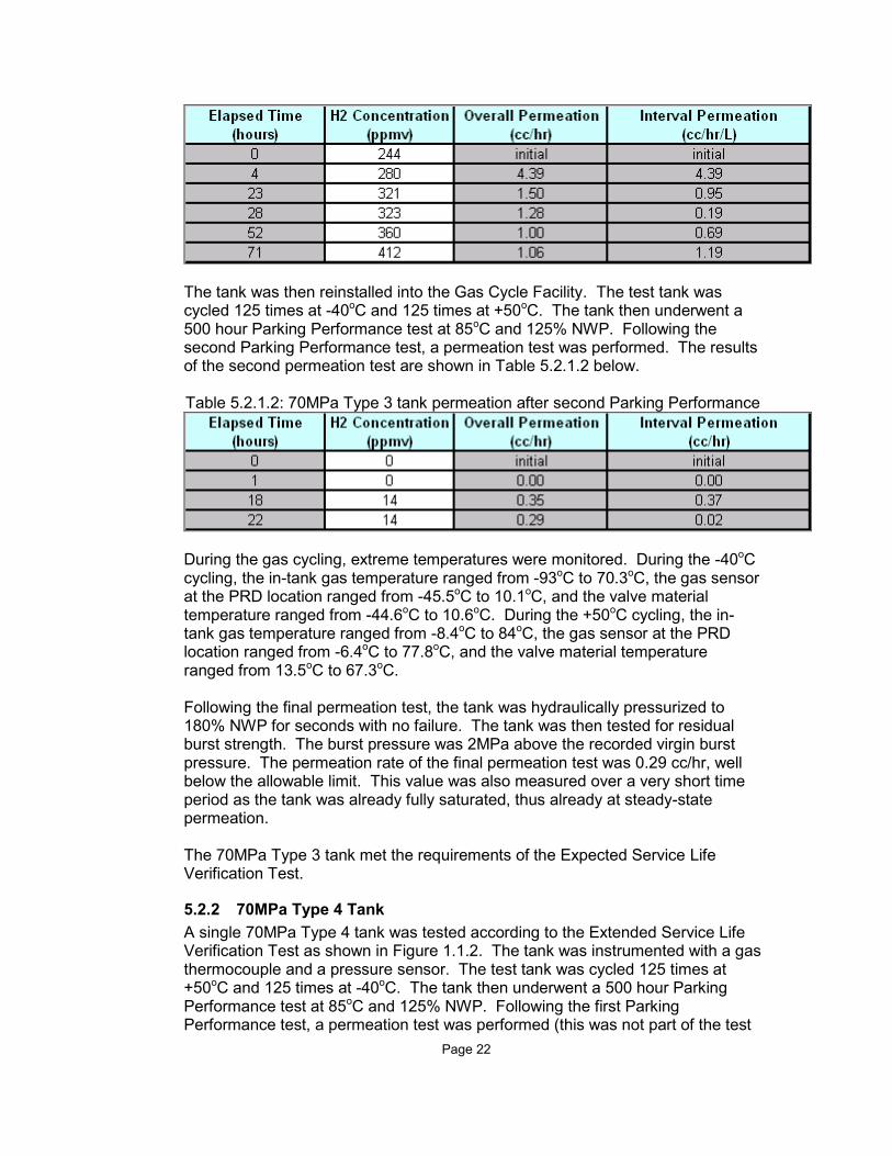
A single 70MPa Type 3 tank was tested according to the Extended Service Life Verification Test as shown in Figure 1.1.2. The tank was instrumented with a gas thermocouple and a pressure sensor. The test tank was cycled 125 times at +50oC and 125 times at -40oC. The tank then underwent a 500 hour Parking Performance test at 85oC and 125% NWP. Following the first Parking Performance test, a permeation test was performed (this was not part of the test procedure, but was added for additional information). The results of the first permeation test are shown in Table 5.2.1.1 below.
Table 5.2.1.1: 70MPa Type 3 tank permeation after first Parking Performance
Page 22
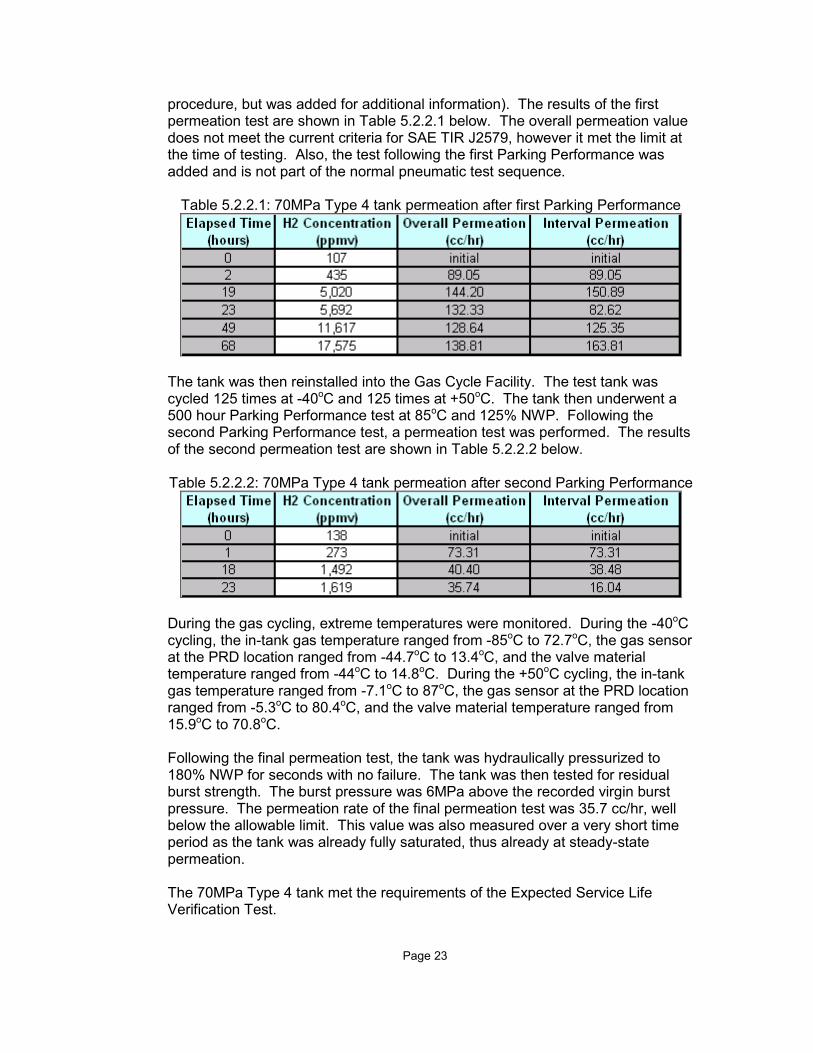
The tank was then reinstalled into the Gas Cycle Facility. The test tank was cycled 125 times at -40oC and 125 times at +50oC. The tank then underwent a 500 hour Parking Performance test at 85oC and 125% NWP. Following the second Parking Performance test, a permeation test was performed. The results of the second permeation test are shown in Table 5.2.1.2 below. Table 5.2.1.2: 70MPa Type 3 tank permeation after second Parking Performance
During the gas cycling, extreme temperatures were monitored. During the -40oC cycling, the in-tank gas temperature ranged from -93oC to 70.3oC, the gas sensor at the PRD location ranged from -45.5oC to 10.1oC, and the valve material temperature ranged from -44.6oC to 10.6oC. During the +50oC cycling, the in-tank gas temperature ranged from -8.4oC to 84oC, the gas sensor at the PRD location ranged from -6.4oC to 77.8oC, and the valve material temperature ranged from 13.5oC to 67.3oC. Following the final permeation test, the tank was hydraulically pressurized to 180% NWP for seconds with no failure. The tank was then tested for residual burst strength. The burst pressure was 2MPa above the recorded virgin burst pressure. The permeation rate of the final permeation test was 0.29 cc/hr, well below the allowable limit. This value was also measured over a very short time period as the tank was already fully saturated, thus already at steady-state permeation. The 70MPa Type 3 tank met the requirements of the Expected Service Life Verification Test.
5.2.2 70MPa Type 4 Tank
A single 70MPa Type 4 tank was tested according to the Extended Service Life Verification Test as shown in Figure 1.1.2. The tank was instrumented with a gas thermocouple and a pressure sensor. The test tank was cycled 125 times at +50oC and 125 times at -40oC. The tank then underwent a 500 hour Parking Performance test at 85oC and 125% NWP. Following the first Parking Performance test, a permeation test was performed (this was not part of the test
Page 23
procedure, but was added for additional information). The results of the first permeation test are shown in Table 5.2.2.1 below. The overall permeation value does not meet the current criteria for SAE TIR J2579, however it met the limit at the time of testing. Also, the test following the first Parking Performance was added and is not part of the normal pneumatic test sequence.
Table 5.2.2.1: 70MPa Type 4 tank permeation after first Parking Performance
The tank was then reinstalled into the Gas Cycle Facility. The test tank was cycled 125 times at -40oC and 125 times at +50oC. The tank then underwent a 500 hour Parking Performance test at 85oC and 125% NWP. Following the second Parking Performance test, a permeation test was performed. The results of the second permeation test are shown in Table 5.2.2.2 below. Table 5.2.2.2: 70MPa Type 4 tank permeation after second Parking Performance
During the gas cycling, extreme temperatures were monitored. During the -40oC cycling, the in-tank gas temperature ranged from -85oC to 72.7oC, the gas sensor at the PRD location ranged from -44.7oC to 13.4oC, and the valve material temperature ranged from -44oC to 14.8oC. During the +50oC cycling, the in-tank gas temperature ranged from -7.1oC to 87oC, the gas sensor at the PRD location ranged from -5.3oC to 80.4oC, and the valve material temperature ranged from 15.9oC to 70.8oC. Following the final permeation test, the tank was hydraulically pressurized to 180% NWP for seconds with no failure. The tank was then tested for residual burst strength. The burst pressure was 6MPa above the recorded virgin burst pressure. The permeation rate of the final permeation test was 35.7 cc/hr, well below the allowable limit. This value was also measured over a very short time period as the tank was already fully saturated, thus already at steady-state permeation. The 70MPa Type 4 tank met the requirements of the Expected Service Life Verification Test.
Page 24
5.2.3 70MPa Type 3 System
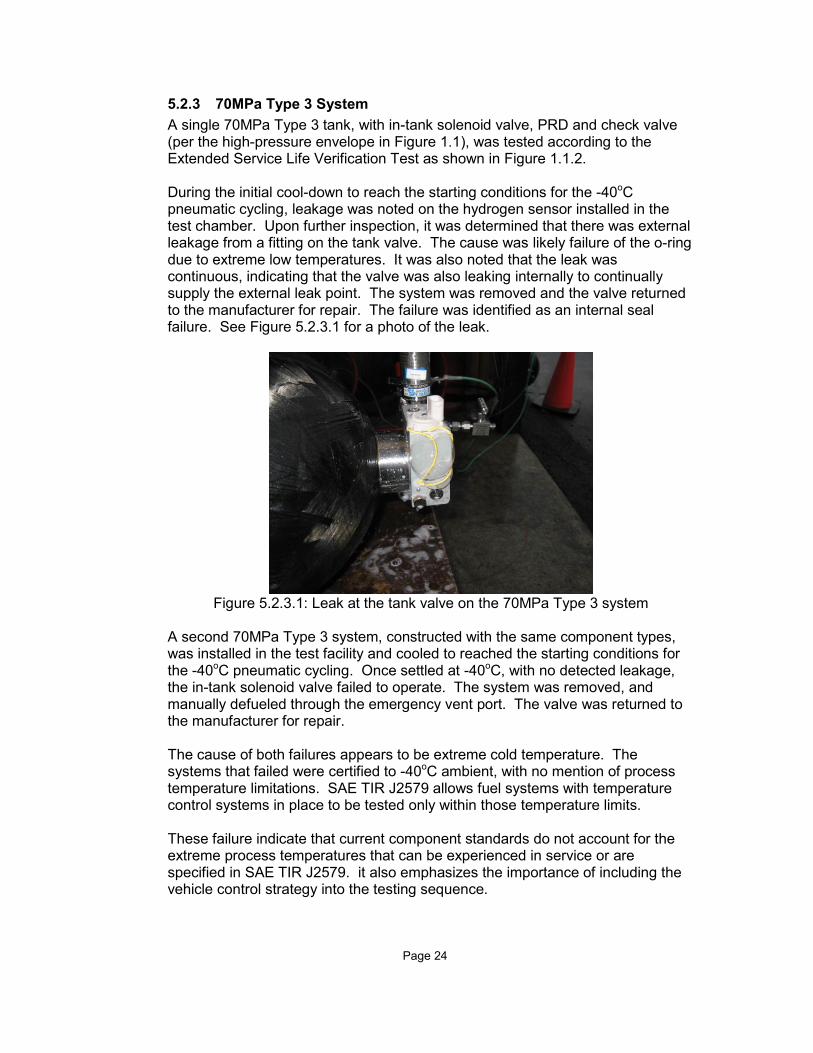
A single 70MPa Type 3 tank, with in-tank solenoid valve, PRD and check valve (per the high-pressure envelope in Figure 1.1), was tested according to the Extended Service Life Verification Test as shown in Figure 1.1.2. During the initial cool-down to reach the starting conditions for the -40oC pneumatic cycling, leakage was noted on the hydrogen sensor installed in the test chamber. Upon further inspection, it was determined that there was external leakage from a fitting on the tank valve. The cause was likely failure of the o-ring due to extreme low temperatures. It was also noted that the leak was continuous, indicating that the valve was also leaking internally to continually supply the external leak point. The system was removed and the valve returned to the manufacturer for repair. The failure was identified as an internal seal failure. See Figure 5.2.3.1 for a photo of the leak.
Figure 5.2.3.1: Leak at the tank valve on the 70MPa Type 3 system
A second 70MPa Type 3 system, constructed with the same component types, was installed in the test facility and cooled to reached the starting conditions for the -40oC pneumatic cycling. Once settled at -40oC, with no detected leakage, the in-tank solenoid valve failed to operate. The system was removed, and manually defueled through the emergency vent port. The valve was returned to the manufacturer for repair. The cause of both failures appears to be extreme cold temperature. The systems that failed were certified to -40oC ambient, with no mention of process temperature limitations. SAE TIR J2579 allows fuel systems with temperature control systems in place to be tested only within those temperature limits. These failure indicate that current component standards do not account for the extreme process temperatures that can be experienced in service or are specified in SAE TIR J2579. it also emphasizes the importance of including the vehicle control strategy into the testing sequence.

Page 25
5.2.4 35MPa Type 4 System
A single 35MPa Type 4 system, with in-tank solenoid valve with integral PRD and check valve, was tested according to the Extended Service Life Verification Test as shown in Figure 1.1.2. The system was cycled 125 times at +50oC and 125 times at -40oC. The tank then underwent a 500 hour Parking Performance test at 85oC and 125% NWP. Following the first Parking Performance test, a permeation test was performed (this was not part of the test procedure, but was added for additional information). The results of the first permeation test are shown in Table 5.2.4.1 below. Table 5.2.4.1: 35MPa Type 4 system permeation after first Parking Performance
The overall permeation rate of the 35MPa Type 4 system was 168 cc/hr, which is above the allowable limit. It was discovered there was a continuous stream of bubbles from a single location on the tank (see Figure 5.2.4.1). The constant stream of bubbles was determined to be of a sufficient rate to sustain a flame, indicating a failure according to the criteria of SAE TIR J2579.
Figure 5.2.4.1: Photo of leak from 35MPa Type 4 system
The failure mode appears to have been caused due to liner damage in the back-end (end furthest from the gas inlet) on the tank. This failure mode has not been experienced in the limited service of this tank, but is realistic of future service. The manufacturer is aware of the failure.

Page 26
5.3 Conclusions
The test sequences of SAE TIR J2579 have been validated against two tanks of known service, although the service was fairly limited. The 70MPa Type 3 tank successfully completed the hydraulic and pneumatic test sequence with no failures, and met the pass criteria established. The 70MPa Type 4 tank successfully completed the hydraulic and pneumatic test sequence with no failures, and met the pass criteria established. Both fuel systems that were tested experienced failures. The 70MPa system failed due to a component limitation at low temperature, which is not unexpected. Current component standards do not address the full range of process temperatures that can be experienced in service. This is accounted for in the test document by allowing fuel systems with internal controls to limit flow and/or operating temperature during testing. The 35MPa system failed due to a tank leak likely caused by high temperature pneumatic cycling. This failure mode has not been seen in the limited service life of the tank design, but is realistic of future service conditions. The test sequences in SAE TIR J2579 have shown that tanks with no known failures in service either met the requirements of the tests, or fail for reasons that are understood and are representative of future service conditions.
Page 27
6.0 CONCLUSIONS
Powertech has completed the test program for SAE International, funded by the US DOE through NREL. Although the original program was divided into 8 testing tasks, the data has been presented in 3 parts, to allow for a clearer presentation of information.
6.1 Test Part 1
The goal of Test Part 1 was to examine the facility and time requirements to perform the test sequences of SAE TIR J2579, especially the pneumatic sequence. It was found that the pneumatic sequence can be performed in 10 weeks, with some reductions based on the time to steady-state permeation of the test tanks. However, it was noted that if setup time and temperature change-over time is included in the test time, the total time increases to approximately 13 weeks. Powertech Labs has constructed two parallel SAE TIR J2579 test setups, within the Gas Cycle Test Facility. These setups were constructed using commercially available components, with the exception of the hydrogen gas pre-coolers. An in-depth safety analysis of the test sequences and facility was performed as well. The conclusions of that analysis are that any potential safety issues can be mitigated through facility design and laboratory test procedures. Powertech has designed and validated its facilities to be able to safely perform the testing specified in SAE TIR J2579. It was also determined that any hydrogen-capable test laboratory could be setup to perform the pneumatic test sequence. At the time of the project, Powertech was aware of three other test facilities that are already setup, or could be quickly setup, to perform the pneumatic test sequence specified in SAE TIR J2579.
6.2 Test Part 2
The goal of Test Part 2 was to demonstrate that fuel systems that have known failures in service do not pass the test sequences of SAE TIR J2579. To demonstrate this, Powertech tested a Comdyne 25MPa tank design. The Comdyne design has experienced multiple failures in service. The Comdyne tank was first tested to the hydraulic test sequence. The first Comdyne tank failed after 4 cycles at 150% NWP, near the end of the test sequence. The result was unexpected, and led to the discovery of an error in SAE TIR J2579. The document was revised, and a second Comdyne tank was tested to the modified hydraulic sequence. The second Comdyne failed following 42 hours of pressure hold at 125% NWP. The planned testing of the Comdyne tank to the pneumatic test sequence was revised, as the Comdyne had already failed SAE TIR J2579 and Powertech test procedures would not allow the pneumatic testing of a tank that had previously failed the hydraulic

Page 28
test. The funds allocated to this task were re-allocated to allow for the pneumatic testing of a 70MPa Type 3 system. It was demonstrated that fuel systems with known service failures do not pass the test sequences specified in SAE TIR J2579.
6.3 Test Part 3
The goal of Test Part 3 was to demonstrate that fuel systems with no history of service failures either pass the test sequences of SAE TIR J2579, or fail when the reasons are understood and representative of future service conditions. To demonstrate this, a 70MPa Type 3 tank design and a 70MPa Type 4 tank design were tested to both the hydraulic and pneumatic test sequences. Additionally, a 70MPa Type 3 system and a 35MPa Type 4 system were tested to the pneumatic test sequence. The 70MPa Type 3 tank met the requirements of the hydraulic test sequence, resulting in a residual burst strength 7MPa higher than the recorded virgin burst pressure. The 70MPa Type 3 tank met the requirements of the pneumatic test sequence, resulting in a residual burst strength 2MPa higher than the recorded virgin burst pressure and an overall permeation rate of 0.29 cc/hr. The 70MPa Type 4 tank met the requirements of the hydraulic test sequence, resulting in a residual burst strength 10MPa higher than the recorded virgin burst pressure. The 70MPa Type 4 tank met the requirements of the pneumatic test sequence, resulting in a residual burst strength 7MPa higher than the recorded virgin burst pressure and an overall permeation rate of 35.7 cc/hr. The 70MPa Type 3 system failed during the -40oC pneumatic cycling due to in-tank valve problems. The failure indicates that both the component level standards are inadequate for the extreme service conditions expected in future service, and that current hardware has service limitations. It is noted that the pneumatic test sequence in SAE TIR J2579 has an allowance for the testing of hardware with service limitations. The 35MPa Type 4 system failed following the first 250 pneumatic cycles. The failure was noted as a high permeation value of 168 cc/hr, which was confirmed as a constant leak of hydrogen from a single location on the tank. The failure was likely liner damage caused by high-temperature pneumatic cycling. The failure has not been experienced in the limited service of this tank design, but is realistic of future service conditions. It was demonstrated that fuel systems with no history of failure in service either pass the test sequences of SAE TIR J2579 (the 70MPa Type 3 tank and the 70MPa Type 4 tank), or fail for reasons that are understood and are expected in future service (the 70MPa Type 3 system and the 35MPa Type 4 system).
F1146-E(10/2008)
REPORT DOCUMENTATION PAGE Form Approved OMB No. 0704-0188
The public reporting burden for this collection of information is estimated to average 1 hour per response, including the time for reviewing instructions, searching existing data sources, gathering and maintaining the data needed, and completing and reviewing the collection of information. Send comments regarding this burden estimate or any other aspect of this collection of information, including suggestions for reducing the burden, to Department of Defense, Executive Services and Communications Directorate (0704-0188). Respondents should be aware that notwithstanding any other provision of law, no person shall be subject to any penalty for failing to comply with a collection of information if it does not display a currently valid OMB control number. PLEASE DO NOT RETURN YOUR FORM TO THE ABOVE ORGANIZATION. 1. REPORT DATE (DD-MM-YYYY)
December 2010 2. REPORT TYPE
Subcontract Report 3. DATES COVERED (From - To)
1 May 2009 - 31 August 2009 4. TITLE AND SUBTITLE
SAE J2579 Validation Testing Program: Powertech Final Report, 1 May 2009 -- 31 August 2009
5a. CONTRACT NUMBER DE-AC36-08-GO28308
5b. GRANT NUMBER
5c. PROGRAM ELEMENT NUMBER
6. AUTHOR(S) Mark McDougall
5d. PROJECT NUMBER NREL/SR-5600-49867
5e. TASK NUMBER H2747210
5f. WORK UNIT NUMBER
7. PERFORMING ORGANIZATION NAME(S) AND ADDRESS(ES) SAE International 755 W. Big Beaver Troy, MI 48084
8. PERFORMING ORGANIZATION REPORT NUMBER JFH-7-77618-01
9. SPONSORING/MONITORING AGENCY NAME(S) AND ADDRESS(ES) National Renewable Energy Laboratory 1617 Cole Blvd. Golden, CO 80401-3393
10. SPONSOR/MONITOR'S ACRONYM(S) NREL
11. SPONSORING/MONITORING AGENCY REPORT NUMBER NREL/SR-5600-49867
12. DISTRIBUTION AVAILABILITY STATEMENT National Technical Information Service U.S. Department of Commerce 5285 Port Royal Road Springfield, VA 22161
13. SUPPLEMENTARY NOTES NREL Technical Monitor: R. Burgess
14. ABSTRACT (Maximum 200 Words) The Safety Working Group at the Society of Automotive Engineers (SAE) has developed a new “systems-level” document for hydrogen vehicles. This document, SAE TIR J2579, is a new approach to certification standards for components. The document eliminates the need for dozens of test samples, tested in isolation from each other. SAE TIR J2579 describes the components which create the “high-pressure envelope”, the components whose primary function is the containment of the high-pressure hydrogen on-board the vehicle, and has created a sequential test based on those specific components.
15. SUBJECT TERMS tank-level test standards; vehicle fuel-system tests; hydrogen fuel handling system
16. SECURITY CLASSIFICATION OF: 17. LIMITATION OF ABSTRACT
UL
18. NUMBER OF PAGES
19a. NAME OF RESPONSIBLE PERSON a. REPORT
Unclassified b. ABSTRACT Unclassified
c. THIS PAGE Unclassified 19b. TELEPHONE NUMBER (Include area code)
Standard Form 298 (Rev. 8/98) Prescribed by ANSI Std. Z39.18