Embed Size (px)
DESCRIPTION
Software Architecture Analysis Method
Citation preview
SAAM: A Method for Analyzing the Properties of Software Architectures
Abstract
While software architecture has become an increasinglyimportant research topic in recent years, insufficient atten-tion has been paid to methods for evaluation of these archi-tectures. Evaluating architectures is difficult for two mainreasons. First, there is no common language used to de-scribe different architectures. Second, there is no clear wayof understanding an architecture with respect to an organi-zation’s life cycle concerns—software quality concernssuch as maintainability, portability, modularity, reusability,and so forth. This paper addresses these shortcomings bydescribing three perspectives by which we can understandthe description of a software architecture and then propos-ing a five-step method for analyzing software architecturescalled SAAM (Software Architecture Analysis Method). Weillustrate the method by analyzing three separate user in-terface architectures with respect to the quality of modifi-ability.
1 Introduction
Software architecture is a topic of growing concernwithin both the academic and industrial communities.Despite the popularity of this topic, little attention focuseson methods for analyzing a software architecture to showthat it satisfies certain properties. Software architecturesare primarily motivated by software engineering consider-ations, or software quality factors, such as maintainability,portability, modularity and reusability. In this paper, weaddress architectural description and a method of analysiswith respect to software quality. The method is demon-strated by means of a case study examining architecturesfor developing the user interface portion of interactive sys-tems.
Over the past decade, changes in the software architec-ture characterize the advances in support environments forthe development of user interfaces. However, it is oftendifficult to assess a developer's claims of qualities inherent
in a software architecture. Examples of such claims are:
We have developed … user interface componentsthat can be reconfigured with minimal effort. [20]
Serpent … encourages the separation of softwaresystems into user interface and “core” applicationportions, a separation which will decrease the costof subsequent modifications to the system. [22]
This Nephew UIMS/Application interface is bet-ter that [sic] traditional UIMS/Application inter-faces from the modularity and code reusabilitypoint of views. [26]
The difficulty in assessing the validity of these claimsarises for two reasons. First, the various architecturaldescriptions do not use a common vocabulary. When peo-ple develop new architectures, they typically develop newterms to describe them, or use old terms in a new way. Itis, therefore, difficult to compare these new architectureswith existing ones—there is no level playing field. Second,it is often difficult to link architectural abstractions withsystem development concerns. Developers tend to concen-trate on the functional features of their architectures, andseldom address the ways in which their architectures sup-port quality concerns within the system development lifecycle.
The main goal of this paper, therefore, is to establish amethod for describing and analyzing software architec-tures, called the Software Architecture Analysis Method(SAAM). Before analyzing an architecture, we must firsthave a way to provide a clear description of it whichexposes its main features. We define three perspectives forunderstanding and describing architectures—functionality,structure and allocation. We also provide a simple lan-guage for describing the structural perspective. This lan-guage is important because i t permits differentarchitectures to be described consistently, forcing a com-mon level of understanding for comparing different archi-tectures.
Rick Kazman
Department of Computer ScienceUniversity of Waterloo
Waterloo, ON Canada N2L [email protected]
Len Bass, Gregory Abowd
Software Engineering InstituteCarnegie Mellon University
Pittsburgh, PA, U.S.A. 15213{ljb,gda}@sei.cmu.edu
Mike Webb
Texas Instruments Inc.Dallas, TX, U.S.A. 75265
{smw}@sei.cmu.edu
After we have a way to describe an architecture, we canapply the SAAM to analyze it. The main activitiesinvolved in the SAAM are enumerated below.
1. Characterize a canonical functional partition-ing for the domain.
2. Map the functional partitioning onto the ar-chitecture’s structural decomposition.
3. Choose a set of quality attributes with whichto assess the architecture.
4. Choose a set of concrete tasks which test thedesired quality attributes.
5. Evaluate the degree to which each architec-ture provides support for each task.
It is a secondary goal of this paper is to demonstrate theutility of this general architectural analysis method for theevaluation of user interface architectures.
1.1 Background
Our approach to the analysis of software at the architec-tural level reflects a growing trend in software engineer-ing. That trend emphasizes a better understanding ofgeneral architectural concepts as a foundation for theproof that a system meets more than just functionalrequirements [12]. We agree with Perry and Wolf [18] thatan architectural description provides multiple perspectivesof different information, though their perspectives wouldrightly be considered as perspectives on structure in ourterms. They also promote the use of a small lexicon of ele-ments to portray structure as do Abowd, Allen and Garlan[2] and Garlan and Shaw [8]. Our small lexicon, however,resulted more because it was sufficient for the task at handand not out of any conviction that a small vocabulary wasessential.
We are not original in our desire to predict the qualityof a software product from a higher level design descrip-tion. For example, Parnas [17] motivated the use of modu-larization or information hiding as a means of high-levelsystem decomposition to improve flexibility and compre-hensibility. Stevens, Myers and Constantine [25] intro-duced the notions of module coupling and cohesion toevaluate alternatives for program decomposition. The soft-ware metrics community has used these notions to definepredictive measures of software quality (see, for example,the work by Briand, Morasca and Basili [6]). Our analysismethod appeals to a more abstract evaluation of how thearchitecture fulfills the domain functionality and othernonfunctional qualities. We do not present any metrics forpredictive evaluation, but instead present an example-based method for performing a more qualitative evalua-tion.
Garlan and Shaw demonstrated how the examination of
significant architectural case studies can help to define thefield of software architecture, and this is why we chose toground our general analysis method in a concrete domain.Although we have extensive experience in the field ofHuman-Computer Interaction and user interface develop-ment and analysis, our main interest in writing this paperwas not so much for the HCI community but for the gen-eral software engineering community interested in under-standing how clear and coherent software architecturescan aid in analysis. Having said that, there is a clear contri-bution in our work for the user interface developmentcommunity. There is an abundance of literature whichtakes a taxonomic approach to classifying the many userinterface development tools ([4], [11]). Rather than simplyclassify various user interface development tools, we pro-vide a means of evaluating their suitability for producingmodifiable interactive systems.
1.2 Overview
In Section 2, we define the three distinct perspectives,functionality, structure and allocation, used to describe asoftware architecture and we introduce the simple lexiconfor the structural perspective. The remainder of the paperdemonstrates the application of the SAAM to the casestudy of user interface software. In Section 3, we define acanonical functional partitioning for user interface soft-ware and examine how that functionality is allocated forthree distinct user interface development environments. InSection 4, we discuss one quality attribute, modifiability,important for user interface software. We then identify twobenchmark modification tasks which are used in Section 5to evaluate the architectures assumed by the differentdevelopment environments. In Section 6, we summarizethe results of this paper and point to further work on thistopic.
2 Perspectives on architectures
The architectural design of a software system can bedescribed from (at least) three perspectives—the func-tional partitioning of its domain of interest, its structure,and the allocation of domain function to that structure.These perspectives reflect a consensus within the softwareengineering community, as witnessed by the literature ([8],[13], [21], [24]). We will discuss each of these perspec-tives in turn.
2.1 Functionality
A system’s functionality is what the system does. Itmay be a single function or a bundle of related functionswhich together describe the system’s overall behavior. Forlarge systems, a partitioning divides the behavior into a

collection of functions which together comprise the sys-tem’s function but which are individually simple todescribe or otherwise conceptualize.
Typically, a single system’s functionality is decom-posed through techniques such as structured analysis [30]or object oriented analysis [22], but this is not always thecase.When discussing architectures for a collection of sys-tems in some common domain, such as we are doing here,the functional partitioning is often the result of a domainanalysis. In a mature domain (e.g., databases, user inter-faces, flight simulators, and VLSI design), the partitioningof functionality has been exhaustively studied and is typi-cally well understood, widely agreed upon, and canonizedin implementation-independent terms. Another commonname for a canonical functional partitioning is a referencearchitecture, but we choose not to use that name for fear ofoverloading the term architecture.
2.2 Structure
A system’s software structure reveals how it is con-structed from smaller connected pieces. The structure isdescribed in terms of the following parts:
1. A collection of components which representcomputational entities (e.g., a process) or per-sistent data repositories (e.g., a file);
2. A representation of the connections betweenthe components, that is, the communicationand control relationships among the compo-nents.
In our analysis of architectures, we make use of a smalland simple lexicon for describing structure, as indicated inFigure 1.
Square-cornered boxes with solid lines represent pro-cesses, or independent threads of control. Round-cornered
boxes represent computational components which onlyexist within a process or within another computationalcomponent (e.g. procedures, modules). Square corneredshaded boxes represent passive data repositories (typicallyfiles). Round-cornered shaded boxes represent active datarepositories (e.g., an active database). Solid arrows repre-sent data flow (uni- or bi-directional) and grey arrows rep-resent control flow (also uni- or bi-directional). Thislexicon has been defined to meet the descriptive needs ofthis paper; it should not be construed as a complete vocab-ulary for all structural descriptions.
To understand the overall behavior of a system, wewould need to provide more detailed descriptions of thecomputations possible within components and the overallcoordination of a collection of components with variousconnection relationships between them. Such computa-tional and coordination models should be explicit in anarchitectural description [1]. However, we do not includesuch information in our lexicon.
2.3 Allocation
The allocation of function to structure identifies howthe domain functionality is realized in the software struc-ture. The purpose of making explicit this allocation is tounderstand the way in which the intended functionality isachieved by the developed system. There are many struc-tural alternatives and many possible allocations from func-tion into that structure. Software designers choosestructural alternatives on the basis of system requirementsand constraints which are not directly implied by the sys-tem’s functional description. It is the allocation of functionto structure which we will be examining most closely inthis paper, because the allocation choices most stronglydifferentiate architectures within a given domain.
3 Description of architectures for userinterfaces
We can now describe a number of software architec-tures for user interfaces in terms of a canonical functionalpartitioning for the domain, the individual structuraldecomposition and the allocation from functionality tothat structure. Once we have these architectural descrip-tions, we will have the basis for a more intellectually satis-fying comparison of different user interface softwarearchitectures. We begin with a description of a canonicalfunctional partitioning for this domain before describingthree influential non-commercial user interface architec-tures—Serpent, Chiron and Garnet.
3.1 The Arch/Slinky metamodel
The Arch/Slinky metamodel of user interface architec-
Process
Passive DataRepository
Computational
Uni-/Bi-directionalControl Flow
Uni-/Bi-directional
Data Flow
Figure 1: Architectural notations
Component
( )
( )
Active DataRepository
Components Connections
tures [29] will serve as our canonical functional partition-ing for this domain. It is an extension of the Seeheimmodel of user interface management systems [19], and isthe result of wide discussion and agreement amongst userinterface researchers and developers. Arch/Slinky identi-fies the following five basic functions of user interfacesoftware:
• Functional Core (FC). This component performs thedata manipulation and other domain-oriented func-tions. It is these functions that the user interface isexposing to the user. This is also commonly called theDomain Specific Component, or simply the Applica-tion.
• Functional Core Adapter (FCA). This componentaggregates domain specific data into higher-level struc-tures, performs semantic checks on data and triggersdomain-initiated dialogue tasks.
• Dialogue (D). This component mediates between thedomain specific and presentation specific portions of auser interface, performing data mapping as necessary.It ensures consistency (possibly among multiple viewsof data) and controls task sequencing.
• Logical Interaction (LI) component. This componentprovides a set of toolkit independent objects (some-times called virtual objects) to the dialogue compo-nent.
• Physical Interaction (PI) component. This componentimplements the physical interaction between the userand the computer. It is this component which dealswith input and output devices. This is also commonlycalled the Interaction Toolkit Component.
In the remainder of this section, we will provide struc-tural descriptions of the Serpent, Chiron and Garnet userinterface development environments. Each of these devel-opment environments assumes a structure for applicationbuilt within that system. We will first show that graphicalstructure assumed by the authors of the development envi-ronment. We will then recast that structure using the lexi-con defined in Section 2.2. Superimposed on thatstructural description will be the allocation of domainfunction given by the Arch/Slinky canonical functionalpartitioning.
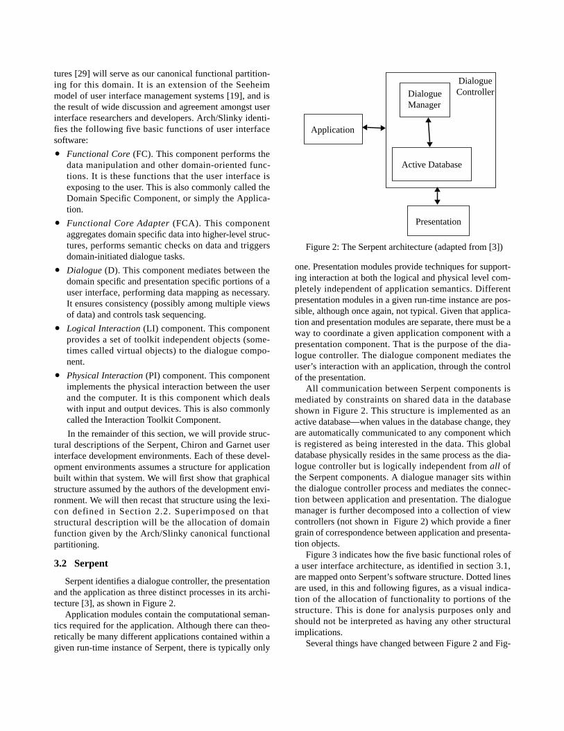
3.2 Serpent
Serpent identifies a dialogue controller, the presentationand the application as three distinct processes in its archi-tecture [3], as shown in Figure 2.
Application modules contain the computational seman-tics required for the application. Although there can theo-retically be many different applications contained within agiven run-time instance of Serpent, there is typically only
one. Presentation modules provide techniques for support-ing interaction at both the logical and physical level com-pletely independent of application semantics. Differentpresentation modules in a given run-time instance are pos-sible, although once again, not typical. Given that applica-tion and presentation modules are separate, there must be away to coordinate a given application component with apresentation component. That is the purpose of the dia-logue controller. The dialogue component mediates theuser’s interaction with an application, through the controlof the presentation.
All communication between Serpent components ismediated by constraints on shared data in the databaseshown in Figure 2. This structure is implemented as anactive database—when values in the database change, theyare automatically communicated to any component whichis registered as being interested in the data. This globaldatabase physically resides in the same process as the dia-logue controller but is logically independent from all ofthe Serpent components. A dialogue manager sits withinthe dialogue controller process and mediates the connec-tion between application and presentation. The dialoguemanager is further decomposed into a collection of viewcontrollers (not shown in Figure 2) which provide a finergrain of correspondence between application and presenta-tion objects.
Figure 3 indicates how the five basic functional roles ofa user interface architecture, as identified in section 3.1,are mapped onto Serpent’s software structure. Dotted linesare used, in this and following figures, as a visual indica-tion of the allocation of functionality to portions of thestructure. This is done for analysis purposes only andshould not be interpreted as having any other structuralimplications.
Several things have changed between Figure 2 and Fig-
DialogueController
Figure 2: The Serpent architecture (adapted from [3])
Active Database
DialogueManager
Application
Presentation
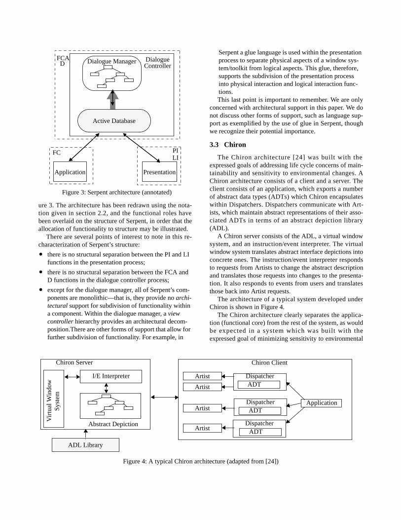
ure 3. The architecture has been redrawn using the nota-tion given in section 2.2, and the functional roles havebeen overlaid on the structure of Serpent, in order that theallocation of functionality to structure may be illustrated.
There are several points of interest to note in this re-characterization of Serpent’s structure:
• there is no structural separation between the PI and LIfunctions in the presentation process;
• there is no structural separation between the FCA andD functions in the dialogue controller process;
• except for the dialogue manager, all of Serpent’s com-ponents are monolithic—that is, they provide no archi-tectural support for subdivision of functionality withina component. Within the dialogue manager, a viewcontroller hierarchy provides an architectural decom-position.There are other forms of support that allow forfurther subdivision of functionality. For example, in
Serpent a glue language is used within the presentationprocess to separate physical aspects of a window sys-tem/toolkit from logical aspects. This glue, therefore,supports the subdivision of the presentation processinto physical interaction and logical interaction func-tions.This last point is important to remember. We are only
concerned with architectural support in this paper. We donot discuss other forms of support, such as language sup-port as exemplified by the use of glue in Serpent, thoughwe recognize their potential importance.
3.3 Chiron
The Chiron architecture [24] was built with theexpressed goals of addressing life cycle concerns of main-tainability and sensitivity to environmental changes. AChiron architecture consists of a client and a server. Theclient consists of an application, which exports a numberof abstract data types (ADTs) which Chiron encapsulateswithin Dispatchers. Dispatchers communicate with Art-ists, which maintain abstract representations of their asso-ciated ADTs in terms of an abstract depiction library(ADL).
A Chiron server consists of the ADL, a virtual windowsystem, and an instruction/event interpreter. The virtualwindow system translates abstract interface depictions intoconcrete ones. The instruction/event interpreter respondsto requests from Artists to change the abstract descriptionand translates those requests into changes to the presenta-tion. It also responds to events from users and translatesthose back into Artist requests.
The architecture of a typical system developed underChiron is shown in Figure 4.
The Chiron architecture clearly separates the applica-tion (functional core) from the rest of the system, as wouldbe expected in a system which was built with theexpressed goal of minimizing sensitivity to environmental
FC PILI
FCAD
Application Presentation
Figure 3: Serpent architecture (annotated)
DialogueController
Dialogue Manager
Active Database
Figure 4: A typical Chiron architecture (adapted from [24])
Abstract Depiction
ADL Library
Vir
tual
Win
dow
Chiron Server
Application
Chiron Client
ADTDispatcherArtist
ADTDispatcher
ADTDispatcher
Artist
Artist
Artist
I/E Interpreter
Syst
em
changes. The dispatchers/ADTs together form the func-tional core adapter. It seems clear that the Artists containsome of the dialogue, for example, maintaining a corre-spondence between objects from the application domainand interface objects from the presentation domain. How-ever, what is less clear, from the architectural description,is where the “state” of the dialogue lives. For example,where does one put the information that the “paste” optionin an edit menu should be grayed out unless something haspreviously been cut or copied? Another type of dialogueissue is maintaining relationships among the interfaceobjects. For example, when a user selects the “Save As”option in a file menu, something in the dialogue mustcause a file selection box to be created. Once again, thelocation of these sorts of dialogue issues is not clear fromChiron’s architectural description. These dependenciesmight exist in the Artists or the ADTs. [28]
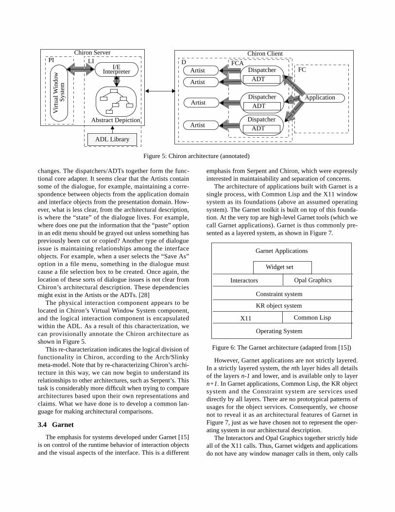
The physical interaction component appears to belocated in Chiron’s Virtual Window System component,and the logical interaction component is encapsulatedwithin the ADL. As a result of this characterization, wecan provisionally annotate the Chiron architecture asshown in Figure 5.
This re-characterization indicates the logical division offunctionality in Chiron, according to the Arch/Slinkymeta-model. Note that by re-characterizing Chiron’s archi-tecture in this way, we can now begin to understand itsrelationships to other architectures, such as Serpent’s. Thistask is considerably more difficult when trying to comparearchitectures based upon their own representations andclaims. What we have done is to develop a common lan-guage for making architectural comparisons.
3.4 Garnet
The emphasis for systems developed under Garnet [15]is on control of the runtime behavior of interaction objectsand the visual aspects of the interface. This is a different
emphasis from Serpent and Chiron, which were expresslyinterested in maintainability and separation of concerns.
The architecture of applications built with Garnet is asingle process, with Common Lisp and the X11 windowsystem as its foundations (above an assumed operatingsystem). The Garnet toolkit is built on top of this founda-tion. At the very top are high-level Garnet tools (which wecall Garnet applications). Garnet is thus commonly pre-sented as a layered system, as shown in Figure 7.
However, Garnet applications are not strictly layered.In a strictly layered system, the nth layer hides all detailsof the layers n-1 and lower, and is available only to layern+1. In Garnet applications, Common Lisp, the KR objectsystem and the Constraint system are services useddirectly by all layers. There are no prototypical patterns ofusages for the object services. Consequently, we choosenot to reveal it as an architectural features of Garnet inFigure 7, just as we have chosen not to represent the oper-ating system in our architectural description.
The Interactors and Opal Graphics together strictly hideall of the X11 calls. Thus, Garnet widgets and applicationsdo not have any window manager calls in them, only calls
Operating System
KR object system
X11 Common Lisp
Constraint system
Interactors Opal Graphics
Widget set
Garnet Applications
Figure 6: The Garnet architecture (adapted from [15])
Abstract Depiction
ADL Library
I/EInterpreter
Vir
tual
Win
dow
Chiron Server
Application
Chiron Client
Artist ADT
Dispatcher
FCD FCALIPI
Artist
Artist
Artist
ADT
Dispatcher
ADT
Dispatcher
Figure 5: Chiron architecture (annotated)
Syst
em
to the interactors, object-oriented graphics, constraints andobject system. [14]
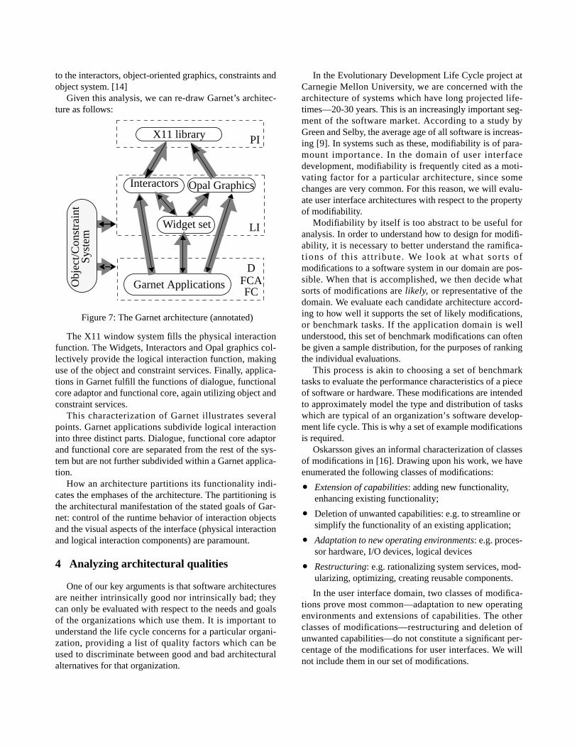
Given this analysis, we can re-draw Garnet’s architec-ture as follows:
The X11 window system fills the physical interactionfunction. The Widgets, Interactors and Opal graphics col-lectively provide the logical interaction function, makinguse of the object and constraint services. Finally, applica-tions in Garnet fulfill the functions of dialogue, functionalcore adaptor and functional core, again utilizing object andconstraint services.
This characterization of Garnet illustrates severalpoints. Garnet applications subdivide logical interactioninto three distinct parts. Dialogue, functional core adaptorand functional core are separated from the rest of the sys-tem but are not further subdivided within a Garnet applica-tion.
How an architecture partitions its functionality indi-cates the emphases of the architecture. The partitioning isthe architectural manifestation of the stated goals of Gar-net: control of the runtime behavior of interaction objectsand the visual aspects of the interface (physical interactionand logical interaction components) are paramount.
4 Analyzing architectural qualities
One of our key arguments is that software architecturesare neither intrinsically good nor intrinsically bad; theycan only be evaluated with respect to the needs and goalsof the organizations which use them. It is important tounderstand the life cycle concerns for a particular organi-zation, providing a list of quality factors which can beused to discriminate between good and bad architecturalalternatives for that organization.
In the Evolutionary Development Life Cycle project atCarnegie Mellon University, we are concerned with thearchitecture of systems which have long projected life-times—20-30 years. This is an increasingly important seg-ment of the software market. According to a study byGreen and Selby, the average age of all software is increas-ing [9]. In systems such as these, modifiability is of para-mount importance. In the domain of user interfacedevelopment, modifiability is frequently cited as a moti-vating factor for a particular architecture, since somechanges are very common. For this reason, we will evalu-ate user interface architectures with respect to the propertyof modifiability.
Modifiability by itself is too abstract to be useful foranalysis. In order to understand how to design for modifi-ability, it is necessary to better understand the ramifica-t ions of this at t r ibute. We look at what sorts ofmodifications to a software system in our domain are pos-sible. When that is accomplished, we then decide whatsorts of modifications are likely, or representative of thedomain. We evaluate each candidate architecture accord-ing to how well it supports the set of likely modifications,or benchmark tasks. If the application domain is wellunderstood, this set of benchmark modifications can oftenbe given a sample distribution, for the purposes of rankingthe individual evaluations.
This process is akin to choosing a set of benchmarktasks to evaluate the performance characteristics of a pieceof software or hardware. These modifications are intendedto approximately model the type and distribution of taskswhich are typical of an organization’s software develop-ment life cycle. This is why a set of example modificationsis required.
Oskarsson gives an informal characterization of classesof modifications in [16]. Drawing upon his work, we haveenumerated the following classes of modifications:
• Extension of capabilities: adding new functionality,enhancing existing functionality;
• Deletion of unwanted capabilities: e.g. to streamline orsimplify the functionality of an existing application;
• Adaptation to new operating environments: e.g. proces-sor hardware, I/O devices, logical devices
• Restructuring: e.g. rationalizing system services, mod-ularizing, optimizing, creating reusable components.
In the user interface domain, two classes of modifica-tions prove most common—adaptation to new operatingenvironments and extensions of capabilities. The otherclasses of modifications—restructuring and deletion ofunwanted capabilities—do not constitute a significant per-centage of the modifications for user interfaces. We willnot include them in our set of modifications.
Figure 7: The Garnet architecture (annotated)
X11 library
Interactors Opal Graphics
Widget set
Garnet Applications FCAFC
PI
D
LI
Obj
ect/C
onst
rain
t S
yste
m
Adaptation to new operating environments is a commonmodification activity which user interface architecturesmust support. For example, this paper is being composedusing a desktop publishing system which is available onUnix-based workstations running the X window system,Macintoshes running the Macintosh toolkit, and IBM-compatible PCs, running MS-Windows. In each of thesecases, the underlying functionality of the system is identi-cal. What does change are the devices, both logical andphysical, used to interact with the program.
The first of our benchmark modification tasks, there-fore, is to change the toolkit. For example, a move fromusing Motif to Fresco would be typical of this category ofmodification.
Because user interface development is highly iterative,extensions of capabilities (adding new features, reorganiz-ing the appearance of the interface, reorganizing thehuman-computer dialogue) occur frequently. This is par-ticularly so during the initial development of a user inter-face, but such modifications are also common later in thelife cycle.
The user interface life cycle is distinguished from typi-cal software engineering life cycles because it is highlyiterative, relying more on prototyping and empirical test-ing and validation. Requirements for human-computerinteraction are often not well understood in advance, andso iteration and prototyping are often the only ways inwhich to evolve a system’s design. Thus this class ofchange is the most common (and most costly overall) inthe user interface life cycle.
We choose as our second benchmark task a modifica-tion to the human-computer dialogue. More specifically,the second benchmark modification is to add a singleoption to a menu, reflecting some piece of applicationfunctionality which must be made available to a user.
5 Architectural analysis for UI tools
Now that we have enumerated our set of benchmarkmodifications—changing the window system/toolkit andadding a single option to a menu—we are in a position toevaluate the degree to which each of our candidate systemsprovides architectural support for these modifications.
5.1 Serpent
5.1.1 Changing the toolkit
Changing the toolkit in Serpent assumes that we havean application running under one toolkit and we want tochange to another toolkit which is not currently supportedwithin the Serpent run-time environment. For example,this situation would occur if we had Motif running in aSerpent presentation process and we want to replace it
with OpenLook. What would have to change is both thepresentation process and the dialogue.
There are two ways this change can be accommodatedin Serpent. If the intended use of the new toolkit is simplyto reproduce the look and feel of the old toolkit, then theonly modification necessary is to change Serpent’s gluecode in the presentation process. As discussed in Section3.2, the glue code provides the logical interaction functionfor Serpent, but is not isolated in its architectural descrip-tion, so we conclude that Serpent provides no architecturalsupport for this kind of modification. If the intended use ofthe new toolkit is to provide new interaction capability,then modifications to the dialogue manager would be nec-essary, in addition to new glue code.
We can see from this analysis the purpose of the logicalinteraction function in the Arch/Slinky canonical partition-ing. Logical interaction provides a buffer between the dia-logue and the physical interaction in order to isolate theeffect of changes between them. Architectures that isolatethe logical interaction function provide support for thisbenchmark modification. Serpent, therefore, does not pro-vide architectural support for this modification.
5.1.2 Adding a menu option
Serpent has isolated the dialogue controller, so it is easyto say that the second modification type—adding anoption to a menu—will occur somewhere in that process.The dialogue controller process contains two parts, thedialogue manager, which governs the behavior of the dia-logue and the active database, which maintains the state ofthe dialogue. The benchmark modification concerns achange in the behavior of the dialogue, so it is isolated inthe dialogue manager. View controllers further subdividethe dialogue manager so that it easier to isolate a specificpiece of dialogue behavior, such as a menu. Therefore, weconclude that Serpent provides adequate architectural sup-port for this modification.
5.2 Chiron
5.2.1 Changing the toolkit
Chiron goes one step beyond Serpent in providingarchitectural support for this modification. Chiron has iso-lated the logical and physical interaction functions in sepa-rate structures within a Chiron server. Since the VirtualWindow System only communicates with the Instruction/Event Interpreter and its associated Abstract DepictionLibrary, it is isolated from the rest of the architecture. Thisarchitectural isolation means that the Virtual Window Sys-tem and Instruction/Even Interpreter communicate via awell-defined interface. The existence of such an interfacemeans that different toolkits could be inserted into the
architecture as long as they comply with the interface con-ventions.
This strict separation of concerns aids modifiability, bylocalizing the effects of a change. Thus, we can concludethat the Chiron architecture provides significant supportfor this benchmark modification.
5.2.2 Adding a menu option
Chiron fares slightly less well with respect to the sec-ond modification. As stated in section 3.3, the division ofdialogue responsibilities between Artists and ADTs is notprecisely specified. Hence, a modification to the dialoguemay manifest itself as a change to an Artist or an ADT, orboth. If the ADTs are well-structured, changes to themshould be minimal, in which case a change to the dialoguewould be isolated to the Artists.
For this particular modification, it is reasonable toassume that no change to an ADT would be necessarysince we are assuming that we want to make availablesome pre-existing application function which wouldalready be defined in one ADT. The modification in thiscase is restricted to an Artist which is associated to theADT containing the desired function. We conclude thatChiron provides architectural support for this benchmarkmodification.
5.3 Garnet
5.3.1 Changing the toolkit
Garnet has isolated the toolkit to three components—interactors, Opal graphics and widgets—and has hiddenany X11 dependencies behind them. Garnet has strictlyseparated physical interaction, and so we conclude thatthis modification is supported by the architecture.
5.3.2 Adding a menu option
A dialogue in Garnet is monolithic, and can involve anyof the language services which Garnet provides. Thus,changing a menu in Garnet involves locating and modify-ing the affected Lisp code, which may be a difficult task ina complex interface. The second modification is not archi-tecturally supported by Garnet. Garnet does provide tooland language support for this class of change, but as westated earlier, that is not the concern of this paper.
6 Conclusions and future work
In this paper, we have provided a architectural analysismethod (SAAM) and used it to evaluate user interfacesarchitectures with respect to modifiability. This method isbased upon a common understanding and representationfor architectures and an analysis of an organization’s life-
cycle requirements. SAAM permits the comparison ofarchitectures within the context of an organization’s par-ticular needs. This sort of comparison has been hithertoquite difficult.
The SAAM places strong demands on an organizationto articulate those quality attributes of primary impor-tance. It also require a selection of benchmark tasks withwhich to test those attributes. The purpose of the SAAM isnot to criticize or commend particular architectures, but toprovide a method for determining which architecture sup-ports an organization’s needs.
We applied the method to evaluate user interface devel-opment environments to determine their architectural sup-port for two benchmark modifiability tasks. We saw thatthe benchmark tasks could be cast in terms of the Arch/Slinky metamodel. Therefore, systems with a clear alloca-tion of that functional partitioning to their structure couldprovide architectural support for the modifications. Weemphasize that architectural support for a quality attributeis only one possible type of support. We may also havelanguage or tool support. We recognize that an analysis ofthese other types of support is an important topic for futureresearch.
Quality attributes is a recognized driver for softwarearchitectural design, outside of the user interface domain(e.g. [1]). Consequently, we believe SAAM will work forother attributes. This method of evaluation shows thedegree to which an architecture was designed to supportselected quality attributes. We see a strong link betweenquality attributes and canonical partitionings. More thanone canonical partitioning is possible for a given domain,each accommodating a different set of quality attributes[5]. For example, the multiagent PAC model [7] is a candi-date canonical partitioning which emphasizes scalabilityand construction efficiency.
Finally, what is really desirable is to have metrics formore precisely evaluating attributes in terms of architec-tures, but our understanding of this topic is not yet suffi-cient to define any measurements. For now, we simplyhave ways to analyze, compare and rank architectures. Webelieve that the work of Henry and Kafura [10] on infor-mation flow points the way to an analysis technique forarchitectures, but it must be augmented by techniques formeasuring the understandability and consistency of archi-tectures.
7 Acknowledgments
We would very much like to thank Brian Boesch ofARPA and Dick Martin of the School of Computer Sci-ence at CMU for their support of this research. We alsothank members of the IFIP Working Group 2.7 (UserInterface Engineering) and colleagues at the SEI, specifi-
cally Reed Little and Larry Howard, for their influenceduring the formative stages of this work. This work wassponsored in part by the National Sciences and Engineer-ing Research Council of Canada and the U.S. Departmentof Defense.
8 References
[1] Abowd, G., Bass, L., Howard, L., Northrop, L. “StructuralModeling: an Application Framework and Development Processfor Flight Simulators”. Software Engineering Institute, CarnegieMellon University Technical Report CMU-SEI-TR-93-14. Pitts-burgh, PA, 1993.
[2] Abowd. G., Allen, R., Garlan, G. “Using Style to UnderstandDescriptions of Software Architectures”. Software EngineeringNotes, 18(5):9-20, 1993. Proceedings of SIGSOFT ‘93: Sympo-sium on the Foundations of Software Engineering.
[3] Bass, L., Clapper, B., Hardy, E., Kazman, R., Seacord, R.“Serpent: A User Interface Management System”. Proceedings ofthe Winter 1990 USENIX Conference, Berkeley, CA, January1990, 245-258.
[4] Bass, L. and Coutaz, J. Developing Software for the UserInterface, Addison-Wesley, 1991.
[5] Bass, L. Kazman, R. and Abowd, G. “Issues in the Evaluationof User Interface Tools”. Proceedings of the ICSE Workshop onSoftware Engineering and Human-Computer Interaction, Sor-rento, Italy, May, 1993. Forthcoming
[6] Briand, L.C., Morasca, S. and Basili, V.R. “Measuring andAssessing Maintainability at the End of High Level Design”, Pro-ceedings of the IEEE conference on Software Maintenance,Montreal, Canada, 1993.
[7] Coutaz, J. “PAC, An Implementation Model for DialogDesign”, Proceedings of Interact ‘87, Stuttgart, September, 1987,431-436.
[8] Garlan, D., Shaw, M. “An Introduction to Software Architec-ture”. Advances in Software Engineering and KnowledgeEngineering, Volume I, World Scientific Publishing, 1993.Forthcoming.
[9] Green, J., Selby, B. “Dynamic Planning and Software Mainte-nance: A Fiscal Approach”, Naval Postgraduate School,Monterey, CA, NTIS Report AD-A112 801/6, 1981.
[10] Henry, S., Kafura, D. “Software Structure Metrics Based onInformation Flow”, IEEE Transactions on Software Engineering,SE-7(5), Sept. 1981.
[11] Hix, D. “Generations of User-Interface Management Sys-tems”, IEEE Software, 7(5):77-87, 1990.
[12] Kazman, R., Abowd, G., Bass, L., Webb, M., “Analyzing theProperties of User Interface Software Architectures,” CarnegieMellon University, School of Computer Science Technical ReportCMU-CS-93-201, 1993.
[13] Military Standard, Defense System Software Development(DOD-STD-2167A). Washington, D.C.: United States Depart-ment of Defense, 1988.
[14] Myers, B., Giuse, D., Dannenberg, R., et al., “The GarnetReference Manuals”, School of Computer Science, CarnegieMellon University Technical Report CMU-CS-90-117-R3, 1992.
[15] Myers, B., Giuse, D., Dannenberg, R., et al. “Garnet: Com-prehensive Support for Graphical, Highly Interactive User
Interfaces”, IEEE Computer, 23(11): 71-85.
[16] Oskarsson, Ö. “Mechanisms of Modifiability in Large Soft-ware Systems”, Linköping Studies in Science and TechnologyDissertations No. 77, 1982.
[17] Parnas, D.L. “On the Criteria To Be Used in DecomposingSystems into Modules”, Communications of the ACM,15(12):1053-1058, 1972.
[18] Perry, D., Wolf, A. “Foundations for the study of softwarearchitecture”, SIGSOFT Software Engineering Notes, 17(4),October 1992, 40-52.
[19] Pfaff, G. (ed.). User Interface Management Systems. NewYork: Springer-Verlag, 1985.
[20] Pittman, J., Kitrick, C. “VUIMS: A Visual User InterfaceManagement System”, Proceedings of the ACM SIGGRAPHSymposium on User Interface Software and Technology, Snow-bird, UT, October 1990, 36-46.
[21] Pressman, R. Software Engineering: a Practitioner’sApproach, 3rd edition. New York: McGraw-Hill, 1992.
[22] Rumbaugh, J., Blaha, M., Premerlani, W., Eddy, F., Loren-son, W. Object-Oriented Modeling and Design, EnglewoodCliffs, N.J.: Prentice-Hall, 1991.
[23] SEI, “Serpent Overview,” SEI Technical Report CMU/SEI-89-UG-2, Carnegie Mellon University Software EngineeringInstitute, August 1989.
[24] Sommerville, I. Software Engineering, 4th edition. Reading,MA: Addison-Wesley, 1992.
[25] Stevens, W.P., Myers, G.J. and Constantine, L.L. “Structureddesign” IBM Systems Journal, 13(2):115-139, 1974.
[26] Szekely, P. “Standardizing the Interface Between Applica-tions and UIMSs”, Proceedings of the ACM SIGGRAPHSymposium on User Interface Software and Technology, Will-iamsburg, VA, November 1989, 34-42.
[27] Taylor, R., Johnson, G. “Separations of Concerns in the Chi-ron-1 User Interface Development and Management System,”Proceedings of InterCHI ‘93, Amsterdam, May 1993, 367-374.
[28] Taylor, R. personal communication, July 1993.
[29] UIMS Tool Developers Workshop, “A Metamodel for theRuntime Architecture of an Interactive System”, SIGCHI Bulle-tin, 24(1), 32-37.
[30] Yourdon, E. Modern Structured Analysis, Englewood Cliffs,N.J.: Prentice-Hall, 1989.