Embed Size (px)
Citation preview
Page 1 CT8 CT10960.065 Rev # 0
SOUND ADVANCESA R
INSTALLATION INSTRUCTIONS
CT8B/CT10B series Loudspeakerwith Accesories
MODEL: CT8BH, CT8BHT, CT8BS, CT8BST, CT8BHG*, CT8BSG*,CT8BHTG*, CT8BSTG*, CT8BHTF*, CT8BSTF*CT10BH, CT10BHT, CT10BS, CT10BST, CT10BHG*, CT10BSG*,CT10BHTG*, CT10BSTG*, CT10BHTF*, CT10BSTF**”G” General Signaling UL1480 (UEAY) “F” Fire Protective SignalingUL1480 (UUMW)
APPLICATIONS: Installation into sheetrock ceilings** ,Installation into drop ceilings**Installation into Concealed Spline Ceilings**, Installation into walls****with or without backbox - new or existing construction
REQUIRED ACCESSORIES: See Text
TECHNICAL SPECIFICATIONS
DIMENSIONSUnless otherwise specified all dimensions are ininches (mm)
2.33 [59]
.37 [9]13.00 [330]
CT8BS, CT8BST, CT8BSG, CT8BSTG, CT8BSTF
11.2
5 [2
86]
2.33 [59]
.37 [9]13.00 [330]
CT8BH, CT8BHT, CT8BHG, CT8BHTG, CT8BHTF
11.2
5 [2
86]
2.49 [63]
.55 [14]13.00 [330]
CT10BH, CT10BHT, CT10BHG, CT10BHTG, CT10BHTF
Page 2CT8 and CT10 960.065 Rev # 0
PRODUCT WEIGHTCT8BH, CT8BS, CT8BHG, CT8BSG 3.6 lb. (1.65kg.)
CT8BHT, CT8BST, CT8BHTG, CT8BSTG,CT8BHTF, CT8BSTF 4.1 lb. (1.88 kg.)
CT10BH, CT10BS, CT10BHG, CT10BSG 3.6 lb.(1.64 kg.)
CT10BHT, CT10BST, CT10BHTG, CT10BSTG,CT10BHTF, CT10BSTF 4.2 lb. (1.91 kg.)
MODELS
CT8B SERIESCT8BH - 8 ohm, with standard screw mountinghardware
CT8BHT - as above with 8W\70.7V or 100V trans-former
CT8BS - 8 ohm, with torsion spring mountinghardware
CT8BST - as above with 8W\70.7V or 100V trans-former
UL LISTED (GENERAL SIGNALING)CT8BHG - 8 ohm, with standard screw mountinghardware
CT8BHTG - as above with 8W\70.7V transformer
CT8BSG - 8 ohm, with torsion spring mountinghardware
CT8BSTG - as above with 8W\70.7V transformer
UL LISTED (FIRE PROTECTIVE SIGNAL-ING)
CT8BHTF - with standard screw mountinghardware and 8W\70.7V transformer
CT8BSTF - with torsion spring mounting hardwareand 8W\70.7V transformer
CT10B SERIESCT10BH - 8 ohm, with stud/nut mounting hard-
wareCT10BHT - as above with 8W\70.7V or 100V
transformerCT10BS - 8 ohm, with torsion spring mounting
hardwareCT10BST - as above with 8W\70.7V or 100V
transformer
UL LISTED (GENERAL SIGNALING)CT10BHG - 8 ohm, with stud/nut mounting
hardwareCT10BHTG - as above with 8W\70.7V transformerCT10BSG - 8 ohm, with torsion spring mounting
hardwareCT10BSTG - as above with 8W\70.7V transformer
UL LISTED (FIRE PROTECTIVE SIGNAL-ING)
CT10BHTF - with stud/nut mounting hardwareand 8W\70.7V transformer
CT10BSTF - with torsion spring mounting hard-ware and 8W\70.7V transformer
Please Note: Additional information on all ULListed models and compatible accessories iscovered in a separate section of these instruc-tions. More detailed information can be foundon the SOUND ADVANCE 960.060 Rev. 0 DataSheet. Please contact the factory for a copy ifrequired.
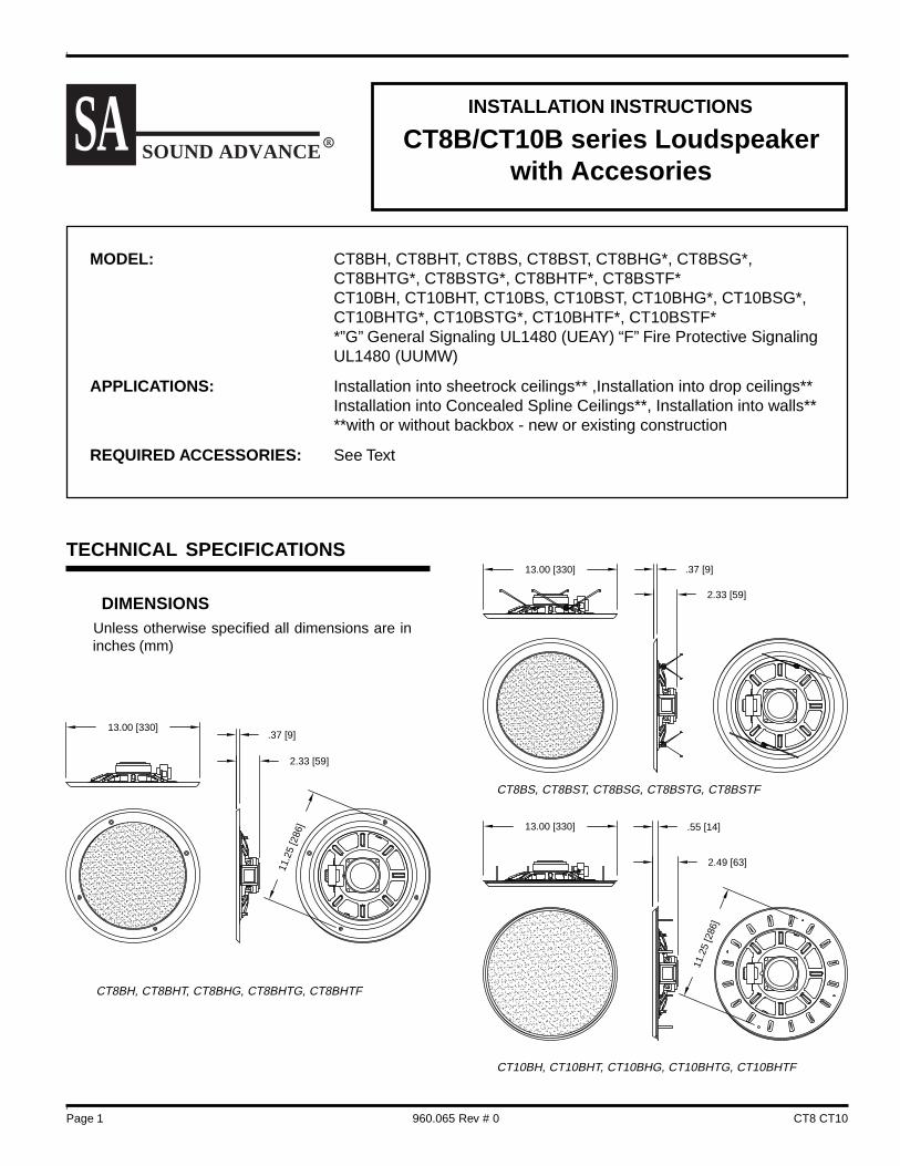
CT10BS, CT10BST, CT10BSG, CT10BSTG, CT10BSTF
2.49 [63]
.56 [14]13.00 [330]
Page 3 CT8 CT10960.065 Rev # 0
ACCCESORY DATA
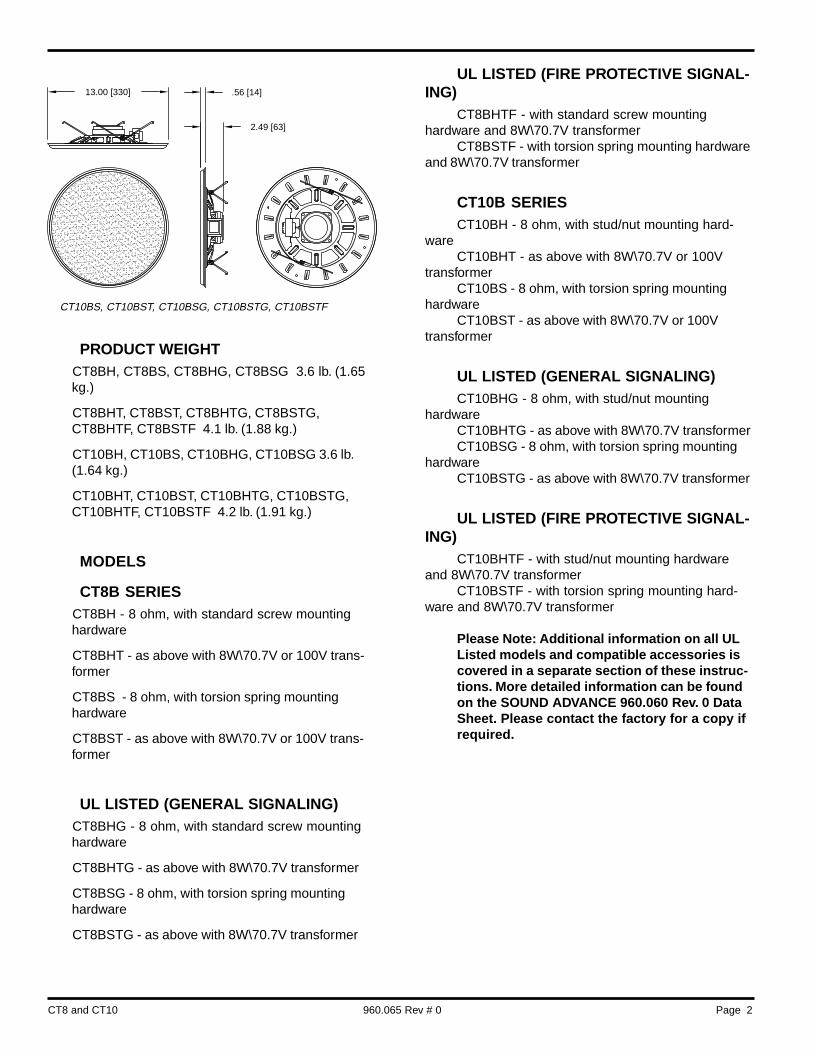
PBB8-10 Industry Standard Stackable Enclosure(Backcan)
Weight 1.9 lb. (0.86 kg.)
TBS8-10 T-Bar Support Bridge (Tile Bridge), foruse with or without backcan.
Weight 1.3 lb. (0.61 kg.)
The CT8B/CT10B Series loudspeakers can beinstalled using most industry standard 8" loudspeakermounting accessories and will retrofit into almost allexisting standard 8" diameter loudspeaker openings.
MOUNTING LOCATIONSSOUND ADVANCE products provide outstanding
performance and economic advantages when installedin environments with an ambient noise level at or below75dBA, where the speakers can be placed between 8and 18 feet above the floor, and which are large enoughto accommodate at least 4 or more conventional loud-speakers. When system design requirements indicatespeaker to speaker distances of greater than 40.0 ft.,please contact the factory for additional technical
information on such applications.
SOUND ADVANCE recommends mounting theCT8B/CT10B Series in:
Suspended CeilingsWood or Metal Stud Walls and CeilingsMost Soffits and FasciaRetrofit into almost all standard 8" Loudspeaker
Openings
RECOMMENDED ENVIRONMENTS
CT8B/CT10B Series:Indoor or Weather Protected Outdoor
UL Listed Models are for indoor use only
RECCOMMENDED FINISHThe flat Expanded Polystyrene [EPS] loudspeaker
surface may be finished with water soluble materialssuch as latex paints, to match any decor or colorrequirement, using conventional brush-on, roller orairless spray application systems.
UNPACKING AND INSPECTION
Open the shipping cartons carefully and remove allcontents. Inspect the product and accessories fordamage. Report damage or shortages to SOUNDADVANCE SYSTEMS INC., immediately.
CAUTION: SOUND ADVANCE loudspeakers utilizea flat polystyrene material as the sound-radiatingsurface. Although it is resistant to mechanical dam-age and is unaffected by environmental extremes,care should be observed during handling, to avoidpunctures or other damage.
CAUTION: DO NOT remove the protective card-board disk until loudspeaker has been connectedand properly secured.
INSTALLATION
The notes below are intended to provide generalinformation and assistance in the installation of CT8B/
4.25 [108]
12.25 [311]
10.25 [260]
.60 [15]
14.38 [365]
13.38 [340]
23.75 [603]
Page 4CT8 and CT10 960.065 Rev # 0
CT10B Series products and their compatible hardwarein a variety of situations, and shall not be used as astep-by-step installation guide.
Although the CT8B/CT10B Series loudspeakerscan be installed using most industry-standard 8"loudspeaker mounting accessories, certain require-ments or restrictions of use may apply. Please reviewthe following notes and recommendations to assure all
installation prerequisites will be met.
THESE NOTES ARE EXTREMELY IMPORTANT ANDSHOULD BE READ PRIOR TO BEGINNING ANY IN-STALLATION.
Once reviewed, please proceed to the “Loud-
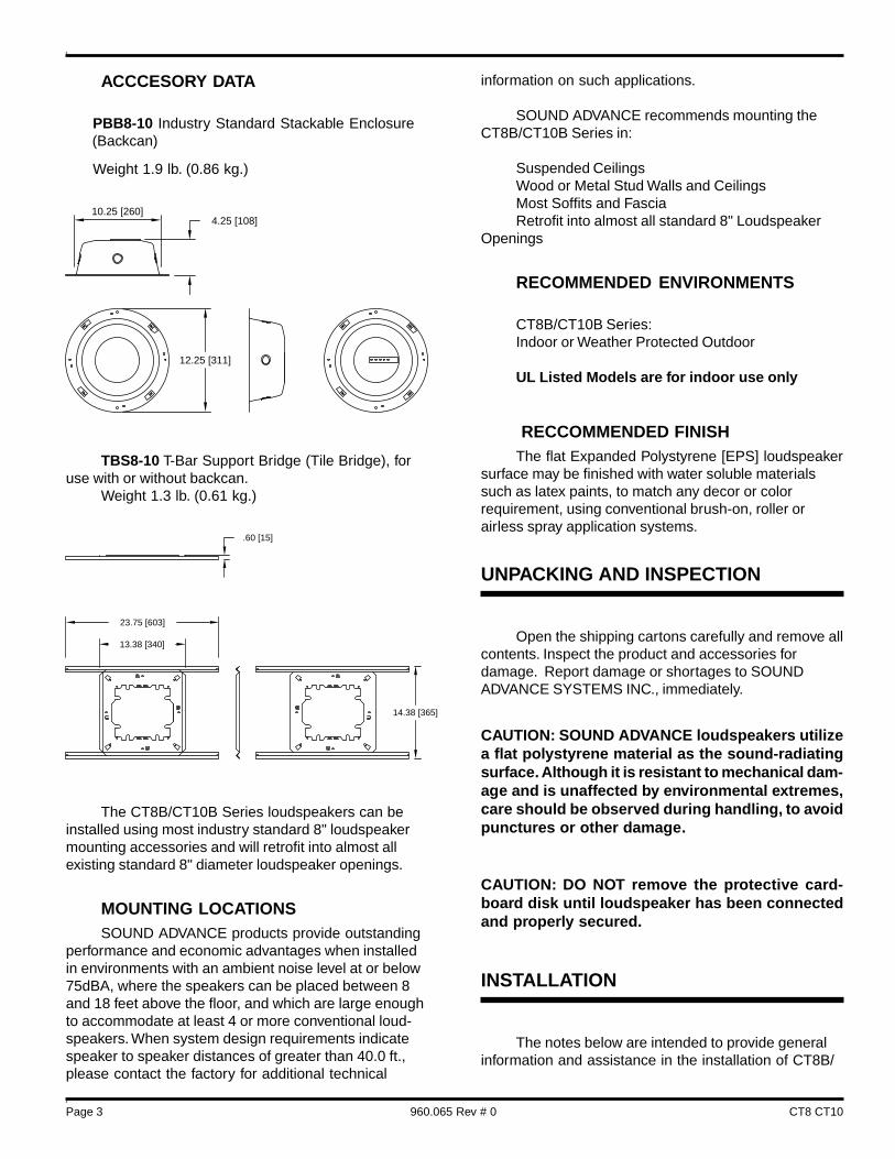
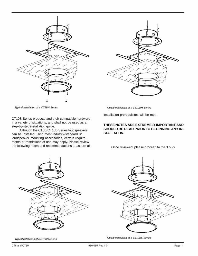
Typical nstallation of a CT8BH Series
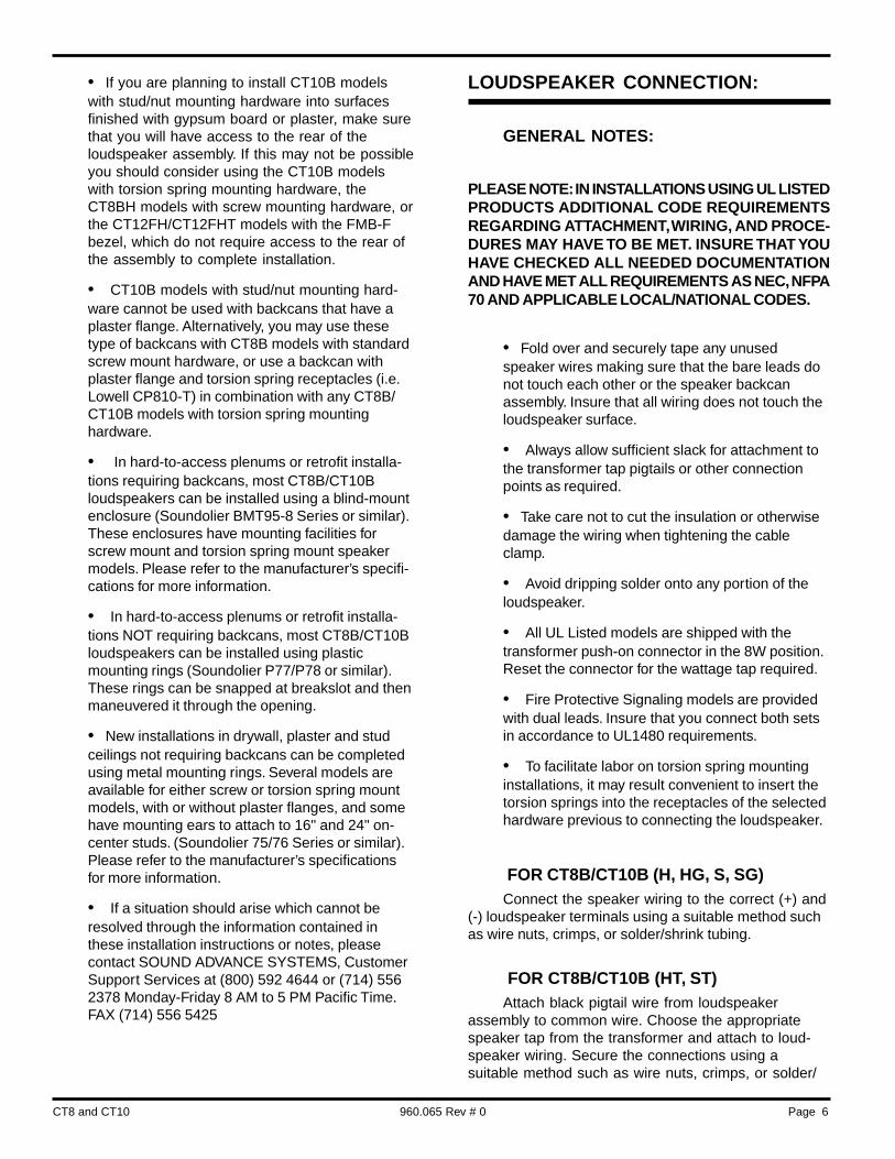
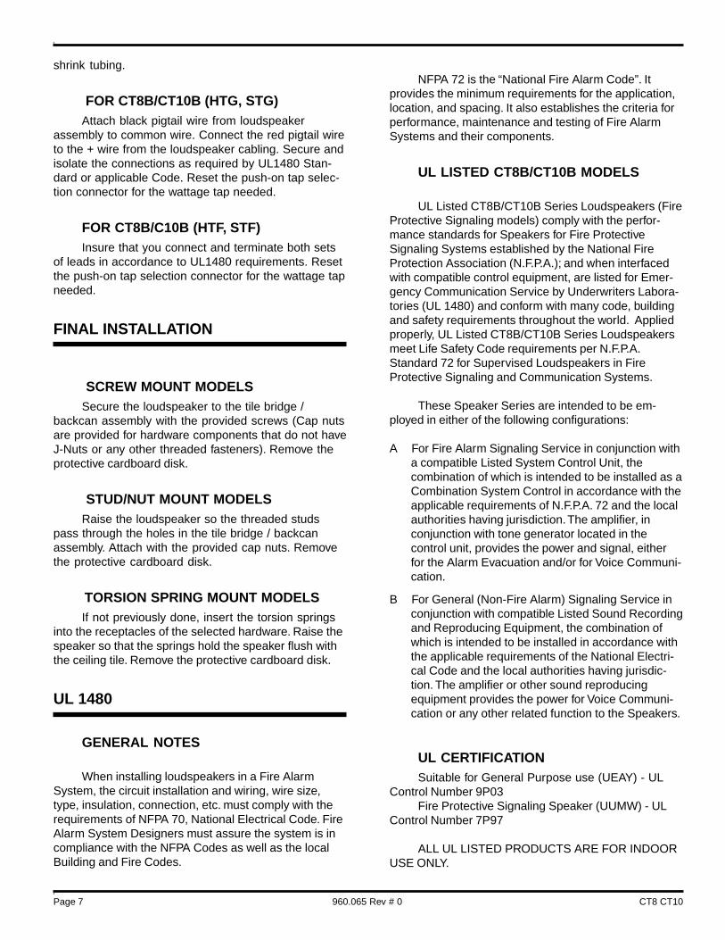
Typical nstallation of a CT8BS Series Typical nstallation of a CT10BS Series
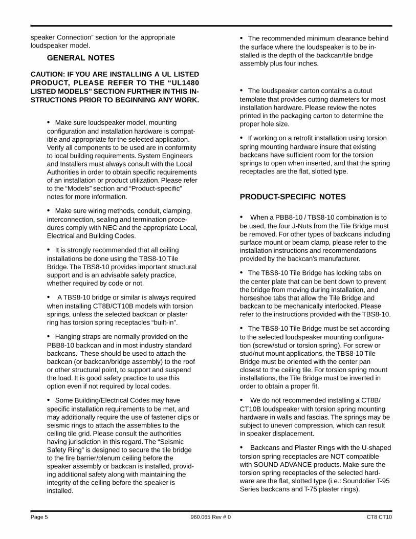
Typical nstallation of a CT10BH Series
Page 5 CT8 CT10960.065 Rev # 0
speaker Connection” section for the appropriateloudspeaker model.
GENERAL NOTES
CAUTION: IF YOU ARE INSTALLING A UL LISTEDPRODUCT, PLEASE REFER TO THE “UL1480LISTED MODELS” SECTION FURTHER IN THIS IN-STRUCTIONS PRIOR TO BEGINNING ANY WORK.
• Make sure loudspeaker model, mountingconfiguration and installation hardware is compat-ible and appropriate for the selected application.Verify all components to be used are in conformityto local building requirements. System Engineersand Installers must always consult with the LocalAuthorities in order to obtain specific requirementsof an installation or product utilization. Please referto the “Models” section and “Product-specific”notes for more information.
• Make sure wiring methods, conduit, clamping,interconnection, sealing and termination proce-dures comply with NEC and the appropriate Local,Electrical and Building Codes.
• It is strongly recommended that all ceilinginstallations be done using the TBS8-10 TileBridge. The TBS8-10 provides important structuralsupport and is an advisable safety practice,whether required by code or not.
• A TBS8-10 bridge or similar is always requiredwhen installing CT8B/CT10B models with torsionsprings, unless the selected backcan or plasterring has torsion spring receptacles “built-in”.
• Hanging straps are normally provided on thePBB8-10 backcan and in most industry standardbackcans. These should be used to attach thebackcan (or backcan/bridge assembly) to the roofor other structural point, to support and suspendthe load. It is good safety practice to use thisoption even if not required by local codes.
• Some Building/Electrical Codes may havespecific installation requirements to be met, andmay additionally require the use of fastener clips orseismic rings to attach the assemblies to theceiling tile grid. Please consult the authoritieshaving jurisdiction in this regard. The “SeismicSafety Ring” is designed to secure the tile bridgeto the fire barrier/plenum ceiling before thespeaker assembly or backcan is installed, provid-ing additional safety along with maintaining theintegrity of the ceiling before the speaker isinstalled.
• The recommended minimum clearance behindthe surface where the loudspeaker is to be in-stalled is the depth of the backcan/tile bridgeassembly plus four inches.
• The loudspeaker carton contains a cutouttemplate that provides cutting diameters for mostinstallation hardware. Please review the notesprinted in the packaging carton to determine theproper hole size.
• If working on a retrofit installation using torsionspring mounting hardware insure that existingbackcans have sufficient room for the torsionsprings to open when inserted, and that the springreceptacles are the flat, slotted type.
PRODUCT-SPECIFIC NOTES
• When a PBB8-10 / TBS8-10 combination is tobe used, the four J-Nuts from the Tile Bridge mustbe removed. For other types of backcans includingsurface mount or beam clamp, please refer to theinstallation instructions and recommendationsprovided by the backcan’s manufacturer.
• The TBS8-10 Tile Bridge has locking tabs onthe center plate that can be bent down to preventthe bridge from moving during installation, andhorseshoe tabs that allow the Tile Bridge andbackcan to be mechanically interlocked. Pleaserefer to the instructions provided with the TBS8-10.
• The TBS8-10 Tile Bridge must be set accordingto the selected loudspeaker mounting configura-tion (screw/stud or torsion spring). For screw orstud/nut mount applications, the TBS8-10 TileBridge must be oriented with the center panclosest to the ceiling tile. For torsion spring mountinstallations, the Tile Bridge must be inverted inorder to obtain a proper fit.
• We do not recommended installing a CT8B/CT10B loudspeaker with torsion spring mountinghardware in walls and fascias. The springs may besubject to uneven compression, which can resultin speaker displacement.
• Backcans and Plaster Rings with the U-shapedtorsion spring receptacles are NOT compatiblewith SOUND ADVANCE products. Make sure thetorsion spring receptacles of the selected hard-ware are the flat, slotted type (i.e.: Soundolier T-95Series backcans and T-75 plaster rings).
Page 6CT8 and CT10 960.065 Rev # 0
• If you are planning to install CT10B modelswith stud/nut mounting hardware into surfacesfinished with gypsum board or plaster, make surethat you will have access to the rear of theloudspeaker assembly. If this may not be possibleyou should consider using the CT10B modelswith torsion spring mounting hardware, theCT8BH models with screw mounting hardware, orthe CT12FH/CT12FHT models with the FMB-Fbezel, which do not require access to the rear ofthe assembly to complete installation.
• CT10B models with stud/nut mounting hard-ware cannot be used with backcans that have aplaster flange. Alternatively, you may use thesetype of backcans with CT8B models with standardscrew mount hardware, or use a backcan withplaster flange and torsion spring receptacles (i.e.Lowell CP810-T) in combination with any CT8B/CT10B models with torsion spring mountinghardware.
• In hard-to-access plenums or retrofit installa-tions requiring backcans, most CT8B/CT10Bloudspeakers can be installed using a blind-mountenclosure (Soundolier BMT95-8 Series or similar).These enclosures have mounting facilities forscrew mount and torsion spring mount speakermodels. Please refer to the manufacturer’s specifi-cations for more information.
• In hard-to-access plenums or retrofit installa-tions NOT requiring backcans, most CT8B/CT10Bloudspeakers can be installed using plasticmounting rings (Soundolier P77/P78 or similar).These rings can be snapped at breakslot and thenmaneuvered it through the opening.
• New installations in drywall, plaster and studceilings not requiring backcans can be completedusing metal mounting rings. Several models areavailable for either screw or torsion spring mountmodels, with or without plaster flanges, and somehave mounting ears to attach to 16" and 24" on-center studs. (Soundolier 75/76 Series or similar).Please refer to the manufacturer’s specificationsfor more information.
• If a situation should arise which cannot beresolved through the information contained inthese installation instructions or notes, pleasecontact SOUND ADVANCE SYSTEMS, CustomerSupport Services at (800) 592 4644 or (714) 5562378 Monday-Friday 8 AM to 5 PM Pacific Time.FAX (714) 556 5425
LOUDSPEAKER CONNECTION:
GENERAL NOTES:
PLEASE NOTE: IN INSTALLATIONS USING UL LISTEDPRODUCTS ADDITIONAL CODE REQUIREMENTSREGARDING ATTACHMENT, WIRING, AND PROCE-DURES MAY HAVE TO BE MET. INSURE THAT YOUHAVE CHECKED ALL NEEDED DOCUMENTATIONAND HAVE MET ALL REQUIREMENTS AS NEC, NFPA70 AND APPLICABLE LOCAL/NATIONAL CODES.
• Fold over and securely tape any unusedspeaker wires making sure that the bare leads donot touch each other or the speaker backcanassembly. Insure that all wiring does not touch theloudspeaker surface.
• Always allow sufficient slack for attachment tothe transformer tap pigtails or other connectionpoints as required.
• Take care not to cut the insulation or otherwisedamage the wiring when tightening the cableclamp.
• Avoid dripping solder onto any portion of theloudspeaker.
• All UL Listed models are shipped with thetransformer push-on connector in the 8W position.Reset the connector for the wattage tap required.
• Fire Protective Signaling models are providedwith dual leads. Insure that you connect both setsin accordance to UL1480 requirements.
• To facilitate labor on torsion spring mountinginstallations, it may result convenient to insert thetorsion springs into the receptacles of the selectedhardware previous to connecting the loudspeaker.
FOR CT8B/CT10B (H, HG, S, SG)Connect the speaker wiring to the correct (+) and
(-) loudspeaker terminals using a suitable method suchas wire nuts, crimps, or solder/shrink tubing.
FOR CT8B/CT10B (HT, ST)Attach black pigtail wire from loudspeaker
assembly to common wire. Choose the appropriatespeaker tap from the transformer and attach to loud-speaker wiring. Secure the connections using asuitable method such as wire nuts, crimps, or solder/
Page 7 CT8 CT10960.065 Rev # 0
shrink tubing.
FOR CT8B/CT10B (HTG, STG)Attach black pigtail wire from loudspeaker
assembly to common wire. Connect the red pigtail wireto the + wire from the loudspeaker cabling. Secure andisolate the connections as required by UL1480 Stan-dard or applicable Code. Reset the push-on tap selec-tion connector for the wattage tap needed.
FOR CT8B/C10B (HTF, STF)Insure that you connect and terminate both sets
of leads in accordance to UL1480 requirements. Resetthe push-on tap selection connector for the wattage tapneeded.
FINAL INSTALLATION
SCREW MOUNT MODELSSecure the loudspeaker to the tile bridge /
backcan assembly with the provided screws (Cap nutsare provided for hardware components that do not haveJ-Nuts or any other threaded fasteners). Remove theprotective cardboard disk.
STUD/NUT MOUNT MODELSRaise the loudspeaker so the threaded studs
pass through the holes in the tile bridge / backcanassembly. Attach with the provided cap nuts. Removethe protective cardboard disk.
TORSION SPRING MOUNT MODELSIf not previously done, insert the torsion springs
into the receptacles of the selected hardware. Raise thespeaker so that the springs hold the speaker flush withthe ceiling tile. Remove the protective cardboard disk.
UL 1480
GENERAL NOTES
When installing loudspeakers in a Fire AlarmSystem, the circuit installation and wiring, wire size,type, insulation, connection, etc. must comply with therequirements of NFPA 70, National Electrical Code. FireAlarm System Designers must assure the system is incompliance with the NFPA Codes as well as the localBuilding and Fire Codes.
NFPA 72 is the “National Fire Alarm Code”. Itprovides the minimum requirements for the application,location, and spacing. It also establishes the criteria forperformance, maintenance and testing of Fire AlarmSystems and their components.
UL LISTED CT8B/CT10B MODELS
UL Listed CT8B/CT10B Series Loudspeakers (FireProtective Signaling models) comply with the perfor-mance standards for Speakers for Fire ProtectiveSignaling Systems established by the National FireProtection Association (N.F.P.A.); and when interfacedwith compatible control equipment, are listed for Emer-gency Communication Service by Underwriters Labora-tories (UL 1480) and conform with many code, buildingand safety requirements throughout the world. Appliedproperly, UL Listed CT8B/CT10B Series Loudspeakersmeet Life Safety Code requirements per N.F.P.A.Standard 72 for Supervised Loudspeakers in FireProtective Signaling and Communication Systems.
These Speaker Series are intended to be em-ployed in either of the following configurations:
A For Fire Alarm Signaling Service in conjunction witha compatible Listed System Control Unit, thecombination of which is intended to be installed as aCombination System Control in accordance with theapplicable requirements of N.F.P.A. 72 and the localauthorities having jurisdiction. The amplifier, inconjunction with tone generator located in thecontrol unit, provides the power and signal, eitherfor the Alarm Evacuation and/or for Voice Communi-cation.
B For General (Non-Fire Alarm) Signaling Service inconjunction with compatible Listed Sound Recordingand Reproducing Equipment, the combination ofwhich is intended to be installed in accordance withthe applicable requirements of the National Electri-cal Code and the local authorities having jurisdic-tion. The amplifier or other sound reproducingequipment provides the power for Voice Communi-cation or any other related function to the Speakers.
UL CERTIFICATIONSuitable for General Purpose use (UEAY) - UL
Control Number 9P03Fire Protective Signaling Speaker (UUMW) - UL
Control Number 7P97
ALL UL LISTED PRODUCTS ARE FOR INDOORUSE ONLY.
Page 8CT8 and CT10 960.065 Rev # 0
• In order to meet UL installation requirements,and maintain the Listing in accordance with ULStandard 1480, UL Listed CT8B/CT10B Seriesloudspeakers must be installed with a compatibleUL Listed enclosure.
• SOUND ADVANCE UL Listed loudspeakers areapproved to be used with any of the UL Listedenclosures identified on the 960.060 Rev.0 DataSheet. A copy of the enclosures chart can also befound on the SOUND ADVANCE SYSTEMS PriceList.
• The 960.060 Rev.0 Data Sheet is supplied withUL Listed loudspeakers. For additional information,detailed specifications or a copy of the UL ListingCards, please contact factory.
• Additional information can be found in UL“Electrical Appliance and Utilization Equipment”directory for devices under the UEAY productcategory, and in UL “Fire Protection Equipment”directory for devices listed under the UUMWcategory.
UL 2043
GENERAL NOTES
Sound Advance CT8B and CT10B Series Loud-speakers comply with the requirements of UL 2043 -“Fire Test for Heat and Visible Smoke Release forDiscrete Products and their Accessories installed in Air-Handling Spaces”, Nov.23, 1992, in accordance with theNational Electrical Code, N.F.P.A 70, Section 300-22(c)and N.F.P.A. 90A-1993, “Installation of Air Conditioningand Ventilation Systems”, Section 2-3.10.1(a), Exception2, when properly installed with a compatible Enclosure/Support combination which is Listed for use in airhandling spaces.
An Air-Handling Space is the space that existsbetween the upper surface of the finished ceiling andthe lower surface of the structural ceiling or roof (or thecontiguous upper floor), which has been designed tosupply non-ducted fresh air into a living space, or tocollect and discharge such air without the use of airducts.
System Engineers and Installers must alwaysconsult with the Local Authorities in order to obtainspecific requirements of an installation or product
utilization. Please refer to the 960.060 Rev.0 DataSheet or call factory for more information.
UL 263
GENERAL NOTES
UL 263 Standard (Fire Resistance Rating for Wallsand Ceilings) has been established to determine theability of a wall or ceiling structure, in its entirety, to actas a barrier to the spread of fire and to confine it to thearea of origin. Fire may spread from one area to anotherby collapse of the barrier, or by openings through whichhot gases may pass, or by conduction of sufficient heatto ignite combustibles beyond the barrier.
A Fire Rated Ceiling is designed to contain a roomfire and to limit the heat rise rate of the floor or roofassembly above, preventing structural failure and firespread, while allowing for safe evacuation. As a result ofthis Fire Resistance Test, a Fire Rating of 1, 2, 3 or 4Hours is designated to a material.
When Speaker assemblies are placed in a wall orceiling that is “Fire Rated” or “Fire Resistance Rated”,they must be installed in such a manner, and usingsuitable materials so that the integrity of the wall orceiling (the surface’s ability to act as a barrier to thespread of fire in its entirety) is not being compromised.
Speakers and accessories are NOT listed underUL 263, but it is generally accepted to build a fireboxwith Fire Rated materials around the speaker opening.Such box is generally made of the same material as theFire Rated ceiling (Gypsum Board, mineral fiber tiles,etc.).
You must consult with the local authorities inregards of the box dimensions, joining methods andwhat caulking materials to use in order to comply withthe Standard.
If a situation should arise which cannot be re-solved through the information contained in theseinstallation instructions, please contact SOUND AD-VANCE SYSTEMS, Customer Support Services at(800) 592 4644 or (714) 556 2378 Monday-Friday 8 AMto 5 PM Pacific Time. FAX (714) 556 5425

Page 9 CT8 CT10960.065 Rev # 0
SOUND ADVANCESA R
SOUND ADVANCE SYSTEMS Inc.3202 So. Shannon St., Santa Ana, CA 92704-6353(714)556-2378 (800)592-4644 FAX (714)556-5425WWW.SOUNDADVANCE.COM