Embed Size (px)
Citation preview
6601 S. Bermuda Rd, Las Vegas, NV 89119 1-877- GO BALLY www.ballytech.com
S9000 Installation and Maintenance
MK2A-S9000-0001 [B]
S9000 Installation and Maintenance
Cop
yrig
ht 2
006-
2007
Bal
ly G
amin
g, In
c. A
ll Ri
ghts
Res
erve
d.
ii MK2A-S9000-0001 [B]
Copyright 2006-2007 Bally Gaming, Inc. All Rights Reserved.
The following are trademarks of Bally Gaming, Inc.:
Alpha Game Platform.
All other product names and trademarks are the intellectual property of their respective owners.
This documentation contains confidential and proprietary information of Bally Gaming, Inc. No portion of this document may be reproduced or transmitted in any form or by any means, electronic or mechanical, for any purpose, without the express written permission of Bally Gaming, Inc.
The specifications and information contained in this documentation are subject to change without notice. All statements, information, illustrations, specifications and recommendations in this documentation are believed to be accurate but are provided without warranty of any kind, expressed or implied.
MK2A-S9000-0001 [B] iii
Cop
yrig
ht 2
006-
2007
Bal
ly G
amin
g, In
c. A
ll Ri
ghts
Res
erve
d.S9000 Installation and Maintenance
Contents
Reader Comment Form
Chapter 1: Overview
Installation Requirements . . . . . . . . . . . . . . . . . . . . . . . . . . . . . . . . . . . . . . . . . . . . . . . . . . . . . . . . . . . . . . . . . . . . . . 1 - 2Specifications and Digital Images . . . . . . . . . . . . . . . . . . . . . . . . . . . . . . . . . . . . . . . . . . . . . . . . . . . . . . . . . . . . . . . . . . . . 1 - 2Physical Specifications. . . . . . . . . . . . . . . . . . . . . . . . . . . . . . . . . . . . . . . . . . . . . . . . . . . . . . . . . . . . . . . . . . . . . . . . . . . . . . . 1 - 5
Specification Summaries for S9-1S Machines . . . . . . . . . . . . . . . . . . . . . . . . . . . . . . . . . . . . . . . . . . . . . . . . . . . . . 1 - 5Specification Summaries for S9-1V Machines . . . . . . . . . . . . . . . . . . . . . . . . . . . . . . . . . . . . . . . . . . . . . . . . . . . . . 1 - 6Flammable Weights . . . . . . . . . . . . . . . . . . . . . . . . . . . . . . . . . . . . . . . . . . . . . . . . . . . . . . . . . . . . . . . . . . . . . . . . . . . . . 1 - 7Example of Overall Dimensions . . . . . . . . . . . . . . . . . . . . . . . . . . . . . . . . . . . . . . . . . . . . . . . . . . . . . . . . . . . . . . . . . 1 - 10Mounting Detail . . . . . . . . . . . . . . . . . . . . . . . . . . . . . . . . . . . . . . . . . . . . . . . . . . . . . . . . . . . . . . . . . . . . . . . . . . . . . . . . 1 - 11
Required Parts . . . . . . . . . . . . . . . . . . . . . . . . . . . . . . . . . . . . . . . . . . . . . . . . . . . . . . . . . . . . . . . . . . . . . . . . . . . . . . . .1 - 12Lock and Cam Specification. . . . . . . . . . . . . . . . . . . . . . . . . . . . . . . . . . . . . . . . . . . . . . . . . . . . . . . . . . . . . . . . . . . . . . . . . 1 - 12
Required Tools . . . . . . . . . . . . . . . . . . . . . . . . . . . . . . . . . . . . . . . . . . . . . . . . . . . . . . . . . . . . . . . . . . . . . . . . . . . . . . . .1 - 12
Installation Checklist . . . . . . . . . . . . . . . . . . . . . . . . . . . . . . . . . . . . . . . . . . . . . . . . . . . . . . . . . . . . . . . . . . . . . . . . . .1 - 13Pre-Installation Steps . . . . . . . . . . . . . . . . . . . . . . . . . . . . . . . . . . . . . . . . . . . . . . . . . . . . . . . . . . . . . . . . . . . . . . . . . . . . . . . 1 - 13Installation Steps . . . . . . . . . . . . . . . . . . . . . . . . . . . . . . . . . . . . . . . . . . . . . . . . . . . . . . . . . . . . . . . . . . . . . . . . . . . . . . . . . . . 1 - 13
Chapter 2: Installation
Installation Instructions . . . . . . . . . . . . . . . . . . . . . . . . . . . . . . . . . . . . . . . . . . . . . . . . . . . . . . . . . . . . . . . . . . . . . . . . 2 - 1Unpacking and Inspecting the Machine . . . . . . . . . . . . . . . . . . . . . . . . . . . . . . . . . . . . . . . . . . . . . . . . . . . . . . . . . . . . . . 2 - 2Installing the Machine . . . . . . . . . . . . . . . . . . . . . . . . . . . . . . . . . . . . . . . . . . . . . . . . . . . . . . . . . . . . . . . . . . . . . . . . . . . . . . . 2 - 3
Installing Locks . . . . . . . . . . . . . . . . . . . . . . . . . . . . . . . . . . . . . . . . . . . . . . . . . . . . . . . . . . . . . . . . . . . . . . . . . . . . . . . . . . 2 - 4Powering On the Machine . . . . . . . . . . . . . . . . . . . . . . . . . . . . . . . . . . . . . . . . . . . . . . . . . . . . . . . . . . . . . . . . . . . . . . . 2 - 5
Contents S9000 Installation and Maintenance
iv MK2A-S9000-0001 [B]
Cop
yrig
ht 2
006-
2007
Bal
ly G
amin
g, In
c. A
ll Ri
ghts
Res
erve
d.
Chapter 3: Relocating the Cabinet
Relocate a Machine . . . . . . . . . . . . . . . . . . . . . . . . . . . . . . . . . . . . . . . . . . . . . . . . . . . . . . . . . . . . . . . . . . . . . . . . . . . . 3 - 1
Chapter 4: Periodic Maintenance
Periodic Maintenance Schedule . . . . . . . . . . . . . . . . . . . . . . . . . . . . . . . . . . . . . . . . . . . . . . . . . . . . . . . . . . . . . . . . 4 - 2
Cabinet . . . . . . . . . . . . . . . . . . . . . . . . . . . . . . . . . . . . . . . . . . . . . . . . . . . . . . . . . . . . . . . . . . . . . . . . . . . . . . . . . . . . . . . . 4 - 3Cabinet Interior . . . . . . . . . . . . . . . . . . . . . . . . . . . . . . . . . . . . . . . . . . . . . . . . . . . . . . . . . . . . . . . . . . . . . . . . . . . . . . . . . . . . . 4 - 3LEDs and Lamps. . . . . . . . . . . . . . . . . . . . . . . . . . . . . . . . . . . . . . . . . . . . . . . . . . . . . . . . . . . . . . . . . . . . . . . . . . . . . . . . . . . . . 4 - 3Cabinet Exterior . . . . . . . . . . . . . . . . . . . . . . . . . . . . . . . . . . . . . . . . . . . . . . . . . . . . . . . . . . . . . . . . . . . . . . . . . . . . . . . . . . . . . 4 - 3Locks and Key Switches. . . . . . . . . . . . . . . . . . . . . . . . . . . . . . . . . . . . . . . . . . . . . . . . . . . . . . . . . . . . . . . . . . . . . . . . . . . . . . 4 - 3
Machine Door. . . . . . . . . . . . . . . . . . . . . . . . . . . . . . . . . . . . . . . . . . . . . . . . . . . . . . . . . . . . . . . . . . . . . . . . . . . . . . . . . . 4 - 4Player Panel Buttons . . . . . . . . . . . . . . . . . . . . . . . . . . . . . . . . . . . . . . . . . . . . . . . . . . . . . . . . . . . . . . . . . . . . . . . . . . . . . . . . 4 - 4All Glass. . . . . . . . . . . . . . . . . . . . . . . . . . . . . . . . . . . . . . . . . . . . . . . . . . . . . . . . . . . . . . . . . . . . . . . . . . . . . . . . . . . . . . . . . . . . . 4 - 4
Coin Entry . . . . . . . . . . . . . . . . . . . . . . . . . . . . . . . . . . . . . . . . . . . . . . . . . . . . . . . . . . . . . . . . . . . . . . . . . . . . . . . . . . . . . 4 - 5Coin Acceptor . . . . . . . . . . . . . . . . . . . . . . . . . . . . . . . . . . . . . . . . . . . . . . . . . . . . . . . . . . . . . . . . . . . . . . . . . . . . . . . . . . . . . . . 4 - 5COD Board Optics . . . . . . . . . . . . . . . . . . . . . . . . . . . . . . . . . . . . . . . . . . . . . . . . . . . . . . . . . . . . . . . . . . . . . . . . . . . . . . . . . . . 4 - 5Coin Diverter Inspection . . . . . . . . . . . . . . . . . . . . . . . . . . . . . . . . . . . . . . . . . . . . . . . . . . . . . . . . . . . . . . . . . . . . . . . . . . . . . 4 - 5
Coin Hopper . . . . . . . . . . . . . . . . . . . . . . . . . . . . . . . . . . . . . . . . . . . . . . . . . . . . . . . . . . . . . . . . . . . . . . . . . . . . . . . . . . . 4 - 6Coin Switch . . . . . . . . . . . . . . . . . . . . . . . . . . . . . . . . . . . . . . . . . . . . . . . . . . . . . . . . . . . . . . . . . . . . . . . . . . . . . . . . . . . . . . . . . 4 - 6Hopper Test. . . . . . . . . . . . . . . . . . . . . . . . . . . . . . . . . . . . . . . . . . . . . . . . . . . . . . . . . . . . . . . . . . . . . . . . . . . . . . . . . . . . . . . . . 4 - 6Coin Bowl and Pinwheel . . . . . . . . . . . . . . . . . . . . . . . . . . . . . . . . . . . . . . . . . . . . . . . . . . . . . . . . . . . . . . . . . . . . . . . . . . . . . 4 - 6
Bill Acceptor . . . . . . . . . . . . . . . . . . . . . . . . . . . . . . . . . . . . . . . . . . . . . . . . . . . . . . . . . . . . . . . . . . . . . . . . . . . . . . . . . . . 4 - 7EPROM or EEPROM (Flash Memory) . . . . . . . . . . . . . . . . . . . . . . . . . . . . . . . . . . . . . . . . . . . . . . . . . . . . . . . . . . . . . . . . . . 4 - 7Bill Path . . . . . . . . . . . . . . . . . . . . . . . . . . . . . . . . . . . . . . . . . . . . . . . . . . . . . . . . . . . . . . . . . . . . . . . . . . . . . . . . . . . . . . . . . . . . . 4 - 7Timing Belts. . . . . . . . . . . . . . . . . . . . . . . . . . . . . . . . . . . . . . . . . . . . . . . . . . . . . . . . . . . . . . . . . . . . . . . . . . . . . . . . . . . . . . . . . 4 - 7Sensor . . . . . . . . . . . . . . . . . . . . . . . . . . . . . . . . . . . . . . . . . . . . . . . . . . . . . . . . . . . . . . . . . . . . . . . . . . . . . . . . . . . . . . . . . . . . . . 4 - 7
Handle Mechanism. . . . . . . . . . . . . . . . . . . . . . . . . . . . . . . . . . . . . . . . . . . . . . . . . . . . . . . . . . . . . . . . . . . . . . . . . . . . . 4 - 8Release Solenoid and Ratchet. . . . . . . . . . . . . . . . . . . . . . . . . . . . . . . . . . . . . . . . . . . . . . . . . . . . . . . . . . . . . . . . . . . . . . . . 4 - 8
Reel Drive . . . . . . . . . . . . . . . . . . . . . . . . . . . . . . . . . . . . . . . . . . . . . . . . . . . . . . . . . . . . . . . . . . . . . . . . . . . . . . . . . . . . . . 4 - 9Reel Optics . . . . . . . . . . . . . . . . . . . . . . . . . . . . . . . . . . . . . . . . . . . . . . . . . . . . . . . . . . . . . . . . . . . . . . . . . . . . . . . . . . . . . . . . . . 4 - 9Reel Strip . . . . . . . . . . . . . . . . . . . . . . . . . . . . . . . . . . . . . . . . . . . . . . . . . . . . . . . . . . . . . . . . . . . . . . . . . . . . . . . . . . . . . . . . . . . 4 - 9
Monitor . . . . . . . . . . . . . . . . . . . . . . . . . . . . . . . . . . . . . . . . . . . . . . . . . . . . . . . . . . . . . . . . . . . . . . . . . . . . . . . . . . . . . . .4 - 10Viewable Area. . . . . . . . . . . . . . . . . . . . . . . . . . . . . . . . . . . . . . . . . . . . . . . . . . . . . . . . . . . . . . . . . . . . . . . . . . . . . . . . . . . . . . 4 - 10Position, Color, and Size . . . . . . . . . . . . . . . . . . . . . . . . . . . . . . . . . . . . . . . . . . . . . . . . . . . . . . . . . . . . . . . . . . . . . . . . . . . . 4 - 10Touch Screen Calibration . . . . . . . . . . . . . . . . . . . . . . . . . . . . . . . . . . . . . . . . . . . . . . . . . . . . . . . . . . . . . . . . . . . . . . . . . . . 4 - 10
Printer . . . . . . . . . . . . . . . . . . . . . . . . . . . . . . . . . . . . . . . . . . . . . . . . . . . . . . . . . . . . . . . . . . . . . . . . . . . . . . . . . . . . . . . .4 - 11EPROM or EEPROM (Flash Upgrade) . . . . . . . . . . . . . . . . . . . . . . . . . . . . . . . . . . . . . . . . . . . . . . . . . . . . . . . . . . . . . . . . 4 - 11
S9000 Installation and Maintenance Contents
MK2A-S9000-0001 [B] v
Cop
yrig
ht 2
006-
2007
Bal
ly G
amin
g, In
c. A
ll Ri
ghts
Res
erve
d.
Print Head . . . . . . . . . . . . . . . . . . . . . . . . . . . . . . . . . . . . . . . . . . . . . . . . . . . . . . . . . . . . . . . . . . . . . . . . . . . . . . . . . . . . . . . . . 4 - 11
Main Processing Unit (MPU) . . . . . . . . . . . . . . . . . . . . . . . . . . . . . . . . . . . . . . . . . . . . . . . . . . . . . . . . . . . . . . . . . . .4 - 12EPROM or CompactFlash . . . . . . . . . . . . . . . . . . . . . . . . . . . . . . . . . . . . . . . . . . . . . . . . . . . . . . . . . . . . . . . . . . . . . . . . . . . 4 - 12
Contents S9000 Installation and Maintenance
vi MK2A-S9000-0001 [B]
Cop
yrig
ht 2
006-
2007
Bal
ly G
amin
g, In
c. A
ll Ri
ghts
Res
erve
d.

S9000 Installation and Maintenance Reader Comment Form
MK2A-S9000-0001 [B] vii
Cop
yrig
ht 2
006-
2007
Bal
ly G
amin
g, In
c. A
ll Ri
ghts
Res
erve
d.
Reader Comment FormReport an Error
Page ______ Description (Use additional pages as needed.) _____________________________________________________________________________________________________________________________________________________________________________________________________________________________________________________________________________________
Provide Feedback
Usefulness of This Guide
How do you use this guide? (Circle one.) Only as a reference All the time Not at all
Why do you use the guide this way? ____________________________________________________
This guide tells you everything you need to do your job. (Circle one.) Yes No
If no, what is missing? ________________________________________________________________________________________________________________________________________________
Ease-of-Use
Which do you use the most to find information? (Circle one.) Table of Contents Index
How clear, concise, and easy to follow are the procedures? ___________________________________
How could these procedures be easier to follow? ___________________________________________________________________________________________________________________________
Organization of This Guide
Are the topics within each chapter grouped properly? ______________________________________
Is the document organized so topics are easy to find? Yes No
If no, which topics were not easy to find? ________________________________________________
Other Comments____________________________________________________________________________________________________________________________________________________________________________________________________________________________________________________________________________________________________________________________________
Reader Contact Information (If you would like to be contacted directly.)
Name ___________________________________ Company _______________________________
Telephone ________________________________ E-mail _________________________________
FAX this form to: 1-702-584-7710ATTN: Technical Publications Dept.
Reader Comment Form S9000 Installation and Maintenance
viii MK2A-S9000-0001 [B]
Cop
yrig
ht 2
006-
2007
Bal
ly G
amin
g, In
c. A
ll Ri
ghts
Res
erve
d.
MK2A-S9000-0001 [B] 1 - 1
S9000 Installation and Maintenance
Cop
yrig
ht 2
006-
2007
Bal
ly G
amin
g, In
c. A
ll Ri
ghts
Res
erve
d.
Chapter 1
Overview
This section includes the following topics:
• Installation Requirements
• Required Parts
• Required Tools
• Installation Checklist
Chapter 1: Overview S9000 Installation and Maintenance
1 - 2 MK2A-S9000-0001 [B] Installation Requirements
Cop
yrig
ht 2
006-
2007
Bal
ly G
amin
g, In
c. A
ll Ri
ghts
Res
erve
d.
Installation RequirementsThis section includes requirements applicable to the S9000 cabinet.
Specifications and Digital Images
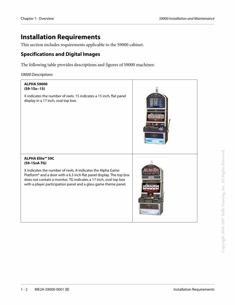
The following table provides descriptions and figures of S9000 machines:
S9000 Descriptions
ALPHA S9000(S9-1Sx--15)
X indicates the number of reels. 15 indicates a 15 inch, flat panel display in a 17 inch, oval top box.
ALPHA Elite™ S9C(S9-1SxA-TG)
X indicates the number of reels. A indicates the Alpha Game Platform® and a door with a 6.3 inch flat panel display. The top box does not contain a monitor. TG indicates a 17 inch, oval top box with a player participation panel and a glass game theme panel.
S9000 Installation and Maintenance Chapter 1: Overview
Installation Requirements MK2A-S9000-0001 [B] 1 - 3
Cop
yrig
ht 2
006-
2007
Bal
ly G
amin
g, In
c. A
ll Ri
ghts
Res
erve
d.
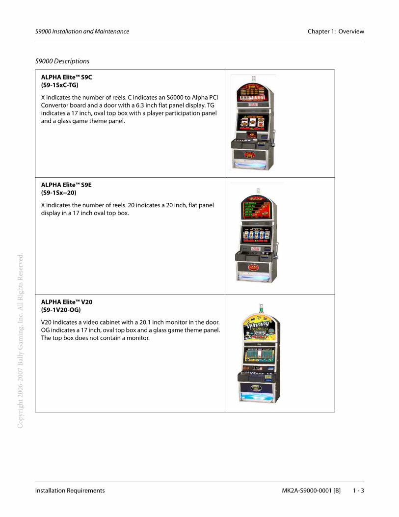
ALPHA Elite™ S9C(S9-1SxC-TG)
X indicates the number of reels. C indicates an S6000 to Alpha PCI Convertor board and a door with a 6.3 inch flat panel display. TG indicates a 17 inch, oval top box with a player participation panel and a glass game theme panel.
ALPHA Elite™ S9E(S9-1Sx--20)
X indicates the number of reels. 20 indicates a 20 inch, flat panel display in a 17 inch oval top box.
ALPHA Elite™ V20(S9-1V20-OG)
V20 indicates a video cabinet with a 20.1 inch monitor in the door. OG indicates a 17 inch, oval top box and a glass game theme panel. The top box does not contain a monitor.
S9000 Descriptions
Chapter 1: Overview S9000 Installation and Maintenance
1 - 4 MK2A-S9000-0001 [B] Installation Requirements
Cop
yrig
ht 2
006-
2007
Bal
ly G
amin
g, In
c. A
ll Ri
ghts
Res
erve
d.
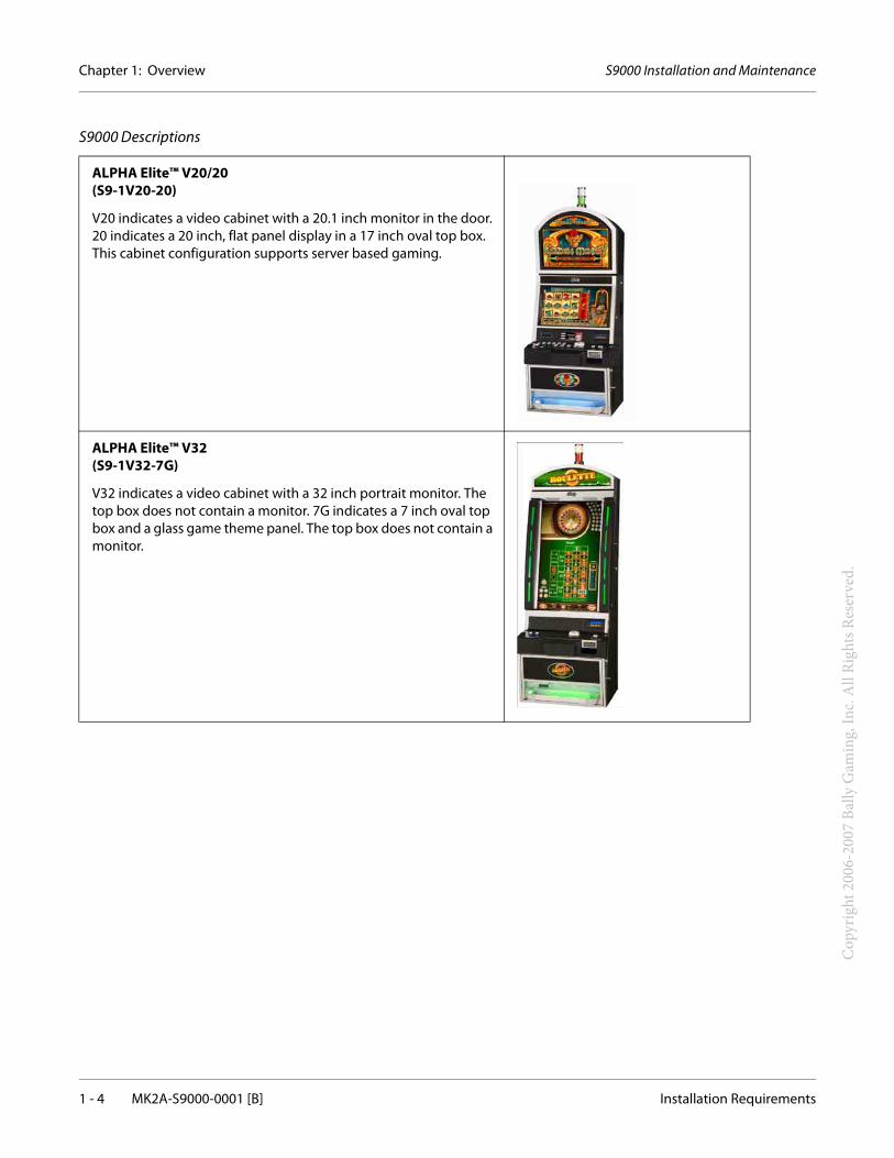
ALPHA Elite™ V20/20(S9-1V20-20)
V20 indicates a video cabinet with a 20.1 inch monitor in the door. 20 indicates a 20 inch, flat panel display in a 17 inch oval top box. This cabinet configuration supports server based gaming.
ALPHA Elite™ V32(S9-1V32-7G)
V32 indicates a video cabinet with a 32 inch portrait monitor. The top box does not contain a monitor. 7G indicates a 7 inch oval top box and a glass game theme panel. The top box does not contain a monitor.
S9000 Descriptions
S9000 Installation and Maintenance Chapter 1: Overview
Installation Requirements MK2A-S9000-0001 [B] 1 - 5
Cop
yrig
ht 2
006-
2007
Bal
ly G
amin
g, In
c. A
ll Ri
ghts
Res
erve
d.
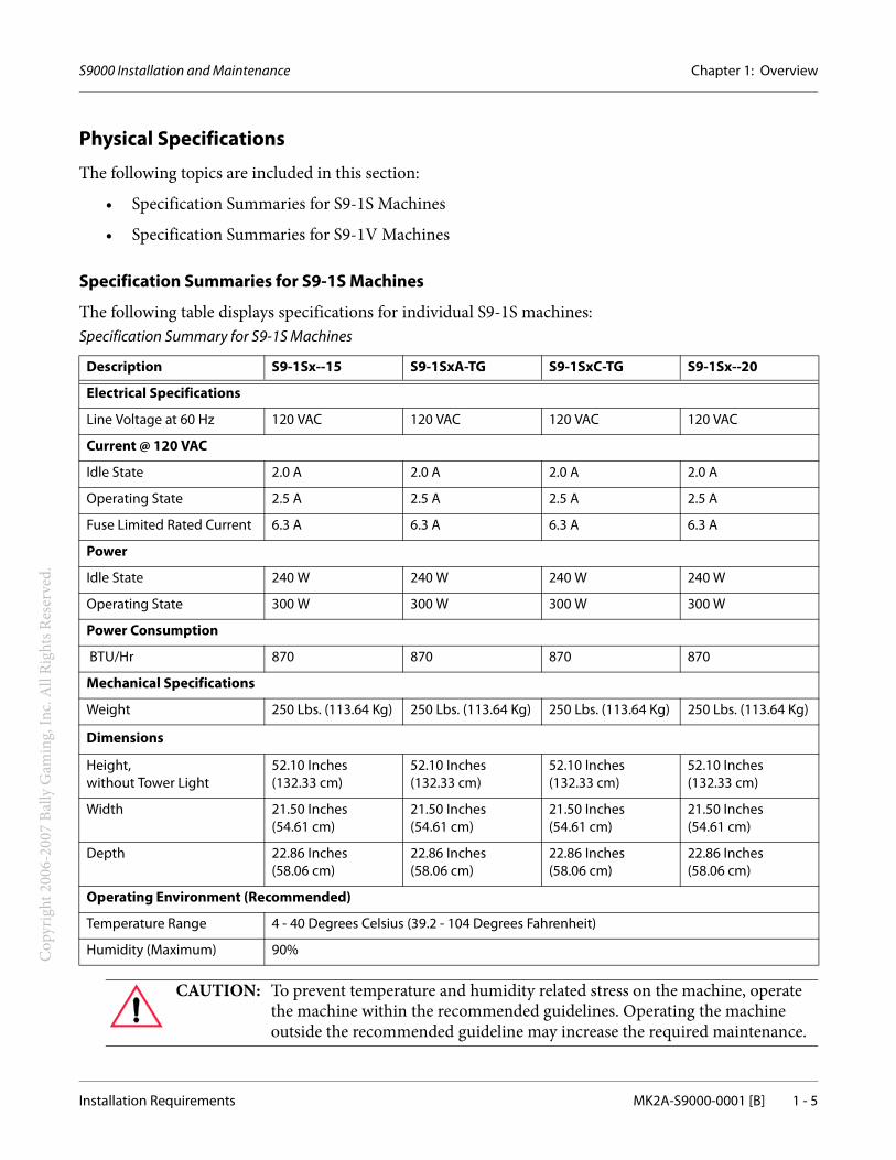
Physical Specifications
The following topics are included in this section:
• Specification Summaries for S9-1S Machines
• Specification Summaries for S9-1V Machines
Specification Summaries for S9-1S Machines
The following table displays specifications for individual S9-1S machines:Specification Summary for S9-1S Machines
Description S9-1Sx--15 S9-1SxA-TG S9-1SxC-TG S9-1Sx--20
Electrical Specifications
Line Voltage at 60 Hz 120 VAC 120 VAC 120 VAC 120 VAC
Current @ 120 VAC
Idle State 2.0 A 2.0 A 2.0 A 2.0 A
Operating State 2.5 A 2.5 A 2.5 A 2.5 A
Fuse Limited Rated Current 6.3 A 6.3 A 6.3 A 6.3 A
Power
Idle State 240 W 240 W 240 W 240 W
Operating State 300 W 300 W 300 W 300 W
Power Consumption
BTU/Hr 870 870 870 870
Mechanical Specifications
Weight 250 Lbs. (113.64 Kg) 250 Lbs. (113.64 Kg) 250 Lbs. (113.64 Kg) 250 Lbs. (113.64 Kg)
Dimensions
Height, without Tower Light
52.10 Inches (132.33 cm)
52.10 Inches (132.33 cm)
52.10 Inches (132.33 cm)
52.10 Inches (132.33 cm)
Width 21.50 Inches (54.61 cm)
21.50 Inches (54.61 cm)
21.50 Inches (54.61 cm)
21.50 Inches (54.61 cm)
Depth 22.86 Inches (58.06 cm)
22.86 Inches (58.06 cm)
22.86 Inches (58.06 cm)
22.86 Inches (58.06 cm)
Operating Environment (Recommended)
Temperature Range 4 - 40 Degrees Celsius (39.2 - 104 Degrees Fahrenheit)
Humidity (Maximum) 90%
CAUTION: To prevent temperature and humidity related stress on the machine, operate the machine within the recommended guidelines. Operating the machine outside the recommended guideline may increase the required maintenance.
Chapter 1: Overview S9000 Installation and Maintenance
1 - 6 MK2A-S9000-0001 [B] Installation Requirements
Cop
yrig
ht 2
006-
2007
Bal
ly G
amin
g, In
c. A
ll Ri
ghts
Res
erve
d.
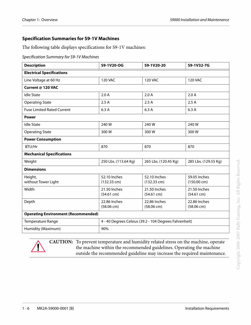
Specification Summaries for S9-1V Machines
The following table displays specifications for S9-1V machines:
Specification Summary for S9-1V Machines
Description S9-1V20-OG S9-1V20-20 S9-1V32-7G
Electrical Specifications
Line Voltage at 60 Hz 120 VAC 120 VAC 120 VAC
Current @ 120 VAC
Idle State 2.0 A 2.0 A 2.0 A
Operating State 2.5 A 2.5 A 2.5 A
Fuse Limited Rated Current 6.3 A 6.3 A 6.3 A
Power
Idle State 240 W 240 W 240 W
Operating State 300 W 300 W 300 W
Power Consumption
BTU/Hr 870 870 870
Mechanical Specifications
Weight 250 Lbs. (113.64 Kg) 265 Lbs. (120.45 Kg) 285 Lbs. (129.55 Kg)
Dimensions
Height, without Tower Light
52.10 Inches (132.33 cm)
52.10 Inches (132.33 cm)
59.05 Inches (150.00 cm)
Width 21.50 Inches (54.61 cm)
21.50 Inches (54.61 cm)
21.50 Inches (54.61 cm)
Depth 22.86 Inches (58.06 cm)
22.86 Inches (58.06 cm)
22.86 Inches (58.06 cm)
Operating Environment (Recommended)
Temperature Range 4 - 40 Degrees Celsius (39.2 - 104 Degrees Fahrenheit)
Humidity (Maximum) 90%
CAUTION: To prevent temperature and humidity related stress on the machine, operate the machine within the recommended guidelines. Operating the machine outside the recommended guideline may increase the required maintenance.
S9000 Installation and Maintenance Chapter 1: Overview
Installation Requirements MK2A-S9000-0001 [B] 1 - 7
Cop
yrig
ht 2
006-
2007
Bal
ly G
amin
g, In
c. A
ll Ri
ghts
Res
erve
d.
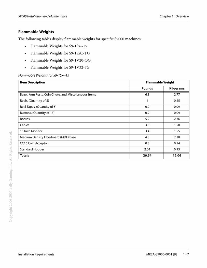
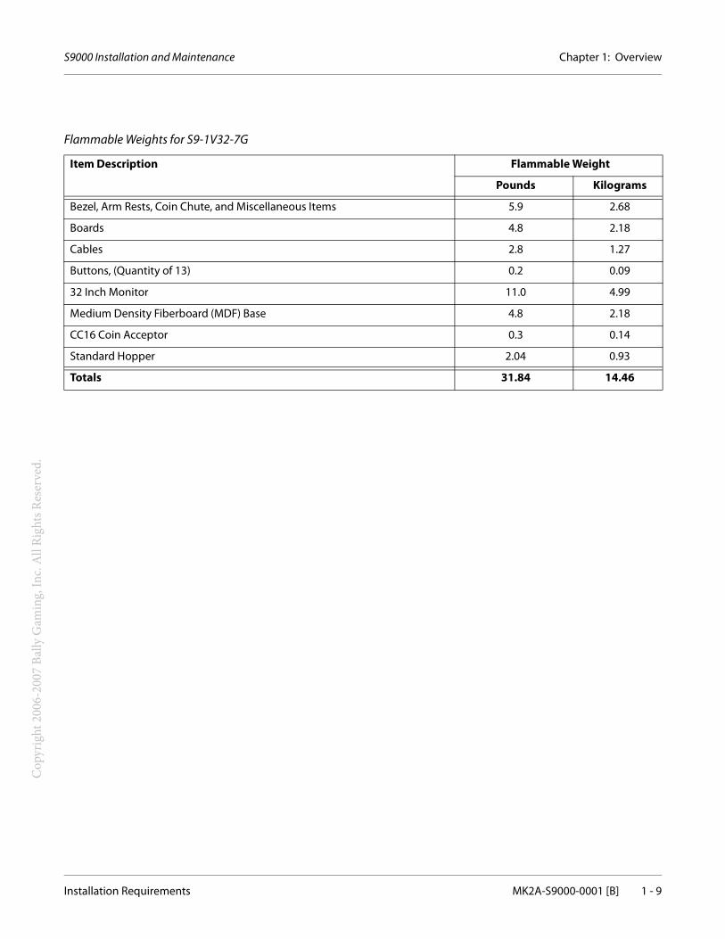
Flammable Weights
The following tables display flammable weights for specific S9000 machines:
• Flammable Weights for S9-1Sx--15
• Flammable Weights for S9-1SxC-TG
• Flammable Weights for S9-1V20-OG
• Flammable Weights for S9-1V32-7G
Flammable Weights for S9-1Sx--15
Item Description Flammable Weight
Pounds Kilograms
Bezel, Arm Rests, Coin Chute, and Miscellaneous Items 6.1 2.77
Reels, (Quantity of 5) 1 0.45
Reel Tapes, (Quantity of 5) 0.2 0.09
Buttons, (Quantity of 13) 0.2 0.09
Boards 5.2 2.36
Cables 3.3 1.50
15 Inch Monitor 3.4 1.55
Medium Density Fiberboard (MDF) Base 4.8 2.18
CC16 Coin Acceptor 0.3 0.14
Standard Hopper 2.04 0.93
Totals 26.54 12.06
Chapter 1: Overview S9000 Installation and Maintenance
1 - 8 MK2A-S9000-0001 [B] Installation Requirements
Cop
yrig
ht 2
006-
2007
Bal
ly G
amin
g, In
c. A
ll Ri
ghts
Res
erve
d.
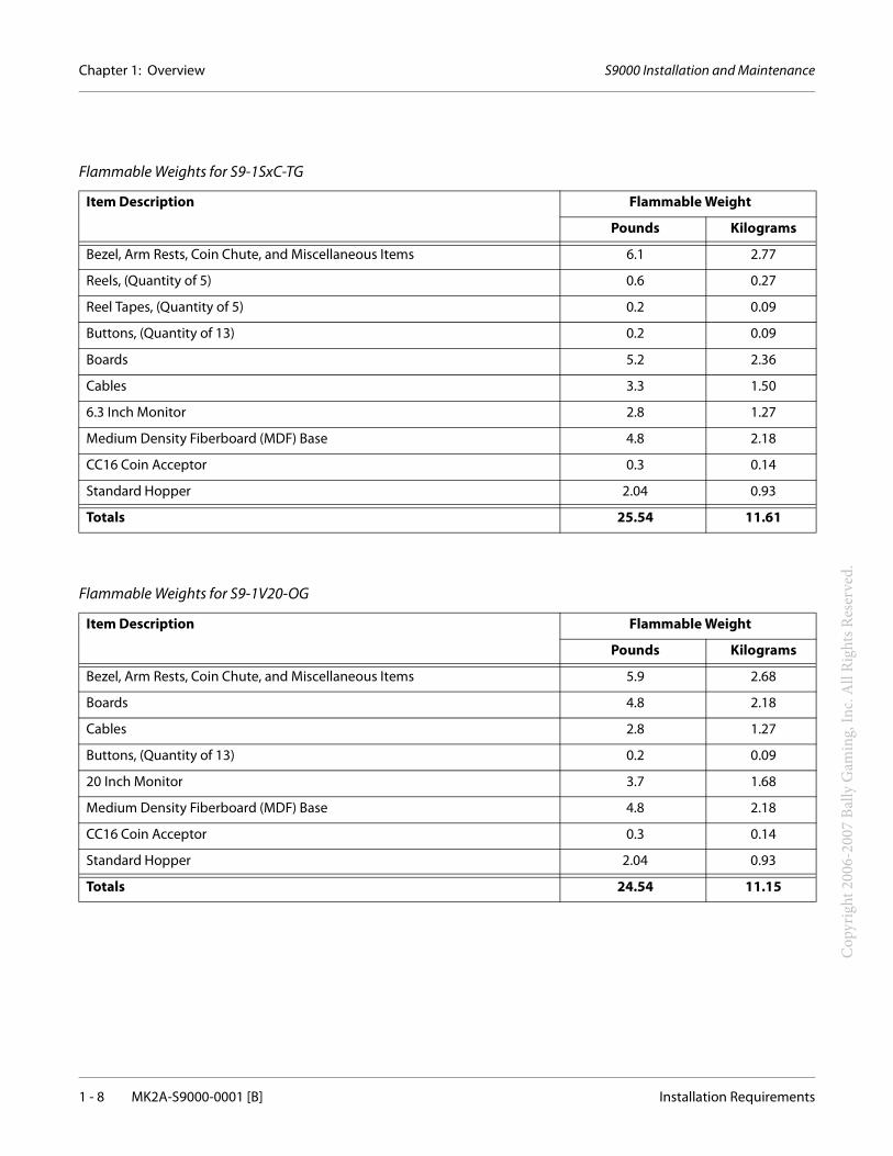
Flammable Weights for S9-1SxC-TG
Item Description Flammable Weight
Pounds Kilograms
Bezel, Arm Rests, Coin Chute, and Miscellaneous Items 6.1 2.77
Reels, (Quantity of 5) 0.6 0.27
Reel Tapes, (Quantity of 5) 0.2 0.09
Buttons, (Quantity of 13) 0.2 0.09
Boards 5.2 2.36
Cables 3.3 1.50
6.3 Inch Monitor 2.8 1.27
Medium Density Fiberboard (MDF) Base 4.8 2.18
CC16 Coin Acceptor 0.3 0.14
Standard Hopper 2.04 0.93
Totals 25.54 11.61
Flammable Weights for S9-1V20-OG
Item Description Flammable Weight
Pounds Kilograms
Bezel, Arm Rests, Coin Chute, and Miscellaneous Items 5.9 2.68
Boards 4.8 2.18
Cables 2.8 1.27
Buttons, (Quantity of 13) 0.2 0.09
20 Inch Monitor 3.7 1.68
Medium Density Fiberboard (MDF) Base 4.8 2.18
CC16 Coin Acceptor 0.3 0.14
Standard Hopper 2.04 0.93
Totals 24.54 11.15
S9000 Installation and Maintenance Chapter 1: Overview
Installation Requirements MK2A-S9000-0001 [B] 1 - 9
Cop
yrig
ht 2
006-
2007
Bal
ly G
amin
g, In
c. A
ll Ri
ghts
Res
erve
d.
Flammable Weights for S9-1V32-7G
Item Description Flammable Weight
Pounds Kilograms
Bezel, Arm Rests, Coin Chute, and Miscellaneous Items 5.9 2.68
Boards 4.8 2.18
Cables 2.8 1.27
Buttons, (Quantity of 13) 0.2 0.09
32 Inch Monitor 11.0 4.99
Medium Density Fiberboard (MDF) Base 4.8 2.18
CC16 Coin Acceptor 0.3 0.14
Standard Hopper 2.04 0.93
Totals 31.84 14.46
Chapter 1: Overview S9000 Installation and Maintenance
1 - 10 MK2A-S9000-0001 [B] Installation Requirements
Cop
yrig
ht 2
006-
2007
Bal
ly G
amin
g, In
c. A
ll Ri
ghts
Res
erve
d.
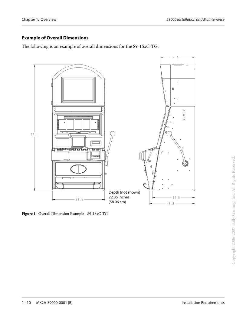
Example of Overall Dimensions
The following is an example of overall dimensions for the S9-1SxC-TG:
Figure 1: Overall Dimension Example - S9-1SxC-TG
Depth (not shown)22.86 Inches (58.06 cm)
S9000 Installation and Maintenance Chapter 1: Overview
Installation Requirements MK2A-S9000-0001 [B] 1 - 11
Cop
yrig
ht 2
006-
2007
Bal
ly G
amin
g, In
c. A
ll Ri
ghts
Res
erve
d.
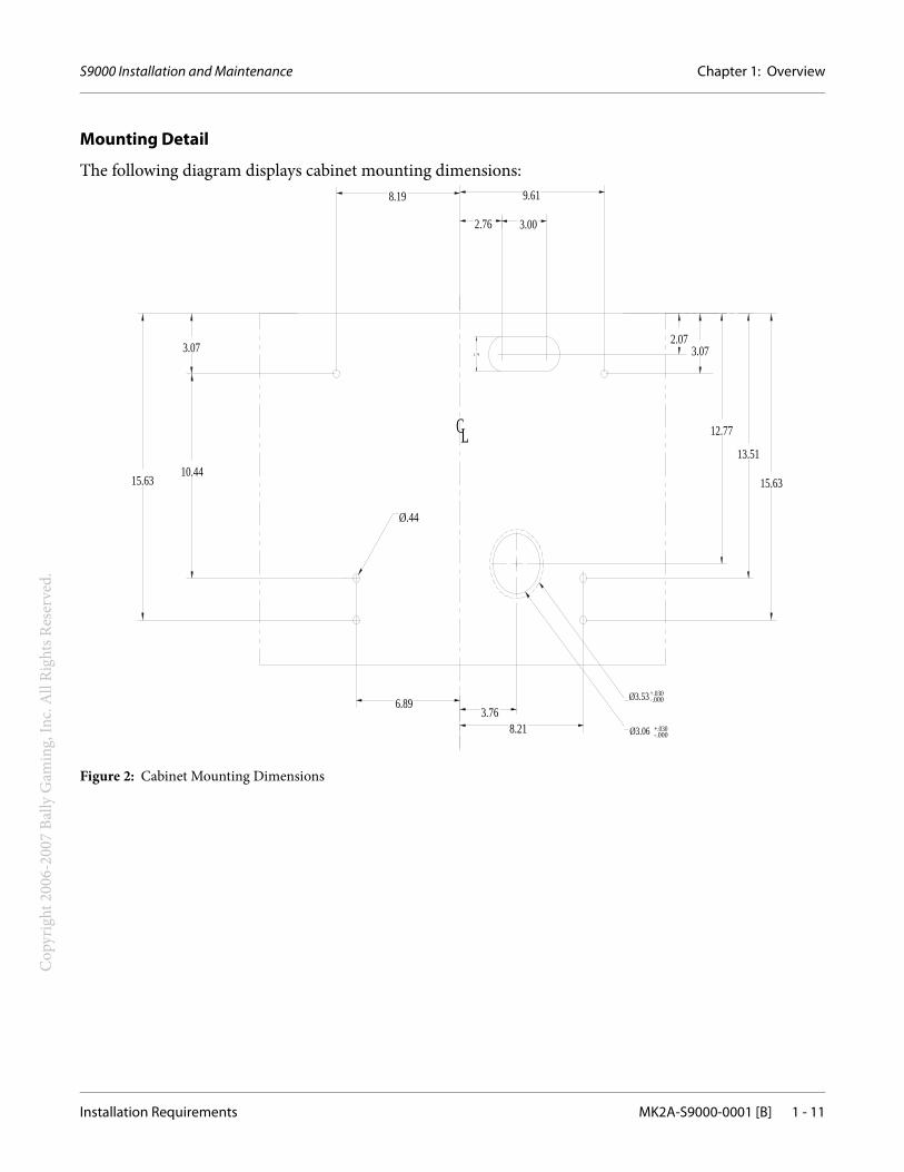
Mounting Detail
The following diagram displays cabinet mounting dimensions:
Figure 2: Cabinet Mounting Dimensions
2.76
3.766.89
Ø.44
15.6310.44
3.07
LC
1.76
8.19
8.21
Ø3.53-.000+.030
13.51
12.77
2.073.07
9.61
3.00
15.63
Ø3.06 -.000+.030
Chapter 1: Overview S9000 Installation and Maintenance
1 - 12 MK2A-S9000-0001 [B] Required Parts
Cop
yrig
ht 2
006-
2007
Bal
ly G
amin
g, In
c. A
ll Ri
ghts
Res
erve
d.
Required PartsThis installation may require the following additional parts:
• Locks (quantity 5 to 7, depending on your machine configuration).
• Category 5 network cables, for linking game controllers, if required (quantity and length depending on your machine configuration and your floor plan).
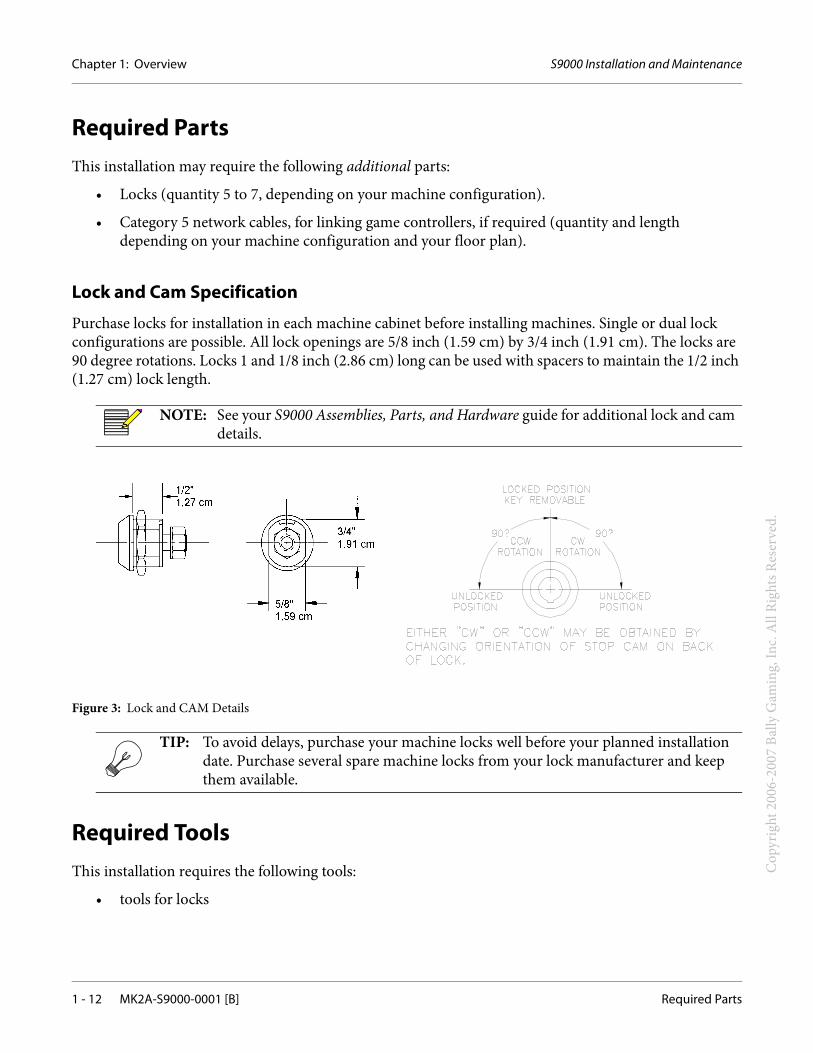
Lock and Cam Specification
Purchase locks for installation in each machine cabinet before installing machines. Single or dual lock configurations are possible. All lock openings are 5/8 inch (1.59 cm) by 3/4 inch (1.91 cm). The locks are 90 degree rotations. Locks 1 and 1/8 inch (2.86 cm) long can be used with spacers to maintain the 1/2 inch (1.27 cm) lock length.
Figure 3: Lock and CAM Details
Required ToolsThis installation requires the following tools:
• tools for locks
NOTE: See your S9000 Assemblies, Parts, and Hardware guide for additional lock and cam details.
TIP: To avoid delays, purchase your machine locks well before your planned installation date. Purchase several spare machine locks from your lock manufacturer and keep them available.
S9000 Installation and Maintenance Chapter 1: Overview
Installation Checklist MK2A-S9000-0001 [B] 1 - 13
Cop
yrig
ht 2
006-
2007
Bal
ly G
amin
g, In
c. A
ll Ri
ghts
Res
erve
d.
Installation ChecklistUse the following checklist to prepare to install the machine:
Pre-Installation Steps
Complete the following steps before installing the machine:
Purchase, assemble, and install power and network cabling for the desired floor plan.
Purchase and receive locks.
Installation Steps
Complete the following steps to install the machine. See Installation Instructions on page 2 - 1 for details.
Unpacking and Inspecting the Machine
Installing the Machine
Installing Locks
Powering On the Machine
Chapter 1: Overview S9000 Installation and Maintenance
1 - 14 MK2A-S9000-0001 [B] Installation Checklist
Cop
yrig
ht 2
006-
2007
Bal
ly G
amin
g, In
c. A
ll Ri
ghts
Res
erve
d.
MK2A-S9000-0001 [B] 2 - 1
S9000 Installation and Maintenance
Cop
yrig
ht 2
006-
2007
Bal
ly G
amin
g, In
c. A
ll Ri
ghts
Res
erve
d.
Chapter 2
Installation
Installation InstructionsThis section includes the following installation instructions:
• Unpacking and Inspecting the Machine
• Installing the Machine
Installing Locks
Powering On the Machine
Chapter 2: Installation S9000 Installation and Maintenance
2 - 2 MK2A-S9000-0001 [B] Installation Instructions
Cop
yrig
ht 2
006-
2007
Bal
ly G
amin
g, In
c. A
ll Ri
ghts
Res
erve
d.
Unpacking and Inspecting the Machine
Use the following instructions to unpack and inspect the machine:
STEP 1. Remove any plastic packaging.
STEP 2. Verify that the serial numbers on the cabinet match the shipping documents associated with the installation.
STEP 3. Inspect the cabinet for any shipping damage, such as broken glass, dents, or scratches.
STEP 4. Inspect the corners of the glass panels for shipping damage.
STEP 5. Unpack and remove all loose parts from any boxes or bags containing cables, lock cams, and mounting hardware.
STEP 6. Remove all plastic or paper packing materials from any interior assemblies, such as a printer.
STEP 7. Inspect the interior cables and ensure they are firmly connected.
STEP 8. Inspect the circuit board assemblies and CompactFlash for loose connections and ensure they are firmly attached.
STEP 9. If there is damage to the machine or there are any missing parts, then contact your Bally Technologies Distributor or Customer Service Representative for Return Merchandise Authorization (RMA) information.
TIP: To prevent damage to the front of the machine, remove the packaging while standing at the back of the machine. If any marks are made on the back of the cabinet while opening the packaging, then use shoe polish to minimize the appearance of marks.
CAUTION: Serial numbers on the cabinet must match the shipping documents that are associated with the installation. Never remove serial numbers from any Bally equipment.
TIP: During shipping, cables may become disconnected and circuit boards may become unseated. Ensure they are firmly attached before proceeding.
S9000 Installation and Maintenance Chapter 2: Installation
Installation Instructions MK2A-S9000-0001 [B] 2 - 3
Cop
yrig
ht 2
006-
2007
Bal
ly G
amin
g, In
c. A
ll Ri
ghts
Res
erve
d.
Installing the Machine
Use the following instructions to move and connect the machine:
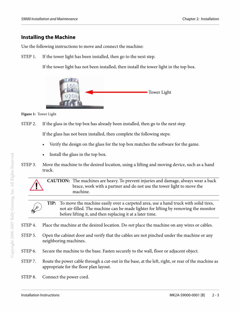
STEP 1. If the tower light has been installed, then go to the next step.
If the tower light has not been installed, then install the tower light in the top box.
Figure 1: Tower Light
STEP 2. If the glass in the top box has already been installed, then go to the next step.
If the glass has not been installed, then complete the following steps:
• Verify the design on the glass for the top box matches the software for the game.
• Install the glass in the top box.
STEP 3. Move the machine to the desired location, using a lifting and moving device, such as a hand truck.
STEP 4. Place the machine at the desired location. Do not place the machine on any wires or cables.
STEP 5. Open the cabinet door and verify that the cables are not pinched under the machine or any neighboring machines.
STEP 6. Secure the machine to the base. Fasten securely to the wall, floor or adjacent object.
STEP 7. Route the power cable through a cut-out in the base, at the left, right, or rear of the machine as appropriate for the floor plan layout.
STEP 8. Connect the power cord.
CAUTION: The machines are heavy. To prevent injuries and damage, always wear a back brace, work with a partner and do not use the tower light to move the machine.
TIP: To move the machine easily over a carpeted area, use a hand truck with solid tires, not air-filled. The machine can be made lighter for lifting by removing the monitor before lifting it, and then replacing it at a later time.
Tower Light
Chapter 2: Installation S9000 Installation and Maintenance
2 - 4 MK2A-S9000-0001 [B] Installation Instructions
Cop
yrig
ht 2
006-
2007
Bal
ly G
amin
g, In
c. A
ll Ri
ghts
Res
erve
d.
Installing Locks
Use the following instructions to install locks on the machine:
STEP 1. If the door, stand, and other high-security locks have already been installed, then go to the next section.
If the door, stand, and other high-security locks have not been installed or if your cabinet contains locks used for shipping purposes only, then order locks from a reliable lock supplier. See S9000 Assemblies, Parts, and Hardware in the S9000 Operator’s Instruction Manual for additional lock cam information.
STEP 2. Use the instructions provided by your lock manufacturer to install locks on the main door, OS chip, main processor unit, and any other appropriate areas on your machine. (Machine configurations may vary.)
TIP: Put the key in the open position to remove the entire lock before removing the nut to disassemble it.
S9000 Installation and Maintenance Chapter 2: Installation
Installation Instructions MK2A-S9000-0001 [B] 2 - 5
Cop
yrig
ht 2
006-
2007
Bal
ly G
amin
g, In
c. A
ll Ri
ghts
Res
erve
d.
Powering On the Machine
Use the following instructions to start the machine:
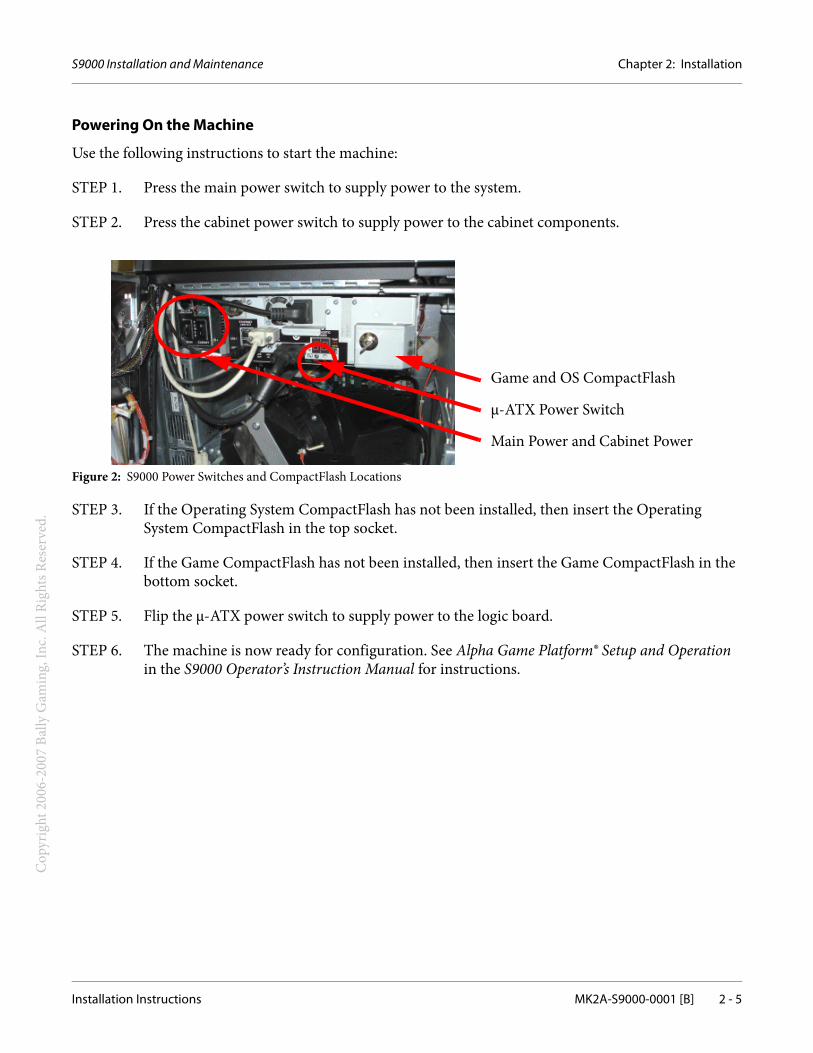
STEP 1. Press the main power switch to supply power to the system.
STEP 2. Press the cabinet power switch to supply power to the cabinet components.
Figure 2: S9000 Power Switches and CompactFlash Locations
STEP 3. If the Operating System CompactFlash has not been installed, then insert the Operating System CompactFlash in the top socket.
STEP 4. If the Game CompactFlash has not been installed, then insert the Game CompactFlash in the bottom socket.
STEP 5. Flip the µ-ATX power switch to supply power to the logic board.
STEP 6. The machine is now ready for configuration. See Alpha Game Platform® Setup and Operation in the S9000 Operator’s Instruction Manual for instructions.
Game and OS CompactFlash
µ-ATX Power Switch
Main Power and Cabinet Power
Chapter 2: Installation S9000 Installation and Maintenance
2 - 6 MK2A-S9000-0001 [B] Installation Instructions
Cop
yrig
ht 2
006-
2007
Bal
ly G
amin
g, In
c. A
ll Ri
ghts
Res
erve
d.
MK2A-S9000-0001 [B] 3 - 1
S9000 Installation and Maintenance
Cop
yrig
ht 2
006-
2007
Bal
ly G
amin
g, In
c. A
ll Ri
ghts
Res
erve
d.
Chapter 3
Relocating the Cabinet
Relocate a MachineUse the following instructions to relocate a machine:
STEP 1. Ensure the new location has appropriate power and network cabling installed.
STEP 2. Flip the µ-ATX power switch off to power off the logic board.
STEP 3. Press the cabinet switch to power off the cabinet components.
STEP 4. Press the main power switch to power off the system.
STEP 5. Unplug and remove the power and network cables.
STEP 6. Place the machine at the desired location. Do not place the machine on any wires or cables.
STEP 7. To remove the machine from service, stop here.To relocate and restart the machine, go to the next step.
STEP 8. Open the cabinet door and verify that no cables are pinched at any location.
STEP 9. Secure the machine to the base.
STEP 10. Connect and route the power and network cables through the cut-out provided at the left, right, or rear of the base as appropriate for the floor plan.
STEP 11. Press the main power switch to supply power to the cabinet.
NOTE: Changes in floor configuration may require rerunning power and Category 5 network cables.
Chapter 3: Relocating the Cabinet S9000 Installation and Maintenance
3 - 2 MK2A-S9000-0001 [B] Relocate a Machine
Cop
yrig
ht 2
006-
2007
Bal
ly G
amin
g, In
c. A
ll Ri
ghts
Res
erve
d.
STEP 12. Press the cabinet power switch to supply power to the cabinet components.
STEP 13. Flip the µ-ATX power switch on to supply power to the logic board.
MK2A-S9000-0001 [B] 4 - 1
S9000 Installation and Maintenance
Cop
yrig
ht 2
006-
2007
Bal
ly G
amin
g, In
c. A
ll Ri
ghts
Res
erve
d.
Chapter 4
Periodic Maintenance
This section provides periodic maintenance information for all machine models and the following components:
• Cabinet
• Machine Door
• Coin Entry
• Coin Hopper
• Bill Acceptor
• Handle Mechanism
• Reel Drive
• Monitor
• Printer
• Main Processing Unit (MPU)
NOTE: Machine configurations may vary.
Chapter 4: Periodic Maintenance S9000 Installation and Maintenance
4 - 2 MK2A-S9000-0001 [B] Periodic Maintenance Schedule
Cop
yrig
ht 2
006-
2007
Bal
ly G
amin
g, In
c. A
ll Ri
ghts
Res
erve
d.
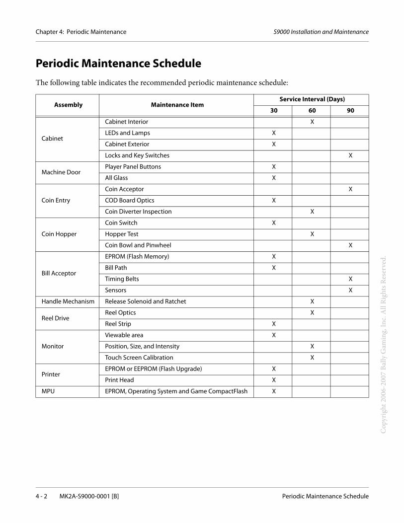
Periodic Maintenance ScheduleThe following table indicates the recommended periodic maintenance schedule:
Assembly Maintenance ItemService Interval (Days)
30 60 90
Cabinet
Cabinet Interior X
LEDs and Lamps X
Cabinet Exterior X
Locks and Key Switches X
Machine DoorPlayer Panel Buttons X
All Glass X
Coin Entry
Coin Acceptor X
COD Board Optics X
Coin Diverter Inspection X
Coin Hopper
Coin Switch X
Hopper Test X
Coin Bowl and Pinwheel X
Bill Acceptor
EPROM (Flash Memory) X
Bill Path X
Timing Belts X
Sensors X
Handle Mechanism Release Solenoid and Ratchet X
Reel DriveReel Optics X
Reel Strip X
Monitor
Viewable area X
Position, Size, and Intensity X
Touch Screen Calibration X
PrinterEPROM or EEPROM (Flash Upgrade) X
Print Head X
MPU EPROM, Operating System and Game CompactFlash X
S9000 Installation and Maintenance Chapter 4: Periodic Maintenance
Cabinet MK2A-S9000-0001 [B] 4 - 3
Cop
yrig
ht 2
006-
2007
Bal
ly G
amin
g, In
c. A
ll Ri
ghts
Res
erve
d.
CabinetUse the following instructions to maintain the cabinet components:
Cabinet Interior
• Vacuum the inside of the cabinet.
• Remove all dust and debris from the coin chutes.
• Remove loose coins to keep them from shorting electrical connections.
• Inspect the cabinet wiring for pinched or frayed wires.
• Confirm that the mounting hardware fully secures the cabinet to the stand.
• Inspect the power cord for signs of overheating.
LEDs and Lamps
• Replace any burned out LEDs or lamps. Faulty starters may cause flickering fluorescents. All fluorescents illuminate when switching on the machine power.
• Inspect ballasts for overheating.
• Locate burned out button LEDs and feature lamps by playing the machine or by activating the Output Test as described in the Alpha Game Platform® Setup and Operation guide.
Cabinet Exterior
The laminate or powder coat exterior of the cabinet requires little maintenance except for occasional dusting. Avoid abrasive cleansers.
Locks and Key Switches
• Check connections of Key Switches for loose or frayed wires.
• Add a small amount of graphite if the key does not turn easily.
• Check that all lock hardware is secure, yet allowing the lock to work smoothly.
Chapter 4: Periodic Maintenance S9000 Installation and Maintenance
4 - 4 MK2A-S9000-0001 [B] Machine Door
Cop
yrig
ht 2
006-
2007
Bal
ly G
amin
g, In
c. A
ll Ri
ghts
Res
erve
d.
Machine DoorUse the following instructions to maintain the machine door components:
Player Panel Buttons
Use a dry, lint-free cloth to clean the buttons. If a cleaning solution is necessary, use a mild glass cleaner. Avoid abrasive cleansers.
All Glass
Use a dry, lint-free cloth to remove the dust from the glass. Use a mild glass cleaner if necessary. Avoid abrasive cleansers or anything that will damage the protective laminate on the inside of the Display Glass and Feature Glass. Replace faded decals.
S9000 Installation and Maintenance Chapter 4: Periodic Maintenance
Coin Entry MK2A-S9000-0001 [B] 4 - 5
Cop
yrig
ht 2
006-
2007
Bal
ly G
amin
g, In
c. A
ll Ri
ghts
Res
erve
d.
Coin EntryUse the following instructions to maintain the coin entry components:
Coin Acceptor
• Disassemble and clean to remove metal coin fragments.
• Adjust and calibrate according to the manufacturer specifications.
• Inspect connections for frayed or broken wires.
COD Board Optics
The Coin Optic Decoder Board uses an infrared emitter and detector to monitor coins. The emitter and detector are on the same side of the COD board. The emitter shines through the assembly and reflects back to the detector using a prism. Use a lint-free cloth to clean the prism. Check the prism bracket to ensure that the prism is secure.
Coin Diverter Inspection
With power off, the Coin Diverter Assembly should pivot freely. Activate the Output Test as described in the Alpha Game Platform® Setup and Operation guide, to verify operation.
Chapter 4: Periodic Maintenance S9000 Installation and Maintenance
4 - 6 MK2A-S9000-0001 [B] Coin Hopper
Cop
yrig
ht 2
006-
2007
Bal
ly G
amin
g, In
c. A
ll Ri
ghts
Res
erve
d.
Coin HopperUse the following instructions to maintain the coin hopper components:
Coin Switch
Upright and Bartop machines use optical switches to count coins from the hopper. Use a dry, lint-free cloth to clean the lenses.
Check the adjustment of the micro switch on slant machines.
Hopper Test
Activate the Hopper Test as described in the Alpha Game Platform® Setup and Operation guide. The hopper will dispense 10 coins.
Coin Bowl and Pinwheel
• Remove the coin bowl and pinwheel and clean thoroughly to remove coin metal fragments.
• Inspect the hopper knife for excessive wear. Replace, if necessary.
• Inspect the coin probe for broken or frayed wires.
S9000 Installation and Maintenance Chapter 4: Periodic Maintenance
Bill Acceptor MK2A-S9000-0001 [B] 4 - 7
Cop
yrig
ht 2
006-
2007
Bal
ly G
amin
g, In
c. A
ll Ri
ghts
Res
erve
d.
Bill AcceptorUse the following instructions to maintain the bill acceptor components:
EPROM or EEPROM (Flash Memory)
Verify the EPROM or EEPROM (flash upgrade) version is correct and is the latest revision. For example, there may be a newer version available for the changing currency. Replace, if necessary.
Bill Path
Open the acceptor and transport components. Use a dry lint-free cloth to remove any debris.
Timing Belts
Replace frayed or worn belts.
Sensor
Replace dirty, clouded, or scratched lenses as they may degrade the performance of the acceptor. Clean the sensors with a dry lint-free cloth. If cleaning requires a solvent, then use a weak solution of water and mild dish detergent. Allow the lenses to dry completely before closing the acceptor and transport assembly.
Activate the Bill Acceptor Test as described in the Alpha Game Platform® Setup and Operation guide, to verify operation.
Chapter 4: Periodic Maintenance S9000 Installation and Maintenance
4 - 8 MK2A-S9000-0001 [B] Handle Mechanism
Cop
yrig
ht 2
006-
2007
Bal
ly G
amin
g, In
c. A
ll Ri
ghts
Res
erve
d.
Handle MechanismUse the following instructions to maintain the handle mechanism components:
Release Solenoid and Ratchet
The handle mechanism consists of a ratchet assembly, an optic sensor, a release solenoid, and an arm assembly. Inspect the handle mechanism for proper function and to ensure handle arm is secure.
Press the pseudo coin button to energize the handle release solenoid and allow the handle to move. Pull the handle and check for smooth ratchet operation. The reels should spin when the handle is in the full forward position. Release the handle and ensure it returns and locks into its original upright position.
CAUTION: The handle mechanism is factory lubricated and does not require additional lubrication or adjustment.
S9000 Installation and Maintenance Chapter 4: Periodic Maintenance
Reel Drive MK2A-S9000-0001 [B] 4 - 9
Cop
yrig
ht 2
006-
2007
Bal
ly G
amin
g, In
c. A
ll Ri
ghts
Res
erve
d.
Reel DriveUse the following instructions to maintain the reel drive components:
Reel Optics
Optical sensors monitor the reel positions. Clean the reel optics with a dry lint-free cloth or swab. Dirty reel optics can cause reel movement tilts on some machine configurations.
Reel Strip
Clean each reel strip with a soft cloth moistened with warm water. Use new tape to reattach any reel strips that are showing signs of separation.
Chapter 4: Periodic Maintenance S9000 Installation and Maintenance
4 - 10 MK2A-S9000-0001 [B] Monitor
Cop
yrig
ht 2
006-
2007
Bal
ly G
amin
g, In
c. A
ll Ri
ghts
Res
erve
d.
MonitorUse the following instructions to maintain the monitor components:
Viewable Area
Abrasive or ammonia-based cleaners can damage the material bonding the Micro Touch® touch screen to the monitor. Clean the monitor with an antistatic nonabrasive cloth and a cleaner recommended for laptop computer screens.
Position, Color, and Size
Check for correct horizontal and vertical alignment by ensuring that all text and images are within the borders of the monitor bezel. Use the monitor color and screen size diagnostics as described in the Alpha Game Platform® Setup and Operation guide.
Touch Screen Calibration
Settings for the touch screen will change over time, or with any adjustment made to the monitor. Calibrate the touch screen according to the directions described in the Alpha Game Platform® Setup and Operation guide.
S9000 Installation and Maintenance Chapter 4: Periodic Maintenance
Printer MK2A-S9000-0001 [B] 4 - 11
Cop
yrig
ht 2
006-
2007
Bal
ly G
amin
g, In
c. A
ll Ri
ghts
Res
erve
d.
PrinterUse the following instructions to maintain the printer components:
EPROM or EEPROM (Flash Upgrade)
Verify the firmware, EPROM or EEPROM (flash upgrade) version is correct and is the latest revision. Replace, if necessary.
Print Head
After opening the unit, the ticket path is accessible for cleaning or clearing tickets. Use a soft brush to clean the paper dust from inside the printer and chassis area. Also remove the paper dust from the sensor optics. If streaking on the printed ticket is evident, the thermal print head may need cleaning.
Cleaning cards are available for thermal printers through TransAct Technologies Incorporated or can be purchased direct from Enefco International Ltd. at (888) 578-0141.

Chapter 4: Periodic Maintenance S9000 Installation and Maintenance
4 - 12 MK2A-S9000-0001 [B] Main Processing Unit (MPU)
Cop
yrig
ht 2
006-
2007
Bal
ly G
amin
g, In
c. A
ll Ri
ghts
Res
erve
d.
Main Processing Unit (MPU)Use the following instructions to maintain the MPU components:
EPROM or CompactFlash
Verify the EPROM or CompactFlash (Operating System and Game) software version is correct. Replace, if necessary.
MK2A-S9000-0001 [B] IX - 1
Cop
yrig
ht 2
006-
2007
Bal
ly G
amin
g, In
c. A
ll Ri
ghts
Res
erve
d.S9000 Installation and Maintenance
Index
Symbols
µ-ATX 2-5, 3-1
B
Bally Technologies Distributor 2-2bill acceptor component maintenance 4-7broken glass 2-2
C
cabinet component maintenancedoor switch optic 4-3
cabinet power switch 3-1cables 2-2cams
lock 2-2category 5 network cables 1-12, 3-1checklist 1-13circuit board assemblies 2-2coin entry component maintenance 4-5coin hopper component maintenance 4-6CompactFlash 2-2, 4-12
D
dents 2-2
dimensions 1-5, 1-6dual lock configuration 1-12
E
EEPROM 4-7, 4-11EPROM 4-7, 4-11, 4-12
F
flammable weight 1-8, 1-9flash upgrade 4-7, 4-11
G
glass 2-3glass panels 2-2
H
hand truck 2-3handle mechanism component maintenance 4-8
I
inspecting the machine 1-13, 2-2
Index S9000 Installation and Maintenance
IX - 2 MK2A-S9000-0001 [B]
Cop
yrig
ht 2
006-
2007
Bal
ly G
amin
g, In
c. A
ll Ri
ghts
Res
erve
d.
installation 1-13checklist 1-13instructions 2-1locks 1-13machine 1-13pre-installation 1-13
L
lock 1-12, 2-4cams 2-2dual lock configuration 1-12installation 1-13openings 1-12single lock configuration 1-12specification, locks and cams 1-12
M
machine doorcomponent maintenance 4-4
main door 2-4main power switch 3-1Main Processing Unit (MPU) component maintenance 4-12main processor unit 2-4maintenance 4-2
bill acceptor components 4-7cabinet components
door switch optic 4-3coin entry components 4-5coin hopper components 4-6handle mechanism components 4-8machine door 4-4monitor components 4-10MPU components 4-12printer components 4-11reel drive components 4-9schedule 4-2
monitor 2-3monitor component maintenance 4-10mounting hardware 2-2moving the machine 3-1
O
OS chip 2-4
P
power cable 2-3, 3-1power switch
cabinet 2-5, 3-1logic board 2-5main 2-5, 3-1
powering off the machine 3-1powering on the machine 1-13pre-installation 1-13printer 2-2printer component maintenance 4-11
R
reel drive component maintenance 4-9relocating the cabinet 3-1required tools 1-12Return Merchandise Authorization (RMA) 2-2
S
scratches 2-2serial numbers 2-2service interval 4-2shipping damage 2-2shipping documents 2-2single lock configuration 1-12software 2-3spacers 1-12
T
top box 2-3tower light 2-3
S9000 Installation and Maintenance Index
MK2A-S9000-0001 [B] IX - 3
Cop
yrig
ht 2
006-
2007
Bal
ly G
amin
g, In
c. A
ll Ri
ghts
Res
erve
d.
U
unpacking the machine 1-13, 2-2
W
weightflammable weight 1-8, 1-9
Index S9000 Installation and Maintenance
IX - 4 MK2A-S9000-0001 [B]
Cop
yrig
ht 2
006-
2007
Bal
ly G
amin
g, In
c. A
ll Ri
ghts
Res
erve
d.