Embed Size (px)
Citation preview
Manual
HoTT GPS Module GPS / Vario Modul Alpha
S8437 EN

2 - 24 S8437_jh_V1
Index
3- 24S8437_jh_V1
Introduction ................................................................................................................4
Service centre .............................................................................................................4
Intended use .............................................................................................................5
Package content .........................................................................................................5
Symbol description .....................................................................................................6
Safety notes ................................................................................................................6
Installation in the model ............................................................................................7
Start up .......................................................................................................................8
Operation.....................................................................................................................8
Operation with the SMART-BOX ........................................................ 9
GPS menu (GPS SENSOR) ...........................................................................................9
Programming - Setting the alarm thresholds .........................................................11
Factory Set ...................................................................................... 13
Warning Time .................................................................................. 13
Repeat Time .................................................................................... 13
Signal Tone ...................................................................................... 13
Maximum distance (Page 2) ............................................................ 14
Minimum speed (Page 3) ................................................................. 14
Minimum altitude (Page 5) ............................................................... 15
Maximum altitude (Page 6) .............................................................. 15
Sink rate per second (Page 7).......................................................... 15
Sink rate per 3 seconds (Page 8) ..................................................... 15
Climb rate per second (Page 9) ................................................ 16
Climb rate per 3 seconds (Page 10)................................................. 16
Setup displays ..........................................................................................................16
Continuous vario ............................................................................. 16
Sensitivity setup .............................................................................. 16
SENSITIVITY (Page 2) ...................................................................... 17
AVERAGE NUMBER (Page 2) .......................................................... 18
Select Unit Type (Page 3) ................................................................. 18
Home Position Setup (Page 4) ......................................................... 18
Telemetry display .....................................................................................................19
Firmware update ......................................................................................................20
Declaration of conformity .........................................................................................22
Notes for environmental protection .........................................................................23
Care and maintenance .............................................................................................23
Warranty certificate ..................................................................................................23
4 - 24 S8437_jh_V1
IntroductionThank you very much for choosing a Graupner GPS VARIO ALPHA MODUL.This Graupner GPS VARIO ALPHA MODUL is extremely versatile. Read this manual carefully to achieve the best results with your Graupner GPS VARIO ALPHA MODUL and first of all to control safely your model. If you experience any trouble during operation, take the instructions to help or ask your dealer or Graupner Service Centre.Due to technical changes, the information may be changed in this manual without prior notice. Be always updated by checking periodically for news on our website, www.graupner.de. This product complies with national and European legal requirements
To maintain this condition and to ensure safe operation, you must read and follow this user manual and the safety notes before using the product!
NOTE
This manual is part of that product. It contains important in-formation concerning operation and handling. Keep these instructions for future reference! Take this into considera-tion when you pass it on to other future owner.
Service centre
Graupner-ZentralserviceGraupner GmbHHenriettenstrasse 96D-73230 Kirchheim / Teck
Servicehotline (+49) (0)7021/722-130Mon - Thu9:15 am - 5:00 pmFri9:15 am - 1:00 pm
For the service centres outside Germany please refer to our web site www.graupner.de
Graupner in InternetGraupner in Internet
5- 24S8437_jh_V1
Intended use The Graupner GPS VARIO ALPHA MODUL allows wireless control of the position and flight altitude so as the visual and audio indica-tions about the climb or sink rate in real time. The Graupner GPS VARIO ALPHA MODUL can be programmed directly with all HoTT transmitters, which have an integrated telemetry menu display.The Graupner GPS VARIO ALPHA MODUL is conceived to be used in remote controlled motors powered by batteries or accumula-tors, any other use is not permitted. For any improper use no guarantee or liability is assumed.Read carefully and entirely this manual before you try to use the product.Graupner constantly works on the development of all products; we reserve the right to change the item, its technology and equipment.
Target groupThe item is not a toy. It is not suitable for children under 14. The use of the Graupner GPS VARIO ALPHA MODUL should be per-formed only by experienced modellers. If you do not have suf-ficient knowledge about dealing with radio-controlled mod-els, please contact an experienced modeller or a model club.
Package contentGPS /VARIO MODUL ALPHA
� Manual
6 - 24
!
S8437_jh_V1
Symbol descriptionAlways follow the information marked with the CAUTION or WARN-ING symbol. The signal word WARNING indicates the potential for serious injury, the signal word CAUTION indicates potential minor injuries.The NOTE indicates important information that should alert you to potential property damage..
Safety notesGeneralThese safety instructions are intended not only to protect the product, but also for your own and other people’s safety. Therefore please read this section very carefully before using the product!.Do not leave the packaging material lying around, this could be a dangerous toy for children.Persons, including children, with reduced physical, sensory or mental capabilities, or lack of experience or knowledge, or not capable to use safely the module must not use the module without supervision or instruction by a responsible person
� The operation of radio controlled models must be learned! If you have never driven such a model, then start extra care-fully and make sure to be familiar with the reactions of the model to the remote control commands. Proceed responsi-bly.
� The module should be used only with HoTT components.
� Pay attention not to overtake the maximum supported volt-age. Risk of fire!
� Protect the module from dust, dirty, humidity and other small parts. Do not expose it to vibrations or to extreme heath or cold. Operating temperature range: -20 to +70°C.
� The use of the module is allowed only in non human-carry-ing models.
� Always use all your HoTT components only with the latest firmware version.
Note: After purchase always check the content for integrity or dam-ages.
!
7- 24S8437_jh_V1
Installation in the modelMount the sensor at an appropriate location in the model. The integrated vario sensor detects changes in air pressure and cal-culates the resulting actual altitude. Therefore, make sure that the sensor is wind-protected in the model and is not located directly in the fl ow of the propeller. Likewise, it must not be mounted on an air-tight place, such in a sealed radio box.
The accuracy of the sensor also varies with alterations in ambi-ent air pressure, e.g. due to sudden changes in weather condi-tions, as well as with changes in air pressure which occur in the course of the day or during an extended flight. It is not uncom-mon for minor fluctuations in air pressure to affect the accuracy of the sensor to the extent of about 10 to 20 m. These inaccu-racies can also be caused by pressure changes inside the fuse-lage itself (e.g. high pressure due to the forced propeller airflow, or air fl owing into the model during a flight).
The GPS module should preferably be mounted under the can-opy of the model to receive the data from the GPS satellites without difficulty. The installation in wood or plastic fuselage is no problem, not possible is the installation in carbon fibre fuse-lage (CFRP), because they shield the GPS signal too much and do not allow reliable operation. The best way to fix the GPS-MOD-ULE with the label facing up with the mounting tabs or double sided tape at an appropriate location in the model is as high up in the fuselage as possible, without any “obstacles” - such as wiring - located over the module, leaves as large an unob-structed angle as possible above the module, so that it can also pick up satellites which are not positioned directly above the model.
By its nature the GPS module can only measure the model’s speed accurately when it is flying level over the ground. Fast dives, steep turns and aerobatics cause rapid changes in the angle of the GPS aerial which can cause reception failures on the one hand, or reception of signals from different GPS satel-lites on the other, either of which can lead to erroneous meas-urements. If you wish to obtain accurate speed measurements, all you need to do normally is to fl y the aircraft level for a period of about one second. However, it can take longer than one sec-ond to pick up an unambiguous signal, i.e. to obtain an accurate measurement, if the model is particularly fast, and especially if the machine makes a rapid transition from vertical to level flight.
8 - 24 S8437_jh_V1
Start upConnect the GPS MODULE with the socket marked „T“ of the receiver. The connector system is polarised, look for the small camfer on the edges. Never use force - the plug should engage easily and fully. The sockets are labelled accordingly: black wire (-), red wire (+) and orange wire (T).
Only for transmitters with SMART-BOX:Install the SMART-BOX at the mounting bracket of the transmit-ter as shown in the figure. Connect the box then the 3-pin lead to the transmitter. Put one end of the cable into the DATA jack on the transmitter and the other into the jack on the right side of the SMART-BOX. The connector system is polarised, look for the small camfer on the edges. Never use force - the plug should engage easily and fully. The sockets are labelled accordingly: black wire (-), red wire (+) and orange wire (T).Note:You can connect the GPS MODULE instead of the receiver directly to the jack on the right side of the SMART-BOX. By doing this, the settings will be sent directly to the GPS MODULE (with-out using the radio control system) and the programming is much faster. A power supply for the SMART-BOX is necessary (3.6 - 9 V), inserted on the left side. The connector system is reverse polarised, look for the small camfer on the edges. Do not use force, the plug should click into place easily. This sock-ets is labelled accordingly also. The black wire must be down (-), the red top (+).
OperationThe operation of the GPS-MODULE is similar to the operation of the transmitter. You should also read the manual of your remote control system, especially the chapter „telemetry“. The operation is done in the transmitter menu „Telemetry“ under the display SETTING AND DATA VIEW. The sensor displays follow the receiver displays (RX), i.e. the „GPS Sensor“ display follows after the last display servo test (RX SERVO TEST). Please note: the menus can only be selected when the receiver is switched on. When you switch the receiver on, it may take a few seconds before the receiver display becomes active and can be selected symbol appears at the top right corner of the transmitter display (TX).There may be a slight delay in the screen’s response to inputs, since all the settings are transmitted directly to the receiver by wireless means.
9- 24S8437_jh_V1
Operation with the SMART-BOXThe SMART-BOX is operated by the four buttons on the top. Switch with the ESC and ENTER keys between the different dis-plays. With the DEC and INC buttons you can select the param-eters in the display (INC moves the cursor down, DEC up).Switch on the transmitter. On the startup screen appears SET-TING AND DATA VIEW / MODEL SELECT.Move the arrow cursor with the INC or DEC buttons on SET-TING AND DATA VIEW and then press ENTER to display the parameters of the transmitter, receiver and telemetry sensors and / or program it, or select MODEL SELECT to display the telemetry data graphically. In MODEL SELECT display no changes are possible.
After SETTING AND DATA VIEW have chosen, the GPS SEN-SOR display is available. The sensor displays follow the trans-mitter (TX) and receiver (RX) displays, i.e. the GPS display fol-lows after the last display servo test (RX SERVO TEST).
Please note: the menus can only be selected when the receiver is switched on. When you switch the receiver on, it may take a few seconds before the receiver display becomes active and can be selected: > symbol appears at the top right corner of the transmitter display (TX).There may be a slight delay in the screen’s response to inputs using the top buttons, since all the settings are transmitted directly to the receiver by wireless means.
GPS menu (GPS SENSOR)Please note: the labelling of the arrows of the following displays corresponds to the keys on top of the SMART-BOX. This assign-ment is different depending on the remote control system:
SMART-BOX
mx-12/16/20/32 HoTT mc-19/mc-22/mc-24/mx-24 HoTT
ENTER u ENTERESC t CLEARINC scroll: q value: p scroll: push Rotary + P value:
Rotary PDEC scroll: p value: q scroll: push Rotary + Q value:
Rotary QINC+DEC SET push Rotary
The descriptive text describes also primarily the button layout and operation of the SMART-BOX, followed by the buttons of the mx-16 HoTT (No. 33116) as an example in parentheses. Please note that the button layout for example of the HoTT mc-transmitters (No. 4758, 4759) may differ. Read the manual of your remote control system to become familiar with the telem-etry operation.
10 - 24 S8437_jh_V1
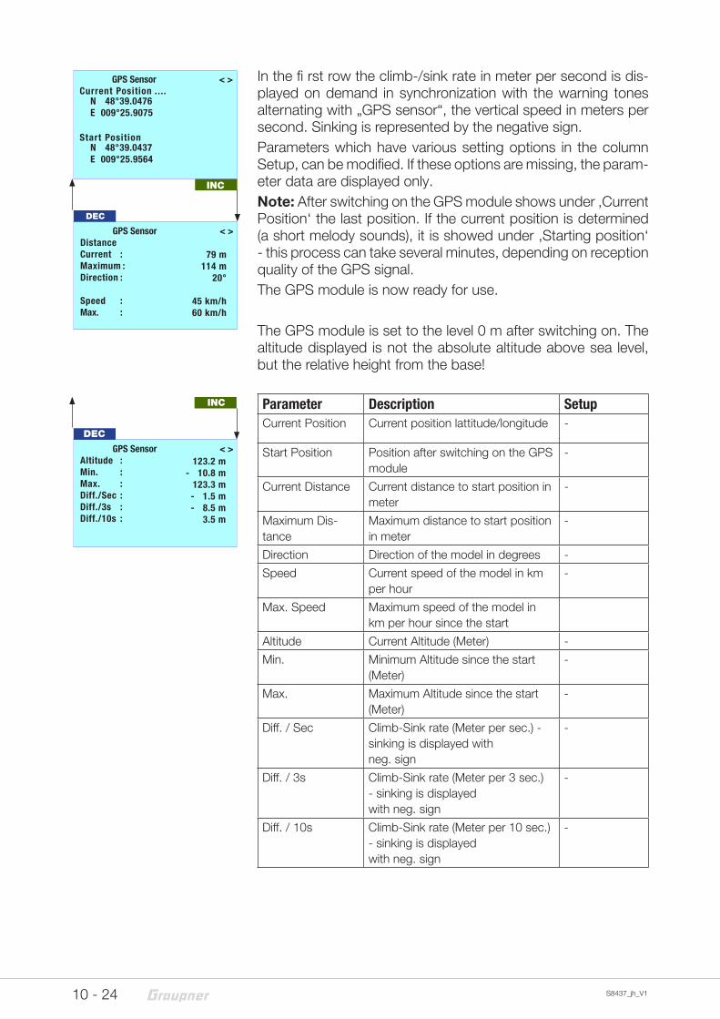
In the fi rst row the climb-/sink rate in meter per second is dis-played on demand in synchronization with the warning tones alternating with „GPS sensor“, the vertical speed in meters per second. Sinking is represented by the negative sign.Parameters which have various setting options in the column Setup, can be modified. If these options are missing, the param-eter data are displayed only.Note: After switching on the GPS module shows under ‚Current Position‘ the last position. If the current position is determined (a short melody sounds), it is showed under ‚Starting position‘ - this process can take several minutes, depending on reception quality of the GPS signal.The GPS module is now ready for use.
The GPS module is set to the level 0 m after switching on. The altitude displayed is not the absolute altitude above sea level, but the relative height from the base!
Parameter Description SetupCurrent Position Current position lattitude/longitude -
Start Position Position after switching on the GPS module
-
Current Distance Current distance to start position in meter
-
Maximum Dis-tance
Maximum distance to start position in meter
-
Direction Direction of the model in degrees -
Speed Current speed of the model in km per hour
-
Max. Speed Maximum speed of the model in km per hour since the start
Altitude Current Altitude (Meter) -
Min. Minimum Altitude since the start (Meter)
-
Max. Maximum Altitude since the start (Meter)
-
Diff. / Sec Climb-Sink rate (Meter per sec.) - sinking is displayed withneg. sign
-
Diff. / 3s Climb-Sink rate (Meter per 3 sec.) - sinking is displayedwith neg. sign
-
Diff. / 10s Climb-Sink rate (Meter per 10 sec.) - sinking is displayedwith neg. sign
-
GPS Sensor < >Distance Current : Maximum : Direction : Speed :Max. :
DEC
79 m114 m
20°
45 km/h60 km/h
INC
GPS Sensor < >Altitude : Min. : Max. : Diff./Sec : Diff./3s : Diff./10s :
123.2 m- 10.8 m
123.3 m- 1.5 m- 8.5 m
3.5 m
DEC
INC
GPS Sensor < >Current Position .... Start Position
N 48°39.0476E 009°25.9075
N 48°39.0437E 009°25.9564
11- 24S8437_jh_V1
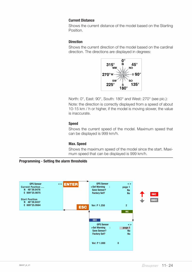
Current DistanceShows the current distance of the model based on the Starting Position.
DirectionShows the current direction of the model based on the cardinal direction. The directions are displayed in degrees:
North: 0°, East: 90°, South: 180° and West: 270° (see pic.):Note: the direction is correctly displayed from a speed of about 10-15 km / h or higher, if the model is moving slower, the value is inaccurate.
SpeedShows the current speed of the model. Maximum speed that can be displayed is 999 km/h.
Max. SpeedShows the maximum speed of the model since the start. Maxi-mum speed that can be displayed is 999 km/h.
Programming - Setting the alarm thresholds
INC
DEC
ENTER
ESC
GPS Sensor < >>Set Warning : Save Sensor? Factory Set?
Ver: P 1.250 2
page 1NoNo
INC
DEC
page 1NoNo
GPS Sensor < >>Set Warning : Save Sensor? Factory Set?
Ver: P 1.000 0
GPS Sensor < >Current Position .... Start Position
N 48°39.0476E 009°25.9075
N 48°39.0437E 009°25.9564
12 - 24 S8437_jh_V1
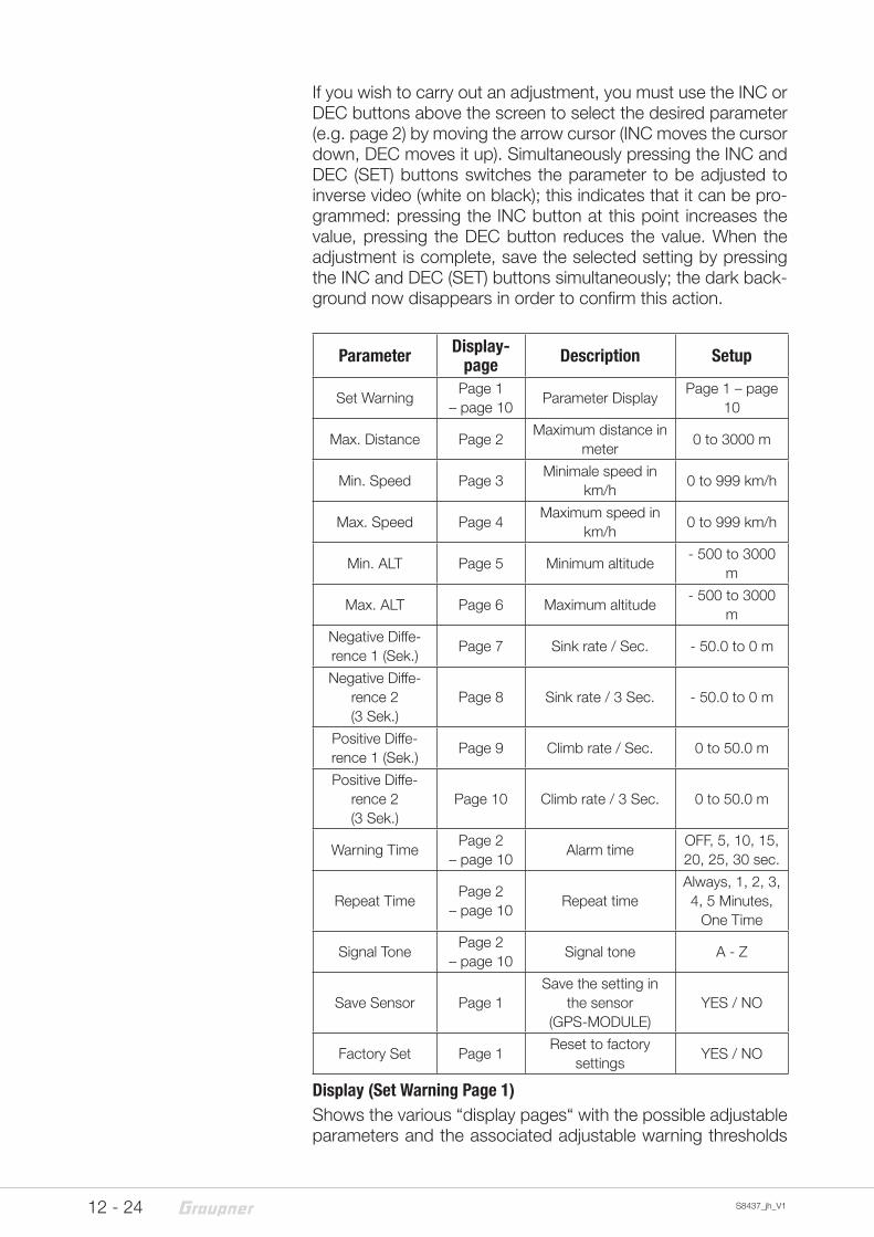
If you wish to carry out an adjustment, you must use the INC or DEC buttons above the screen to select the desired parameter (e.g. page 2) by moving the arrow cursor (INC moves the cursor down, DEC moves it up). Simultaneously pressing the INC and DEC (SET) buttons switches the parameter to be adjusted to inverse video (white on black); this indicates that it can be pro-grammed: pressing the INC button at this point increases the value, pressing the DEC button reduces the value. When the adjustment is complete, save the selected setting by pressing the INC and DEC (SET) buttons simultaneously; the dark back-ground now disappears in order to confirm this action.
Parameter Display-page Description Setup
Set WarningPage 1
– page 10Parameter Display
Page 1 – page 10
Max. Distance Page 2Maximum distance in
meter0 to 3000 m
Min. Speed Page 3Minimale speed in
km/h0 to 999 km/h
Max. Speed Page 4Maximum speed in
km/h0 to 999 km/h
Min. ALT Page 5 Minimum altitude - 500 to 3000
m
Max. ALT Page 6 Maximum altitude - 500 to 3000
m
Negative Diffe-rence 1 (Sek.)
Page 7 Sink rate / Sec. - 50.0 to 0 m
Negative Diffe-rence 2 (3 Sek.)
Page 8 Sink rate / 3 Sec. - 50.0 to 0 m
Positive Diffe-rence 1 (Sek.)
Page 9 Climb rate / Sec. 0 to 50.0 m
Positive Diffe-rence 2(3 Sek.)
Page 10 Climb rate / 3 Sec. 0 to 50.0 m
Warning TimePage 2
– page 10Alarm time
OFF, 5, 10, 15, 20, 25, 30 sec.
Repeat TimePage 2
– page 10Repeat time
Always, 1, 2, 3, 4, 5 Minutes,
One Time
Signal TonePage 2
– page 10Signal tone A - Z
Save Sensor Page 1Save the setting in
the sensor (GPS-MODULE)
YES / NO
Factory Set Page 1Reset to factory
settingsYES / NO
Display (Set Warning Page 1)Shows the various “display pages“ with the possible adjustable parameters and the associated adjustable warning thresholds
13- 24S8437_jh_V1
(page 1, page 2, etc.). To switch between pages, press the INC or DEC key.
Factory SetChoosing “YES“, will reset the settings of the variable module to factory settings.
The following parameters can be set separately for all displays:Warning TimeSets whether and how long the warning signal is activated when reaching a certain value for each display screen.
Repeat TimeSets how often the warning signal is activated when reaching a certain value for each display screen.
Signal ToneSets the signal tone melody. The warning sounds are combined with the warnings on the display and the voice output. The sig-nal tone A-Z are connected to the language selection. Therefore, they may not be changed.
When a warning is activated, the corresponding message (eg. Min. Height) is shown inverted in the first row of the associated display, which then appears alternately with the display GPS SENSOR and the selected Signal Tone A - Z sounds.You can stop the warning at any time by pressing one of the but-tons on the top of the SMARTBOX.
Settings savingTo save the settings in the GPS Module, go back to the menu “page 1 - GPS Sensor“ and select the menu point “Save Sen-sor“. Pushing the “SET“ button switches the parameter to inverse video (white on black) . Push the INC button at this point to increase the value to YES and push the “SET“ to save the selected value, the dark background now disappears in order to confirm this action.If you do not want to save the adjustments, select NO.
14 - 24 S8437_jh_V1
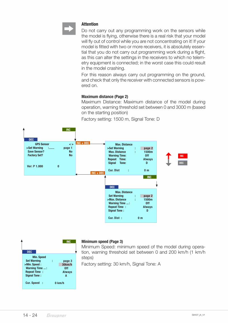
AttentionDo not carry out any programming work on the sensors while the model is flying, otherwise there is a real risk that your model will fly out of control while you are not concentrating on it! If your model is fitted with two or more receivers, it is absolutely essen-tial that you do not carry out programming work during a flight, as this can alter the settings in the receivers to which no telem-etry equipment is connected; in the worst case this could result in the model crashing.For this reason always carry out programming on the ground, and check that only the receiver with connected sensors is pow-ered on.
Maximum distance (Page 2)Maximum Distance: Maximum distance of the model during operation, warning threshold set between 0 and 3000 m (based on the starting position)Factory setting: 1500 m, Signal Tone: D
Minimum speed (Page 3)Minimum Speed: minimum speed of the model during opera-tion, warning threshold set between 0 and 200 km/h (1 km/h steps)Factory setting: 30 km/h, Signal Tone: A
INC
DEC
DECINC + DEC
INC + DEC
INC
Max. Distance >Set Warning : Max. Distance : Warning Time: Repeat Time:Signal Tone:
Cur. Dist :
page 21500m
OffAlways
D 0 m
INC
DEC
Max. Distance Set Warning :>Max. Distance : Warning Time ... : Repeat Time :Signal Tone :
Cur. Dist :
page 21500m
OffAlways
D
0 m
GPS Sensor < >>Set Warning : ....... Save Sensor? Factory Set?
Ver: P 1.000 0
page 1NoNo
DEC
Min. Speed Set Warning :>Min. Speed : Warning Time ... : Repeat Time :Signal Tone :
Cur. Speed :
page 330km/h
OffAlways
A
0 km/h
INC
15- 24S8437_jh_V1
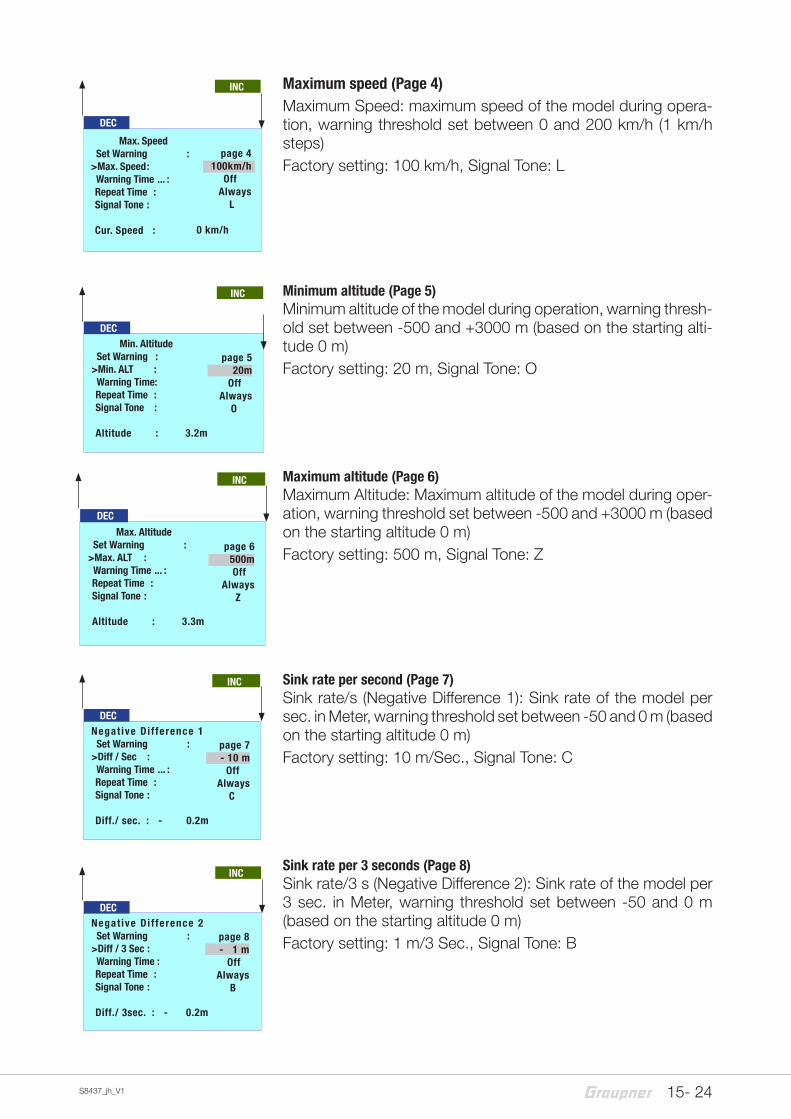
Maximum speed (Page 4)Maximum Speed: maximum speed of the model during opera-tion, warning threshold set between 0 and 200 km/h (1 km/h steps)Factory setting: 100 km/h, Signal Tone: L
Minimum altitude (Page 5)Minimum altitude of the model during operation, warning thresh-old set between -500 and +3000 m (based on the starting alti-tude 0 m)Factory setting: 20 m, Signal Tone: O
Maximum altitude (Page 6)Maximum Altitude: Maximum altitude of the model during oper-ation, warning threshold set between -500 and +3000 m (based on the starting altitude 0 m)Factory setting: 500 m, Signal Tone: Z
Sink rate per second (Page 7)Sink rate/s (Negative Difference 1): Sink rate of the model per sec. in Meter, warning threshold set between -50 and 0 m (based on the starting altitude 0 m)Factory setting: 10 m/Sec., Signal Tone: C
Sink rate per 3 seconds (Page 8)Sink rate/3 s (Negative Difference 2): Sink rate of the model per 3 sec. in Meter, warning threshold set between -50 and 0 m (based on the starting altitude 0 m)Factory setting: 1 m/3 Sec., Signal Tone: B
DEC
Max. Speed Set Warning :>Max. Speed : Warning Time ... : Repeat Time :Signal Tone :
Cur. Speed :
page 4100km/h
OffAlways
L
0 km/h
INC
INC
DEC Min. Altitude Set Warning :>Min. ALT : Warning Time: Repeat Time :Signal Tone :
Altitude : 3.2m
page 520m
OffAlways
O
DEC
Max. Altitude Set Warning :>Max. ALT : Warning Time ... : Repeat Time :Signal Tone :
Altitude : 3.3m
page 6500m
OffAlways
Z
INC
DECNegat ive Di f ference 1 Set Warning :>Diff / Sec : Warning Time ... : Repeat Time :Signal Tone :
Diff./ sec. : - 0.2m
page 7- 10 m
OffAlways
C
INC
DECNegat ive Di f ference 2 Set Warning :>Diff / 3 Sec : Warning Time : Repeat Time :Signal Tone :
Diff./ 3sec. : - 0.2m
page 8- 1 m
OffAlways
B
INC
16 - 24 S8437_jh_V1
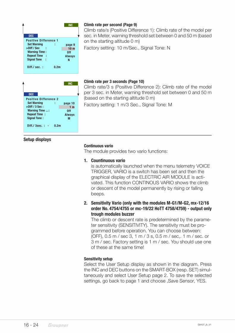
Climb rate per second (Page 9)Climb rate/s (Positive Difference 1): Climb rate of the model per sec. in Meter, warning threshold set between 0 and 50 m (based on the starting altitude 0 m)Factory setting: 10 m/Sec., Signal Tone: N
Climb rate per 3 seconds (Page 10)Climb rate/3 s (Positive Difference 2): Climb rate of the model per 3 sec. in Meter, warning threshold set between 0 and 50 m (based on the starting altitude 0 m)Factory setting: 1 m/3 Sec., Signal Tone: M
Setup displaysContinuous varioThe module provides two vario functions:
1. Countinuous vario is automatically launched when the menu telemetry VOICE TRIGGER, VARIO is a switch has been set and then the graphical display of the ELECTRIC AIR MODULE is acti-vated. This function CONTINOUS VARIO shows the climb or descent of the model permanently by rising or falling beeps.
2. Sensitivity Vario (only with the modules M-G1/M-G2, mx-12/16 order No. 4754/4755 or mc-19/22 HoTT 4758/4759) - output only trough modules buzzer The climb or descent rate is predetermined by the parame-ter sensitivity (SENSITIVITY). The sensitivity must be pro-grammed before operation. You can choose between: (OFF), 0.5 m / sec 3, 1 m / 3 s, 0.5 m / sec,. 1 m / sec. or 3 m / sec. Factory setting is 1 m / sec. You should use one of these at the same time!
Sensitivity setupSelect the User Setup display as shown in the diagram. Press the INC and DEC buttons on the SMART-BOX (resp. SET) simul-taneously and select User Setup page 2. To save the selected settings, go back to page 1 and choose ,Save Sensor‚ YES.
DECPosi t ive Di f ference 1 Set Warning :>Diff / Sec : Warning Time : Repeat Time :Signal Tone :
Diff./ sec. : 0.2m
page 910 m
OffAlways
N
INC
DECPosi t ive Di f ference 2 Set Warning :>Diff / 3 Sec : Warning Time ... : Repeat Time :Signal Tone :
Diff./ 3sec. : - 0.2m
page 101 m
OffAlways
M
INC
17- 24S8437_jh_V1
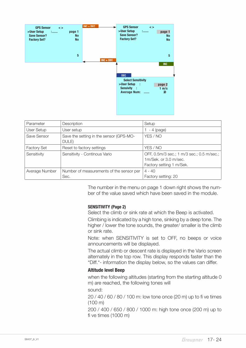
Parameter Description Setup
User Setup User setup 1 - 4 (page)
Save Sensor Save the setting in the sensor (GPS-MO-DULE)
YES / NO
Factory Set Reset to factory settings YES / NO
Sensitivity Sensitivity - Continous Vario OFF, 0.5m/3 sec.; 1 m/3 sec.; 0.5 m/sec.; 1m/Sek. or 3.0 m/sec.Factory setting 1 m/Sek.
Average Number Number of measurements of the sensor perSec.
4 - 40Factory setting: 20
The number in the menu on page 1 down right shows the num-ber of the value saved which have been saved in the module.
SENSITIVITY (Page 2)Select the climb or sink rate at which the Beep is activated. Climbing is indicated by a high tone, sinking by a deep tone. The higher / lower the tone sounds, the greater/ smaller is the climb or sink rate.Note: when SENSITIVITY is set to OFF, no beeps or voice announcements will be displayed.The actual climb or descent rate is displayed in the Vario screen alternately in the top row. This display responds faster than the “Diff.“- information the display below, so the values can differ.
Altitude level Beepwhen the following altitudes (starting from the starting altitude 0 m) are reached, the following tones willsound:20 / 40 / 60 / 80 / 100 m: low tone once (20 m) up to fi ve times (100 m)200 / 400 / 650 / 800 / 1000 m: high tone once (200 m) up to fi ve times (1000 m)
INC + DEC GPS Sensor < >>User Setup : ....... Save Sensor? Factory Set?
page 1NoNo
5
page 1NoNo
5INC + DEC
INC
page 21 m/s
DEC
GPS Sensor < >>User Setup : ....... Save Sensor? Factory Set?
Select Sensitivity >User Setup : Sensivity : Average Num: ...... 20
18 - 24 S8437_jh_V1
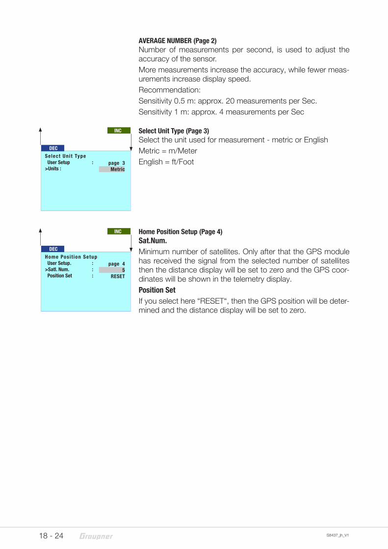
AVERAGE NUMBER (Page 2)Number of measurements per second, is used to adjust the accuracy of the sensor.More measurements increase the accuracy, while fewer meas-urements increase display speed.Recommendation:Sensitivity 0.5 m: approx. 20 measurements per Sec.Sensitivity 1 m: approx. 4 measurements per Sec
Select Unit Type (Page 3)Select the unit used for measurement - metric or EnglishMetric = m/MeterEnglish = ft/Foot
Home Position Setup (Page 4)Sat.Num.Minimum number of satellites. Only after that the GPS module has received the signal from the selected number of satellites then the distance display will be set to zero and the GPS coor-dinates will be shown in the telemetry display. Position SetIf you select here “RESET“, then the GPS position will be deter-mined and the distance display will be set to zero.
DECSelect Uni t Type User Setup :>Units :
page 3Metric
INC
DECHome Posi t ion Setup User Setup . :>Satl. Num. : Position Set :
page 45
RESET
INC
19- 24S8437_jh_V1
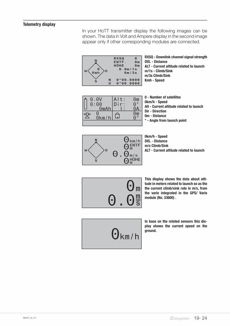
Telemetry displayIn your HoTT transmitter display the following images can be shown. The data in Volt and Ampere display in the second image appear only if other corresponding modules are connected.
0mAh0:000.0V
0km/h0
I:Dir:Alt: 0m
0°0A0m0°
0km/h
0.00m
ms
N
W O
S
Kmh0
km/hENTFm
m/s HÖHEm
00
0.00
NRXSQ 0 ENTF. 0mHÖHE 0m
0.0m/1s 0m/3s 0m/10s
N 0°00.0000O 0°00.0000
W O
S
Kmh0
RXSQ - Downlink channel signal strengthDIS. - DistanceALT - Current altitude related to launchm/1s - Climb/Sinkm/3s Climb/SinkKmh - Speed
0 - Number of satellites0km/h - SpeedAlt - Current altitude related to launchDir - Direction0m - Distance° - Angle from launch point
0km/h - SpeedDIS. - Distancem/s Climb/SinkALT - Current altitude related to launch
This display shows the data about alti-tude in meters related to launch so as the the current climb/sink rate in m/s, from the vario integrated in the GPS/ Vario module (No. 33600) .
In base on the related sensors this dis-play shows the current speed on the ground.
20 - 24 S8437_jh_V1
Firmware update
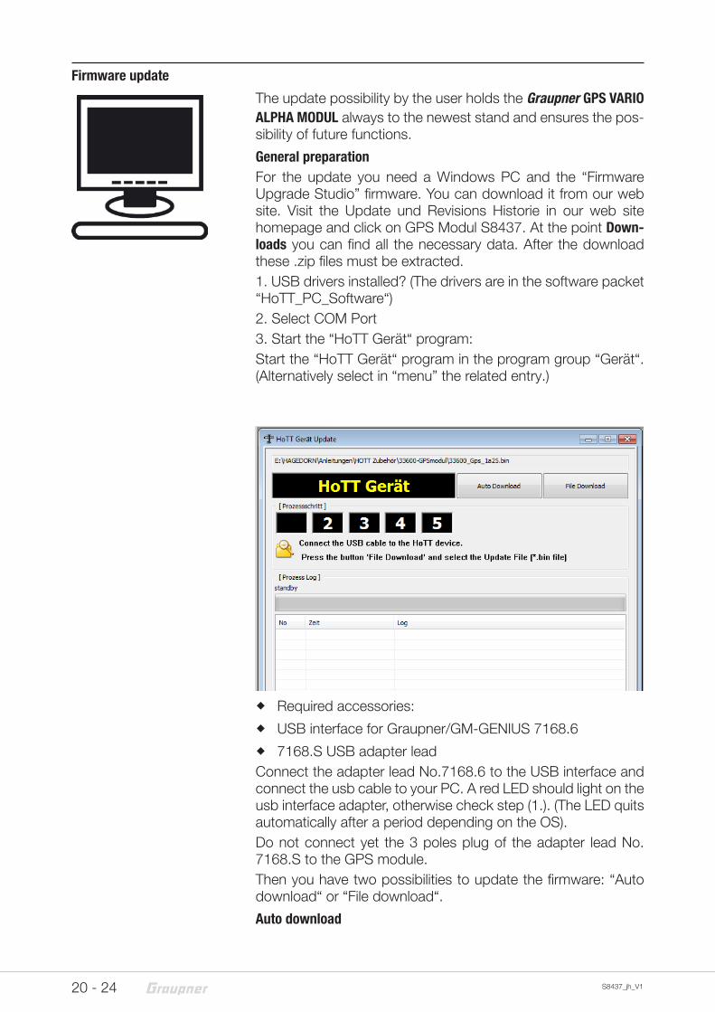
The update possibility by the user holds the Graupner GPS VARIO ALPHA MODUL always to the newest stand and ensures the pos-sibility of future functions.
General preparationFor the update you need a Windows PC and the “Firmware Upgrade Studio” firmware. You can download it from our web site. Visit the Update und Revisions Historie in our web site homepage and click on GPS Modul S8437. At the point Down-loads you can find all the necessary data. After the download these .zip files must be extracted.1. USB drivers installed? (The drivers are in the software packet “HoTT_PC_Software“)2. Select COM Port3. Start the “HoTT Gerät“ program:Start the “HoTT Gerät“ program in the program group “Gerät“. (Alternatively select in “menu” the related entry.)
� Required accessories:
� USB interface for Graupner/GM-GENIUS 7168.6
� 7168.S USB adapter lead Connect the adapter lead No.7168.6 to the USB interface and connect the usb cable to your PC. A red LED should light on the usb interface adapter, otherwise check step (1.). (The LED quits automatically after a period depending on the OS).Do not connect yet the 3 poles plug of the adapter lead No. 7168.S to the GPS module.Then you have two possibilities to update the firmware: “Auto download“ or “File download“.
Auto download
21- 24S8437_jh_V1
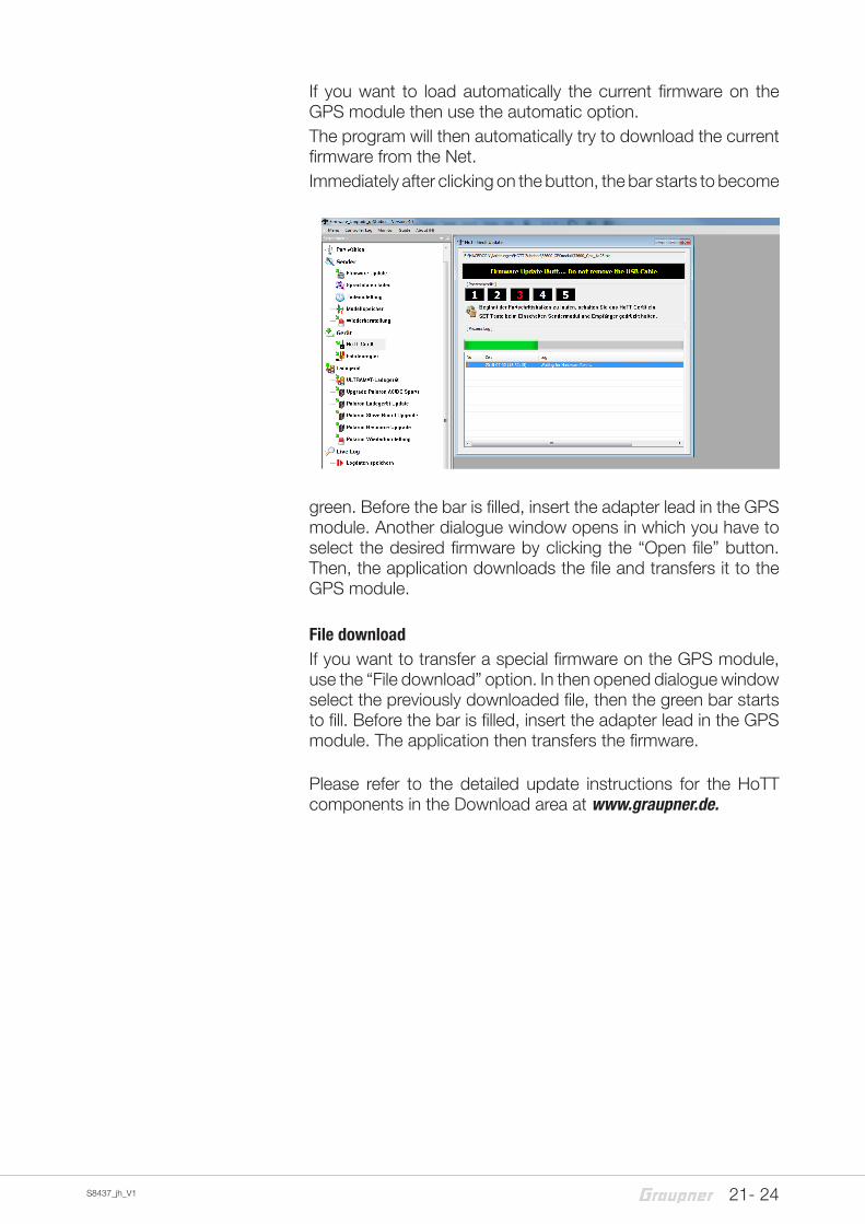
If you want to load automatically the current firmware on the GPS module then use the automatic option.The program will then automatically try to download the current firmware from the Net.Immediately after clicking on the button, the bar starts to become
green. Before the bar is filled, insert the adapter lead in the GPS module. Another dialogue window opens in which you have to select the desired firmware by clicking the “Open file” button. Then, the application downloads the file and transfers it to the GPS module.
File downloadIf you want to transfer a special firmware on the GPS module, use the “File download” option. In then opened dialogue window select the previously downloaded file, then the green bar starts to fill. Before the bar is filled, insert the adapter lead in the GPS module. The application then transfers the firmware.
Please refer to the detailed update instructions for the HoTT components in the Download area at www.graupner.de.
22 - 24 S8437_jh_V1
Declaration of conformity
S8437 GPS Vario Modul AlphaGraupner declares that the product is conform to EU norms.EMV 2004/108/EC: EN 61000-6-1; EN 61000-6-3
23- 24S8437_jh_V1
Notes for environmental protection
Disposal notesThe symbol on this product, its operating instructions or pack-aging gives notice that this product may not be discarded as common household waste at the end of its service life. It must be turned over to a recycling collection point for electric and electronic apparatus.The materials can be recycled according to their markings. You make an important contribution to protection of the environment by utilizing facilities for reuse, material recycling or other means of exploiting obsolete equipment.Batteries must be removed from the unit and disposed of sep-arately at an appropriate collection point. Please inquire with local authorities about the responsible waste collection loca-tions.
Care and maintenance
Notes on careThe product does not need any maintenance, it works so as it is without any special care. In your own interest please protect the model from dust, dirty and humidity!Clean the product only with a dry cloth (do not use detergent!) lightly rub.
Warranty certificateThe Graupner, Henriettenstrassee 96, 73230 Kirchheim/Teck grants from the date of purchase of this product for a period of 24 months. The warranty applies only to the material or opera-tional defects already existing when you purchased the item.Damage due to wear, overloading, incorrect accessories or improper handling are excluded from the guarantee. The legal rights and claims are not affected by this guarantee. Please check exactly defects before a claim or send the product, because we have to ask you to pay shipping costs if the item is free from defects.
The present construction or user manual is for informational pur-poses only and may be changed without prior notice. The cur-rent version can be found on the Internet at www.graupner.de on the relevant product page. In addition, the company Graupner has no responsibility or liability for any errors or inaccuracies that may appear in construction or operation manuals.
No liability can be accepted for printing errors.
P

S8437_jh_V1