Embed Size (px)
Citation preview

Drive System FC2S7 FC2 SERVOLINK 4 Single ProtocolDescription of Profibus to support the SERVOLINK 4 protocol for oneaxis
P-TD-0000187.12010-10-25
SIEB & MEYERW

CopyrightCopyright © 2010 SIEB & MEYER AG.
All rights reserved.
This manual or extracts thereof may only be copied with the explicit authorization ofSIEB & MEYER AG.
TrademarksAll product, font and company names mentioned in this manual may be trademarks or registeredtrademarks of their respective companies.
SIEB & MEYER worldwideFor questions regarding our products and technical problems please contact us.
SIEB & MEYER AGAuf dem Schmaarkamp 2121339 LüneburgGermany
Phone: +49 4131 203 0Fax: +49 4131 203 [email protected]://www.sieb-meyer.de
SIEB & MEYER Shenzhen Trading Co. Ltd.15 H, Seaview BuildingTaizi Road, ShekouShenzenChina
Phone: +86 755 26811417Fax: +86 755 [email protected]://www.sieb-meyer.com
SIEB & MEYER Asia Co. Ltd.4 Fl, No. 532, Sec. 1Min-Sheng N. RoadKwei-Shan Hsiang333 Tao-Yuan HsienTaiwan
Phone: +886 3 311 5560Fax: +886 3 322 [email protected]://www.sieb-meyer.com
SIEB & MEYER USA, LLC4460 Lake Forest Drive, Suite 228Cinncinati, OH 45242USA
Phone: +1 513 563 0860Fax: +1 513 563 [email protected]://www.sieb-meyer.com
W
2 Drive System FC2 - S7 FC2 SERVOLINK 4 Single Protocol

Description of the Program S7FC2Sgl 1
Program Content 2
Program Control 3
Symbols 4
Hardware Configuration in PLC 5
Programming the SERVOLINK 4 gateway 6
Hardware Description 7
Error Detection 8
SERVOLINK 4 gateway Test Assembly 9
Related Documents 10
W Chapter Overview
Drive System FC2 - S7 FC2 SERVOLINK 4 Single Protocol 3

Chapter Overview W
4 Drive System FC2 - S7 FC2 SERVOLINK 4 Single Protocol

1 Description of the Program S7FC2Sgl .............................. 71.1 Installation ................................................................................................... 7
2 Program Content ............................................................... 92.1 Organization block ...................................................................................... 92.2 Function Blocks ........................................................................................... 92.3 Global Data Blocks ..................................................................................... 92.4 Instance Data Blocks .................................................................................. 92.5 User-defined Data Types ............................................................................ 92.6 Inputs ........................................................................................................ 102.7 S7 System Functions and S7 System Function Blocks ............................ 10
3 Program Control .............................................................. 113.1 Organization Block .................................................................................... 113.1.1 Organization block OB_MAINPROG ..................................................................... 113.1.2 Programming the Application Program ................................................................. 113.1.3 Principle PLC Sequence ....................................................................................... 123.2 Function Blocks ......................................................................................... 133.2.1 Function block FB_READDATA ............................................................................ 133.2.1.1 General Description .............................................................................................. 133.2.1.2 Calling the Function Block ..................................................................................... 133.2.1.3 Inputs and Outputs ................................................................................................ 133.2.2 Function block FB_WRITEDATA .......................................................................... 133.2.2.1 General Description .............................................................................................. 133.2.2.2 Calling the Function Block ..................................................................................... 133.2.2.3 Inputs and Outputs ................................................................................................ 143.2.3 Function blockFB_INITAXIS .................................................................................. 143.2.3.1 General Description .............................................................................................. 143.2.3.2 Calling the Function Block ..................................................................................... 143.2.3.3 Inputs and Outputs ................................................................................................ 143.2.4 Function blockFB_SWAP_DINT ............................................................................ 143.2.4.1 General Description .............................................................................................. 143.2.4.2 Calling the Function Block ..................................................................................... 153.2.4.3 Inputs and Outputs ................................................................................................ 153.2.5 Function blockFB_SWAP_INT .............................................................................. 153.2.5.1 General Description .............................................................................................. 153.2.5.2 Calling the Function Block ..................................................................................... 153.2.5.3 Inputs and Outputs ................................................................................................ 153.3 Global Data Blocks ................................................................................... 153.3.1 Data Block DB_ERRORCODE .............................................................................. 153.3.2 Data Block DB_GLOBALDATA ............................................................................. 163.4 Instance Data Blocks ................................................................................ 163.5 User-defined Data Types .......................................................................... 163.5.1 User-defined Data Type AXIS_DATA_IN .............................................................. 163.5.2 User-defined Data Type AXIS_DATA_OUT .......................................................... 173.5.3 User-defined Data Type AXIS_DATA ................................................................... 183.6 System Functions and Blocks ................................................................... 18
4 Symbols .......................................................................... 194.1 Symbol Table ............................................................................................ 19
5 Hardware Configuration in PLC ...................................... 21
W Content
Drive System FC2 - S7 FC2 SERVOLINK 4 Single Protocol 5
5.1 GSD File ................................................................................................... 215.2 Settings in the Hardware Configuration .................................................... 215.3 Defining the Addresses in the Modules .................................................... 22
6 Programming the SERVOLINK 4 gateway ...................... 23
7 Hardware Description ...................................................... 257.1 Connecting of the Gateway ....................................................................... 25
8 Error Detection ................................................................ 278.1 Errors in S7 PLC ....................................................................................... 278.2 Error in Drive Control FC2 ........................................................................ 27
9 SERVOLINK 4 gateway Test Assembly .......................... 299.1 Front Panel Check of SIMATIC CPU ........................................................ 299.1.1 LED Display .......................................................................................................... 299.2 Drive Check .............................................................................................. 299.3 Motor Control ............................................................................................ 29
10 Related Documents ......................................................... 31
Content W
6 Drive System FC2 - S7 FC2 SERVOLINK 4 Single Protocol
1 Description of the ProgramS7FC2SglThe program S7FC2Sgl makes it possible to connect the FC2 modules bySIEB & MEYER to a SIMATIC S7 CPU with Profibus interface via a SERVOLINK 4gateway. The program has been created using the engineering tool S7-SCL V5.1. Alldata blocks necessary for the communication are involved in the program. In additionthe program provides three system blocks of the S7, which are used during the proc‐ess.
In order to use the program for the communication between the S7 and the FC2 devi‐ces by SIEB & MEYER, you need the following hardware and software components:< SIMATIC STEP 7 starting form version 4.02< SIMATIC S7 300(/400) starting from CPU 315-2DP< SIEB & MEYER SERVOLINK 4 gateway< SIEB & MEYER FC2
The used communication protocol is based on the custom-designed drive profileDS402 by CANopen.
1.1 Installation✦ At first create a directory for the application program.
Example: D:\Data\Siemens\SM_AG\S7Prog✦ Copy the ZIP file of the program (e.g."S7FC2Sgl_V100.zip") into the created direc‐
tory.✦ Unpack the ZIP file.✦ Start the SIMATIC Manager.✦ Select the menu "File ÿ Open".✦ Click the button "Browse" to select the created directory and open the project
"S7FC2Sgl".
W Description of the Program S7FC2Sgl
Drive System FC2 - S7 FC2 SERVOLINK 4 Single Protocol 7
1

Description of the Program S7FC2Sgl W
8 Drive System FC2 - S7 FC2 SERVOLINK 4 Single Protocol
1

2 Program ContentThe program S7FC2Sgl contains the following objects as SCL sources. As SCL sour‐ces they can be compiled to function and data blocks with the desired block numbervia the symbol table.
2.1 Organization blockSymbolic name Description
OB_MAINPROG Example main program
2.2 Function BlocksSymbolic name Description
FB_INITAXIS Initializing the bus data
FB_READDATA Analyzing the bus data towards the axis structure
FB_WRITEDATA Compiling the bus data from axis structure
FB_SWAP_DINT Swapping the bytes of a LongInteger value
FB_SWAP_INT Swapping the bytes of an Integer value
2.3 Global Data BlocksSymbolic name Description
DB_ERRORCODE Error codes
DB_GLOBALDATA Global used variables
2.4 Instance Data BlocksSymbolic name Description
DB_INITAXIS Data block for data initializing of axis 0
DB_READDATA Data block for read function
DB_WRITEDATA Data block for write function
DB_SWAP_DINT Data block for DINT swap function
DB_SWAP_INT Data block for INT swap function
2.5 User-defined Data TypesSymbolic name Description
AXIS_DATA_IN Data structure of the received data from Profibus
AXIS_DATA_OUT Data structure of the transmitted data to Profibus
W Program Content
Drive System FC2 - S7 FC2 SERVOLINK 4 Single Protocol 9
2

Symbolic name Description
AXIS_DATA Data structure of the axis data
2.6 InputsVia the inputs the connected axes can be controlled.Variable Address Meaning
IN_REGON IX0.0 Switch on
IN_START IX0.1 Enable speed
IN_QCKSTP IX0.2 Quick stop
IN_RESET IX0.7 Error reset
IN_SPEED IB4 Speed setting [rpm] (value = 0..9)Axis 0: value × 100
2.7 S7 System Functions and S7 System FunctionBlocksFunction block Symbolic name Description
SFC14 DPRD_DAT Read DP slaves
SFC15 DPWR_DAT Write DP slave
Program Content W
10 Drive System FC2 - S7 FC2 SERVOLINK 4 Single Protocol
2

3 Program ControlThis chapter provides information on the individual blocks and their functions.
3.1 Organization Block
3.1.1 Organization block OB_MAINPROGThe program is controlled via the organization block OB_MAINPROG. This block givesan example in which way the information is transmitted. The data from the bus areread, allocated to the axes, processed and written to the bus again. The individual pro‐gram steps are processed by the function blocks.
Please note that the data from the Profibus module first must be copied into the axisstructure via the SFC14. Using the function block FB_READDATA the data is then an‐alyzed in the axis structure. After analyzing is complete the data is processed using thefunction block FB_WRITEDATA and the adjacent inputs. Then the data is transferredto the axis structure and copied into the Profibus module via the SFC15. Before theproper sequential control comes into operation, the data must be initialized ones whenthe program is started or after a fault.
3.1.2 Programming the Application ProgramAt the beginning of the program cycle the data area of the Profibus must be read usingthe system function SFC14, DPRD_DAT,. Afterwards the data must be assigned to thedifferent axes via the function block FB_READDATA. This function must be called oncefor each FC2 module.
In order to align the data between the module status and the PLC status, the functionblock FB_INITAXIS should be called for each FC2 module once when starting the PLCand after a fault..
Afterwards the data can be processed and the new parameters and control commandscan be generated using the function block FB_WRITEDATA.
At the end of the program cycle the data must be written into the data area of the Profi‐bus via the system function SFC15, DPWR_DAT,. This function must be called oncefor each FC2 DP slave.
The cycle starts again: load → process → output.
W Program Control
Drive System FC2 - S7 FC2 SERVOLINK 4 Single Protocol 11
3

3.1.3 Principle PLC Sequence
Fig. 1: Program sequence
Program Control W
12 Drive System FC2 - S7 FC2 SERVOLINK 4 Single Protocol
3

3.2 Function Blocks
3.2.1 Function block FB_READDATA
3.2.1.1 General DescriptionThe function block FB_READDATA processes the data of the FC2 DP slave. The dataof the FC2 device is filtered by the function block so that individual information blocksare created. The information is deposited in the axis structure. Thus it is globally avail‐able in the whole application program. In order to process the data, parameters mustbe passed to the function block (FB). At the output of the block an error informationand the actual values are upcoming.
This function block must be called for each FC2 device, e.g. at the beginning of eachPLC cycle.
3.2.1.2 Calling the Function BlockFB_READDATA.DB_READDATA
(Axis := DB_GLOBALDATA.SD_Axis[0]);
3.2.1.3 Inputs and Outputs
Parameter In / Out Type Description
Axis in_out AXIS_DATA Data structure of the axis
ErrorID out WORD Error code
Act_Position out DINT Actual position
Act_Velocity out REAL actual velocity
Act_Current out REAL actual current
3.2.2 Function block FB_WRITEDATA
3.2.2.1 General DescriptionFB_WRITEDATAThe function block WR_DNC compiles a reference value telegramfrom the data in the axis structure and the parameter values and writes the new param‐eters and control bits into the axis structure. In order to write into a DP slave, parame‐ters must be passed to the function block (FB). At the output of the block an error infor‐mation is upcoming.
This function block must be called for each FC2 device, e.g. at the end of each PLCcycle.
3.2.2.2 Calling the Function BlockFB_WRITEDATA.DB_WRITEDATA
(Fault_Reset := IX0.7, Regulator_On := IX0.0, Start := IX0.1, QuickStop := IX0.2,
W Program Control
Drive System FC2 - S7 FC2 SERVOLINK 4 Single Protocol 13
3

Velocity := INT_TO_REAL (WORD_TO_INT (BYTE_TO_WORD (IB4))) * 100.0,
Current := 1.0, Axis := DB_GLOBALDATA.SD_Axis[0]);
3.2.2.3 Inputs and Outputs
Parameter In / Out Type Description
Axis in_out AXIS_DATA Data structure of the axis
FAULT_RESET in BOOL Reset of the axis error
Regulator_On in BOOL Switching on the output stage
Start in BOOL Enable movements
QuickStop in BOOL Quick stop
Velocity in INT Speed setting
Current in INT Preset maximum current value
ErrorID out WORD Error code
3.2.3 Function blockFB_INITAXIS
3.2.3.1 General DescriptionUsing the function block FB_INITAXIS the command bits are initialized and depositedin the axis structure. The reference values are initialized with the value zero.
During initialization the service channel in the drive sets the number of spindles (object154) to the value 1 and the spindle selection (object 153) to 0.
3.2.3.2 Calling the Function BlockFB_INITAXISDB_INITAXIS(Axis := DB_GLOBALDATA.SD_Axis[0]);
3.2.3.3 Inputs and Outputs
Parameter In / Out Type Description
Axis in_out AXIS_DATA Data structure of the axis
3.2.4 Function blockFB_SWAP_DINT
3.2.4.1 General DescriptionUsing the function block FB_SWAP_DINT the byte order of a LongInteger value isswapped.
Byte order before: byte0, byte1, byte2, byte3
Byte order after: byte3, byte2, byte1, byte0
Program Control W
14 Drive System FC2 - S7 FC2 SERVOLINK 4 Single Protocol
3

3.2.4.2 Calling the Function BlockFB_SWAP_DINT.DB_FB_SWAP_DINT
(value := Axis.InData.Act_Position);
3.2.4.3 Inputs and Outputs
Parameter In / Out Type Description
value in_out DINT Variable for swapping
3.2.5 Function blockFB_SWAP_INT
3.2.5.1 General DescriptionUsing the function block FB_SWAP_INT the byte order of an Integer value is swapped.
Byte order before: byte0, byte1
Byte order after: byte1, byte0
3.2.5.2 Calling the Function BlockFB_SWAP_INT.DB_FB_SWAP_INT (value := Axis.InData.Act_Velocity);
3.2.5.3 Inputs and Outputs
Parameters In / Out Type Description
value in_out INT Variable for swapping
3.3 Global Data Blocks
3.3.1 Data Block DB_ERRORCODEThe global data block DB_ERRORCODE contains the structure of the error codes thatare returned by the function block.
The error codes have the following meanings:Error code Value Meaning
ERR_None 0 no error
ERR_WrongState 1 The axis is in the wrong device status for the upcom‐ing command.
ERR_Parameter 2 Parameter error
ERR_SERVOLINK_Fault 6 SERVOLINK error
ERR_SERVOLINK_Slot 7 SERVOLINK slot error
W Program Control
Drive System FC2 - S7 FC2 SERVOLINK 4 Single Protocol 15
3

3.3.2 Data Block DB_GLOBALDATAThe global data block DB_GLOBALDATA contains the structure of the program-rele‐vant data that must be adapted to the particular project.
The following variables are used:Variable Type Initial value Meaning
DP_Base_Address WORD W#16#100 Base address Profibus
SD_Axis AXIS_DATA 0 ARRAY[0..9] of the axis structure
3.4 Instance Data BlocksA separate set of instance data blocks is required for each axis. Each instance datablock contains the input parameters, the output parameters, the in-out parameters andthe static variables of the respective function block.
3.5 User-defined Data TypesThe user-defined data types describe the data structure of each axis and the input andoutput data of the Profibus module.
The data can be accessed via the global variables.
The structure of AXIS_DATA is based on the standards by the PLCopen group.Thestructures of the bus parameters are based on the CANopen protocol. A description ofthe telegram structure is part of the FC2 device description.
3.5.1 User-defined Data Type AXIS_DATA_INThe user-defined data type AXIS_DATA_IN contains the data structure of the receiveddata of a module from the Profibus.
Name Type Meaning
Status word byte 0..1
ReadyToSwitchOn BOOL Ready to be switched on
SwitchedOn BOOL Switched on
OperationEnabled BOOL Operation is enabled
Fault BOOL Fault occurred
VoltageEnabled BOOL Voltage is enabled
QuickStop BOOL Quick stop
SwitchOnDisabled BOOL Switch on is disabled
Warning BOOL Warning
smres010 BOOL reserved
Remote BOOL Remote mode
TargetReached BOOL Reference value reached
InternalLimitActive BOOL Internal limit reached
OperationModeSpecific0 BOOL Dependent on the operating mode
OperationModeSpecific1 BOOL Dependent on the operating mode
Program Control W
16 Drive System FC2 - S7 FC2 SERVOLINK 4 Single Protocol
3

Name Type Meaning
ActualValueTelegramCode1 BOOL Code of actual value telegram
ActualValueTelegramCode0 BOOL Code of actual value telegram
Actual values byte 2..9
Act_Position DINT Actual position
Act_Velocity INT actual velocity
Act_Current INT actual current
Service channel byte 10..15
ServiceReturn DINT Return parameters / error code
res14 Byte reserved
ServiceDoneToggle BOOL Return toggle bit
ServiceFault BOOL Error
smres152 to smres157 6 * BOOL reserved
3.5.2 User-defined Data Type AXIS_DATA_OUTThe user-defined data type AXIS_DATA_OUT contains the data structure of the trans‐mission data of a module to the Profibus.
Name Type Meaning
Control word byte 0..1
SwitchOn BOOL Switch on power unit
EnableVoltage BOOL Enable voltage at the power unit
QuickStop BOOL Quick stop
EnableOperation BOOL Operation enable
Mode0 BOOL Operation mode bit 0
Mode1 BOOL Operation mode bit 1
Mode2 BOOL Operation mode bit 2
FaultReset BOOL Error reset
Hold BOOL Hold
res011 BOOL reserved
res012 BOOL reserved
smres013 BOOL reserved
smres014 BOOL reserved
smres015 BOOL reserved
ReferenceValueTelegramID0 BOOL Code of reference value telegram
ReferenceValueTelegramID1 BOOL Code of reference value telegram
Reference values byte 2..7
res02 INT reserved
Spt_Velocity INT reference speed
Spt_Current INT Maximum reference current
Byte 8
res08 Byte reserved
Service channel byte 9..15
ServiceValidToggle BOOL New service command
ServiceFunction0 BOOL Service function
ServiceFunction1 BOOL
W Program Control
Drive System FC2 - S7 FC2 SERVOLINK 4 Single Protocol 17
3

Name Type Meaning
ServiceByteIndex0 BOOL Number of bytes
ServiceByteIndex1 BOOL
smres095 to smres097 3 * BOOL reserved
ServiceIndex INT Object number
ServiceValue DINT Object value / array index
3.5.3 User-defined Data Type AXIS_DATAThe user-defined data type AXIS_DATA contains the data structure of the axis databased on the PLCopen standard.
Name Type Meaning
init_ok BOOL TRUE: all parameters are initialized
State_NotReadyToSwitchOn BOOL Module status that is made up of the statusbits 0 ... 3 and 5 ... 6 of the bus protocol.There is always only one module state set,the others are not set.
State_SwitchOnDisabled BOOL
State_ReadyToSwitchOn BOOL
State_SwitchedOn BOOL
State_OperationEnabled BOOL
State_QuickStopActive BOOL
State_FaultReactActive BOOL
State_Fault BOOL
InData AXIS_DATA_IN Data block (PB->PLC)
OutData AXIS_DATA_OUT Data block (PLC->PB)
3.6 System Functions and BlocksThe blocks of the S7 system functions are described in the according manuals by SIE‐MENS.
Program Control W
18 Drive System FC2 - S7 FC2 SERVOLINK 4 Single Protocol
3

4 SymbolsAll function and data blocks receive a block number during compiling. These blocknumbers can be assigned in the symbol table.
The blocks then can be called using their number (DB10 or FB10) or their symbolnames (DB_INITAXIS, FB_INITAXIS).
4.1 Symbol TableAs an example in the following you see an extract of the symbol table including the as‐signment of the block numbers. Individual instance blocks are assigned to each axis.
Symbol Address Data type Comment
DB_FB_SWAP_DINT DB2 FB2 Instance data block
DB_FB_SWAP_INT DB3 FB3 Instance data block
DB_INITAXIS DB10 FB10 Instance data block
DB_READDATA DB20 FB20 Instance data block
DB_WRITEDATA DB30 FB30 Instance data block
DB_ERRORCODE DB40 DB40 Global data block
DB_GLOBALDATA DB50 DB50 Global data block
FB_SWAP_DINT FB2 FB2 Function block
FB_SWAP_INT FB3 FB3 Function block
FB_INITAXIS FB10 FB10 Function block
FB_READDATA FB20 FB20 Function block
FB_WRITEDATA FB30 FB30 Function block
OB_MAINPROG OB1 OB1 Organization block
DPRD_DAT SFC14 SFC14 System function
DPWR_DAT SFC15 SFC15 System function
AXIS_DATA_IN UDT1 UDT1 User-defined data type
AXIS_DATA_OUT UDT2 UDT2 User-defined data type
AXIS_DATA UDT3 UDT3 User-defined data type
W Symbols
Drive System FC2 - S7 FC2 SERVOLINK 4 Single Protocol 19
4

Symbols W
20 Drive System FC2 - S7 FC2 SERVOLINK 4 Single Protocol
4

5 Hardware Configuration in PLCThe SIEB & MEYER modules are addresses by the SERVOLINK 4 interface of theSERVOLINK 4 gateway. This converter is projected via the Profibus DP as DP slave inthe software SIEMENS Step 7 with inputs and outputs of 16 byte each according to thenumber of FC2 modules. Therefore the appropriate GSD file by SIEB & MEYER is re‐quired. Please refer to the SIMATIC documentation on how to integrate new GSD filesinto the programming environment.
5.1 GSD FileIn order to project the device on the PLC the GSD file SM_SLGW.GSD is required.
5.2 Settings in the Hardware ConfigurationAt first the object "SERVOLINK 4 gateway" is dragged to the Profibus DP master sys‐tem in the station window of the "HW Config".
Fig. 2: SIMATIC software "HW Config"
The inserted module is highlighted. By double-click the properties window is opened.There you can enter a module name and assign the Profibus address.
W Hardware Configuration in PLC
Drive System FC2 - S7 FC2 SERVOLINK 4 Single Protocol 21
5

Fig. 3: Dialog window "Properties - DP slave"
In the lower part of the station window the detailed view of the converter is indicated intable form.
According to the used drives the objects "DS402 Single Axis" or "DS402 Double Axis"are dragged into the detailed view of the "HW Config". By double-click you can open aproperties window again and define the addresses of the input and the output area.
Fig. 4: Dialog window "Properties - DP slave"
5.3 Defining the Addresses in the ModulesBesides defining the addresses in the PLC also the FC2 modules and the SERVO‐LINK 4 gateway must be set to the right address. Refer to the device documentationfor additional information.
Hardware Configuration in PLC W
22 Drive System FC2 - S7 FC2 SERVOLINK 4 Single Protocol
5

6 Programming the SERVOLINK 4gatewayCustomized programming is not required. The converter automatically detects thenumber of modules connected to it.
W Programming the SERVOLINK 4 gateway
Drive System FC2 - S7 FC2 SERVOLINK 4 Single Protocol 23
6

Programming the SERVOLINK 4 gateway W
24 Drive System FC2 - S7 FC2 SERVOLINK 4 Single Protocol
6
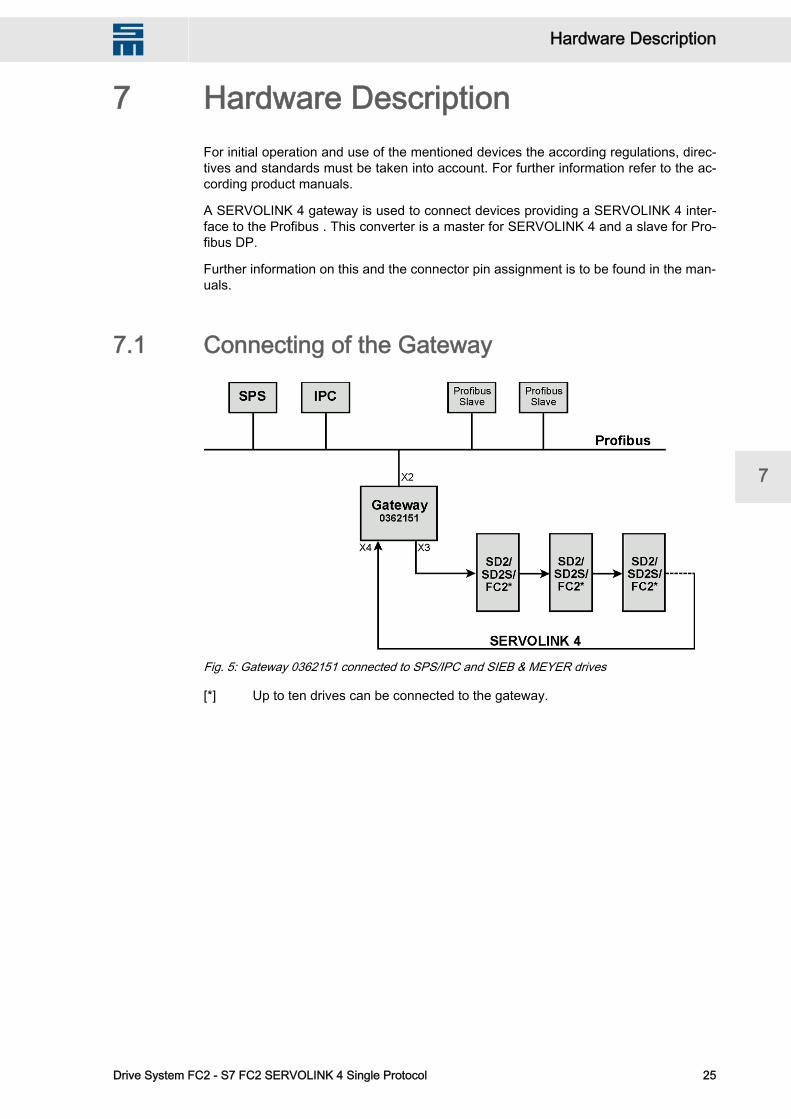
7 Hardware DescriptionFor initial operation and use of the mentioned devices the according regulations, direc‐tives and standards must be taken into account. For further information refer to the ac‐cording product manuals.
A SERVOLINK 4 gateway is used to connect devices providing a SERVOLINK 4 inter‐face to the Profibus . This converter is a master for SERVOLINK 4 and a slave for Pro‐fibus DP.
Further information on this and the connector pin assignment is to be found in the man‐uals.
7.1 Connecting of the Gateway
Fig. 5: Gateway 0362151 connected to SPS/IPC and SIEB & MEYER drives
[*] Up to ten drives can be connected to the gateway.
W Hardware Description
Drive System FC2 - S7 FC2 SERVOLINK 4 Single Protocol 25
7

Hardware Description W
26 Drive System FC2 - S7 FC2 SERVOLINK 4 Single Protocol
7

8 Error DetectionIn the following several errors regarding the conversion from Profibus to SERVOLINK 4and their detection are described.
8.1 Errors in S7 PLCPLC failure
The converter detects a bus error and sets the output data to the SERVOLINK 4 tozero. The drive FC2 switches off because the control word has the value zero.
PLC stops
S7 PLC sets the output data to zero. The converter forwards this data to the SERVO‐LINK 4. The drive FC2 switches off because the control word has the value zero.
System Function Block SFC 15
When the system function block SFC 15 is not called, the present data pattern is keptand sent again and again. The converter forwards this data to the SERVOLINK 4. Thedrive is not able to distinguish whether the same data shall be sent repeatedly or theblock can not be called.
8.2 Error in Drive Control FC2A failure of the drive FC2 causes that the SERVOLINK 4telegram is replied faulty ornot at all.
Thus the converter detects an error. The device distinguishes between a general errorin the SERVOLINK 4 and a slot error of an individual participant. If a general error isdetected, the output data to the field bus are set to zero. If a slot error is detected, theoutput data are set to 0FFh. The status in the PLC program can be set correspondinglyand the PLC program can be set to switch to an error routine.
W Error Detection
Drive System FC2 - S7 FC2 SERVOLINK 4 Single Protocol 27
8

Error Detection W
28 Drive System FC2 - S7 FC2 SERVOLINK 4 Single Protocol
8

9 SERVOLINK 4 gateway TestAssemblyThe test assembly is done as shown in the hardware description. When the system isconnected and ready for operation you can start checking.
9.1 Front Panel Check of SIMATIC CPUThe front panel provides several LEDs that indicate the status of the CPU. The LEDindicating the power supply "DC5V" and the LED "RUN" must be on permanently. Thismakes sure that the PLC program is running.
In the event of an error the PLC switches to the stop mode. In order to fix the error youmust check that the converter is connected correctly. Check also whether the rightnumber of drives is connected.
9.1.1 LED DisplayThe meaning of each LED on the front panel of the SIMATIC CPU is described in thefollowing table.LED State Meaning
SF LED on Error in PLC
BATF LED on Battery error
BUSF LED on Bus error
DC5V LED on Power supply of 5 V present
FRCE LED on Output data of PLC is frozen.
RUN LED on PLC program is running.
Stop LED on PLC program has been stopped.
9.2 Drive CheckYou can check the received SERVOLINK 4 data using the bus monitor in the softwaredrivemaster2.
9.3 Motor ControlWhen a motor is connected to the drive, it can be controlled via the inputs of the PLC.< Via the input i0 the output stage is switched on.< Via the input i1 the operation is enabled and the motor can rotate.< Via the input i2 the quick stop function is activated.< Via the input i7 an axis error can be reset.
In the demo program you can preset the speed via the input area IB4 (value = 0...9).< For axis 0 the speed "value * 100 " is preset.
In the demo program the current setting has the fixed value 10 %.
W SERVOLINK 4 gateway Test Assembly
Drive System FC2 - S7 FC2 SERVOLINK 4 Single Protocol 29
9

The speed and current settings are passed standardized using the maximum valuesthat are read from the drives during initialization.
SERVOLINK 4 gateway Test Assembly W
30 Drive System FC2 - S7 FC2 SERVOLINK 4 Single Protocol
9

10 Related DocumentsThe following documents provide more information on this topic:Supplier Document name
SIEMENS Manuals regarding Step 7 programming
SIEB & MEYER AG Gateway_0362151.pdf
SIEB & MEYER AG drivemaster2_UserManual.pdf
W Related Documents
Drive System FC2 - S7 FC2 SERVOLINK 4 Single Protocol 31
10

Related Documents W
32 Drive System FC2 - S7 FC2 SERVOLINK 4 Single Protocol
10