Embed Size (px)
Citation preview
SIMATIC NET
S7-CPs for Industrial Ethernet
Manual Part B
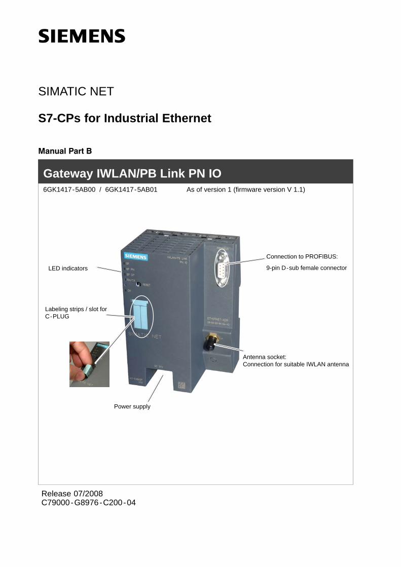
LED indicators
Gateway IWLAN/PB Link PN IO 6GK1417-5AB00 / 6GK1417-5AB01 As of version 1 (firmware version V 1.1)
Antenna socket:Connection for suitable IWLAN antenna
Connection to PROFIBUS:
9-pin D-sub female connector
Labeling strips / slot forC-PLUG
Power supply
Release 07/2008C79000-G8976-C200-04
Notes on the product
B-2Gateway IWLAN/PB Link PN IO for Industrial Ethernet / Manual Part B
Release 07/2008
C79000-G8976-C200-04
Notes on the product
Product names:
This description contains information on the product
IWLAN/PB Link PN IO Order no.: 6GK1417-5AB00Order no.: 6GK1417-5AB01 (US variant)
Product information accompanying the product
Notice
All the notes provided in the compact operating instructions supplied with thedevice described here are valid and must be observed.
General information about the documentation
All the documents mentioned here can be found on the SIMATIC NET IndustrialWireless LAN CD supplied with the IWLAN/PB Link PN IO or are available viaInternet.
Documentation about the IWLAN/PB Link PN IO
”S7 CPs for Industrial Ethernet Configuration and Commissioning” manual withthe following components:
- General Part A
Contains basic information about operating, configuring, and diagnosing CPsand gateways for SIMATIC S7.
- Device-specific Part BL2 ”IWLAN/PB Link PN IO Gateway” (this documentation)
Contains information about installation, commissioning, and configuration.
Operating Instructions (compact) - hard copy
Contains safety instructions, certifications, and warnings.
Additional documentation about operating the IWLAN/PB Link PN IO
Ooperating InstructionsSCALANCE W788-xPRO/RR /SCALANCE W74x-1PRO/RR
RCoax system manual
Contents
B-3Gateway IWLAN/PB Link PN IO for Industrial Ethernet / Manual Part BRelease 07/2008
C79000-G8976-C200-04
Contents
Contents - Part A
S7-CPs - General information see general part. . . . . . . . . . . . . . . . . . . . . . . .
Note
Please remember that Part A of the manual also belongs to the description of theCP / Link. This contains - among other things - an explanation of the safetyinstrucions provided, references, and further information about all S7-CPs /IWLAN/IE/PB Link for Industrial Ethernet.
The following revision level of Part A belongs to Part B of the manual: as of1/2005
You can download the current general Part A from the Internet:
http://support.automation.siemens.com/WW/news/en/8777865
Contents - Part BL2
Notes on the product B-2. . . . . . . . . . . . . . . . . . . . . . . . . . . . . . . . . . . . . . . . . . . . . . . . . . .
General information about the documentation B-2. . . . . . . . . . . . . . . . . . . . . . . . . . . .
Contents B-3. . . . . . . . . . . . . . . . . . . . . . . . . . . . . . . . . . . . . . . . . . . . . . . . . . . . . . . . . . . . . . .
1 Properties and Services B-5. . . . . . . . . . . . . . . . . . . . . . . . . . . . . . . . . . . . . . . . . . . . . . . .
2 Structure B-11. . . . . . . . . . . . . . . . . . . . . . . . . . . . . . . . . . . . . . . . . . . . . . . . . . . . . . . . . . . . . .
3 Installation and Commissioning B-12. . . . . . . . . . . . . . . . . . . . . . . . . . . . . . . . . . . . . . . . .
3.1 Installation and Parameter Assignment with the PRESET PLUG B-13. . . .
3.2 Configuring the PRESET PLUG B-15. . . . . . . . . . . . . . . . . . . . . . . . . . . . . . . .
3.3 Establishing the Connections B-17. . . . . . . . . . . . . . . . . . . . . . . . . . . . . . . . . . 3.3.1 Important Notes B-17. . . . . . . . . . . . . . . . . . . . . . . . . . . . . . . . . . . . . . . . . . . . . . 3.3.2 PG/PC Connection B-18. . . . . . . . . . . . . . . . . . . . . . . . . . . . . . . . . . . . . . . . . . . 3.3.3 Power Supply B-19. . . . . . . . . . . . . . . . . . . . . . . . . . . . . . . . . . . . . . . . . . . . . . . .
3.4 Installation and Parameter Assignment without the PRESET PLUG B-20.
3.5 C-PLUG (Configuration Plug) B-22. . . . . . . . . . . . . . . . . . . . . . . . . . . . . . . . . .
4 Configuration with STEP 7 B-25. . . . . . . . . . . . . . . . . . . . . . . . . . . . . . . . . . . . . . . . . . . . . .
4.1 Use as a PROFINET IO Device and as a Gateway B-26. . . . . . . . . . . . . . . 4.1.1 Configuring the Properties with STEP 7 B-26. . . . . . . . . . . . . . . . . . . . . . . . . 4.1.2 Update Time for the PROFINET IO System B-28. . . . . . . . . . . . . . . . . . . . . . 4.1.3 Assigning Device Names and Downloading the Configuration B-30. . . . . .
4.2 Use As a Gateway Only B-31. . . . . . . . . . . . . . . . . . . . . . . . . . . . . . . . . . . . . . .
Contents
B-4Gateway IWLAN/PB Link PN IO for Industrial Ethernet / Manual Part B
Release 07/2008
C79000-G8976-C200-04
4.2.1 Configuring the Properties with STEP 7 B-31. . . . . . . . . . . . . . . . . . . . . . . . . 4.2.2 Assigning the IP Address and Loading the Configuration B-32. . . . . . . . . . .
4.3 Parameters in the Properties Dialog Box for IWLAN/PB Link PN IO B-33. 4.3.1 Setting the Properties in the Basic Module B-34. . . . . . . . . . . . . . . . . . . . . . . 4.3.2 Setting Properties in the IWLAN Interface Submodule B-35. . . . . . . . . . . . . 4.3.3 Setting the Properties in the PROFIBUS Submodule B-36. . . . . . . . . . . . . .
5 Restoring the Standard Settings B-37. . . . . . . . . . . . . . . . . . . . . . . . . . . . . . . . . . . . . . . .
5.1 WLAN Settings as Shipped (Default Status) B-37. . . . . . . . . . . . . . . . . . . . . .
5.2 Memory Reset or Resetting to Factory Settings B-38. . . . . . . . . . . . . . . . . . 5.2.1 Memory Reset B-38. . . . . . . . . . . . . . . . . . . . . . . . . . . . . . . . . . . . . . . . . . . . . . . 5.2.2 Resetting to the Factory Settings using NCM Diagnostics -
(WLAN parameters are retained) B-39. . . . . . . . . . . . . . . . . . . . . . . . . . . . . . . 5.2.3 Resetting to Factory Settings with the RESET Button -
WLAN parameters are reset) B-39. . . . . . . . . . . . . . . . . . . . . . . . . . . . . . . . . .
6 LEDs B-41. . . . . . . . . . . . . . . . . . . . . . . . . . . . . . . . . . . . . . . . . . . . . . . . . . . . . . . . . . . . . . . . . .
7 Performance Data B-43. . . . . . . . . . . . . . . . . . . . . . . . . . . . . . . . . . . . . . . . . . . . . . . . . . . . . .
7.1 Characteristic Data for Wireless Links B-43. . . . . . . . . . . . . . . . . . . . . . . . . . .
7.2 S7 Communication Characteristics B-43. . . . . . . . . . . . . . . . . . . . . . . . . . . . .
7.3 Features of Data Record Routing B-43. . . . . . . . . . . . . . . . . . . . . . . . . . . . . . .
7.4 Total Number of Connections B-44. . . . . . . . . . . . . . . . . . . . . . . . . . . . . . . . . .
7.5 Characteristic Data for PROFINET IO B-44. . . . . . . . . . . . . . . . . . . . . . . . . . .
8 Compatibility with Predecessor Products B-45. . . . . . . . . . . . . . . . . . . . . . . . . . . . . . . .
8.1 Use as a replacement: B-45. . . . . . . . . . . . . . . . . . . . . . . . . . . . . . . . . . . . . . . .
9 Further notes regarding operation B-47. . . . . . . . . . . . . . . . . . . . . . . . . . . . . . . . . . . . . .
9.1 Changing interface parameters during download B-47. . . . . . . . . . . . . . . . . .
9.2 Time forwarding B-47. . . . . . . . . . . . . . . . . . . . . . . . . . . . . . . . . . . . . . . . . . . . . .
9.3 SNMP agent B-47. . . . . . . . . . . . . . . . . . . . . . . . . . . . . . . . . . . . . . . . . . . . . . . . .
9 How to Load New Firmware B-49. . . . . . . . . . . . . . . . . . . . . . . . . . . . . . . . . . . . . . . . . . . . .
11 Technical data B-50. . . . . . . . . . . . . . . . . . . . . . . . . . . . . . . . . . . . . . . . . . . . . . . . . . . . . . . .
11.1 Technical Specifications of the Module B-50. . . . . . . . . . . . . . . . . . . . . . . . . . 11.1.1 Standards and Approvals B-51. . . . . . . . . . . . . . . . . . . . . . . . . . . . . . . . . . . . . .
12 FCC Approval B-52. . . . . . . . . . . . . . . . . . . . . . . . . . . . . . . . . . . . . . . . . . . . . . . . . . . . . . . .
1 Properties and Services
B-5Gateway IWLAN/PB Link PN IO for Industrial Ethernet / Manual Part BRelease 07/2008
C79000-G8976-C200-04
1 Properties and Services
Application
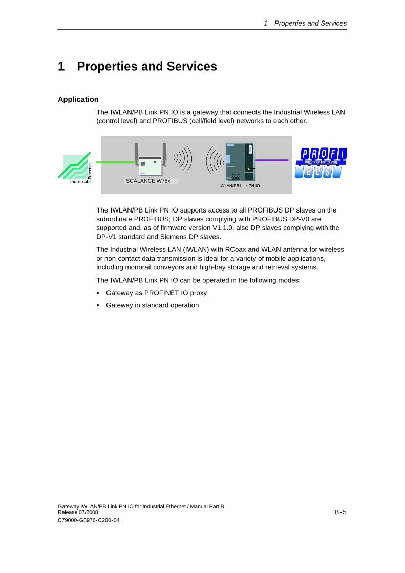
The IWLAN/PB Link PN IO is a gateway that connects the Industrial Wireless LAN(control level) and PROFIBUS (cell/field level) networks to each other.
SCALANCE W78x
The IWLAN/PB Link PN IO supports access to all PROFIBUS DP slaves on thesubordinate PROFIBUS; DP slaves complying with PROFIBUS DP-V0 aresupported and, as of firmware version V1.1.0, also DP slaves complying with theDP-V1 standard and Siemens DP slaves.
The Industrial Wireless LAN (IWLAN) with RCoax and WLAN antenna for wirelessor non-contact data transmission is ideal for a variety of mobile applications,including monorail conveyors and high-bay storage and retrieval systems.
The IWLAN/PB Link PN IO can be operated in the following modes:
Gateway as PROFINET IO proxy
Gateway in standard operation
1 Properties and Services
B-6Gateway IWLAN/PB Link PN IO for Industrial Ethernet / Manual Part B
Release 07/2008
C79000-G8976-C200-04
Gateway as PROFINET IO proxy
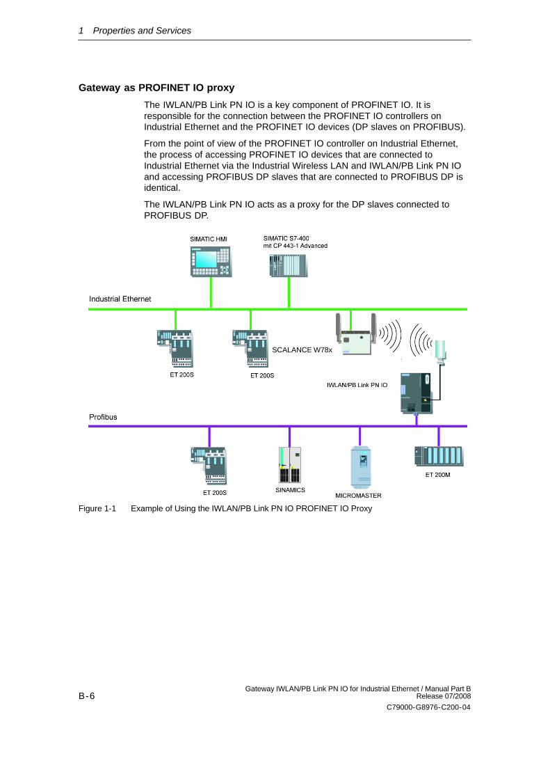
The IWLAN/PB Link PN IO is a key component of PROFINET IO. It isresponsible for the connection between the PROFINET IO controllers onIndustrial Ethernet and the PROFINET IO devices (DP slaves on PROFIBUS).
From the point of view of the PROFINET IO controller on Industrial Ethernet,the process of accessing PROFINET IO devices that are connected toIndustrial Ethernet via the Industrial Wireless LAN and IWLAN/PB Link PN IOand accessing PROFIBUS DP slaves that are connected to PROFIBUS DP isidentical.
The IWLAN/PB Link PN IO acts as a proxy for the DP slaves connected toPROFIBUS DP.
SCALANCE W78x
Figure 1-1 Example of Using the IWLAN/PB Link PN IO PROFINET IO Proxy
1 Properties and Services
B-7Gateway IWLAN/PB Link PN IO for Industrial Ethernet / Manual Part BRelease 07/2008
C79000-G8976-C200-04
Gateway in standard operation
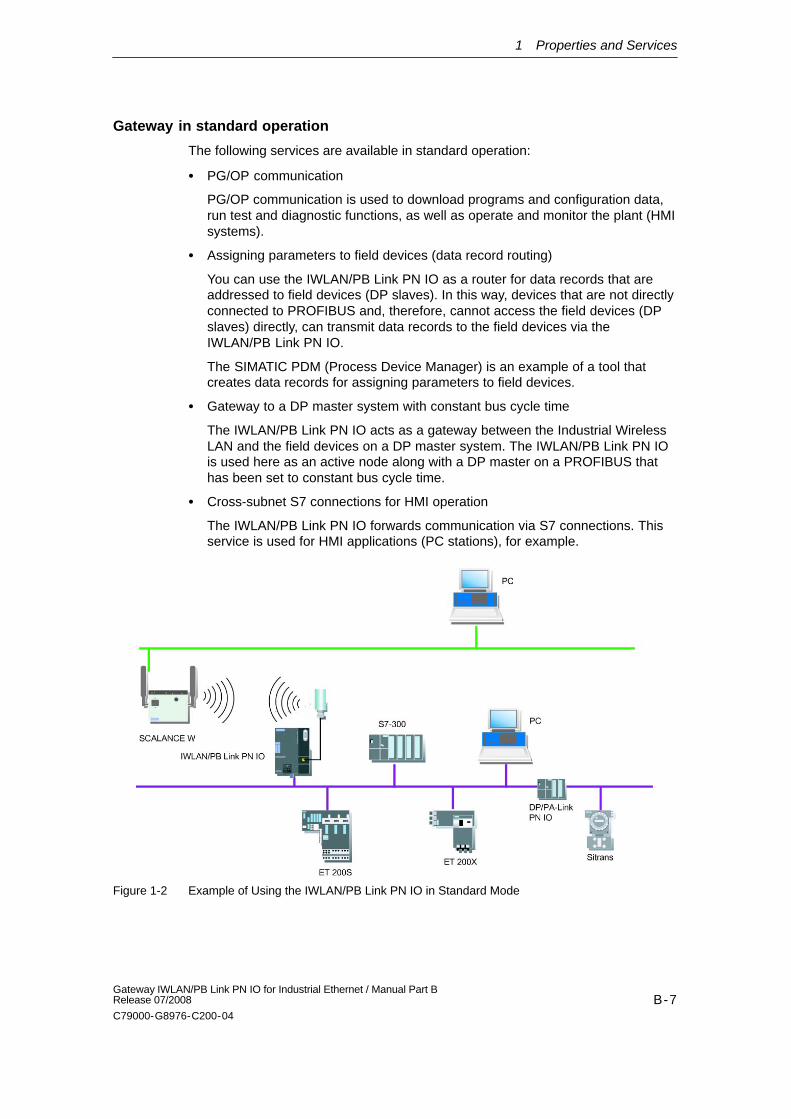
The following services are available in standard operation:
PG/OP communication
PG/OP communication is used to download programs and configuration data,run test and diagnostic functions, as well as operate and monitor the plant (HMIsystems).
Assigning parameters to field devices (data record routing)
You can use the IWLAN/PB Link PN IO as a router for data records that areaddressed to field devices (DP slaves). In this way, devices that are not directlyconnected to PROFIBUS and, therefore, cannot access the field devices (DPslaves) directly, can transmit data records to the field devices via theIWLAN/PB Link PN IO.
The SIMATIC PDM (Process Device Manager) is an example of a tool thatcreates data records for assigning parameters to field devices.
Gateway to a DP master system with constant bus cycle time
The IWLAN/PB Link PN IO acts as a gateway between the Industrial WirelessLAN and the field devices on a DP master system. The IWLAN/PB Link PN IOis used here as an active node along with a DP master on a PROFIBUS thathas been set to constant bus cycle time.
Cross-subnet S7 connections for HMI operation
The IWLAN/PB Link PN IO forwards communication via S7 connections. Thisservice is used for HMI applications (PC stations), for example.
SCALANCE W78x
Figure 1-2 Example of Using the IWLAN/PB Link PN IO in Standard Mode
1 Properties and Services
B-8Gateway IWLAN/PB Link PN IO for Industrial Ethernet / Manual Part B
Release 07/2008
C79000-G8976-C200-04
Gateway in mobile applications
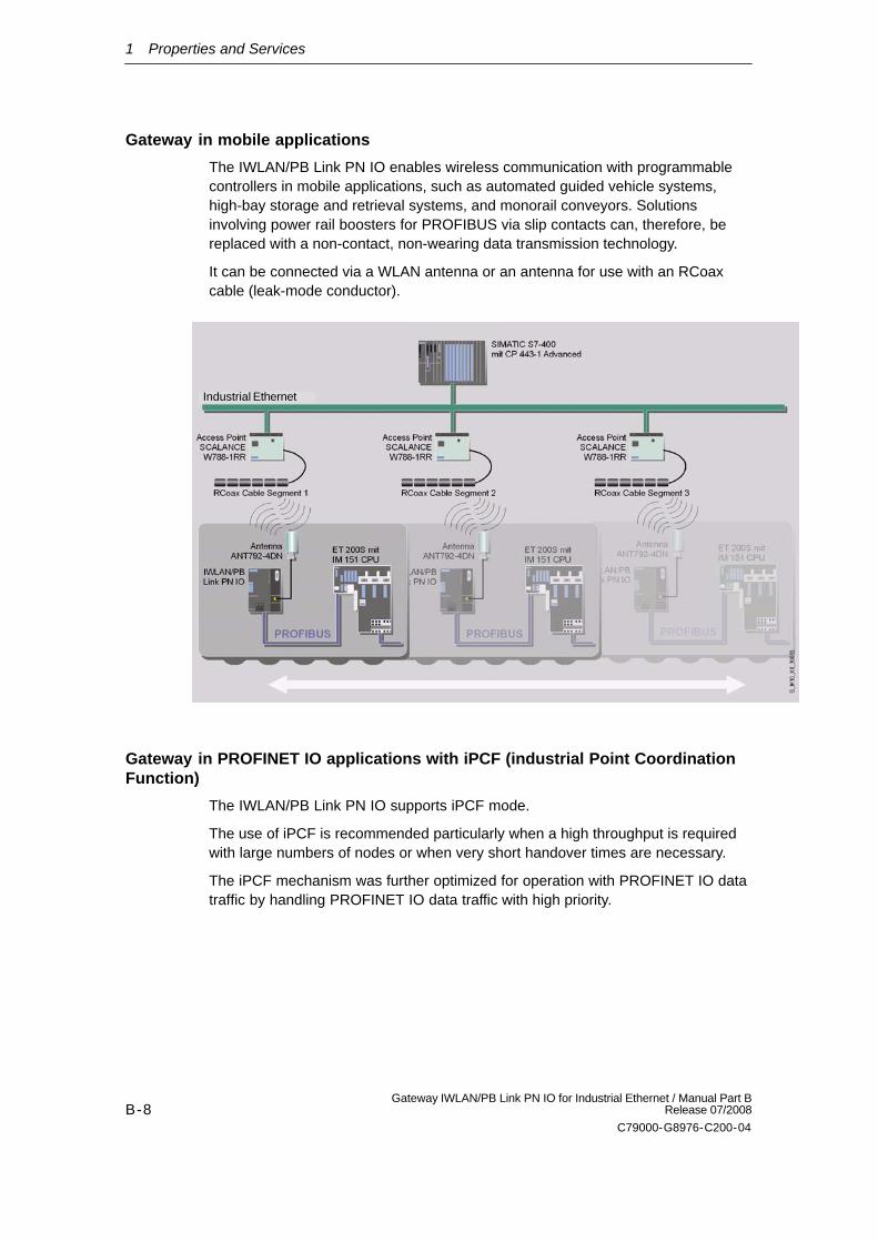
The IWLAN/PB Link PN IO enables wireless communication with programmablecontrollers in mobile applications, such as automated guided vehicle systems,high-bay storage and retrieval systems, and monorail conveyors. Solutionsinvolving power rail boosters for PROFIBUS via slip contacts can, therefore, bereplaced with a non-contact, non-wearing data transmission technology.
It can be connected via a WLAN antenna or an antenna for use with an RCoaxcable (leak-mode conductor).
Industrial Ethernet
Gateway in PROFINET IO applications with iPCF (industrial Point CoordinationFunction)
The IWLAN/PB Link PN IO supports iPCF mode.
The use of iPCF is recommended particularly when a high throughput is requiredwith large numbers of nodes or when very short handover times are necessary.
The iPCF mechanism was further optimized for operation with PROFINET IO datatraffic by handling PROFINET IO data traffic with high priority.
1 Properties and Services
B-9Gateway IWLAN/PB Link PN IO for Industrial Ethernet / Manual Part BRelease 07/2008
C79000-G8976-C200-04
Notice
For PROFINET IO communication, we recommend enabling the iPCF mode.
Stable PNIO communication is only possible when it is guaranteed that a WLANclient is in a cell with more than 60% signal strength at all times. This can bechecked by activating and deactivating the various segments.
This does not mean that the client needs to change when there is a signal strengthless than 60%. It is only necessary to make sure that a segment with adequatesignal strength would be available.
Note
You will find a detailed description of the commands of the Command LineInterface (CLI) in the Operating Instructions SCALANCE W788-xPRO/RR /SCALANCE W74x-1PRO/RR. This manual (file name:BA_SCALANCE-W788-xPRO-RR-W74x-1PRO-RR_0.pdf) is available on theCD that accompanies the IWLAN/PB Link PN IO or on the Internet at:
http://support.automation.siemens.com/WW/view/en/28529396
1 Properties and Services
B-10Gateway IWLAN/PB Link PN IO for Industrial Ethernet / Manual Part B
Release 07/2008
C79000-G8976-C200-04
Other properties and services
Industrial wireless LAN
IWLAN/PB Link PN IO provides a wireless interface (in compliance with IEEE802.11b/g/a/h.
Forwarding time messages (configurable option)
The IWLAN/PB Link PN IO can forward time messages received by a real-timetransmitter as follows:
- from Ethernet to PROFIBUS
- From PROFIBUS to Ethernet
If there is a time master on Industrial Ethernet, the IWLAN/PB Link PN IO thenreceives time messages for time stamping diagnostic buffer entries and processsignals.
Option: C-PLUG as exchangeable medium for the project engineering data
The IWLAN/PB Link PN IO allows the configuration data to be saved to aremovable memory medium (C-PLUG). In this way, a defective module cansimply be replaced by plugging the C-PLUG into the new module.
Option: PRESET-PLUG
The PRESET PLUG is a simple device for assigning a defined default setting toan IWLAN/PB Link PN IO and SCALANCE W devices.
WLAN Security Properties
- Supported authentication standards:
WPA, WPA-PSK, IEEE 802.1x, WPA2, WPA2-PSK
Note: WPA2 (Wi-Fi Protected Access 2) includes the further development ofWPA that implements the functions of the security standard IEEE 802.11i.
- Supported encryption methods:
WEP, AES, TKIP
Downloading firmware
IWLAN/PB Link PN IO supports updating of the firmware (FW) using thefirmware loader supplied with STEP 7 / NCM S7.
A firmware update can be downloaded at any time from the PC/PG via theEthernet port.
Configuration
You can configure the IWLAN/PB Link PN IO for all operating modes via IndustrialEthernet (recommended). If you use the device as a standard gateway, theconfiguration data can also be changed/supplied via PROFIBUS.
2 Structure
B-11Gateway IWLAN/PB Link PN IO for Industrial Ethernet / Manual Part BRelease 07/2008
C79000-G8976-C200-04
2 Structure
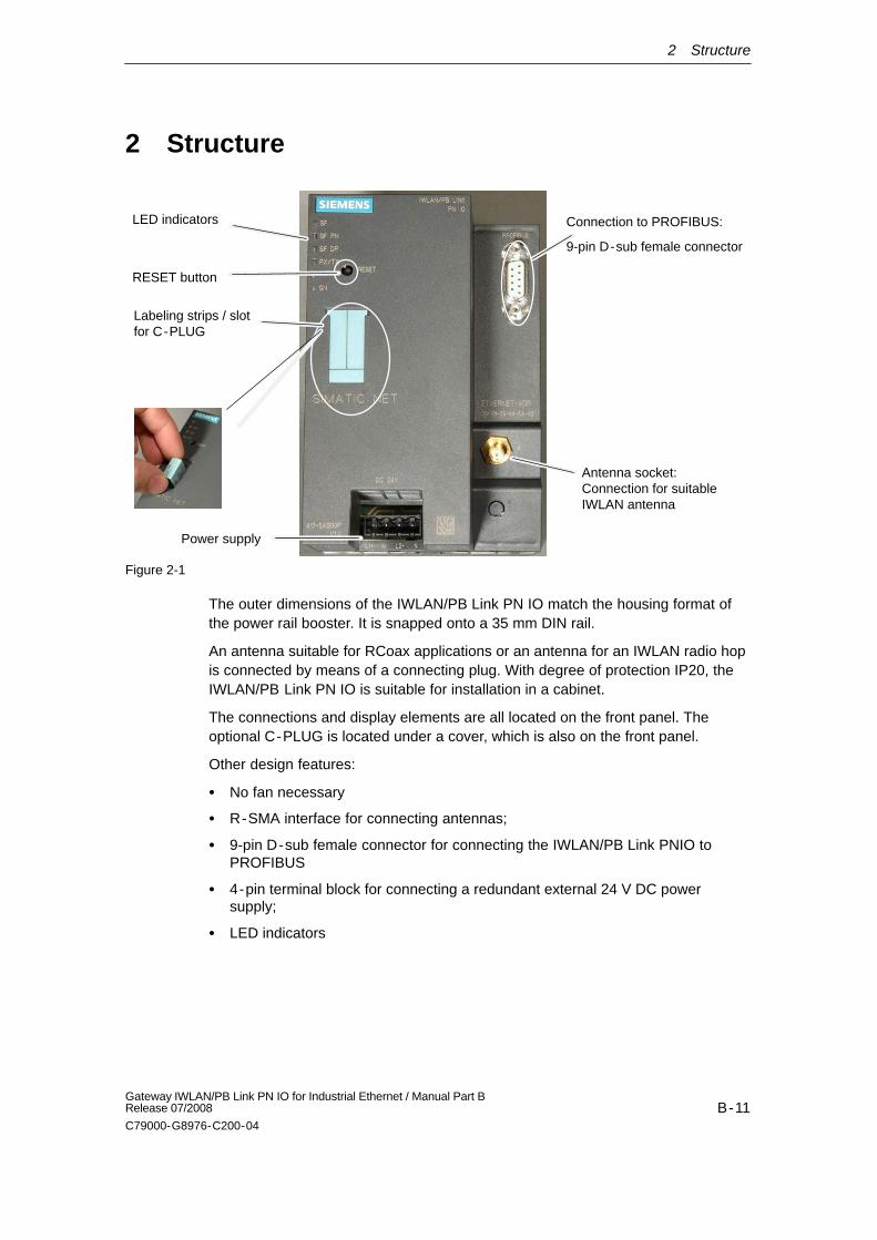
LED indicators
Antenna socket:Connection for suitableIWLAN antenna
Connection to PROFIBUS:
9-pin D-sub female connector
Labeling strips / slot for C-PLUG
Power supply
RESET button
Figure 2-1
The outer dimensions of the IWLAN/PB Link PN IO match the housing format ofthe power rail booster. It is snapped onto a 35 mm DIN rail.
An antenna suitable for RCoax applications or an antenna for an IWLAN radio hopis connected by means of a connecting plug. With degree of protection IP20, theIWLAN/PB Link PN IO is suitable for installation in a cabinet.
The connections and display elements are all located on the front panel. Theoptional C-PLUG is located under a cover, which is also on the front panel.
Other design features:
No fan necessary
R-SMA interface for connecting antennas;
9-pin D-sub female connector for connecting the IWLAN/PB Link PNIO toPROFIBUS
4-pin terminal block for connecting a redundant external 24 V DC powersupply;
LED indicators
3 Installation and Commissioning
B-12Gateway IWLAN/PB Link PN IO for Industrial Ethernet / Manual Part B
Release 07/2008
C79000-G8976-C200-04
3 Installation and Commissioning
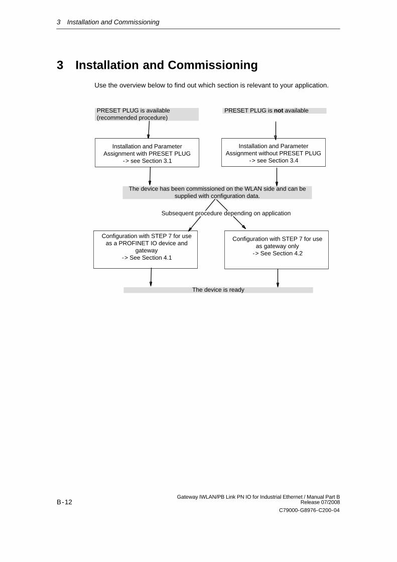
Use the overview below to find out which section is relevant to your application.
Installation and ParameterAssignment without PRESET PLUG
-> see Section 3.4
Configuration with STEP 7 for useas gateway only
-> See Section 4.2
Installation and ParameterAssignment with PRESET PLUG
-> see Section 3.1
The device has been commissioned on the WLAN side and can besupplied with configuration data.
Configuration with STEP 7 for useas a PROFINET IO device and
gateway-> See Section 4.1
PRESET PLUG is available(recommended procedure)
PRESET PLUG is not available
The device is ready
Subsequent procedure depending on application
3 Installation and Commissioning
B-13Gateway IWLAN/PB Link PN IO for Industrial Ethernet / Manual Part BRelease 07/2008
C79000-G8976-C200-04
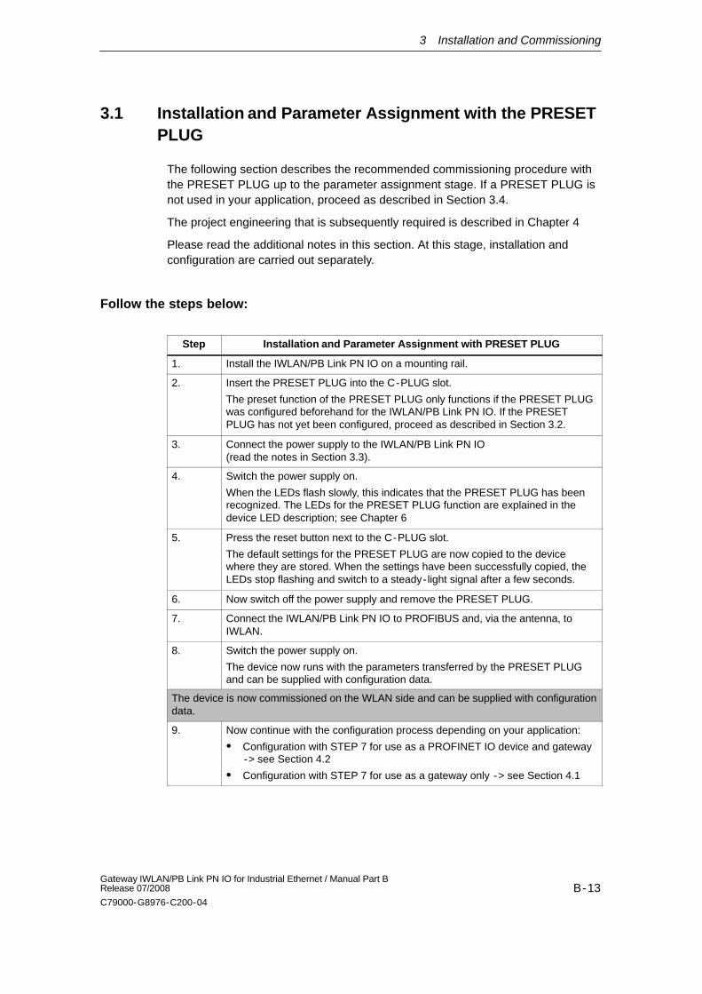
3.1 Installation and Parameter Assignment with the PRESETPLUG
The following section describes the recommended commissioning procedure withthe PRESET PLUG up to the parameter assignment stage. If a PRESET PLUG isnot used in your application, proceed as described in Section 3.4.
The project engineering that is subsequently required is described in Chapter 4
Please read the additional notes in this section. At this stage, installation andconfiguration are carried out separately.
Follow the steps below:
Step Installation and Parameter Assignment with PRESET PLUG
1. Install the IWLAN/PB Link PN IO on a mounting rail.
2. Insert the PRESET PLUG into the C-PLUG slot.
The preset function of the PRESET PLUG only functions if the PRESET PLUGwas configured beforehand for the IWLAN/PB Link PN IO. If the PRESETPLUG has not yet been configured, proceed as described in Section 3.2.
3. Connect the power supply to the IWLAN/PB Link PN IO (read the notes in Section 3.3).
4. Switch the power supply on.
When the LEDs flash slowly, this indicates that the PRESET PLUG has beenrecognized. The LEDs for the PRESET PLUG function are explained in thedevice LED description; see Chapter 6
5. Press the reset button next to the C-PLUG slot.
The default settings for the PRESET PLUG are now copied to the devicewhere they are stored. When the settings have been successfully copied, theLEDs stop flashing and switch to a steady-light signal after a few seconds.
6. Now switch off the power supply and remove the PRESET PLUG.
7. Connect the IWLAN/PB Link PN IO to PROFIBUS and, via the antenna, toIWLAN.
8. Switch the power supply on.
The device now runs with the parameters transferred by the PRESET PLUGand can be supplied with configuration data.
The device is now commissioned on the WLAN side and can be supplied with configurationdata.
9. Now continue with the configuration process depending on your application:
Configuration with STEP 7 for use as a PROFINET IO device and gateway-> see Section 4.2
Configuration with STEP 7 for use as a gateway only -> see Section 4.1
3 Installation and Commissioning
B-14Gateway IWLAN/PB Link PN IO for Industrial Ethernet / Manual Part B
Release 07/2008
C79000-G8976-C200-04
General notes
IP parameters and device-specific parameters are not changed
Using the PRESET PLUG prevents duplicate IP addresses by ensuring that theIP parameters are retained unchanged.
Other device-specific parameters also remain unchanged, including:
- System Contact
- System Name
- System Location
The WLAN interface is deactivated.
The WLAN device interface is deactivated when the PRESET PLUG isinserted. The device cannot be operated with the WLAN when the PRESETPLUG is inserted.
3 Installation and Commissioning
B-15Gateway IWLAN/PB Link PN IO for Industrial Ethernet / Manual Part BRelease 07/2008
C79000-G8976-C200-04
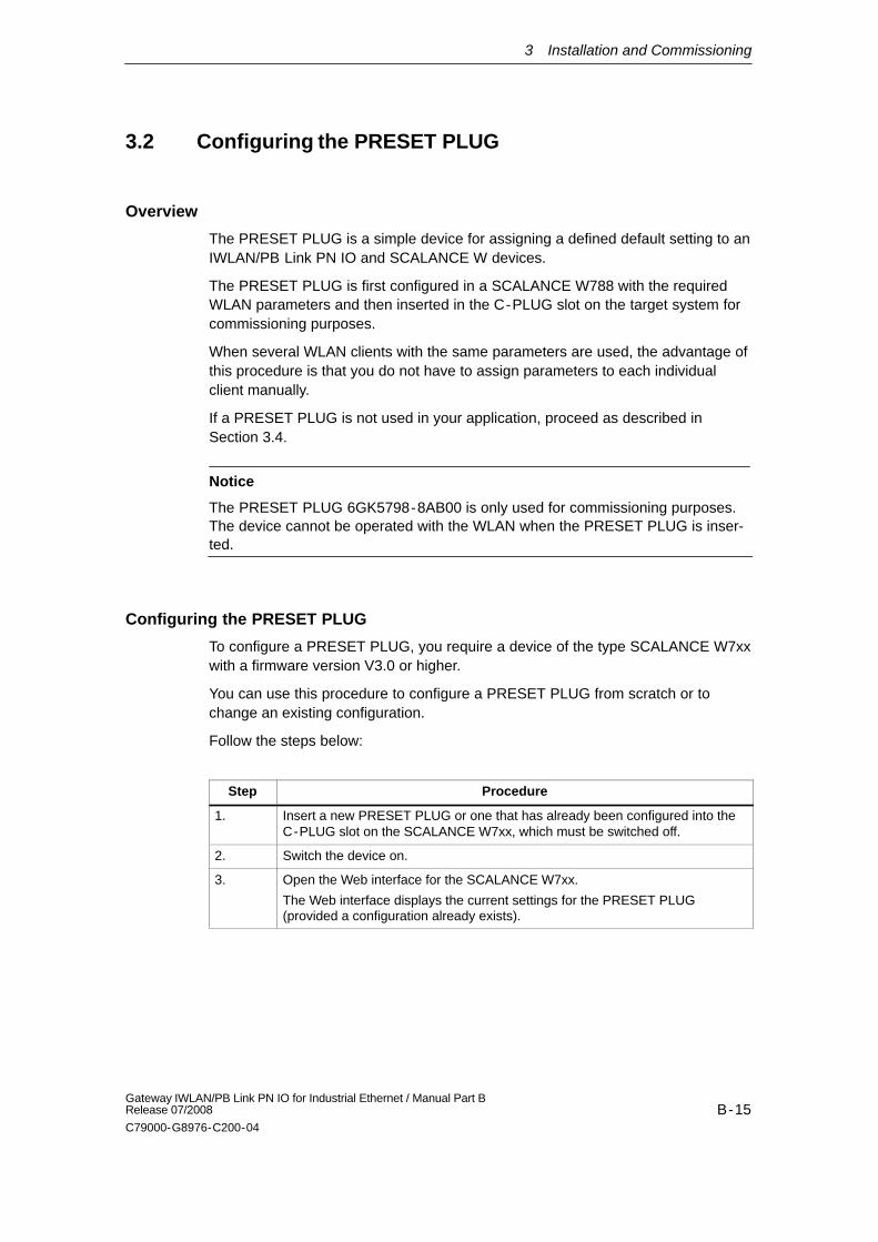
3.2 Configuring the PRESET PLUG
Overview
The PRESET PLUG is a simple device for assigning a defined default setting to anIWLAN/PB Link PN IO and SCALANCE W devices.
The PRESET PLUG is first configured in a SCALANCE W788 with the requiredWLAN parameters and then inserted in the C-PLUG slot on the target system forcommissioning purposes.
When several WLAN clients with the same parameters are used, the advantage ofthis procedure is that you do not have to assign parameters to each individualclient manually.
If a PRESET PLUG is not used in your application, proceed as described inSection 3.4.
Notice
The PRESET PLUG 6GK5798-8AB00 is only used for commissioning purposes.The device cannot be operated with the WLAN when the PRESET PLUG is inser-ted.
Configuring the PRESET PLUG
To configure a PRESET PLUG, you require a device of the type SCALANCE W7xxwith a firmware version V3.0 or higher.
You can use this procedure to configure a PRESET PLUG from scratch or tochange an existing configuration.
Follow the steps below:
Step Procedure
1. Insert a new PRESET PLUG or one that has already been configured into theC-PLUG slot on the SCALANCE W7xx, which must be switched off.
2. Switch the device on.
3. Open the Web interface for the SCALANCE W7xx.
The Web interface displays the current settings for the PRESET PLUG(provided a configuration already exists).
3 Installation and Commissioning
B-16Gateway IWLAN/PB Link PN IO for Industrial Ethernet / Manual Part B
Release 07/2008
C79000-G8976-C200-04
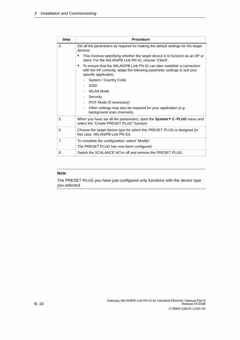
Step Procedure
4. Set all the parameters as required for making the default settings for the targetdevices:
This involves specifying whether the target device is to function as an AP orclient. For the IWLAN/PB Link PN IO, choose ”Client”.
To ensure that the IWLAN/PB Link PN IO can later establish a connectionwith the AP correctly, adapt the following parameter settings to suit yourspecific application:
- System / Country Code
- SSID
- WLAN Mode
- Security
- iPCF Mode (if necessary)
- Other settings may also be required for your application (e.g.background scan channels).
5. When you have set all the parameters, open the System C-PLUG menu andselect the ”Create PRESET PLUG” function.
6. Choose the target device type for which this PRESET PLUG is designed (inthis case: IWLAN/PB Link PN IO).
7. To complete the configuration, select ”Modify”.
The PRESET PLUG has now been configured.
8. Switch the SCALANCE W7xx off and remove the PRESET PLUG.
Note
The PRESET PLUG you have just configured only functions with the device typeyou selected.
3 Installation and Commissioning
B-17Gateway IWLAN/PB Link PN IO for Industrial Ethernet / Manual Part BRelease 07/2008
C79000-G8976-C200-04
3.3 Establishing the Connections
3.3.1 Important Notes
Notice
Important notes on installation and operation:
The module must be installed so that its upper and lower ventilation slits arenot covered, allowing adequate ventilation.
Note
The PROFIBUS can be connected while the power supply is on.
Notice
The requirements of EN61000-4-5, surge immunity test on power supply lines,are met only when using a Blitzductor VT AD 24V type no. 918 402 .
Manufacturer:DEHN+SÖHNE GmbH+Co.KG Hans Dehn Str.1 Postfach 1640 D-92306Neumarkt, Germany
!Warning
The IWLAN/PB Link PN IO product must be installed in an enclosure orswitchgear cabinet.
Where ATEX 100a (EN 50021) applies, this enclosure must meet at least IP54 incompliance with EN 60529.
WARNINGTHE DEVICE MAY ONLY BE CONNECTED TO THE POWER SUPPLY ORDISCONNECTED FROM IT WHEN THE RISK OF EXPLOSION CAN BEEXCLUDED WITH CERTAINTY.
Ground/chassis ground concept
The device is grounded over the mounting rail.
3 Installation and Commissioning
B-18Gateway IWLAN/PB Link PN IO for Industrial Ethernet / Manual Part B
Release 07/2008
C79000-G8976-C200-04
Module accessories
The accessories (including the power supply) required for connecting theIWLAN/PB Link PN IO to an Industrial Wireless LAN and PROFIBUS must beordered separately.
The optional C-PLUG can also be ordered separately.
For more detailed information and ordering data, refer to the Catalog IK PI.
3.3.2 PG/PC Connection
You can connect the PG when configuring the CP as follows:
Via Industrial Ethernet and WLAN interface (recommended)
Via PROFIBUS (for standard operation only)
Industrial Ethernet and WLAN interface (recommended)
Commissioning the device for the WLAN is described in detail in this chapter (3).When configuring on the PG, a distinction must be made between the followingmodes:
PROFINET IO use case
In this use case, the IWLAN/PB Link PN IO obtains its project engineering datafrom the controller. This means:
- Controller and Link must be connected over the WLAN;
- The Link must already have been assigned a device name with STEP 7 sothat the project engineering data can be downloaded.
Read the detailed description of project engineering in Section 4.1.
Standalone Mode
In this use case, the IWLAN/PB Link PN IO is configured and downloaded asan S7-300 station. This can take place as soon as you have assigned anEthernet address to the device with STEP 7. Read the detailed description ofproject engineering in Section 4.2.
PROFIBUS (for standard operation only)
The IWLAN/PB Link PN IO can be reached over the PROFIBUS interface. Youmust, however, first assign a PROFIBUS address in the project engineering.
3 Installation and Commissioning
B-19Gateway IWLAN/PB Link PN IO for Industrial Ethernet / Manual Part BRelease 07/2008
C79000-G8976-C200-04
3.3.3 Power Supply
!Warning
The IWLAN/PB Link PN IO is designed for operation with safety extra- low voltage(SELV). This means that only safety extra- low voltages (SELV) complying withIEC950/EN60950/ VDE0805 may be connected to the power supply terminals.
The power supply unit to supply the IWLAN/PB Link PN IO must comply with NECClass 2 (voltage range 20.4 - 28.8 V, current requirement 300 mA).
The device must only be supplied by a power supply unit that complies with therequirements of class 2 for power supply units of the ”National Electrical Code,Table 11 (b)”. If the power supply is installed redundantly (two separate powersupplies), the total power of both power supplies together must meet theserequirements.
Exceptions:
Supply by a SELV power source (complying with IEC 60950) or PELV powersource (complying with VDE 0100-410) without restricted power is alsopermitted as long as suitable fire prevention measures are taken by means of:
- installation in cabinet or suitable enclosure
- installation in suitably equipped, closed room
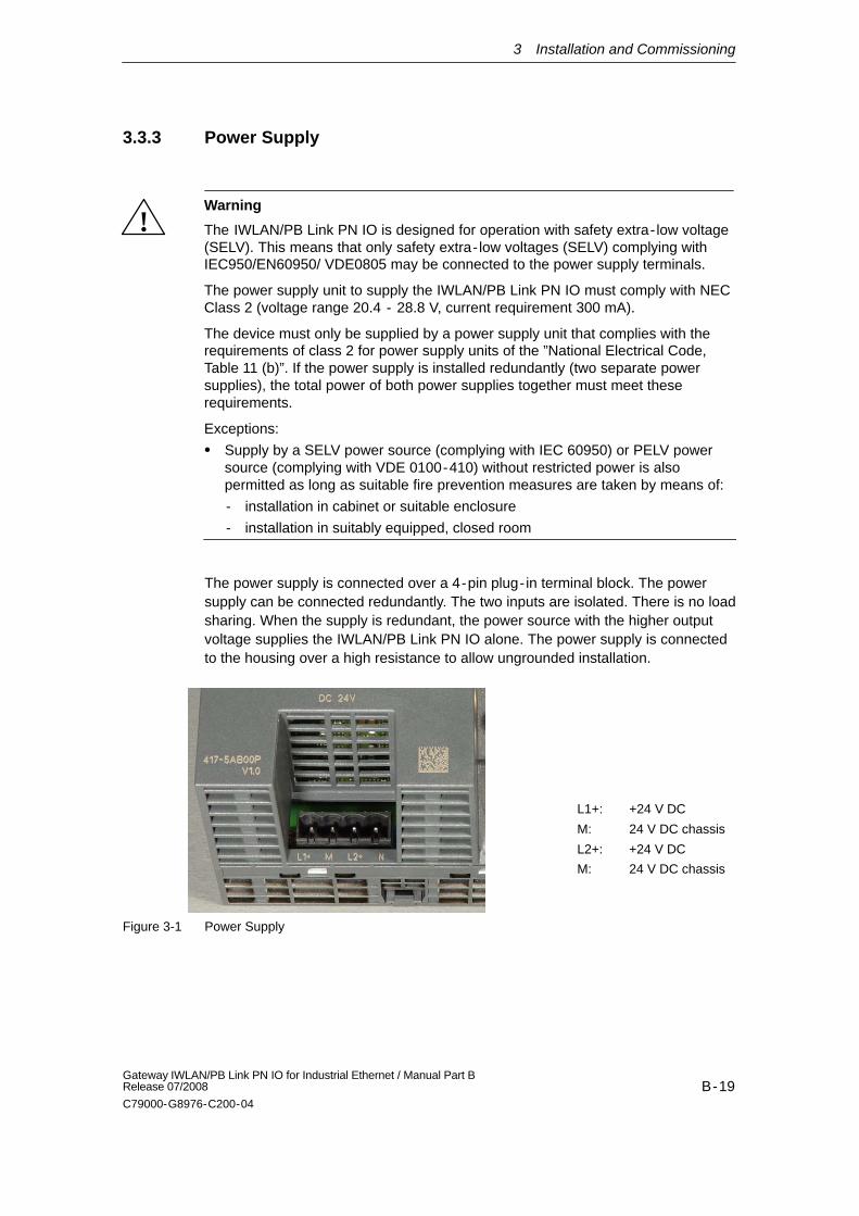
The power supply is connected over a 4-pin plug- in terminal block. The powersupply can be connected redundantly. The two inputs are isolated. There is no loadsharing. When the supply is redundant, the power source with the higher outputvoltage supplies the IWLAN/PB Link PN IO alone. The power supply is connectedto the housing over a high resistance to allow ungrounded installation.
L1+: +24 V DC
M: 24 V DC chassis
L2+: +24 V DC
M: 24 V DC chassis
Figure 3-1 Power Supply
3 Installation and Commissioning
B-20Gateway IWLAN/PB Link PN IO for Industrial Ethernet / Manual Part B
Release 07/2008
C79000-G8976-C200-04
3.4 Installation and Parameter Assignment without thePRESET PLUG
Overview
The PRESET PLUG is a simple device for assigning a defined default setting to anIWLAN/PB Link PN IO and SCALANCE W devices.
If a PRESET PLUG is not used in your application, proceed as described below toassign parameters for the IWLAN/PB Link PN IO.
Before carrying out the procedure described below, make sure that the device hasthe default settings as shipped. If this is not the case, use the RESET button torestore the factory settings (see Section 5.2.3)
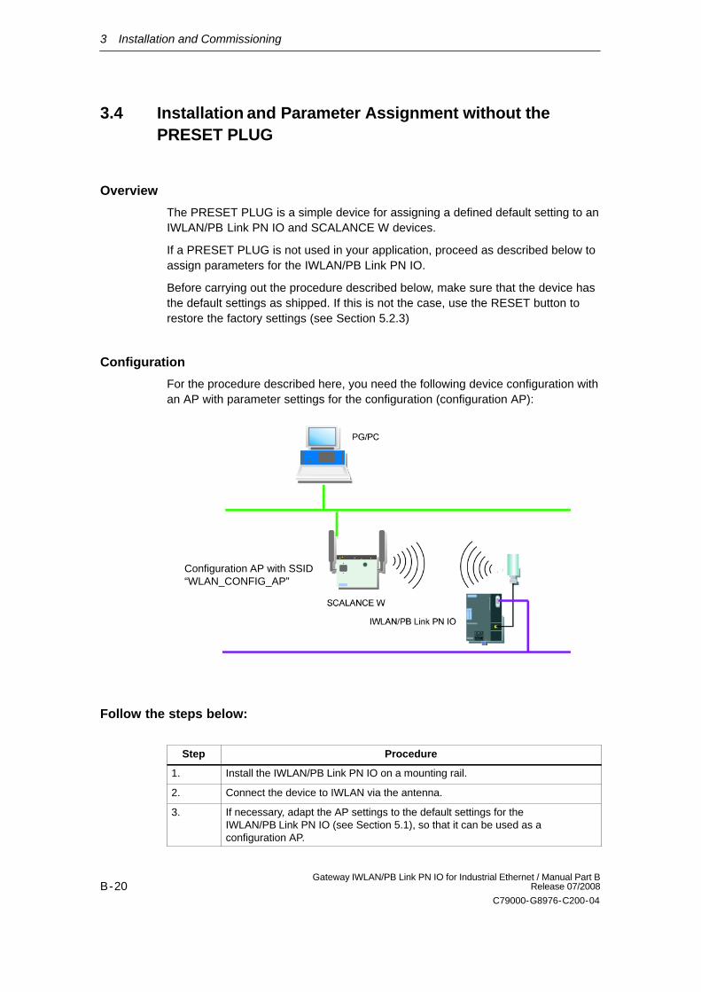
Configuration
For the procedure described here, you need the following device configuration withan AP with parameter settings for the configuration (configuration AP):
Configuration AP with SSID“WLAN_CONFIG_AP”
Follow the steps below:
Step Procedure
1. Install the IWLAN/PB Link PN IO on a mounting rail.
2. Connect the device to IWLAN via the antenna.
3. If necessary, adapt the AP settings to the default settings for theIWLAN/PB Link PN IO (see Section 5.1), so that it can be used as aconfiguration AP.
3 Installation and Commissioning
B-21Gateway IWLAN/PB Link PN IO for Industrial Ethernet / Manual Part BRelease 07/2008
C79000-G8976-C200-04
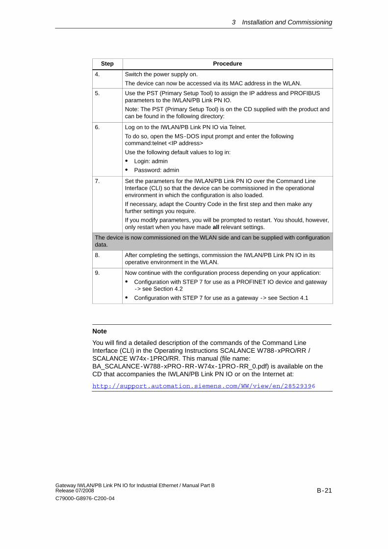
Step Procedure
4. Switch the power supply on.
The device can now be accessed via its MAC address in the WLAN.
5. Use the PST (Primary Setup Tool) to assign the IP address and PROFIBUSparameters to the IWLAN/PB Link PN IO.
Note: The PST (Primary Setup Tool) is on the CD supplied with the product andcan be found in the following directory:
6. Log on to the IWLAN/PB Link PN IO via Telnet.
To do so, open the MS-DOS input prompt and enter the followingcommand:telnet <IP address>
Use the following default values to log in:
Login: admin
Password: admin
7. Set the parameters for the IWLAN/PB Link PN IO over the Command LineInterface (CLI) so that the device can be commissioned in the operationalenvironment in which the configuration is also loaded.
If necessary, adapt the Country Code in the first step and then make anyfurther settings you require.
If you modify parameters, you will be prompted to restart. You should, however,only restart when you have made all relevant settings.
The device is now commissioned on the WLAN side and can be supplied with configurationdata.
8. After completing the settings, commission the IWLAN/PB Link PN IO in itsoperative environment in the WLAN.
9. Now continue with the configuration process depending on your application:
Configuration with STEP 7 for use as a PROFINET IO device and gateway-> see Section 4.2
Configuration with STEP 7 for use as a gateway -> see Section 4.1
Note
You will find a detailed description of the commands of the Command LineInterface (CLI) in the Operating Instructions SCALANCE W788-xPRO/RR /SCALANCE W74x-1PRO/RR. This manual (file name:BA_SCALANCE-W788-xPRO-RR-W74x-1PRO-RR_0.pdf) is available on theCD that accompanies the IWLAN/PB Link PN IO or on the Internet at:
http://support.automation.siemens.com/WW/view/en/28529396
3 Installation and Commissioning
B-22Gateway IWLAN/PB Link PN IO for Industrial Ethernet / Manual Part B
Release 07/2008
C79000-G8976-C200-04
3.5 C-PLUG (Configuration Plug)
C-PLUG removable memory medium as an alternative to flash memory
The IWLAN/PB Link PN IO has an internal flash memory for storing the projectengineering data. As an option, the device can be operated with a C-PLUG(configuration plug) removable memory medium.
The IWLAN/PB Link PN IO can be operated with or without a C-PLUG. Theexisting flash memory is then only used when no C-PLUG is inserted.
If a C-PLUG is inserted, the project engineering data is always stored on it. Thissimplifies replacement of modules. By simply exchanging the C-PLUG, all the datacan be transferred to the replacement module.
Response to an unknown or invalid C-PLUG
If a C-PLUG is inserted that does not have the correct format or valid data for theIWLAN/PB Link PN IO, the IWLAN/PB Link PN IO will not start up. Device status:System fault LED lit.
To ensure that you can access the IWLAN/PB Link PN IO via the WLAN interfacein this status, the WLAN parameters stored in the internal flash memory are used.
If you know this parameter, please format the C-PLUG with NCM diagnostics orreplace the C-PLUG with a C-PLUG with valid data.
If, however, you do not know this parameter and cannot establish a connection inthe WLAN, use the RESET button to run a ”reset to factory settings” with theC-PLUG inserted (see Section 5.2); you then operate with the default WLANparameters.
Notice
The C-PLUG may only be inserted or removed when the power is turned off!
3 Installation and Commissioning
B-23Gateway IWLAN/PB Link PN IO for Industrial Ethernet / Manual Part BRelease 07/2008
C79000-G8976-C200-04
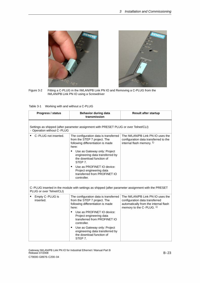
Figure 3-2 Fitting a C-PLUG in the IWLAN/PB Link PN IO and Removing a C-PLUG from theIWLAN/PB Link PN IO using a Screwdriver
Table 3-1 Working with and without a C-PLUG
Progress / status Behavior during datatransmission
Result after startup
Settings as shipped (after parameter assignment with PRESET PLUG or over Telnet/CLI) - Operation without C-PLUG
C-PLUG not inserted. The configuration data is transferredfrom the STEP 7 project. Thefollowing differentiation is madehere:
Use as Gateway only: Projectengineering data transferred bythe download function ofSTEP 7.
Use as PROFINET IO device:Project engineering datatransferred from PROFINET IOcontroller.
The IWLAN/PB Link PN IO uses theconfiguration data transferred to theinternal flash memory. 1)
C-PLUG inserted in the module with settings as shipped (after parameter assignment with the PRESETPLUG or over Telnet/CLI)
Empty C-PLUG isinserted.
The configuration data is transferredfrom the STEP 7 project. Thefollowing differentiation is madehere:
Use as PROFINET IO device:Project engineering datatransferred from PROFINET IOcontroller.
Use as Gateway only: Projectengineering data transferred bythe download function ofSTEP 7.
The IWLAN/PB Link PN IO uses theconfiguration data transferredautomatically from the internal flashmemory to the C-PLUG. 1)
3 Installation and Commissioning
B-24Gateway IWLAN/PB Link PN IO for Industrial Ethernet / Manual Part B
Release 07/2008
C79000-G8976-C200-04
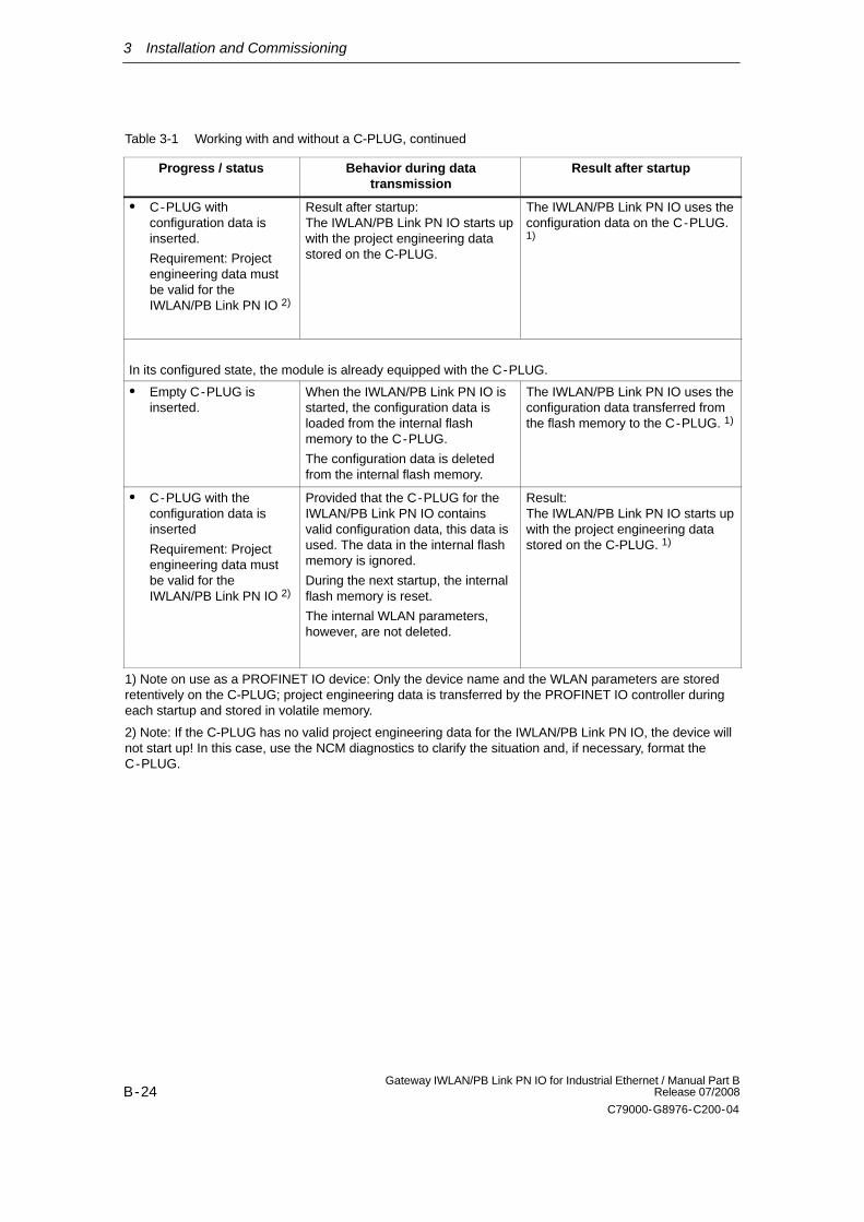
Table 3-1 Working with and without a C-PLUG, continued
Progress / status Result after startupBehavior during datatransmission
C-PLUG withconfiguration data isinserted.
Requirement: Projectengineering data mustbe valid for theIWLAN/PB Link PN IO 2)
Result after startup:The IWLAN/PB Link PN IO starts upwith the project engineering datastored on the C-PLUG.
The IWLAN/PB Link PN IO uses theconfiguration data on the C-PLUG.1)
In its configured state, the module is already equipped with the C-PLUG.
Empty C-PLUG isinserted.
When the IWLAN/PB Link PN IO isstarted, the configuration data isloaded from the internal flashmemory to the C-PLUG.
The configuration data is deletedfrom the internal flash memory.
The IWLAN/PB Link PN IO uses theconfiguration data transferred fromthe flash memory to the C-PLUG. 1)
C-PLUG with theconfiguration data isinserted
Requirement: Projectengineering data mustbe valid for theIWLAN/PB Link PN IO 2)
Provided that the C-PLUG for theIWLAN/PB Link PN IO containsvalid configuration data, this data isused. The data in the internal flashmemory is ignored.
During the next startup, the internalflash memory is reset.
The internal WLAN parameters,however, are not deleted.
Result:The IWLAN/PB Link PN IO starts upwith the project engineering datastored on the C-PLUG. 1)
1) Note on use as a PROFINET IO device: Only the device name and the WLAN parameters are storedretentively on the C-PLUG; project engineering data is transferred by the PROFINET IO controller duringeach startup and stored in volatile memory.
2) Note: If the C-PLUG has no valid project engineering data for the IWLAN/PB Link PN IO, the device willnot start up! In this case, use the NCM diagnostics to clarify the situation and, if necessary, format theC-PLUG.
4 Configuration with STEP 7
B-25Gateway IWLAN/PB Link PN IO for Industrial Ethernet / Manual Part BRelease 07/2008
C79000-G8976-C200-04
4 Configuration with STEP 7
To connect (initial addressing) and configure the IWLAN/PB Link PN IO, you needthe STEP 7/ NCM S7 configuration software (as of version V5.3 SP2 Hotfix 1.
Notice
If the hardware catalog of HW Config in your STEP 7 installation does not containthe IWLAN/PB Link PN IO component, you have to also install the hardware up-date in STEP 7 / HW Config.
The hardware update is on the CD supplied with the product and can be found inthe directory: software/HSP_1009
In STEP 7 / HW Config, choose:
Options Install Hardware Updates...
For information on how to continue, see the online help in STEP 7.
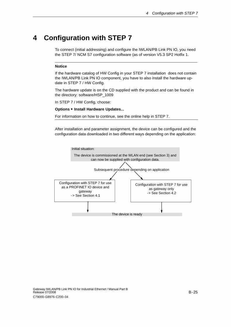
After installation and parameter assignment, the device can be configured and theconfiguration data downloaded in two different ways depending on the application:
Configuration with STEP 7 for useas gateway only
-> See Section 4.2
Initial situation:
The device is commissioned at the WLAN end (see Section 3) andcan now be supplied with configuration data.
Configuration with STEP 7 for useas a PROFINET IO device and
gateway-> See Section 4.1
The device is ready
Subsequent procedure depending on application
4 Configuration with STEP 7
B-26Gateway IWLAN/PB Link PN IO for Industrial Ethernet / Manual Part B
Release 07/2008
C79000-G8976-C200-04
4.1 Use as a PROFINET IO Device and as a Gateway
For this application, configure the IWLAN/PB Link PN IO as a PROFINET IOdevice with STEP 7/HW Config and assign a DP master system to theIWLAN/PB Link PN IO.
Load the configuration data to the PROFINET IO controller, which thenautomatically loads it to the IWLAN/PB Link PN IO.
Notice
You must always restore the factory settings when you switch the configured IW-LAN/PB Link PN IO operating mode. The device can only be operated as a PRO-FINET IO device or as a gateway.
4.1.1 Configuring the Properties with STEP 7
To assign address information and further parameters to theIWLAN/PB Link PN IO, you have to generate a loadable database (configuration)in STEP 7.
Follow the steps below
Step Configuring the IWLAN/PB Link PN IO as a PROFINET IO device withSTEP 7/HW Config
1. Use an existing STEP 7 project in which you have already created a PROFINET IOcontroller (e.g. an S7-400 station with a CP 443-1 Advanced).
2. Open HW Config by double-clicking the station you created .
3. Take the device type gateway IWLAN/PB Link PN IO from the hardware catalog underPROFINET IO and add this as an IO device on the PN IO system of the IO controller.
An IP address for the PROFINET IO system interface is determined automatically here.STEP 7 also assigns a device number to the IWLAN/PB Link PN IO. It chooses the highestfree device number in the current PROFINET IO system.
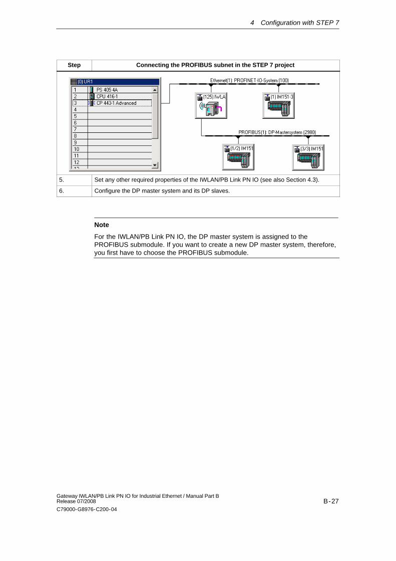
Step Connecting the PROFIBUS subnet in the STEP 7 project
4. Once you have transferred the IWLAN/PB Link PN IO from the hardware catalog, you areprompted to network the IWLAN/PB Link PN IO to the PROFIBUS interface.
If you have not yet created the required subnets, you can do this now by selecting therelevant entry. This creates a DP master system.
Results:
In HWConfig, the IWLAN/PB Link PN IO is created as a PROFINET IO device with a DP master system.
4 Configuration with STEP 7
B-27Gateway IWLAN/PB Link PN IO for Industrial Ethernet / Manual Part BRelease 07/2008
C79000-G8976-C200-04
Step Connecting the PROFIBUS subnet in the STEP 7 project
5. Set any other required properties of the IWLAN/PB Link PN IO (see also Section 4.3).
6. Configure the DP master system and its DP slaves.
Note
For the IWLAN/PB Link PN IO, the DP master system is assigned to thePROFIBUS submodule. If you want to create a new DP master system, therefore,you first have to choose the PROFIBUS submodule.
4 Configuration with STEP 7
B-28Gateway IWLAN/PB Link PN IO for Industrial Ethernet / Manual Part B
Release 07/2008
C79000-G8976-C200-04
4.1.2 Update Time for the PROFINET IO System
You can display and set the parameters described below in the properties dialogbox for the PROFINET IO system in HW Config.
Setting the update time
Update times can only be set in certain intervals. STEP 7 determines the relevantvalues on the basis of the properties of the IO devices involved.
If you change the basic hardware configuration, for example, add new IO devices,the update time can change. The next time you open the dialog, a messageinforms you that the update time has changed.
The default value for the update time is calculated automatically depending on themaximum number of links on an IWLAN segment (or AP).
Notice
Note that the update time you choose for the SCALANCE W788-RR must be iden-tical to the setting described here for the IWLAN/PB Link PN IO in the STEP 7configuration.
Set the update time over the CLI in the following menu: “ifeature ipcf PN IOUpdate Time
Selection of channels to be scanned
The minimum selectable update time is decided by the number of WLAN clients onan access point in the configuration in STEP 7.
To keep the proportion of cycle time required for scanning channels to a minimumwhen roaming, we recommend that you use the “Background scan channels”setting. This restricts the number of channels on which the IWLAN/PB Link PN IOscans for a channel.
To use this, select the following settings in the “Interfaces wlan1 Advanced”menu:
Background scan channel select -> activates the background scan
Background scan channels -> selection of channels to be scanned
This optimizes the roaming characteristics in terms of time.
4 Configuration with STEP 7
B-29Gateway IWLAN/PB Link PN IO for Industrial Ethernet / Manual Part BRelease 07/2008
C79000-G8976-C200-04
Optimizing the update time
You can optimize the update time by specifying the maximum number of links inyour system on the ”IWLAN Parameters” tab.
Notice
If the update time you choose is too short or if the IWLAN segment has more linksthan you specified on the ”IWLAN Parameters” tab, this may cause the connectionto be interrupted. For this reason, you are advised to retain the default settings.
When optimizing the update time, you must take into account the following pointsto ensure stable communication:
Case a: your system is operated in a single wireless segment; in other words,the clients (IWLAN/PB links, SCALANCE W74x) do not need to supportroaming to another wireless segment.
In this case, update times of >=8 ms are supported.
Optimum wireless conditions without roaming: update times of 4 ms are onlypossible under optimum wireless conditions and when the cell has just oneclient.
Case b: your system is operated with two wireless segments on two differentchannels.
In this case, update times of >=16 ms are also supported.
Case c: your system is operated with more than one wireless segment andmore than two channels. The clients also switch between the segments (roam).
In this case, the PN IO update time should be higher than 16 ms.
Notice
You are strongly advised to check the local radio conditions before commissioning.
Note
You will find a detailed description of the commands of the Command LineInterface (CLI) in the Operating Instructions SCALANCE W788-xPRO/RR /SCALANCE W74x-1PRO/RR. This manual (file name:BA_SCALANCE-W788-xPRO-RR-W74x-1PRO-RR_0.pdf) is available on theCD that accompanies the IWLAN/PB Link PN IO or on the Internet at:
http://support.automation.siemens.com/WW/view/en/28529396
4 Configuration with STEP 7
B-30Gateway IWLAN/PB Link PN IO for Industrial Ethernet / Manual Part B
Release 07/2008
C79000-G8976-C200-04
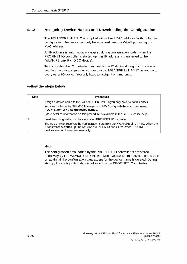
4.1.3 Assigning Device Names and Downloading the Configuration
The IWLAN/PB Link PN IO is supplied with a fixed MAC address. Without furtherconfiguration, the device can only be accessed over the WLAN port using thisMAC address.
An IP address is automatically assigned during configuration. Later when thePROFINET IO controller is started up, this IP address is transferred to theIWLAN/PB Link PN IO (IO device).
To ensure that the IO controller can identify the IO device during this procedure,you first have to assign a device name to the IWLAN/PB Link PN IO as you do toevery other IO device. You only have to assign the name once.
Follow the steps below
Step Procedure
1. Assign a device name to the IWLAN/PB Link PN IO (you only have to do this once).
You can do this in the SIMATIC Manager or in HW Config with the menu command PLC Ethernet Assign device name...
(More detailed information on this procedure is available in the STEP 7 online help.)
2. Load the configuration for the associated PROFINET IO controller.
The IO controller receives the configuration data from the IWLAN/PB Link PN IO. When theIO controller is started up, the IWLAN/PB Link PN IO and all the other PROFINET IOdevices are configured automatically.
Note
The configuration data loaded by the PROFINET IO controller is not storedretentively by the IWLAN/PB Link PN IO. When you switch the device off and thenon again, all the configuration data except for the device name is deleted. Duringstartup, the configuration data is reloaded by the PROFINET IO controller.
4 Configuration with STEP 7
B-31Gateway IWLAN/PB Link PN IO for Industrial Ethernet / Manual Part BRelease 07/2008
C79000-G8976-C200-04
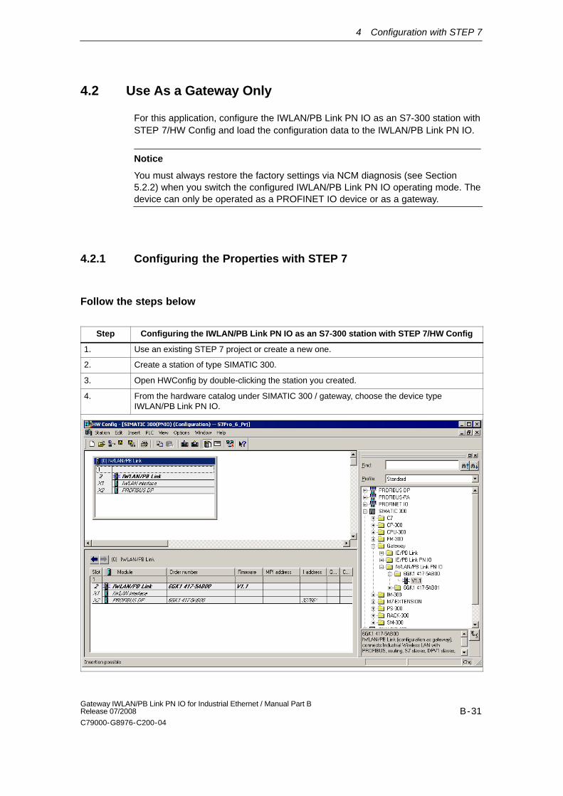
4.2 Use As a Gateway Only
For this application, configure the IWLAN/PB Link PN IO as an S7-300 station withSTEP 7/HW Config and load the configuration data to the IWLAN/PB Link PN IO.
Notice
You must always restore the factory settings via NCM diagnosis (see Section5.2.2) when you switch the configured IWLAN/PB Link PN IO operating mode. Thedevice can only be operated as a PROFINET IO device or as a gateway.
4.2.1 Configuring the Properties with STEP 7
Follow the steps below
Step Configuring the IWLAN/PB Link PN IO as an S7-300 station with STEP 7/HW Config
1. Use an existing STEP 7 project or create a new one.
2. Create a station of type SIMATIC 300.
3. Open HWConfig by double-clicking the station you created.
4. From the hardware catalog under SIMATIC 300 / gateway, choose the device typeIWLAN/PB Link PN IO.
4 Configuration with STEP 7
B-32Gateway IWLAN/PB Link PN IO for Industrial Ethernet / Manual Part B
Release 07/2008
C79000-G8976-C200-04
Step Connect the IWLAN/PB Link PN IO to the Ethernet and PROFIBUS subnet in theSTEP 7 project
5. Once you have copied the IWLAN/PB Link PN IO from the hardware catalog, you areprompted to network the IWLAN/PB Link PN IO on the Ethernet interface and then on thePROFIBUS interface.
If you have not yet created the required subnets, you can do this now by selecting therelevant entry.
Result:You have created the IWLAN/PB Link PN IO component with a basic module and theEthernet and PROFIBUS submodules in the S7-300 station in HW Config.
6. Set any other properties of the IWLAN/PB Link PN IO. For more information about this, seeSections 4.3.1 to 4.3.3.
4.2.2 Assigning the IP Address and Loading the Configuration
The IWLAN/PB Link PN IO is supplied with a fixed MAC address. Without furtherconfiguration, the device can only be accessed via the WLAN connection using thisMAC address.
Step Commissioning the IWLAN/PB Link PN IO
7. Assign an IP address to the IWLAN/PB Link PN IO provided you have not already done thisin the SIMATIC Manager independently of the configuration steps described here.
To do so, choose the following menu command in HW Config PLC Ethernet Assign Ethernet Address...
8. Load the database (configuration) from STEP 7 to the IWLAN/PB Link PN IO.
The initial load process must be carried out from the Industrial Wireless LAN via the TCP/IPinterface. Subsequent load processes can be carried out from PROFIBUS or the IndustrialWireless LAN via the TCP/IP interface depending on the PG connection.
Notice
Note that the IWLAN/PB Link PN IO is a special configuration component thatalready contains all the required station components. For this reason, you cannotplace any other component (e.g. rack or modules) next to the IWLAN/PBLink PN IO.

4 Configuration with STEP 7
B-33Gateway IWLAN/PB Link PN IO for Industrial Ethernet / Manual Part BRelease 07/2008
C79000-G8976-C200-04
4.3 Parameters in the Properties Dialog Box for IWLAN/PB Link PN IO
You can set the other IWLAN/PB Link PN IO properties in HWConfig or via thecomponent view in NetPro (with gateway operation only).
4.3.1 Setting the Properties in the Basic Module
Opening the properties dialog
Selection option (example used here:in NetPro for operation as agateway):
After selecting the basic module andopening the object properties, youcan make the following settings:
“General” tab
Here, you can enter general information such as a technological name to beused for component management in the STEP 7 project.
“Options” tab
- Time-of-day synchronization
Here, you can set whether the IWLAN/PB Link PN IO is to forward timemessages from a real-time transmitter. Selectable directions: fromPROFIBUS to Ethernet or from Ethernet to PROFIBUS.
- Assigning parameters to field devices (data record routing)
Here, you can decide whether or not the device is to support data recordrouting for assigning parameters to field devices. As default, the option isactivated.
“Device number” tab (only with operation as PROFINET IO device)
The DP slaves are addressed as an IO device from the PROFINET IOcontroller using the PROFINET IO device number. ”Device number” tab Youcan display the device numbers of the DP slaves, which are assignedautomatically. You can change the device numbers.
4 Configuration with STEP 7
B-34Gateway IWLAN/PB Link PN IO for Industrial Ethernet / Manual Part B
Release 07/2008
C79000-G8976-C200-04
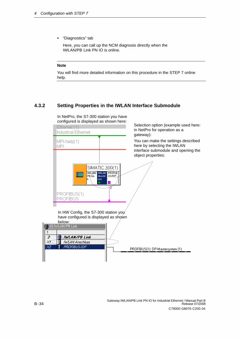
“Diagnostics” tab
Here, you can call up the NCM diagnosis directly when theIWLAN/PB Link PN IO is online.
Note
You will find more detailed information on this procedure in the STEP 7 onlinehelp.
4.3.2 Setting Properties in the IWLAN Interface Submodule
In NetPro, the S7-300 station you haveconfigured is displayed as shown here:
In HW Config, the S7-300 station youhave configured is displayed as shownbelow:
Selection option (example used here:in NetPro for operation as agateway):
You can make the settings describedhere by selecting the IWLANinterface submodule and opening theobject properties:
4 Configuration with STEP 7
B-35Gateway IWLAN/PB Link PN IO for Industrial Ethernet / Manual Part BRelease 07/2008
C79000-G8976-C200-04
These properties can be configured:
“General” tab
Here, you can enter general information to be used for component managementin the STEP 7 project. You can also set parameters for the interface to Ind.Ethernet.
Note
You will find more detailed information on this procedure in the STEP 7 onlinehelp.
4 Configuration with STEP 7
B-36Gateway IWLAN/PB Link PN IO for Industrial Ethernet / Manual Part B
Release 07/2008
C79000-G8976-C200-04
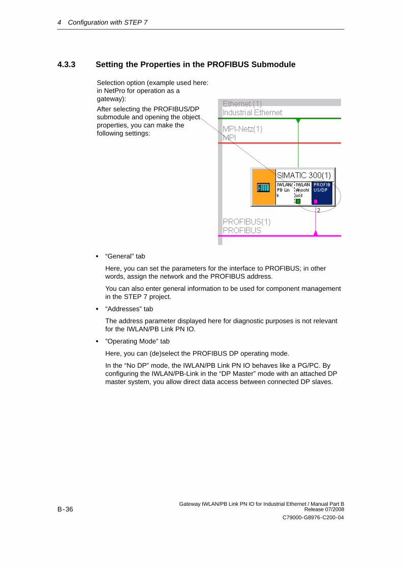
4.3.3 Setting the Properties in the PROFIBUS Submodule
Selection option (example used here:in NetPro for operation as agateway):
After selecting the PROFIBUS/DPsubmodule and opening the objectproperties, you can make thefollowing settings:
“General” tab
Here, you can set the parameters for the interface to PROFIBUS; in otherwords, assign the network and the PROFIBUS address.
You can also enter general information to be used for component managementin the STEP 7 project.
“Addresses” tab
The address parameter displayed here for diagnostic purposes is not relevantfor the IWLAN/PB Link PN IO.
”Operating Mode” tab
Here, you can (de)select the PROFIBUS DP operating mode.
In the “No DP” mode, the IWLAN/PB Link PN IO behaves like a PG/PC. Byconfiguring the IWLAN/PB-Link in the “DP Master” mode with an attached DPmaster system, you allow direct data access between connected DP slaves.
5 Restoring the Standard Settings
B-37Gateway IWLAN/PB Link PN IO for Industrial Ethernet / Manual Part BRelease 07/2008
C79000-G8976-C200-04
5 Restoring the Standard Settings
5.1 WLAN Settings as Shipped (Default Status)
When shipped, the IWLAN/PB Link PN IO is configured so that it uses an AP(access point) to connect to the SSID ”WLAN_CONFIG_AP” after startup.
Note: The configuration AP must be operated as follows in 802.11g mode:
Country code: Germany
As Open System (Security)
Without iPCF 1)
Note
You will find a detailed description of the commands of the Command LineInterface (CLI) in the Operating Instructions SCALANCE W788-xPRO/RR /SCALANCE W74x-1PRO/RR. This manual (file name:BA_SCALANCE-W788-xPRO-RR-W74x-1PRO-RR_0.pdf) is available on theCD that accompanies the IWLAN/PB Link PN IO or on the Internet at:
http://support.automation.siemens.com/WW/view/en/28529396
Parameter assignment without the PRESET PLUG using the Primary Setup Tooland CLI
The behavior in the default status as shipped allows an IP address to be assignedto the device by means of STEP 7 or the PST (Primary Setup Tool) after which itcan be assigned parameters by means of remote configuration with Telnet and theCommand Line Interface (CLI).
Note
The PST (Primary Setup Tool) is on the CD supplied with the product and can befound in the directory: software/PST
1) iPCF - industrial Point Coordination Function ensures that the entire data traffic of a wireless cell iscontrolled by the access point. This allows collisions to be avoided even with large numbers of nodes andoptimizes the throughput. iPCF also allows fast roaming.
5 Restoring the Standard Settings
B-38Gateway IWLAN/PB Link PN IO for Industrial Ethernet / Manual Part B
Release 07/2008
C79000-G8976-C200-04
5.2 Memory Reset or Resetting to Factory Settings
A three-step function is available for carrying out a memory reset on theIWLAN/PB Link PN IO:
Carry out the memory reset
Restore the factory settings via NCM diagnosis (WLAN parameters areretained)
Restore the factory settings via the RESET button (WLAN parameters arereset)
Notice
You must always reset to the factory settings using NCM diagnostics (see Section5.2.2) when you change the configured IWLAN/PB Link PN IO operating mode.The device can be operated as a PROFINET IO device or as a gateway only.
5.2.1 Memory Reset
Result / effect:
After a memory reset, the IWLAN/PB Link PN IO has the following status:
- All the configuration data has been deleted
- All connections to the device have been terminated
- The retentive parameters (for example, IP address and device name) areretained.
How to reset memory
The functions for carrying out a memory reset can be triggered from STEP 7. Youhave two options:
In STEP 7/HW Config with PLC Clear/Reset
or
In STEP 7 / NCM Diagnostics with Operating Mode Clear/Reset Module
5 Restoring the Standard Settings
B-39Gateway IWLAN/PB Link PN IO for Industrial Ethernet / Manual Part BRelease 07/2008
C79000-G8976-C200-04
5.2.2 Resetting to the Factory Settings using NCM Diagnostics -(WLAN parameters are retained)
Result / effect:
Once the factory settings have been restored, the IWLAN/PB Link PN IO stillretains the default MAC address (as shipped). The device name and the IPaddress are deleted.
The entire content of the optional C-PLUG is deleted. When the module is nextstarted up, the C-PLUG is initialized as a data record of type IWLAN/PB Link PNIO.
The set IWLAN parameters are retained, which means that the device remainsconnected to the AP.
How to carry out the function
For the diagnostic object IWLAN/PB Link PN IO, select the following menucommand in NCM diagnostics:
Operating Mode Reset to factory settings
5.2.3 Resetting to Factory Settings with the RESET Button - WLANparameters are reset)
Result / effect:
Once the factory settings have been restored, the IWLAN/PB Link PN IO stillretains the default MAC address (as shipped). The device name and the IPaddress are deleted.
The entire content of the optional C-PLUG is deleted. When the module is nextstarted up, the C-PLUG is initialized as a data record of type IWLAN/PB Link PNIO.
The set IWLAN parameters are also deleted and reset to the default values (seeSection 5.1)
How to carry out the function
Via the Reset button:
5 Restoring the Standard Settings
B-40Gateway IWLAN/PB Link PN IO for Industrial Ethernet / Manual Part B
Release 07/2008
C79000-G8976-C200-04
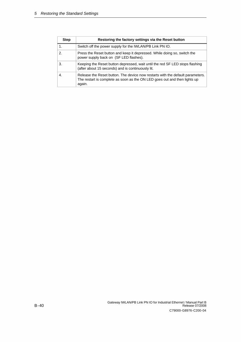
Step Restoring the factory settings via the Reset button
1. Switch off the power supply for the IWLAN/PB Link PN IO.
2. Press the Reset button and keep it depressed. While doing so, switch thepower supply back on (SF LED flashes).
3. Keeping the Reset button depressed, wait until the red SF LED stops flashing(after about 15 seconds) and is continuously lit.
4. Release the Reset button. The device now restarts with the default parameters.The restart is complete as soon as the ON LED goes out and then lights upagain.
6 LEDs
B-41Gateway IWLAN/PB Link PN IO for Industrial Ethernet / Manual Part BRelease 07/2008
C79000-G8976-C200-04
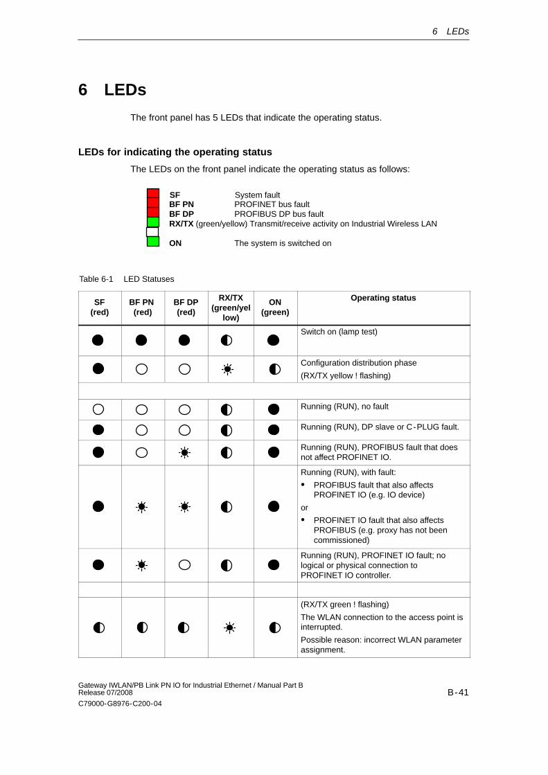
6 LEDs
The front panel has 5 LEDs that indicate the operating status.
LEDs for indicating the operating status
The LEDs on the front panel indicate the operating status as follows:
SF System fault
BF DP PROFIBUS DP bus faultRX/TX (green/yellow) Transmit/receive activity on Industrial Wireless LAN
ON The system is switched on
BF PN PROFINET bus fault
Table 6-1 LED Statuses
SF(red)
BF PN (red)
BF DP(red)
RX/TX(green/yel
low)
ON(green)
Operating status
Switch on (lamp test)
Configuration distribution phase
(RX/TX yellow ! flashing)
Running (RUN), no fault
Running (RUN), DP slave or C-PLUG fault.
Running (RUN), PROFIBUS fault that doesnot affect PROFINET IO.
Running (RUN), with fault:
PROFIBUS fault that also affectsPROFINET IO (e.g. IO device)
or
PROFINET IO fault that also affectsPROFIBUS (e.g. proxy has not beencommissioned)
Running (RUN), PROFINET IO fault; nological or physical connection toPROFINET IO controller.
(RX/TX green ! flashing)
The WLAN connection to the access point isinterrupted.
Possible reason: incorrect WLAN parameterassignment.
6 LEDs
B-42Gateway IWLAN/PB Link PN IO for Industrial Ethernet / Manual Part B
Release 07/2008
C79000-G8976-C200-04
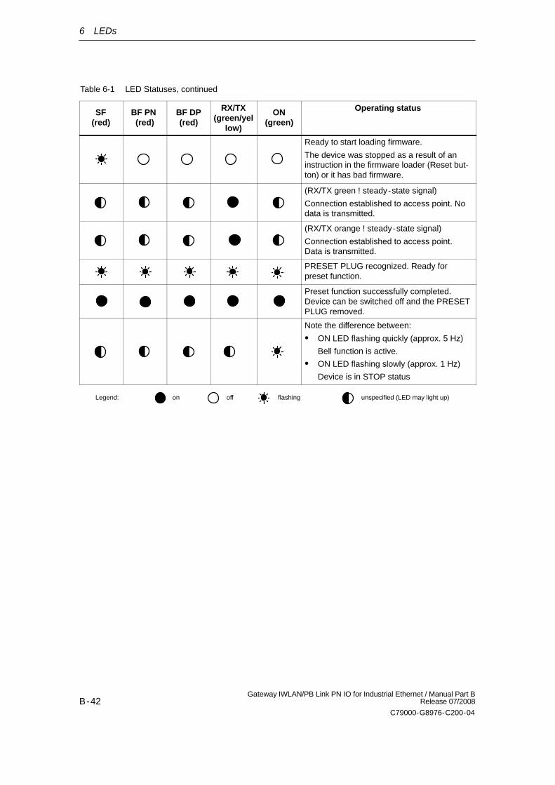
Table 6-1 LED Statuses, continued
SF(red)
Operating statusON(green)
RX/TX(green/yel
low)
BF DP(red)
BF PN (red)
Ready to start loading firmware.
The device was stopped as a result of aninstruction in the firmware loader (Reset but-ton) or it has bad firmware.
(RX/TX green ! steady-state signal)
Connection established to access point. Nodata is transmitted.
(RX/TX orange ! steady-state signal)
Connection established to access point.Data is transmitted.
PRESET PLUG recognized. Ready forpreset function.
Preset function successfully completed.Device can be switched off and the PRESETPLUG removed.
Note the difference between:
ON LED flashing quickly (approx. 5 Hz)
Bell function is active.
ON LED flashing slowly (approx. 1 Hz)
Device is in STOP status
Legend: on off flashing unspecified (LED may light up)
7 Performance Data
B-43Gateway IWLAN/PB Link PN IO for Industrial Ethernet / Manual Part BRelease 07/2008
C79000-G8976-C200-04
7 Performance Data
7.1 Characteristic Data for Wireless Links
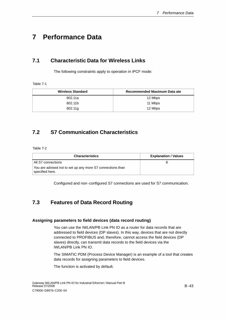
The following constraints apply to operation in iPCF mode:
Table 7-1
Wireless Standard Recommended Maximum Data ate
802.11a
802.11b
802.11g
12 Mbps
11 Mbps
12 Mbps
7.2 S7 Communication Characteristics
Table 7-2
Characteristics Explanation / Values
All S7 connections
You are advised not to set up any more S7 connections thanspecified here.
8
Configured and non-configured S7 connections are used for S7 communication.
7.3 Features of Data Record Routing
Assigning parameters to field devices (data record routing)
You can use the IWLAN/PB Link PN IO as a router for data records that areaddressed to field devices (DP slaves). In this way, devices that are not directlyconnected to PROFIBUS and, therefore, cannot access the field devices (DPslaves) directly, can transmit data records to the field devices via theIWLAN/PB Link PN IO.
The SIMATIC PDM (Process Device Manager) is an example of a tool that createsdata records for assigning parameters to field devices.
The function is activated by default.
7 Performance Data
B-44Gateway IWLAN/PB Link PN IO for Industrial Ethernet / Manual Part B
Release 07/2008
C79000-G8976-C200-04
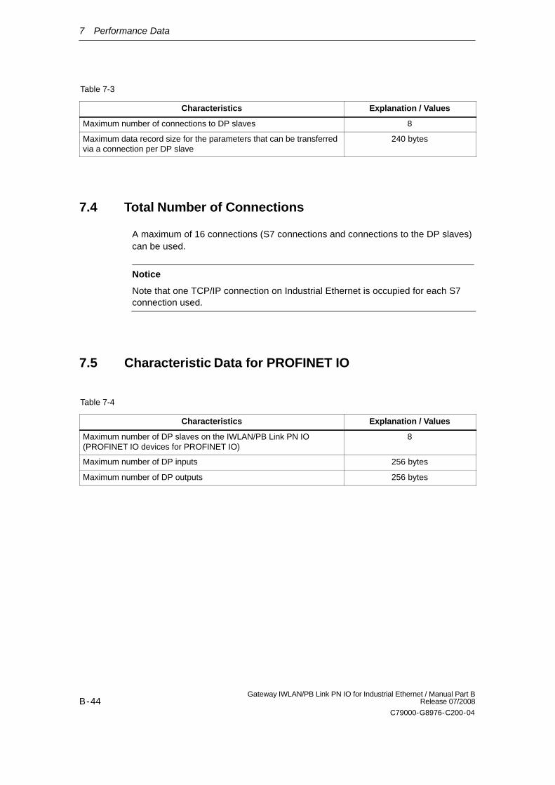
Table 7-3
Characteristics Explanation / Values
Maximum number of connections to DP slaves 8
Maximum data record size for the parameters that can be transferredvia a connection per DP slave
240 bytes
7.4 Total Number of Connections
A maximum of 16 connections (S7 connections and connections to the DP slaves)can be used.
Notice
Note that one TCP/IP connection on Industrial Ethernet is occupied for each S7connection used.
7.5 Characteristic Data for PROFINET IO
Table 7-4
Characteristics Explanation / Values
Maximum number of DP slaves on the IWLAN/PB Link PN IO(PROFINET IO devices for PROFINET IO)
8
Maximum number of DP inputs 256 bytes
Maximum number of DP outputs 256 bytes
8 Compatibility with Predecessor Products
B-45Gateway IWLAN/PB Link PN IO for Industrial Ethernet / Manual Part BRelease 07/2008
C79000-G8976-C200-04
8 Compatibility with Predecessor Products
8.1 Use as a replacement:
Changing to hardware version AS 03
As of hardware version AS 03, the IWLAN/PB Link PN IO uses a new IWLANwireless module with modified wireless properties compared with the IWLANwireless modules of hardware versions AS 01 and AS 02.
When converting to devices as of hardware version AS 03, the previousconfiguration on C-PLUG, Preset Plug and in the configuration file “config.cfg” canbe used in most cases.
When adopting a configuration, created with a hardware version lower than AS 03,remember the following:
The displayed parameter for the transmit power is adapted automaticallywithout resulting in changes to the transmit power. Example: At the setting “Half, 1/2 (-3dBm)”, a device with hardware version AS 03 has amaximum transmit power of 17 dBm. A device with a hardware version less than AS 03 also has a maximum transmitpower of 17 dBm if the “Transmit Power” parameter is set to “Full (-0dB)”. The parameters for other transmit power settings are also adaptedautomatically.
The antenna type is automatically set to the value “User Defined”. The value set for the antenna gain parameter is adopted. Example:The value “ANT795-6MR, 5m cable” is automatically converted to “User defined” with the appropriate antenna gain.
Note
The adaptation/transfer of the parameters is handled by the new deviceautomatically when it is restarted after adopting the old configuration.
There are, however, configurations in which the adaptation of the parameterscannot be handled by the firmware. In these cases, you will need to adapt theconfiguration manually.
8 Compatibility with Predecessor Products
B-46Gateway IWLAN/PB Link PN IO for Industrial Ethernet / Manual Part B
Release 07/2008
C79000-G8976-C200-04
When selecting channels in frequency bands with different limit values fortransmit power, it is possible that the list of selectable channels is restricted dueto the different wireless properties.This may mean that devices can no longer be reached via the wirelessinterface! When replacing devices with the previous versions with devices withhardware version AS 03, we therefore strongly recommend that these arechecked in a test environment to make sure that they adopt the channelselection unchanged. The channel selection is, for example dependent on the set transmit power andcan be influenced by modifications to the relevant parameters.Once a device with hardware version AS 03 has been assigned parameterswith a configuration file from an older device, all the parameters relating tonational approvals are checked.
Note
During a transitional period, it is possible that some national approvals are not yetavailable for the devices with hardware version AS 03 because the certificationprocess takes longer in some countries. You should therefore make sure that the devices are approved for your applicationby checking the following Internet page: http://www.siemens.com/simatic-net/ik-info
9 Further notes regarding operation
B-47Gateway IWLAN/PB Link PN IO for Industrial Ethernet / Manual Part BRelease 07/2008
C79000-G8976-C200-04
9 Further notes regarding operation
9.1 Changing interface parameters during download
If you change the interface parameters that are already set (e.g. the transmissionspeed), this can cause the download process to be aborted.
In this case, adjust the PG/PC interface and network configuration in line with thenew interface parameters and carry out the download again.
9.2 Time forwarding
If the time forwarding function in the IWLAN/PB Link PN IO is deactivated, thedevice uses the internal time, even if the Ethernet has a time master.
9.3 SNMP agent
SNMP (Simple Network Management Protocol)
The IWLAN/PB Link PN IO supports data querying via SNMP in version 1.
SNMP is a simple protocol language for managing networks. For datatransmission, SNMP is based on the connectionless protocol UDP.
Information about the properties of SNMP-capable devices is available in ”MIB”files (MIB = Managed Information Base). For more detailed information about usingMIB files, see the documentation provided with the SNMP clients used (example ofan SNMP client: SNMP OPC server of SIMATIC NET).
9 Further notes regarding operation
B-48Gateway IWLAN/PB Link PN IO for Industrial Ethernet / Manual Part B
Release 07/2008
C79000-G8976-C200-04
Supported MIBs
The IWLAN/PB Link PN IO supports all MIB objects in the standard MIB (inaccordance with MIB II (RFC 1213)).
Exceptions / restrictions:
Write access is enabled for the following MIB objects only:
sysContact, sysLocation, and sysName
In all other cases, only read access is enabled (for security reasons).
Access rights via community name
The IWLAN/PB Link PN IO uses the following community names to assign rights:
Read access: ”public”
Read/write access: ”private”
(Note use of lower case!)
Evaluating traps
To evaluate the IWLAN/PB Link PN IO traps, you need the appropriate private MIBfile for this device. The private MIB files contain the device andmanufacturer-specific MIB objects.
The private MIB file for the IWLAN/PB Link PN IO is in the SCALANCE W7xx typedevices. You can download them from there and import them to your trap receiver.
To do so, enter the following URL in your Web browser:
http://<IP-Adresse vom SCALANCE W7xx>/sniWlanPBLink.mib
10 How to Load New Firmware
B-49Gateway IWLAN/PB Link PN IO for Industrial Ethernet / Manual Part BRelease 07/2008
C79000-G8976-C200-04
10 How to Load New Firmware
Requirements
When downloading over PROFIBUS
- There must be a PROFIBUS CP module in the PG/PC.
When downloading over Industrial Ethernet
- To download firmware, you require an Industrial Ethernet CP module in thePG/PC (for example, CP 1613) or a normal Ethernet module with the“Softnet” software package.
- The S7-ONLINE interface must be set to the “ISO - Industrial Ethernet”protocol. It is not possible to download using TCP/IP (and therefore not toother networks).
How to Download New Firmware
You download new firmware to a SIMATIC NET CP using the firmware loadershipped with STEP 7 / NCM S7 for Industrial Ethernet and PROFIBUS.
Start the firmware loader and follow the instructions step-by-step.
What to do if a Download is Interrupted
Disturbances or collisions on the network can lead to packets being lost. In suchcases, this can lead to an interruption of the firmware download. The firmwareloader then signals a timeout or negative response from the module being loaded.
If you were unable to download the new firmware successfully, (download overIWLAN or PROFIBUS), you should run the download again directly overPROFIBUS.
If the device is not ready to accept the download, follow the steps below:
1. Turn off the power supply to the IWLAN/PB-Link
2. Press the Reset button and keep it depressed. Turn the power supply on againand wait until the SF-LED flashes.
3. Release the Reset button again; the device is now ready for the firmwareupdate over PROFIBUS using the firmware loader.
11 Technical data
B-50Gateway IWLAN/PB Link PN IO for Industrial Ethernet / Manual Part B
Release 07/2008
C79000-G8976-C200-04
11 Technical data
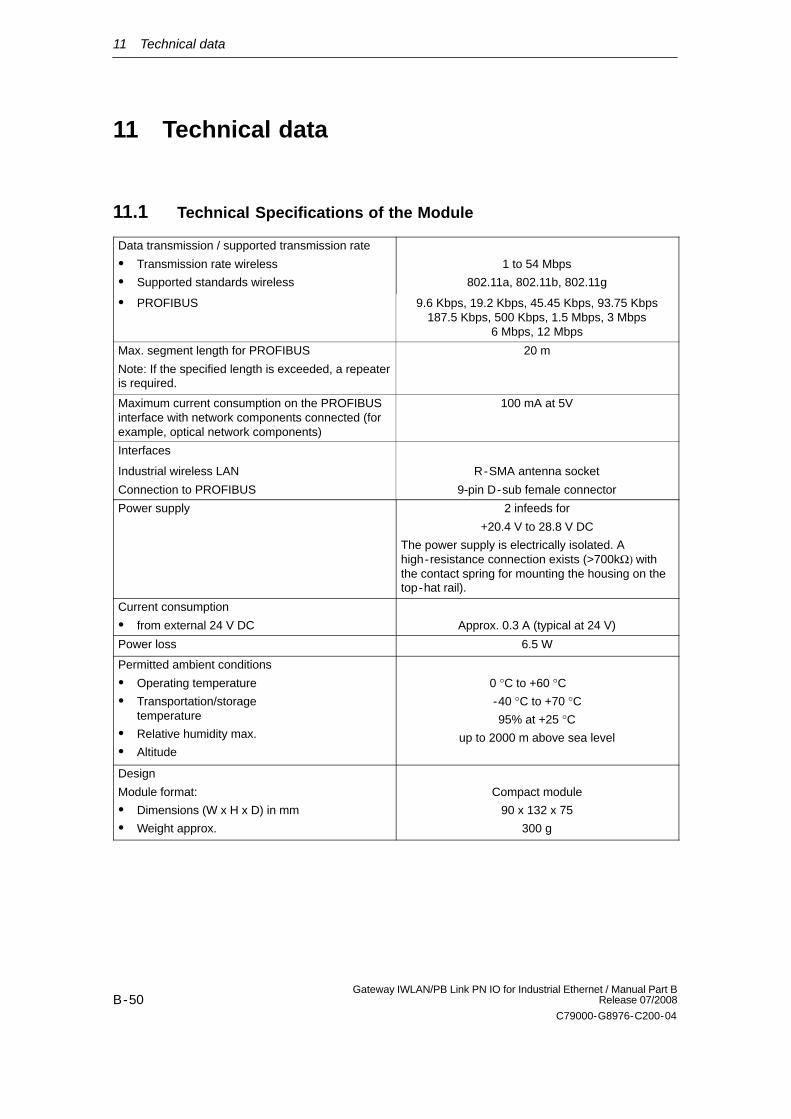
11.1 Technical Specifications of the Module
Data transmission / supported transmission rate
Transmission rate wireless
Supported standards wireless
1 to 54 Mbps
802.11a, 802.11b, 802.11g
PROFIBUS 9.6 Kbps, 19.2 Kbps, 45.45 Kbps, 93.75 Kbps187.5 Kbps, 500 Kbps, 1.5 Mbps, 3 Mbps
6 Mbps, 12 Mbps
Max. segment length for PROFIBUS
Note: If the specified length is exceeded, a repeateris required.
20 m
Maximum current consumption on the PROFIBUSinterface with network components connected (forexample, optical network components)
100 mA at 5V
Interfaces
Industrial wireless LAN
Connection to PROFIBUS
R-SMA antenna socket
9-pin D-sub female connector
Power supply 2 infeeds for
+20.4 V to 28.8 V DC
The power supply is electrically isolated. Ahigh-resistance connection exists (>700kΩ) withthe contact spring for mounting the housing on thetop-hat rail).
Current consumption
from external 24 V DC Approx. 0.3 A (typical at 24 V)
Power loss 6.5 W
Permitted ambient conditions
Operating temperature
Transportation/storage temperature
Relative humidity max.
Altitude
0 °C to +60 °C-40 °C to +70 °C95% at +25 °C
up to 2000 m above sea level
Design
Module format:
Dimensions (W x H x D) in mm
Weight approx.
Compact module
90 x 132 x 75
300 g
11 Technical data
B-51Gateway IWLAN/PB Link PN IO for Industrial Ethernet / Manual Part BRelease 07/2008
C79000-G8976-C200-04
For the IWLAN/PB Link PN IO, all the specifications for the following areas listed inthe ”General Technical Data” section in the /1/S7-300 Module Data: ReferenceManual:
Electromagnetic compatibility
Transportation and storage conditions
Mechanical and climatic ambient conditions
Insulation tests, class of protection and degree of protection
Exception: the module dimensions and installation procedure are different to thosefor SIMATIC S7-300.
11.1.1 Standards and Approvals
Notice
The Information in the section Standards and Approvals in the following docu-ments applies:
In the Operating Instructions (compact) accompanying the device describedhere;
In the General Part A of this manual.You can also download the current General Part A from Internet:
http://support.automation.siemens.com/WW/view/en/8777865
12 FCC Approval
B-52Gateway IWLAN/PB Link PN IO for Industrial Ethernet / Manual Part B
Release 07/2008
C79000-G8976-C200-04
12 FCC Approval
This device - Order-Nr.: 6GK1417-5AB01 (US-Variante) - complies with Part 15of the FCC Rules and with RSS-210 of Industry Canada.
Operation is subject to the following two conditions:
1. this device my not cause harmful interference, and
2. this device must accept any interference received, including interference thatmay cause undesired operation.
Notice
Changes or modifications made to this equipment not expressly approved bySIEMENS may void the FCC authorization to operate this equipment.
This equipment has been tested and found to comply with the limits for a Class Bdigital device, pursuant to Part 15 of the FCC Rules. These limits are designed toprovide reasonable protection against harmful interference in a residentialinstallation. This equipment generates, uses and can radiate radio frequencyenergy and, if not installed and used in accordance with the instructions, maycause harmful interference to radio communications. However, there is noguarantee that interference will not occur in a particular installation. If thisequipment does cause harmful interference to radio or television reception, whichcan be determined by turning the equipment off and on, the user is encouraged totry to correct the interference by one or more of the following measures:
Reorient or relocate the receiving antenna.
Increase the separation between the equipment and receiver.
Connect the equipment into an outlet on a circuit different from that to which thereceiver is connected.
Consult the dealer or an experienced radio/TV technician for help.
Notice
FCC Radiation Exposure Statement:
This equipment complies with FCC radiation exposure limits set forth for an uncon-trolled environment. This equipment should be installed and operated with mini-mum distance of 20cm between the radiator and your body.
This transmitter must not be co- located or operating in conjunction with any otherantenna or transmitter.