Embed Size (px)
DESCRIPTION
siemens
Citation preview

Preface, Contents
General Technical Specifications1
Power Supply Modules2
Digital Modules3
Analog Modules4
Other Signal Modules5
Interface Modules6
RS 485 Repeater7
SIMATIC TOP connect8
SIMATIC TOP connect TPA9
Appendices
Parameter Sets for SignalModules
A
Diagnostics Data of the SignalModules
B
Dimension DrawingsC
Spare Parts and Accessories forS7-300 Modules
D
Guidelines for Handling Electro-static Sensitive Devices (ESD)
E
List of AbbreviationsF
Glossary, Index
Edition 2
EWA 4NEB 710 6067-02 01
S7-300 and M7-300Programmable ControllersModule Specifications
Reference manual
This manual is part of the following documentation packageswith order nos: S7–300 Programmable Controller: 6ES7 398–8AA03–8BA0ET 200M Distributed I/O Device: 6ES7 153–1AA00–8BA0
SIMATIC
Index-2S7-300 and M7-300 Programmable Controllers Module Specifications
EWA 4NEB 710 6067-02 01
!Danger
indicates that death, severe personal injury or substantial property damage will result if proper precau-tions are not taken.
!Warning
indicates that death, severe personal injury or substantial property damage can result if proper precau-tions are not taken.
!Caution
indicates that minor personal injury or property damage can result if proper precautions are not taken.
Note
draws your attention to particularly important information on the product, handling the product, or to aparticular part of the documentation.
Qualified PersonnelOnly qualified personnel should be allowed to install and work on this equipment. Qualified persons aredefined as persons who are authorized to commission, to ground, and to tag circuits, equipment, and sys-tems in accordance with established safety practices and standards.
Correct UsageNote the following:
!Warning
This device and its components may only be used for the applications described in the catalog or thetechnical descriptions, and only in connection with devices or components from other manufacturerswhich have been approved or recommended by Siemens.
This product can only function correctly and safely if it is transported, stored, set up, and installed cor-rectly, and operated and maintained as recommended.
TrademarksSIMATIC, SIMATIC HMI and SIMATIC NET are registered trademarks of SIEMENS AG.
Some of other designations used in these documents are also registered trademarks; the owner’s rightsmay be violated if they are used by third parties for their own purposes.
Safety GuidelinesThis manual contains notices which you should observe to ensure your own personal safety, as well as toprotect the product and connected equipment. These notices are highlighted in the manual by a warningtriangle and are marked as follows according to the level of danger:
We have checked the contents of this manual for agreement with the hard-ware and software described. Since deviations cannot be precluded entirely,we cannot guarantee full agreement. However, the data in this manual arereviewed regularly and any necessary corrections included in subsequenteditions. Suggestions for improvement are welcomed.
Disclaimer of LiabilityCopyright Siemens AG 1998 All rights reserved
The reproduction, transmission or use of this document or its contents is notpermitted without express written authority. Offenders will be liable fordamages. All rights, including rights created by patent grant or registration ofa utility model or design, are reserved.
Siemens AGAutomation and Drives (A&D)Industrial Automation Systems (AS)Postfach 4848, D- 90327 Nürnberg
Siemens AG 1998Technical data subject to change.
Siemens Aktiengesellschaft
iiiS7-300 and M7-300 Programmable Controllers Module SpecificationsEWA 4NEB 710 6067-02 01
Preface
Purpose
The information contained in this manual will enable you to look up operatoractions, function descriptions and the technical specifications of the signalmodules, power supply modules and interface modules of the S7-300.
How to configure, assemble and wire these modules in an S7-300, M7-300 orET 200M system is described in the installation manuals for each system.
Audience
This manual describes the modules of the S7-300 which are used in the S7-300,M7-300 and ET 200M systems. It includes data sheets for the signal modules,power supply modules and interface modules of the S7-300.
Modifications Since the Last Version
The following modifications have been made since the last version of the “ModuleData” reference manual:
new is Chapter 1.7 “SIMATIC Outdoor Modules” for use under extendedenvironmental conditions
new is Chapter 9 “SIMATIC TOP connect TPA”
the following signal modules have been added:
– SM 321; DI 32 x 120 VAC
– SM 322; DO 32 x 120 VAC/1.0 A
– SM 322; DO 8 x Rel. 230 VAC/5 A
– SM 331; AI 8 x 16 Bit
– SM 332; AO 4 x 16 Bit
– SM 334; AI 4/AO 2 x 12 Bit
– SM 338 POS input module
Note: You can recognize the previous version of this “Module Data” referencemanual by the number EWA 4NEB 710 6067-0x in the footer.
The current number is: EWA 4NEB 710 6067-0x 01.
Preface
ivS7-300 and M7-300 Programmable Controllers Module Specifications
EWA 4NEB 710 6067-02 01
Standards and Approvals
The S7-300 fulfills the requirements and criteria of the IEC 1131, Part 2. TheS7-300 fulfills the requirements for CE marking. The approbations for CSA, UL andFM are available for the S7-300.
Details on the approbations and standards are given in Section 1.1.
Preface
vS7-300 and M7-300 Programmable Controllers Module SpecificationsEWA 4NEB 710 6067-02 01
Scope of the Documentation Package
This manual forms part of the documentation for the S7-300, M7-300 andET 200M.
System Documentation Package
S7-300 S7-300 Programmable Controller, Installation and Hardware
S7-300, M7-300 Programmable Controllers, ModuleSpecifications
S7-300 Instruction List
M7-300 M7-300 Programmable Controller, Installation and Hardware
S7-300, M7-300 Programmable Controllers, ModuleSpecifications
ET 200M ET 200M Distributed I/O Device
S7-300, M7-300 Programmable Controllers, ModuleSpecifications
CD-ROM
Note: You can also order the complete SIMATIC S7 documentation on CD-ROM.
How to Use this Manual
To help you find special information quickly, the manual contains the followingaccess aids:
At the start of the manual you will find a complete table of contents and a list ofthe diagrams and tables that appear in the manual.
An overview of the contents of each section is provided in the left column oneach page of each chapter.
You will find a glossary in the appendix at the end of the manual. The glossarycontains definitions of the main technical terms used in the manual.
At the end of the manual you will find a comprehensive index which gives youfast access to the information you need.
Preface
viS7-300 and M7-300 Programmable Controllers Module Specifications
EWA 4NEB 710 6067-02 01
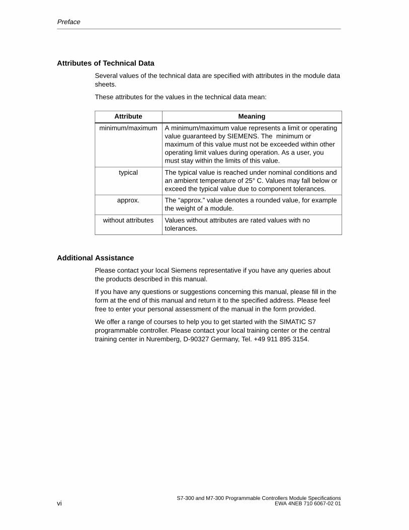
Attributes of Technical Data
Several values of the technical data are specified with attributes in the module datasheets.
These attributes for the values in the technical data mean:
Attribute Meaning
minimum/maximum A minimum/maximum value represents a limit or operatingvalue guaranteed by SIEMENS. The minimum ormaximum of this value must not be exceeded within otheroperating limit values during operation. As a user, youmust stay within the limits of this value.
typical The typical value is reached under nominal conditions andan ambient temperature of 25° C. Values may fall below orexceed the typical value due to component tolerances.
approx. The “approx.” value denotes a rounded value, for examplethe weight of a module.
without attributes Values without attributes are rated values with notolerances.
Additional Assistance
Please contact your local Siemens representative if you have any queries aboutthe products described in this manual.
If you have any questions or suggestions concerning this manual, please fill in theform at the end of this manual and return it to the specified address. Please feelfree to enter your personal assessment of the manual in the form provided.
We offer a range of courses to help you to get started with the SIMATIC S7programmable controller. Please contact your local training center or the centraltraining center in Nuremberg, D-90327 Germany, Tel. +49 911 895 3154.
viiS7-300 and M7-300 Programmable Controllers Module SpecificationsEWA 4NEB 710 6067-02 01
Contents
Preface
1 General Technical Specifications
1.1 Standards and Approvals 1-2. . . . . . . . . . . . . . . . . . . . . . . . . . . . . . . . . . . . . . . . .
1.2 Electromagnetic Compatibility of S7-300 Modules 1-4. . . . . . . . . . . . . . . . . . . .
1.3 Transport and Storage Conditions for S7-300 Modules and Backup Batteries 1-6. . . . . . . . . . . . . . . . . . . . . . . . . . . . . . . . . . . . . . . . . . . . . . . . .
1.4 Mechanical and Climatic Environmental Conditions for Operating S7-300s 1-7. . . . . . . . . . . . . . . . . . . . . . . . . . . . . . . . . . . . . . . . . . . .
1.5 Information on Insulation Tests, Protection Class and Degree of Protection 1-10. . . . . . . . . . . . . . . . . . . . . . . . . . . . . . . . . . . . . . . . . . . . . . . . . . . . . . .
1.6 Rated Voltages of the S7-300 1-11. . . . . . . . . . . . . . . . . . . . . . . . . . . . . . . . . . . . . .
1.7 SIMATIC Outdoor Modules 1-12. . . . . . . . . . . . . . . . . . . . . . . . . . . . . . . . . . . . . . . .
2 Power Supply Modules
2.1 The PS 307 Power Supply Module (2 A) 2-2. . . . . . . . . . . . . . . . . . . . . . . . . . . .
2.2 The PS 307 Power Supply Module (5 A) 2-6. . . . . . . . . . . . . . . . . . . . . . . . . . . .
2.3 The PS 307 Power Supply Module (10 A) 2-11. . . . . . . . . . . . . . . . . . . . . . . . . . .
3 Digital Modules
3.1 Digital Input Modules 3-2. . . . . . . . . . . . . . . . . . . . . . . . . . . . . . . . . . . . . . . . . . . . . 3.1.1 Digital Input Module SM 321; DI 32 24 VDC 3-2. . . . . . . . . . . . . . . . . . . . . . . 3.1.2 Digital Input Module SM 321; DI 16 24 VDC 3-6. . . . . . . . . . . . . . . . . . . . . . . 3.1.3 Digital Input Module SM 321; DI 16 24 VDC; with Process and
Diagnostics Interrupts 3-9. . . . . . . . . . . . . . . . . . . . . . . . . . . . . . . . . . . . . . . . . . . . 3.1.4 Digital Input Module SM 321; DI 16 24 VDC (Source Input) 3-19. . . . . . . . . 3.1.5 Digital Input Module SM 321; DI 16 120 VAC 3-23. . . . . . . . . . . . . . . . . . . . . . 3.1.6 Digital Input Module SM 321; DI 8 120/230 VAC 3-25. . . . . . . . . . . . . . . . . . . 3.1.7 Digital Input Module SM 321; DI 32 120 VAC 3-28. . . . . . . . . . . . . . . . . . . . . .
3.2 Digital Output Modules 3-31. . . . . . . . . . . . . . . . . . . . . . . . . . . . . . . . . . . . . . . . . . . . 3.2.1 Digital Output Module SM 322; DO 32 24 VDC/0.5 A 3-31. . . . . . . . . . . . . . . 3.2.2 Digital Output Module SM 322; DO 16 24 VDC/0.5 A 3-35. . . . . . . . . . . . . . . 3.2.3 Digital Output Module SM 322; DO 8 24 VDC/0.5 A;
with Diagnostics Interrupt 3-38. . . . . . . . . . . . . . . . . . . . . . . . . . . . . . . . . . . . . . . . . 3.2.4 Digital Output Module SM 322; DO 8 24 VDC/2 A 3-47. . . . . . . . . . . . . . . . . . 3.2.5 Digital Output Module SM 322; DO 16 120 VAC/1 A 3-50. . . . . . . . . . . . . . . . 3.2.6 Digital Output Module SM 322; DO 8 120/230 VAC/2 A 3-53. . . . . . . . . . . . . 3.2.7 Digital Output Module SM 322; D0 32 20 VAC/1.0 A 3-56. . . . . . . . . . . . . . .
Contents
viiiS7-300 and M7-300 Programmable Controllers Module Specifications
EWA 4NEB 710 6067-02 01
3.3 Relay Output Modules 3-59. . . . . . . . . . . . . . . . . . . . . . . . . . . . . . . . . . . . . . . . . . . . 3.3.1 Relay Output Module SM 322; DO 16 120 VAC REL. 3-59. . . . . . . . . . . . . . . 3.3.2 Relay Output Module SM 322; DO 8 230 VAC REL. 3-62. . . . . . . . . . . . . . . . 3.3.3 Digital output Module SM 322; DO 8 Rel. 230 VAC/5 A 3-66. . . . . . . . . . . . .
3.4 Digital Input/Output Modules 3-70. . . . . . . . . . . . . . . . . . . . . . . . . . . . . . . . . . . . . . . 3.4.1 Digital Input/Output Module SM 323; DI 16/DO 16 24 VDC/0.5 A 3-70. . . . . 3.4.2 Digital Input/Output Module SM 323; DI 8/DO 8 24 VDC/0.5 A 3-74. . . . . . .
4 Analog Modules
4.1 Analog Value Representation 4-2. . . . . . . . . . . . . . . . . . . . . . . . . . . . . . . . . . . . . . 4.1.1 Representation of Analog Input and Output Values 4-2. . . . . . . . . . . . . . . . . . . 4.1.2 Analog Value Representation of the Measuring Ranges
of the Analog Inputs 4-4. . . . . . . . . . . . . . . . . . . . . . . . . . . . . . . . . . . . . . . . . . . . . . 4.1.3 Analog Value Representation of the Output Ranges
of the Analog Outputs 4-16. . . . . . . . . . . . . . . . . . . . . . . . . . . . . . . . . . . . . . . . . . . .
4.2 Connecting Sensors/Transducers and Loads/Actuators to Analog Modules 4-18. . . . . . . . . . . . . . . . . . . . . . . . . . . . . . . . . . . . . . . . . . . . . . .
4.2.1 Connecting Sensors/Transducers to Analog Inputs 4-19. . . . . . . . . . . . . . . . . . . 4.2.2 Using Thermocouples 4-25. . . . . . . . . . . . . . . . . . . . . . . . . . . . . . . . . . . . . . . . . . . . 4.2.3 Connecting Voltage and Current Sensors and
Resistance-TypeThermometers 4-31. . . . . . . . . . . . . . . . . . . . . . . . . . . . . . . . . . . . 4.2.4 Connecting Loads/Actuators to Analog Outputs 4-34. . . . . . . . . . . . . . . . . . . . . .
4.3 Fundamental Principles for the Use of Analog Modules 4-38. . . . . . . . . . . . . . . 4.3.1 Conversion and Cycle Time of the Analog Input Channels 4-39. . . . . . . . . . . . . 4.3.2 Conversion, Cycle, Setting and Response Times of the Analog Output
Channels 4-41. . . . . . . . . . . . . . . . . . . . . . . . . . . . . . . . . . . . . . . . . . . . . . . . . . . . . . . 4.3.3 Setting the Measuring Method and the Measuring Ranges
of the Analog Input Channels 4-43. . . . . . . . . . . . . . . . . . . . . . . . . . . . . . . . . . . . . . 4.3.4 Parameters of the Analog Modules 4-47. . . . . . . . . . . . . . . . . . . . . . . . . . . . . . . . . 4.3.5 Diagnostics of the Analog Modules 4-51. . . . . . . . . . . . . . . . . . . . . . . . . . . . . . . . . 4.3.6 Analog Module Interrupts 4-55. . . . . . . . . . . . . . . . . . . . . . . . . . . . . . . . . . . . . . . . . 4.3.7 Behavior of the Analog Modules 4-56. . . . . . . . . . . . . . . . . . . . . . . . . . . . . . . . . . .
4.4 Analog Input Module SM 331; AI 812 Bit 4-59. . . . . . . . . . . . . . . . . . . . . . . . . . 4.4.1 Characteristic Features and Technical Specifications of the Analog Input
Module SM 331; AI 8 12 Bit 4-60. . . . . . . . . . . . . . . . . . . . . . . . . . . . . . . . . . . . . 4.4.2 Starting Up the Analog Input Module SM 331; AI 8 12 Bit 4-64. . . . . . . . . . . 4.4.3 Measuring Methods and Measuring Ranges of the Analog Input Module
SM 331; AI 8 12 Bit 4-67. . . . . . . . . . . . . . . . . . . . . . . . . . . . . . . . . . . . . . . . . . . .
4.5 Analog Input Module SM 331; AI 8 16 Bit 4-70. . . . . . . . . . . . . . . . . . . . . . . . . 4.5.1 Starting Up the Analog Input Module SM 331; AI 8 16 Bit 4-74. . . . . . . . . . . 4.5.2 Measuring Methods and Measuring Ranges of the Analog Input Module
SM 331; AI 8 16 Bit 4-76. . . . . . . . . . . . . . . . . . . . . . . . . . . . . . . . . . . . . . . . . . . .
4.6 Analog Input Module SM 331; AI 212 Bit 4-79. . . . . . . . . . . . . . . . . . . . . . . . . . 4.6.1 Characteristic Features and Technical Specifications of the Analog Input
Module SM 331; AI 212 Bit 4-80. . . . . . . . . . . . . . . . . . . . . . . . . . . . . . . . . . . . . . 4.6.2 Starting Up the Analog Input Module SM 331; AI 212 Bit 4-84. . . . . . . . . . . . 4.6.3 Measuring Methods and Measuring Ranges of the Analog Input Module
SM 331; AI 212 Bit 4-87. . . . . . . . . . . . . . . . . . . . . . . . . . . . . . . . . . . . . . . . . . . . .
4.7 Analog Output Module SM 332; AO 4 12 Bit 4-90. . . . . . . . . . . . . . . . . . . . . .
Contents
ixS7-300 and M7-300 Programmable Controllers Module SpecificationsEWA 4NEB 710 6067-02 01
4.7.1 Characteristic Features and Technical Specifications of the Analog Output Module SM 332; AO 4 12 Bit 4-90. . . . . . . . . . . . . . . . . . . . . .
4.7.2 Starting Up the Analog Output Module SM 332; AO 4 12 Bit 4-94. . . . . . . . . 4.7.3 Output Ranges of the Analog Output Module SM 332; AO 4 12 Bit 4-95. . .
4.8 Analog Output Module SM 332; AO 212 Bit 4-96. . . . . . . . . . . . . . . . . . . . . . . . 4.8.1 Characteristic Features and Technical Specifications of the
Analog Output Module SM 332; AO 212 Bit 4-97. . . . . . . . . . . . . . . . . . . . . . . . 4.8.2 Starting Up the Analog Output Module SM 332; AO 212 Bit 4-101. . . . . . . . . . 4.8.3 Output Ranges of the Analog Output Module SM 332; AO 212 Bit 4-102. . . .
4.9 Analog Output Module SM 332; AO 4 16 Bit 4-103. . . . . . . . . . . . . . . . . . . . . . 4.9.1 Starting Up the Analog Output Module SM 332; AO 4 16 Bit 4-107. . . . . . . . . 4.9.2 Output Ranges of the Analog Output Module SM 332;
AO 4 16 Bit 4-108. . . . . . . . . . . . . . . . . . . . . . . . . . . . . . . . . . . . . . . . . . . . . . . . . . . .
4.10 Analog Input/Output Module SM 334; AI 4/AO 2 8/8 Bit 4-109. . . . . . . . . . . . . 4.10.1 Characteristic Features and Technical Specifications of the
Analog Input/Output Module SM 334; AI 4/AO 2 8/8 Bit 4-109. . . . . . . . . . . . . 4.10.2 Starting Up the Analog Input/Output Module SM 334;
AI 4/AO 2 8/8 Bit 4-113. . . . . . . . . . . . . . . . . . . . . . . . . . . . . . . . . . . . . . . . . . . . . . 4.10.3 Measurement Method and Type of Output of the Analog Input/Output
Module SM 334; AI 4/AO 2 8/8 Bit 4-113. . . . . . . . . . . . . . . . . . . . . . . . . . . . . . .
4.11 Analog Input/Output Module SM334; AI 4/AO 212 Bit 4-115. . . . . . . . . . . . . . . 4.11.1 Starting Up the SM 334 4-120. . . . . . . . . . . . . . . . . . . . . . . . . . . . . . . . . . . . . . . . . . . 4.11.2 Analog Value Representation 4-121. . . . . . . . . . . . . . . . . . . . . . . . . . . . . . . . . . . . . . 4.11.3 Parameters 4-123. . . . . . . . . . . . . . . . . . . . . . . . . . . . . . . . . . . . . . . . . . . . . . . . . . . . .
5 Other Signal Modules
5.1 Simulator Module SM 374; IN/OUT 16 5-2. . . . . . . . . . . . . . . . . . . . . . . . . . . . . .
5.2 Dummy Module DM 370 5-4. . . . . . . . . . . . . . . . . . . . . . . . . . . . . . . . . . . . . . . . . .
5.3 SM 338 POS Input Module 5-7. . . . . . . . . . . . . . . . . . . . . . . . . . . . . . . . . . . . . . . . 5.3.1 Connection Diagram 5-8. . . . . . . . . . . . . . . . . . . . . . . . . . . . . . . . . . . . . . . . . . . . . . 5.3.2 How the SM 338 Works 5-9. . . . . . . . . . . . . . . . . . . . . . . . . . . . . . . . . . . . . . . . . . . 5.3.3 Freeze Function 5-11. . . . . . . . . . . . . . . . . . . . . . . . . . . . . . . . . . . . . . . . . . . . . . . . . 5.3.4 Parameterization 5-13. . . . . . . . . . . . . . . . . . . . . . . . . . . . . . . . . . . . . . . . . . . . . . . . . 5.3.5 Data Handling 5-14. . . . . . . . . . . . . . . . . . . . . . . . . . . . . . . . . . . . . . . . . . . . . . . . . . . 5.3.6 Diagnostic Messages of the SM 338 5-15. . . . . . . . . . . . . . . . . . . . . . . . . . . . . . . . 5.3.7 Technical Specifications 5-17. . . . . . . . . . . . . . . . . . . . . . . . . . . . . . . . . . . . . . . . . . . 5.3.8 Configuration and Parameter Assignment Frame 5-18. . . . . . . . . . . . . . . . . . . . .
6 Interface Modules 6-1. . . . . . . . . . . . . . . . . . . . . . . . . . . . . . . . . . . . . . . . . . . . . . . . . . . . . . .
6.1 Interface Module IM 360 6-2. . . . . . . . . . . . . . . . . . . . . . . . . . . . . . . . . . . . . . . . . .
6.2 Interface Module IM 361 6-4. . . . . . . . . . . . . . . . . . . . . . . . . . . . . . . . . . . . . . . . . .
6.3 Interface Module IM 365 6-6. . . . . . . . . . . . . . . . . . . . . . . . . . . . . . . . . . . . . . . . . .
7 RS 485 Repeater 7-1. . . . . . . . . . . . . . . . . . . . . . . . . . . . . . . . . . . . . . . . . . . . . . . . . . . . . . . . .
7.1 Application and Properties 7-2. . . . . . . . . . . . . . . . . . . . . . . . . . . . . . . . . . . . . . . .
7.2 Technical Specifications 7-5. . . . . . . . . . . . . . . . . . . . . . . . . . . . . . . . . . . . . . . . . . .
Contents
xS7-300 and M7-300 Programmable Controllers Module Specifications
EWA 4NEB 710 6067-02 01
8 SIMATIC TOP connect
8.1 Application Areas and Components of SIMATIC TOP Connect 8-2. . . . . . . . .
8.2 Terminal Assignments for Wiring the Terminal Block 8-7. . . . . . . . . . . . . . . . . .
8.3 Wiring Rules for the Terminal Block and the Front Connector 8-9. . . . . . . . . .
8.4 Screw-Type Connections or Spring-Loaded Connections 8-10. . . . . . . . . . . . . .
8.5 Preparing the Connecting Cables 8-11. . . . . . . . . . . . . . . . . . . . . . . . . . . . . . . . . .
8.6 Wiring the Front Connector and the Terminal Block 8-13. . . . . . . . . . . . . . . . . . .
8.7 Wiring Digital Modules with SIMATIC TOP Connect 8-15. . . . . . . . . . . . . . . . . . .
9 SIMATIC TOP connect TP A
A Parameter Sets for Signal Modules
A.1 How to Assign the Parameters for Signal Modules in the User Program A-2.
A.2 Parameters of the Digital Input Modules A-3. . . . . . . . . . . . . . . . . . . . . . . . . . . . .
A.3 Parameters of the Digital Output Modules A-5. . . . . . . . . . . . . . . . . . . . . . . . . . .
A.4 Parameters of the Analog Input Modules A-7. . . . . . . . . . . . . . . . . . . . . . . . . . . .
A.5 Parameters of the Analog Output Modules A-11. . . . . . . . . . . . . . . . . . . . . . . . . .
B Diagnostics Data of the Signal Modules
C Dimension Drawings
C.1 Dimension Drawings of the Rails C-2. . . . . . . . . . . . . . . . . . . . . . . . . . . . . . . . . . .
C.2 Dimension Drawings of the Power Supply Modules C-9. . . . . . . . . . . . . . . . . . .
C.3 Dimension Drawings of the Interface Modules C-14. . . . . . . . . . . . . . . . . . . . . . .
C.4 Dimension Drawings of the Signal Modules C-17. . . . . . . . . . . . . . . . . . . . . . . . . .
C.5 Dimension Drawings for Accessories C-18. . . . . . . . . . . . . . . . . . . . . . . . . . . . . . .
D Spare Parts and Accessories for S7-300 Modules
E Guidelines for Handling Electrostatic Sensitive Devices (ESD)
E.1 What is ESD? E-2. . . . . . . . . . . . . . . . . . . . . . . . . . . . . . . . . . . . . . . . . . . . . . . . . . .
E.2 Electrostatic Charging of Persons E-3. . . . . . . . . . . . . . . . . . . . . . . . . . . . . . . . . .
E.3 General Protective Measures Against Electrostatic Discharge Damage E-4.
F List of Abbreviations
Glossary
Index
Contents
xiS7-300 and M7-300 Programmable Controllers Module SpecificationsEWA 4NEB 710 6067-02 01
Figures
2-1 Wiring Schematic of the PS 307 Power Supply Module (2 A) 2-3. . . . . . . . . . . 2-2 Basic Circuit Diagram of the PS 307 Power Supply Module (2 A) 2-4. . . . . . . 2-3 Wiring Schematic of the PS 307 Power Supply Module (5 A) 2-7. . . . . . . . . . . 2-4 Basic Circuit Diagram of the PS 307 Power Supply Module (5 A) 2-8. . . . . . . 2-5 Wiring Schematic of the PS 307 Power Supply Module (10 A) 2-12. . . . . . . . . 2-6 Basic Circuit Diagram of the PS 307 Power Supply Module (10 A) 2-13. . . . . . 3-1 Module View and Block Diagram of the Digital Input Module SM 321;
DI 3224VDC 3-3. . . . . . . . . . . . . . . . . . . . . . . . . . . . . . . . . . . . . . . . . . . . . . . . . . 3-2 Module View and Block Diagram of Digital Input Module SM 321;
DI 16 24 VDC 3-7. . . . . . . . . . . . . . . . . . . . . . . . . . . . . . . . . . . . . . . . . . . . . . . . . 3-3 Module View and Block Diagram of the SM 321; DI 16 24 VDC
with Process and Diagnostics Interrupts 3-10. . . . . . . . . . . . . . . . . . . . . . . . . . . . . 3-4 Terminal Connection Diagram for the Redundant Supply of Sensors 3-10. . . . 3-5 Module View and Block Diagram of Digital Input Module SM 321;
DI 1624 VDC (Source Input) 3-20. . . . . . . . . . . . . . . . . . . . . . . . . . . . . . . . . . . . . 3-6 Module View and Block Diagram of Digital Input Module SM 321;
DI 16120 VAC 3-23. . . . . . . . . . . . . . . . . . . . . . . . . . . . . . . . . . . . . . . . . . . . . . . . . 3-7 Module View and Block Diagram of Digital Input Module SM 321;
DI 8120/230 VAC 3-26. . . . . . . . . . . . . . . . . . . . . . . . . . . . . . . . . . . . . . . . . . . . . . 3-8 Terminal Connection Diagram and Block Diagram of Digital Input Module
SM 321; DI 32 120 VAC 3-29. . . . . . . . . . . . . . . . . . . . . . . . . . . . . . . . . . . . . . . . . 3-9 Module View and Block Diagram of Digital Output Module SM 322;
DO 32 24 VDC/0.5 A 3-32. . . . . . . . . . . . . . . . . . . . . . . . . . . . . . . . . . . . . . . . . . . 3-10 Module View and Block Diagram of Digital Output Module SM 322;
DO 16 24 VDC/0.5 A 3-36. . . . . . . . . . . . . . . . . . . . . . . . . . . . . . . . . . . . . . . . . . . 3-11 Terminal Connection Diagram and Block Diagram of Digital Output
Module SM 322; DO 8 24 VDC/0.5 A; with Diagnostics Interrupt 3-39. . . . . . 3-12 Block Diagram of Digital Input Module SM 322; DO 824 VDC/0.5 A;
with Diagnostics Interrupt 3-40. . . . . . . . . . . . . . . . . . . . . . . . . . . . . . . . . . . . . . . . . 3-13 Module View and Block Diagram of Digital Output Module SM 322;
DO 8 24 VDC/2 A 3-48. . . . . . . . . . . . . . . . . . . . . . . . . . . . . . . . . . . . . . . . . . . . . 3-14 Module View and Block Diagram of Digital Output Module SM 322;
DO 16 120 VAC/1 A 3-51. . . . . . . . . . . . . . . . . . . . . . . . . . . . . . . . . . . . . . . . . . . 3-15 Module View and Block Diagram of the Digital Output Module SM 322;
DO 8 AC 120/230 V/2 A 3-54. . . . . . . . . . . . . . . . . . . . . . . . . . . . . . . . . . . . . . . . 3-16 Terminal Connection Diagram and Block Diagram of Digital Output
Module SM 322; D0 32 120 VAC/1.0 A 3-57. . . . . . . . . . . . . . . . . . . . . . . . . . . . 3-17 Module View and Block Diagram of Relay Output Module SM 322;
DO 16 120 VAC REL. 3-60. . . . . . . . . . . . . . . . . . . . . . . . . . . . . . . . . . . . . . . . . . 3-18 Module View and Block Diagram of Relay Output Module SM 322;
DO 8 230 VAC REL. 3-63. . . . . . . . . . . . . . . . . . . . . . . . . . . . . . . . . . . . . . . . . . . 3-19 Module View and Block Diagram of Digital Output Module SM 322;
DO 8Rel. 230 VAC/5 A 3-67. . . . . . . . . . . . . . . . . . . . . . . . . . . . . . . . . . . . . . . . . . 3-20 Module View and Block Diagram of the SM 323;
DI 16/DO 16 24 VDC/0.5 A 3-71. . . . . . . . . . . . . . . . . . . . . . . . . . . . . . . . . . . . . 3-21 Module View and Block Diagram of Digital Input/Output Module SM 323;
DI 8/DO 8 24 VDC/0.5 A 3-75. . . . . . . . . . . . . . . . . . . . . . . . . . . . . . . . . . . . . . . .
Contents
xiiS7-300 and M7-300 Programmable Controllers Module Specifications
EWA 4NEB 710 6067-02 01
4-1 Connecting Isolated Sensors to an Isolated Analog Input Module 4-22. . . . . . . 4-2 Connecting Isolated Sensors to a Non-Isolated Analog Input Module 4-23. . . 4-3 Connecting Non-Isolated Sensors to an Isolated Analog Input Module 4-24. . 4-4 Connecting Non-Isolated Sensors to a Non-Isolated Analog
Input Module 4-25. . . . . . . . . . . . . . . . . . . . . . . . . . . . . . . . . . . . . . . . . . . . . . . . . . . . 4-5 Design of Thermocouples 4-26. . . . . . . . . . . . . . . . . . . . . . . . . . . . . . . . . . . . . . . . . 4-6 Connection of Thermocouples with External Compensating Box to an
Isolated Analog Input Module 4-29. . . . . . . . . . . . . . . . . . . . . . . . . . . . . . . . . . . . . . 4-7 Connection of Thermocouples with Internal Compensation to an Isolated
Analog Input Module 4-30. . . . . . . . . . . . . . . . . . . . . . . . . . . . . . . . . . . . . . . . . . . . . 4-8 Connecting Voltage Sensors to an Isolated Analog Input Module 4-31. . . . . . . 4-9 Connecting 2-Wire Transducers to an Isolated Analog Input Module 4-32. . . . 4-10 Connecting 4-Wire Transducers to an Isolated Analog Input Module 4-32. . . . 4-11 Connecting Resistance-Type Thermometers to an Isolated
Analog Input Module 4-33. . . . . . . . . . . . . . . . . . . . . . . . . . . . . . . . . . . . . . . . . . . . . 4-12 Connecting Loads to a Current Output of an Isolated Analog
Output Module 4-35. . . . . . . . . . . . . . . . . . . . . . . . . . . . . . . . . . . . . . . . . . . . . . . . . . . 4-13 Connecting Loads to a Non-Isolated Analog Output Module 4-36. . . . . . . . . . . 4-14 Connecting Loads to a Voltage Output of an Isolated Analog Output
Module over a 4-Wire Circuit 4-37. . . . . . . . . . . . . . . . . . . . . . . . . . . . . . . . . . . . . . 4-15 Connecting Loads to a Voltage Output of a Non-Isolated Analog Output
Module over a 2-Wire Circuit 4-38. . . . . . . . . . . . . . . . . . . . . . . . . . . . . . . . . . . . . . 4-16 Cycle Time of the Analog Input Module 4-40. . . . . . . . . . . . . . . . . . . . . . . . . . . . . 4-17 Cycle Time of the Analog Output Module 4-41. . . . . . . . . . . . . . . . . . . . . . . . . . . . 4-18 Response Time of the Analog Output Channels 4-42. . . . . . . . . . . . . . . . . . . . . . 4-19 Markings for the Measuring Range Module 4-44. . . . . . . . . . . . . . . . . . . . . . . . . . 4-20 Easing a Measuring Range Module out of Analog Input Module SM 331;
AI 8 12 Bit 4-45. . . . . . . . . . . . . . . . . . . . . . . . . . . . . . . . . . . . . . . . . . . . . . . . . . . . 4-21 Inserting a Measuring Range Module into Analog Input Module SM 331;
AI 8 12 Bit 4-46. . . . . . . . . . . . . . . . . . . . . . . . . . . . . . . . . . . . . . . . . . . . . . . . . . . . 4-22 Module View and Block Diagram of the Analog Input Module SM 331;
AI 8 12 Bit 4-61. . . . . . . . . . . . . . . . . . . . . . . . . . . . . . . . . . . . . . . . . . . . . . . . . . . . 4-23 Terminal Connection Diagram and Block Diagram of Analog Input
Module SM 331; AI 8 x 16 Bit 4-71. . . . . . . . . . . . . . . . . . . . . . . . . . . . . . . . . . . . . . 4-24 Module View and Block Diagram of the Analog Input Module SM 331;
AI 212Bit 4-81. . . . . . . . . . . . . . . . . . . . . . . . . . . . . . . . . . . . . . . . . . . . . . . . . . . . . . 4-25 Module View and Block Diagram of the Analog Output Module SM 332;
AO 4 12 Bit 4-91. . . . . . . . . . . . . . . . . . . . . . . . . . . . . . . . . . . . . . . . . . . . . . . . . . . 4-26 Module View and Block Diagram of the Analog Output Module SM 332;
AO 212 Bit 4-98. . . . . . . . . . . . . . . . . . . . . . . . . . . . . . . . . . . . . . . . . . . . . . . . . . . . 4-27 Block Diagram of Analog Output Module SM 332; AO 4 x 16 Bit 4-104. . . . . . . . 4-28 Module View and Block Diagram of the Analog Input/Output Module
SM 334; AI 4/AO 2 8/8 Bit 4-110. . . . . . . . . . . . . . . . . . . . . . . . . . . . . . . . . . . . . . 4-29 Module View and Block Diagram of the SM 334 4-116. . . . . . . . . . . . . . . . . . . . . . 4-30 Record 1 of the SM 334 parameters 4-124. . . . . . . . . . . . . . . . . . . . . . . . . . . . . . . . 5-1 Front View of Simulator Module SM 374; IN/OUT 16 5-3. . . . . . . . . . . . . . . . . . 5-2 Front and Rear View of the Dummy Module DM 370 and Position of the
Address Assignment Switch 5-5. . . . . . . . . . . . . . . . . . . . . . . . . . . . . . . . . . . . . . . 6-1 Front View of the Interface Module IM 360 6-3. . . . . . . . . . . . . . . . . . . . . . . . . . . 6-2 Front View of the Interface Module IM 361 6-5. . . . . . . . . . . . . . . . . . . . . . . . . . . 6-3 Front View of the Interface Module IM 365 6-7. . . . . . . . . . . . . . . . . . . . . . . . . . .
Contents
xiiiS7-300 and M7-300 Programmable Controllers Module SpecificationsEWA 4NEB 710 6067-02 01
7-1 RS 485 Repeater 7-4. . . . . . . . . . . . . . . . . . . . . . . . . . . . . . . . . . . . . . . . . . . . . . . . 7-2 Block Diagram of the RS 485 Repeater 7-7. . . . . . . . . . . . . . . . . . . . . . . . . . . . . 8-1 SIMATIC TOP connect 8-3. . . . . . . . . . . . . . . . . . . . . . . . . . . . . . . . . . . . . . . . . . . . 8-2 Front Connector for 32-Channel Module 8-5. . . . . . . . . . . . . . . . . . . . . . . . . . . . 8-3 Terminal Block with Spring-Loaded Connections 8-10. . . . . . . . . . . . . . . . . . . . . 8-4 Principle of Spring-Loaded Connections 8-11. . . . . . . . . . . . . . . . . . . . . . . . . . . . 8-5 Threading the Round-Sheath Ribbon Cable into the Connector 8-12. . . . . . . . 8-6 Plugging the Connecting Cable into the Terminal Block 8-14. . . . . . . . . . . . . . . 8-7 Wiring of a Digital Module with Terminal Block for 1-Conductor Initiators 8-16. 8-8 Wiring a Digital Module with Terminal Block for 3-Conductor Initiators 8-18. . . 8-9 Wiring with Terminal Block for 2A Module 8-20. . . . . . . . . . . . . . . . . . . . . . . . . . . 9-1 Allocation of Terminals on Analog Module to Terminals on TPA 9-3. . . . . . . . . 9-2 Connection Example 9-5. . . . . . . . . . . . . . . . . . . . . . . . . . . . . . . . . . . . . . . . . . . . . 9-3 TPA Terminal Block with Shielding Plate 9-6. . . . . . . . . . . . . . . . . . . . . . . . . . . . A-1 Data Record 1 for Parameters of the Digital Input Modules A-4. . . . . . . . . . . . A-2 Data Record 1 for Parameters of the Digital Output Modules A-6. . . . . . . . . . . A-3 Data Record 1 for Parameters of the Analog Input Modules A-8. . . . . . . . . . . . A-4 Data Record 1 for Parameters of the Analog Output Module A-12. . . . . . . . . . . B-1 Bytes 0 and 1 of the Diagnostics Data B-2. . . . . . . . . . . . . . . . . . . . . . . . . . . . . . B-2 Bytes 2 and 3 of the Diagnostics Data B-3. . . . . . . . . . . . . . . . . . . . . . . . . . . . . . B-3 Bytes 4 to 7 of the Diagnostics Data B-4. . . . . . . . . . . . . . . . . . . . . . . . . . . . . . . . B-4 Diagnostics Byte for an Analog Input Channel of an SM 331 Analog
Input Module B-5. . . . . . . . . . . . . . . . . . . . . . . . . . . . . . . . . . . . . . . . . . . . . . . . . . . . B-5 Diagnostics Byte for an Analog Output Channel of an SM 332 Analog
Output Module B-5. . . . . . . . . . . . . . . . . . . . . . . . . . . . . . . . . . . . . . . . . . . . . . . . . . . B-6 Diagnostics Byte for a Digital Input Channel of the Digital Input Module
SM 321; DI 16 24 VDC B-6. . . . . . . . . . . . . . . . . . . . . . . . . . . . . . . . . . . . . . . . . B-7 Diagnostics Byte for a Digital Output Channel B-6. . . . . . . . . . . . . . . . . . . . . . . . C-1 Dimension Drawing of the 483 mm Standard Rail C-2. . . . . . . . . . . . . . . . . . . . C-2 Dimension Drawing of the 530 mm Standard Rail C-3. . . . . . . . . . . . . . . . . . . . C-3 Dimension Drawing of the 830 mm Standard Rail C-3. . . . . . . . . . . . . . . . . . . . C-4 Dimension Drawing of the 2000 mm Standard Rail C-4. . . . . . . . . . . . . . . . . . . C-5 Dimension Drawing of the Rail with 160 mm Standard Width C-4. . . . . . . . . . . C-6 Dimension Drawing of the Rail with 482.6 mm Standard Width C-5. . . . . . . . . C-7 Dimension Drawing of the Rail with 530 mm Standard Width C-5. . . . . . . . . . . C-8 Dimension Drawing of the Rail with 830 mm Standard Width C-6. . . . . . . . . . . C-9 Dimension Drawing of the 2000 mm Rail C-6. . . . . . . . . . . . . . . . . . . . . . . . . . . . C-10 Complete Dimension Drawing of a Rail for “Insert and Remove” Function
with Active Bus Module, S7-300 Module and Explosion-proof Partition C-7. . C-11 Dimension Drawing of the Active Bus Modules C-8. . . . . . . . . . . . . . . . . . . . . . . C-12 Power Supply Module PS 307; 2 A C-9. . . . . . . . . . . . . . . . . . . . . . . . . . . . . . . . . C-13 Power Supply Module PS 307; 5 A C-10. . . . . . . . . . . . . . . . . . . . . . . . . . . . . . . . . C-14 Power Supply Module PS 307; 10 A C-11. . . . . . . . . . . . . . . . . . . . . . . . . . . . . . . . C-15 Dimension Drawing of the Power Supply Module PS 307; 5 A with
CPUs 313/314/315/315-2 DP. Front View C-12. . . . . . . . . . . . . . . . . . . . . . . . . . . C-16 Dimension Drawing of the Power Supply Module PS 307; 5 A with
CPUs 313/314/315/315-2 DP. Side View C-13. . . . . . . . . . . . . . . . . . . . . . . . . . . . C-17 Interface Module IM 360 C-14. . . . . . . . . . . . . . . . . . . . . . . . . . . . . . . . . . . . . . . . . . C-18 Interface Module IM 361 C-15. . . . . . . . . . . . . . . . . . . . . . . . . . . . . . . . . . . . . . . . . . C-19 Interface Module IM 365 C-16. . . . . . . . . . . . . . . . . . . . . . . . . . . . . . . . . . . . . . . . . . C-20 Signal Module C-17. . . . . . . . . . . . . . . . . . . . . . . . . . . . . . . . . . . . . . . . . . . . . . . . . . . C-21 2 Signal Modules with Shield Connecting Element C-18. . . . . . . . . . . . . . . . . . . .
Contents
xivS7-300 and M7-300 Programmable Controllers Module Specifications
EWA 4NEB 710 6067-02 01
C-22 SIMATIC TOP Connect, 3-Tier C-19. . . . . . . . . . . . . . . . . . . . . . . . . . . . . . . . . . . . . C-23 SIMATIC TOP Connect, 2-Tier C-19. . . . . . . . . . . . . . . . . . . . . . . . . . . . . . . . . . . . . C-24 SIMATIC TOP Connect, 1-Tier C-20. . . . . . . . . . . . . . . . . . . . . . . . . . . . . . . . . . . . . C-25 RS 485 Repeater on Standard Rail C-20. . . . . . . . . . . . . . . . . . . . . . . . . . . . . . . . . C-26 RS 485 Repeater on S7-300 Rail C-21. . . . . . . . . . . . . . . . . . . . . . . . . . . . . . . . . . . E-1 Electrostatic Voltages which can Build up on a Person E-3. . . . . . . . . . . . . . . .
Tables
1-1 Rated Voltages of the S7-300 1-11. . . . . . . . . . . . . . . . . . . . . . . . . . . . . . . . . . . . . . 1-2 Modules for extended environmental conditions 1-13. . . . . . . . . . . . . . . . . . . . . 2-1 Reaction of the PS 307 Power Supply Module (2 A) to Atypical
Operating Conditions 2-4. . . . . . . . . . . . . . . . . . . . . . . . . . . . . . . . . . . . . . . . . . . . . 2-2 Reaction of the PS 307 Power Supply Module (5 A) to Atypical
Operating Conditions 2-9. . . . . . . . . . . . . . . . . . . . . . . . . . . . . . . . . . . . . . . . . . . . . 2-3 Reaction of the PS 307 Power Supply Module (10 A) to Atypical
Operating Conditions 2-14. . . . . . . . . . . . . . . . . . . . . . . . . . . . . . . . . . . . . . . . . . . . . 3-1 Static and Dynamic Parameters of the SM 321; DI 16 24 VDC with
Process and Diagnostics Interrupts 3-12. . . . . . . . . . . . . . . . . . . . . . . . . . . . . . . . . 3-2 Assignment of Parameters to the 16 Digital Inputs of the SM 321;
DI 16 24 VDC; with Process and Diagnostics Interrupts 3-13. . . . . . . . . . . . . 3-3 Parameters of the SM 321; DI 16 24 VDC with Process and
Diagnostics Interrupts 3-13. . . . . . . . . . . . . . . . . . . . . . . . . . . . . . . . . . . . . . . . . . . . 3-4 Delay Times of the Input Signal of the SM 321; DI 16 24 VDC with
Process and Diagnostics Interrupts 3-14. . . . . . . . . . . . . . . . . . . . . . . . . . . . . . . . . 3-5 Diagnostics Messages of the SM 321; DI 16 24 VDC with Process and
Diagnostics Interrupts 3-15. . . . . . . . . . . . . . . . . . . . . . . . . . . . . . . . . . . . . . . . . . . . 3-6 Diagnostics Messages, Error Causes and Error Correction 3-16. . . . . . . . . . . . 3-7 Dependence of the Input Values on the Operating State of the CPU
and the Power Supply L+ of the SM 321; DI 16 24 VDC with Process and Diagnostics Interrupts 3-18. . . . . . . . . . . . . . . . . . . . . . . . . . . . . . . . . . . . . . . . .
3-8 Static and Dynamic Parameters of the SM 322; DO 8 24 VDC/0.5 A with Diagnostics Interrupt 3-42. . . . . . . . . . . . . . . . . . . . . . . . . . . . . . . . . . . . . . . . .
3-9 Parameters of the SM 322; DO 8 24 VDC/0.5 A with Diagnostics Interrupt 3-43. . . . . . . . . . . . . . . . . . . . . . . . . . . . . . . . . . . . . . . . . . . . .
3-10 Diagnostics Messages of the SM 322; DO 824 VDC/0.5 A; with Diagnostics Interrupt 3-44. . . . . . . . . . . . . . . . . . . . . . . . . . . . . . . . . . . . . . . . .
3-11 Diagnostics Messages, Error Causes and Error Correction 3-45. . . . . . . . . . . . 3-12 Dependence of the Input Values on the Operating State of the CPU and
the Power Supply L+ of the SM 322; DO 8 24 VDC/0.5 A with Diagnostics Interrupt 3-46. . . . . . . . . . . . . . . . . . . . . . . . . . . . . . . . . . . . . . . . . . . . .
4-1 Analog Value Representation 4-2. . . . . . . . . . . . . . . . . . . . . . . . . . . . . . . . . . . . . . 4-2 Bit Pattern of a 15-Bit and a 12-Bit Analog Value (Example) 4-3. . . . . . . . . . . 4-3 Possible Resolutions of the Analog Values 4-4. . . . . . . . . . . . . . . . . . . . . . . . . . 4-4 Representation of the Digitized Measured Value of an Analog Input
Module (Voltage Ranges) 4-5. . . . . . . . . . . . . . . . . . . . . . . . . . . . . . . . . . . . . . . . . 4-5 Representation of the Digitized Measured Value of an Analog Input
Module (Voltage and Current Measuring Ranges) 4-6. . . . . . . . . . . . . . . . . . . . 4-6 Representation of the Digitized Measured Value of an Analog Input
Module (Voltage and Current Measuring Ranges) 4-7. . . . . . . . . . . . . . . . . . . . 4-7 Representation of the Digitized Measured Value of an Analog Input
Module (Resistance-Type Sensors) 4-8. . . . . . . . . . . . . . . . . . . . . . . . . . . . . . . . .
Contents
xvS7-300 and M7-300 Programmable Controllers Module SpecificationsEWA 4NEB 710 6067-02 01
4-8 Representation of the Digitized Measured Value of an Analog Input Module (Standard Temperature Range, Pt 100) 4-9. . . . . . . . . . . . . . . . . . . . . .
4-9 Representation of the Digitized Measured Value of an Analog Input Module (Climate Temperature Range, Pt 100) 4-10. . . . . . . . . . . . . . . . . . . . . . .
4-10 Representation of the Digitized Measured Value of an Analog Input Module (Standard Temperature Range, Ni 100) 4-11. . . . . . . . . . . . . . . . . . . . . .
4-11 Representation of the Digitized Measured Value of an Analog Input Module (Climate Temperature Range, Ni 100) 4-12. . . . . . . . . . . . . . . . . . . . . . .
4-12 Representation of the Digitized Measured Value of an Analog Input Module (Temperature Range, Type K) 4-12. . . . . . . . . . . . . . . . . . . . . . . . . . . . . .
4-13 Representation of the Digitized Measured Value of an Analog Input Module (Temperature Range, Type N) 4-13. . . . . . . . . . . . . . . . . . . . . . . . . . . . . .
4-14 Representation of the Digitized Measured Value of an Analog Input Module (Temperature Range, Type J) 4-13. . . . . . . . . . . . . . . . . . . . . . . . . . . . . . .
4-15 Representation of the Digitized Measured Value of an Analog Input Module (Temperature Ranges, Type E) 4-14. . . . . . . . . . . . . . . . . . . . . . . . . . . . .
4-16 Representation of the Digitized Measured Value of an Analog Input Module (Temperature Range, Type L) 4-15. . . . . . . . . . . . . . . . . . . . . . . . . . . . . .
4-17 Representation of the Analog Output Range of the Analog Output Modules (Voltage Output Ranges) 4-16. . . . . . . . . . . . . . . . . . . . . . . . . . . . . . . . . .
4-18 Representation of the Analog Output Range of the Analog Output Modules (Current Output Ranges) 4-17. . . . . . . . . . . . . . . . . . . . . . . . . . . . . . . . . .
4-19 Parameters of the Analog Input Modules 4-49. . . . . . . . . . . . . . . . . . . . . . . . . . . . 4-20 Parameters of the Analog Output Modules 4-50. . . . . . . . . . . . . . . . . . . . . . . . . . 4-21 Diagnostic Message of the Analog Input Modules 4-52. . . . . . . . . . . . . . . . . . . . 4-22 Diagnostics Messages of the Analog Input Modules,
Possible Error Causes, Remedies 4-52. . . . . . . . . . . . . . . . . . . . . . . . . . . . . . . . . 4-23 Diagnostics Message of the Analog Output Modules 4-53. . . . . . . . . . . . . . . . . . 4-24 Diagnostics Messages of the Analog Output Modules and their Possible
Error Causes and Remedies 4-54. . . . . . . . . . . . . . . . . . . . . . . . . . . . . . . . . . . . . . . 4-25 Dependencies of the Analog Input/Output Values on the Operating State
of the CPU and the Supply Voltage L+ 4-57. . . . . . . . . . . . . . . . . . . . . . . . . . . . . . 4-26 Behavior of the Analog Modules Depending on the Position of the
Analog Input Value within the Value Range 4-58. . . . . . . . . . . . . . . . . . . . . . . . . 4-27 Behavior of the Analog Modules Depending on the Position of the
Analog Output Value within the Value Range 4-58. . . . . . . . . . . . . . . . . . . . . . . . 4-28 Assignment of the Channels of the Analog Input Module SM 331;
AI 8 12 Bit to Channel Groups 4-64. . . . . . . . . . . . . . . . . . . . . . . . . . . . . . . . . . . 4-29 Default Settings of the Analog Input Module SM 331;
AI 8 12 Bit Using Measuring Range Modules 4-66. . . . . . . . . . . . . . . . . . . . . . 4-30 Measuring Ranges for Voltage Measurement 4-68. . . . . . . . . . . . . . . . . . . . . . . . 4-31 Measuring Ranges for 2-Wire and 4-Wire Transducers 4-68. . . . . . . . . . . . . . . . 4-32 Measuring Ranges for Resistance Measurements 4-69. . . . . . . . . . . . . . . . . . . . 4-33 Measuring Ranges for Temperature Measurement 4-69. . . . . . . . . . . . . . . . . . . 4-34 Assignment of Channels of the Analog Input Module SM 331;
AI 8 16 Bit to Channel Groups 4-74. . . . . . . . . . . . . . . . . . . . . . . . . . . . . . . . . . . 4-35 Measuring Ranges for Current and Voltage 4-77. . . . . . . . . . . . . . . . . . . . . . . . . . 4-36 Minimum Potential Overflow/Underflow Threshold Limits 4-78. . . . . . . . . . . . . . 4-37 Default Settings of the Analog Input Module SM 331;
AI 2 12 Bit Using Measuring Range Module 4-86. . . . . . . . . . . . . . . . . . . . . . . 4-38 Measuring Ranges for Voltage Measurement 4-88. . . . . . . . . . . . . . . . . . . . . . . . 4-39 Measuring Ranges for 2-Wire and 4-Wire Transducers 4-88. . . . . . . . . . . . . . . .
Contents
xviS7-300 and M7-300 Programmable Controllers Module Specifications
EWA 4NEB 710 6067-02 01
4-40 Measuring Ranges for Resistance Measurements 4-89. . . . . . . . . . . . . . . . . . . . 4-41 Measuring Ranges for Temperature Measurement 4-89. . . . . . . . . . . . . . . . . . . 4-42 Output Ranges of the Analog Output Module SM 332; AO 4 12 Bit 4-95. . . 4-43 Output Ranges of the Analog Output Module SM 332; AO 2 12 Bit 4-102. . . 4-44 Ranges for Current and Voltage Outputs 4-108. . . . . . . . . . . . . . . . . . . . . . . . . . . . 4-45 Analog Value Representation 4-121. . . . . . . . . . . . . . . . . . . . . . . . . . . . . . . . . . . . . . 4-46 Representation of the Digitized Measured Value for Measuring Ranges
10 kW and 0 to 10 V 4-122. . . . . . . . . . . . . . . . . . . . . . . . . . . . . . . . . . . . . . . . . . . . . . 4-47 Representation of the Digitized Measured Value for the Climate
Temperature Range, Pt 100 4-122. . . . . . . . . . . . . . . . . . . . . . . . . . . . . . . . . . . . . . . 4-48 Representation of the analog output range from 0 to 10 V 4-123. . . . . . . . . . . . . 4-49 Codes for Interference Suppression 4-125. . . . . . . . . . . . . . . . . . . . . . . . . . . . . . . . 4-50 Codes for the Measuring Ranges of the Analog Inputs 4-125. . . . . . . . . . . . . . . . 4-51 Codes for the Output Ranges 4-126. . . . . . . . . . . . . . . . . . . . . . . . . . . . . . . . . . . . . . 5-1 Meaning of the Switch Positions of the Dummy Module DM 370 5-6. . . . . . . . 7-1 Maximum Cable Length of a Segment 7-2. . . . . . . . . . . . . . . . . . . . . . . . . . . . . . 7-2 Maximum Cable Length between Two RS 485 Repeaters 7-2. . . . . . . . . . . . . 7-3 Description and Functions of the RS 485 Repeater
(Order Number 6ES7 972-0AA00-0XA0) 7-3. . . . . . . . . . . . . . . . . . . . . . . . . . . . 7-4 Technical Specifications of the RS 485 Repeater 7-5. . . . . . . . . . . . . . . . . . . . . 7-5 Pin Assignment of the 9-Pin Sub D Connector (PG/OP Socket) 7-6. . . . . . . . 8-1 Components of SIMATIC TOP connect 8-4. . . . . . . . . . . . . . . . . . . . . . . . . . . . . 8-2 Assignment of the Round-Sheath Ribbon Cable Terminals to the
Address Bytes of the 32-Channel Modules 8-5. . . . . . . . . . . . . . . . . . . . . . . . . . 8-3 Selection for SIMATIC TOP Connect Components 8-6. . . . . . . . . . . . . . . . . . . . 8-4 Terminal Assignments of the Terminal Block for 3-Conductor Initiators 8-7. . 8-5 Terminal Assignments of the Terminal Block for 2A Modules 8-7. . . . . . . . . . . 8-6 Terminal Assignments of the Terminal Block for 1-Conductor Connection 8-88-7 Wiring the Front Connector 8-13. . . . . . . . . . . . . . . . . . . . . . . . . . . . . . . . . . . . . . . 8-8 Connection Notes for SIMATIC TOP Connect for 1-Conductor Initiators 8-15. 8-9 Connection Notes for SIMATIC TOP Connect for 3-Conductor Initiators 8-17. 8-10 Connection Notes for SIMATIC TOP Connect for 2A Modules 8-19. . . . . . . . . . 9-1 Components for SIMATIC TOP connect TPA 9-2. . . . . . . . . . . . . . . . . . . . . . . . 9-2 Multiplier Terminals for TPA 9-4. . . . . . . . . . . . . . . . . . . . . . . . . . . . . . . . . . . . . . . A-1 Parameters of the Digital Input Modules A-3. . . . . . . . . . . . . . . . . . . . . . . . . . . . . A-2 Parameters of the Digital Output Modules A-5. . . . . . . . . . . . . . . . . . . . . . . . . . . A-3 Parameters of the Analog Input Modules A-7. . . . . . . . . . . . . . . . . . . . . . . . . . . . A-4 Codes for the Interference Frequency Suppression of the Analog
Input Modules A-9. . . . . . . . . . . . . . . . . . . . . . . . . . . . . . . . . . . . . . . . . . . . . . . . . . . A-5 Codes for the Measuring Ranges of the Analog Input Modules A-9. . . . . . . . A-6 Parameters of the Analog Output Modules A-11. . . . . . . . . . . . . . . . . . . . . . . . . . A-7 Codes for the Output Ranges of the Analog Output Modules A-13. . . . . . . . . . . B-1 Codes of the Module Types B-2. . . . . . . . . . . . . . . . . . . . . . . . . . . . . . . . . . . . . . . D-1 Accessories and Spare Parts D-1. . . . . . . . . . . . . . . . . . . . . . . . . . . . . . . . . . . . .
1-1S7-300 and M7-300 Programmable Controllers Module SpecificationsEWA 4NEB 710 6067-02 01
General Technical Specifications
What are General Technical Specifications?
The general technical specifications include standards and test specificationswhich the S7-300 meets and fulfills and which were used during testing of theS7-300.
Contents
This chapter includes the following sections relating to the general technicalspecifications:
Section Contents Page
1.1 Standards and Approbations 1-2
1.2 Electromagnetic Compatibility of S7-300 Modules 1-4
1.3 Transport and Storage Conditions for S7-300 Modules andBackup Batteries
1-6
1.4 Mechanical and Climatic Environmental Conditions for OperatingS7-300s
1-7
1.5 Information on Insulation Tests, Protection Class and Degree ofProtection
1-10
1.6 Rated Voltages of the S7-300 1-11
1.7 SIMATIC Outdoor Modules 1-12
1
General Technical Specifications
1-2S7-300 and M7-300 Programmable Controllers Module Specifications
EWA 4NEB 710 6067-02 01
1.1 Standards and Approvals
Introduction
This section provides information on the modules and components of the S7-300with reference to
the most important standards whose criteria are met by the S7-300 and
approbations for the S7-300.
IEC 1131
The S7-300 programmable controller meets the requirements and criteria ofstandard IEC 1131, Part 2.
CE Marking
Our products meet the requirements and protection objectives of the followingEC Directives and comply with the harmonized European standards (EN) issued inthe Official Journal of the European Communities with regard to programmablecontrollers:
89/336/EEC “Electromagnetic Compatibility” (EMC Directive)
73/23/EEC “Electrical Equipment Designed for Use between Certain VoltageLimits” (Low-Voltage Directive)
The declarations of conformity are held at the disposal of the competent authoritiesat the address below:
Siemens AktiengesellschaftBereich Automatisierungstechnik A&D AS E 4Postfach 1963D-92209 AmbergGermany
General Technical Specifications
1-3S7-300 and M7-300 Programmable Controllers Module SpecificationsEWA 4NEB 710 6067-02 01
EMC Directive
SIMATIC products have been designed for use in industrial environments.
Area of Application Requirements in respect of:
Emittedinterference
Immunity
Industry EN 50081-2 : 1993 EN 50082-2 : 1995
If you operate an S7-300 in a residential area, you must ensure Limit Value ClassB in accordance with EN 55011 to guard against radio interference emissions.
Measures to achieve interference suppression according to Limit Value Class B:
mounting the S7–300 in a grounded cabinet or case
use of filters in supply lines
UL Approval
UL Recognition MarkUnderwriters Laboratories (UL) toStandard UL 508, Report 116536
CSA Approval
CSA Certification MarkCanadian Standard Association (CSA) toStandard C22.2 No. 142, Report LR 48323
FM Approval
Factory Mutual Approval Standard Class Number 3611, Class I, Division 2, GroupA, B, C, D.
!Warning
Personal injury or property damage can result.
In areas subject to danger of explosion, personal injury or property damage canresult if you withdraw connectors while an S7-300 is in operation.
Always isolate the S7-300 in areas subject to danger of explosion beforewithdrawing connectors.
UL, CSA, FM Approval for SIMATIC Outdoor Modules
For the SIMATIC Outdoor Modules for use under extended environmentalconditions the respective UL, CSA, and FM approvals have been applied for.
General Technical Specifications
1-4S7-300 and M7-300 Programmable Controllers Module Specifications
EWA 4NEB 710 6067-02 01
1.2 Electromagnetic Compatibility of S7-300 Modules
Definition
Electromagnetic compatibility is the ability of an item of electrical equipment tofunction satisfactorily in its electromagnetic environment without having an adverseeffect on that environment.
The S7-300 modules satisfy the requirements of EMC legislation of the Europeannational market.
You will find below some information on the noise immunity of S7-300 modules andtheir RI specifications.
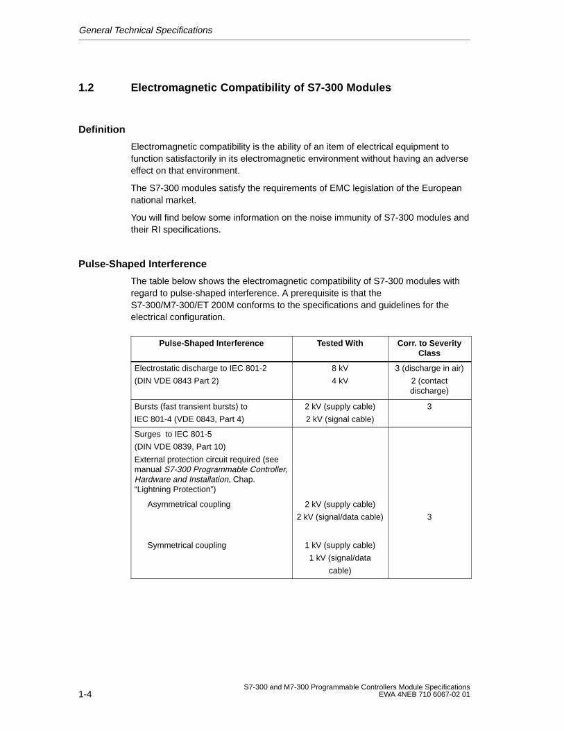
Pulse-Shaped Interference
The table below shows the electromagnetic compatibility of S7-300 modules withregard to pulse-shaped interference. A prerequisite is that theS7-300/M7-300/ET 200M conforms to the specifications and guidelines for theelectrical configuration.
Pulse-Shaped Interference Tested W ith Corr . to SeverityClass
Electrostatic discharge to IEC 801-2
(DIN VDE 0843 Part 2)
8 kV
4 kV
3 (discharge in air)
2 (contactdischarge)
Bursts (fast transient bursts) to
IEC 801-4 (VDE 0843, Part 4)
2 kV (supply cable)
2 kV (signal cable)
3
Surges to IEC 801-5
(DIN VDE 0839, Part 10)
External protection circuit required (seemanual S7-300 Programmable Controller,Hardware and Installation, Chap.“Lightning Protection”)
Asymmetrical coupling 2 kV (supply cable)
2 kV (signal/data cable) 3
Symmetrical coupling 1 kV (supply cable)
1 kV (signal/data
cable)
General Technical Specifications
1-5S7-300 and M7-300 Programmable Controllers Module SpecificationsEWA 4NEB 710 6067-02 01
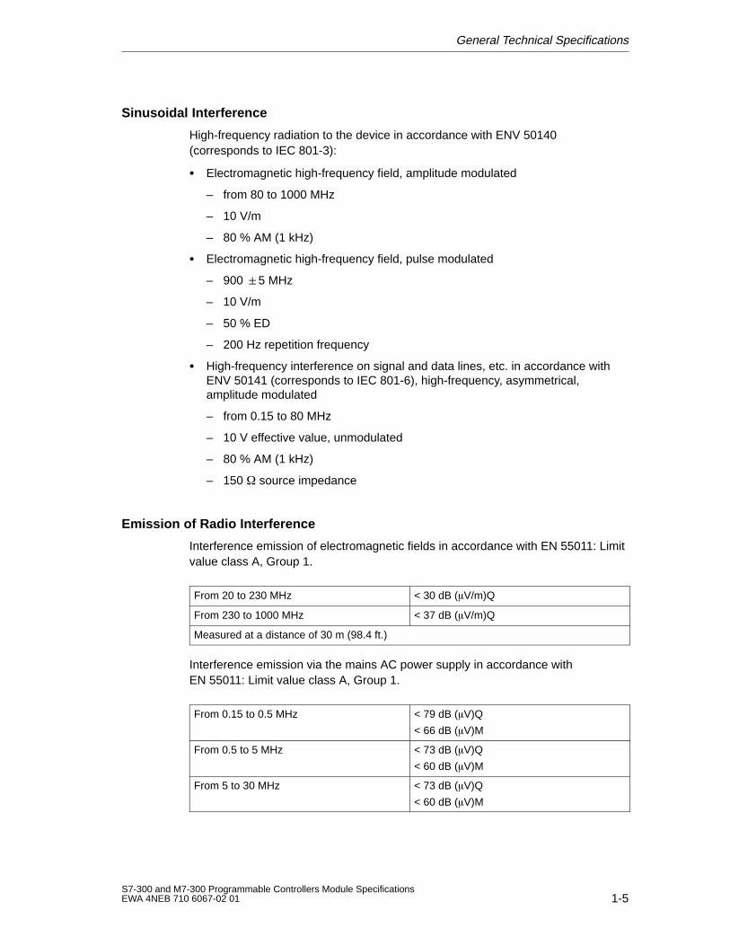
Sinusoidal Interference
High-frequency radiation to the device in accordance with ENV 50140(corresponds to IEC 801-3):
Electromagnetic high-frequency field, amplitude modulated
– from 80 to 1000 MHz
– 10 V/m
– 80 % AM (1 kHz)
Electromagnetic high-frequency field, pulse modulated
– 900 5 MHz
– 10 V/m
– 50 % ED
– 200 Hz repetition frequency
High-frequency interference on signal and data lines, etc. in accordance withENV 50141 (corresponds to IEC 801-6), high-frequency, asymmetrical,amplitude modulated
– from 0.15 to 80 MHz
– 10 V effective value, unmodulated
– 80 % AM (1 kHz)
– 150 source impedance
Emission of Radio Interference
Interference emission of electromagnetic fields in accordance with EN 55011: Limitvalue class A, Group 1.
From 20 to 230 MHz < 30 dB (V/m)Q
From 230 to 1000 MHz < 37 dB (V/m)Q
Measured at a distance of 30 m (98.4 ft.)
Interference emission via the mains AC power supply in accordance withEN 55011: Limit value class A, Group 1.
From 0.15 to 0.5 MHz < 79 dB (V)Q
< 66 dB (V)M
From 0.5 to 5 MHz < 73 dB (V)Q
< 60 dB (V)M
From 5 to 30 MHz < 73 dB (V)Q
< 60 dB (V)M
General Technical Specifications
1-6S7-300 and M7-300 Programmable Controllers Module Specifications
EWA 4NEB 710 6067-02 01
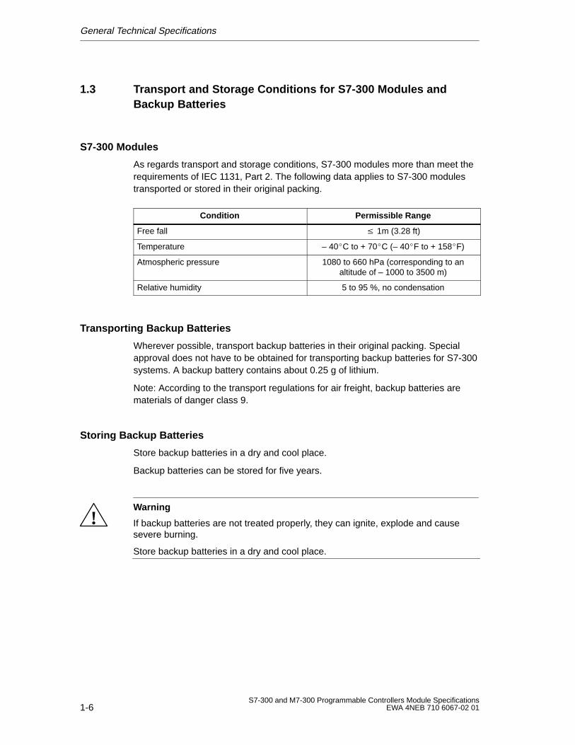
1.3 Transport and Storage Conditions for S7-300 Modules andBackup Batteries
S7-300 Modules
As regards transport and storage conditions, S7-300 modules more than meet therequirements of IEC 1131, Part 2. The following data applies to S7-300 modulestransported or stored in their original packing.
Condition Permissible Range
Free fall 1m (3.28 ft)
Temperature – 40C to + 70C (– 40F to + 158F)
Atmospheric pressure 1080 to 660 hPa (corresponding to analtitude of – 1000 to 3500 m)
Relative humidity 5 to 95 %, no condensation
Transporting Backup Batteries
Wherever possible, transport backup batteries in their original packing. Specialapproval does not have to be obtained for transporting backup batteries for S7-300systems. A backup battery contains about 0.25 g of lithium.
Note: According to the transport regulations for air freight, backup batteries arematerials of danger class 9.
Storing Backup Batteries
Store backup batteries in a dry and cool place.
Backup batteries can be stored for five years.
!Warning
If backup batteries are not treated properly, they can ignite, explode and causesevere burning.
Store backup batteries in a dry and cool place.
General Technical Specifications
1-7S7-300 and M7-300 Programmable Controllers Module SpecificationsEWA 4NEB 710 6067-02 01
1.4 Mechanical and Climatic Environmental Conditions forOperating S7-300s
Operating Conditions
S7-300 systems are intended for stationary use in locations protected against theweather. The operating conditions exceed the requirements of IEC 1131-2.
The S7-300 fulfills the operating conditions of class 3C3 according to DINEN 60721 3-3 (installation locations with high traffic density and in immediateproximity to industrial plants with chemical emissions).
Where Not to Use S7-300 Systems
Unless the appropriate extra measures are taken, S7-300 systems must not beused
in locations exposed to a high degree of ionizing radiation
in hostile environments caused, for instance, by
– dust accumulation
– corrosive vapors or gases.
in installations requiring special monitoring, for example
– elevators
– electrical installations in particularly hazardous locations.
One of the extra measures you can take to widen the application of S7-300systems, for instance, is to install them in cabinets.
General Technical Specifications
1-8S7-300 and M7-300 Programmable Controllers Module Specifications
EWA 4NEB 710 6067-02 01
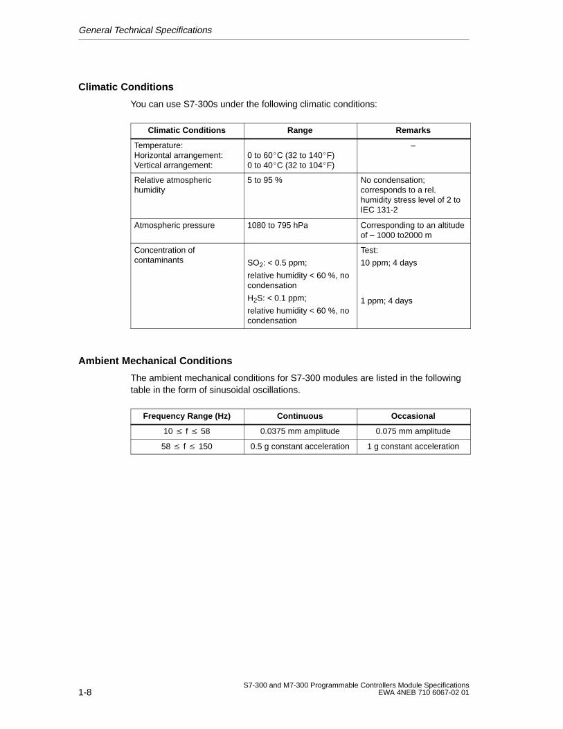
Climatic Conditions
You can use S7-300s under the following climatic conditions:
Climatic Conditions Range Remarks
Temperature:Horizontal arrangement:Vertical arrangement:
0 to 60C (32 to 140F)0 to 40C (32 to 104F)
–
Relative atmospheric humidity
5 to 95 % No condensation;corresponds to a rel.humidity stress level of 2 toIEC 131-2
Atmospheric pressure 1080 to 795 hPa Corresponding to an altitudeof – 1000 to2000 m
Concentration ofcontaminants SO2: < 0.5 ppm;
relative humidity < 60 %, nocondensation
H2S: < 0.1 ppm;
relative humidity < 60 %, nocondensation
Test:
10 ppm; 4 days
1 ppm; 4 days
Ambient Mechanical Conditions
The ambient mechanical conditions for S7-300 modules are listed in the followingtable in the form of sinusoidal oscillations.
Frequency Range (Hz) Continuous Occasional
10 f 58 0.0375 mm amplitude 0.075 mm amplitude
58 f 150 0.5 g constant acceleration 1 g constant acceleration
General Technical Specifications
1-9S7-300 and M7-300 Programmable Controllers Module SpecificationsEWA 4NEB 710 6067-02 01
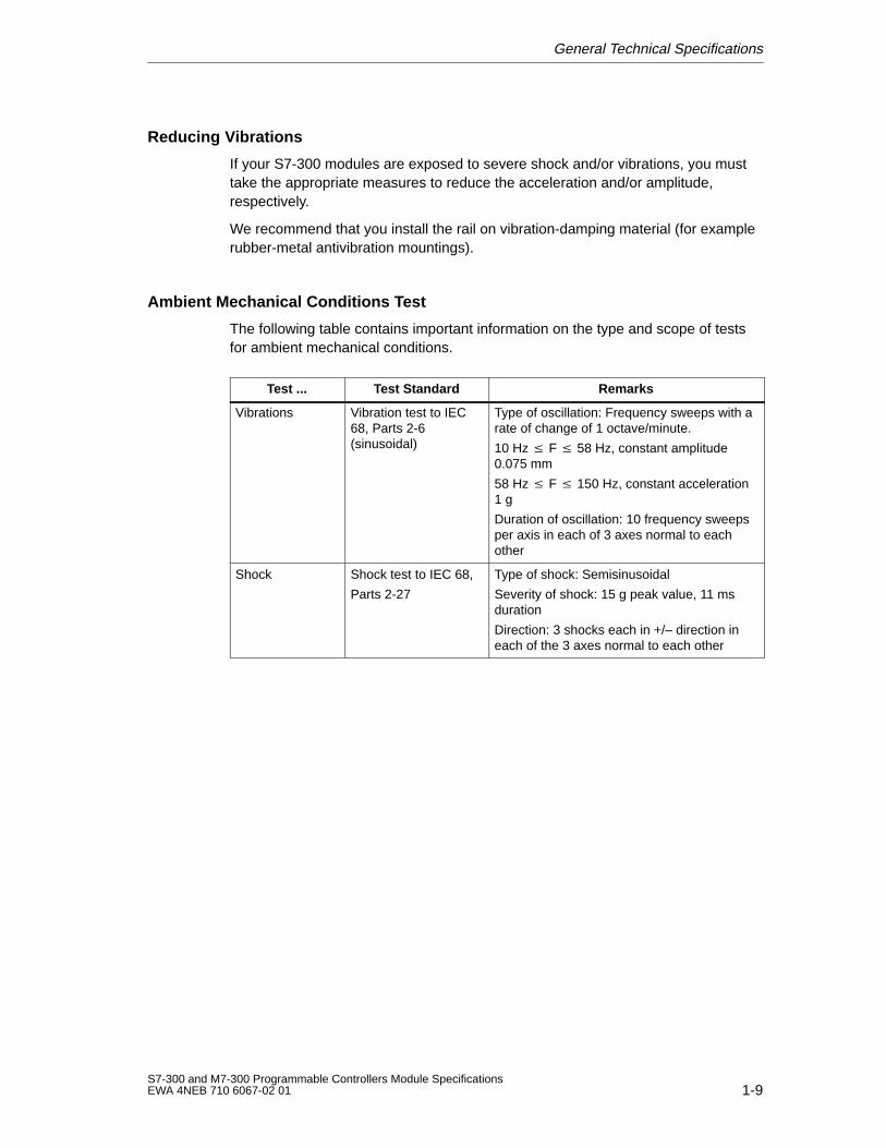
Reducing Vibrations
If your S7-300 modules are exposed to severe shock and/or vibrations, you musttake the appropriate measures to reduce the acceleration and/or amplitude,respectively.
We recommend that you install the rail on vibration-damping material (for examplerubber-metal antivibration mountings).
Ambient Mechanical Conditions Test
The following table contains important information on the type and scope of testsfor ambient mechanical conditions.
Test ... Test Standard Remarks
Vibrations Vibration test to IEC68, Parts 2-6(sinusoidal)
Type of oscillation: Frequency sweeps with arate of change of 1 octave/minute.
10 Hz F 58 Hz, constant amplitude0.075 mm
58 Hz F 150 Hz, constant acceleration1 g
Duration of oscillation: 10 frequency sweepsper axis in each of 3 axes normal to eachother
Shock Shock test to IEC 68,
Parts 2-27
Type of shock: Semisinusoidal
Severity of shock: 15 g peak value, 11 msduration
Direction: 3 shocks each in +/– direction ineach of the 3 axes normal to each other
General Technical Specifications
1-10S7-300 and M7-300 Programmable Controllers Module Specifications
EWA 4NEB 710 6067-02 01
1.5 Information on Insulation Tests, Protection Class and Degree ofProtection
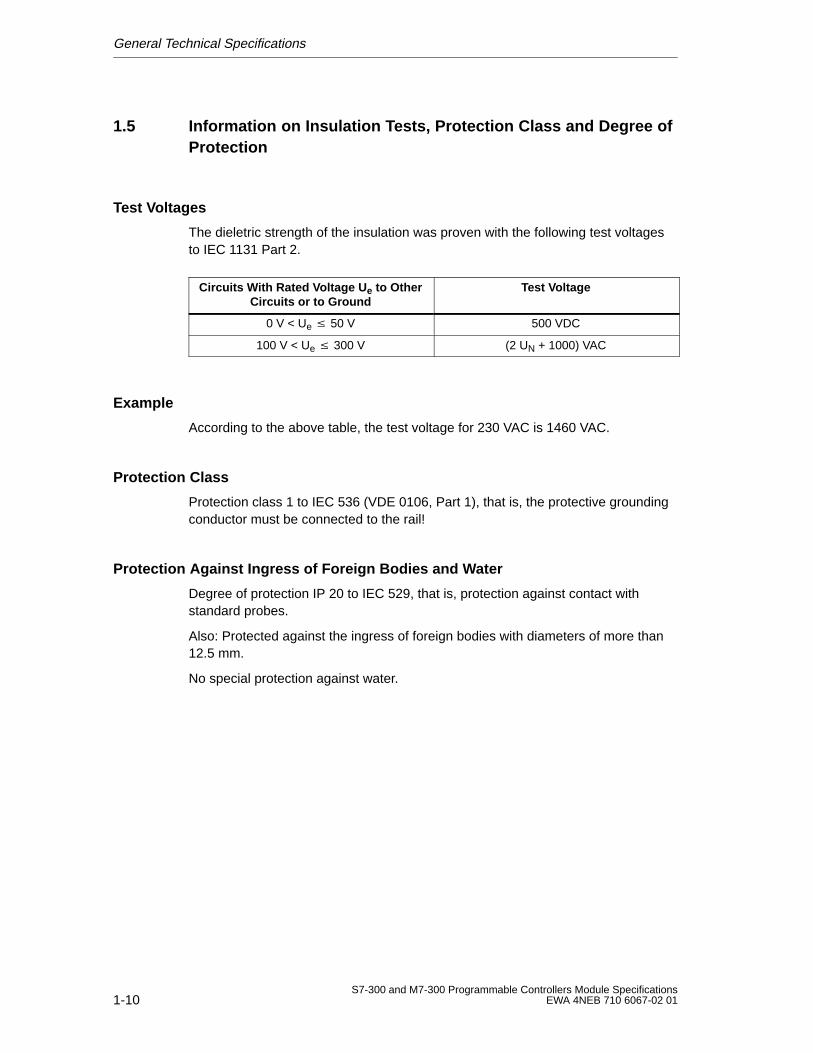
Test Voltages
The dieletric strength of the insulation was proven with the following test voltagesto IEC 1131 Part 2.
Circuits W ith Rated V oltage U e to OtherCircuits or to Ground
Test Voltage
0 V < Ue 50 V 500 VDC
100 V < Ue 300 V (2 UN + 1000) VAC
Example
According to the above table, the test voltage for 230 VAC is 1460 VAC.
Protection Class
Protection class 1 to IEC 536 (VDE 0106, Part 1), that is, the protective groundingconductor must be connected to the rail!
Protection Against Ingress of Foreign Bodies and Water
Degree of protection IP 20 to IEC 529, that is, protection against contact withstandard probes.
Also: Protected against the ingress of foreign bodies with diameters of more than12.5 mm.
No special protection against water.
General Technical Specifications
1-11S7-300 and M7-300 Programmable Controllers Module SpecificationsEWA 4NEB 710 6067-02 01
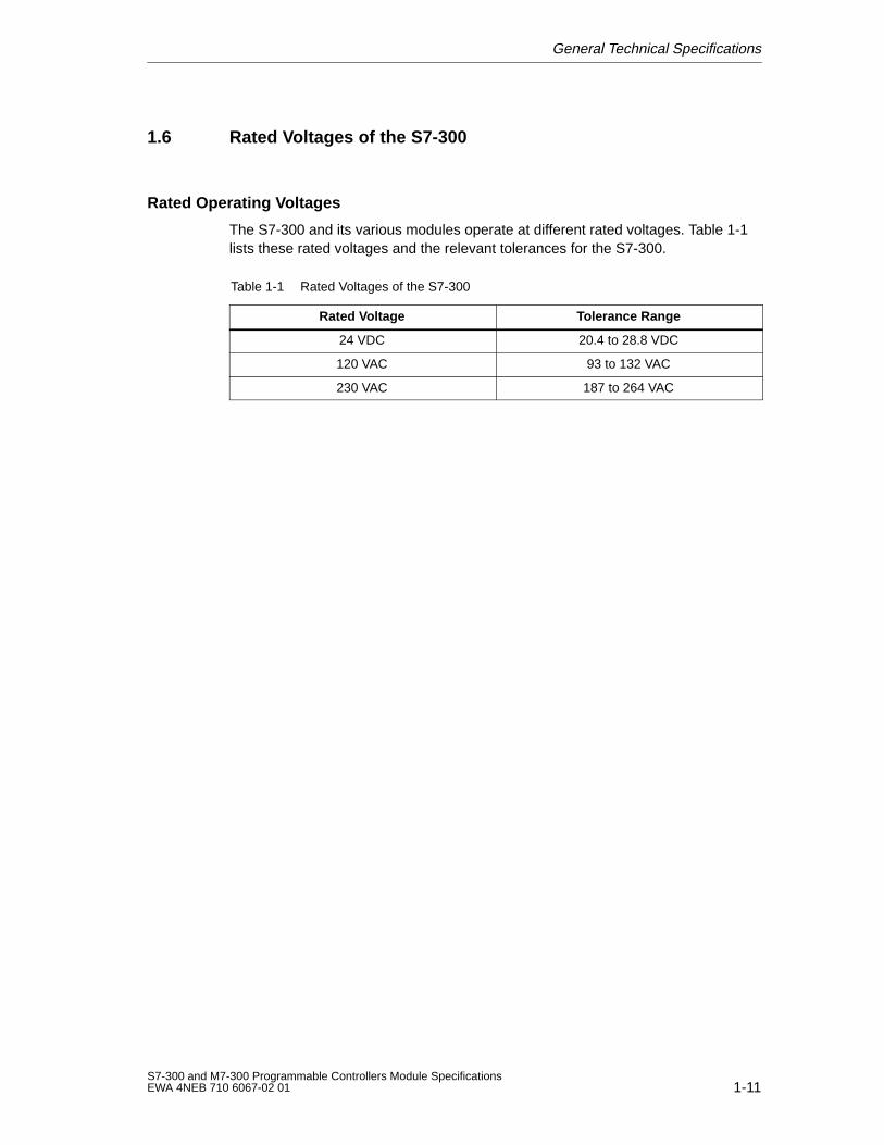
1.6 Rated Voltages of the S7-300
Rated Operating Voltages
The S7-300 and its various modules operate at different rated voltages. Table 1-1lists these rated voltages and the relevant tolerances for the S7-300.
Table 1-1 Rated Voltages of the S7-300
Rated Voltage Tolerance Range
24 VDC 20.4 to 28.8 VDC
120 VAC 93 to 132 VAC
230 VAC 187 to 264 VAC
General Technical Specifications
1-12S7-300 and M7-300 Programmable Controllers Module Specifications
EWA 4NEB 710 6067-02 01
1.7 SIMATIC Outdoor Modules
SIMATIC outdoor modules are modules that can be used under extendedenvironmental conditions. Extended environmental conditions means:
operation possible at temperatures from – 25 °C to + 60 °C
occasional, brief condensation permitted
increased mechanical stress permissible
Comparison with “standard” modules
The functional scope and technical specifications for the SIMATIC outdoormodules correspond to those of the “standard” modules.
The climatic and mechanical environmental conditions as well as the methodsused to test them have changed.
The SIMATIC outdoor modules have their own Order Numbers (see Table 1–1)
Configuring in STEP 7
Do you have a STEP 7 version in which the SIMATIC outdoor modules are not inthe hardware catalog?
Simply configure your system with the corresponding “standard” modules (seeTable 1-2).
General Technical Specifications
1-13S7-300 and M7-300 Programmable Controllers Module SpecificationsEWA 4NEB 710 6067-02 01
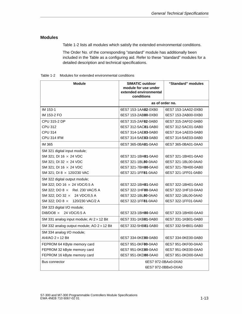
Modules
Table 1-2 lists all modules which satisfy the extended environmental conditions.
The Order No. of the corresponding ”standard” module has additionally beenincluded in the Table as a configuring aid. Refer to these ”standard” modules for adetailed description and technical specifications.
Table 1-2 Modules for extended environmental conditions
Module SIMATIC outdoormodule for use under
extended environmentalconditions
“Standard” modules
as of order no.
IM 153-1
IM 153-2 FO
6ES7 153-1AA82-0XB0
6ES7 153-2AB80-0XB0
6ES7 153-1AA02-0XB0
6ES7 153-2AB00-0XB0
CPU 315-2 DP
CPU 312
CPU 314
CPU 314 IFM
6ES7 315-2AF82-0AB0
6ES7 312-5AC81-0AB0
6ES7 314-1AE83-0AB0
6ES7 314-5AE83-0AB0
6ES7 315-2AF02-0AB0
6ES7 312-5AC01-0AB0
6ES7 314-1AE03-0AB0
6ES7 314-5AE03-0AB0
IM 365 6ES7 365-0BA81-0AA0 6ES7 365-0BA01-0AA0
SM 321 digital input module;
SM 321; DI 16 24 VDC
SM 321; DI 32 24 VDC
SM 321; DI 16 24 VDC
SM 321; DI 8 120/230 VAC
6ES7 321-1BH81-0AA0
6ES7 321-1BL80-0AA0
6ES7 321-7BH80-0AA0
6ES7 321-1FF81-0AA0
6ES7 321-1BH01-0AA0
6ES7 321-1BL00-0AA0
6ES7 321-7BH00-0AB0
6ES7 321-1FF01-0AB0
SM 322 digital output module;
SM 322; DO 16 24 VDC/0.5 A
SM 322; DO 8 Rel. 230 VAC/5 A
SM 322; DO 32 24 VDC/0,5 A
SM 322; DO 8 120/230 VAC/2 A
6ES7 322-1BH81-0AA0
6ES7 322-1HF80-0AA0
6ES7 322-1BL80-0AA0
6ES7 322-1FF81-0AA0
6ES7 322-1BH01-0AA0
6ES7 322-1HF10-0AA0
6ES7 322-1BL00-0AA0
6ES7 322-1FF01-0AA0
SM 323 digital I/O module;
DI8/DO8 24 VDC/0.5 A 6ES7 323-1BH80-0AA0 6ES7 323-1BH00-0AA0
SM 331 analog input module; AI 212 Bit 6ES7 331-1KB81-0AB0 6ES7 331-1KB01-0AB0
SM 332 analog output module; AO 212 Bit 6ES7 332-5HB81-0AB0 6ES7 332-5HB01-0AB0
SM 334 analog I/O module;
AI4/AO 212 Bit 6ES7 334-0KE80-0AB0 6ES7 334-0KE00-0AB0
FEPROM 64 KByte memory card
FEPROM 32 kByte memory card
FEPROM 16 kByte memory card
6ES7 951-0KF80-0AA0
6ES7 951-0KE80-0AA0
6ES7 951-0KD80-0AA0
6ES7 951-0KF00-0AA0
6ES7 951-0KE00-0AA0
6ES7 951-0KD00-0AA0
Bus connector 6ES7 972-0BAx0-0XA0
6ES7 972-0BBx0-0XA0
General Technical Specifications
1-14S7-300 and M7-300 Programmable Controllers Module Specifications
EWA 4NEB 710 6067-02 01
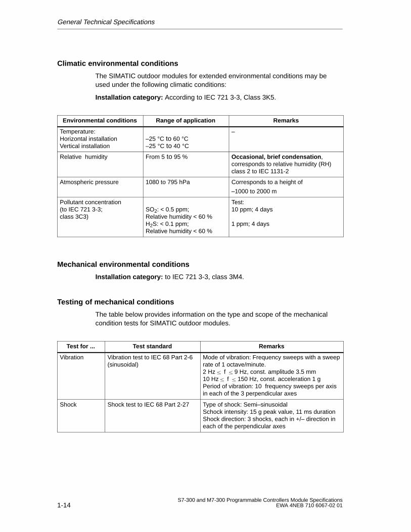
Climatic environmental conditions
The SIMATIC outdoor modules for extended environmental conditions may beused under the following climatic conditions:
Installation category: According to IEC 721 3-3, Class 3K5.
Environmental conditions Range of application Remarks
Temperature:Horizontal installationVertical installation
–25 °C to 60 °C–25 °C to 40 °C
–
Relative humidity From 5 to 95 % Occasional, brief condensation ,corresponds to relative humidity (RH)class 2 to IEC 1131-2
Atmospheric pressure 1080 to 795 hPa Corresponds to a height of
–1000 to 2000 m
Pollutant concentration(to IEC 721 3-3; class 3C3)
SO2: < 0.5 ppm;Relative humidity < 60 %H2S: < 0.1 ppm;Relative humidity < 60 %
Test:10 ppm; 4 days 1 ppm; 4 days
Mechanical environmental conditions
Installation category: to IEC 721 3-3, class 3M4.
Testing of mechanical conditions
The table below provides information on the type and scope of the mechanicalcondition tests for SIMATIC outdoor modules.
Test for ... Test standard Remarks
Vibration Vibration test to IEC 68 Part 2-6(sinusoidal)
Mode of vibration: Frequency sweeps with a sweeprate of 1 octave/minute.2 Hz f 9 Hz, const. amplitude 3.5 mm 10 Hz f 150 Hz, const. acceleration 1 gPeriod of vibration: 10 frequency sweeps per axisin each of the 3 perpendicular axes
Shock Shock test to IEC 68 Part 2-27 Type of shock: Semi–sinusoidalSchock intensity: 15 g peak value, 11 ms durationShock direction: 3 shocks, each in +/– direction ineach of the perpendicular axes
2-1S7-300 and M7-300 Programmable Controllers Module SpecificationsEWA 4NEB 710 6067-02 01
Power Supply Modules
Introduction
Various power supply modules are available to supply your S7-300 programmablecontroller and the sensors/actuactors with 24 VDC.
Power Supply Modules
This chapter describes the technical specifications of the power supply modules ofthe S7-300 programmable controller.
In addition to the technical specifications, this chapter describes the following:
Characteristics
Wiring schematic
Basic circuit diagram
Line protection
Reaction to atypical operating conditions
Contents
This chapter describes the following power supply modules:
Section Contents Page
2.1 Power supply module PS 307; 2 A 2-2
2.2 Power supply module PS 307; 5 A 2-6
2.3 Power supply module PS 307; 10 A 2-11
2
Power Supply Modules
2-2S7-300 and M7-300 Programmable Controllers Module Specifications
EWA 4NEB 710 6067-02 01
2.1 The PS 307 Power Supply Module (2 A)
Order Number
6ES7 307-1BA00-0AA0
Characteristics
The PS 307 power supply module (2 A) has the following salient features:
Output current 2 A
Output voltage 24 VDC; proof against short-circuit and open circuit
Connection to single-phase AC system
(input voltage 120/230 VAC, 50/60 Hz)
Reliable isolation to EN 60 950
Can be used as load power supply
Power Supply Modules
2-3S7-300 and M7-300 Programmable Controllers Module SpecificationsEWA 4NEB 710 6067-02 01
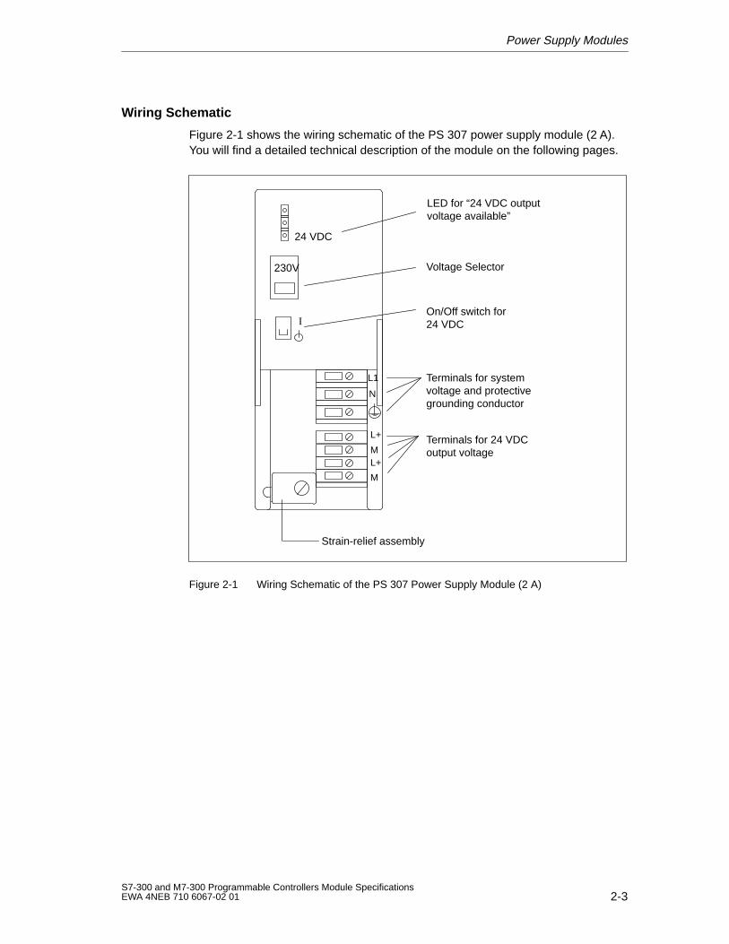
Wiring Schematic
Figure 2-1 shows the wiring schematic of the PS 307 power supply module (2 A).You will find a detailed technical description of the module on the following pages.
Strain-relief assembly
230V
Terminals for systemvoltage and protectivegrounding conductor
Terminals for 24 VDCoutput voltage
Voltage Selector
On/Off switch for24 VDC
24 VDC
L1
N
L+M
M
LED for “24 VDC outputvoltage available”
L+
I
Figure 2-1 Wiring Schematic of the PS 307 Power Supply Module (2 A)
Power Supply Modules
2-4S7-300 and M7-300 Programmable Controllers Module Specifications
EWA 4NEB 710 6067-02 01
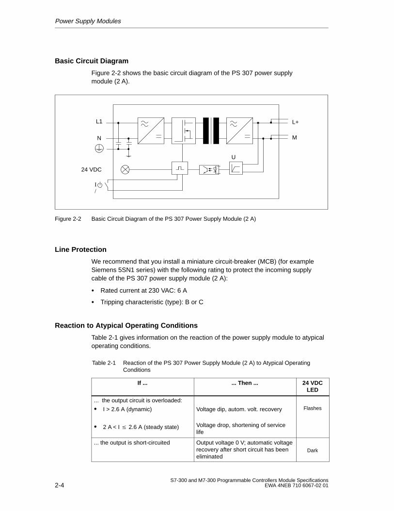
Basic Circuit Diagram
Figure 2-2 shows the basic circuit diagram of the PS 307 power supplymodule (2 A).
L+
M
L1
N
24 VDC
I/
U
Figure 2-2 Basic Circuit Diagram of the PS 307 Power Supply Module (2 A)
Line Protection
We recommend that you install a miniature circuit-breaker (MCB) (for exampleSiemens 5SN1 series) with the following rating to protect the incoming supplycable of the PS 307 power supply module (2 A):
Rated current at 230 VAC: 6 A
Tripping characteristic (type): B or C
Reaction to Atypical Operating Conditions
Table 2-1 gives information on the reaction of the power supply module to atypicaloperating conditions.
Table 2-1 Reaction of the PS 307 Power Supply Module (2 A) to Atypical OperatingConditions
If ... ... Then ... 24 VDCLED
... the output circuit is overloaded:
I > 2.6 A (dynamic)
2 A < I 2.6 A (steady state)
Voltage dip, autom. volt. recovery
Voltage drop, shortening of servicelife
Flashes
... the output is short-circuited Output voltage 0 V; automatic voltagerecovery after short circuit has beeneliminated
Dark
Power Supply Modules
2-5S7-300 and M7-300 Programmable Controllers Module SpecificationsEWA 4NEB 710 6067-02 01
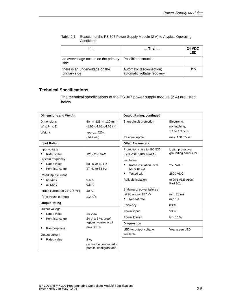
Table 2-1 Reaction of the PS 307 Power Supply Module (2 A) to Atypical OperatingConditions
If ... 24 VDCLED
... Then ...
an overvoltage occurs on the primaryside
Possible destruction -
there is an undervoltage on theprimary side
Automatic disconnection; automatic voltage recovery
Dark
Technical Specifications
The technical specifications of the PS 307 power supply module (2 A) are listedbelow.
Dimensions and Weight
Dimensions
W H D
50 125 120 mm
(1.954.884.68 in.)
Weight approx. 420 g
(14.7 oz.)
Input Rating
Input voltage
Rated value
System frequency
Rated value
Permiss. range
120 / 230 VAC
50 Hz or 60 Hz
47 Hz to 63 Hz
Rated input current
at 230 V
at 120 V
0.5 A
0.8 A
Inrush current (at 25°C/77°F) 20 A
I2t (at inrush current) 2.2 A2s
Output Rating
Output voltage
Rated value
Permiss. range
Ramp-up time
24 VDC
24 V 5 %, proofagainst open-circuit
max. 2.5 s
Output current
Rated value
2 A,
cannot be connected inparallel configurations
Output Rating, continued
Short-circuit protection Electronic,
nonlatching,
1.1 to 1.3 IN
Residual ripple max. 150 mVss
Other Parameters
Protection class to IEC 536
(DIN VDE 0106, Part 1)
I, with protectivegrounding conductor
Insulation
Rated insulation level(24 V to L1)
Tested with
250 VAC
2800 VDC
Reliable isolation to DIN VDE 0106,Part 101
Bridging of power failures
(at 93 and/or 187 V)
Repeat rate
min. 20 ms
min 1 s
Efficiency 83 %
Power input 58 W
Power losses typ. 10 W
Diagnostics
LED for output voltage
available
Yes, green LED
Power Supply Modules
2-6S7-300 and M7-300 Programmable Controllers Module Specifications
EWA 4NEB 710 6067-02 01
2.2 The PS 307 Power Supply Module (5 A)
Order Number
6ES7 307-1EA00-0AA0
Eigenschaften
The PS 307 power supply module (5 A) has the following salient features:
Output current 5 A
Output voltage 24 VDC; proof against short-circuit and open circuit
Connection to single-phase AC system
(input voltage 120/230 VAC, 50/60 Hz)
Safe electrical isolation to EN 60 950
Can be used as load power supply
Power Supply Modules
2-7S7-300 and M7-300 Programmable Controllers Module SpecificationsEWA 4NEB 710 6067-02 01
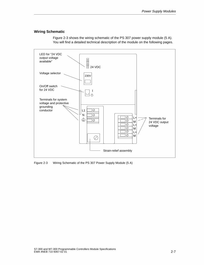
Wiring Schematic
Figure 2-3 shows the wiring schematic of the PS 307 power supply module (5 A).You will find a detailed technical description of the module on the following pages.
Strain-relief assembly
Terminals for system voltage and protectivegrounding conductor
Terminals for 24 VDC outputvoltage
LED for “24 VDCoutput voltage available”
Voltage selector
On/Off switchfor 24 VDC
230V
24 VDC
L1
NL+
L+
L+
M
M
M
I
Figure 2-3 Wiring Schematic of the PS 307 Power Supply Module (5 A)
Power Supply Modules
2-8S7-300 and M7-300 Programmable Controllers Module Specifications
EWA 4NEB 710 6067-02 01
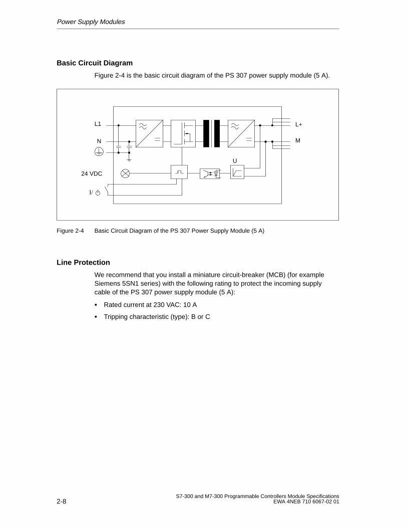
Basic Circuit Diagram
Figure 2-4 is the basic circuit diagram of the PS 307 power supply module (5 A).
L+
M
L1
N
24 VDC
U
I/
Figure 2-4 Basic Circuit Diagram of the PS 307 Power Supply Module (5 A)
Line Protection
We recommend that you install a miniature circuit-breaker (MCB) (for exampleSiemens 5SN1 series) with the following rating to protect the incoming supplycable of the PS 307 power supply module (5 A):
Rated current at 230 VAC: 10 A
Tripping characteristic (type): B or C
Power Supply Modules
2-9S7-300 and M7-300 Programmable Controllers Module SpecificationsEWA 4NEB 710 6067-02 01
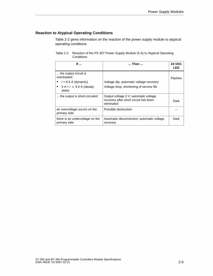
Reaction to Atypical Operating Conditions
Table 2-2 gives information on the reaction of the power supply module to atypicaloperating conditions.
Table 2-2 Reaction of the PS 307 Power Supply Module (5 A) to Atypical OperatingConditions
If ... ... Then ... 24 VDCLED
... the output circuit isoverloaded:
I > 6.5 A (dynamic)
5 A < I 6.5 A (steadystate)
Voltage dip, automatic voltage recovery
Voltage drop, shortening of service life
Flashes
... the output is short-circuited Output voltage 0 V; automatic voltagerecovery after short circuit has beeneliminated
Dark
an overvoltage occurs on theprimary side
Possible destruction –
there is an undervoltage on theprimary side
Automatic disconnection; automatic voltagerecovery
Dark
Power Supply Modules
2-10S7-300 and M7-300 Programmable Controllers Module Specifications
EWA 4NEB 710 6067-02 01
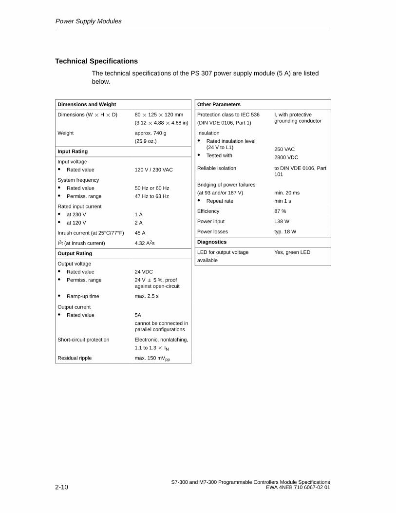
Technical Specifications
The technical specifications of the PS 307 power supply module (5 A) are listedbelow.
Dimensions and Weight
Dimensions (W H D) 80 125 120 mm
(3.12 4.88 4.68 in)
Weight approx. 740 g
(25.9 oz.)
Input Rating
Input voltage
Rated value 120 V / 230 VAC
System frequency
Rated value
Permiss. range
50 Hz or 60 Hz
47 Hz to 63 Hz
Rated input current
at 230 V
at 120 V
1 A
2 A
Inrush current (at 25°C/77°F) 45 A
I2t (at inrush current) 4.32 A2s
Output Rating
Output voltage
Rated value
Permiss. range
Ramp-up time
24 VDC
24 V 5 %, proofagainst open-circuit
max. 2.5 s
Output current
Rated value 5A
cannot be connected inparallel configurations
Short-circuit protection Electronic, nonlatching,
1.1 to 1.3 IN
Residual ripple max. 150 mVpp
Other Parameters
Protection class to IEC 536
(DIN VDE 0106, Part 1)
I, with protectivegrounding conductor
Insulation
Rated insulation level(24 V to L1)
Tested with250 VAC
2800 VDC
Reliable isolation to DIN VDE 0106, Part101
Bridging of power failures
(at 93 and/or 187 V)
Repeat rate
min. 20 ms
min 1 s
Efficiency 87 %
Power input 138 W
Power losses typ. 18 W
Diagnostics
LED for output voltage
available
Yes, green LED
Power Supply Modules
2-11S7-300 and M7-300 Programmable Controllers Module SpecificationsEWA 4NEB 710 6067-02 01
2.3 The PS 307 Power Supply Module (10 A)
Order Number
6ES7 307-1KA00-0AA0
Characteristics
The PS 307 power supply module (10 A) has the following salient features:
Output current 10 A
Output voltage 24 VDC; proof against short-circuit and open circuit
Connection to single-phase AC system
(input voltage 120/230 VAC, 50/60 Hz)
Reliable isolation to EN 60 950
Can be used as load power supply
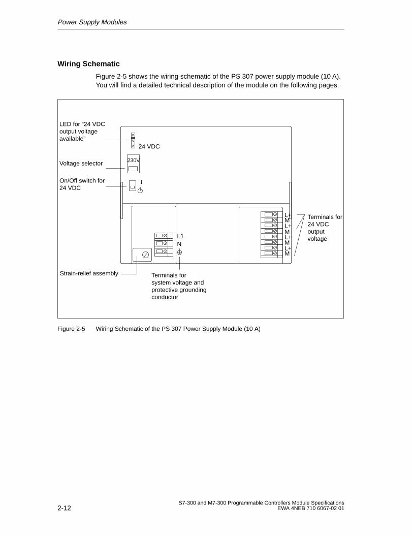
Power Supply Modules
2-12S7-300 and M7-300 Programmable Controllers Module Specifications
EWA 4NEB 710 6067-02 01
Wiring Schematic
Figure 2-5 shows the wiring schematic of the PS 307 power supply module (10 A).You will find a detailed technical description of the module on the following pages.
Terminals forsystem voltage andprotective groundingconductor
Terminals for24 VDC outputvoltage
LED for “24 VDCoutput voltageavailable”
Voltage selector
On/Off switch for24 VDC
230V
24 VDC
L+ML+ML+ML+M
Strain-relief assembly
L1N
I
Figure 2-5 Wiring Schematic of the PS 307 Power Supply Module (10 A)
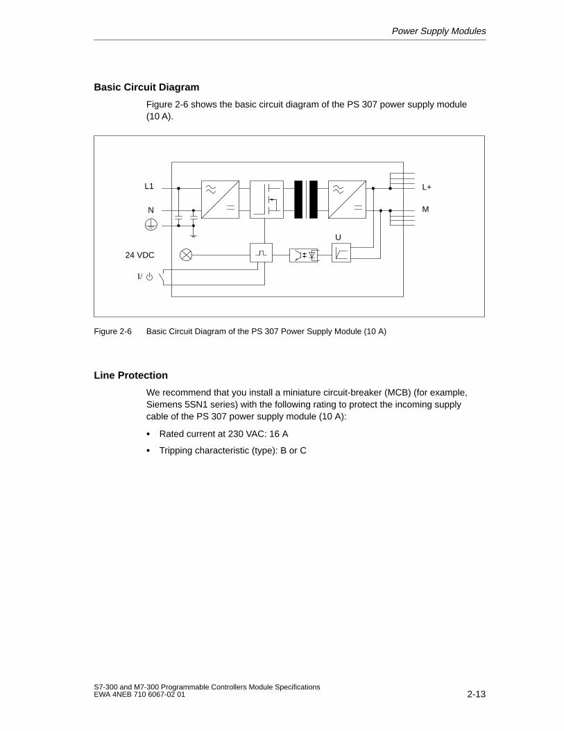
Power Supply Modules
2-13S7-300 and M7-300 Programmable Controllers Module SpecificationsEWA 4NEB 710 6067-02 01
Basic Circuit Diagram
Figure 2-6 shows the basic circuit diagram of the PS 307 power supply module(10 A).
L+
M
L1
N
24 VDC
U
I/
Figure 2-6 Basic Circuit Diagram of the PS 307 Power Supply Module (10 A)
Line Protection
We recommend that you install a miniature circuit-breaker (MCB) (for example,Siemens 5SN1 series) with the following rating to protect the incoming supplycable of the PS 307 power supply module (10 A):
Rated current at 230 VAC: 16 A
Tripping characteristic (type): B or C
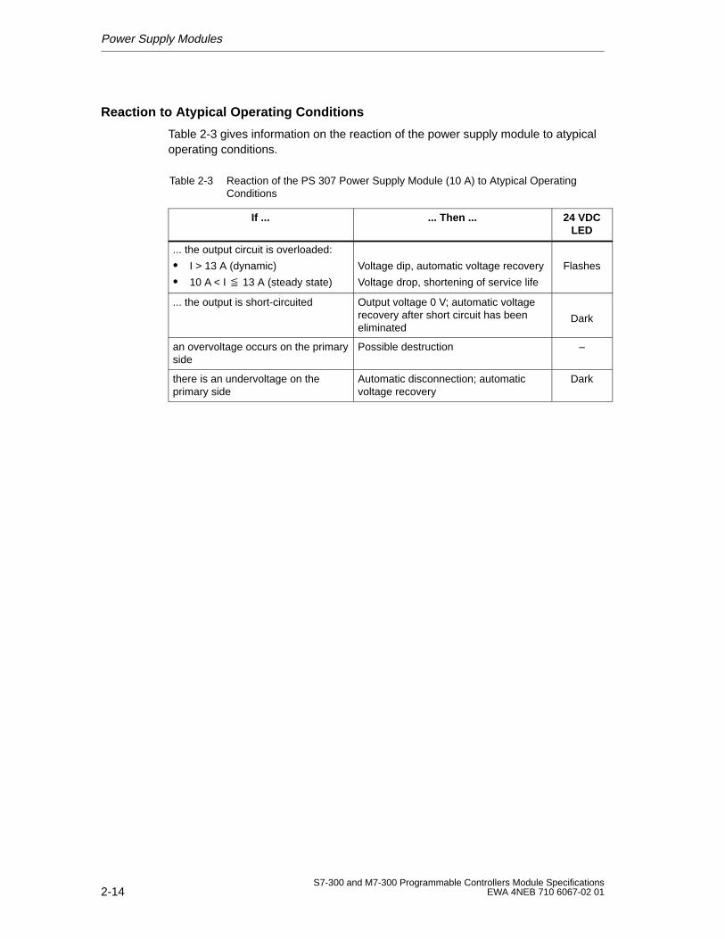
Power Supply Modules
2-14S7-300 and M7-300 Programmable Controllers Module Specifications
EWA 4NEB 710 6067-02 01
Reaction to Atypical Operating Conditions
Table 2-3 gives information on the reaction of the power supply module to atypicaloperating conditions.
Table 2-3 Reaction of the PS 307 Power Supply Module (10 A) to Atypical OperatingConditions
If ... ... Then ... 24 VDCLED
... the output circuit is overloaded:
I > 13 A (dynamic)
10 A < I 13 A (steady state)
Voltage dip, automatic voltage recovery
Voltage drop, shortening of service life
Flashes
... the output is short-circuited Output voltage 0 V; automatic voltagerecovery after short circuit has beeneliminated
Dark
an overvoltage occurs on the primaryside
Possible destruction –
there is an undervoltage on theprimary side
Automatic disconnection; automaticvoltage recovery
Dark
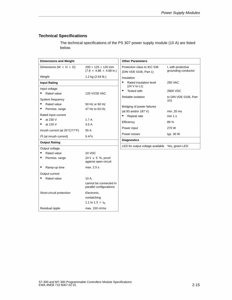
Power Supply Modules
2-15S7-300 and M7-300 Programmable Controllers Module SpecificationsEWA 4NEB 710 6067-02 01
Technical Specifications
The technical specifications of the PS 307 power supply module (10 A) are listedbelow.
Dimensions and Weight
Dimensions (W H D) 200125120 mm(7.8 4.88 4.68 in.)
Weight 1.2 kg (2.64 lb.)
Input Rating
Input voltage
Rated value 120 V/230 VAC
System frequency
Rated value
Permiss. range
50 Hz or 60 Hz
47 Hz to 63 Hz
Rated input current
at 230 V
at 120 V
1.7 A
3.5 A
Inrush current (at 25°C/77°F) 55 A
I2t (at inrush current) 9 A2s
Output Rating
Output voltage
Rated value
Permiss. range
Ramp-up time
24 VDC
24 V 5 %, proofagainst open circuit
max. 2.5 s
Output current
Rated value 10 A,
cannot be connected inparallel configurations
Short-circuit protection Electronic,
nonlatching
1.1 to 1.3 IN
Residual ripple max. 150 mVss
Other Parameters
Protection class to IEC 536
(DIN VDE 0106, Part 1)
I, with protectivegrounding conductor
Insulation
Rated insulation level(24 V to L1)
Tested with
250 VAC
2800 VDC
Reliable isolation to DIN VDE 0106, Part101
Bridging of power failures
(at 93 and/or 187 V)
Repeat rate
min. 20 ms
min 1 s
Efficiency 89 %
Power input 270 W
Power losses typ. 30 W
Diagnostics
LED for output voltage available Yes, green LED

Power Supply Modules
2-16S7-300 and M7-300 Programmable Controllers Module Specifications
EWA 4NEB 710 6067-02 01
3-1S7-300 and M7-300 Programmable Controllers Module SpecificationsEWA 4NEB 710 6067-02 01
Digital Modules
Introduction
A range of digital modules are available for the S7-300 programmable controller toconnect sensors/transducers and/or loads/actuators.
Digital Modules
This chapter contains the technical specifications of the digital modules of theS7-300.
Apart from the technical specifications, this chapter also describes:
The characteristics
The special features
The module view and the block diagram of the digital modules
Contents
This chapter contains the technical specifications for the following groups of digitalmodules:
Section Contents Page
3.1 Digital Input Modules 3-2
3.2 Digital Output Modules 3-31
3.3 Relay Output Modules 3-59
3.4 Digital Input/Output Modules 3-70
3
Digital Modules
3-2S7-300 and M7-300 Programmable Controllers Module Specifications
EWA 4NEB 710 6067-02 01
3.1 Digital Input Modules
List of Digital Input Modules
This chapter describes the following digital input modules:
SM 321; DI 32 24 VDC
SM 321; DI 16 24 VDC
SM 321; DI 16 24 VDC; with process and diagnostics interrupts
SM 321; DI 16 120 VAC
SM 321; DI 8 120/230 VAC
SM 321; DI 16 24 VDC; source input
SM 321; DI 32 120 VAC
3.1.1 Digital Input Module SM 321; DI 32 24 VDC
Order Number
6ES7 321-1BL00-0AA0
Characteristics
The digital input module SM 321; DI 3224 VDC has the following salientfeatures:
32 input points, isolated in groups of 32
24 VDC rated input voltage
Suitable for switches and 2/3/4-wire BEROs (proximity switches).
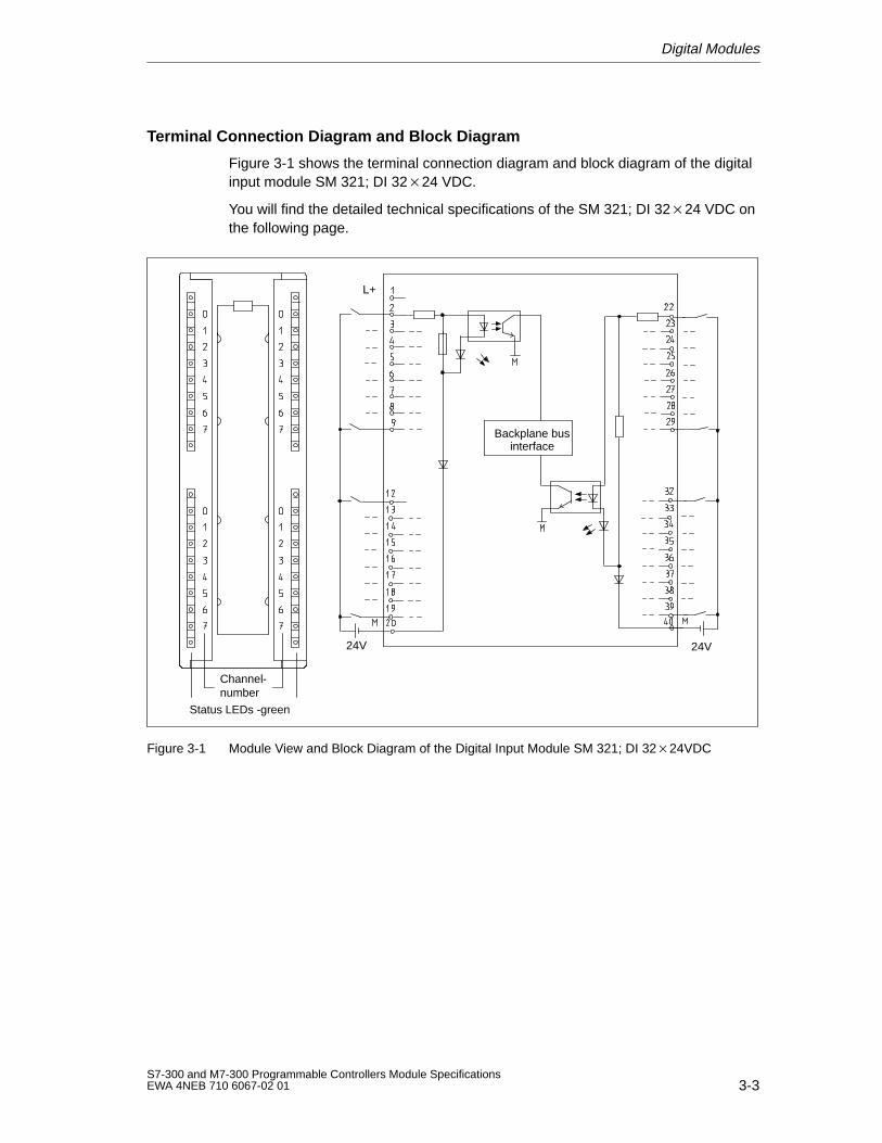
Digital Modules
3-3S7-300 and M7-300 Programmable Controllers Module SpecificationsEWA 4NEB 710 6067-02 01
Terminal Connection Diagram and Block Diagram
Figure 3-1 shows the terminal connection diagram and block diagram of the digitalinput module SM 321; DI 3224 VDC.
You will find the detailed technical specifications of the SM 321; DI 3224 VDC onthe following page.
Channel-number
Status LEDs -green
L+
Backplane businterface
24V 24V
Figure 3-1 Module View and Block Diagram of the Digital Input Module SM 321; DI 3224VDC
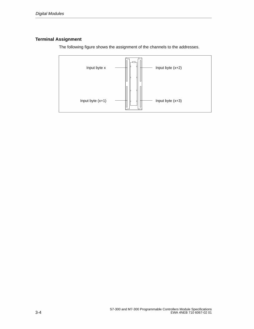
Digital Modules
3-4S7-300 and M7-300 Programmable Controllers Module Specifications
EWA 4NEB 710 6067-02 01
Terminal Assignment
The following figure shows the assignment of the channels to the addresses.
Input byte x
Input byte (x+1)
Input byte (x+2)
Input byte (x+3)
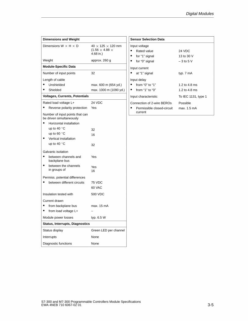
Digital Modules
3-5S7-300 and M7-300 Programmable Controllers Module SpecificationsEWA 4NEB 710 6067-02 01
Dimensions and W eight
Dimensions W H D 40 125 120 mm(1.56 4.88 4.68 in.)
Weight approx. 260 g
Module-Specific Data
Number of input points 32
Length of cable
Unshielded
Shielded
max. 600 m (654 yd.)
max. 1000 m (1090 yd.)
Voltages, Currents, Potentials
Rated load voltage L+
Reverse polarity protection
24 VDC
Yes
Number of input points that canbe driven simultaneously
Horizontal installation
up to 40 C
up to 60 C
Vertical installation
up to 40 C
32
16
32
Galvanic isolation
between channels andbackplane bus
between the channels in groups of
Yes
Yes16
Permiss. potential differences
between different circuits 75 VDC
60 VAC
Insulation tested with 500 VDC
Current drawn
from backplane bus
from load voltage L+
max. 15 mA
–
Module power losses typ. 6.5 W
Status, Interrupts, Diagnostics
Status display Green LED per channel
Interrupts None
Diagnostic functions None
Sensor Selection Data
Input voltage
Rated value
for “1” signal
for “0” signal
24 VDC
13 to 30 V
– 3 to 5 V
Input current
at “1” signal typ. 7 mA
Input delay
from “0” to “1”
from “1” to “0”
1.2 to 4.8 ms
1.2 to 4.8 ms
Input characteristic To IEC 1131, type 1
Connection of 2-wire BEROs
Permissible closed-circuitcurrent
Possible
max. 1.5 mA
Digital Modules
3-6S7-300 and M7-300 Programmable Controllers Module Specifications
EWA 4NEB 710 6067-02 01
3.1.2 Digital Input Module SM 321; DI 16 24 VDC
Order No.
Characteristics
The digital input module SM 321; DI 16 24 VDC has the following salientfeatures:
16 input points, isolated in groups of 16
24 VDC rated input voltage
Suitable for switches and 2/3/4-wire BEROs (proximity switches).
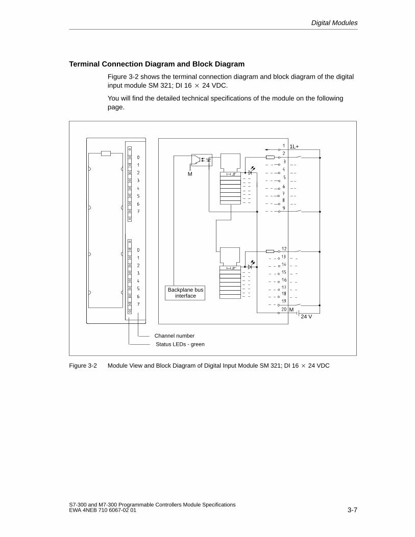
Digital Modules
3-7S7-300 and M7-300 Programmable Controllers Module SpecificationsEWA 4NEB 710 6067-02 01
Terminal Connection Diagram and Block Diagram
Figure 3-2 shows the terminal connection diagram and block diagram of the digitalinput module SM 321; DI 16 24 VDC.
You will find the detailed technical specifications of the module on the followingpage.
Status LEDs - green
Channel number
Backplane businterface
1L+
M
M24 V
Figure 3-2 Module View and Block Diagram of Digital Input Module SM 321; DI 16 24 VDC
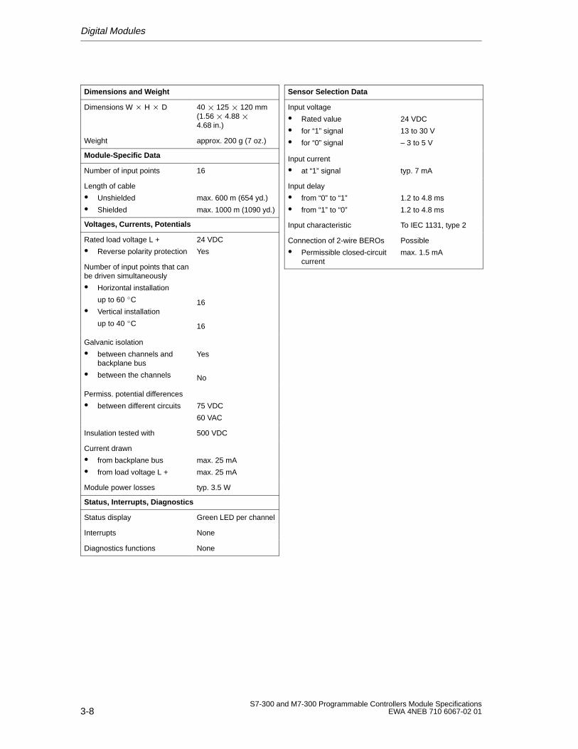
Digital Modules
3-8S7-300 and M7-300 Programmable Controllers Module Specifications
EWA 4NEB 710 6067-02 01
Dimensions and W eight
Dimensions W H D 40 125 120 mm(1.56 4.88 4.68 in.)
Weight approx. 200 g (7 oz.)
Module-Specific Data
Number of input points 16
Length of cable
Unshielded
Shielded
max. 600 m (654 yd.)
max. 1000 m (1090 yd.)
Voltages, Currents, Potentials
Rated load voltage L +
Reverse polarity protection
24 VDC
Yes
Number of input points that canbe driven simultaneously
Horizontal installation
up to 60 C
Vertical installation
up to 40 C
16
16
Galvanic isolation
between channels andbackplane bus
between the channels
Yes
No
Permiss. potential differences
between different circuits 75 VDC
60 VAC
Insulation tested with 500 VDC
Current drawn
from backplane bus
from load voltage L +
max. 25 mA
max. 25 mA
Module power losses typ. 3.5 W
Status, Interrupts, Diagnostics
Status display Green LED per channel
Interrupts None
Diagnostics functions None
Sensor Selection Data
Input voltage
Rated value
for “1” signal
for “0” signal
24 VDC
13 to 30 V
– 3 to 5 V
Input current
at “1” signal typ. 7 mA
Input delay
from “0” to “1”
from “1” to “0”
1.2 to 4.8 ms
1.2 to 4.8 ms
Input characteristic To IEC 1131, type 2
Connection of 2-wire BEROs
Permissible closed-circuitcurrent
Possible
max. 1.5 mA
Digital Modules
3-9S7-300 and M7-300 Programmable Controllers Module SpecificationsEWA 4NEB 710 6067-02 01
3.1.3 Digital Input Module SM 321; DI 16 24 VDC; with Process andDiagnostics Interrupts
Order Number
6ES7 321-7BH00-0AB0
Characteristics
The digital input module SM 321; DI 1624 VDC with process and diagnosticsinterrupts has the following salient features:
16 input points, isolated in groups of 16
24 VDC rated input voltage
Suitable for switches and 2/3/4-wire BEROs (proximity switches)
2 short-circuit-proof sensor supplies for 8 channels each
External redundant power supply possible for sensors
“Sensor supply (Vs) O.K.” status LEDs
Group fault LED
Configurable diagnostics
Configurable diagnostics interrupt
Configurable process interrupt
Settable input delays
Use in
This I/O modules can be used in the
S7-300 (centralized configuration) with the CPU312 IFM from 6ES7 312-5AC00-0AB0, revision level 5313 from 6ES7 313-1AD00-0AB0, revision level 3314 from 6ES7 314-1AE01-0AB0, revision level 6314 IFM from 6ES7 314-5AE00-0AB0, revision level 1315 from 6ES7 315-1AF00-0AB0, revision level 3315-2 from 6ES7 315-2AF00-0AB0, revision level 3614 from 6ES7 614-1AH01-0AB3, revision level 6.
ET 200M with theIM 153-1 from 6ES7 153-1AA02-0XB0, revision level 1IM 153-2 from 6ES7 153-2Ax00-0XB0, revision level 1IM 153-3 from 6ES7 153-3AA00-0XB0, revision level 1and with the following DP masters :IM 308C from 6ES5 308-3UC11, revision level 3, andCPUs 41x from 6ES7 41x-2XG00-0AB0; revision level 2.
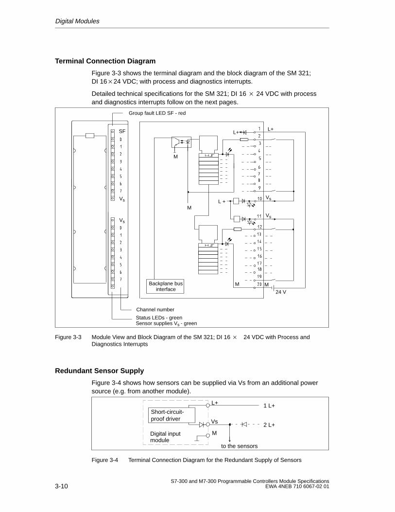
Digital Modules
3-10S7-300 and M7-300 Programmable Controllers Module Specifications
EWA 4NEB 710 6067-02 01
Terminal Connection Diagram
Figure 3-3 shows the terminal diagram and the block diagram of the SM 321;DI 1624 VDC; with process and diagnostics interrupts.
Detailed technical specifications for the SM 321; DI 16 24 VDC with processand diagnostics interrupts follow on the next pages.
Status LEDs - green
Channel number
Backplane businterface
L+
M
M24 V
Group fault LED SF - red
SF
Vs
Vs
Sensor supplies Vs - green
M
M
L+
Vs
Vs
L +
Figure 3-3 Module View and Block Diagram of the SM 321; DI 16 24 VDC with Process andDiagnostics Interrupts
Redundant Sensor Supply
Figure 3-4 shows how sensors can be supplied via Vs from an additional powersource (e.g. from another module).
Vs
M
L+ 1 L+
2 L+
to the sensors
Digital inputmodule
Short-circuit-proof driver
Figure 3-4 Terminal Connection Diagram for the Redundant Supply of Sensors
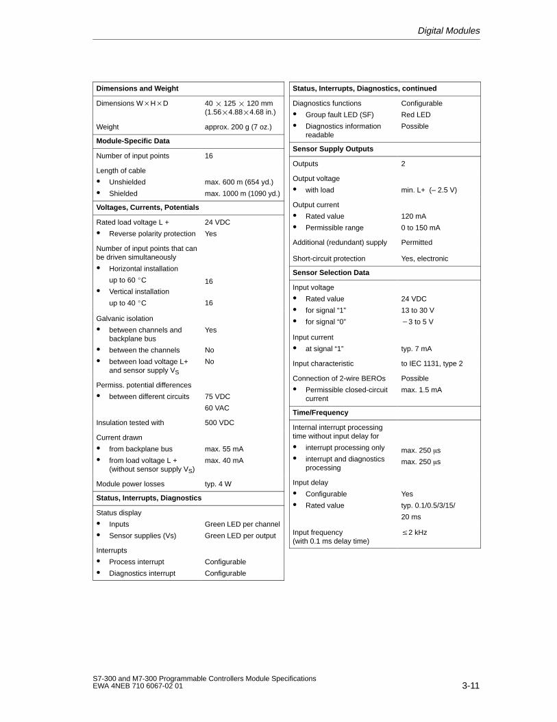
Digital Modules
3-11S7-300 and M7-300 Programmable Controllers Module SpecificationsEWA 4NEB 710 6067-02 01
Dimensions and W eight
Dimensions WHD 40 125 120 mm(1.564.884.68 in.)
Weight approx. 200 g (7 oz.)
Module-Specific Data
Number of input points 16
Length of cable
Unshielded
Shielded
max. 600 m (654 yd.)
max. 1000 m (1090 yd.)
Voltages, Currents, Potentials
Rated load voltage L +
Reverse polarity protection
24 VDC
Yes
Number of input points that canbe driven simultaneously
Horizontal installation
up to 60 C
Vertical installation
up to 40 C
16
16
Galvanic isolation
between channels andbackplane bus
between the channels
between load voltage L+and sensor supply VS
Yes
No
No
Permiss. potential differences
between different circuits 75 VDC
60 VAC
Insulation tested with 500 VDC
Current drawn
from backplane bus
from load voltage L +(without sensor supply VS)
max. 55 mA
max. 40 mA
Module power losses typ. 4 W
Status, Interrupts, Diagnostics
Status display
Inputs
Sensor supplies (Vs)
Green LED per channel
Green LED per output
Interrupts
Process interrupt
Diagnostics interrupt
Configurable
Configurable
Status, Interrupts, Diagnostics, continued
Diagnostics functions
Group fault LED (SF)
Diagnostics informationreadable
Configurable
Red LED
Possible
Sensor Supply Outputs
Outputs 2
Output voltage
with load min. L+ (– 2.5 V)
Output current
Rated value
Permissible range
120 mA
0 to 150 mA
Additional (redundant) supply Permitted
Short-circuit protection Yes, electronic
Sensor Selection Data
Input voltage
Rated value
for signal “1”
for signal “0”
24 VDC
13 to 30 V
3 to 5 V
Input current
at signal “1” typ. 7 mA
Input characteristic to IEC 1131, type 2
Connection of 2-wire BEROs
Permissible closed-circuitcurrent
Possible
max. 1.5 mA
Time/Frequency
Internal interrupt processingtime without input delay for
interrupt processing only
interrupt and diagnosticsprocessing
max. 250 s
max. 250 s
Input delay
Configurable
Rated value
Yes
typ. 0.1/0.5/3/15/
20 ms
Input frequency(with 0.1 ms delay time)
2 kHz
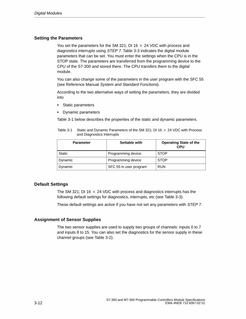
Digital Modules
3-12S7-300 and M7-300 Programmable Controllers Module Specifications
EWA 4NEB 710 6067-02 01
Setting the Parameters
You set the parameters for the SM 321; DI 16 24 VDC with process anddiagnostics interrupts using STEP 7. Table 3-3 indicates the digital moduleparameters that can be set. You must enter the settings when the CPU is in theSTOP state. The parameters are transferred from the programming device to theCPU of the S7-300 and stored there. The CPU transfers them to the digitalmodule.
You can also change some of the parameters in the user program with the SFC 55(see Reference Manual System and Standard Functions).
According to the two alternative ways of setting the parameters, they are dividedinto
Static parameters
Dynamic parameters
Table 3-1 below describes the properties of the static and dynamic parameters.
Table 3-1 Static and Dynamic Parameters of the SM 321; DI 16 24 VDC with Processand Diagnostics Interrupts
Parameter Settable with Operating State of theCPU
Static Programming device STOP
Dynamic Programming device STOP
Dynamic SFC 55 in user program RUN
Default Settings
The SM 321; DI 16 24 VDC with process and diagnostics interrupts has thefollowing default settings for diagnostics, interrupts, etc (see Table 3-3).
These default settings are active if you have not set any parameters with STEP 7.
Assignment of Sensor Supplies
The two sensor supplies are used to supply two groups of channels: inputs 0 to 7and inputs 8 to 15. You can also set the diagnostics for the sensor supply in thesechannel groups (see Table 3-2).
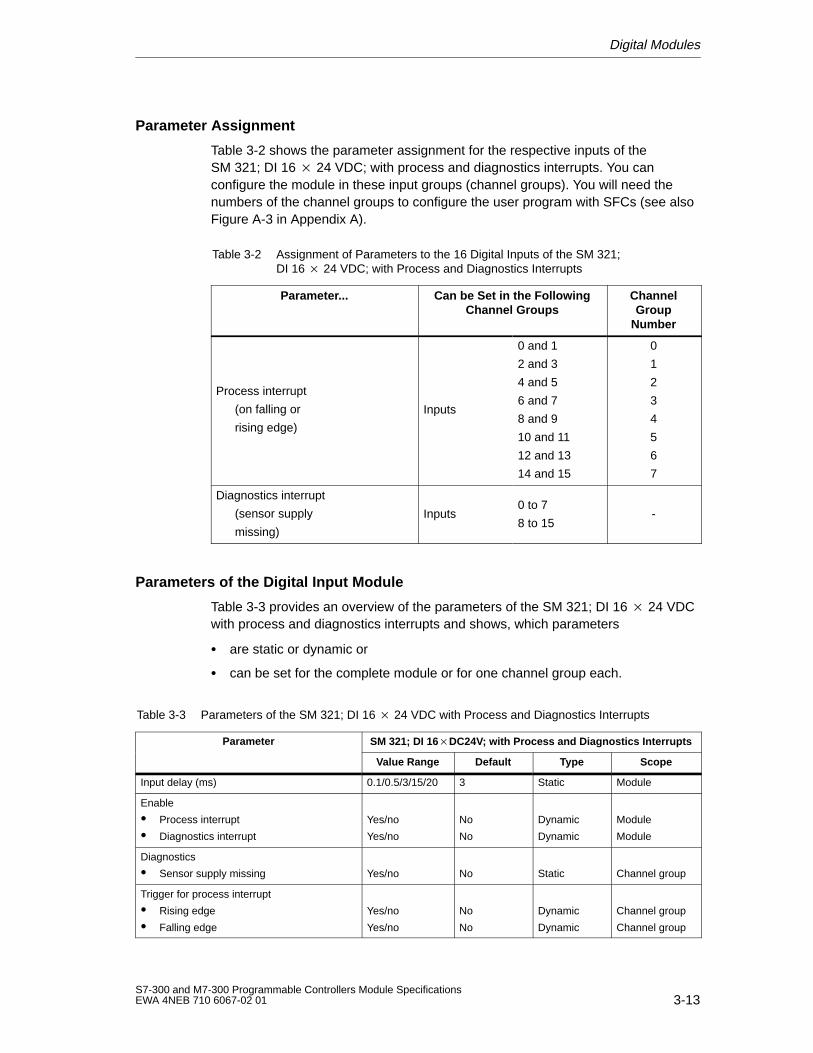
Digital Modules
3-13S7-300 and M7-300 Programmable Controllers Module SpecificationsEWA 4NEB 710 6067-02 01
Parameter Assignment
Table 3-2 shows the parameter assignment for the respective inputs of theSM 321; DI 16 24 VDC; with process and diagnostics interrupts. You canconfigure the module in these input groups (channel groups). You will need thenumbers of the channel groups to configure the user program with SFCs (see alsoFigure A-3 in Appendix A).
Table 3-2 Assignment of Parameters to the 16 Digital Inputs of the SM 321;DI 16 24 VDC; with Process and Diagnostics Interrupts
Parameter... Can be Set in the FollowingChannel Groups
ChannelGroup
Number
Process interrupt
(on falling or
rising edge)
Inputs
0 and 1
2 and 3
4 and 5
6 and 7
8 and 9
10 and 11
12 and 13
14 and 15
0
1
2
3
4
5
6
7
Diagnostics interrupt
(sensor supply
missing)
Inputs0 to 7
8 to 15-
Parameters of the Digital Input Module
Table 3-3 provides an overview of the parameters of the SM 321; DI 16 24 VDCwith process and diagnostics interrupts and shows, which parameters
are static or dynamic or
can be set for the complete module or for one channel group each.
Table 3-3 Parameters of the SM 321; DI 16 24 VDC with Process and Diagnostics Interrupts
Parameter SM 321; DI 16DC24V; with Process and Diagnostics Interrupts
Value Range Default Type Scope
Input delay (ms) 0.1/0.5/3/15/20 3 Static Module
Enable
Process interrupt
Diagnostics interrupt
Yes/no
Yes/no
No
No
Dynamic
Dynamic
Module
Module
Diagnostics
Sensor supply missing Yes/no No Static Channel group
Trigger for process interrupt
Rising edge
Falling edge
Yes/no
Yes/no
No
No
Dynamic
Dynamic
Channel group
Channel group
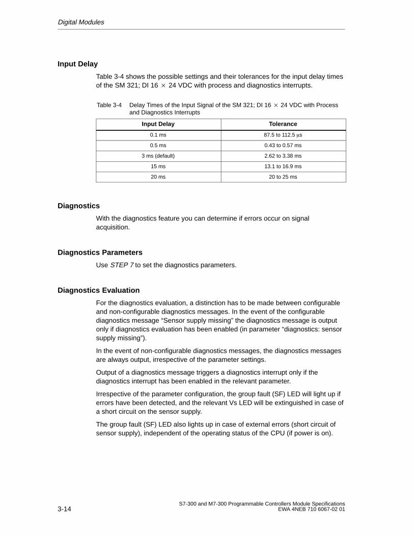
Digital Modules
3-14S7-300 and M7-300 Programmable Controllers Module Specifications
EWA 4NEB 710 6067-02 01
Input Delay
Table 3-4 shows the possible settings and their tolerances for the input delay timesof the SM 321; DI 16 24 VDC with process and diagnostics interrupts.
Table 3-4 Delay Times of the Input Signal of the SM 321; DI 16 24 VDC with Processand Diagnostics Interrupts
Input Delay Tolerance
0.1 ms 87.5 to 112.5 s
0.5 ms 0.43 to 0.57 ms
3 ms (default) 2.62 to 3.38 ms
15 ms 13.1 to 16.9 ms
20 ms 20 to 25 ms
Diagnostics
With the diagnostics feature you can determine if errors occur on signalacquisition.
Diagnostics Parameters
Use STEP 7 to set the diagnostics parameters.
Diagnostics Evaluation
For the diagnostics evaluation, a distinction has to be made between configurableand non-configurable diagnostics messages. In the event of the configurablediagnostics message “Sensor supply missing” the diagnostics message is outputonly if diagnostics evaluation has been enabled (in parameter “diagnostics: sensorsupply missing”).
In the event of non-configurable diagnostics messages, the diagnostics messagesare always output, irrespective of the parameter settings.
Output of a diagnostics message triggers a diagnostics interrupt only if thediagnostics interrupt has been enabled in the relevant parameter.
Irrespective of the parameter configuration, the group fault (SF) LED will light up iferrors have been detected, and the relevant Vs LED will be extinguished in case ofa short circuit on the sensor supply.
The group fault (SF) LED also lights up in case of external errors (short circuit ofsensor supply), independent of the operating status of the CPU (if power is on).
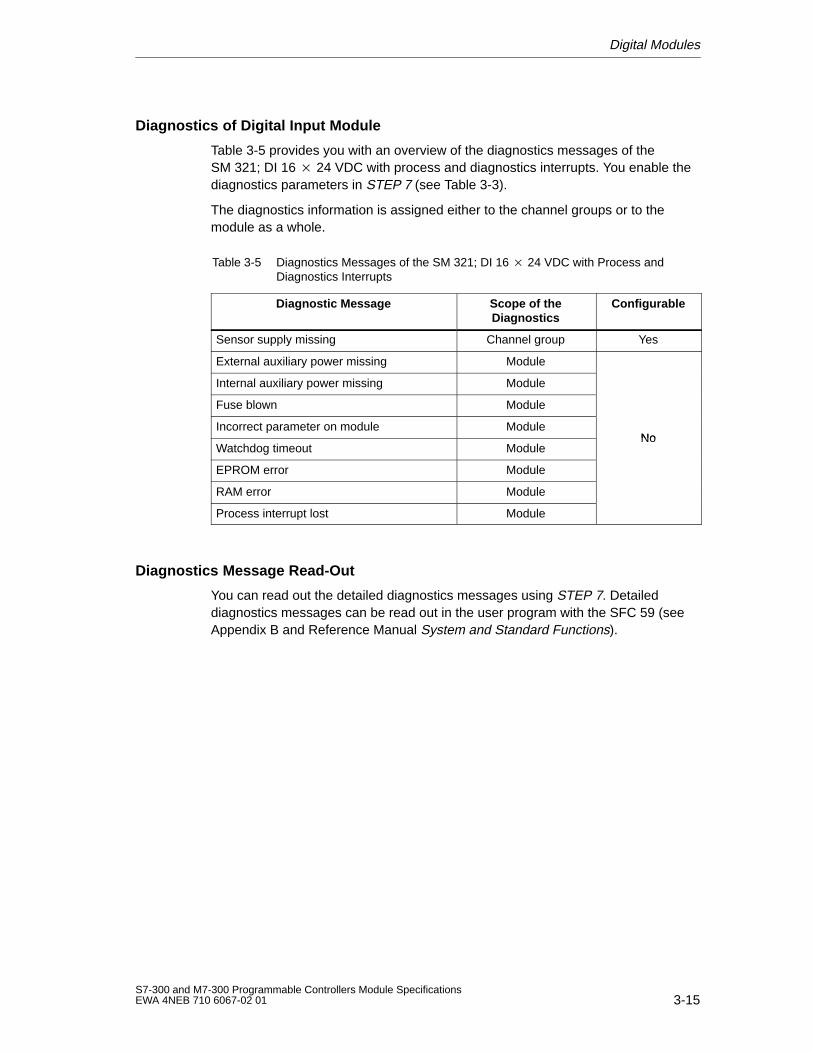
Digital Modules
3-15S7-300 and M7-300 Programmable Controllers Module SpecificationsEWA 4NEB 710 6067-02 01
Diagnostics of Digital Input Module
Table 3-5 provides you with an overview of the diagnostics messages of theSM 321; DI 16 24 VDC with process and diagnostics interrupts. You enable thediagnostics parameters in STEP 7 (see Table 3-3).
The diagnostics information is assigned either to the channel groups or to themodule as a whole.
Table 3-5 Diagnostics Messages of the SM 321; DI 16 24 VDC with Process andDiagnostics Interrupts
Diagnostic Message Scope of theDiagnostics
Configurable
Sensor supply missing Channel group Yes
External auxiliary power missing Module
Internal auxiliary power missing Module
Fuse blown Module
Incorrect parameter on module ModuleNo
Watchdog timeout ModuleNo
EPROM error Module
RAM error Module
Process interrupt lost Module
Diagnostics Message Read-Out
You can read out the detailed diagnostics messages using STEP 7. Detaileddiagnostics messages can be read out in the user program with the SFC 59 (seeAppendix B and Reference Manual System and Standard Functions).
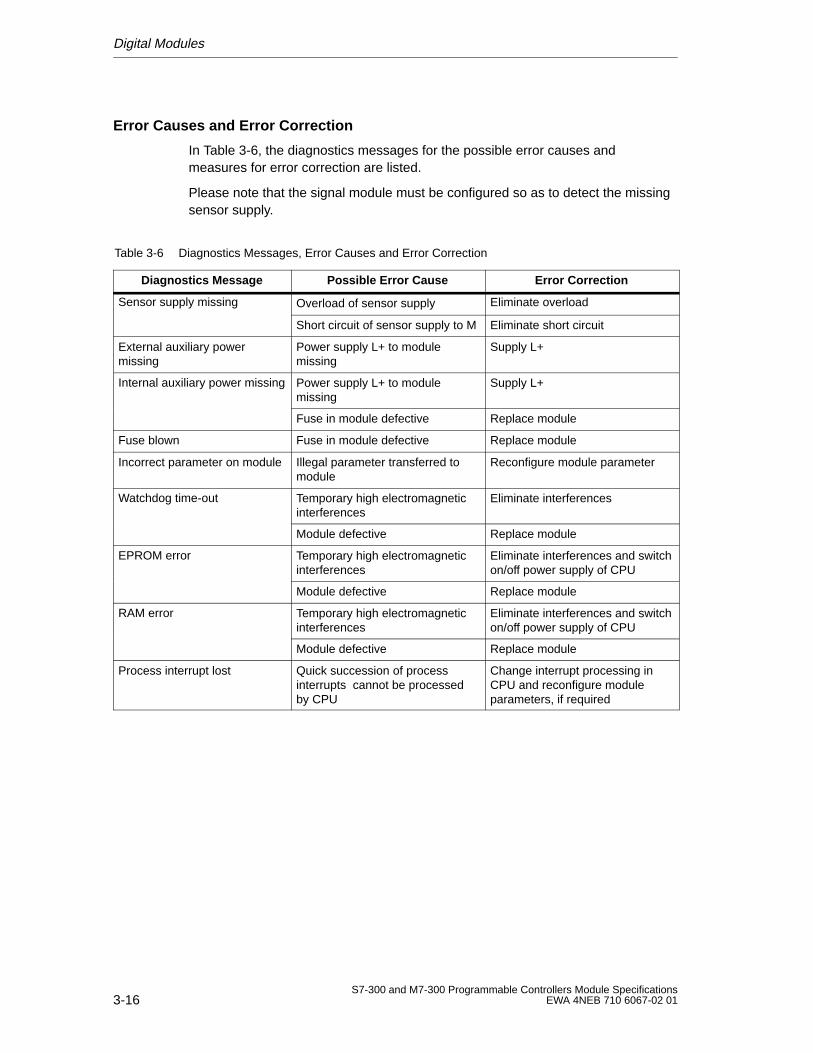
Digital Modules
3-16S7-300 and M7-300 Programmable Controllers Module Specifications
EWA 4NEB 710 6067-02 01
Error Causes and Error Correction
In Table 3-6, the diagnostics messages for the possible error causes andmeasures for error correction are listed.
Please note that the signal module must be configured so as to detect the missingsensor supply.
Table 3-6 Diagnostics Messages, Error Causes and Error Correction
Diagnostics Message Possible Error Cause Error Correction
Sensor supply missing Overload of sensor supply Eliminate overload
Short circuit of sensor supply to M Eliminate short circuit
External auxiliary powermissing
Power supply L+ to modulemissing
Supply L+
Internal auxiliary power missing Power supply L+ to modulemissing
Supply L+
Fuse in module defective Replace module
Fuse blown Fuse in module defective Replace module
Incorrect parameter on module Illegal parameter transferred tomodule
Reconfigure module parameter
Watchdog time-out Temporary high electromagneticinterferences
Eliminate interferences
Module defective Replace module
EPROM error Temporary high electromagneticinterferences
Eliminate interferences and switchon/off power supply of CPU
Module defective Replace module
RAM error Temporary high electromagneticinterferences
Eliminate interferences and switchon/off power supply of CPU
Module defective Replace module
Process interrupt lost Quick succession of processinterrupts cannot be processedby CPU
Change interrupt processing inCPU and reconfigure moduleparameters, if required
Digital Modules
3-17S7-300 and M7-300 Programmable Controllers Module SpecificationsEWA 4NEB 710 6067-02 01
Interrupts
The following interrupts exist with the SM 321; DI 16 24VDC with process anddiagnostics interrupts:
Diagnostics interrupt
Process interrupt.
Configuring Interrupts
Use STEP 7 to configure the interrupts.
Default Setting
The default setting for interrupts is disabled.
Diagnostics Interrupt
If an error (for example, sensor supply missing) is detected or remedied, themodule triggers a diagnostics interrupt, provided the diagnostics interrupt isenabled. The CPU interrupts the execution of the user program or of priorityclasses with low priority and processes the diagnostics interrupt block (OB 82).
Process Interrupt
Depending on the configuration, the module can trigger for each channel group aprocess interrupt, either in case of rising, falling or both edges of a signal statechange. In the user program, you can use SFCs to find out which one of the twochannels of a channel group has triggered the interrupt (see Reference ManualSystem and Standard Functions).
Pending process interrupts trigger process interrupt processing in the CPU(OB 40). The CPU interrupts the execution of the user program or of the priorityclasses with low priority. The signal module can buffer one interrupt per channel. Ifno priority classes with higher priority are to be processed, the buffered interrupts(of all modules) are processed in the sequence in which they have occurred.
Process Interrupt Lost
In an interrupt has been buffered for a channel and another interrupt occurs on thatchannel before it has been processed by the CPU, a diagnostics interrupt “processinterrupt lost” is triggered.
More interrupts on this channel are not acquired until processing of the interruptbuffered on this channel has been executed.
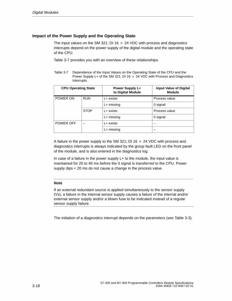
Digital Modules
3-18S7-300 and M7-300 Programmable Controllers Module Specifications
EWA 4NEB 710 6067-02 01
Impact of the Power Supply and the Operating State
The input values on the SM 321; DI 16 24 VDC with process and diagnosticsinterrupts depend on the power supply of the digital module and the operating stateof the CPU.
Table 3-7 provides you with an overview of these relationships.
Table 3-7 Dependence of the Input Values on the Operating State of the CPU and thePower Supply L+ of the SM 321; DI 16 24 VDC with Process and DiagnosticsInterrupts
CPU Operating State Power Supply L+to Digital Module
Input V alue of DigitalModule
POWER ON RUN L+ exists Process value
L+ missing 0 signal
STOP L+ exists Process value
L+ missing 0 signal
POWER OFF – L+ exists –
L+ missing –
A failure in the power supply to the SM 321; DI 16 24 VDC with process anddiagnostics interrupts is always indicated by the group fault LED on the front panelof the module, and is also entered in the diagnostics log.
In case of a failure in the power supply L+ to the module, the input value ismaintained for 20 to 40 ms before the 0 signal is transferred to the CPU. Powersupply dips < 20 ms do not cause a change in the process value.
Note
If an external redundant source is applied simultaneously to the sensor supply(Vs), a failure in the internal sensor supply causes a failure of the internal and/orexternal sensor supply and/or a blown fuse to be indicated instead of a regularsensor supply failure.
The initiation of a diagnostics interrupt depends on the parameters (see Table 3-3).
Digital Modules
3-19S7-300 and M7-300 Programmable Controllers Module SpecificationsEWA 4NEB 710 6067-02 01
3.1.4 Digital Input Module SM 321; DI 16 24 VDC (Source Input)
Order Number
6ES7 321-1BH5-AA0
Characteristics
The SM 321; DI 16 24 VDC (source input) has the following salient features:
16 input points, source input, isolated in groups of 16
24 VDC rated input voltage
Suitable for switches and 2/3/4-wire proximity switches (BEROs)
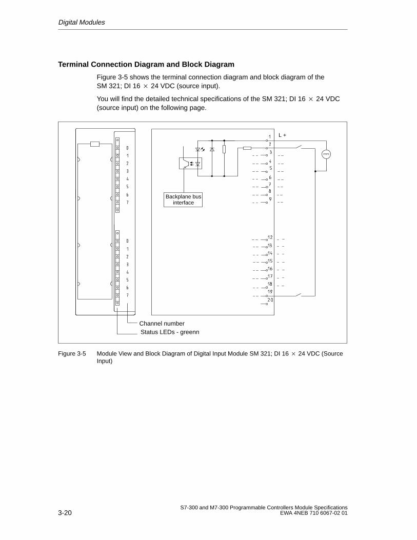
Digital Modules
3-20S7-300 and M7-300 Programmable Controllers Module Specifications
EWA 4NEB 710 6067-02 01
Terminal Connection Diagram and Block Diagram
Figure 3-5 shows the terminal connection diagram and block diagram of theSM 321; DI 16 24 VDC (source input).
You will find the detailed technical specifications of the SM 321; DI 16 24 VDC(source input) on the following page.
Channel numberStatus LEDs - greenn
Backplane businterface
L +
Figure 3-5 Module View and Block Diagram of Digital Input Module SM 321; DI 16 24 VDC (SourceInput)
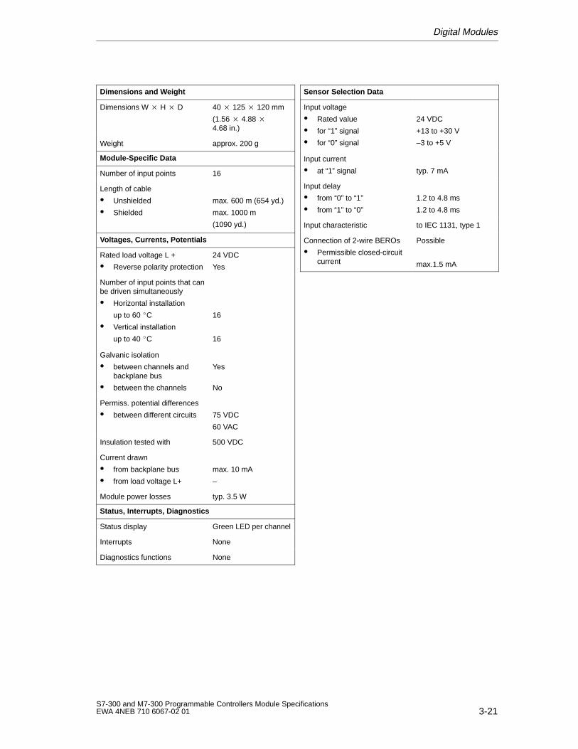
Digital Modules
3-21S7-300 and M7-300 Programmable Controllers Module SpecificationsEWA 4NEB 710 6067-02 01
Dimensions and W eight
Dimensions W H D 40 125 120 mm
(1.56 4.88 4.68 in.)
Weight approx. 200 g
Module-Specific Data
Number of input points 16
Length of cable
Unshielded
Shielded
max. 600 m (654 yd.)
max. 1000 m
(1090 yd.)
Voltages, Currents, Potentials
Rated load voltage L +
Reverse polarity protection
24 VDC
Yes
Number of input points that canbe driven simultaneously
Horizontal installation
up to 60 C
Vertical installation
up to 40 C
16
16
Galvanic isolation
between channels andbackplane bus
between the channels
Yes
No
Permiss. potential differences
between different circuits 75 VDC
60 VAC
Insulation tested with 500 VDC
Current drawn
from backplane bus
from load voltage L+
max. 10 mA
–
Module power losses typ. 3.5 W
Status, Interrupts, Diagnostics
Status display Green LED per channel
Interrupts None
Diagnostics functions None
Sensor Selection Data
Input voltage
Rated value
for “1” signal
for “0” signal
24 VDC
+13 to +30 V
–3 to +5 V
Input current
at “1” signal typ. 7 mA
Input delay
from “0” to “1”
from “1” to “0”
1.2 to 4.8 ms
1.2 to 4.8 ms
Input characteristic to IEC 1131, type 1
Connection of 2-wire BEROs
Permissible closed-circuitcurrent
Possible
max.1.5 mA
Digital Modules
3-22S7-300 and M7-300 Programmable Controllers Module Specifications
EWA 4NEB 710 6067-02 01
3.1.5 Digital Input Module SM 321; DI 16 120 VAC
Order No.
6ES7 321-1EH01-0AA0
Characteristics
The digital input module SM 321; DI 16 120 VAC has the following salientfeatures:
16 input points, isolated in groups of 4
120 VAC rated input voltage
Suitable for switches and 2/3/-wire AC proximity switches
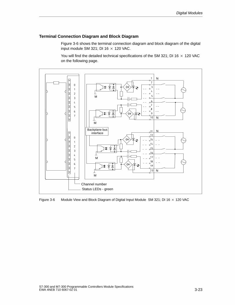
Digital Modules
3-23S7-300 and M7-300 Programmable Controllers Module SpecificationsEWA 4NEB 710 6067-02 01
Terminal Connection Diagram and Block Diagram
Figure 3-6 shows the terminal connection diagram and block diagram of the digitalinput module SM 321; DI 16 120 VAC.
You will find the detailed technical specifications of the SM 321; DI 16 120 VACon the following page.
Channel numberStatus LEDs - green
M
N
N
N
M
M
M
Backplane businterface
N
Figure 3-6 Module View and Block Diagram of Digital Input Module SM 321; DI 16 120 VAC
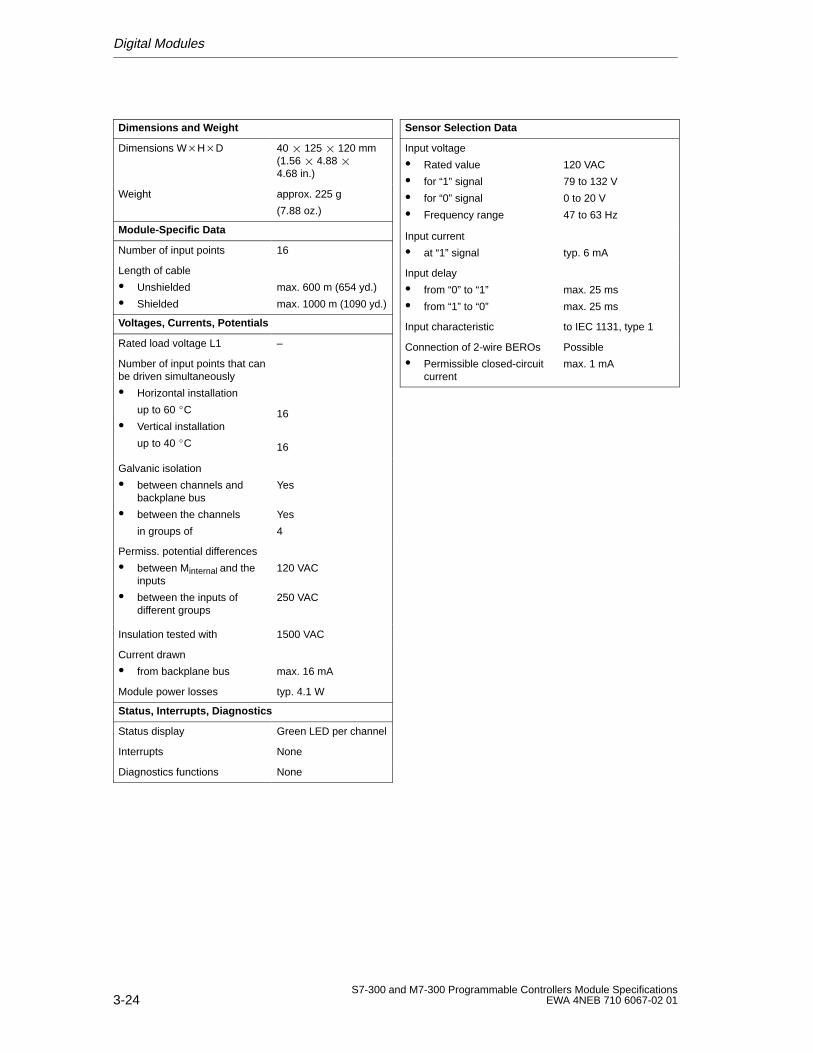
Digital Modules
3-24S7-300 and M7-300 Programmable Controllers Module Specifications
EWA 4NEB 710 6067-02 01
Dimensions and W eight
Dimensions WHD 40 125 120 mm(1.56 4.88 4.68 in.)
Weight approx. 225 g
(7.88 oz.)
Module-Specific Data
Number of input points 16
Length of cable
Unshielded
Shielded
max. 600 m (654 yd.)
max. 1000 m (1090 yd.)
Voltages, Currents, Potentials
Rated load voltage L1 –
Number of input points that canbe driven simultaneously
Horizontal installation
up to 60 C
Vertical installation
up to 40 C
16
16
Galvanic isolation
between channels andbackplane bus
between the channels
in groups of
Yes
Yes
4
Permiss. potential differences
between Minternal and theinputs
between the inputs ofdifferent groups
120 VAC
250 VAC
Insulation tested with 1500 VAC
Current drawn
from backplane bus max. 16 mA
Module power losses typ. 4.1 W
Status, Interrupts, Diagnostics
Status display Green LED per channel
Interrupts None
Diagnostics functions None
Sensor Selection Data
Input voltage
Rated value
for “1” signal
for “0” signal
Frequency range
120 VAC
79 to 132 V
0 to 20 V
47 to 63 Hz
Input current
at “1” signal typ. 6 mA
Input delay
from “0” to “1”
from “1” to “0”
max. 25 ms
max. 25 ms
Input characteristic to IEC 1131, type 1
Connection of 2-wire BEROs
Permissible closed-circuitcurrent
Possible
max. 1 mA
Digital Modules
3-25S7-300 and M7-300 Programmable Controllers Module SpecificationsEWA 4NEB 710 6067-02 01
3.1.6 Digital Input Module SM 321; DI 8 120/230 VAC
Order No.
6ES7 321-1FF01-0AA0
Characteristics
The digital input module SM 321; DI 8 120/230 VAC has the following salientfeatures:
8 input points, isolated in groups of 2
120/230 VAC rated input voltage
Suitable for switches and 2/3/-wire AC proximity switches
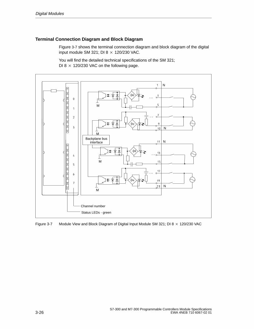
Digital Modules
3-26S7-300 and M7-300 Programmable Controllers Module Specifications
EWA 4NEB 710 6067-02 01
Terminal Connection Diagram and Block Diagram
Figure 3-7 shows the terminal connection diagram and block diagram of the digitalinput module SM 321; DI 8 120/230 VAC.
You will find the detailed technical specifications of the SM 321;DI 8 120/230 VAC on the following page.
Channel number
Status LEDs - green
M
N
N
M
M
N
NM
Backplane businterface
Figure 3-7 Module View and Block Diagram of Digital Input Module SM 321; DI 8 120/230 VAC
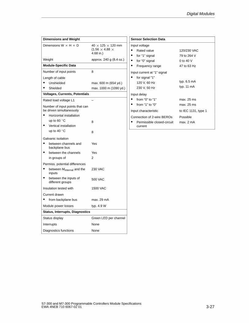
Digital Modules
3-27S7-300 and M7-300 Programmable Controllers Module SpecificationsEWA 4NEB 710 6067-02 01
Dimensions and W eight
Dimensions W H D 40 125 120 mm(1.56 4.88 4.68 in.)
Weight approx. 240 g (8.4 oz.)
Module-Specific Data
Number of input points 8
Length of cable
Unshielded
Shielded
max. 600 m (654 yd.)
max. 1000 m (1090 yd.)
Voltages, Currents, Potentials
Rated load voltage L1 –
Number of input points that canbe driven simultaneously
Horizontal installation
up to 60 C
Vertical installation
up to 40 C
8
8
Galvanic isolation
between channels andbackplane bus
between the channels
in groups of
Yes
Yes
2
Permiss. potential differences
between Minternal and theinputs
between the inputs ofdifferent groups
230 VAC
500 VAC
Insulation tested with 1500 VAC
Current drawn
from backplane bus max. 29 mA
Module power losses typ. 4.9 W
Status, Interrupts, Diagnostics
Status display Green LED per channel
Interrupts None
Diagnostics functions None
Sensor Selection Data
Input voltage
Rated value
for “1” signal
for “0” signal
Frequency range
120/230 VAC
79 to 264 V
0 to 40 V
47 to 63 Hz
Input current at “1” signal
for signal ”1”
120 V, 60 Hz
230 V, 50 Hz
typ. 6.5 mA
typ. 11 mA
Input delay
from “0” to “1”
from “1” to “0”
max. 25 ms
max. 25 ms
Input characteristic to IEC 1131, type 1
Connection of 2-wire BEROs
Permissible closed-circuitcurrent
Possible
max. 2 mA

Digital Modules
3-28S7-300 and M7-300 Programmable Controllers Module Specifications
EWA 4NEB 710 6067-02 01
3.1.7 Digital Input Module SM 321; DI 32 120 VAC
Order No.
6ES7 321-1EL00-0AA0
Characteristics
The digital input module, SM 321; DI 32 120 VAC, has the following salientfeatures:
32 input points, isolated in groups of 8
120 VAC rated input voltage
Suitable for switches and 2/3-wire AC proximity switches
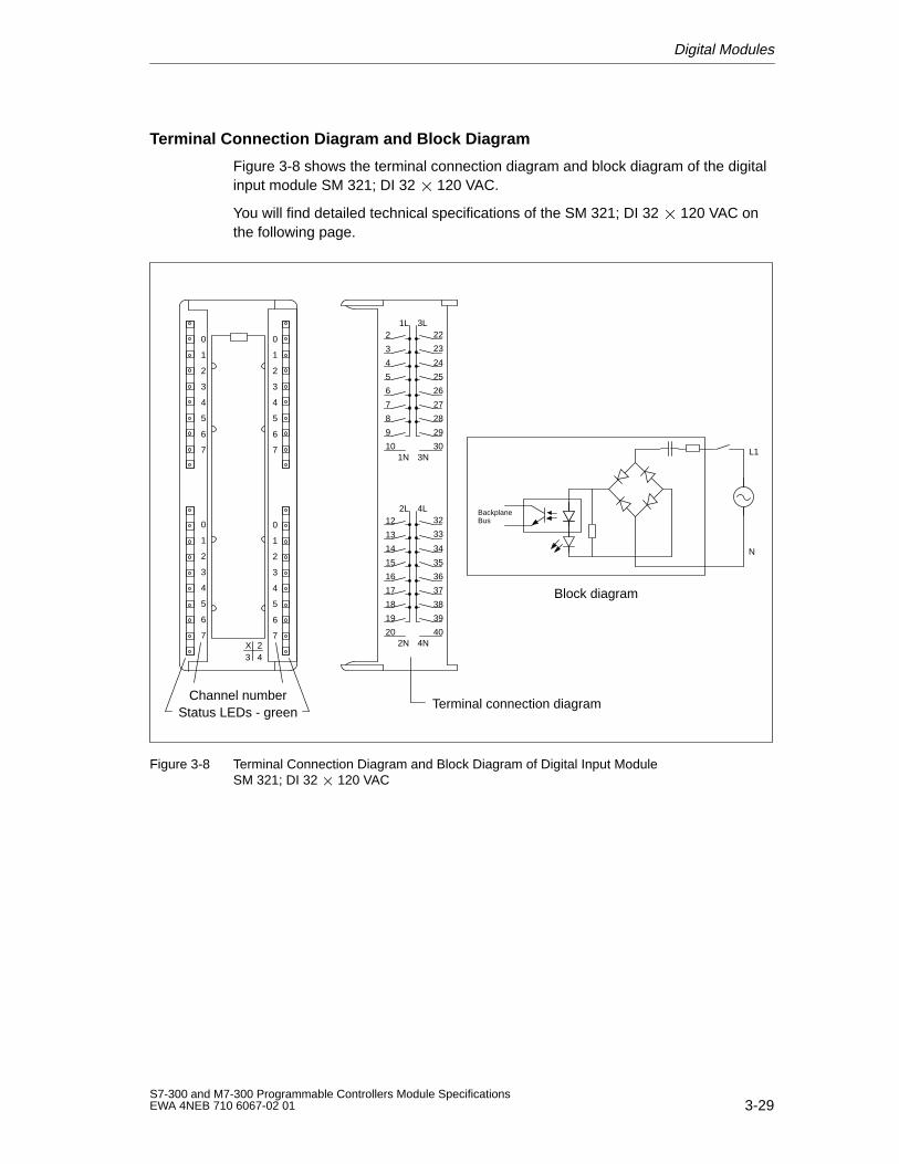
Digital Modules
3-29S7-300 and M7-300 Programmable Controllers Module SpecificationsEWA 4NEB 710 6067-02 01
Terminal Connection Diagram and Block Diagram
Figure 3-8 shows the terminal connection diagram and block diagram of the digitalinput module SM 321; DI 32 120 VAC.
You will find detailed technical specifications of the SM 321; DI 32 120 VAC onthe following page.
0
1
2
3
4
5
6
7
2
3
4
5
6
7
8
9
10
1L
1N
24
X3
0
1
2
3
4
5
6
7
0
1
2
3
4
5
6
7
24
25
26
27
28
29
30
3L
3N
12
13
14
15
16
17
18
19
20
2L
2N
34
35
36
37
38
39
40
4L
4N
32
33
22
23
BackplaneBus
N
L1
0
1
2
3
4
5
6
7
Block diagram
Channel numberStatus LEDs - green
Terminal connection diagram
Figure 3-8 Terminal Connection Diagram and Block Diagram of Digital Input ModuleSM 321; DI 32 120 VAC
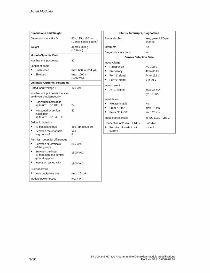
Digital Modules
3-30S7-300 and M7-300 Programmable Controllers Module Specifications
EWA 4NEB 710 6067-02 01
Dimensions and W eight
Dimensions WHD 40125120 mm(1.564.884.68 in.)
Weight approx. 300 g (10.6 oz.)
Module-Specific Data
Number of input points 32
Length of cable
Unshielded
Shielded
max. 600 m (654 yd.)
max. 1000 m (1090 yd.)
Voltages, Currents, Potentials
Rated input voltage L1 120 VAC
Number of input points that canbe driven simultaneously
Horizontal installation up to 60 C/140 F 24
Horizontal or verticalinstallation up to 40 C/104 F
32
Galvanic isolation
To backplane bus
Between the channels in groups of
Yes (optocoupler)
Yes8
Permiss. potential differences
Between N terminals of the groups
Between the input (N terminal) and centralgrounding point
Insulation tested with
250 VAC
1500 VAC
1500 VAC
Current drawn
from backplane bus max. 16 mA
Module power losses typ. 4 W
Status, Interrupts, Diagnostics
Status display Yes; green LED perchannel
Interrupts No
Diagnostics functions No
Sensor Selection Data
Input voltage
Rated value
Frequency
For ‘‘1’’ signal
For ‘‘0’’ signal
AC 120 V
47 to 63 Hz
74 to 132 V
0 to 20 V
Input current
At ‘‘1’’ signal max. 27 mA
typ. 21 mA
Input delay
Programmable
From ‘‘0’’ to ‘‘1’’
From ‘‘1’’ to ‘‘0’’
No
max. 15 ms
max. 25 ms
Input characteristic to IEC 1131, Type 2
Connection of 2-wire BEROs
Permiss. closed-circuitcurrent
Possible
< 4 mA
Digital Modules
3-31S7-300 and M7-300 Programmable Controllers Module SpecificationsEWA 4NEB 710 6067-02 01
3.2 Digital Output Modules
List of Digital Output Modules
The following digital output modules are described in this chapter:
SM 322; DO 32 24 VDC/0.5 A
SM 322; DO 16 24 VDC/0.5 A
SM 322; DO 8 24 VDC/0.5 A with diagnostics interrupt
SM 322; DO 8 24 VDC/2 A
SM 322; DO 16 120 VAC/1 A
SM 322; DO 8 120/230 VAC/2 A
SM 322; DO 32 120 VAC/1.0 A
3.2.1 Digital Output Module SM 322; DO 32 24 VDC/0.5 A
Order No.
6ES7 322-1BL00-0AA0
Characteristics
The digital output module SM 322; DO 32 24 VDC/0.5 A has the followingsalient features:
32 output points, isolated in groups of 8
0.5 A output current
24 VDC rated load voltage
Suitable for solenoid valves, DC contactors and indicator lights
Special Feature
When the power supply is switched on via a mechanical contact, the digital outputmodule SM 322; SO 32 24 VDC/0.5 A sends a “1” signal to its outputs forapproximately 50 s. You must observe this when using the digital output moduleSM 322; DO 32 24 VDC/0.5 A for high-speed counters.
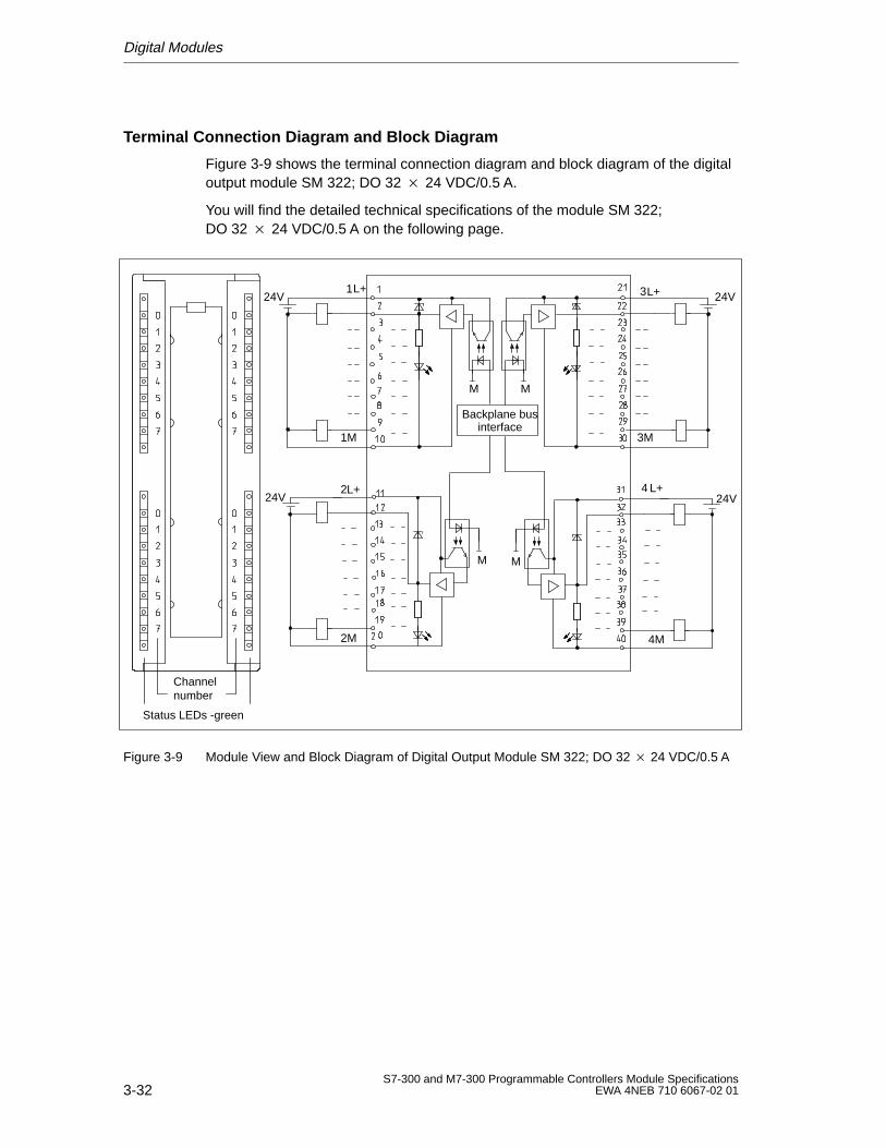
Digital Modules
3-32S7-300 and M7-300 Programmable Controllers Module Specifications
EWA 4NEB 710 6067-02 01
Terminal Connection Diagram and Block Diagram
Figure 3-9 shows the terminal connection diagram and block diagram of the digitaloutput module SM 322; DO 32 24 VDC/0.5 A.
You will find the detailed technical specifications of the module SM 322;DO 32 24 VDC/0.5 A on the following page.
Channelnumber
Status LEDs -green
Backplane businterface
L+
L+
L+
L+
1
2
3
4
M M
M M
1M
2M
3M
4M
24V
24V
24V
24V
Figure 3-9 Module View and Block Diagram of Digital Output Module SM 322; DO 32 24 VDC/0.5 A
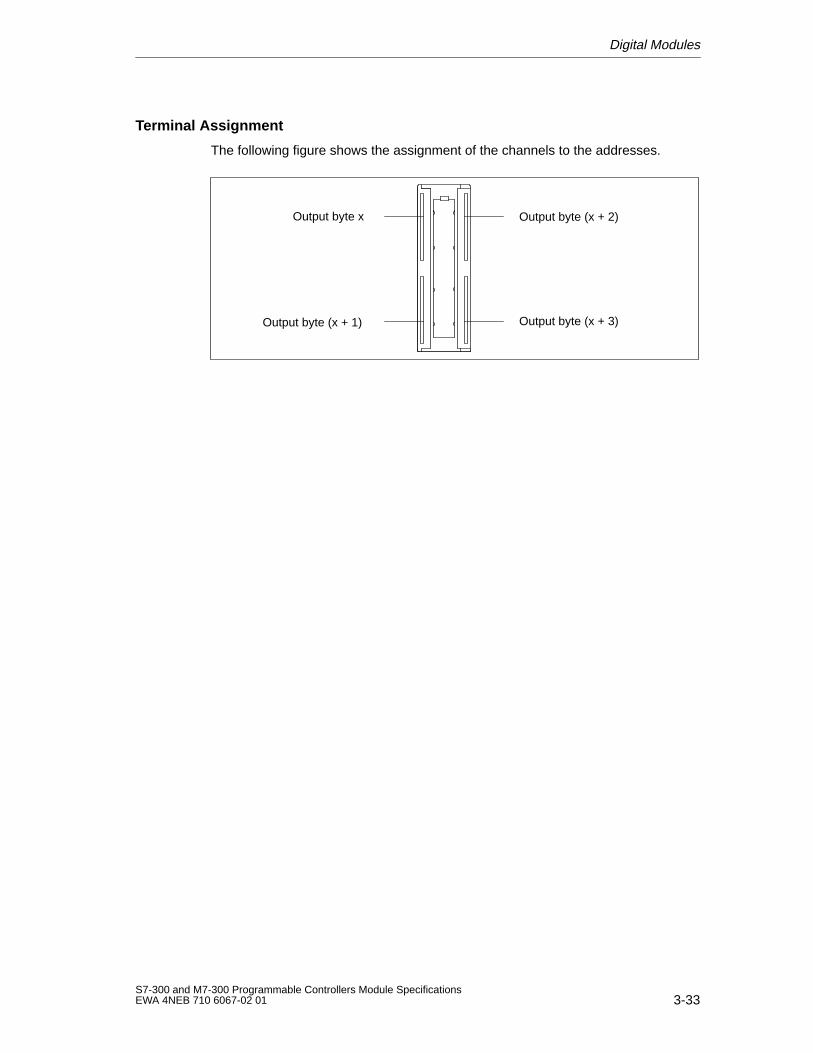
Digital Modules
3-33S7-300 and M7-300 Programmable Controllers Module SpecificationsEWA 4NEB 710 6067-02 01
Terminal Assignment
The following figure shows the assignment of the channels to the addresses.
Output byte x
Output byte (x + 1)
Output byte (x + 2)
Output byte (x + 3)
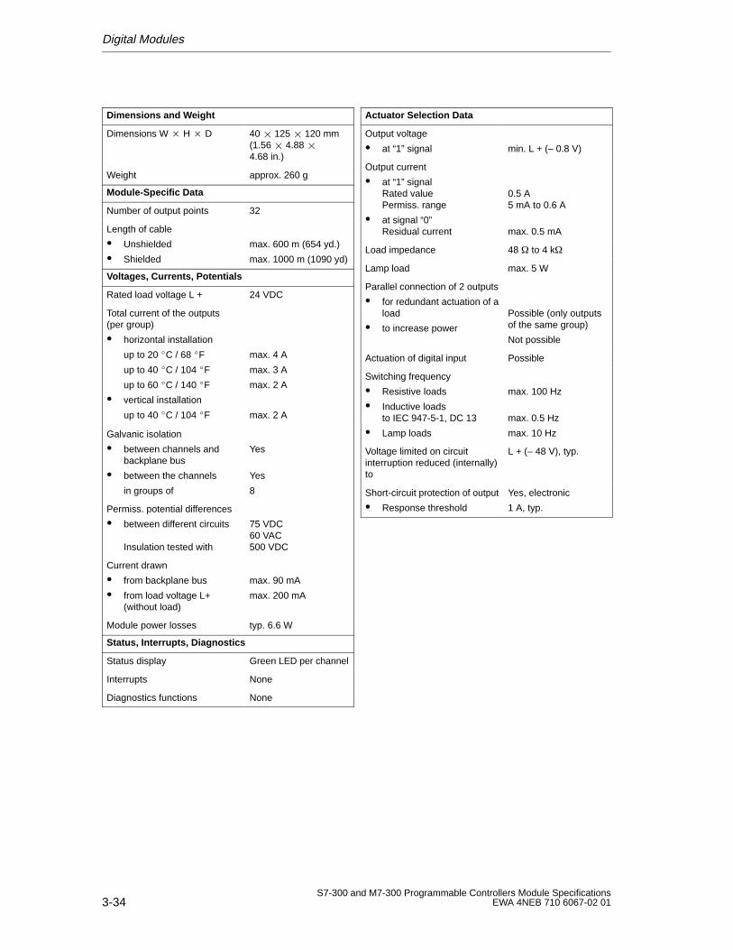
Digital Modules
3-34S7-300 and M7-300 Programmable Controllers Module Specifications
EWA 4NEB 710 6067-02 01
Dimensions and W eight
Dimensions W H D 40 125 120 mm(1.56 4.88 4.68 in.)
Weight approx. 260 g
Module-Specific Data
Number of output points 32
Length of cable
Unshielded
Shielded
max. 600 m (654 yd.)
max. 1000 m (1090 yd)
Voltages, Currents, Potentials
Rated load voltage L + 24 VDC
Total current of the outputs(per group)
horizontal installation
up to 20 C / 68 F
up to 40 C / 104 F
up to 60 C / 140 F
vertical installation
up to 40 C / 104 F
max. 4 A
max. 3 A
max. 2 A
max. 2 A
Galvanic isolation
between channels andbackplane bus
between the channels
in groups of
Yes
Yes
8
Permiss. potential differences
between different circuits
Insulation tested with
75 VDC60 VAC500 VDC
Current drawn
from backplane bus
from load voltage L+(without load)
max. 90 mA
max. 200 mA
Module power losses typ. 6.6 W
Status, Interrupts, Diagnostics
Status display Green LED per channel
Interrupts None
Diagnostics functions None
Actuator Selection Data
Output voltage
at “1” signal min. L + (– 0.8 V)
Output current
at “1” signalRated valuePermiss. range
at signal “0”Residual current
0.5 A5 mA to 0.6 A
max. 0.5 mA
Load impedance 48 to 4 k
Lamp load max. 5 W
Parallel connection of 2 outputs
for redundant actuation of aload
to increase power
Possible (only outputsof the same group)
Not possible
Actuation of digital input Possible
Switching frequency
Resistive loads
Inductive loadsto IEC 947-5-1, DC 13
Lamp loads
max. 100 Hz
max. 0.5 Hz
max. 10 Hz
Voltage limited on circuitinterruption reduced (internally)to
L + (– 48 V), typ.
Short-circuit protection of output
Response threshold
Yes, electronic
1 A, typ.
Digital Modules
3-35S7-300 and M7-300 Programmable Controllers Module SpecificationsEWA 4NEB 710 6067-02 01
3.2.2 Digital Output Module SM 322; DO 16 24 VDC/0.5 A
Order No.
6ES7 322-1BH01-0AA0
Characteristics
The digital output module SM 322; DO 16 24 VDC/0.5 A has the followingsalient features:
16 output points, isolated in groups of 8
0.5 A output current
24 VDC rated load voltage
Suitable for solenoid valves, DC contactors and indicator signals.
Special Feature
When the 24 V power supply is switched on via a mechanical contact, the digitaloutput module SM 322; DO 16 24 VDC/0.5 A sends a “1” signal to its outputsfor approximately 50 s. You must observe this when using the digital outputmodule SM 322; DO 16 24 VDC/0.5 A for high-speed counters!
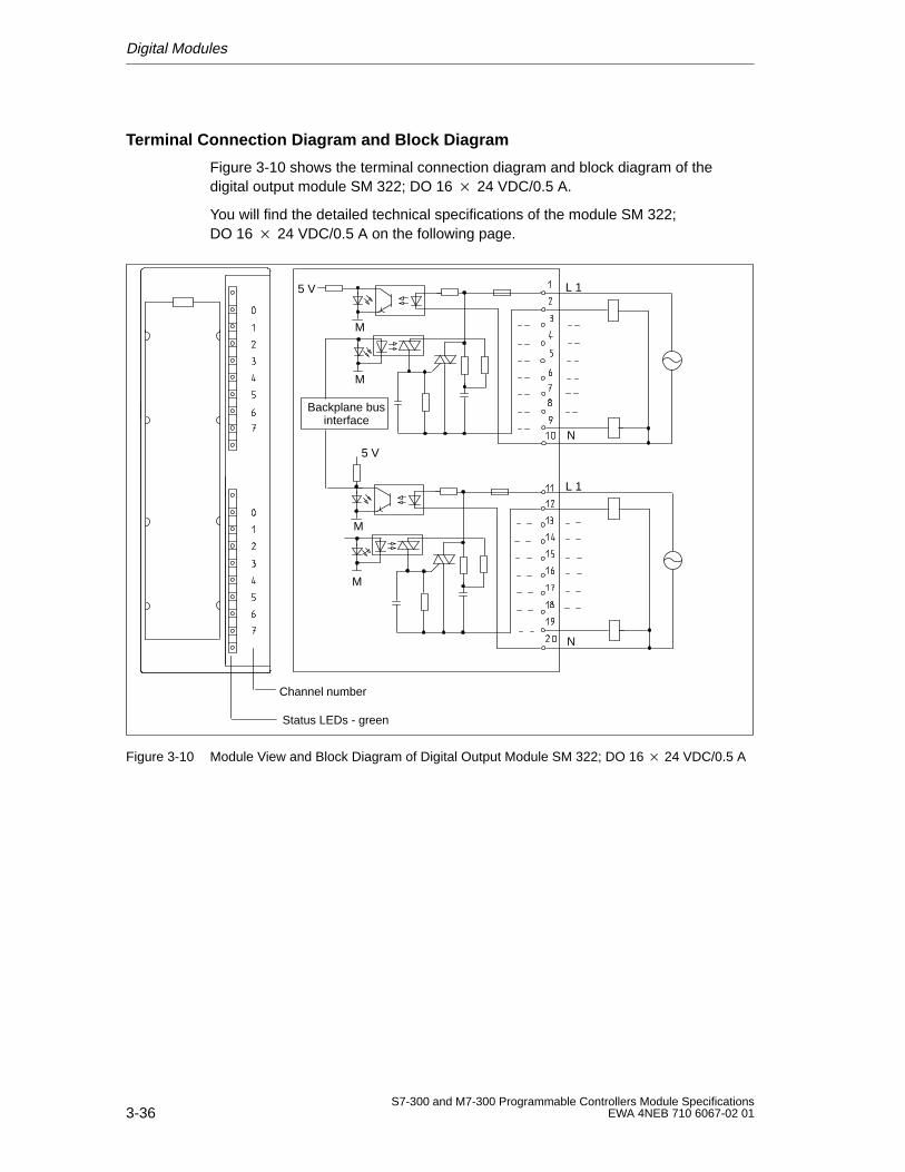
Digital Modules
3-36S7-300 and M7-300 Programmable Controllers Module Specifications
EWA 4NEB 710 6067-02 01
Terminal Connection Diagram and Block Diagram
Figure 3-10 shows the terminal connection diagram and block diagram of thedigital output module SM 322; DO 16 24 VDC/0.5 A.
You will find the detailed technical specifications of the module SM 322;DO 16 24 VDC/0.5 A on the following page.
Channel number
Status LEDs - green
Backplane businterface
5 V
5 V
N
L 1
L 1
N
M
M
M
M
Figure 3-10 Module View and Block Diagram of Digital Output Module SM 322; DO 16 24 VDC/0.5 A
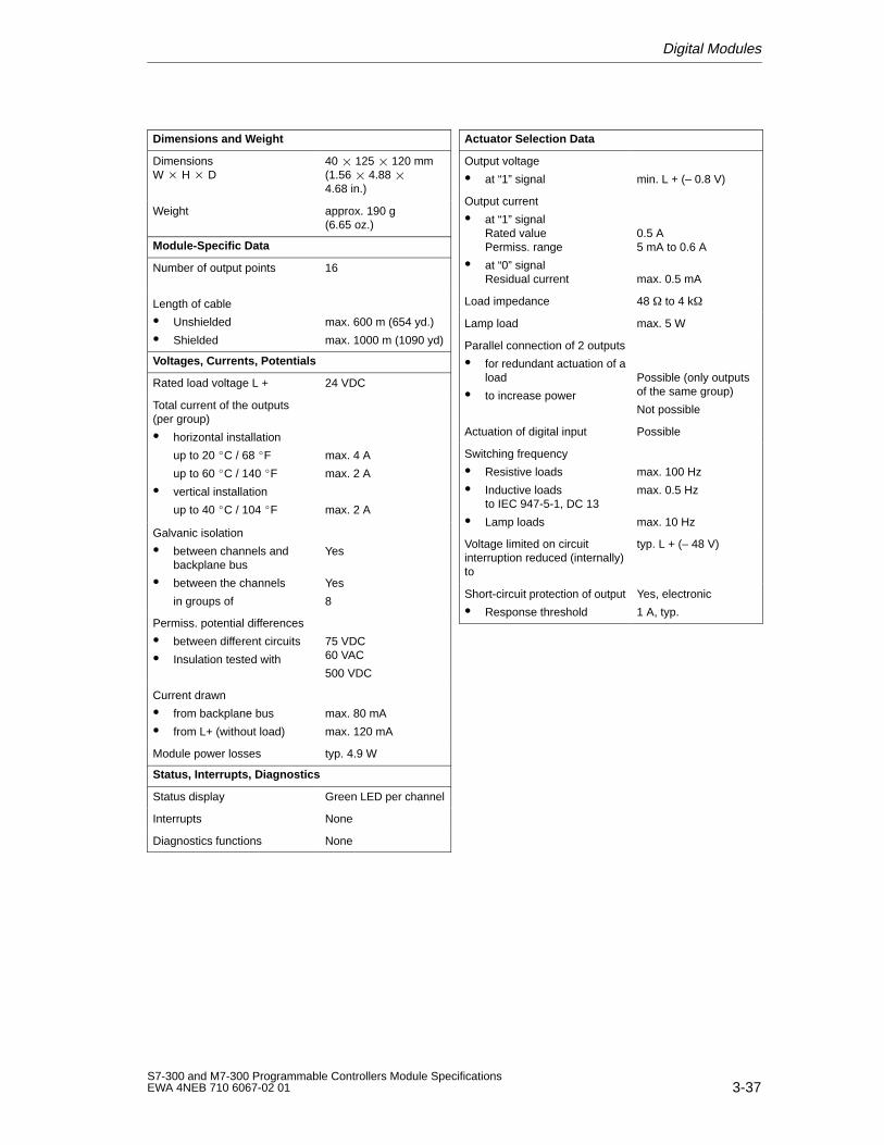
Digital Modules
3-37S7-300 and M7-300 Programmable Controllers Module SpecificationsEWA 4NEB 710 6067-02 01
Dimensions and W eight
Dimensions W H D
40 125 120 mm(1.56 4.88 4.68 in.)
Weight approx. 190 g(6.65 oz.)
Module-Specific Data
Number of output points 16
Length of cable
Unshielded
Shielded
max. 600 m (654 yd.)
max. 1000 m (1090 yd)
Voltages, Currents, Potentials
Rated load voltage L + 24 VDC
Total current of the outputs(per group)
horizontal installation
up to 20 C / 68 F
up to 60 C / 140 F
vertical installation
up to 40 C / 104 F
max. 4 A
max. 2 A
max. 2 A
Galvanic isolation
between channels andbackplane bus
between the channels
in groups of
Yes
Yes
8
Permiss. potential differences
between different circuits
Insulation tested with
75 VDC60 VAC
500 VDC
Current drawn
from backplane bus
from L+ (without load)
max. 80 mA
max. 120 mA
Module power losses typ. 4.9 W
Status, Interrupts, Diagnostics
Status display Green LED per channel
Interrupts None
Diagnostics functions None
Actuator Selection Data
Output voltage
at “1” signal min. L + (– 0.8 V)
Output current
at “1” signalRated valuePermiss. range
at “0” signalResidual current
0.5 A5 mA to 0.6 A
max. 0.5 mA
Load impedance 48 to 4 k
Lamp load max. 5 W
Parallel connection of 2 outputs
for redundant actuation of aload
to increase power
Possible (only outputsof the same group)
Not possible
Actuation of digital input Possible
Switching frequency
Resistive loads
Inductive loadsto IEC 947-5-1, DC 13
Lamp loads
max. 100 Hz
max. 0.5 Hz
max. 10 Hz
Voltage limited on circuitinterruption reduced (internally)to
typ. L + (– 48 V)
Short-circuit protection of output
Response threshold
Yes, electronic
1 A, typ.
Digital Modules
3-38S7-300 and M7-300 Programmable Controllers Module Specifications
EWA 4NEB 710 6067-02 01
3.2.3 Digital Output Module SM 322; DO 8 24 VDC/0.5 A;with Diagnostics Interrupt
Order No.
6ES7 322-8BF00-0AB0
Characteristics
The digital output module SM 322; DO 824 VDC/0.5 A; with diagnostics interrupthas the following salient features:
8 output points, isolated in groups of 8
0.5 A output current
24 VDC rated load voltage
Suitable for solenoid valves, DC contactors and signal lights
2 terminals per output
– Output without series diode
– Output with series diode (for redundant load control)
Configurable diagnostics
Configurable diagnostics interrupt
Configurable substitute value output
Group fault LED
Channel-specific status and error LEDs
Use in
This I/O modules can be used in the
S7-300 (centralized configuration) with the CPU312 IFM from 6ES7 312-5AC00-0AB0, revision level 5313 from 6ES7 313-1AD00-0AB0, revision level 3314 from 6ES7 314-1AE01-0AB0, revision level 6314 IFM from 6ES7 314-5AE00-0AB0, revision level 1315 from 6ES7 315-1AF00-0AB0, revision level 3315-2 from 6ES7 315-2AF00-0AB0, revision level 3614 from 6ES7 614-1AH01-0AB3, revision level 6.
ET 200M with theIM 153-1 from 6ES7 153-1AA02-0XB0, revision level 1IM 153-2 from 6ES7 153-2Ax00-0XB0, revision level 1IM 153-3 from 6ES7 153-3AA00-0XB0, revision level 1and with the following DP masters :IM 308C from 6ES5 308-3UC11, revision level 3, andCPUs 41x from 6ES7 41x-2XG00-0AB0; revision level 2.
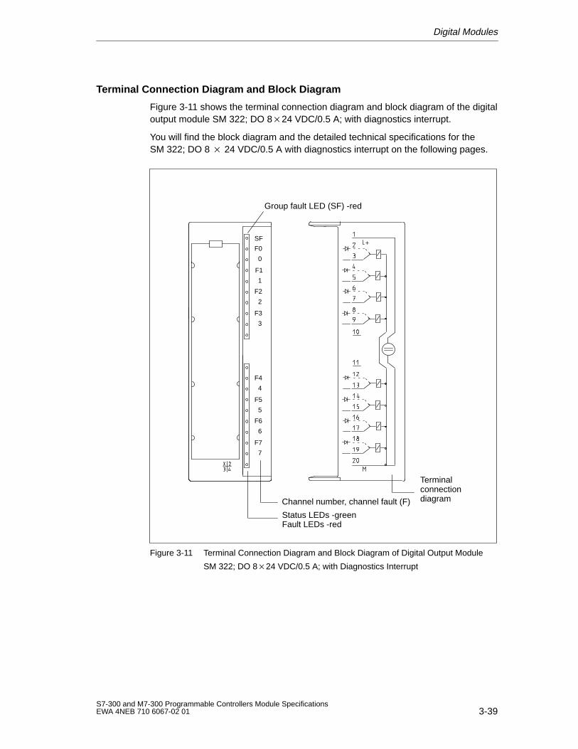
Digital Modules
3-39S7-300 and M7-300 Programmable Controllers Module SpecificationsEWA 4NEB 710 6067-02 01
Terminal Connection Diagram and Block Diagram
Figure 3-11 shows the terminal connection diagram and block diagram of the digitaloutput module SM 322; DO 824 VDC/0.5 A; with diagnostics interrupt.
You will find the block diagram and the detailed technical specifications for theSM 322; DO 8 24 VDC/0.5 A with diagnostics interrupt on the following pages.
Channel number, channel fault (F)
Status LEDs -green
SF
F0
0
F1
1
F2
2
F3
3
F4
4
F5
5
F6
6
F7
7
Fault LEDs -red
Terminalconnectiondiagram
Group fault LED (SF) -red
Figure 3-11 Terminal Connection Diagram and Block Diagram of Digital Output Module
SM 322; DO 824 VDC/0.5 A; with Diagnostics Interrupt
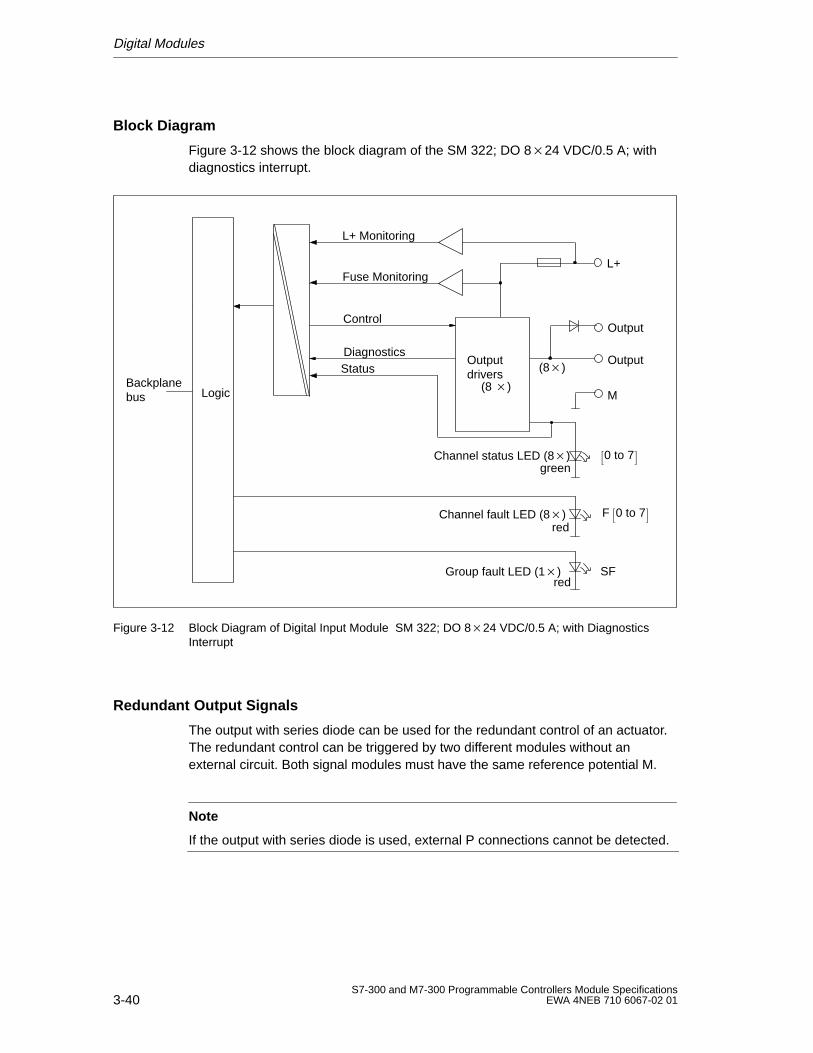
Digital Modules
3-40S7-300 and M7-300 Programmable Controllers Module Specifications
EWA 4NEB 710 6067-02 01
Block Diagram
Figure 3-12 shows the block diagram of the SM 322; DO 824 VDC/0.5 A; withdiagnostics interrupt.
L+
green
L+ Monitoring
Fuse Monitoring
Control
redGroup fault LED (1)
redChannel fault LED (8)
Channel status LED (8)
M
Output (8)
SF
DiagnosticsStatus
F 0 to 7
0 to 7
Outputdrivers
(8 )
Output
Backplanebus Logic
Figure 3-12 Block Diagram of Digital Input Module SM 322; DO 824 VDC/0.5 A; with DiagnosticsInterrupt
Redundant Output Signals
The output with series diode can be used for the redundant control of an actuator.The redundant control can be triggered by two different modules without anexternal circuit. Both signal modules must have the same reference potential M.
Note
If the output with series diode is used, external P connections cannot be detected.
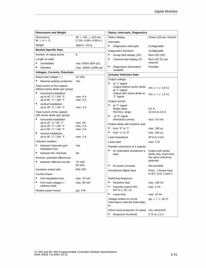
Digital Modules
3-41S7-300 and M7-300 Programmable Controllers Module SpecificationsEWA 4NEB 710 6067-02 01
Dimensions and W eight
Dimensions W H D
40 125 120 mm(1.564.884.68 in.)
Weight approx. 210 g
Module-Specific Data
Number of output points 8
Length of cable
Unshielded
Shielded
max. 600m (654 yd.)
max. 1000m (1090 yd)
Voltages, Currents, Potentials
Rated load voltage L +
Reverse polarity protection
24 VDC
Yes
Total current of the outputswithout series diode (per group)
horizontal installationup to 40 C / 104 Fup to 60 C / 140 F
vertical installationup to 40 C / 104 F
max. 4 Amax. 3 A
max. 4 A
Total current of the outputswith series diode (per group)
horizontal installationup to 20 C / 68 Fup to 40 C / 104 Fup to 60 C / 140 F
vertical installationup to 40 C / 104 F
max. 4Amax. 3 Amax. 2 A
max. 3 A
Galvanic isolation
between channels andbackplane bus
between the channels
Yes
No
Permiss. potential differences
between different circuits
Insulation tested with
75 VDC60 VAC
500 VDC
Current drawn
from backplane bus
from load voltage L+(without load)
max. 70 mA
max. 90 mA
Module power losses typ. 5 W
Status, Interrupts, Diagnostics
Status display Green LED per channel
Interrupts
Diagnostics interrupts Configurable
Diagnostics functions
Group fault display (SF)
Channel fault display (F)
Diagnostics informationreadable
Configurable
Red LED (SF)
Red LED (F) perchannel
Possible
Actuator Selection Data
Output voltage
at “1” signalOutput without series diodeat “1” signalOutput with series diode at“1” signal
min. L + (– 0.8 V)
min. L + (– 1.6 V)
Output current
at “1” signalRated valuePermiss. range
at “0” signal(Residual current)
0.5 A10 mA to 0.6 A
max. 0.5 mA
Output delay with resistive load
from “0” to “1”
from “1” to “0”
max. 180 s
max. 245 s
Load impedance 48 to 3 k
Lamp load max. 5 W
Parallel connection of 2 outputs
for redundant actuationof aload
for power increase
Output with seriesdiode only, must havethe same referencepotential
Not possible
Actuationof digital input Poss., 1 binary inputto IEC 1131 2 type 2
Switching frequency
Resistive load
Inductive load to IEC947-5-1, DC 13
Lamp load
max. 100 Hz
max. 2 Hz
max. 10 Hz
Voltage limited on circuitinterruption reduced (internally)to
typ. L + (– 45 V)
Short-circuit protection of output
Response threshold
Yes, electronic
0.75 to 1.5 A
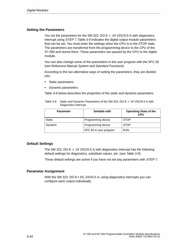
Digital Modules
3-42S7-300 and M7-300 Programmable Controllers Module Specifications
EWA 4NEB 710 6067-02 01
Setting the Parameters
You set the parameters for the SM 322; DO 8 24 VDC/0.5 A with diagnosticsinterrupt using STEP 7. Table 3-9 indicates the digital output module parametersthat can be set. You must enter the settings when the CPU is in the STOP state.The parameters are transferred from the programming device to the CPU of theS7-300 and stored there. These parameters are passed by the CPU to the digitalmodule.
You can also change some of the parameters in the user program with the SFC 55(see Reference Manual System and Standard Functions).
According to the two alternative ways of setting the parameters, they are dividedinto:
Static parameters
Dynamic parameters
Table 3-8 below describes the properties of the static and dynamic parameters.
Table 3-8 Static and Dynamic Parameters of the SM 322; DO 8 24 VDC/0.5 A withDiagnostics Interrupt
Parameter Settable with Operating State of theCPU
Static Programming device STOP
Dynamic Programming device STOPy
SFC 55 in user program RUN
Default Settings
The SM 322; DO 8 24 VDC/0.5 A with diagnostics interrupt has the followingdefault settings for diagnostics, substitute values, etc. (see Table 3-9).
These default settings are active if you have not set any parameters with STEP 7.
Parameter Assignment
With the SM 322; DO 8DC 24V/0.5 A; using diagnostics interrupts you canconfigure each output individually.
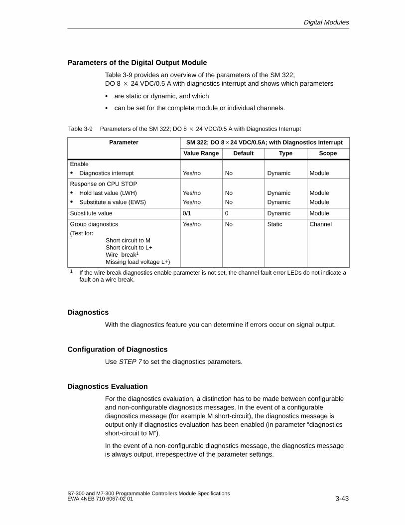
Digital Modules
3-43S7-300 and M7-300 Programmable Controllers Module SpecificationsEWA 4NEB 710 6067-02 01
Parameters of the Digital Output Module
Table 3-9 provides an overview of the parameters of the SM 322; DO 8 24 VDC/0.5 A with diagnostics interrupt and shows which parameters
are static or dynamic, and which
can be set for the complete module or individual channels.
Table 3-9 Parameters of the SM 322; DO 8 24 VDC/0.5 A with Diagnostics Interrupt
Parameter SM 322; DO 824 VDC/0.5A; with Diagnostics Interrupt
Value Range Default Type Scope
Enable
Diagnostics interrupt Yes/no No Dynamic Module
Response on CPU STOP
Hold last value (LWH)
Substitute a value (EWS)
Yes/no
Yes/no
No
No
Dynamic
Dynamic
Module
Module
Substitute value 0/1 0 Dynamic Module
Group diagnostics
(Test for:Short circuit to MShort circuit to L+Wire break1
Missing load voltage L+)
Yes/no No Static Channel
1 If the wire break diagnostics enable parameter is not set, the channel fault error LEDs do not indicate afault on a wire break.
Diagnostics
With the diagnostics feature you can determine if errors occur on signal output.
Configuration of Diagnostics
Use STEP 7 to set the diagnostics parameters.
Diagnostics Evaluation
For the diagnostics evaluation, a distinction has to be made between configurableand non-configurable diagnostics messages. In the event of a configurablediagnostics message (for example M short-circuit), the diagnostics message isoutput only if diagnostics evaluation has been enabled (in parameter “diagnosticsshort-circuit to M”).
In the event of a non-configurable diagnostics message, the diagnostics messageis always output, irrepespective of the parameter settings.
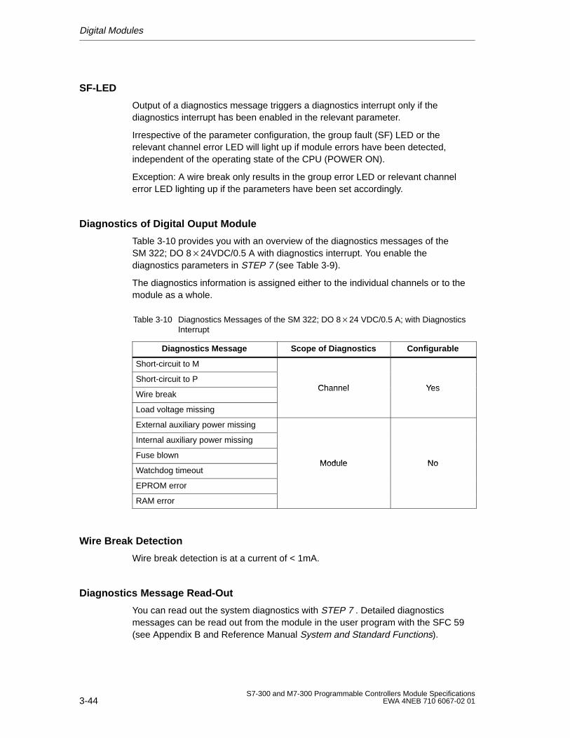
Digital Modules
3-44S7-300 and M7-300 Programmable Controllers Module Specifications
EWA 4NEB 710 6067-02 01
SF-LED
Output of a diagnostics message triggers a diagnostics interrupt only if thediagnostics interrupt has been enabled in the relevant parameter.
Irrespective of the parameter configuration, the group fault (SF) LED or therelevant channel error LED will light up if module errors have been detected,independent of the operating state of the CPU (POWER ON).
Exception: A wire break only results in the group error LED or relevant channelerror LED lighting up if the parameters have been set accordingly.
Diagnostics of Digital Ouput Module
Table 3-10 provides you with an overview of the diagnostics messages of theSM 322; DO 824VDC/0.5 A with diagnostics interrupt. You enable thediagnostics parameters in STEP 7 (see Table 3-9).
The diagnostics information is assigned either to the individual channels or to themodule as a whole.
Table 3-10 Diagnostics Messages of the SM 322; DO 824 VDC/0.5 A; with DiagnosticsInterrupt
Diagnostics Message Scope of Diagnostics Configurable
Short-circuit to M
Short-circuit to PChannel Yes
Wire breakChannel Yes
Load voltage missing
External auxiliary power missing
Internal auxiliary power missing
Fuse blownModule No
Watchdog timeoutModule No
EPROM error
RAM error
Wire Break Detection
Wire break detection is at a current of < 1mA.
Diagnostics Message Read-Out
You can read out the system diagnostics with STEP 7 . Detailed diagnosticsmessages can be read out from the module in the user program with the SFC 59(see Appendix B and Reference Manual System and Standard Functions).
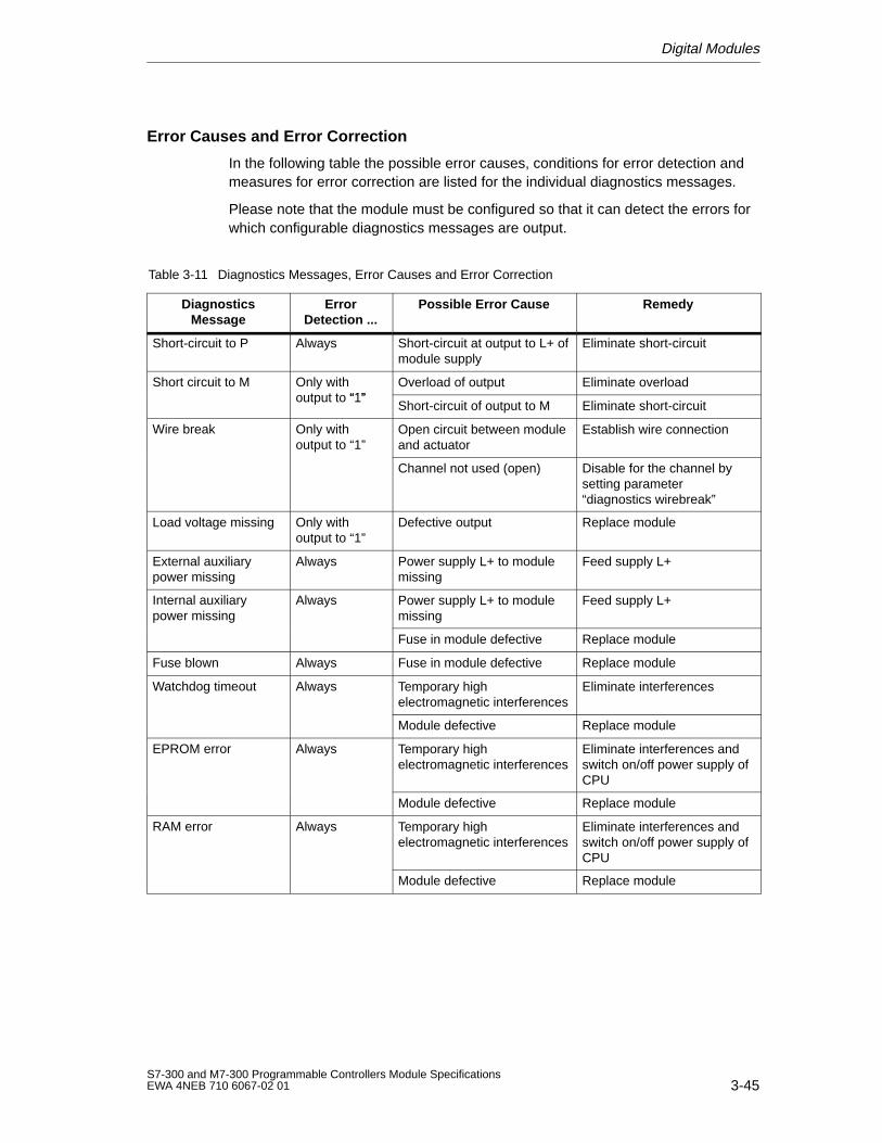
Digital Modules
3-45S7-300 and M7-300 Programmable Controllers Module SpecificationsEWA 4NEB 710 6067-02 01
Error Causes and Error Correction
In the following table the possible error causes, conditions for error detection andmeasures for error correction are listed for the individual diagnostics messages.
Please note that the module must be configured so that it can detect the errors forwhich configurable diagnostics messages are output.
Table 3-11 Diagnostics Messages, Error Causes and Error Correction
DiagnosticsMessage
ErrorDetection ...
Possible Error Cause Remedy
Short-circuit to P Always Short-circuit at output to L+ ofmodule supply
Eliminate short-circuit
Short circuit to M Only withoutput to “1”
Overload of output Eliminate overloadyoutput to “1”
Short-circuit of output to M Eliminate short-circuit
Wire break Only withoutput to “1”
Open circuit between moduleand actuator
Establish wire connectionp
Channel not used (open) Disable for the channel bysetting parameter“diagnostics wirebreak”
Load voltage missing Only withoutput to “1”
Defective output Replace module
External auxiliarypower missing
Always Power supply L+ to modulemissing
Feed supply L+
Internal auxiliarypower missing
Always Power supply L+ to modulemissing
Feed supply L+p g
Fuse in module defective Replace module
Fuse blown Always Fuse in module defective Replace module
Watchdog timeout Always Temporary highelectromagnetic interferences
Eliminate interferences
Module defective Replace module
EPROM error Always Temporary highelectromagnetic interferences
Eliminate interferences andswitch on/off power supply ofCPU
Module defective Replace module
RAM error Always Temporary highelectromagnetic interferences
Eliminate interferences andswitch on/off power supply ofCPU
Module defective Replace module
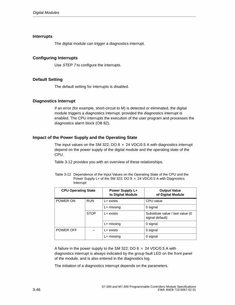
Digital Modules
3-46S7-300 and M7-300 Programmable Controllers Module Specifications
EWA 4NEB 710 6067-02 01
Interrupts
The digital module can trigger a diagnostics interrupt.
Configuring Interrupts
Use STEP 7 to configure the interrupts.
Default Setting
The default setting for interrupts is disabled.
Diagnostics Interrupt
If an error (for example, short-circuit to M) is detected or eliminated, the digitalmodule triggers a diagnostics interrupt, provided the diagnostics interrupt isenabled. The CPU interrupts the execution of the user program and processes thediagnostics alarm block (OB 82).
Impact of the Power Supply and the Operating State
The input values on the SM 322; DO 8 24 VDC/0.5 A with diagnostics interruptdepend on the power supply of the digital module and the operating state of theCPU.
Table 3-12 provides you with an overview of these relationships.
Table 3-12 Dependence of the Input Values on the Operating State of the CPU and thePower Supply L+ of the SM 322; DO 8 24 VDC/0.5 A with DiagnosticsInterrupt
CPU Operating State Power Supply L+to Digital Module
Output Valueof Digital Module
POWER ON RUN L+ exists CPU value
L+ missing 0 signal
STOP L+ exists Substitute value / last value (0signal default)
L+ missing 0 signal
POWER OFF – L+ exists 0 signal
L+ missing 0 signal
A failure in the power supply to the SM 322; DO 8 24 VDC/0.5 A withdiagnostics interrupt is always indicated by the group fault LED on the front panelof the module, and is also entered in the diagnostics log.
The initiation of a diagnostics interrupt depends on the parameters.
Digital Modules
3-47S7-300 and M7-300 Programmable Controllers Module SpecificationsEWA 4NEB 710 6067-02 01
3.2.4 Digital Output Module SM 322; DO 8 24 VDC/2 A
Order No.
322-1BF01-0AA0
Characteristics
The digital output module SM 322; DO 8 24VDC/2 A has the following salientfeatures.
8 output points, isolated in groups of 4
2 A output current
24 VDC rated load voltage
Suitable for solenoid valves, DC contactors and indicator lights.
Special Feature
When the power supply is switched on via a mechanical contact, the digital outputmodule SM 322; DO 8 24 VDC/2 A sends a “1” signal to its outputs forapproximately 50 s. You must observe this when using the digital output moduleSM 322; DO 8 24 VDC/2 A for high-speed counters!
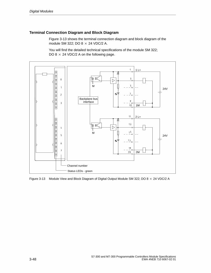
Digital Modules
3-48S7-300 and M7-300 Programmable Controllers Module Specifications
EWA 4NEB 710 6067-02 01
Terminal Connection Diagram and Block Diagram
Figure 3-13 shows the terminal connection diagram and block diagram of themodule SM 322; DO 8 24 VDC/2 A.
You will find the detailed technical specifications of the module SM 322;DO 8 24 VDC/2 A on the following page.
Channel number
Status LEDs - green
Backplane businterface
1M
M24V
1 L+
2M
M24V
2 L+
Figure 3-13 Module View and Block Diagram of Digital Output Module SM 322; DO 8 24 VDC/2 A
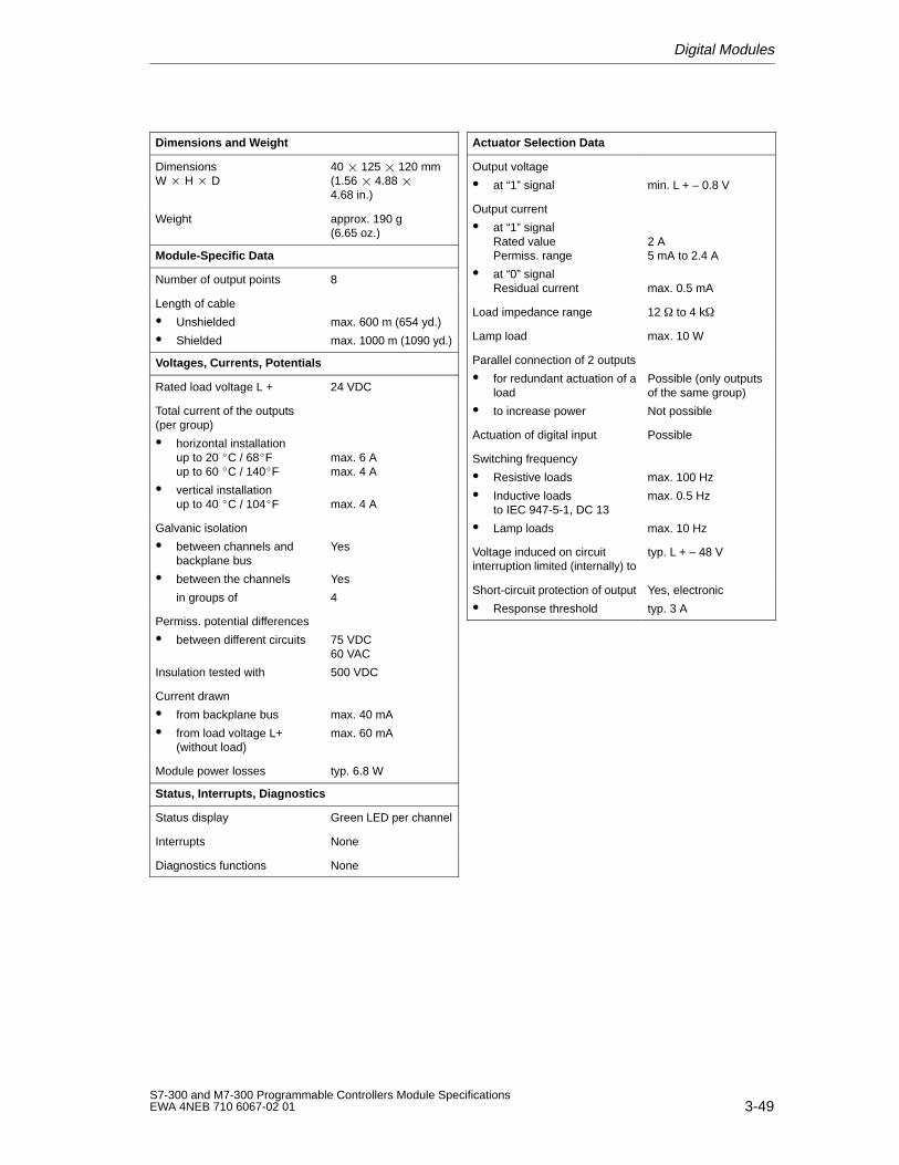
Digital Modules
3-49S7-300 and M7-300 Programmable Controllers Module SpecificationsEWA 4NEB 710 6067-02 01
Dimensions and W eight
Dimensions W H D
40 125 120 mm(1.56 4.88 4.68 in.)
Weight approx. 190 g (6.65 oz.)
Module-Specific Data
Number of output points 8
Length of cable
Unshielded
Shielded
max. 600 m (654 yd.)
max. 1000 m (1090 yd.)
Voltages, Currents, Potentials
Rated load voltage L + 24 VDC
Total current of the outputs(per group)
horizontal installationup to 20 C / 68Fup to 60 C / 140F
vertical installationup to 40 C / 104F
max. 6 Amax. 4 A
max. 4 A
Galvanic isolation
between channels andbackplane bus
between the channels
in groups of
Yes
Yes
4
Permiss. potential differences
between different circuits
Insulation tested with
75 VDC60 VAC
500 VDC
Current drawn
from backplane bus
from load voltage L+(without load)
max. 40 mA
max. 60 mA
Module power losses typ. 6.8 W
Status, Interrupts, Diagnostics
Status display Green LED per channel
Interrupts None
Diagnostics functions None
Actuator Selection Data
Output voltage
at “1” signal min. L + – 0.8 V
Output current
at “1” signalRated valuePermiss. range
at “0” signalResidual current
2 A5 mA to 2.4 A
max. 0.5 mA
Load impedance range 12 to 4 k
Lamp load max. 10 W
Parallel connection of 2 outputs
for redundant actuation of aload
to increase power
Possible (only outputsof the same group)
Not possible
Actuation of digital input Possible
Switching frequency
Resistive loads
Inductive loadsto IEC 947-5-1, DC 13
Lamp loads
max. 100 Hz
max. 0.5 Hz
max. 10 Hz
Voltage induced on circuitinterruption limited (internally) to
typ. L + – 48 V
Short-circuit protection of output
Response threshold
Yes, electronic
typ. 3 A
Digital Modules
3-50S7-300 and M7-300 Programmable Controllers Module Specifications
EWA 4NEB 710 6067-02 01
3.2.5 Digital Output Module SM 322; DO 16 120 VAC/1 A
Order No.
6ES7 322-1EH01-0AA0
Characteristics
The digital output module SM 322; DO 16 120 VAC/1 A has the following salientfeatures:
16 output points, fused and isolated in groups of 8
1 A output current
120 VAC rated load voltage
Suitable for AC solenoid valves, contactors, motor starters, fractional h.p.motors and indicator lights.
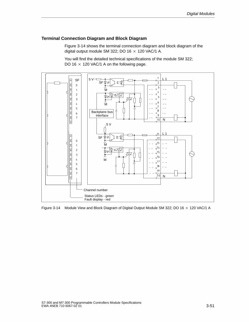
Digital Modules
3-51S7-300 and M7-300 Programmable Controllers Module SpecificationsEWA 4NEB 710 6067-02 01
Terminal Connection Diagram and Block Diagram
Figure 3-14 shows the terminal connection diagram and block diagram of thedigital output module SM 322; DO 16 120 VAC/1 A.
You will find the detailed technical specifications of the module SM 322;DO 16 120 VAC/1 A on the following page.
Channel number
Status LEDs - green
Backplane businterface
5 V
5 V
N
L 1
L 1
N
M
M
M
M
Fault display - red
SFSF
SF
Figure 3-14 Module View and Block Diagram of Digital Output Module SM 322; DO 16 120 VAC/1 A
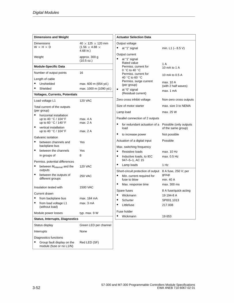
Digital Modules
3-52S7-300 and M7-300 Programmable Controllers Module Specifications
EWA 4NEB 710 6067-02 01
Dimensions and W eight
Dimensions W H D
40 125 120 mm(1.56 4.88 4.68 in.)
Weight approx. 300 g (10.5 oz.)
Module-Specific Data
Number of output points 16
Length of cable
Unshielded
Shielded
max. 600 m (654 yd.)
max. 1000 m (1090 yd.)
Voltages, Currents, Potentials
Load voltage L1 120 VAC
Total current of the outputs(per group)
horizontal installationup to 40 C / 104Fup to 60 C / 140F
vertical installationup to 40 C / 104F
max. 4 Amax. 2 A
max. 2 A
Galvanic isolation
between channels andbackplane bus
between the channels
in groups of
Yes
Yes
8
Permiss. potential differences
between Minternal and theoutputs
between the outputs ofdifferent groups
120 VAC
250 VAC
Insulation tested with 1500 VAC
Current drawn
from backplane bus
from load voltage L1(without load)
max. 184 mA
max. 3 mA
Module power losses typ. max. 9 W
Status, Interrupts, Diagnostics
Status display Green LED per channel
Interrupts None
Diagnostics functions
Group fault display on themodule (fuse or no L1/N)
Red LED (SF)
Actuator Selection Data
Output voltage
at “1” signal min. L1 (– 8.5 V)
Output current
at “1” signalRated valuePermiss. current for0 C to 40 CPermiss. current for40 C to 60 CPermiss. surge current(per group)
at “0” signal(Residual current)
1 A10 mA to 1 A
10 mA to 0.5 A
max. 10 A(with 2 half waves)
max. 1 mA
Zero cross inhibit voltage Non-zero cross outputs
Size of motor starter max. size 3 to NEMA
Lamp load max. 25 W
Parallel connection of 2 outputs
for redundant actuation of aload
Possible (only outputsof the same group)
to increase power Not possible
Actuation of a digital input Possible
Max. switching frequency
Resistive loads
Inductive loads, to IEC947–5–1, AC 15
Lamp loads
max. 10 Hz
max. 0.5 Hz
1 Hz
Short-circuit protection of output
Min. current required forfuse to blow
Max. response time
8 A fuse, 250 V; pergroup
min. 40 A
max. 300 ms
Spare fuses
Wickmann
Schurter
Littlefuse
8 A fuse/quick-acting
19 194-8 A
SP001.1013
217.008
Fuse holder
Wickmann 19 653
Digital Modules
3-53S7-300 and M7-300 Programmable Controllers Module SpecificationsEWA 4NEB 710 6067-02 01
3.2.6 Digital Output Module SM 322; DO 8 120/230 VAC/2 A
Order No.
6ES7 322-1FF01-0AA0
Characteristics
The digital output module SM 322; DO 8 120/230 VAC/2 A hasthe following salient features:
8 output points, fused and isolated in groups of 4
2 A output current
120/230 VAC rated load voltage
Suitable for AC solenoid valves, contactors, motor starters, fractional h.p.motors and lamps indicator lights.
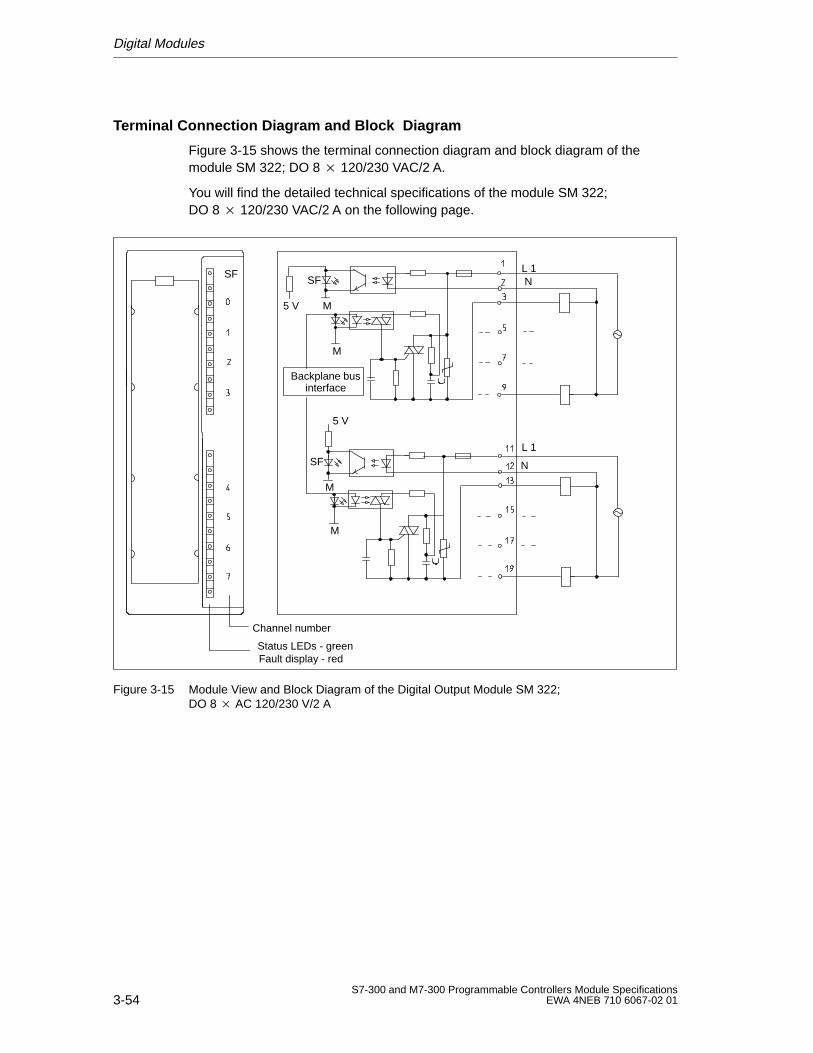
Digital Modules
3-54S7-300 and M7-300 Programmable Controllers Module Specifications
EWA 4NEB 710 6067-02 01
Terminal Connection Diagram and Block Diagram
Figure 3-15 shows the terminal connection diagram and block diagram of themodule SM 322; DO 8 120/230 VAC/2 A.
You will find the detailed technical specifications of the module SM 322;DO 8 120/230 VAC/2 A on the following page.
Backplane businterface
5 V
5 V
L 1
L 1
M
M
M
M
SF
SF N
N
Channel number
Status LEDs - greenFault display - red
SF
Figure 3-15 Module View and Block Diagram of the Digital Output Module SM 322; DO 8 AC 120/230 V/2 A
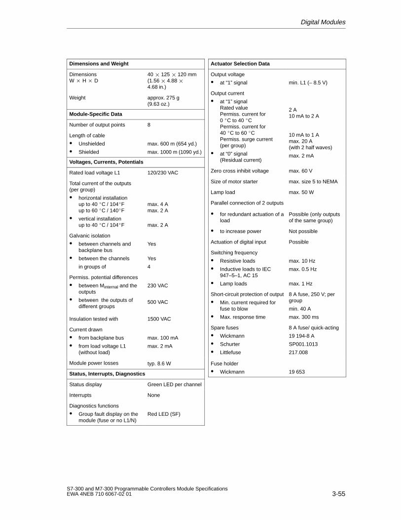
Digital Modules
3-55S7-300 and M7-300 Programmable Controllers Module SpecificationsEWA 4NEB 710 6067-02 01
Dimensions and W eight
Dimensions W H D
40 125 120 mm(1.56 4.88 4.68 in.)
Weight approx. 275 g(9.63 oz.)
Module-Specific Data
Number of output points 8
Length of cable
Unshielded
Shielded
max. 600 m (654 yd.)
max. 1000 m (1090 yd.)
Voltages, Currents, Potentials
Rated load voltage L1 120/230 VAC
Total current of the outputs(per group)
horizontal installationup to 40 C / 104Fup to 60 C / 140F
vertical installationup to 40 C / 104F
max. 4 Amax. 2 A
max. 2 A
Galvanic isolation
between channels andbackplane bus
between the channels
in groups of
Yes
Yes
4
Permiss. potential differences
between Minternal and theoutputs
between the outputs ofdifferent groups
230 VAC
500 VAC
Insulation tested with 1500 VAC
Current drawn
from backplane bus
from load voltage L1(without load)
max. 100 mA
max. 2 mA
Module power losses typ. 8.6 W
Status, Interrupts, Diagnostics
Status display Green LED per channel
Interrupts None
Diagnostics functions
Group fault display on themodule (fuse or no L1/N)
Red LED (SF)
Actuator Selection Data
Output voltage
at “1” signal min. L1 (– 8.5 V)
Output current
at “1” signalRated valuePermiss. current for0 C to 40 CPermiss. current for40 C to 60 CPermiss. surge current(per group)
at “0” signal(Residual current)
2 A10 mA to 2 A
10 mA to 1 Amax. 20 A(with 2 half waves)
max. 2 mA
Zero cross inhibit voltage max. 60 V
Size of motor starter max. size 5 to NEMA
Lamp load max. 50 W
Parallel connection of 2 outputs
for redundant actuation of aload
Possible (only outputsof the same group)
to increase power Not possible
Actuation of digital input Possible
Switching frequency
Resistive loads
Inductive loads to IEC947–5–1, AC 15
Lamp loads
max. 10 Hz
max. 0.5 Hz
max. 1 Hz
Short-circuit protection of output
Min. current required forfuse to blow
Max. response time
8 A fuse, 250 V; pergroup
min. 40 A
max. 300 ms
Spare fuses
Wickmann
Schurter
Littlefuse
8 A fuse/ quick-acting
19 194-8 A
SP001.1013
217.008
Fuse holder
Wickmann 19 653
Digital Modules
3-56S7-300 and M7-300 Programmable Controllers Module Specifications
EWA 4NEB 710 6067-02 01
3.2.7 Digital Output Module SM 322; D0 32 120 VAC/1.0 A
Order No.
6ES7 322-1EL00-0AA0
Characteristics
The digital output module, SM 322; DO 32 120 VAC/1.0 A has the followingsalient features:
32 output points, fused and isolated in groups of 8
1.0 A output current
120 VAC rated load voltage
Blown fuse indicator for each group
Suitable for AC solenoid valves, contactors, motor starters, fractional h.p.motors and indicator lights
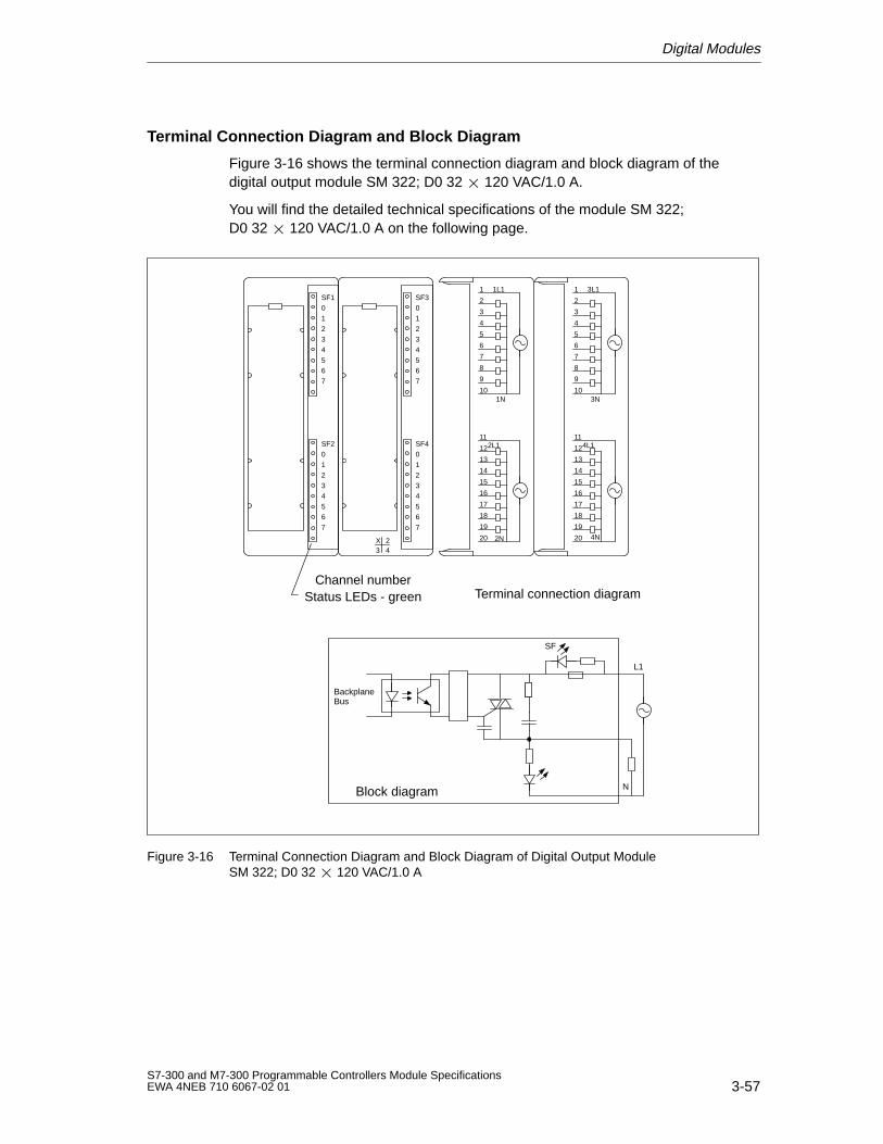
Digital Modules
3-57S7-300 and M7-300 Programmable Controllers Module SpecificationsEWA 4NEB 710 6067-02 01
Terminal Connection Diagram and Block Diagram
Figure 3-16 shows the terminal connection diagram and block diagram of thedigital output module SM 322; D0 32 120 VAC/1.0 A.
You will find the detailed technical specifications of the module SM 322; D0 32 120 VAC/1.0 A on the following page.
SF30
12
34
56
7
SF40
12
34
56
7
1
2
3
4
5
6
7
8
9
10
1L1
1N
11
12
13
14
15
16
17
18
19
20
2L1
2N24
X3
SF10
12
34
56
7
SF20
12
34
56
7
1
2
3
4
5
6
7
8
9
10
3L1
3N
11
12
13
14
15
16
17
18
19
20
4L1
4N
BackplaneBus
L1
SF
Block diagram
Channel numberStatus LEDs - green Terminal connection diagram
N
Figure 3-16 Terminal Connection Diagram and Block Diagram of Digital Output Module SM 322; D0 32 120 VAC/1.0 A
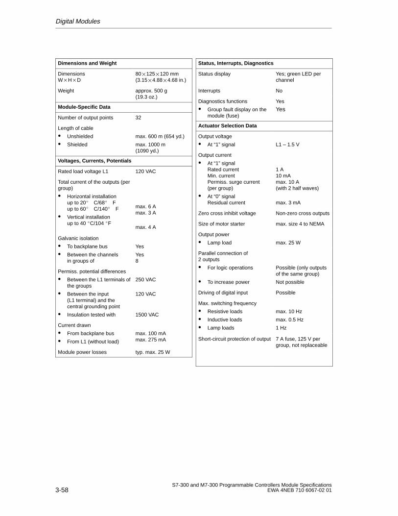
Digital Modules
3-58S7-300 and M7-300 Programmable Controllers Module Specifications
EWA 4NEB 710 6067-02 01
Dimensions and W eight
Dimensions WHD
80125120 mm(3.154.884.68 in.)
Weight approx. 500 g (19.3 oz.)
Module-Specific Data
Number of output points 32
Length of cable
Unshielded
Shielded
max. 600 m (654 yd.)
max. 1000 m (1090 yd.)
Voltages, Currents, Potentials
Rated load voltage L1 120 VAC
Total current of the outputs (pergroup)
Horizontal installationup to 20 C/68 Fup to 60 C/140 F
Vertical installationup to 40 C/104 F
max. 6 Amax. 3 A
max. 4 A
Galvanic isolation
To backplane bus
Between the channels in groups of
Yes
Yes8
Permiss. potential differences
Between the L1 terminals ofthe groups
Between the input (L1 terminal) and thecentral grounding point
Insulation tested with
250 VAC
120 VAC
1500 VAC
Current drawn
From backplane bus
From L1 (without load)
max. 100 mAmax. 275 mA
Module power losses typ. max. 25 W
Status, Interrupts, Diagnostics
Status display Yes; green LED perchannel
Interrupts No
Diagnostics functions
Group fault display on themodule (fuse)
Yes
Yes
Actuator Selection Data
Output voltage
At “1” signal L1 – 1.5 V
Output current
At “1” signalRated currentMin. currentPermiss. surge current(per group)
At “0” signal Residual current
1 A10 mAmax. 10 A(with 2 half waves)
max. 3 mA
Zero cross inhibit voltage Non-zero cross outputs
Size of motor starter max. size 4 to NEMA
Output power
Lamp load max. 25 W
Parallel connection of 2 outputs
For logic operations
To increase power
Possible (only outputsof the same group)
Not possible
Driving of digital input Possible
Max. switching frequency
Resistive loads
Inductive loads
Lamp loads
max. 10 Hz
max. 0.5 Hz
1 Hz
Short-circuit protection of output 7 A fuse, 125 V pergroup, not replaceable
Digital Modules
3-59S7-300 and M7-300 Programmable Controllers Module SpecificationsEWA 4NEB 710 6067-02 01
3.3 Relay Output Modules
List of Relay Output Modules
The following relay output modules are described in this chapter.
SM 322; DO 16 120 VAC REL.
SM 322; DO 8 230 VAC REL.
SM 322; DO 8 230 VAC/5A REL.
3.3.1 Relay Output Module SM 322; DO 16 120 VAC REL.
Order No.
6ES7 322-1HH00-0AA0
Characteristics
The relay output module SM 322; DO 16 120 VAC REL. has the followingsalient features:
16 output points, isolated in groups of 8
Load voltage 24 VDC to 120 VDC, 48 VAC to 120 VAC
Suitable for AC/DC solenoid valves, contactors, motor starters, fractional h.p.motors and indicator lights.
Note
When the power supply is switched off, the capacitor still stores energy for about200 ms. The relay can therefore still be driven briefly within this time by the userprogram.
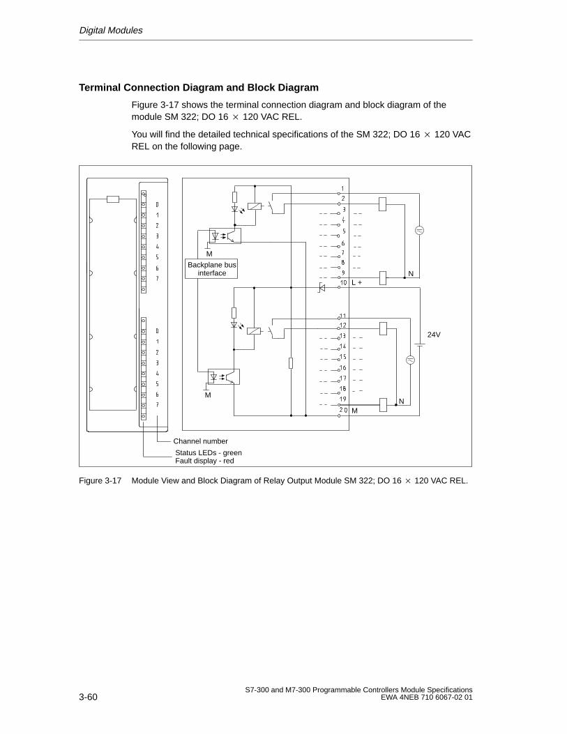
Digital Modules
3-60S7-300 and M7-300 Programmable Controllers Module Specifications
EWA 4NEB 710 6067-02 01
Terminal Connection Diagram and Block Diagram
Figure 3-17 shows the terminal connection diagram and block diagram of themodule SM 322; DO 16 120 VAC REL.
You will find the detailed technical specifications of the SM 322; DO 16 120 VACREL on the following page.
Channel number
Status LEDs - green
L +N
Fault display - red
M
M
Backplane businterface
NM
24V
Figure 3-17 Module View and Block Diagram of Relay Output Module SM 322; DO 16 120 VAC REL.
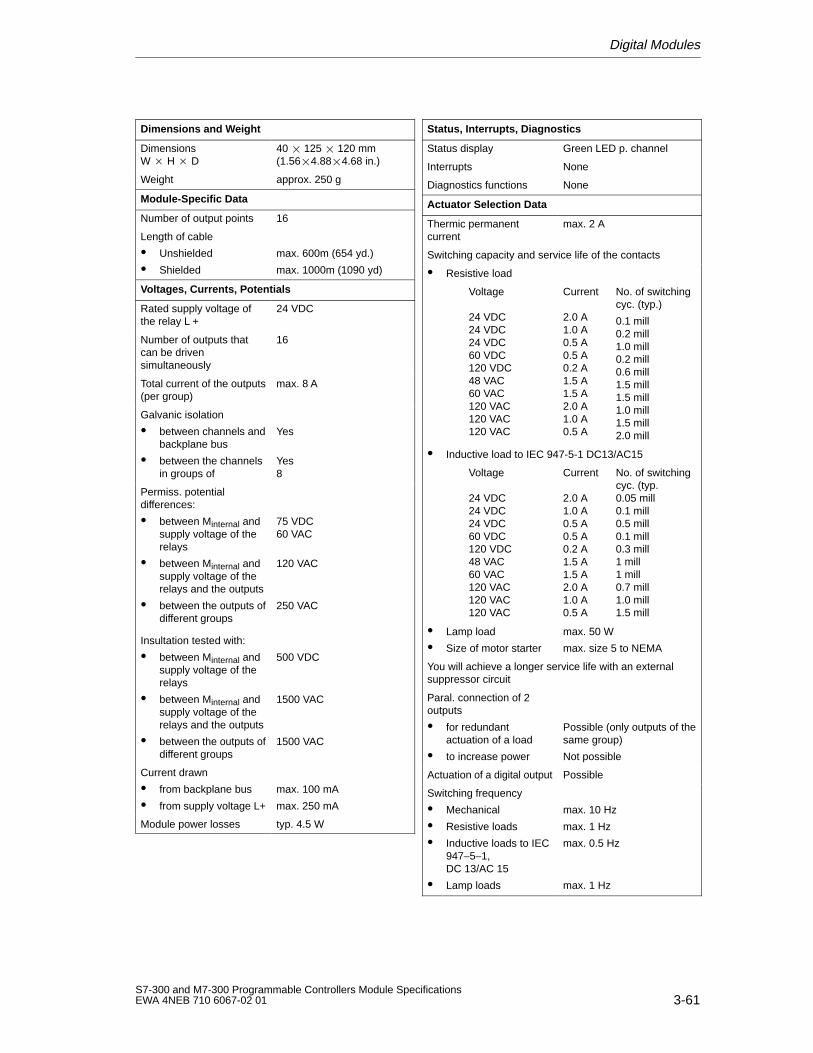
Digital Modules
3-61S7-300 and M7-300 Programmable Controllers Module SpecificationsEWA 4NEB 710 6067-02 01
Dimensions and W eight
Dimensions W H D
40 125 120 mm(1.564.884.68 in.)
Weight approx. 250 g
Module-Specific Data
Number of output points 16
Length of cable
Unshielded
Shielded
max. 600m (654 yd.)
max. 1000m (1090 yd)
Voltages, Currents, Potentials
Rated supply voltage ofthe relay L +
24 VDC
Number of outputs thatcan be drivensimultaneously
16
Total current of the outputs(per group)
max. 8 A
Galvanic isolation
between channels andbackplane bus
between the channelsin groups of
Yes
Yes8
Permiss. potentialdifferences:
between Minternal andsupply voltage of therelays
between Minternal andsupply voltage of therelays and the outputs
between the outputs ofdifferent groups
75 VDC60 VAC
120 VAC
250 VAC
Insultation tested with:
between Minternal andsupply voltage of therelays
between Minternal andsupply voltage of therelays and the outputs
between the outputs ofdifferent groups
500 VDC
1500 VAC
1500 VAC
Current drawn
from backplane bus
from supply voltage L+
max. 100 mA
max. 250 mA
Module power losses typ. 4.5 W
Status, Interrupts, Diagnostics
Status display Green LED p. channel
Interrupts None
Diagnostics functions None
Actuator Selection Data
Thermic permanentcurrent
max. 2 A
Switching capacity and service life of the contacts
Resistive load
Voltage
24 VDC24 VDC24 VDC60 VDC120 VDC48 VAC60 VAC120 VAC120 VAC120 VAC
Current
2.0 A1.0 A0.5 A0.5 A0.2 A1.5 A1.5 A2.0 A1.0 A0.5 A
No. of switchingcyc. (typ.)
0.1 mill0.2 mill1.0 mill0.2 mill0.6 mill1.5 mill1.5 mill1.0 mill1.5 mill2.0 mill
Inductive load to IEC 947-5-1 DC13/AC15
Voltage
24 VDC24 VDC24 VDC60 VDC120 VDC48 VAC60 VAC120 VAC120 VAC120 VAC
Current
2.0 A1.0 A0.5 A0.5 A0.2 A1.5 A1.5 A2.0 A1.0 A0.5 A
No. of switchingcyc. (typ.0.05 mill0.1 mill0.5 mill0.1 mill0.3 mill1 mill1 mill0.7 mill1.0 mill1.5 mill
Lamp load
Size of motor starter
max. 50 W
max. size 5 to NEMA
You will achieve a longer service life with an externalsuppressor circuit
Paral. connection of 2outputs
for redundantactuation of a load
to increase power
Possible (only outputs of thesame group)
Not possible
Actuation of a digital output Possible
Switching frequency
Mechanical
Resistive loads
Inductive loads to IEC947–5–1, DC 13/AC 15
Lamp loads
max. 10 Hz
max. 1 Hz
max. 0.5 Hz
max. 1 Hz
Digital Modules
3-62S7-300 and M7-300 Programmable Controllers Module Specifications
EWA 4NEB 710 6067-02 01
3.3.2 Relay Output Module SM 322; DO 8 230 VAC REL.
Order No.
6ES7 322-1HF00-0AA0
Characteristics
The relay output module SM 322; DO 8 230 VAC REL. has the following salientfeatures:
8 output points, isolated in groups of 2
Rated load voltage 24 VDC to 120 VDC, 48VAC to 230VAC
Suitable for AC/DC solenoid valves, contactors, motor starters, fractional h.p.motors and indicator lights.
Note
When the power supply is switched off, the capacitor still stores energy for about200 ms. The relay can therefore still be driven briefly within this time by the userprogram.
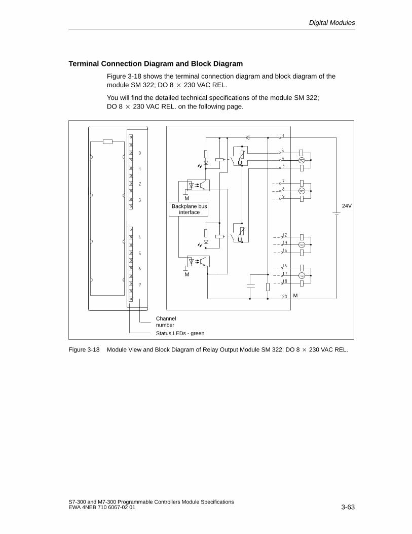
Digital Modules
3-63S7-300 and M7-300 Programmable Controllers Module SpecificationsEWA 4NEB 710 6067-02 01
Terminal Connection Diagram and Block Diagram
Figure 3-18 shows the terminal connection diagram and block diagram of themodule SM 322; DO 8 230 VAC REL.
You will find the detailed technical specifications of the module SM 322; DO 8 230 VAC REL. on the following page.
Status LEDs - green
Channelnumber
U
M
Backplane businterface
M
U
24V
M
Figure 3-18 Module View and Block Diagram of Relay Output Module SM 322; DO 8 230 VAC REL.
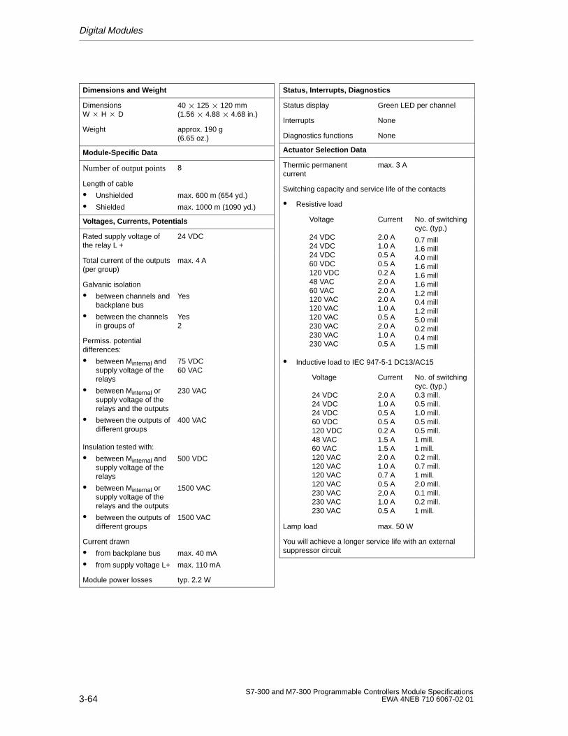
Digital Modules
3-64S7-300 and M7-300 Programmable Controllers Module Specifications
EWA 4NEB 710 6067-02 01
Dimensions and W eight
Dimensions W H D
40 125 120 mm(1.56 4.88 4.68 in.)
Weight approx. 190 g (6.65 oz.)
Module-Specific Data
Number of output points 8
Length of cable
Unshielded
Shielded
max. 600 m (654 yd.)
max. 1000 m (1090 yd.)
Voltages, Currents, Potentials
Rated supply voltage ofthe relay L +
24 VDC
Total current of the outputs(per group)
max. 4 A
Galvanic isolation
between channels andbackplane bus
between the channelsin groups of
Yes
Yes2
Permiss. potentialdifferences:
between Minternal andsupply voltage of therelays
between Minternal orsupply voltage of therelays and the outputs
between the outputs ofdifferent groups
75 VDC60 VAC
230 VAC
400 VAC
Insulation tested with:
between Minternal andsupply voltage of therelays
between Minternal orsupply voltage of therelays and the outputs
between the outputs ofdifferent groups
500 VDC
1500 VAC
1500 VAC
Current drawn
from backplane bus
from supply voltage L+
max. 40 mA
max. 110 mA
Module power losses typ. 2.2 W
Status, Interrupts, Diagnostics
Status display Green LED per channel
Interrupts None
Diagnostics functions None
Actuator Selection Data
Thermic permanentcurrent
max. 3 A
Switching capacity and service life of the contacts
Resistive load
Voltage
24 VDC24 VDC24 VDC60 VDC120 VDC48 VAC60 VAC120 VAC120 VAC120 VAC230 VAC230 VAC230 VAC
Current
2.0 A1.0 A0.5 A0.5 A0.2 A2.0 A2.0 A2.0 A1.0 A0.5 A2.0 A1.0 A0.5 A
No. of switchingcyc. (typ.)
0.7 mill1.6 mill4.0 mill1.6 mill1.6 mill1.6 mill1.2 mill0.4 mill1.2 mill5.0 mill0.2 mill0.4 mill1.5 mill
Inductive load to IEC 947-5-1 DC13/AC15
Voltage
24 VDC24 VDC24 VDC60 VDC120 VDC48 VAC60 VAC120 VAC 120 VAC120 VAC120 VAC230 VAC230 VAC230 VAC
Current
2.0 A1.0 A0.5 A0.5 A0.2 A1.5 A1.5 A2.0 A1.0 A0.7 A0.5 A2,0 A1.0 A0.5 A
No. of switchingcyc. (typ.)0.3 mill.0.5 mill.1.0 mill.0.5 mill.0.5 mill.1 mill.1 mill.0.2 mill.0.7 mill.1 mill.2.0 mill.0.1 mill.0.2 mill.1 mill.
Lamp load max. 50 W
You will achieve a longer service life with an externalsuppressor circuit
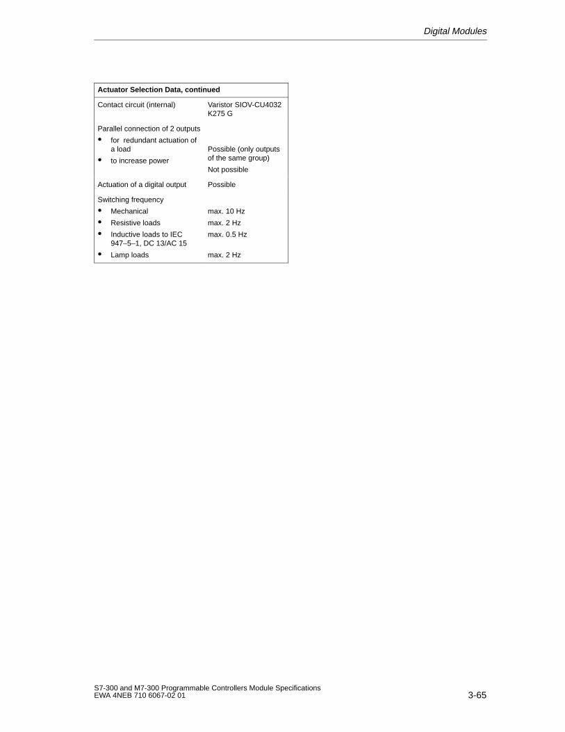
Digital Modules
3-65S7-300 and M7-300 Programmable Controllers Module SpecificationsEWA 4NEB 710 6067-02 01
Actuator Selection Data, continued
Contact circuit (internal) Varistor SIOV-CU4032K275 G
Parallel connection of 2 outputs
for redundant actuation ofa load
to increase power
Possible (only outputsof the same group)
Not possible
Actuation of a digital output Possible
Switching frequency
Mechanical
Resistive loads
Inductive loads to IEC947–5–1, DC 13/AC 15
Lamp loads
max. 10 Hz
max. 2 Hz
max. 0.5 Hz
max. 2 Hz
Digital Modules
3-66S7-300 and M7-300 Programmable Controllers Module Specifications
EWA 4NEB 710 6067-02 01
3.3.3 Digital output Module SM 322; DO 8 Rel. 230 VAC/5 A
Order No.
6ES7 322-1HF10-0AA0
Characteristics
The digital output module SM 322; DO 8Rel. 230 VAC/5 A has the followingfeatures:
8 outputs, isolated in groups of 1
Load current 24 V to 120 V DC, 48 V to 230 V AC
Suitable for AC/DC solenoid valves, contactors, motor starters, fractional h.p.motors and indicator lights
Note
In the case of currents greater than 3 A, a conductor cross-section of 1.5 mm2
must be selected in order to minimize the additional heating of the module at theconnector.
When the front-panel connector with spring-loaded terminals is implemented, theconnector with the order number 6ES7 392-1BM01-0AA0 must be used.
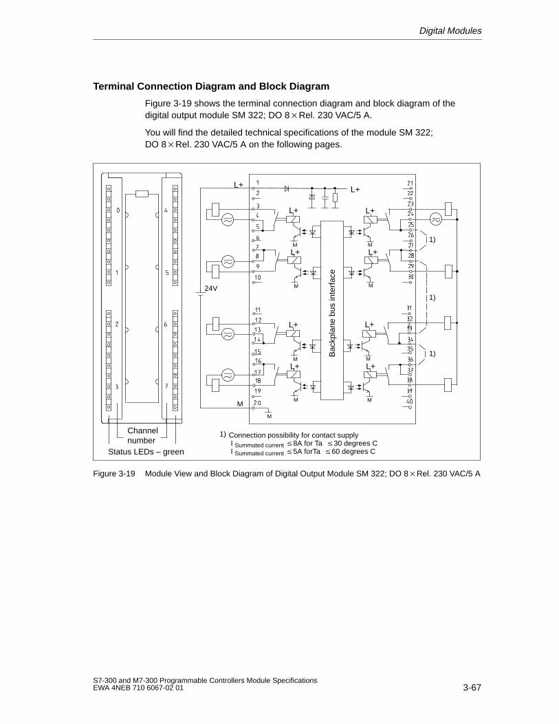
Digital Modules
3-67S7-300 and M7-300 Programmable Controllers Module SpecificationsEWA 4NEB 710 6067-02 01
Terminal Connection Diagram and Block Diagram
Figure 3-19 shows the terminal connection diagram and block diagram of thedigital output module SM 322; DO 8Rel. 230 VAC/5 A.
You will find the detailed technical specifications of the module SM 322; DO 8Rel. 230 VAC/5 A on the following pages.
Channelnumber
Status LEDs – green
L+
24V
M
L+
M
L+
M
L+
M M
L+M
L+
M
^
L+
M
L+
L+
M
M
Bac
kpla
ne b
us in
terf
ace
L+
1)
Connection possibility for contact supply I Summated current 8A for Ta 30 degrees C I Summated current 5A forTa 60 degrees C
1)
1)
1)
Figure 3-19 Module View and Block Diagram of Digital Output Module SM 322; DO 8Rel. 230 VAC/5 A
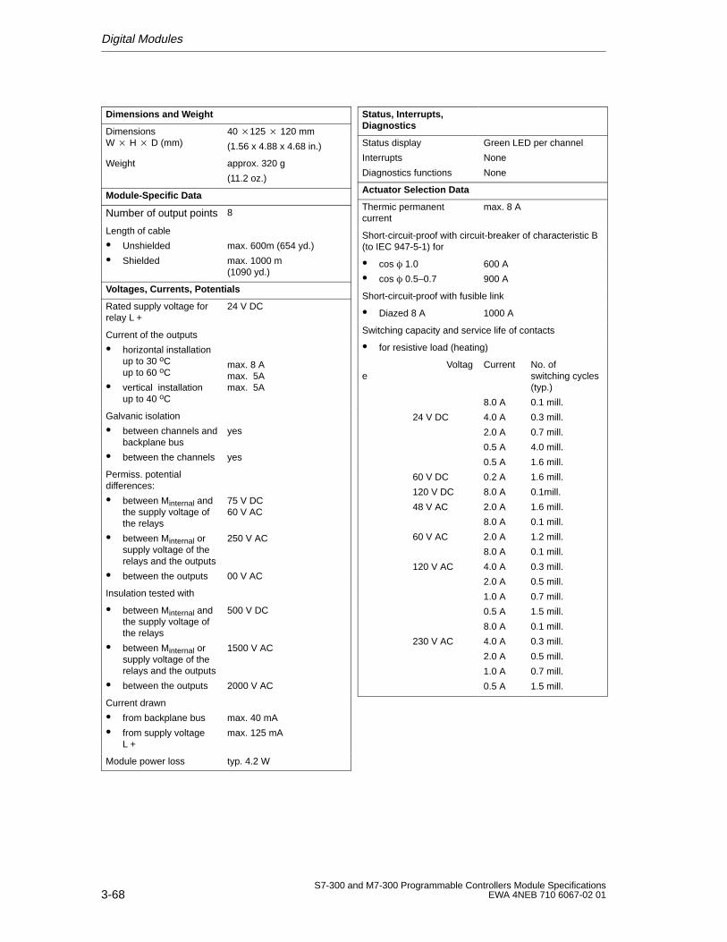
Digital Modules
3-68S7-300 and M7-300 Programmable Controllers Module Specifications
EWA 4NEB 710 6067-02 01
Dimensions and W eight
DimensionsW H D (mm)
40 125 120 mm
(1.56 x 4.88 x 4.68 in.)
Weight approx. 320 g
(11.2 oz.)
Module-Specific Data
Number of output points 8
Length of cable
Unshielded
Shielded
max. 600m (654 yd.)
max. 1000 m (1090 yd.)
Voltages, Currents, Potentials
Rated supply voltage forrelay L +
24 V DC
Current of the outputs
horizontal installation up to 30 oC up to 60 oC
vertical installationup to 40 oC
max. 8 Amax. 5Amax. 5A
Galvanic isolation
between channels andbackplane bus
between the channels
yes
yes
Permiss. potentialdifferences:
between Minternal andthe supply voltage ofthe relays
between Minternal orsupply voltage of therelays and the outputs
between the outputs
75 V DC60 V AC
250 V AC
00 V AC
Insulation tested with
between Minternal andthe supply voltage ofthe relays
between Minternal orsupply voltage of therelays and the outputs
between the outputs
500 V DC
1500 V AC
2000 V AC
Current drawn
from backplane bus
from supply voltageL +
max. 40 mA
max. 125 mA
Module power loss typ. 4.2 W
Status, Interrupts,Diagnostics
Status display
Interrupts
Diagnostics functions
Green LED per channel
None
None
Actuator Selection Data
Thermic permanentcurrent
max. 8 A
Short-circuit-proof with circuit-breaker of characteristic B(to IEC 947-5-1) for
cos 1.0
cos 0.5–0.7
600 A
900 A
Short-circuit-proof with fusible link
Diazed 8 A 1000 A
Switching capacity and service life of contacts
for resistive load (heating)
Voltage
24 V DC
60 V DC
120 V DC
48 V AC
60 V AC
120 V AC
230 V AC
Current
8.0 A
4.0 A
2.0 A
0.5 A
0.5 A
0.2 A
8.0 A
2.0 A
8.0 A
2.0 A
8.0 A
4.0 A
2.0 A
1.0 A
0.5 A
8.0 A
4.0 A
2.0 A
1.0 A
0.5 A
No. of switching cycles(typ.)
0.1 mill.
0.3 mill.
0.7 mill.
4.0 mill.
1.6 mill.
1.6 mill.
0.1mill.
1.6 mill.
0.1 mill.
1.2 mill.
0.1 mill.
0.3 mill.
0.5 mill.
0.7 mill.
1.5 mill.
0.1 mill.
0.3 mill.
0.5 mill.
0.7 mill.
1.5 mill.
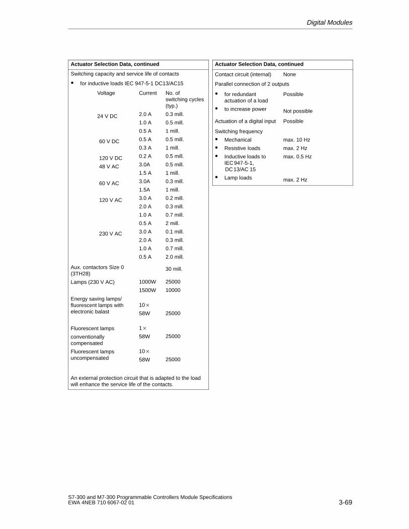
Digital Modules
3-69S7-300 and M7-300 Programmable Controllers Module SpecificationsEWA 4NEB 710 6067-02 01
Actuator Selection Data, continued
Switching capacity and service life of contacts
for inductive loads IEC 947-5-1 DC13/AC15
Voltage
24 V DC
60 V DC
120 V DC
48 V AC
60 V AC
120 V AC
230 V AC
Aux. contactors Size 0(3TH28)
Lamps (230 V AC)
Energy saving lamps/fluorescent lamps withelectronic balast
Fluorescent lamps
conventionally compensated
Fluorescent lampsuncompensated
Current
2.0 A
1.0 A
0.5 A
0.5 A
0.3 A
0.2 A
3.0A
1.5 A
3.0A
1.5A
3.0 A
2.0 A
1.0 A
0.5 A
3.0 A
2.0 A
1.0 A
0.5 A
1000W
1500W
10
58W
1
58W
10
58W
No. ofswitching cycles(typ.)
0.3 mill.
0.5 mill.
1 mill.
0.5 mill.
1 mill.
0.5 mill.
0.5 mill.
1 mill.
0.3 mill.
1 mill.
0.2 mill.
0.3 mill.
0.7 mill.
2 mill.
0.1 mill.
0.3 mill.
0.7 mill.
2.0 mill.
30 mill.
25000
10000
25000
25000
25000
An external protection circuit that is adapted to the loadwill enhance the service life of the contacts.
Actuator Selection Data, continued
Contact circuit (internal) None
Parallel connection of 2 outputs
for redundantactuation of a load
to increase power
Possible
Not possible
Actuation of a digital input Possible
Switching frequency
Mechanical
Resistive loads
Inductive loads toIEC947-5-1,DC13/AC 15
Lamp loads
max. 10 Hz
max. 2 Hz
max. 0.5 Hz
max. 2 Hz
Digital Modules
3-70S7-300 and M7-300 Programmable Controllers Module Specifications
EWA 4NEB 710 6067-02 01
3.4 Digital Input/Output Modules
List of Digital Input/Output Modules
The following digital input/output modules are described in this chapter:
SM 323; DI 16/DO 16 24 VDC/0.5 A
SM 323; DI 8/DO 8 24 VDC/0.5 A
3.4.1 Digital Input/Output Module SM 323;DI 16/DO 16 24 VDC/0.5 A
Order No.
6ES7 323–1BL00–0AA0
Characteristics
The digital input/output module 323; DI 16/DO 16 24 VDC/0.5 A has thefollowing salient features:
16 output points, isolated in groups of 16
16 output points, isolated in groups of 8.
Rated input voltage 24 VDC
24 VDC rated load voltage
Inputs suitable for switches and 2/3/4-wire proximity switches (BEROs).
Outputs suitable for solenoid valves, DC contactors and indicator lights.
Special Feature
When the power supply is switched on via a mechanical contact, the digital outputmodule SM 323; DI 16/DO 16 24 VDC/0.5 A sends a “1” signal to its outputs forapproximately 50 s. You must observe this when using the digital output moduleSM 323; DI 16/DO 16 24 VDC/0.5 A for high-speed counters!
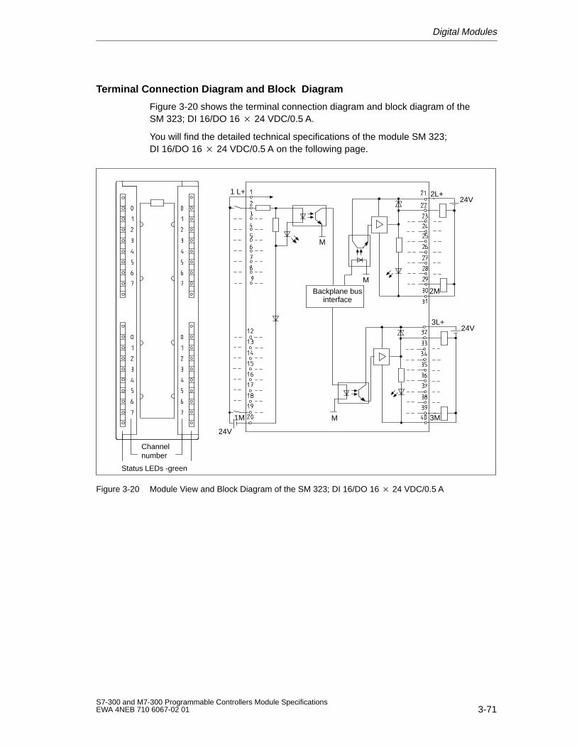
Digital Modules
3-71S7-300 and M7-300 Programmable Controllers Module SpecificationsEWA 4NEB 710 6067-02 01
Terminal Connection Diagram and Block Diagram
Figure 3-20 shows the terminal connection diagram and block diagram of theSM 323; DI 16/DO 16 24 VDC/0.5 A.
You will find the detailed technical specifications of the module SM 323;DI 16/DO 16 24 VDC/0.5 A on the following page.
Channelnumber
Status LEDs -green
1 L+
Backplane businterface
24V
1M
M
M
2L+
M
2M
3M
24V
24V3L+
Figure 3-20 Module View and Block Diagram of the SM 323; DI 16/DO 16 24 VDC/0.5 A
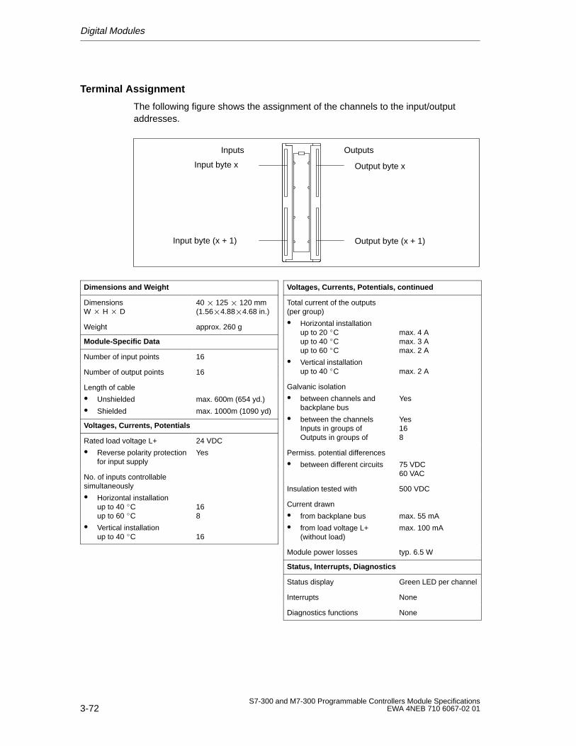
Digital Modules
3-72S7-300 and M7-300 Programmable Controllers Module Specifications
EWA 4NEB 710 6067-02 01
Terminal Assignment
The following figure shows the assignment of the channels to the input/outputaddresses.
Input byte x
Input byte (x + 1)
Inputs Outputs
Output byte x
Output byte (x + 1)
Dimensions and Weight
Dimensions W H D
40 125 120 mm(1.564.884.68 in.)
Weight approx. 260 g
Module-Specific Data
Number of input points 16
Number of output points 16
Length of cable
Unshielded
Shielded
max. 600m (654 yd.)
max. 1000m (1090 yd)
Voltages, Currents, Potentials
Rated load voltage L+
Reverse polarity protectionfor input supply
24 VDC
Yes
No. of inputs controllable simultaneously
Horizontal installationup to 40 Cup to 60 C
Vertical installationup to 40 C
168
16
Voltages, Currents, Potentials, continued
Total current of the outputs(per group)
Horizontal installationup to 20 Cup to 40 Cup to 60 C
Vertical installationup to 40 C
max. 4 Amax. 3 Amax. 2 A
max. 2 A
Galvanic isolation
between channels andbackplane bus
between the channelsInputs in groups ofOutputs in groups of
Yes
Yes168
Permiss. potential differences
between different circuits 75 VDC60 VAC
Insulation tested with 500 VDC
Current drawn
from backplane bus
from load voltage L+(without load)
max. 55 mA
max. 100 mA
Module power losses typ. 6.5 W
Status, Interrupts, Diagnostics
Status display Green LED per channel
Interrupts None
Diagnostics functions None
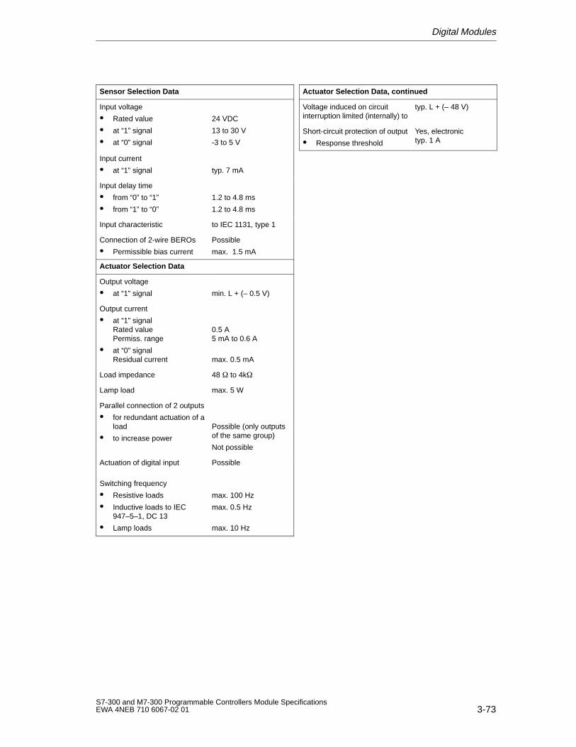
Digital Modules
3-73S7-300 and M7-300 Programmable Controllers Module SpecificationsEWA 4NEB 710 6067-02 01
Sensor Selection Data
Input voltage
Rated value
at “1” signal
at “0” signal
24 VDC
13 to 30 V
-3 to 5 V
Input current
at “1” signal typ. 7 mA
Input delay time
from “0” to “1”
from “1” to “0”
1.2 to 4.8 ms
1.2 to 4.8 ms
Input characteristic to IEC 1131, type 1
Connection of 2-wire BEROs
Permissible bias current
Possible
max. 1.5 mA
Actuator Selection Data
Output voltage
at “1” signal min. L + (– 0.5 V)
Output current
at “1” signalRated valuePermiss. range
at “0” signalResidual current
0.5 A5 mA to 0.6 A
max. 0.5 mA
Load impedance 48 to 4k
Lamp load max. 5 W
Parallel connection of 2 outputs
for redundant actuation of aload
to increase power
Possible (only outputsof the same group)
Not possible
Actuation of digital input
Switching frequency
Resistive loads
Inductive loads to IEC947–5–1, DC 13
Lamp loads
Possible
max. 100 Hz
max. 0.5 Hz
max. 10 Hz
Actuator Selection Data, continued
Voltage induced on circuitinterruption limited (internally) to
typ. L + (– 48 V)
Short-circuit protection of output
Response threshold
Yes, electronictyp. 1 A
Digital Modules
3-74S7-300 and M7-300 Programmable Controllers Module Specifications
EWA 4NEB 710 6067-02 01
3.4.2 Digital Input/Output Module SM 323; DI 8/DO 8 24 VDC/0.5 A
Order No.
6ES7 323-1BH00-0AA0
Characteristics
The digital input/output module SM 323; DI 8/DO 8 24 VDC/0.5 A has thefollowing salient features:
8 output points, isolated in groups of 8
8 input points, isolated in groups of 8
Rated input voltage 24 VDC
Rated load voltage 24 VDC
Outputs suitable for switches and 2/3/4-wire proximity switches (BEROs).
Inputs suitable for solenoid valves, DC contactors and indicator lights
Special Feature
When the power supply is switched on via a mechanical contact, the digital outputmodule SM 323; DI 8/DO 8 24 VDC/0.5 A sends a “1” signal to its outputs forapproximately 50 s. You must observe this when using the digital output moduleSM 323; DI 8/DO 8 24 VDC/0.5 A for high-speed counters!
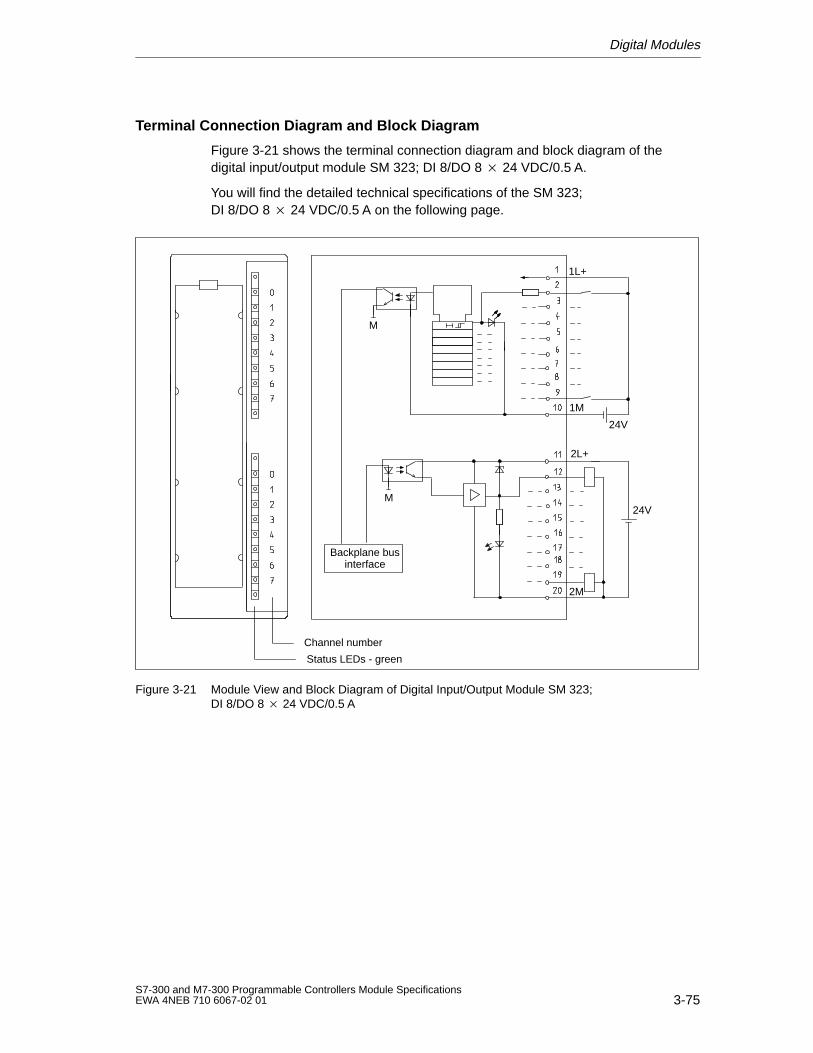
Digital Modules
3-75S7-300 and M7-300 Programmable Controllers Module SpecificationsEWA 4NEB 710 6067-02 01
Terminal Connection Diagram and Block Diagram
Figure 3-21 shows the terminal connection diagram and block diagram of thedigital input/output module SM 323; DI 8/DO 8 24 VDC/0.5 A.
You will find the detailed technical specifications of the SM 323; DI 8/DO 8 24 VDC/0.5 A on the following page.
Status LEDs - green
Channel number
Backplane businterface
1M
2M
24V
1L+
24V
2L+
M
M
Figure 3-21 Module View and Block Diagram of Digital Input/Output Module SM 323;DI 8/DO 8 24 VDC/0.5 A
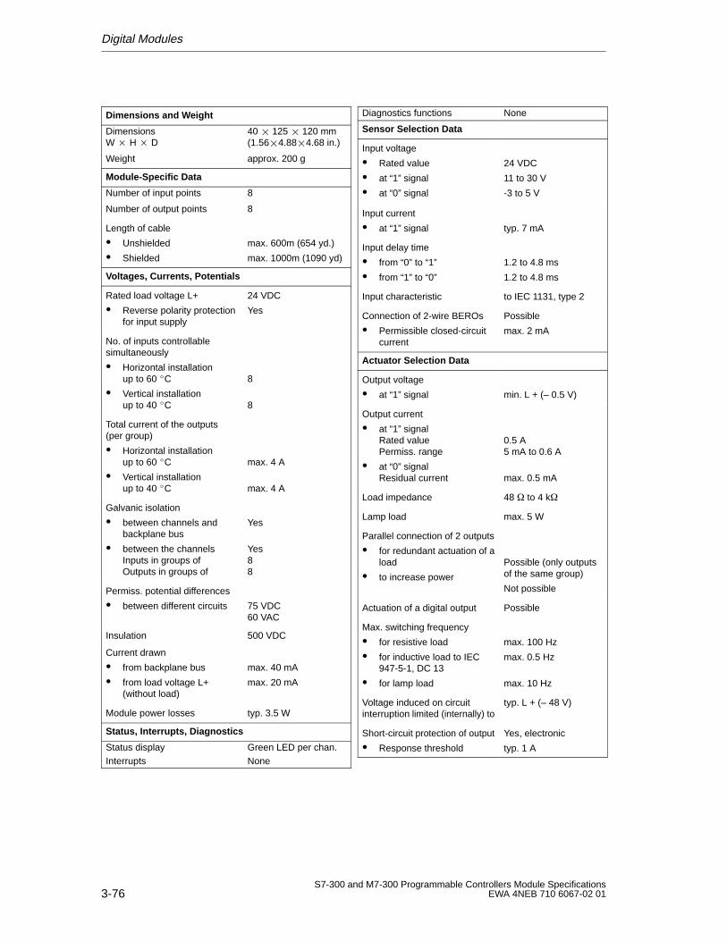
Digital Modules
3-76S7-300 and M7-300 Programmable Controllers Module Specifications
EWA 4NEB 710 6067-02 01
Dimensions and W eight
Dimensions W H D
40 125 120 mm(1.564.884.68 in.)
Weight approx. 200 g
Module-Specific Data
Number of input points 8
Number of output points 8
Length of cable
Unshielded
Shielded
max. 600m (654 yd.)
max. 1000m (1090 yd)
Voltages, Currents, Potentials
Rated load voltage L+
Reverse polarity protectionfor input supply
24 VDC
Yes
No. of inputs controllable simultaneously
Horizontal installationup to 60 C
Vertical installationup to 40 C
8
8
Total current of the outputs(per group)
Horizontal installationup to 60 C
Vertical installationup to 40 C
max. 4 A
max. 4 A
Galvanic isolation
between channels andbackplane bus
between the channelsInputs in groups ofOutputs in groups of
Yes
Yes88
Permiss. potential differences
between different circuits 75 VDC60 VAC
Insulation 500 VDC
Current drawn
from backplane bus
from load voltage L+(without load)
max. 40 mA
max. 20 mA
Module power losses typ. 3.5 W
Status, Interrupts, Diagnostics
Status display Green LED per chan.Interrupts None
Diagnostics functions None
Sensor Selection Data
Input voltage
Rated value
at “1” signal
at “0” signal
24 VDC
11 to 30 V
-3 to 5 V
Input current
at “1” signal typ. 7 mA
Input delay time
from “0” to “1”
from “1” to “0”
1.2 to 4.8 ms
1.2 to 4.8 ms
Input characteristic to IEC 1131, type 2
Connection of 2-wire BEROs
Permissible closed-circuitcurrent
Possible
max. 2 mA
Actuator Selection Data
Output voltage
at “1” signal min. L + (– 0.5 V)
Output current
at “1” signalRated valuePermiss. range
at “0” signalResidual current
0.5 A5 mA to 0.6 A
max. 0.5 mA
Load impedance 48 to 4 k
Lamp load max. 5 W
Parallel connection of 2 outputs
for redundant actuation of aload
to increase power
Possible (only outputsof the same group)
Not possible
Actuation of a digital output Possible
Max. switching frequency
for resistive load
for inductive load to IEC947-5-1, DC 13
for lamp load
max. 100 Hz
max. 0.5 Hz
max. 10 Hz
Voltage induced on circuitinterruption limited (internally) to
typ. L + (– 48 V)
Short-circuit protection of output
Response threshold
Yes, electronic
typ. 1 A
4-1S7-300 and M7-300 Programmable Controllers Module SpecificationsEWA 4NEB 710 6067-02 01
Analog Modules
Introduction
The S7-300 system has a number of analog modules for connecting to sensorsand/or loads/actuators.
Contents
In this chapter we describe the basic principles of analog technology and theanalog modules of the S7-300:
Section Contents Page
4.1 Analog Value Representation 4-2
4.2 Connecting Sensors/Transducers and Loads/Actuators to AnalogModules
4-18
4.3 Fundamental Principles for the Use of Analog Modules 4-38
4.4 Analog Input Module SM 331; AI 8 12 Bit 4-59
4.6 Analog Input Module SM 331; AI 2 12 Bit 4-79
4.7 Analog Output Module SM 332; AO 4 12 Bit 4-90
4.8 Analog Output Module SM 332; AO 2 12 Bit 4-96
4.9 Analog Output Module SM 332; AO 4 16 Bit 4-103
4.10 Analog Input/Output Module SM 334; AI 4/AO 2 8/8 Bit 4-109
4.11 Analog Input/Output Module SM 334; AI 4/AO 212 Bit 4-115
4
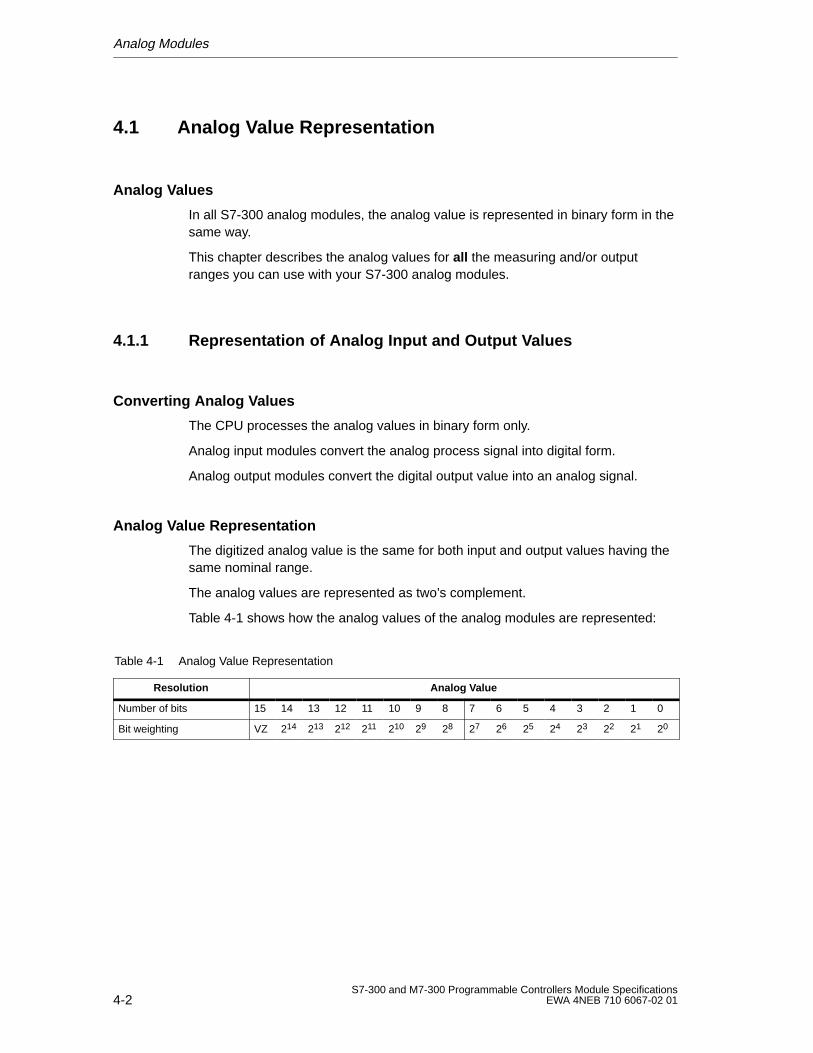
Analog Modules
4-2S7-300 and M7-300 Programmable Controllers Module Specifications
EWA 4NEB 710 6067-02 01
4.1 Analog V alue Representation
Analog Values
In all S7-300 analog modules, the analog value is represented in binary form in thesame way.
This chapter describes the analog values for all the measuring and/or outputranges you can use with your S7-300 analog modules.
4.1.1 Representation of Analog Input and Output Values
Converting Analog Values
The CPU processes the analog values in binary form only.
Analog input modules convert the analog process signal into digital form.
Analog output modules convert the digital output value into an analog signal.
Analog Value Representation
The digitized analog value is the same for both input and output values having thesame nominal range.
The analog values are represented as two’s complement.
Table 4-1 shows how the analog values of the analog modules are represented:
Table 4-1 Analog Value Representation
Resolution Analog Value
Number of bits 15 14 13 12 11 10 9 8 7 6 5 4 3 2 1 0
Bit weighting VZ 214 213 212 211 210 29 28 27 26 25 24 23 22 21 20
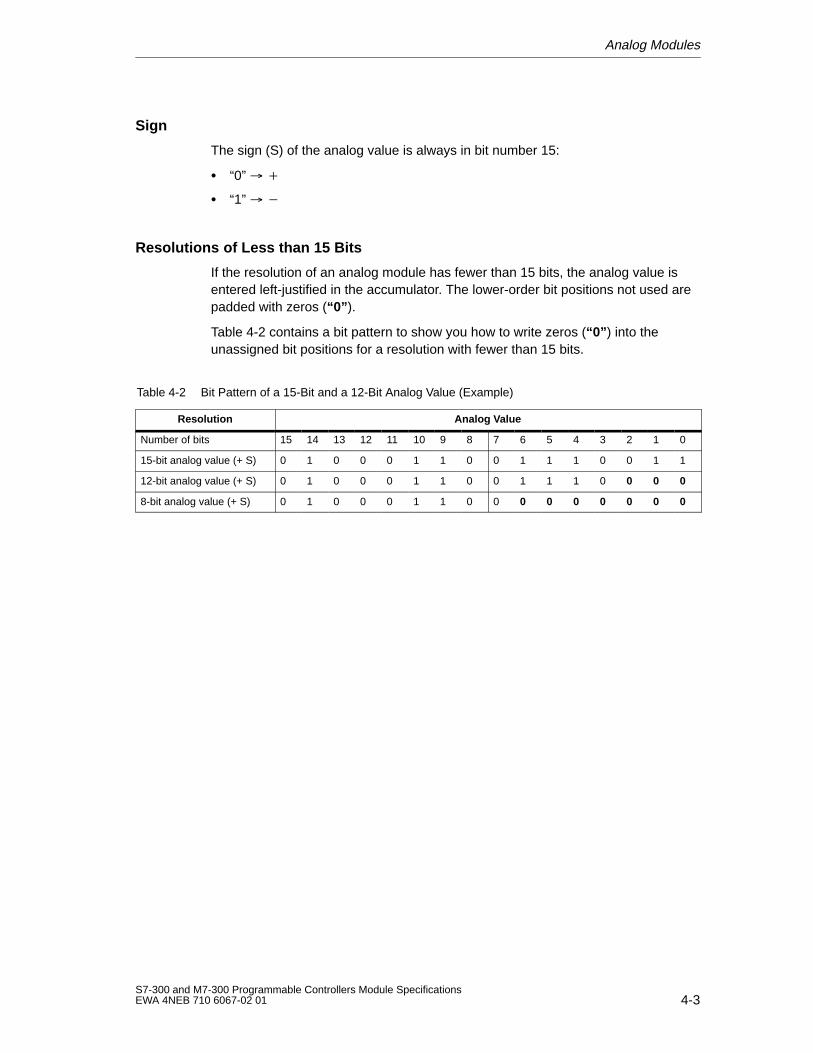
Analog Modules
4-3S7-300 and M7-300 Programmable Controllers Module SpecificationsEWA 4NEB 710 6067-02 01
Sign
The sign (S) of the analog value is always in bit number 15:
“0”
“1”
Resolutions of Less than 15 Bits
If the resolution of an analog module has fewer than 15 bits, the analog value isentered left-justified in the accumulator. The lower-order bit positions not used arepadded with zeros (“0” ).
Table 4-2 contains a bit pattern to show you how to write zeros (“0” ) into theunassigned bit positions for a resolution with fewer than 15 bits.
Table 4-2 Bit Pattern of a 15-Bit and a 12-Bit Analog Value (Example)
Resolution Analog Value
Number of bits 15 14 13 12 11 10 9 8 7 6 5 4 3 2 1 0
15-bit analog value (+ S) 0 1 0 0 0 1 1 0 0 1 1 1 0 0 1 1
12-bit analog value (+ S) 0 1 0 0 0 1 1 0 0 1 1 1 0 0 0 0
8-bit analog value (+ S) 0 1 0 0 0 1 1 0 0 0 0 0 0 0 0 0
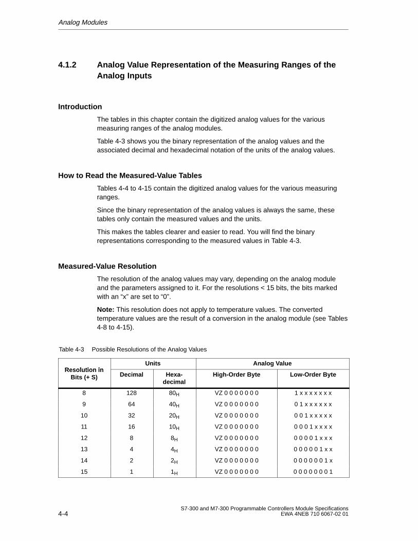
Analog Modules
4-4S7-300 and M7-300 Programmable Controllers Module Specifications
EWA 4NEB 710 6067-02 01
4.1.2 Analog Value Representation of the Measuring Ranges of theAnalog Inputs
Introduction
The tables in this chapter contain the digitized analog values for the variousmeasuring ranges of the analog modules.
Table 4-3 shows you the binary representation of the analog values and theassociated decimal and hexadecimal notation of the units of the analog values.
How to Read the Measured-Value Tables
Tables 4-4 to 4-15 contain the digitized analog values for the various measuringranges.
Since the binary representation of the analog values is always the same, thesetables only contain the measured values and the units.
This makes the tables clearer and easier to read. You will find the binaryrepresentations corresponding to the measured values in Table 4-3.
Measured-Value Resolution
The resolution of the analog values may vary, depending on the analog moduleand the parameters assigned to it. For the resolutions < 15 bits, the bits markedwith an “x” are set to “0”.
Note: This resolution does not apply to temperature values. The convertedtemperature values are the result of a conversion in the analog module (see Tables4-8 to 4-15).
Table 4-3 Possible Resolutions of the Analog Values
Resolution inUnits Analog V alue
Resolution inBits (+ S) Decimal Hexa-
decimalHigh-Order Byte Low-Order Byte
8 128 80H VZ 0 0 0 0 0 0 0 1 x x x x x x x
9 64 40H VZ 0 0 0 0 0 0 0 0 1 x x x x x x
10 32 20H VZ 0 0 0 0 0 0 0 0 0 1 x x x x x
11 16 10H VZ 0 0 0 0 0 0 0 0 0 0 1 x x x x
12 8 8H VZ 0 0 0 0 0 0 0 0 0 0 0 1 x x x
13 4 4H VZ 0 0 0 0 0 0 0 0 0 0 0 0 1 x x
14 2 2H VZ 0 0 0 0 0 0 0 0 0 0 0 0 0 1 x
15 1 1H VZ 0 0 0 0 0 0 0 0 0 0 0 0 0 0 1
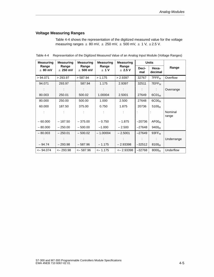
Analog Modules
4-5S7-300 and M7-300 Programmable Controllers Module SpecificationsEWA 4NEB 710 6067-02 01
Voltage Measuring Ranges
Table 4-4 shows the representation of the digitized measured value for the voltagemeasuring ranges 80 mV, 250 mV, 500 mV, 1 V, 2.5 V.
Table 4-4 Representation of the Digitized Measured Value of an Analog Input Module (Voltage Ranges)
MeasuringRange
MeasuringRange
MeasuringRange
MeasuringRange
MeasuringRange
UnitsgRange 80 mV
gRange 250 mV
gRange 500 mV
gRange 1 V
gRange 2.5 V Deci-
malHexa-
decimalRange
> 94.071 > 293.97 > 587.94 > 1.175 > 2.9397 32767 7FFFH Overflow
94.071 293.97 587.94 1.175 2.9397 32511 7EFFH
: : : : : : : Overrange
80.003 250.01 500.02 1.00004 2.5001 27649 6C01H
g
80.000 250.00 500.00 1.000 2.500 27648 6C00H
60.000 187.50 375.00 0.750 1.875 20736 5100H
: : : : : : : Nominalrange
– 60.000 – 187.50 – 375.00 – 0.750 – 1.875 –20736 AF00H
– 80.000 – 250.00 – 500.00 –1.000 – 2.500 –27648 9400H
– 80.003 – 250.01 – 500.02 – 1.00004 – 2.5001 –27649 93FFH
: : : : : : : Underrange
– 94.74 – 293.98 – 587.96 – 1.175 – 2.93398 –32512 8100H
g
<– 94.074 <– 293.98 <– 587.96 <– 1.175 <– 2.93398 –32768 8000H Underflow
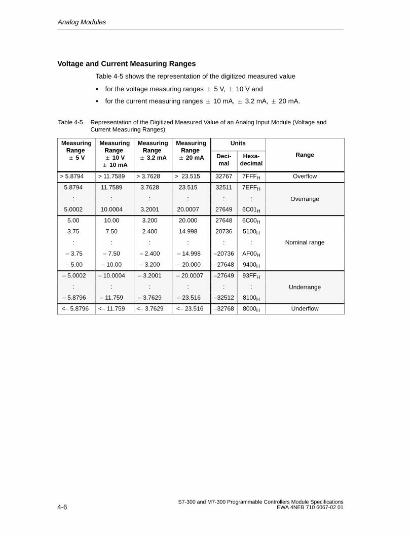
Analog Modules
4-6S7-300 and M7-300 Programmable Controllers Module Specifications
EWA 4NEB 710 6067-02 01
Voltage and Current Measuring Ranges
Table 4-5 shows the representation of the digitized measured value
for the voltage measuring ranges 5 V, 10 V and
for the current measuring ranges 10 mA, 3.2 mA, 20 mA.
Table 4-5 Representation of the Digitized Measured Value of an Analog Input Module (Voltage andCurrent Measuring Ranges)
MeasuringRange
MeasuringRange
MeasuringRange
MeasuringRange
UnitsRange 5 V
Range 10 V 10 mA
Range 3.2 mA
Range 20 mA Deci-
malHexa-
decimalRange
> 5.8794 > 11.7589 > 3.7628 > 23.515 32767 7FFFH Overflow
5.8794 11.7589 3.7628 23.515 32511 7EFFH
: : : : : : Overrange
5.0002 10.0004 3.2001 20.0007 27649 6C01H
g
5.00 10.00 3.200 20.000 27648 6C00H
3.75 7.50 2.400 14.998 20736 5100H
: : : : : : Nominal range
– 3.75 – 7.50 – 2.400 – 14.998 –20736 AF00H
– 5.00 – 10.00 – 3.200 – 20.000 –27648 9400H
– 5.0002 – 10.0004 – 3.2001 – 20.0007 –27649 93FFH
: : : : : : Underrange
– 5.8796 – 11.759 – 3.7629 – 23.516 –32512 8100H
g
<– 5.8796 <– 11.759 <– 3.7629 <– 23.516 –32768 8000H Underflow
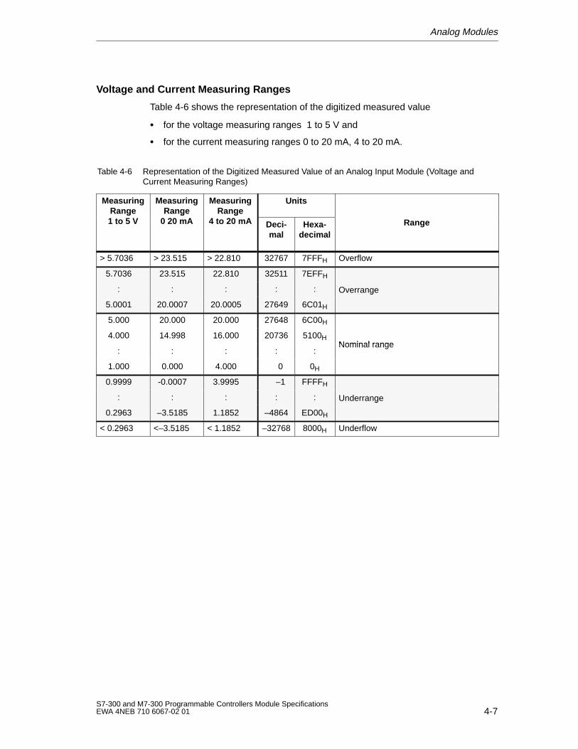
Analog Modules
4-7S7-300 and M7-300 Programmable Controllers Module SpecificationsEWA 4NEB 710 6067-02 01
Voltage and Current Measuring Ranges
Table 4-6 shows the representation of the digitized measured value
for the voltage measuring ranges 1 to 5 V and
for the current measuring ranges 0 to 20 mA, 4 to 20 mA.
Table 4-6 Representation of the Digitized Measured Value of an Analog Input Module (Voltage andCurrent Measuring Ranges)
MeasuringRange1 5 V
MeasuringRange
0 20 A
MeasuringRange
4 20 A
UnitsRange1 to 5 V
Range0 20 mA
Range4 to 20 mA Deci-
malHexa-
decimalRange
> 5.7036 > 23.515 > 22.810 32767 7FFFH Overflow
5.7036 23.515 22.810 32511 7EFFH
: : : : : Overrange
5.0001 20.0007 20.0005 27649 6C01H
g
5.000 20.000 20.000 27648 6C00H
4.000 14.998 16.000 20736 5100HNominal range
: : : : :Nominal range
1.000 0.000 4.000 0 0H
0.9999 -0.0007 3.9995 –1 FFFFH
: : : : : Underrange
0.2963 –3.5185 1.1852 –4864 ED00H
g
< 0.2963 <–3.5185 < 1.1852 –32768 8000H Underflow
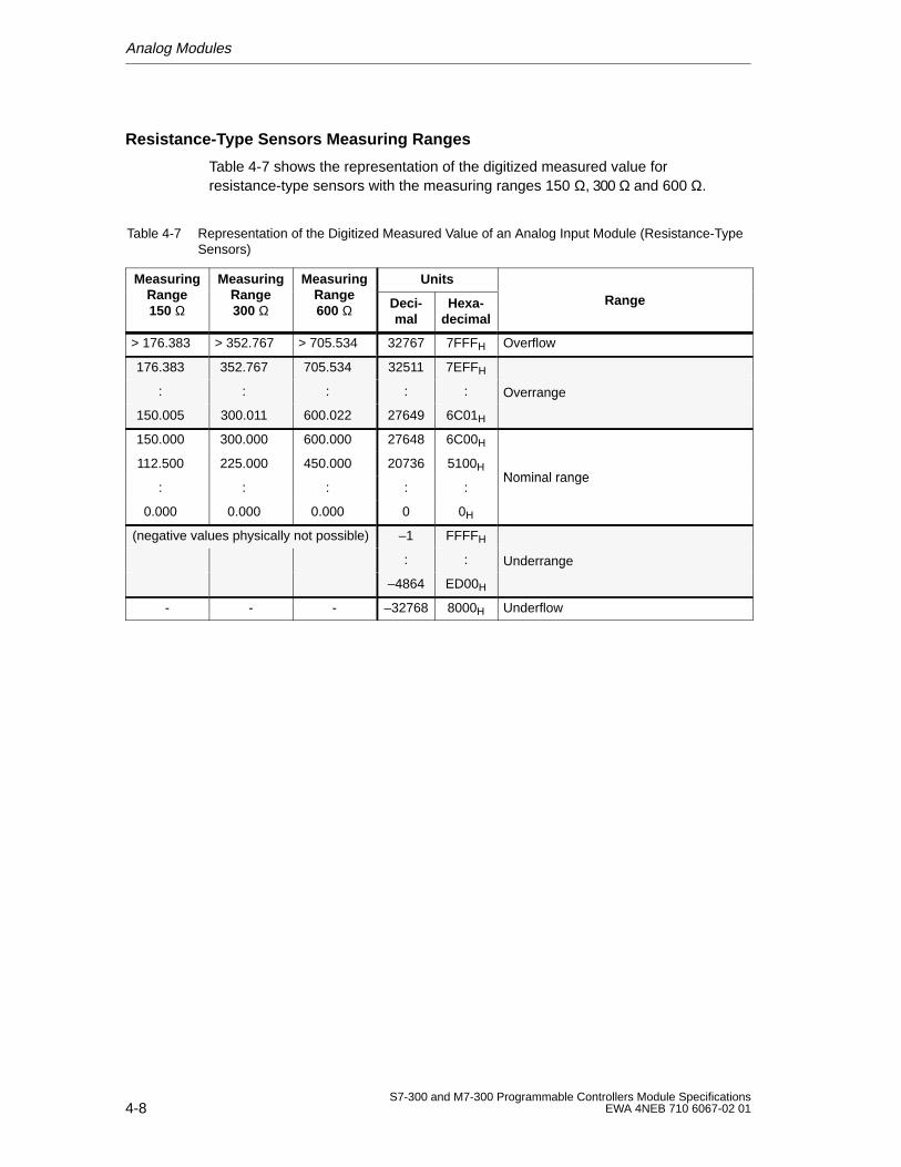
Analog Modules
4-8S7-300 and M7-300 Programmable Controllers Module Specifications
EWA 4NEB 710 6067-02 01
Resistance-Type Sensors Measuring Ranges
Table 4-7 shows the representation of the digitized measured value forresistance-type sensors with the measuring ranges 150 Ω, 300 Ω and 600 Ω.
Table 4-7 Representation of the Digitized Measured Value of an Analog Input Module (Resistance-TypeSensors)
MeasuringRange
MeasuringRange
MeasuringRange
UnitsgRange150 Ω
gRange300 Ω
gRange600 Ω Deci-
malHexa-
decimalRange
> 176.383 > 352.767 > 705.534 32767 7FFFH Overflow
176.383 352.767 705.534 32511 7EFFH
: : : : : Overrange
150.005 300.011 600.022 27649 6C01H
g
150.000 300.000 600.000 27648 6C00H
112.500 225.000 450.000 20736 5100HNominal range
: : : : :Nominal range
0.000 0.000 0.000 0 0H
(negative values physically not possible) –1 FFFFH
: : Underrange
–4864 ED00H
g
- - - –32768 8000H Underflow

Analog Modules
4-9S7-300 and M7-300 Programmable Controllers Module SpecificationsEWA 4NEB 710 6067-02 01
Standard Temperature Range Pt 100
Table 4-8 shows the representation of the digitized measured value for thestandard temperature range of the Pt 100 sensor.
Table 4-8 Representation of the Digitized Measured Value of an Analog Input Module(Standard Temperature Range, Pt 100)
Standard Temperature
Units RangeTemperatureRange Pt 100
850 CDecimal Hexa-
decimal
> 1000.0 32767 7FFFH Overflow
1000.0
:
850.1
10000
:
8501
2710H
:
2135H
Overrange
850.0
:
–200.0
8500
:
–2000
2134H
:
F830H
Nominal range
–200.1
:
–243.0
–2001
:
–2430
F82FH
:
F682H
Underrange
<– 243.0 –32768 8000H Underflow
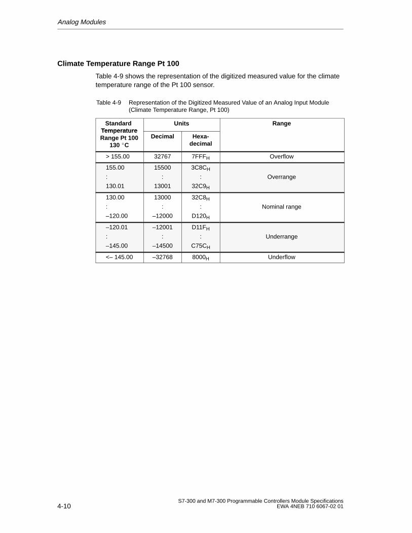
Analog Modules
4-10S7-300 and M7-300 Programmable Controllers Module Specifications
EWA 4NEB 710 6067-02 01
Climate Temperature Range Pt 100
Table 4-9 shows the representation of the digitized measured value for the climatetemperature range of the Pt 100 sensor.
Table 4-9 Representation of the Digitized Measured Value of an Analog Input Module(Climate Temperature Range, Pt 100)
Standard Temperature
Units RangeTemperatureRange Pt 100
130 CDecimal Hexa-
decimal
> 155.00 32767 7FFFH Overflow
155.00
:
130.01
15500
:
13001
3C8CH
:
32C9H
Overrange
130.00
:
–120.00
13000
:
–12000
32C8H
:
D120H
Nominal range
–120.01
:
–145.00
–12001
:
–14500
D11FH
:
C75CH
Underrange
<– 145.00 –32768 8000H Underflow
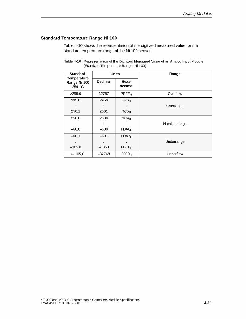
Analog Modules
4-11S7-300 and M7-300 Programmable Controllers Module SpecificationsEWA 4NEB 710 6067-02 01
Standard Temperature Range Ni 100
Table 4-10 shows the representation of the digitized measured value for thestandard temperature range of the Ni 100 sensor.
Table 4-10 Representation of the Digitized Measured Value of an Analog Input Module(Standard Temperature Range, Ni 100)
Standard Temperature
Units RangeTemperatureRange Ni 100
250 CDecimal Hexa-
decimal
>295.0 32767 7FFFH Overflow
295.0
:
250.1
2950
:
2501
B86H
:
9C5H
Overrange
250.0
:
–60.0
2500
:
–600
9C4H
:
FDA8H
Nominal range
–60.1
:
–105.0
–601
:
–1050
FDA7H
:
FBE6H
Underrange
<– 105,0 –32768 8000H Underflow
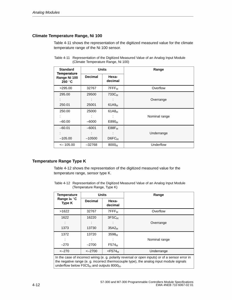
Analog Modules
4-12S7-300 and M7-300 Programmable Controllers Module Specifications
EWA 4NEB 710 6067-02 01
Climate Temperature Range, Ni 100
Table 4-11 shows the representation of the digitized measured value for the climatetemperature range of the Ni 100 sensor.
Table 4-11 Representation of the Digitized Measured Value of an Analog Input Module(Climate Temperature Range, Ni 100)
Standard Temperature
Units RangeTemperatureRange Ni 100
250 CDecimal Hexa-
decimal
>295.00 32767 7FFFH Overflow
295.00
:
250.01
29500
:
25001
733CH
:
61A9H
Overrange
250.00
:
–60.00
25000
:
–6000
61A8H
:
E890H
Nominal range
–60.01
:
–105.00
–6001
:
–10500
E88FH
:
D6FCH
Underrange
<– 105.00 –32768 8000H Underflow
Temperature Range Type K
Table 4-12 shows the representation of the digitized measured value for thetemperature range, sensor type K.
Table 4-12 Representation of the Digitized Measured Value of an Analog Input Module(Temperature Range, Type K)
TemperatureRange i n C
Units RangepRange i n C
Type K Decimal Hexa-decimal
g
>1622 32767 7FFFH Overflow
1622
:
1373
16220
:
13730
3FSCH
:
35A2H
Overrange
1372
:
–270
13720
:
–2700
3598H
:
F574H
Nominal range
<–270 <–2700 <F574H Underrange
In the case of incorrect wiring (e. g. polarity reversal or open inputs) or of a sensor error inthe negative range (e. g. incorrect thermocouple type), the analog input module signalsunderflow below F0C5H and outputs 8000H.
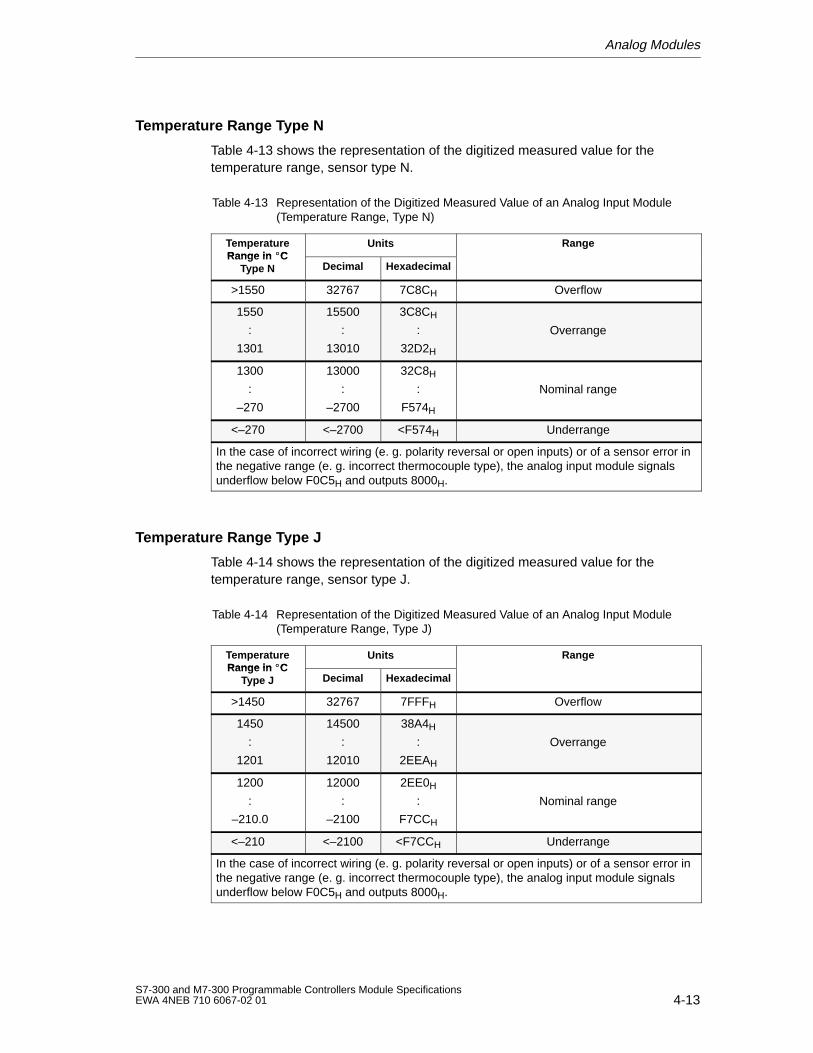
Analog Modules
4-13S7-300 and M7-300 Programmable Controllers Module SpecificationsEWA 4NEB 710 6067-02 01
Temperature Range Type N
Table 4-13 shows the representation of the digitized measured value for thetemperature range, sensor type N.
Table 4-13 Representation of the Digitized Measured Value of an Analog Input Module(Temperature Range, Type N)
TemperatureRange in C
Units RangeRange in C
Type N Decimal Hexadecimal
>1550 32767 7C8CH Overflow
1550
:
1301
15500
:
13010
3C8CH
:
32D2H
Overrange
1300
:
–270
13000
:
–2700
32C8H
:
F574H
Nominal range
<–270 <–2700 <F574H Underrange
In the case of incorrect wiring (e. g. polarity reversal or open inputs) or of a sensor error inthe negative range (e. g. incorrect thermocouple type), the analog input module signalsunderflow below F0C5H and outputs 8000H.
Temperature Range Type J
Table 4-14 shows the representation of the digitized measured value for thetemperature range, sensor type J.
Table 4-14 Representation of the Digitized Measured Value of an Analog Input Module(Temperature Range, Type J)
TemperatureRange in C
Units RangeRange in C
Type J Decimal Hexadecimal
>1450 32767 7FFFH Overflow
1450
:
1201
14500
:
12010
38A4H
:
2EEAH
Overrange
1200
:
–210.0
12000
:
–2100
2EE0H
:
F7CCH
Nominal range
<–210 <–2100 <F7CCH Underrange
In the case of incorrect wiring (e. g. polarity reversal or open inputs) or of a sensor error inthe negative range (e. g. incorrect thermocouple type), the analog input module signalsunderflow below F0C5H and outputs 8000H.
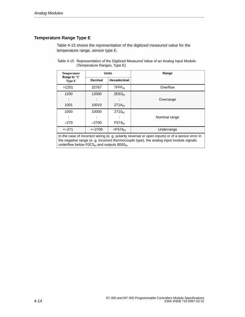
Analog Modules
4-14S7-300 and M7-300 Programmable Controllers Module Specifications
EWA 4NEB 710 6067-02 01
Temperature Range Type E
Table 4-15 shows the representation of the digitized measured value for thetemperature range, sensor type E.
Table 4-15 Representation of the Digitized Measured Value of an Analog Input Module(Temperature Ranges, Type E)
TemperatureRangein C
Units RangeRange in C
Type E Decimal Hexadecimal
>1201 32767 7FFFH Overflow
1200
:
1001
12000
:
10010
2EE0H
:
271AH
Overrange
1000
:
–270
10000
:
–2700
2710H
:
F574H
Nominal range
<–271 <–2700 <F574H Underrange
In the case of incorrect wiring (e. g. polarity reversal or open inputs) or of a sensor error inthe negative range (e. g. incorrect thermocouple type), the analog input module signalsunderflow below F0C5H and outputs 8000H.
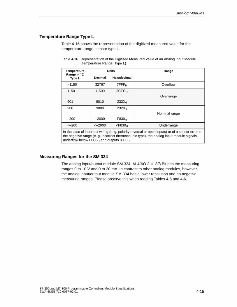
Analog Modules
4-15S7-300 and M7-300 Programmable Controllers Module SpecificationsEWA 4NEB 710 6067-02 01
Temperature Range Type L
Table 4-16 shows the representation of the digitized measured value for thetemperature range, sensor type L.
Table 4-16 Representation of the Digitized Measured Value of an Analog Input Module(Temperature Range, Type L)
TemperatureRange in C
Units RangeRange in C
Type L Decimal Hexadecimal
>1150 32767 7FFFH Overflow
1150
:
901
11500
:
9010
2CECH
:
2332H
Overrange
900
:
–200
9000
:
–2000
2328H
:
F830H
Nominal range
<–200 <–2000 <F830H Underrange
In the case of incorrect wiring (e. g. polarity reversal or open inputs) or of a sensor error inthe negative range (e. g. incorrect thermocouple type), the analog input module signalsunderflow below F0C5H and outputs 8000H.
Measuring Ranges for the SM 334
The analog input/output module SM 334; AI 4/AO 2 8/8 Bit has the measuringranges 0 to 10 V and 0 to 20 mA. In contrast to other analog modules, however,the analog input/output module SM 334 has a lower resolution and no negativemeasuring ranges. Please observe this when reading Tables 4-5 and 4-6.
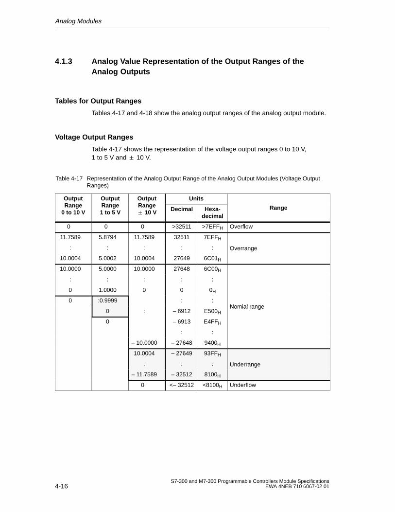
Analog Modules
4-16S7-300 and M7-300 Programmable Controllers Module Specifications
EWA 4NEB 710 6067-02 01
4.1.3 Analog Value Representation of the Output Ranges of theAnalog Outputs
Tables for Output Ranges
Tables 4-17 and 4-18 show the analog output ranges of the analog output module.
Voltage Output Ranges
Table 4-17 shows the representation of the voltage output ranges 0 to 10 V,1 to 5 V and 10 V.
Table 4-17 Representation of the Analog Output Range of the Analog Output Modules (Voltage OutputRanges)
OutputRange
OutputRange
OutputRange
UnitspRange
0 to 10 V
pRange1 to 5 V
pRange 10 V Decimal Hexa-
decimalRange
0 0 0 >32511 >7EFFH Overflow
11.7589 5.8794 11.7589 32511 7EFFH
: : : : : Overrange
10.0004 5.0002 10.0004 27649 6C01H
g
10.0000 5.0000 10.0000 27648 6C00H
: : : : :
0 1.0000 0 0 0H
0 :0.9999 : :Nomial range
0 : – 6912 E500HNomial range
0 – 6913 E4FFH
: :
– 10.0000 – 27648 9400H
10.0004 – 27649 93FFH
: : : Underrange
– 11.7589 – 32512 8100H
g
0 <– 32512 <8100H Underflow
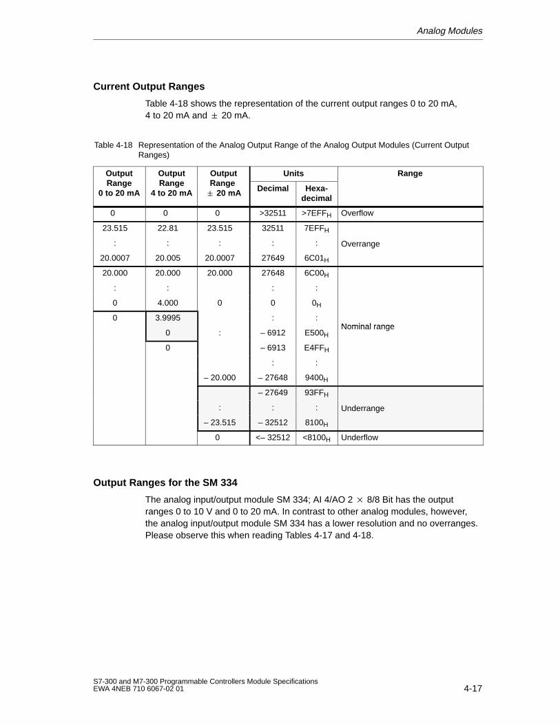
Analog Modules
4-17S7-300 and M7-300 Programmable Controllers Module SpecificationsEWA 4NEB 710 6067-02 01
Current Output Ranges
Table 4-18 shows the representation of the current output ranges 0 to 20 mA,4 to 20 mA and 20 mA.
Table 4-18 Representation of the Analog Output Range of the Analog Output Modules (Current OutputRanges)
OutputRange
OutputRange
OutputRange
Units RangepRange
0 to 20 mA
pRange
4 to 20 mA
pRange 20 mA Decimal Hexa-
decimal
0 0 0 >32511 >7EFFH Overflow
23.515 22.81 23.515 32511 7EFFH
: : : : : Overrange
20.0007 20.005 20.0007 27649 6C01H
g
20.000 20.000 20.000 27648 6C00H
: : : :
0 4.000 0 0 0H
0 3.9995 : :Nominal range
0 : – 6912 E500HNominal range
0 – 6913 E4FFH
: :
– 20.000 – 27648 9400H
– 27649 93FFH
: : : Underrange
– 23.515 – 32512 8100H
g
0 <– 32512 <8100H Underflow
Output Ranges for the SM 334
The analog input/output module SM 334; AI 4/AO 2 8/8 Bit has the outputranges 0 to 10 V and 0 to 20 mA. In contrast to other analog modules, however,the analog input/output module SM 334 has a lower resolution and no overranges.Please observe this when reading Tables 4-17 and 4-18.
Analog Modules
4-18S7-300 and M7-300 Programmable Controllers Module Specifications
EWA 4NEB 710 6067-02 01
4.2 Connecting Sensors/T ransducers and Loads/Actuatorsto Analog Modules
In this Chapter
In this chapter, you will find:
Fundamentals on how to connect sensors and transducers
A description of thermocouples
– Design and principle of operation of thermocouples
– Use of compensating boxes
A description of how to connect up thermocouples to analog inputs
A description of how to connect up other sensors and transducers to analoginputs
– Connection of voltage sensors
– Connection of resistance thermometers
– Connection of current sensors
– Connection of other sensors and transducers
A description of how to connect up loads/actuators to analog inputs
Analog Modules
4-19S7-300 and M7-300 Programmable Controllers Module SpecificationsEWA 4NEB 710 6067-02 01
4.2.1 Connecting Sensors/Transducers to Analog Inputs
Introduction
You can connect various types of transducers and sensors to your analog inputmodules:
Voltage sensors
Current sensors as
– 2-wire transducers
– 4-wire transducers
Resistors
This chapter tells you how to connect up your sensors and transducers and whatprecautions you have to take when doing so.
Cables for Analog Signals
To reduce electrical interference, you should use twisted-pair shielded cables forthe analog signals. The shield of the analog signal cables should be grounded atboth cable ends. If there are potential differences between the cable ends, anequipotential bonding current can flow over the shield, which leads to aninterference of the analog signals. In such a case, you should ground the shield atone end of the cable only.
Isolated Analog Input Modules
With the isolated analog input modules there is no electrical connection betweenthe reference point of the measuring circuit MANA and the M terminal of the CPU.
You must use isolated analog input modules if a potential difference UISO canoccur between the reference point of the measuring circuit MANA and theM terminal of the CPU. Make sure that UISO does not exceed the permissiblevalue. If it is possible that the permissible value is exceeded, establish aconnection between the MANA terminal and the M terminal of the CPU.
Non-Isolated Analog Input Modules
With the non-isolated analog input modules, you must establish a connectionbetween the reference point of the measuring circuit MANA and the M terminal ofthe CPU or IM 153. Therefore, connect the MANA terminal with the M terminal ofthe CPU or IM 153. A potential difference between MANA and the M terminal of theCPU or IM 153 can lead to a corruption of the analog signal.
Analog Modules
4-20S7-300 and M7-300 Programmable Controllers Module Specifications
EWA 4NEB 710 6067-02 01
Connection of Sensors to Analog Inputs
Only a limited potential difference UCM (common mode voltage) may occurbetween the measuring lines M– of the input channels and the reference point ofthe measuring circuit MANA. In order to prevent the permissible value from beingexceeded, you must take different actions, depending on the potential connectionof the sensors (isolated, non-isolated). These actions are described in this section.
When connecting resistance-type sensors or 2-wire transducers for currentmeasurement, you cannot make the connection from M– to MANA. This alsoapplies to inputs which are not used.
Abbreviations and Mnemonics
The abbreviations and mnemonics used in Figures 4-1 to 4-4 have the followingmeanings:
M +: Measuring lead (positive)
M –: Measuring lead (negative)
MANA: Reference potential of the analog measuring circuit
M: Ground terminal
L +: Terminal for 24 VDC supply voltage
UCM: Potential difference between inputs and reference potential of the MANA measuring circuit
UISO: Potential difference between MANA and M terminal of CPU
Analog Modules
4-21S7-300 and M7-300 Programmable Controllers Module SpecificationsEWA 4NEB 710 6067-02 01
Isolated Sensors
The isolated sensors are not connected with the local ground potential. They canbe operated free of potential. Caused by local conditions or interferences potentialdifferences UCM (static or dynamic) can occur between the measuring lines M– ofthe input channels and the reference point of the measuring circuit MANA.
In order to prevent the permissible value for UCM from being exceeded whenoperating in areas with heavy EMC interference, the following applies:
for analog input modules SM 331 with order no. 331-7K.00:Connect M– with MANA!
for analog input modules SM 331 with order no. 331-7K.01:We recommend you to connect M– with MANA.
Do not connect M– to MANA when connecting 2-wire measuring transducers forcurrent measurement and resistance-type sensors.
You can operate the CPU as follows:
Analog input module CPU
Isolated Non-floating (bridge between
floating (no bridge between
and M)
or
and M)
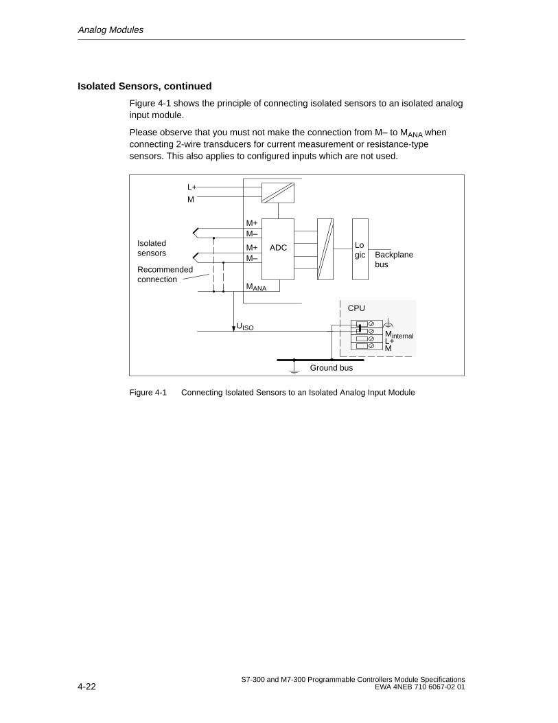
Analog Modules
4-22S7-300 and M7-300 Programmable Controllers Module Specifications
EWA 4NEB 710 6067-02 01
Isolated Sensors, continued
Figure 4-1 shows the principle of connecting isolated sensors to an isolated analoginput module.
Please observe that you must not make the connection from M– to MANA whenconnecting 2-wire transducers for current measurement or resistance-typesensors. This also applies to configured inputs which are not used.
Isolated sensors
M+
M
L+
M–
MANA
M+M– Backplane
bus
ADC
MinternalL+M
Ground bus
CPU
UISO
Logic
Recommended connection
Figure 4-1 Connecting Isolated Sensors to an Isolated Analog Input Module
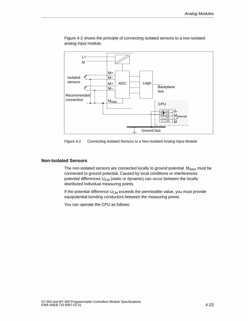
Analog Modules
4-23S7-300 and M7-300 Programmable Controllers Module SpecificationsEWA 4NEB 710 6067-02 01
Figure 4-2 shows the principle of connecting isolated sensors to a non-isolatedanalog input module.
Isolatedsensors
M+
M
L+
M–
MANA
M+M– Backplane
bus
MinternalL+M
Ground bus
CPU
ADC Logic
Recommendedconnection
Figure 4-2 Connecting Isolated Sensors to a Non-Isolated Analog Input Module
Non-Isolated Sensors
The non-isolated sensors are connected locally to ground potential. MANA must beconnected to ground potential. Caused by local conditions or interferencespotential differences UCM (static or dynamic) can occur between the locallydistributed individual measuring points.
If the potential difference UCM exceeds the permissible value, you must provideequipotential bonding conductors between the measuring points.
You can operate the CPU as follows:
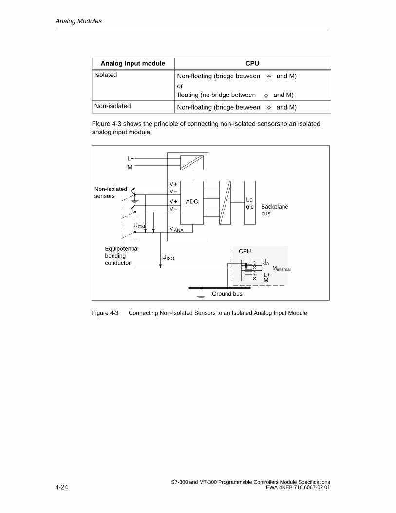
Analog Modules
4-24S7-300 and M7-300 Programmable Controllers Module Specifications
EWA 4NEB 710 6067-02 01
Analog Input module CPU
Isolated Non-floating (bridge between
floating (no bridge between
and M)
orand M)
Non-isolated Non-floating (bridge between and M)
Figure 4-3 shows the principle of connecting non-isolated sensors to an isolatedanalog input module.
Non-isolatedsensors
M+
M
L+
M–
MANA
M+M– Backplane
bus
UCM
ADC
MinternalL+M
Ground bus
CPUUISO
Logic
Equipotentialbondingconductor
Figure 4-3 Connecting Non-Isolated Sensors to an Isolated Analog Input Module
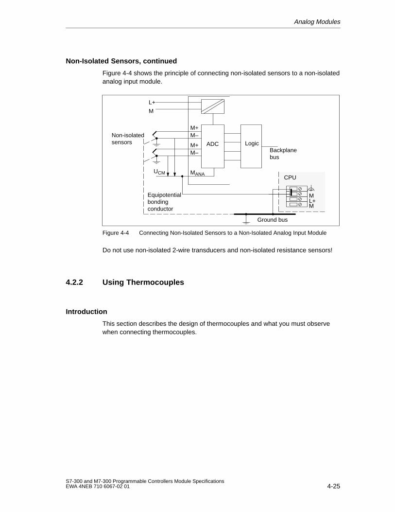
Analog Modules
4-25S7-300 and M7-300 Programmable Controllers Module SpecificationsEWA 4NEB 710 6067-02 01
Non-Isolated Sensors, continued
Figure 4-4 shows the principle of connecting non-isolated sensors to a non-isolatedanalog input module.
Non-isolatedsensors
M+
M
L+
M–
MANA
M+M– Backplane
bus
ML+M
Ground bus
CPU
ADC Logic
UCM
Equipotentialbondingconductor
Figure 4-4 Connecting Non-Isolated Sensors to a Non-Isolated Analog Input Module
Do not use non-isolated 2-wire transducers and non-isolated resistance sensors!
4.2.2 Using Thermocouples
Introduction
This section describes the design of thermocouples and what you must observewhen connecting thermocouples.
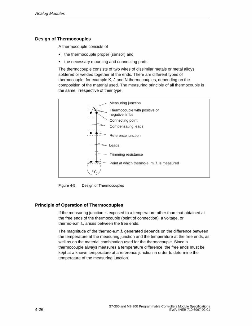
Analog Modules
4-26S7-300 and M7-300 Programmable Controllers Module Specifications
EWA 4NEB 710 6067-02 01
Design of Thermocouples
A thermocouple consists of
the thermocouple proper (sensor) and
the necessary mounting and connecting parts
The thermocouple consists of two wires of dissimilar metals or metal alloyssoldered or welded together at the ends. There are different types ofthermocouple, for example K, J and N thermocouples, depending on thecomposition of the material used. The measuring principle of all thermocouple isthe same, irrespective of their type.
° C
Trimming resistance
Leads
Compensating leads
Reference junction
Connecting point
Thermocouple with positive ornegative limbs
Measuring junction
Point at which thermo-e. m. f. is measured
Figure 4-5 Design of Thermocouples
Principle of Operation of Thermocouples
If the measuring junction is exposed to a temperature other than that obtained atthe free ends of the thermocouple (point of connection), a voltage, orthermo-e.m.f., arises between the free ends.
The magnitude of the thermo-e.m.f. generated depends on the difference betweenthe temperature at the measuring junction and the temperature at the free ends, aswell as on the material combination used for the thermocouple. Since athermocouple always measures a temperature difference, the free ends must bekept at a known temperature at a reference junction in order to determine thetemperature of the measuring junction.
Analog Modules
4-27S7-300 and M7-300 Programmable Controllers Module SpecificationsEWA 4NEB 710 6067-02 01
Extension to a Reference Junction
The thermocouples can be extended from their point of connection to a point ofknown temperature (reference junction) by means of compensating wires.
These compensating wires consist of the same material as the thermocouplewires. The supply leads are copper wire. You should use external compensation inthis case. Make sure these wires are connected with the correct polarity, otherwisethere will be considerable measurement errors.
External Compensation
You can compensate for the effects of temperature fluctuations at the referencejunction by means of compensating leads, for example by connecting acompensating box.
The compensating box contains a bridge circuit calibrated for a definite referencejunction temperature. The reference junction is formed by the connections for theends of the thermocouple’s compensating leads.
If the actual temperature deviates from the compensating temperature, thetemperature-sensitive bridge resistance changes. This results in a positive ornegative compensating voltage, which is added to the thermo-e.m.f.
Use compensating boxes with a reference junction temperature of 0 °C (32 °F)for analog input modules.
Please note the following:
The compensating box must have an isolated supply.
The power supply must have adequate filtering, for example by means of agrounded shielding winding.
Internal Compensation
Bei der internen Kompensation können Sie die Vergleichstelle an den Klemmender Analogeingabebaugruppe bilden. In diesem Fall müssen Sie dieAusgleichsleitungen bis zur Analogbaugruppe führen. Der interneTemperatursensor erfaßt die Temperatur der Baugruppe und liefert eineKompensationsspannung.
Note that internal compensation is not as accurate as external compensation!
Analog Modules
4-28S7-300 and M7-300 Programmable Controllers Module Specifications
EWA 4NEB 710 6067-02 01
Using Thermocouples
If you wish to connect thermocouples, you must observe the following:
You can use internal or external compensation, depending on where you want thereference junction to be.
If you employ internal compensation, the internal temperature of the module isused for comparison purposes.
If you employ external compensation, the temperature of the reference junction ofthe thermocouples is taken into account via a compensating box.
Connect the compensating box to the COMP terminals of the module, locating thecompensating box at the reference junction of the thermocouples.
The following constraints apply:
The parameters of a channel group have general validity for all channels of thatgroup (for example, input voltage, integrating time etc.)
External compensation with the compensating box connected to the COMPterminals of the module can only be implemented for one type of thermocouple.That is, you must use the same type of thermocouple for all channels that areconnected to that compensating box.
Abbreviations and Mnemonics
The abbreviations and mnemonics used in Figures 4-6 and 4-7 have the followingmeanings:
M +: Measuring lead (positive)
M –: Measuring lead (negative)
COMP+: Compensating terminal (positive)
COMP –: Compensating terminal (negative)
MANA: Reference potential of the analog measuring circuit
M : Ground terminal
L +: Terminal for 24 VDC supply voltage
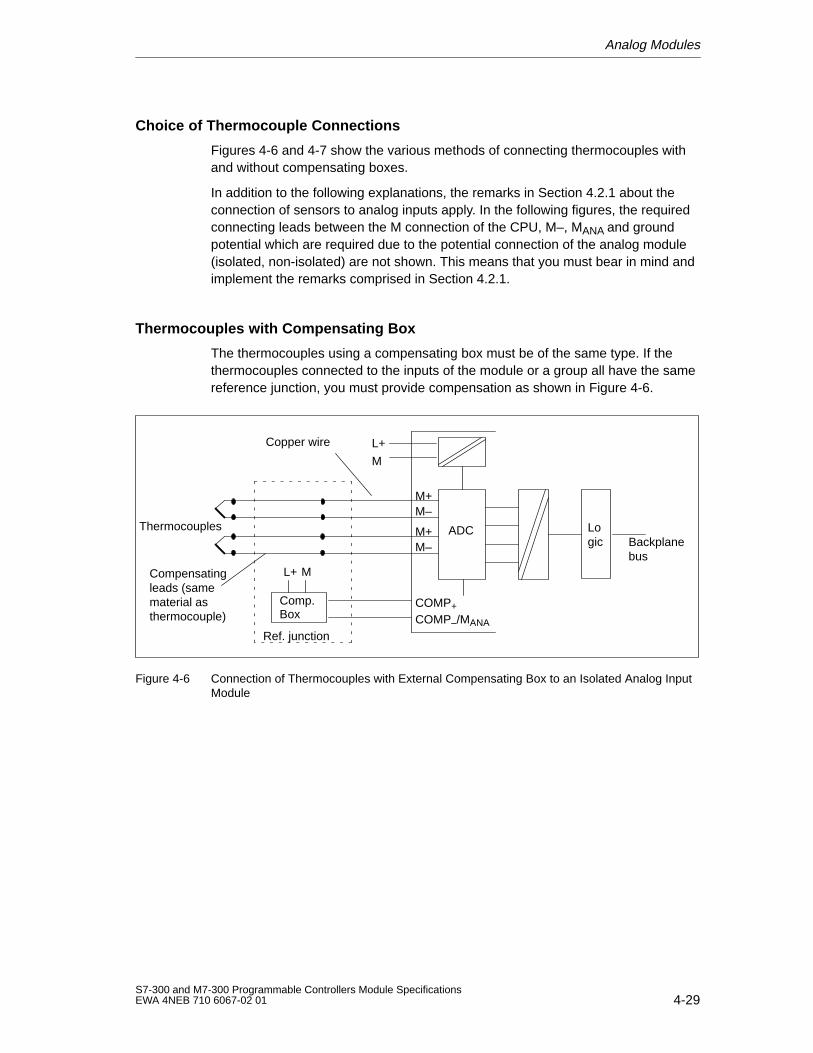
Analog Modules
4-29S7-300 and M7-300 Programmable Controllers Module SpecificationsEWA 4NEB 710 6067-02 01
Choice of Thermocouple Connections
Figures 4-6 and 4-7 show the various methods of connecting thermocouples withand without compensating boxes.
In addition to the following explanations, the remarks in Section 4.2.1 about theconnection of sensors to analog inputs apply. In the following figures, the requiredconnecting leads between the M connection of the CPU, M–, MANA and groundpotential which are required due to the potential connection of the analog module(isolated, non-isolated) are not shown. This means that you must bear in mind andimplement the remarks comprised in Section 4.2.1.
Thermocouples with Compensating Box
The thermocouples using a compensating box must be of the same type. If thethermocouples connected to the inputs of the module or a group all have the samereference junction, you must provide compensation as shown in Figure 4-6.
M+M–
M+M– Backplane
bus
ADC
M
L+
Compensatingleads (samematerial asthermocouple) Box
Comp.
Ref. junction
ML+
Copper wire
COMP–/MANA
COMP+
Thermocouples Logic
Figure 4-6 Connection of Thermocouples with External Compensating Box to an Isolated Analog InputModule
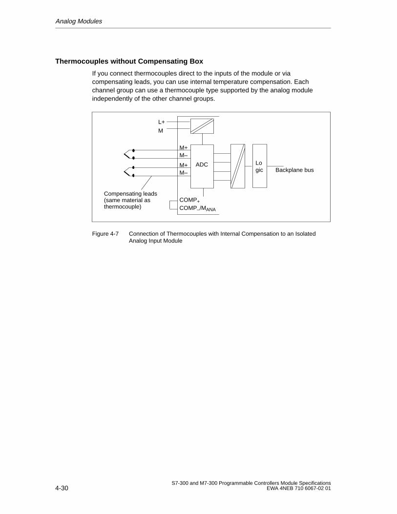
Analog Modules
4-30S7-300 and M7-300 Programmable Controllers Module Specifications
EWA 4NEB 710 6067-02 01
Thermocouples without Compensating Box
If you connect thermocouples direct to the inputs of the module or viacompensating leads, you can use internal temperature compensation. Eachchannel group can use a thermocouple type supported by the analog moduleindependently of the other channel groups.
M+M–
M+M–
ADC
M
L+
COMP–/MANA
COMP+
Compensating leads(same material asthermocouple)
Backplane busLogic
Figure 4-7 Connection of Thermocouples with Internal Compensation to an IsolatedAnalog Input Module
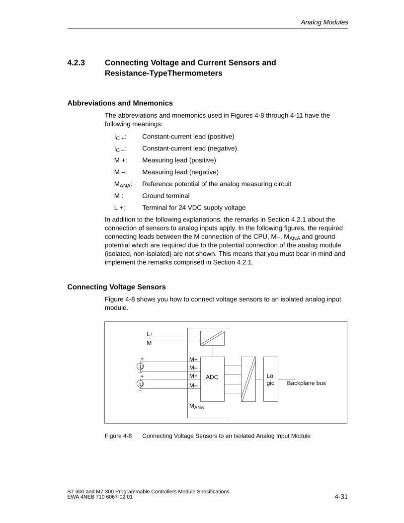
Analog Modules
4-31S7-300 and M7-300 Programmable Controllers Module SpecificationsEWA 4NEB 710 6067-02 01
4.2.3 Connecting Voltage and Current Sensors andResistance-TypeThermometers
Abbreviations and Mnemonics
The abbreviations and mnemonics used in Figures 4-8 through 4-11 have thefollowing meanings:
IC +: Constant-current lead (positive)
IC –: Constant-current lead (negative)
M +: Measuring lead (positive)
M –: Measuring lead (negative)
MANA: Reference potential of the analog measuring circuit
M : Ground terminal
L +: Terminal for 24 VDC supply voltage
In addition to the following explanations, the remarks in Section 4.2.1 about theconnection of sensors to analog inputs apply. In the following figures, the requiredconnecting leads between the M connection of the CPU, M–, MANA and groundpotential which are required due to the potential connection of the analog module(isolated, non-isolated) are not shown. This means that you must bear in mind andimplement the remarks comprised in Section 4.2.1.
Connecting Voltage Sensors
Figure 4-8 shows you how to connect voltage sensors to an isolated analog inputmodule.
M+
M
L+
M–
MANA
M+
M–ADC
+
–U
+
–U Backplane bus
Logic
Figure 4-8 Connecting Voltage Sensors to an Isolated Analog Input Module
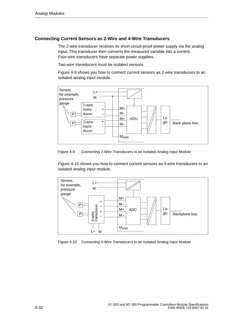
Analog Modules
4-32S7-300 and M7-300 Programmable Controllers Module Specifications
EWA 4NEB 710 6067-02 01
Connecting Current Sensors as 2-Wire and 4-Wire Transducers
The 2-wire transducer receives its short-circuit-proof power supply via the analoginput. This transducer then converts the measured variable into a current.Four-wire transducers have separate power supplies.
Two-wire transducers must be isolated sensors.
Figure 4-9 shows you how to connect current sensors as 2-wire transducers to anisolated analog input module.
M+
M
L+
M–
MANA
M+
M–
ADU2-wiretrans-ducer
2-wiretrans-ducerP
P
+–
+–
Sensor, for example,pressuregauge
Back-plane busLogic
Figure 4-9 Connecting 2-Wire Transducers to an Isolated Analog Input Module
Figure 4-10 shows you how to connect current sensors as 4-wire transducers to anisolated analog input module.
M+
M
L+
M–
MANA
M+
M–
ADCP
P
Sensor,for example,pressuregauge
tran
sduc
er4-
wire
+–
+–
L+ M
Backplane busLo-gic
Figure 4-10 Connecting 4-Wire Transducers to an Isolated Analog Input Module
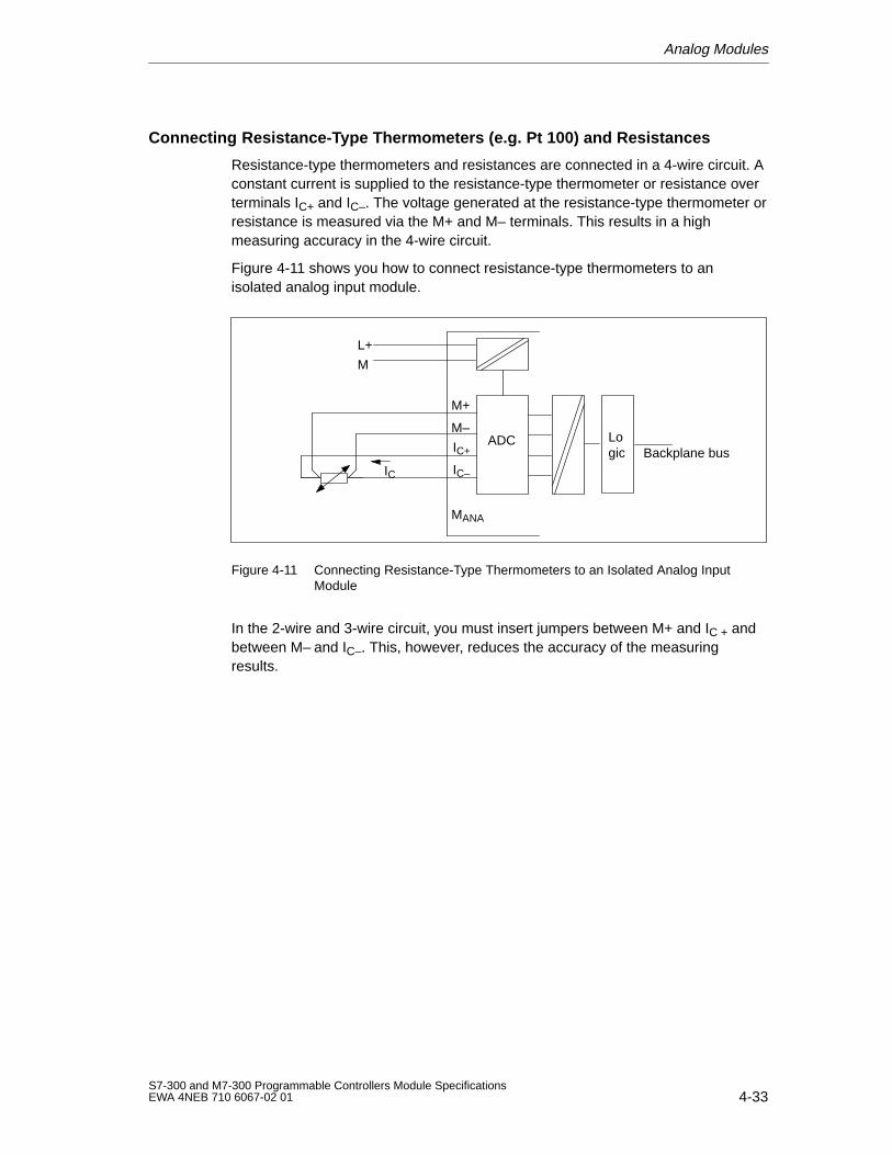
Analog Modules
4-33S7-300 and M7-300 Programmable Controllers Module SpecificationsEWA 4NEB 710 6067-02 01
Connecting Resistance-Type Thermometers (e.g. Pt 100) and Resistances
Resistance-type thermometers and resistances are connected in a 4-wire circuit. Aconstant current is supplied to the resistance-type thermometer or resistance overterminals IC+ and IC–. The voltage generated at the resistance-type thermometer orresistance is measured via the M+ and M– terminals. This results in a highmeasuring accuracy in the 4-wire circuit.
Figure 4-11 shows you how to connect resistance-type thermometers to anisolated analog input module.
M+
M
L+
M–
MANA
ADCIC+
IC–IC
Backplane busLogic
Figure 4-11 Connecting Resistance-Type Thermometers to an Isolated Analog InputModule
In the 2-wire and 3-wire circuit, you must insert jumpers between M+ and IC + andbetween M– and IC–. This, however, reduces the accuracy of the measuringresults.
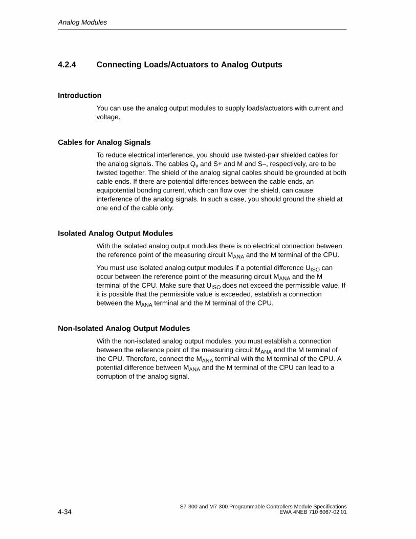
Analog Modules
4-34S7-300 and M7-300 Programmable Controllers Module Specifications
EWA 4NEB 710 6067-02 01
4.2.4 Connecting Loads/Actuators to Analog Outputs
Introduction
You can use the analog output modules to supply loads/actuators with current andvoltage.
Cables for Analog Signals
To reduce electrical interference, you should use twisted-pair shielded cables forthe analog signals. The cables Qv and S+ and M and S–, respectively, are to betwisted together. The shield of the analog signal cables should be grounded at bothcable ends. If there are potential differences between the cable ends, anequipotential bonding current, which can flow over the shield, can causeinterference of the analog signals. In such a case, you should ground the shield atone end of the cable only.
Isolated Analog Output Modules
With the isolated analog output modules there is no electrical connection betweenthe reference point of the measuring circuit MANA and the M terminal of the CPU.
You must use isolated analog output modules if a potential difference UISO canoccur between the reference point of the measuring circuit MANA and the Mterminal of the CPU. Make sure that UISO does not exceed the permissible value. Ifit is possible that the permissible value is exceeded, establish a connectionbetween the MANA terminal and the M terminal of the CPU.
Non-Isolated Analog Output Modules
With the non-isolated analog output modules, you must establish a connectionbetween the reference point of the measuring circuit MANA and the M terminal ofthe CPU. Therefore, connect the MANA terminal with the M terminal of the CPU. Apotential difference between MANA and the M terminal of the CPU can lead to acorruption of the analog signal.
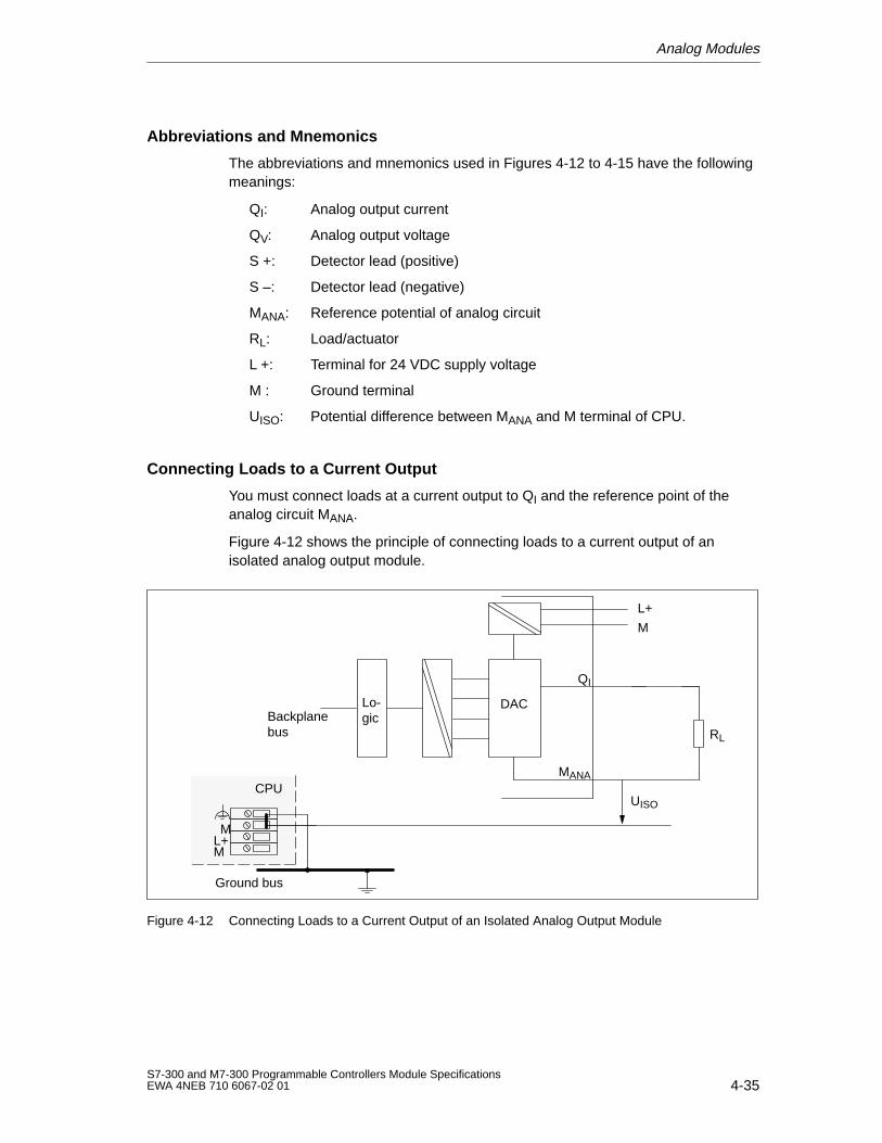
Analog Modules
4-35S7-300 and M7-300 Programmable Controllers Module SpecificationsEWA 4NEB 710 6067-02 01
Abbreviations and Mnemonics
The abbreviations and mnemonics used in Figures 4-12 to 4-15 have the followingmeanings:
QI: Analog output current
QV: Analog output voltage
S +: Detector lead (positive)
S –: Detector lead (negative)
MANA: Reference potential of analog circuit
RL: Load/actuator
L +: Terminal for 24 VDC supply voltage
M : Ground terminal
UISO: Potential difference between MANA and M terminal of CPU.
Connecting Loads to a Current Output
You must connect loads at a current output to QI and the reference point of theanalog circuit MANA.
Figure 4-12 shows the principle of connecting loads to a current output of anisolated analog output module.
M
L+
Backplanebus
DAC
RL
QI
MANA
ML+M
Ground bus
CPUUISO
Lo-gic
Figure 4-12 Connecting Loads to a Current Output of an Isolated Analog Output Module
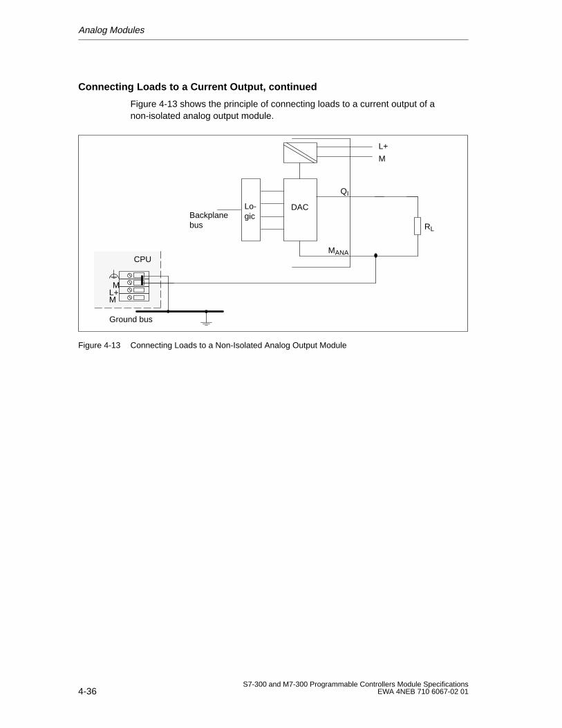
Analog Modules
4-36S7-300 and M7-300 Programmable Controllers Module Specifications
EWA 4NEB 710 6067-02 01
Connecting Loads to a Current Output, continued
Figure 4-13 shows the principle of connecting loads to a current output of anon-isolated analog output module.
M
L+
Backplanebus
DAC
RL
QI
MANA
ML+M
Ground bus
CPU
Lo-gic
Figure 4-13 Connecting Loads to a Non-Isolated Analog Output Module
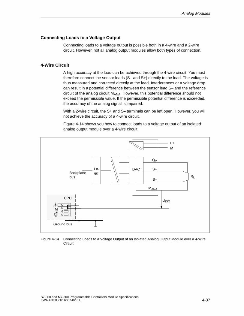
Analog Modules
4-37S7-300 and M7-300 Programmable Controllers Module SpecificationsEWA 4NEB 710 6067-02 01
Connecting Loads to a Voltage Output
Connecting loads to a voltage output is possible both in a 4-wire and a 2-wirecircuit. However, not all analog output modules allow both types of connection.
4-Wire Circuit
A high accuracy at the load can be achieved through the 4-wire circuit. You musttherefore connect the sensor leads (S– and S+) directly to the load. The voltage isthus measured and corrected directly at the load. Interferences or a voltage dropcan result in a potential difference between the sensor lead S– and the referencecircuit of the analog circuit MANA. However, this potential difference should notexceed the permissible value. If the permissible potential difference is exceeded,the accuracy of the analog signal is impaired.
With a 2-wire circuit, the S+ and S– terminals can be left open. However, you willnot achieve the accuracy of a 4-wire circuit.
Figure 4-14 shows you how to connect loads to a voltage output of an isolatedanalog output module over a 4-wire circuit.
M
L+
DAC
RL
QV
MANA
ML+M
Ground bus
CPU
S+
S–
UISO
Backplanebus
Lo-gic
Figure 4-14 Connecting Loads to a Voltage Output of an Isolated Analog Output Module over a 4-WireCircuit
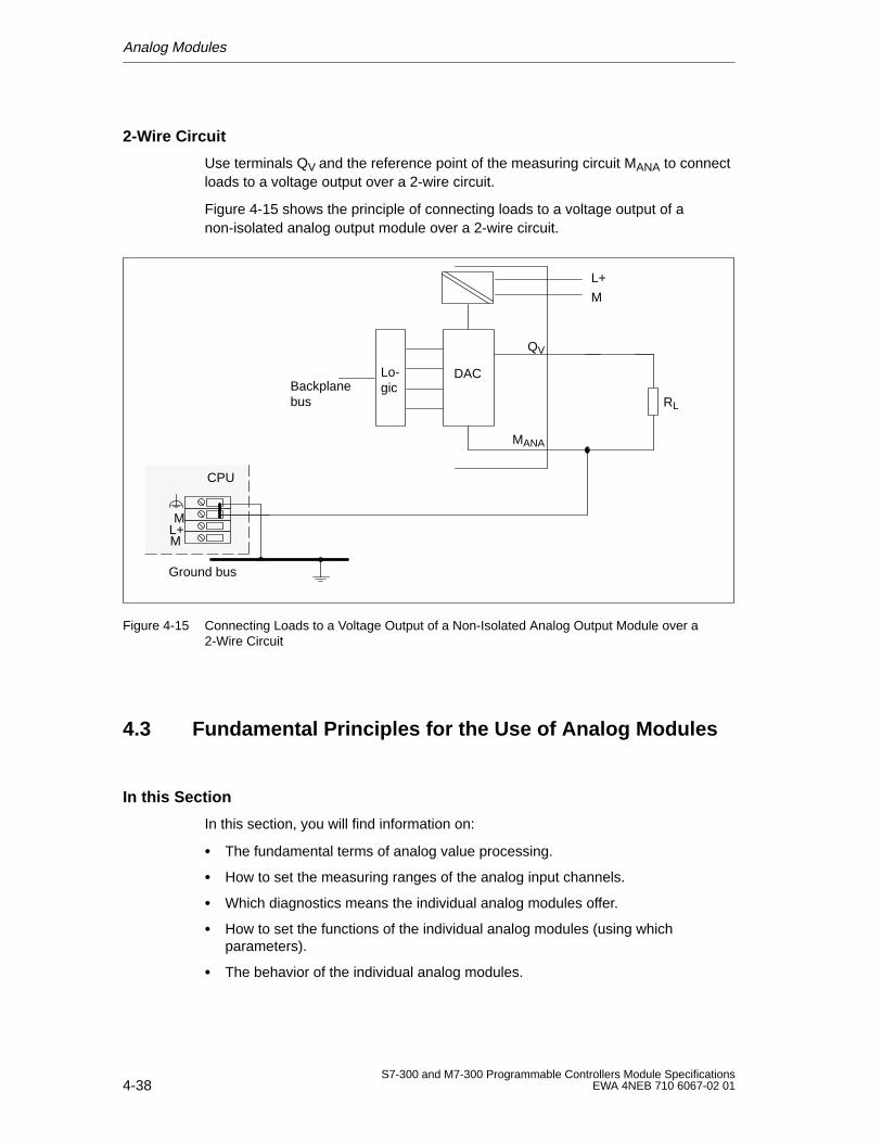
Analog Modules
4-38S7-300 and M7-300 Programmable Controllers Module Specifications
EWA 4NEB 710 6067-02 01
2-Wire Circuit
Use terminals QV and the reference point of the measuring circuit MANA to connectloads to a voltage output over a 2-wire circuit.
Figure 4-15 shows the principle of connecting loads to a voltage output of anon-isolated analog output module over a 2-wire circuit.
M
L+
Backplanebus
DAC
ML+M
Ground bus
CPU
Lo-gic
RL
QV
MANA
Figure 4-15 Connecting Loads to a Voltage Output of a Non-Isolated Analog Output Module over a2-Wire Circuit
4.3 Fundamental Principles for the Use of Analog Modules
In this Section
In this section, you will find information on:
The fundamental terms of analog value processing.
How to set the measuring ranges of the analog input channels.
Which diagnostics means the individual analog modules offer.
How to set the functions of the individual analog modules (using whichparameters).
The behavior of the individual analog modules.
Analog Modules
4-39S7-300 and M7-300 Programmable Controllers Module SpecificationsEWA 4NEB 710 6067-02 01
4.3.1 Conversion and Cycle Time of the Analog Input Channels
Introduction
In this section, you will find the definitions and relations of the conversion time andcycle time for the analog input modules.
Conversion Time
The conversion time consists of a basic conversion time and additional processingtimes of the module for:
Resistance measurement
Wire-break monitoring
The basic conversion time depends directly on the conversion method (integratingmethod, successive approximation) of the analog input channel. In the case ofintegrating conversion methods, the integration time has a direct influence on theconversion time. The integration time has a direct influence on the resolution. Youwill find the basic conversion times for the individual analog modules inSection 4.3.4. You set the integration time using STEP 7 (see Section 4.3.3).
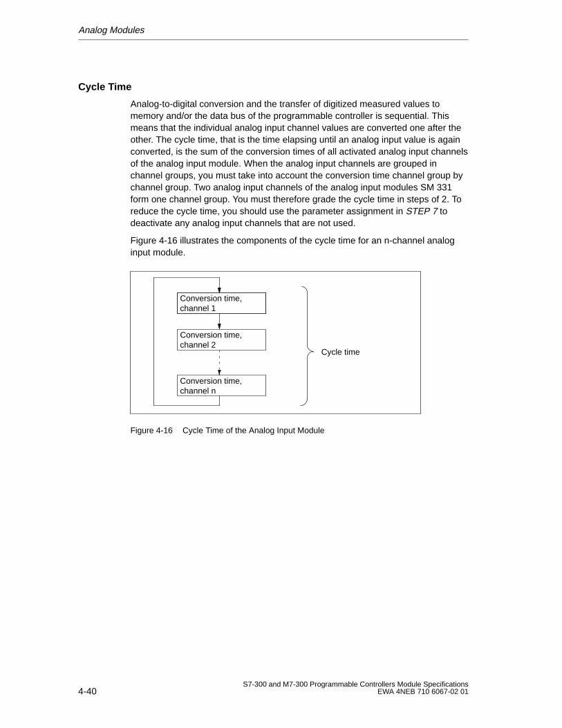
Analog Modules
4-40S7-300 and M7-300 Programmable Controllers Module Specifications
EWA 4NEB 710 6067-02 01
Cycle Time
Analog-to-digital conversion and the transfer of digitized measured values tomemory and/or the data bus of the programmable controller is sequential. Thismeans that the individual analog input channel values are converted one after theother. The cycle time, that is the time elapsing until an analog input value is againconverted, is the sum of the conversion times of all activated analog input channelsof the analog input module. When the analog input channels are grouped inchannel groups, you must take into account the conversion time channel group bychannel group. Two analog input channels of the analog input modules SM 331form one channel group. You must therefore grade the cycle time in steps of 2. Toreduce the cycle time, you should use the parameter assignment in STEP 7 todeactivate any analog input channels that are not used.
Figure 4-16 illustrates the components of the cycle time for an n-channel analoginput module.
Conversion time, channel 2
Conversion time, channel n
Cycle time
Conversion time, channel 1
Figure 4-16 Cycle Time of the Analog Input Module
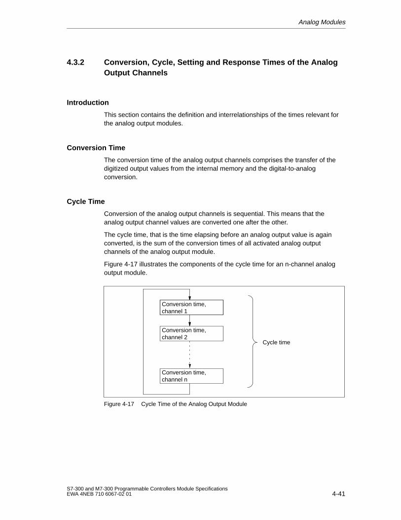
Analog Modules
4-41S7-300 and M7-300 Programmable Controllers Module SpecificationsEWA 4NEB 710 6067-02 01
4.3.2 Conversion, Cycle, Setting and Response Times of the AnalogOutput Channels
Introduction
This section contains the definition and interrelationships of the times relevant forthe analog output modules.
Conversion Time
The conversion time of the analog output channels comprises the transfer of thedigitized output values from the internal memory and the digital-to-analogconversion.
Cycle Time
Conversion of the analog output channels is sequential. This means that theanalog output channel values are converted one after the other.
The cycle time, that is the time elapsing before an analog output value is againconverted, is the sum of the conversion times of all activated analog outputchannels of the analog output module.
Figure 4-17 illustrates the components of the cycle time for an n-channel analogoutput module.
Conversion time, channel 1
Conversion time, channel 2
Conversion time, channel n
Cycle time
Figure 4-17 Cycle Time of the Analog Output Module
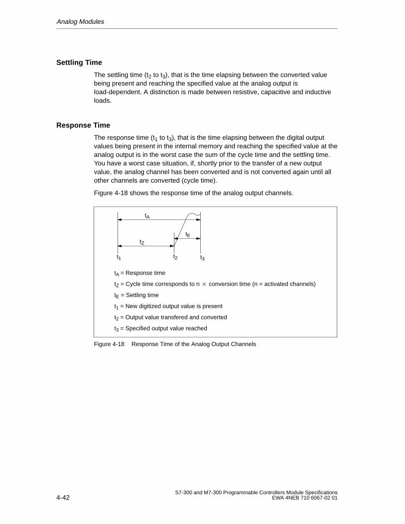
Analog Modules
4-42S7-300 and M7-300 Programmable Controllers Module Specifications
EWA 4NEB 710 6067-02 01
Settling Time
The settling time (t2 to t3), that is the time elapsing between the converted valuebeing present and reaching the specified value at the analog output isload-dependent. A distinction is made between resistive, capacitive and inductiveloads.
Response Time
The response time (t1 to t3), that is the time elapsing between the digital outputvalues being present in the internal memory and reaching the specified value at theanalog output is in the worst case the sum of the cycle time and the settling time.You have a worst case situation, if, shortly prior to the transfer of a new outputvalue, the analog channel has been converted and is not converted again until allother channels are converted (cycle time).
Figure 4-18 shows the response time of the analog output channels.
tA
tZ
tE
t1 t2
tA = Response time
tZ = Cycle time corresponds to n conversion time (n = activated channels)
tE = Settling time
t1 = New digitized output value is present
t2 = Output value transfered and converted
t3 = Specified output value reached
t3
Figure 4-18 Response Time of the Analog Output Channels
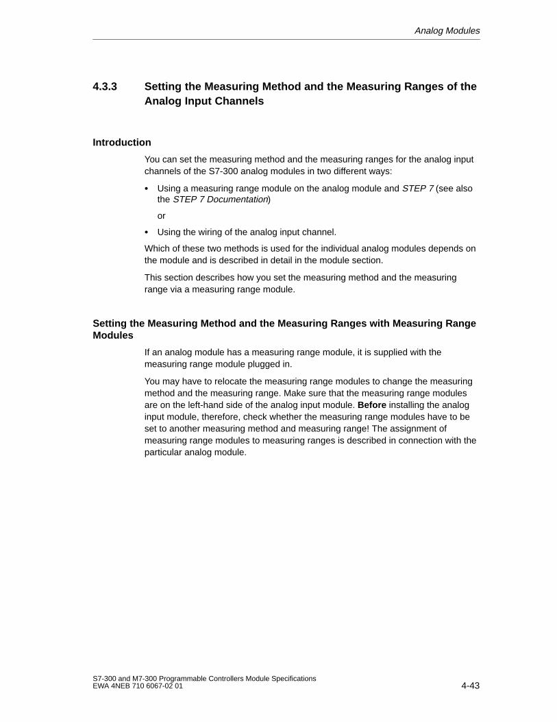
Analog Modules
4-43S7-300 and M7-300 Programmable Controllers Module SpecificationsEWA 4NEB 710 6067-02 01
4.3.3 Setting the Measuring Method and the Measuring Ranges of theAnalog Input Channels
Introduction
You can set the measuring method and the measuring ranges for the analog inputchannels of the S7-300 analog modules in two different ways:
Using a measuring range module on the analog module and STEP 7 (see alsothe STEP 7 Documentation)
or
Using the wiring of the analog input channel.
Which of these two methods is used for the individual analog modules depends onthe module and is described in detail in the module section.
This section describes how you set the measuring method and the measuringrange via a measuring range module.
Setting the Measuring Method and the Measuring Ranges with Measuring RangeModules
If an analog module has a measuring range module, it is supplied with themeasuring range module plugged in.
You may have to relocate the measuring range modules to change the measuringmethod and the measuring range. Make sure that the measuring range modulesare on the left-hand side of the analog input module. Before installing the analoginput module, therefore, check whether the measuring range modules have to beset to another measuring method and measuring range! The assignment ofmeasuring range modules to measuring ranges is described in connection with theparticular analog module.
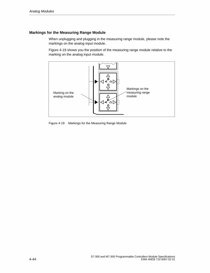
Analog Modules
4-44S7-300 and M7-300 Programmable Controllers Module Specifications
EWA 4NEB 710 6067-02 01
Markings for the Measuring Range Module
When unplugging and plugging in the measuring range module, please note themarkings on the analog input module.
Figure 4-19 shows you the position of the measuring range module relative to themarking on the analog input module.
Marking on theanalog module
Markings on themeasuring rangemodule
A
B C
D
A
B C
D
Figure 4-19 Markings for the Measuring Range Module
Analog Modules
4-45S7-300 and M7-300 Programmable Controllers Module SpecificationsEWA 4NEB 710 6067-02 01
Resetting the Measuring Range Module
If you have to reset a measuring range module, proceed as follows (example:analog input module SM 331; AI 8 12 Bit):
1. Use a screwdriver to ease the measuring range module out of the analog inputmodule with a single lift.
Note: Make sure that you do not insert the screwdriver in the latching windowof the measuring range module if you require more than one lift to ease themeasuring range module out. You might thus damage its contacts.
1
2
Figure 4-20 Easing a Measuring Range Module out of Analog Input Module SM 331;AI 8 12 Bit
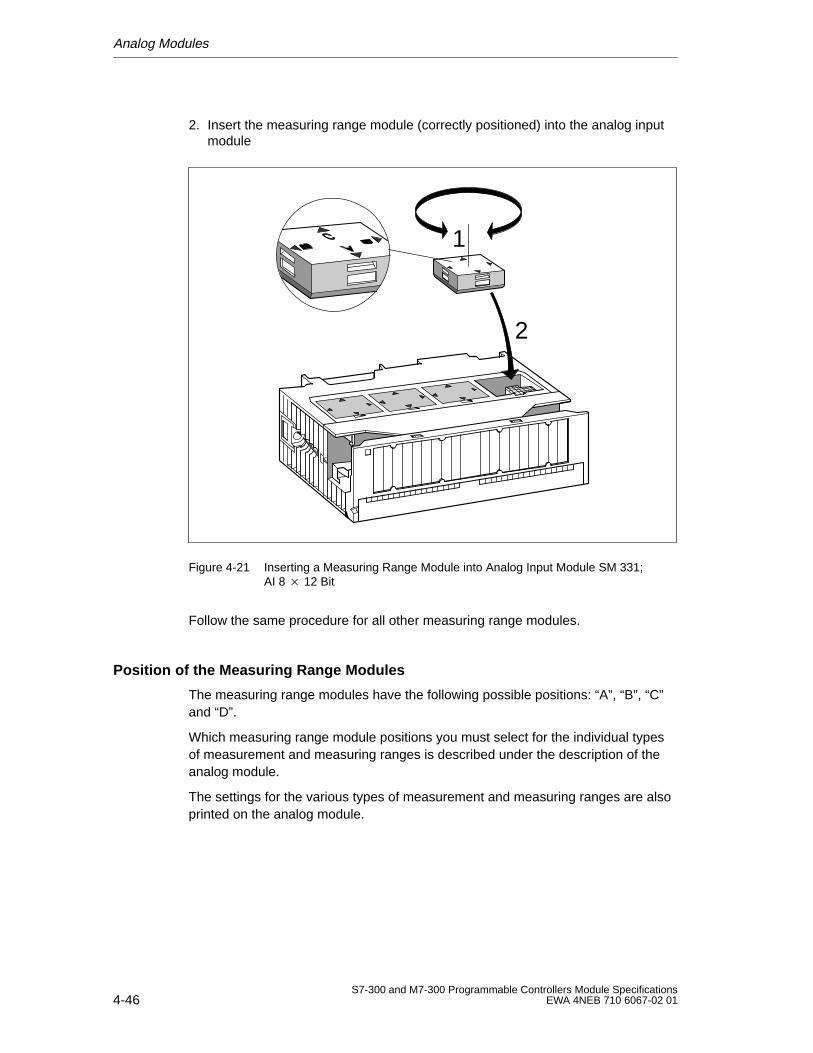
Analog Modules
4-46S7-300 and M7-300 Programmable Controllers Module Specifications
EWA 4NEB 710 6067-02 01
2. Insert the measuring range module (correctly positioned) into the analog inputmodule
1
2
Figure 4-21 Inserting a Measuring Range Module into Analog Input Module SM 331;AI 8 12 Bit
Follow the same procedure for all other measuring range modules.
Position of the Measuring Range Modules
The measuring range modules have the following possible positions: “A”, “B”, “C”and “D”.
Which measuring range module positions you must select for the individual typesof measurement and measuring ranges is described under the description of theanalog module.
The settings for the various types of measurement and measuring ranges are alsoprinted on the analog module.

Analog Modules
4-47S7-300 and M7-300 Programmable Controllers Module SpecificationsEWA 4NEB 710 6067-02 01
4.3.4 Parameters of the Analog Modules
Introduction
This section contains a summary of the analog modules and their parameters.
Parameter Assignment
Use STEP 7 to assign the parameters to the analog modules. You must carry outthis setting in the STOP mode of the CPU. On a transition from STOP to RUNmode, the CPU then transfers the parameters to the individual analog modules.
Alternatively, you can also change some of the parameters in the user programwith SFC 55. You can find the relevant parameters in Appendix A or in Tables 4-19and 4-20. The parameters set with STEP 7 in the CPU RUN mode can betransferred to the analog module using SFCs 56 and 57 (see Reference ManualSystem and Standard Functions).
For the two parameter assignment alternatives, we subdivide the parameters into:
Static parameters and
Dynamic parameters.
The following table shows the characteristics of the static and dynamicparameters.
Parameter Settable with CPU OperatingState
Static Programming device STOP
Dynamic Programming device STOP
SFC 55 in the user program RUN
Analog Modules
4-48S7-300 and M7-300 Programmable Controllers Module Specifications
EWA 4NEB 710 6067-02 01
Programmable Characteristics
You can program the characteristics of the analog modules by means of thefollowing parameters in STEP 7:
For input channels
– Interrupt enable
– Limit value interrupt
– Diagnostics interrupt
– Measurement
For output channels
– Interrupt enable
– Diagnostics interrupt
– Substitute values
– Output
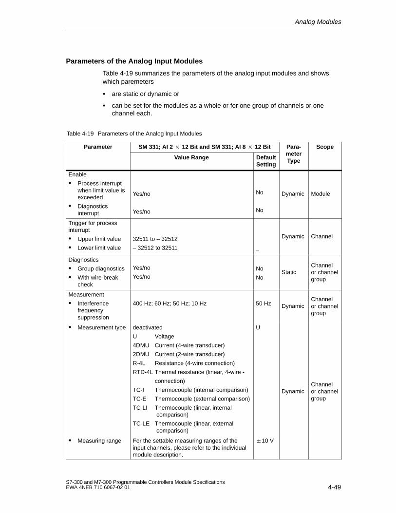
Analog Modules
4-49S7-300 and M7-300 Programmable Controllers Module SpecificationsEWA 4NEB 710 6067-02 01
Parameters of the Analog Input Modules
Table 4-19 summarizes the parameters of the analog input modules and showswhich paremeters
are static or dynamic or
can be set for the modules as a whole or for one group of channels or onechannel each.
Table 4-19 Parameters of the Analog Input Modules
Parameter SM 331; AI 2 12 Bit and SM 331; AI 8 12 Bit Para-meter
Scope
Value Range DefaultSetting
meterType
p
Enable
Process interruptwhen limit value isexceeded
Diagnosticsinterrupt
Yes/no
Yes/no
No
No
Dynamic Module
Trigger for processinterrupt
Upper limit value
Lower limit value
32511 to – 32512
– 32512 to 32511 –
Dynamic Channel
Diagnostics
Group diagnostics
With wire-breakcheck
Yes/no
Yes/noNo
NoStatic
Channelor channelgroup
Measurement
Interferencefrequencysuppression
400 Hz; 60 Hz; 50 Hz; 10 Hz 50 Hz DynamicChannelor channelgroup
Measurement type deactivated
U Voltage
4DMU Current (4-wire transducer)
2DMU Current (2-wire transducer)
R-4L Resistance (4-wire connection)
RTD-4L Thermal resistance (linear, 4-wire -
connection)
TC-I Thermocouple (internal comparison)
TC-E Thermocouple (external comparison)
TC-LI Thermocouple (linear, internal comparison)
TC-LE Thermocouple (linear, external comparison)
U
DynamicChannelor channelgroup
Measuring range For the settable measuring ranges of theinput channels, please refer to the individualmodule description.
10 V
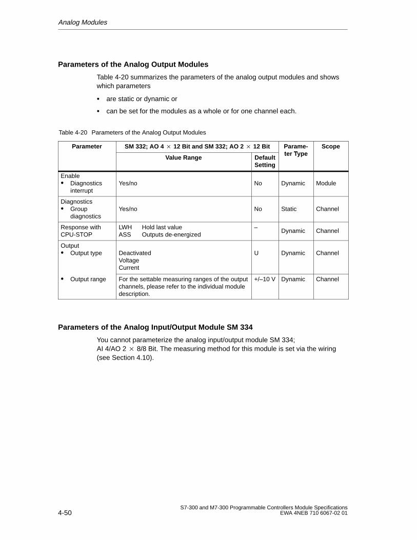
Analog Modules
4-50S7-300 and M7-300 Programmable Controllers Module Specifications
EWA 4NEB 710 6067-02 01
Parameters of the Analog Output Modules
Table 4-20 summarizes the parameters of the analog output modules and showswhich parameters
are static or dynamic or
can be set for the modules as a whole or for one channel each.
Table 4-20 Parameters of the Analog Output Modules
Parameter SM 332; AO 4 12 Bit and SM 332; AO 2 12 Bit Parame-ter Type
Scope
Value Range DefaultSetting
ter Typep
Enable Diagnostics
interruptYes/no No Dynamic Module
Diagnostics Group
diagnosticsYes/no No Static Channel
Response withCPU-STOP
LWH Hold last valueASS Outputs de-energized
–Dynamic Channel
Output Output type Deactivated
VoltageCurrent
U Dynamic Channel
Output range For the settable measuring ranges of the outputchannels, please refer to the individual moduledescription.
+/–10 V Dynamic Channel
Parameters of the Analog Input/Output Module SM 334
You cannot parameterize the analog input/output module SM 334;AI 4/AO 2 8/8 Bit. The measuring method for this module is set via the wiring(see Section 4.10).
Analog Modules
4-51S7-300 and M7-300 Programmable Controllers Module SpecificationsEWA 4NEB 710 6067-02 01
4.3.5 Diagnostics of the Analog Modules
Introduction
This Section contains tables listing the diagnostic messages of the analogmodules.
What does Diagnostics Mean?
Use diagnostics to find out if and which errors have occurred on analogprocessing. When detecting an error, the analog input modules supply signal value“7FFFH”, independent of the parameter assignment.
Parameterizing Diagnostics
Use STEP 7 to set the diagnostics parameters.
Diagnostics Evaluation
For the purpose of diagnostics evaluation, a distinction is made betweenprogrammable and non-programmable diagnostics messages. With theprogrammable diagnostics messages, evaluation is made only if a diagnosticsenable has been programmed (in the “group diagnostics” parameter). Thenon-programmable diagnostics messages are always evaluated, irrespective of thediagnostics enable setting.
Only evaluated diagnostics messages will activate the following functions:
Group error LED on the analog module lights up,
Diagnostics message is transferred to CPU,
Diagnostics interrupt is triggered (only if you have enabled the diagnosticsinterrupt by parameter).
See also Appendix B and the reference manual Systems and Standard Functionsfor diagnostics evaluation in the user program with SFC.
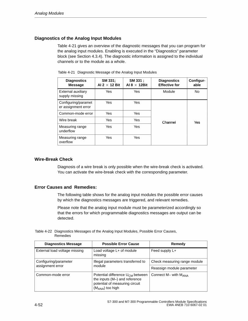
Analog Modules
4-52S7-300 and M7-300 Programmable Controllers Module Specifications
EWA 4NEB 710 6067-02 01
Diagnostics of the Analog Input Modules
Table 4-21 gives an overview of the diagnostic messages that you can program forthe analog input modules. Enabling is executed in the “Diagnostics” parameterblock (see Section 4.3.4). The diagnostic information is assigned to the individualchannels or to the module as a whole.
Table 4-21 Diagnostic Message of the Analog Input Modules
DiagnosticsMessage
SM 331;AI 2 12 Bit
SM 331 ;AI 8 12Bit
DiagnosticsEffective for
Configur-able
External auxiliarysupply missing
Yes Yes Module No
Configuring/parameter assignment error
Yes Yes
Common-mode error Yes Yes
Wire break Yes YesChannel Yes
Measuring rangeunderflow
Yes YesChannel Yes
Measuring rangeoverflow
Yes Yes
Wire-Break Check
Diagnosis of a wire break is only possible when the wire-break check is activated.You can activate the wire-break check with the corresponding parameter.
Error Causes and Remedies:
The following table shows for the analog input modules the possible error causesby which the diagnostics messages are triggered, and relevant remedies.
Please note that the analog input module must be parameterized accordingly sothat the errors for which programmable diagnostics messages are output can bedetected.
Table 4-22 Diagnostics Messages of the Analog Input Modules, Possible Error Causes,Remedies
Diagnostics Message Possible Error Cause Remedy
External load voltage missing Load voltage L+ of modulemissing
Feed supply L+
Configuring/parameterassignment error
Illegal parameters transferred tomodule
Check measuring range moduleg g passignment error
g pmodule
Reassign module parameter
Common-mode error Potential difference UCM betweenthe inputs (M–) and referencepotential of measuring circuit(MANA) too high
Connect M– with MANA
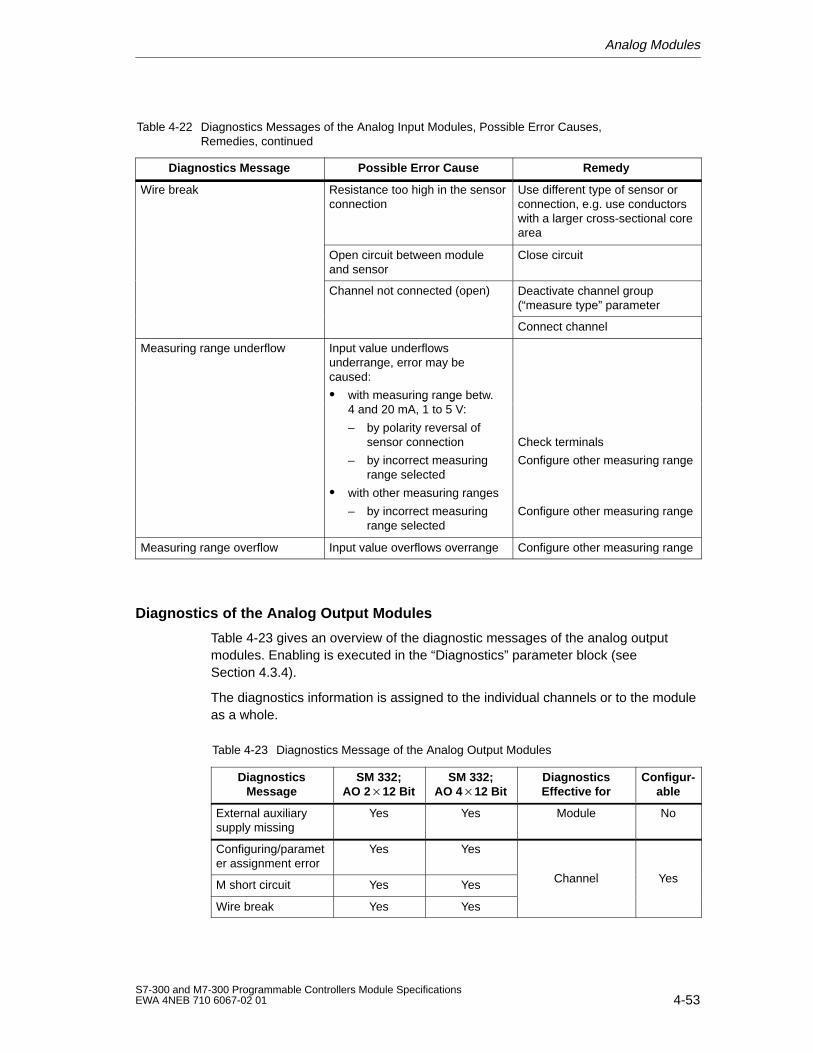
Analog Modules
4-53S7-300 and M7-300 Programmable Controllers Module SpecificationsEWA 4NEB 710 6067-02 01
Table 4-22 Diagnostics Messages of the Analog Input Modules, Possible Error Causes,Remedies, continued
Diagnostics Message RemedyPossible Error Cause
Wire break Resistance too high in the sensorconnection
Use different type of sensor orconnection, e.g. use conductorswith a larger cross-sectional corearea
Open circuit between moduleand sensor
Close circuit
Channel not connected (open) Deactivate channel group(“measure type” parameter
Connect channel
Measuring range underflow Input value underflowsunderrange, error may becaused:
with measuring range betw.4 d 20 A 1 t 5 Vwith measuring range betw.4 and 20 mA, 1 to 5 V:
– by polarity reversal ofsensor connection
– by incorrect measuringrange selected
Check terminals
Configure other measuring rangey grange selected
with other measuring ranges
– by incorrect measuringrange selected
g g g
Configure other measuring range
Measuring range overflow Input value overflows overrange Configure other measuring range
Diagnostics of the Analog Output Modules
Table 4-23 gives an overview of the diagnostic messages of the analog outputmodules. Enabling is executed in the “Diagnostics” parameter block (seeSection 4.3.4).
The diagnostics information is assigned to the individual channels or to the moduleas a whole.
Table 4-23 Diagnostics Message of the Analog Output Modules
DiagnosticsMessage
SM 332;AO 212 Bit
SM 332;AO 412 Bit
DiagnosticsEffective for
Configur-able
External auxiliarysupply missing
Yes Yes Module No
Configuring/parameter assignment error
Yes Yes
Channel YesM short circuit Yes Yes Channel Yes
Wire break Yes Yes
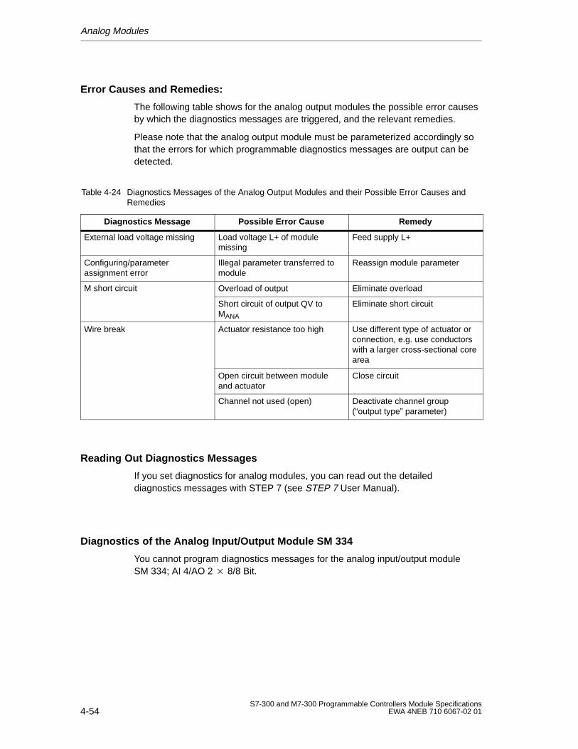
Analog Modules
4-54S7-300 and M7-300 Programmable Controllers Module Specifications
EWA 4NEB 710 6067-02 01
Error Causes and Remedies:
The following table shows for the analog output modules the possible error causesby which the diagnostics messages are triggered, and the relevant remedies.
Please note that the analog output module must be parameterized accordingly sothat the errors for which programmable diagnostics messages are output can bedetected.
Table 4-24 Diagnostics Messages of the Analog Output Modules and their Possible Error Causes andRemedies
Diagnostics Message Possible Error Cause Remedy
External load voltage missing Load voltage L+ of modulemissing
Feed supply L+
Configuring/parameterassignment error
Illegal parameter transferred tomodule
Reassign module parameter
M short circuit Overload of output Eliminate overload
Short circuit of output QV toMANA
Eliminate short circuit
Wire break Actuator resistance too high Use different type of actuator orconnection, e.g. use conductorswith a larger cross-sectional corearea
Open circuit between moduleand actuator
Close circuit
Channel not used (open) Deactivate channel group(“output type” parameter)
Reading Out Diagnostics Messages
If you set diagnostics for analog modules, you can read out the detaileddiagnostics messages with STEP 7 (see STEP 7 User Manual).
Diagnostics of the Analog Input/Output Module SM 334
You cannot program diagnostics messages for the analog input/output moduleSM 334; AI 4/AO 2 8/8 Bit.
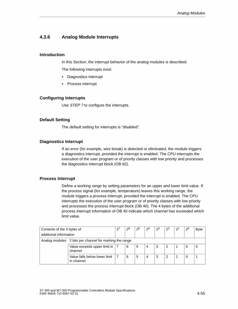
Analog Modules
4-55S7-300 and M7-300 Programmable Controllers Module SpecificationsEWA 4NEB 710 6067-02 01
4.3.6 Analog Module Interrupts
Introduction
In this Section, the interrupt behavior of the analog modules is described.
The following interrupts exist:
Diagnostics interrupt
Process interrupt
Configuring Interrupts
Use STEP 7 to configure the interrupts.
Default Setting
The default setting for interrupts is “disabled”.
Diagnostics Interrupt
If an error (for example, wire break) is detected or eliminated, the module triggersa diagnostics interrupt, provided the interrupt is enabled. The CPU interrupts theexecution of the user program or of priority classes with low priority and processesthe diagnostics interrupt block (OB 82).
Process Interrupt
Define a working range by setting parameters for an upper and lower limit value. Ifthe process signal (for example, temperature) leaves this working range, themodule triggers a process interrupt, provided the interrupt is enabled. The CPUinterrupts the execution of the user program or of priority classes with low priorityand processes the process interrupt block (OB 40). The 4 bytes of the additionalprocess interrupt information of OB 40 indicate which channel has exceeded whichlimit value.
Contents of the 4 bytes of
additional information
27 26 25 24 23 22 21 20 Byte
Analog modules 2 bits per channel for marking the rangeg
Value exceeds upper limit inchannel
7 6 5 4 3 2 1 0 0
Value falls below lower limitin channel
7 6 5 4 3 2 1 0 1
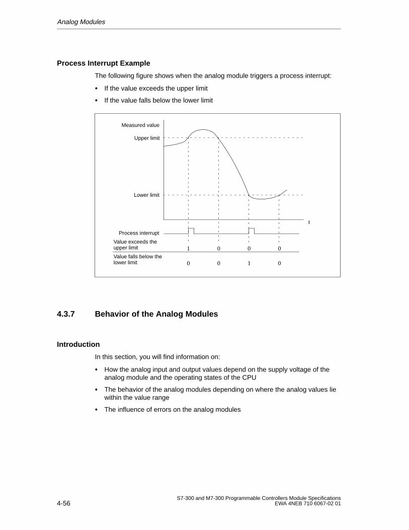
Analog Modules
4-56S7-300 and M7-300 Programmable Controllers Module Specifications
EWA 4NEB 710 6067-02 01
Process Interrupt Example
The following figure shows when the analog module triggers a process interrupt:
If the value exceeds the upper limit
If the value falls below the lower limit
Value exceeds the upper limit
Value falls below thelower limit
Lower limit
Upper limit
t
Process interrupt
1 0 0 0
0 0 01
Measured value
4.3.7 Behavior of the Analog Modules
Introduction
In this section, you will find information on:
How the analog input and output values depend on the supply voltage of theanalog module and the operating states of the CPU
The behavior of the analog modules depending on where the analog values liewithin the value range
The influence of errors on the analog modules
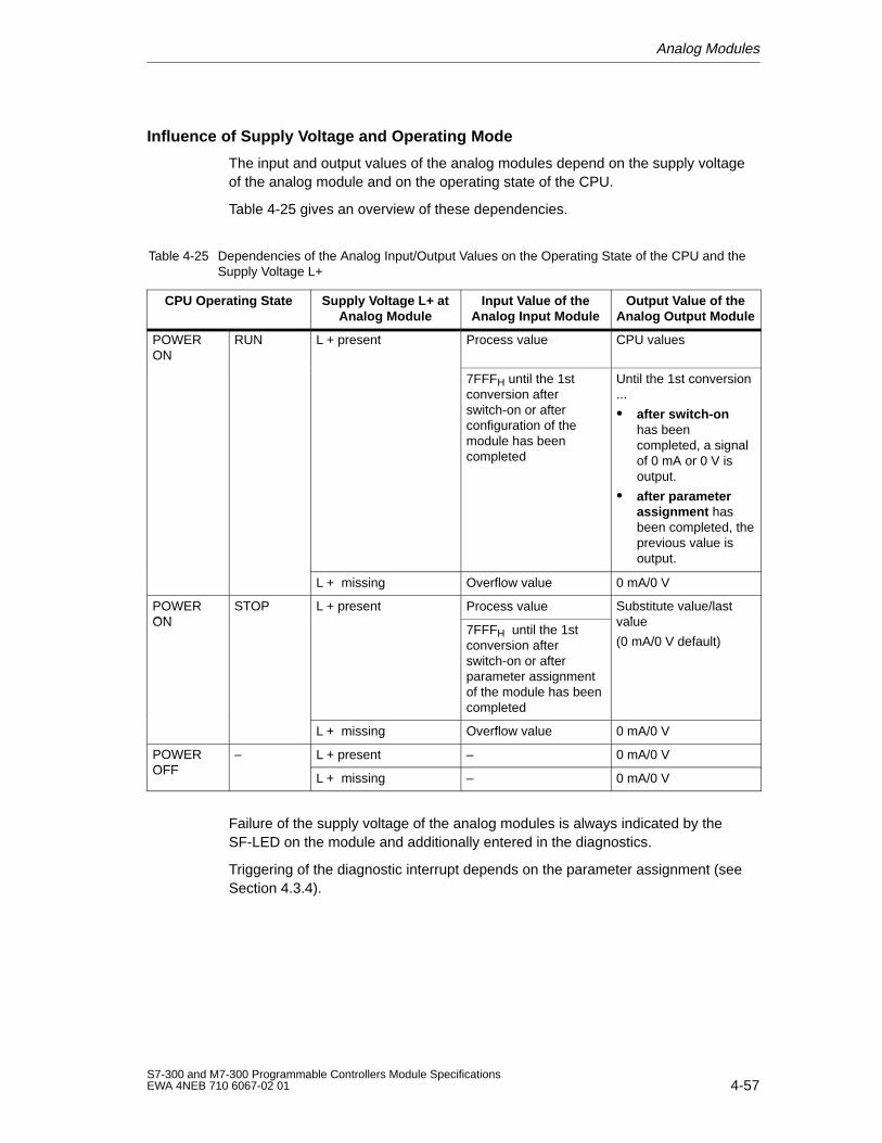
Analog Modules
4-57S7-300 and M7-300 Programmable Controllers Module SpecificationsEWA 4NEB 710 6067-02 01
Influence of Supply Voltage and Operating Mode
The input and output values of the analog modules depend on the supply voltageof the analog module and on the operating state of the CPU.
Table 4-25 gives an overview of these dependencies.
Table 4-25 Dependencies of the Analog Input/Output Values on the Operating State of the CPU and theSupply Voltage L+
CPU Operating State Supply V oltage L+ atAnalog Module
Input V alue of theAnalog Input Module
Output V alue of theAnalog Output Module
POWERON
RUN L + present Process value CPU values
7FFFH until the 1stconversion afterswitch-on or afterconfiguration of themodule has beencompleted
Until the 1st conversion...
after switch-on has beencompleted, a signalof 0 mA or 0 V isoutput.
after parameterassignment hasbeen completed, theprevious value isoutput.
L + missing Overflow value 0 mA/0 V
POWERON
STOP L + present Process value Substitute value/lastvalueON
p
7FFFH until the 1stconversion afterswitch-on or afterparameter assignmentof the module has beencompleted
value
(0 mA/0 V default)
L + missing Overflow value 0 mA/0 V
POWEROFF
– L + present – 0 mA/0 VOFF
L + missing – 0 mA/0 V
Failure of the supply voltage of the analog modules is always indicated by theSF-LED on the module and additionally entered in the diagnostics.
Triggering of the diagnostic interrupt depends on the parameter assignment (seeSection 4.3.4).
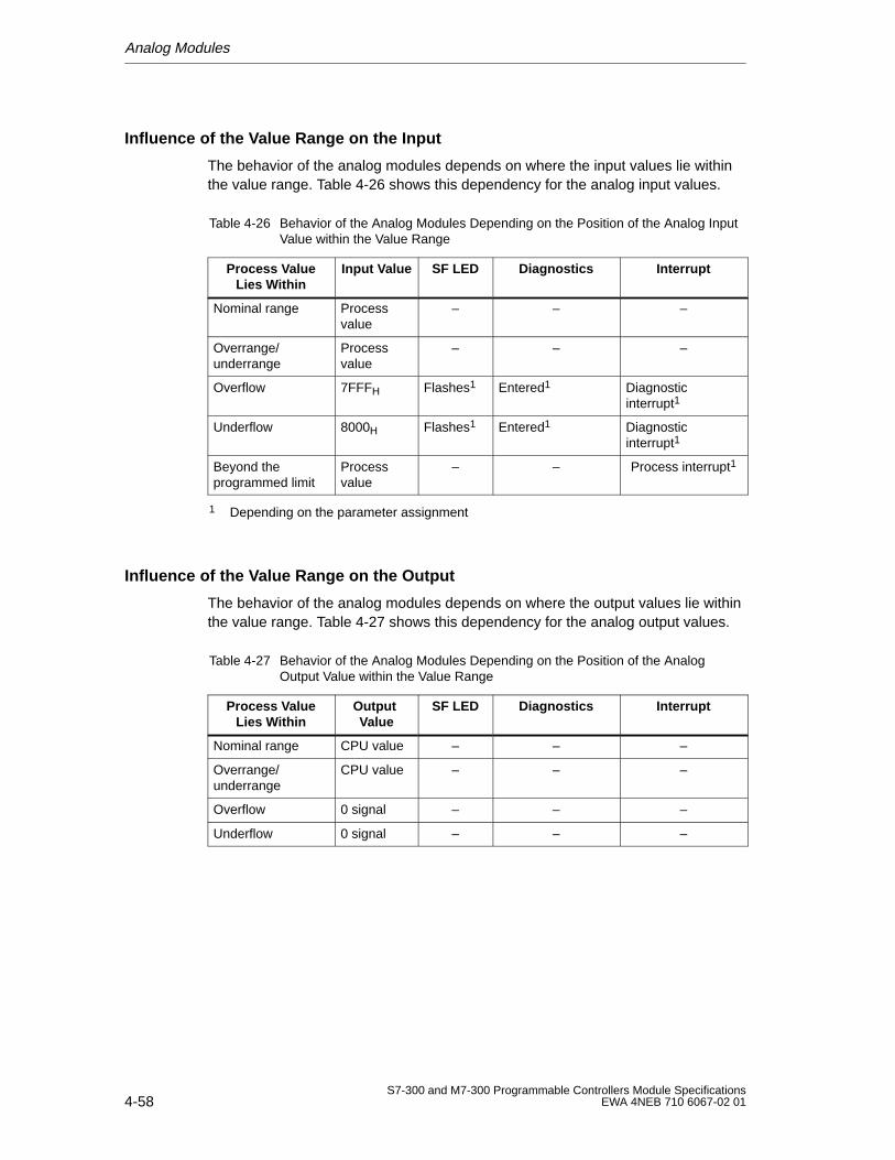
Analog Modules
4-58S7-300 and M7-300 Programmable Controllers Module Specifications
EWA 4NEB 710 6067-02 01
Influence of the Value Range on the Input
The behavior of the analog modules depends on where the input values lie withinthe value range. Table 4-26 shows this dependency for the analog input values.
Table 4-26 Behavior of the Analog Modules Depending on the Position of the Analog InputValue within the Value Range
Process V alueLies W ithin
Input Value SF LED Diagnostics Interrupt
Nominal range Processvalue
– – –
Overrange/underrange
Processvalue
– – –
Overflow 7FFFH Flashes1 Entered1 Diagnosticinterrupt1
Underflow 8000H Flashes1 Entered1 Diagnosticinterrupt1
Beyond theprogrammed limit
Processvalue
– – Process interrupt1
1 Depending on the parameter assignment
Influence of the Value Range on the Output
The behavior of the analog modules depends on where the output values lie withinthe value range. Table 4-27 shows this dependency for the analog output values.
Table 4-27 Behavior of the Analog Modules Depending on the Position of the AnalogOutput Value within the Value Range
Process V alueLies W ithin
Output Value
SF LED Diagnostics Interrupt
Nominal range CPU value – – –
Overrange/underrange
CPU value – – –
Overflow 0 signal – – –
Underflow 0 signal – – –
Analog Modules
4-59S7-300 and M7-300 Programmable Controllers Module SpecificationsEWA 4NEB 710 6067-02 01
Influence of Faults/Errors
In the case of analog modules with diagnostics capability and the appropriateparameter assignment (see Section 4.3.4 “Parameters of the Analog Modules”),faults/errors can cause a diagnostic entry and a diagnostic interrupt. Tables 4-19and 4-21 in Section 4.3.5 list the possible faults/errors.
The SF LED flashes also if external faults/errors occur, independent of theoperating state of the CPU (with POWER ON).
4.4 Analog Input Module SM 331; AI 8 12 Bit
In this Section
In this section, you will find information on:
The characteristics of the analog input module SM 331; AI 8 12 Bit
The technical specifications of the analog input module SM 331; AI 8 12 Bit
You will also learn:
How to start up the analog input module SM 331; AI 8 12 Bit
Which measuring ranges the analog input module SM 331; AI 8 12 Bit has
Which parameters can be used to influence the characteristics of the analoginput module SM 331; AI 8 12 Bit
Analog Modules
4-60S7-300 and M7-300 Programmable Controllers Module Specifications
EWA 4NEB 710 6067-02 01
4.4.1 Characteristic Features and Technical Specifications of theAnalog Input Module SM 331; AI 8 12 Bit
Order No.
6ES7 331-7KF01-0AB0
Characteristic Features
The analog input module SM 331; AI 8 12 Bit has the following characteristicfeatures:
8 inputs in 4 channel groups
Measured-value resolution; settable per group (depending on the integrationtime set)
– 9 bits + sign
– 12 Bit + sign
– 14 Bit + sign
Measuring method selectable per channel group:
– Voltage
– Current
– Resistance
– Temperature
Arbitrary measuring range selection per channel group
Programmable diagnostics
Programmable diagnostic interrupt
Two channels with limit monitoring
Programmable limit interrupt
Galvanic isolation to CPU
Galvanic isolation to load voltage (not for 2-wire transducer)
Resolution
The resolution of the measured value is a direct function of the integration timeselected. In other words the longer the integration time for an analog input channel,the more accurate the resolution of the measured value will be (see TechnicalSpecifications of the analog input module and Table 4-3).
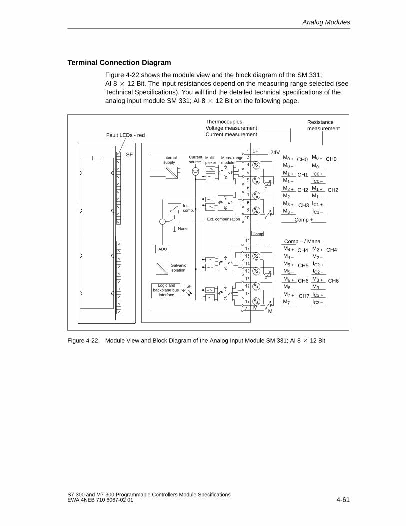
Analog Modules
4-61S7-300 and M7-300 Programmable Controllers Module SpecificationsEWA 4NEB 710 6067-02 01
Terminal Connection Diagram
Figure 4-22 shows the module view and the block diagram of the SM 331;AI 8 12 Bit. The input resistances depend on the measuring range selected (seeTechnical Specifications). You will find the detailed technical specifications of theanalog input module SM 331; AI 8 12 Bit on the following page.
M3
Comp – / Mana
Fault LEDs - red
Thermocouples,Voltage measurementCurrent measurement
Resistancemeasurement
M0 +
M0
M1 +
Comp +
SFInternal supply
MM
L+Current source
Multi-plexer
Meas. rangemodule
Ext. compensation
None
ADU
Galvanicisolation
Logic andbackplane bus
interface
SF
+
Int.comp.
CH0 M0 + CH0M0IC0 +CH1
M1 IC0
M2 + CH2 M1 + CH2M2 M1
M3 + CH3 IC1 +
IC1
M4 +
M4
M5 +
CH4 M2 + CH4M2IC2 +CH5
M5 IC2
M6 + CH6 M3 + CH6M6 M3
M7 + CH7 IC3 +
M7 IC3
Comp
24V
T
Figure 4-22 Module View and Block Diagram of the Analog Input Module SM 331; AI 8 12 Bit
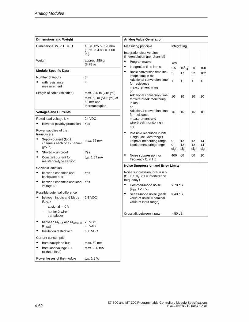
Analog Modules
4-62S7-300 and M7-300 Programmable Controllers Module Specifications
EWA 4NEB 710 6067-02 01
Dimensions and W eight
Dimensions W H D 40 125 120mm(1.56 4.88 4.68in.)
Weight approx. 250 g(8.75 oz.)
Module-Specific Data
Number of inputs
with resistancemeasurement
8
4
Length of cable (shielded) max. 200 m (218 yd.)
max. 50 m (54.5 yd.) at80 mV andthermocouples
Voltages and Currents
Rated load voltage L +
Reverse polarity protection
24 VDC
Yes
Power supplies of thetransducers
Supply current (for 2channels each of a channelgroup):
Short-circuit-proof
Constant current forresistance-type sensor
max: 62 mA
Yes
typ. 1.67 mA
Galvanic isolation
between channels andbackplane bus
between channels and loadvoltage L+
Yes
Yes
Possible potential difference
between inputs and MANA(UCM)
– at signal = 0 V
– not for 2-wiretransducer
2.5 VDC
between MANA and Minternal(UISO)
Insulation tested with
75 VDC60 VAC
600 VDC
Current consumption
from backplane bus
from load voltage L +(without load)
max. 60 mA
max. 200 mA
Power losses of the module typ. 1.3 W
Analog V alue Generation
Measuring principle Integrating
Integrations/conversiontime/resolution (per channel)
Programmable
Integration time in ms
Basic conversion time incl.integr. time in msAdditional conversion timefor resistancemeasurement in msorAdditional conversion timefor wire-break monitoringin msorAdditional conversion timefor resistancemeasurement andwire-break monitoring inms
Yes
2.5
3
1
10
16
162/317
1
10
16
20
22
1
10
16
100
102
1
10
16
Possible resolution in bits+ sign (incl. overrange)unipolar measuring rangebipolar measuring range
99+sign
1212+sign
1212+sign
1414+sign
Noise suppression forfrequency f1 in Hz
400 60 50 10
Noise Suppression and Error Limits
Noise suppression for F = n (f1 1 %), (f1 = interferencefrequency) Common-mode noise
(Upp < 2.5 V)
Series-mode noise (peakvalue of noise < nominalvalue of input range)
> 70 dB
> 40 dB
Crosstalk between inputs > 50 dB
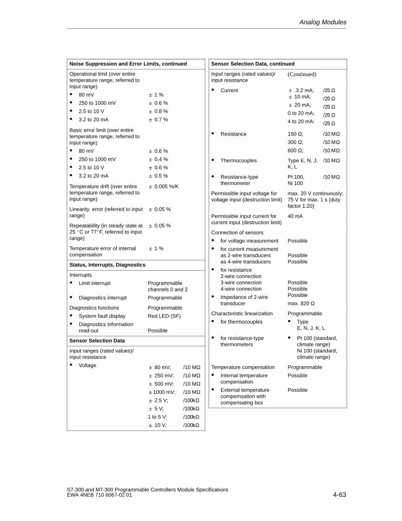
Analog Modules
4-63S7-300 and M7-300 Programmable Controllers Module SpecificationsEWA 4NEB 710 6067-02 01
Noise Suppression and Error Limits, continued
Operational limit (over entiretemperature range, referred toinput range)
80 mV
250 to 1000 mV
2.5 to 10 V
3.2 to 20 mA
1 %
0.6 %
0.8 %
0.7 %
Basic error limit (over entiretemperature range, referred toinput range)
80 mV
250 to 1000 mV
2.5 to 10 V
3.2 to 20 mA
0.6 %
0.4 %
0.6 %
0.5 %
Temperature drift (over entiretemperature range, referred toinput range)
0.005 %/K
Linearity error (referred to inputrange)
0.05 %
Repeatability (in steady state at25 C or 77F, referred to inputrange)
0.05 %
Temperature error of internalcompensation
1 %
Status, Interrupts, Diagnostics
Interrupts
Limit interrupt
Diagnostics interrupt
Programmablechannels 0 and 2
Programmable
Diagnostics functions
System fault display
Diagnostics informationread-out
Programmable
Red LED (SF)
Possible
Sensor Selection Data
Input ranges (rated values)/input resistance
Voltage 80 mV;
250 mV;
500 mV;
1000 mV;
2.5 V;
5 V;
1 to 5 V;
10 V;
/10 MΩ/10 MΩ/10 MΩ/10 MΩ/100kΩ/100kΩ/100kΩ/100kΩ
Sensor Selection Data, continued
Input ranges (rated values)/input resistance
(Continued)
Current .3.2 mA; 10 mA;
20 mA;
0 to 20 mA;
4 to 20 mA:
/25 Ω/25 Ω/25 Ω/25 Ω/25 Ω
Resistance 150 Ω;
300 Ω;
600 Ω;
/10 ΜΩ/10 ΜΩ/10 ΜΩ
Thermocouples Type E, N, J,K, L
/10 ΜΩ
Resistance-typethermometer
Pt 100,Ni 100
/10 ΜΩ
Permissible input voltage forvoltage input (destruction limit)
max. 20 V continuously;75 V for max. 1 s (dutyfactor 1:20)
Permissible input current forcurrent input (destruction limit)
40 mA
Connection of sensors
for voltage measurement
for current measurementas 2-wire transducersas 4-wire transducers
for resistance2-wire connection3-wire connection4-wire connection
Impedance of 2-wiretransducer
Possible
PossiblePossible
PossiblePossiblePossible
max. 820 Ω
Characteristic linearization
for thermocouples
Programmable
TypeE, N, J, K, L
for resistance-typethermometers
Pt 100 (standard,climate range)Ni 100 (standard,climate range)
Temperature compensation
Internal temperaturecompensation
External temperaturecompernsation withcompensating box
Programmable
Possible
Possible
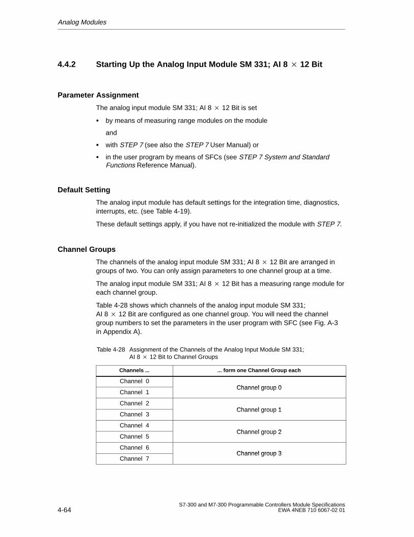
Analog Modules
4-64S7-300 and M7-300 Programmable Controllers Module Specifications
EWA 4NEB 710 6067-02 01
4.4.2 Starting Up the Analog Input Module SM 331; AI 8 12 Bit
Parameter Assignment
The analog input module SM 331; AI 8 12 Bit is set
by means of measuring range modules on the module
and
with STEP 7 (see also the STEP 7 User Manual) or
in the user program by means of SFCs (see STEP 7 System and StandardFunctions Reference Manual).
Default Setting
The analog input module has default settings for the integration time, diagnostics,interrupts, etc. (see Table 4-19).
These default settings apply, if you have not re-initialized the module with STEP 7.
Channel Groups
The channels of the analog input module SM 331; AI 8 12 Bit are arranged ingroups of two. You can only assign parameters to one channel group at a time.
The analog input module SM 331; AI 8 12 Bit has a measuring range module foreach channel group.
Table 4-28 shows which channels of the analog input module SM 331;AI 8 12 Bit are configured as one channel group. You will need the channelgroup numbers to set the parameters in the user program with SFC (see Fig. A-3in Appendix A).
Table 4-28 Assignment of the Channels of the Analog Input Module SM 331; AI 8 12 Bit to Channel Groups
Channels ... ... form one Channel Group each
Channel 0Channel group 0
Channel 1Channel group 0
Channel 2Channel group 1
Channel 3Channel group 1
Channel 4Channel group 2
Channel 5Channel group 2
Channel 6Channel group 3
Channel 7Channel group 3
Analog Modules
4-65S7-300 and M7-300 Programmable Controllers Module SpecificationsEWA 4NEB 710 6067-02 01
Resistance Measurement
If you use the resistance measurement method, there is only one channel perchannel group. The “2nd” channel of each group is used for current injection (IC).
The measured value is obtained by accessing the “1st” channel of the group. The“2nd” channel of the group has the default carry value “7FFFH”.
Unused Input Channels
You must short-circuit unused channels of the analog input module SM 331;AI 8 12 Bit and you should connect them to MANA. In this way, you obtain anoptimum interference immunity for the analog input module. Also deactivate theunused channels using STEP 7 (see Section 4.3.4), in order to reduce themodule’s cycle time.
If you do not use the COMP input, you must short-circuit it also.
Since configured inputs can remain unused, because of the channel groupgeneration, you should note the following points for these inputs:
Measuring range 1 to 5 V: Connect the unused input in parallel with a usedinput of the same channel group.
Current measurement, 2-wire transducer: There are two ways to use thechannels:
a) Leave the unused input open and do not enable diagnostics for thischannel group. If diagnostics is enabled, the analog module triggers adiagnostics interrupt once and the group fault LED of the analog module flashes.
b) Connect a 1.5 to 3.3 k resistance to the unused input. You may thenenable diagnostics for this channel group.
Current measurement 4 to 20 mA, 4-wire transducer: Connect the unused inputin series with an input of the same channel group.
Special Feature of De-Activated Input Channels
If you de-activate all input channels and enable diagnostics when parameterizingthe analog input module SM 331; AI 8 12 Bit, the analog input module does notindicate that the “external auxiliary voltage” is missing.
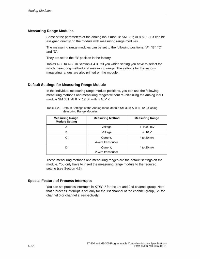
Analog Modules
4-66S7-300 and M7-300 Programmable Controllers Module Specifications
EWA 4NEB 710 6067-02 01
Measuring Range Modules
Some of the parameters of the analog input module SM 331; AI 8 12 Bit can beassigned directly on the module with measuring range modules.
The measuring range modules can be set to the following positions: “A”, “B”, “C”and “D”.
They are set to the “B” position in the factory.
Tables 4-30 to 4-33 in Section 4.4.3. tell you which setting you have to select forwhich measuring method and measuring range. The settings for the variousmeasuring ranges are also printed on the module.
Default Settings for Measuring Range Module
In the individual measuring range module positions, you can use the followingmeasuring methods and measuring ranges without re-initializing the analog inputmodule SM 331; AI 8 12 Bit with STEP 7:
Table 4-29 Default Settings of the Analog Input Module SM 331; AI 8 12 Bit UsingMeasuring Range Modules
Measuring Range Module Setting
Measuring Method Measuring Range
A Voltage 1000 mV
B Voltage 10 V
C Current,
4-wire transducer
4 to 20 mA
D Current,
2-wire transducer
4 to 20 mA
These measuring methods and measuring ranges are the default settings on themodule. You only have to insert the measuring range module to the requiredsetting (see Section 4.3).
Special Feature of Process Interrupts
You can set process interrupts in STEP 7 for the 1st and 2nd channel group. Notethat a process interrupt is set only for the 1st channel of the channel group, i.e. forchannel 0 or channel 2, respectively.
Analog Modules
4-67S7-300 and M7-300 Programmable Controllers Module SpecificationsEWA 4NEB 710 6067-02 01
4.4.3 Measuring Methods and Measuring Ranges of the Analog InputModule SM 331; AI 8 12 Bit
Measuring Methods
You can set the following measuring methods on the analog input module SM 331;AI 8 12 Bit:
Voltage measurement
Current measurement
Resistance measurement
Temperature measurement
Use the S7 Configuration STEP 7 tool and the measuring range modules on theanalog input module to make the necessary settings (see Section 4.3.4).
Measuring Ranges
Tables 4-30 to 4-33 list the measuring ranges you can use with the analog inputmodule. Use STEP 7 and the measuring range modules on the analog inputmodule to select the desired measuring ranges (see Section 4.3.4). Tables 4-30 to4-33 also show the necessary settings of the measuring range modules.
Wire-Break Check
With the measuring range 4 to 20 mA and
activated wire-break check, the analog input module enters a wire break in thediagnostics if the current value falls below 3.6 mA. If you have enableddiagnostics interrupt during configuration, the analog input module additionallytriggers a diagnostics interrupt.If no diagnostics interrupt has been enabled, the illuminated SF display is theonly indicator for the wire break and you must evaluate the diagnostics bytes inthe user program.
non-activated wire-break check, the analog input module triggers a diagnosticsinterrupt when the underflow has been reached.

Analog Modules
4-68S7-300 and M7-300 Programmable Controllers Module Specifications
EWA 4NEB 710 6067-02 01
Measuring Ranges for Voltage Measurements
Table 4-30 shows all of the measuring ranges or the sensor type for voltagemeasurements, as well as the relevant measuring range module settings.
Table 4-30 Measuring Ranges for Voltage Measurement
Measuring MethodSelected
Description Measuring Range(Type of Sensor)
Measuring RangeModule Setting
Voltage You will find the digitized analogvalues in Section 4.1.2, Tables 4-4and 4-6 in the voltage measuringrange.
+/– 80 mV
+/– 250 mV
+/– 500 mV
+/– 1000 mV
A
+/– 2,5 V
+/– 5 V
1 to 5 V
+/– 10 V
B
Thermocouples +internal compensation(thermovoltagemeasurement)
You will find the digitized analogvalues in Section 4.1.2, Table 4-4in the voltage measuringrange 80 mV.
Typ N [NiCrSi-NiSi]TypeE [NiCr-CuNi]Type J [Fe-CuNi]Type K [NiCr-Ni]Type L [Fe-CuNi]
A
Thermocouples +external compensation(thermovoltagemeasurement)
You will find the digitized analogvalues in Section 4.1.2, Table 4-4in the voltage measuringrange 80 mV.
Type N [NiCrSi-NiSi]Type E [NiCr-CuNi]Type J [Fe-CuNi]Type K [NiCr-Ni]Type L [Fe-CuNi]
A
Measuring Ranges for Current Measurement
Table 4-31 lists all of the measuring ranges for current measurement with 2-wireand 4-wire transducers, as well as the relevant measuring rangemodule settings.
Table 4-31 Measuring Ranges for 2-Wire and 4-Wire Transducers
Measuring MethodSelected
Description Measuring Range Measuring RangeModule Setting
2-wire transducers You will find the digitized analogvalues in Section 4.1.2, Table 4-6in the current measuring range.
4 to 20 mA D
4-wire transducers You will find the digitized analogvalues in Section 4.1.2, Table 4-5and 4-6 in the current measuringrange.
+/– 3.2 mA
+/– 10 mA
0 to 20 mA
4 to 20 mA
+/– 20 mA
C
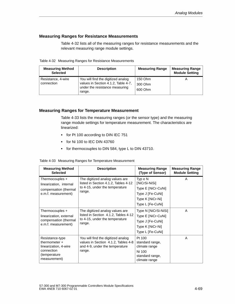
Analog Modules
4-69S7-300 and M7-300 Programmable Controllers Module SpecificationsEWA 4NEB 710 6067-02 01
Measuring Ranges for Resistance Measurements
Table 4-32 lists all of the measuring ranges for resistance measurements and therelevant measuring range module settings.
Table 4-32 Measuring Ranges for Resistance Measurements
Measuring MethodSelected
Description Measuring Range Measuring RangeModule Setting
Resistance, 4-wireconnection
You will find the digitized analogvalues in Section 4.1.2, Table 4-7,under the resistance measuringrange.
150 Ohm
300 Ohm
600 Ohm
A
Measuring Ranges for Temperature Measurement
Table 4-33 lists the measuring ranges (or the sensor type) and the measuringrange module settings for temperature measurement. The characteristics arelinearized:
for Pt 100 according to DIN IEC 751
for Ni 100 to IEC DIN 43760
for thermocouples to DIN 584, type L to DIN 43710.
Table 4-33 Measuring Ranges for Temperature Measurement
Measuring MethodSelected
Description Measuring Range(Type of Sensor)
Measuring RangeModule Setting
Thermocouples +
linearization, internal
compensation (thermale.m.f. measurement)
The digitized analog values arelisted in Section 4.1.2, Tables 4-12to 4-15, under the temperaturerange.
Typ e N[NiCrSi-NiSi]Type E [NiCr-CuNi]Type J [Fe-CuNi]Type K [NiCr-Ni]Type L [Fe-CuNi]
A
Thermocouples +
linearization, externalcompensation (thermale.m.f. measurement)
The digitized analog values arelisted in Section 4.1.2, Tables 4-12to 4-15, under the temperaturerange.
Type N [NiCrSi-NiSi]Type E [NiCr-CuNi]Type J [Fe-CuNi]Type K [NiCr-Ni]Type L [Fe-CuNi]
A
Resistance-typethermometer +linearization, 4-wireconnection(temperaturemeasurement)
You will find the digitized analogvalues in Section 4.1.2, Tables 4-8and 4-9, under the temperaturerange.
Pt 100standard range,climate range
Ni 100standard range,climate range
A
Analog Modules
4-70S7-300 and M7-300 Programmable Controllers Module Specifications
EWA 4NEB 710 6067-02 01
4.5 Analog Input Module SM 331; AI 8 16 Bit
Order No.
6ES7 331-7NF00-0AB0
Characteristic Features
The analog input module SM 331; AI 8 16 Bit has the following characteristicfeatures:
8 inputs in 4 channel groups
Measured-value resolution 15 Bit + sign (independent of integration time)
Fast update mode for individually enabled channel groups 0 or 1
Measurement mode selectable per channel group:
– Voltage
– Current
Arbitrary measuring range and filter/update rate selection per channel group
Programmable diagnostics
Programmable diagnostic interrupt
Two channels with limit monitoring
Programmable limit interrupt
Galvanic isolation to CPU
Permissible common mode voltage between channels of 50 VDC maximum
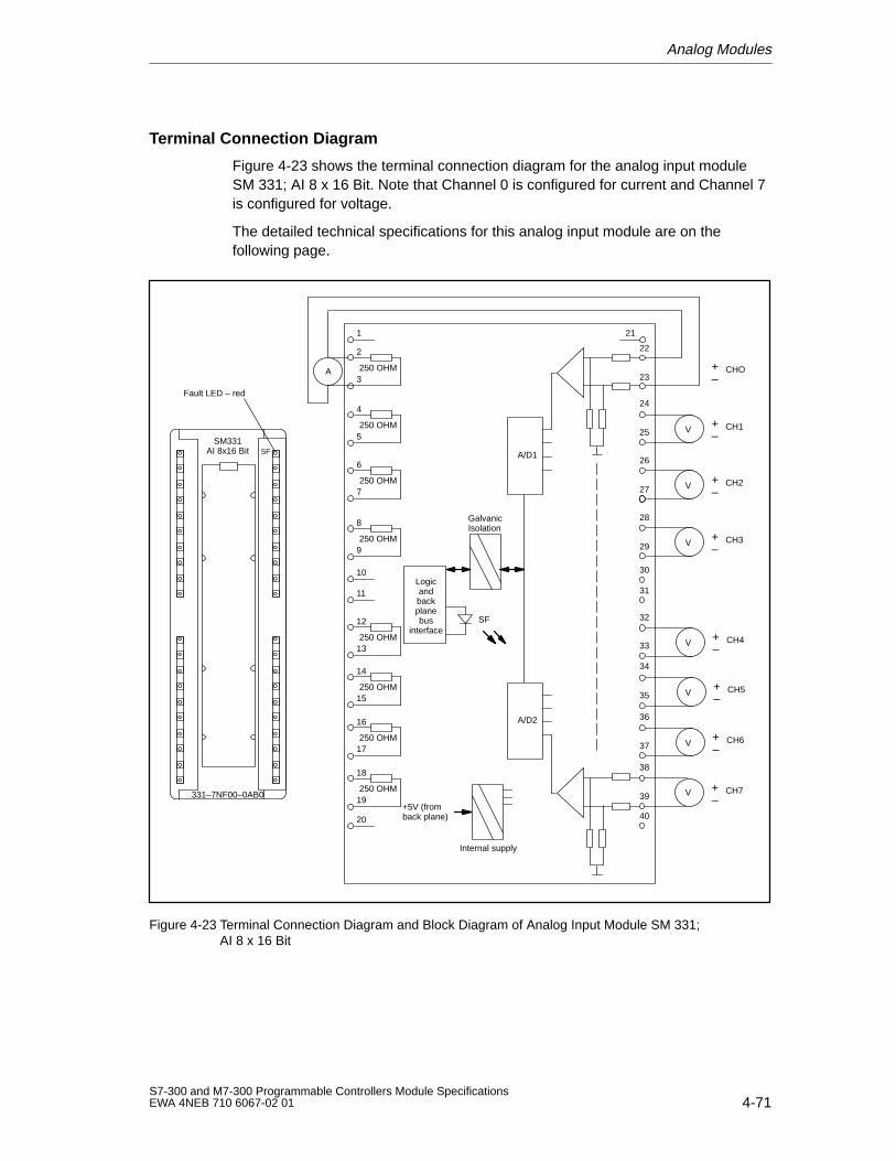
Analog Modules
4-71S7-300 and M7-300 Programmable Controllers Module SpecificationsEWA 4NEB 710 6067-02 01
Terminal Connection Diagram
Figure 4-23 shows the terminal connection diagram for the analog input moduleSM 331; AI 8 x 16 Bit. Note that Channel 0 is configured for current and Channel 7is configured for voltage.
The detailed technical specifications for this analog input module are on thefollowing page.
2
SM331AI 8x16 Bit
331–7NF00–0AB0
20
1
3250 OHM
4
5250 OHM
6
7250 OHM
8
9250 OHM
10
11
12
13250 OHM
14
15250 OHM
16
17250 OHM
18
19250 OHM
A +–
CHO
V +–
CH1
V +–
CH2
V +–
CH3
V +–
CH4
V +–
CH5
V +–
CH6
V +–
CH7
21
29
26
27
24
25
22
23
33
32
35
34
37
36
39
38
28
40
31
30
A/D1
A/D2
Logicandbackplanebus
interfaceSF
Internal supply
GalvanicIsolation
+5V (fromback plane)
SF
Fault LED – red
Figure 4-23 Terminal Connection Diagram and Block Diagram of Analog Input Module SM 331;AI 8 x 16 Bit
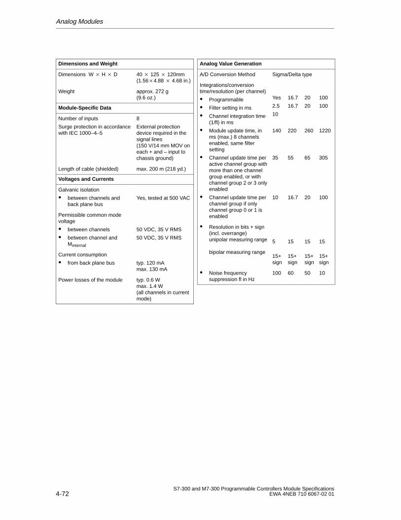
Analog Modules
4-72S7-300 and M7-300 Programmable Controllers Module Specifications
EWA 4NEB 710 6067-02 01
Dimensions and W eight
Dimensions W H D 40 125 120mm(1.564.88 4.68 in.)
Weight approx. 272 g(9.6 oz.)
Module-Specific Data
Number of inputs
Surge protection in accordancewith IEC 1000–4–5
8
External protectiondevice required in thesignal lines (150 V/14 mm MOV oneach + and – input tochassis ground)
Length of cable (shielded) max. 200 m (218 yd.)
Voltages and Currents
Galvanic isolation
between channels andback plane bus
Yes, tested at 500 VAC
Permissible common modevoltage
between channels
between channel andMinternal
50 VDC, 35 V RMS
50 VDC, 35 V RMS
Current consumption
from back plane bus typ. 120 mAmax. 130 mA
Power losses of the module typ. 0.6 Wmax. 1.4 W (all channels in currentmode)
Analog V alue Generation
A/D Conversion Method Sigma/Delta type
Integrations/conversiontime/resolution (per channel)
Programmable
Filter setting in ms
Channel integration time(1/fl) in ms
Module update time, inms (max.) 8 channelsenabled, same filtersetting
Channel update time peractive channel group withmore than one channelgroup enabled, or withchannel group 2 or 3 onlyenabled
Channel update time perchannel group if onlychannel group 0 or 1 isenabled
Yes
2.5
10
140
35
10
16.7
16.7
220
55
16.7
20
20
260
65
20
100
100
1220
305
100
Resolution in bits + sign(incl. overrange)unipolar measuring range
bipolar measuring range
5
15+sign
15
15+sign
15
15+sign
15
15+sign
Noise frequencysuppression fl in Hz
100 60 50 10
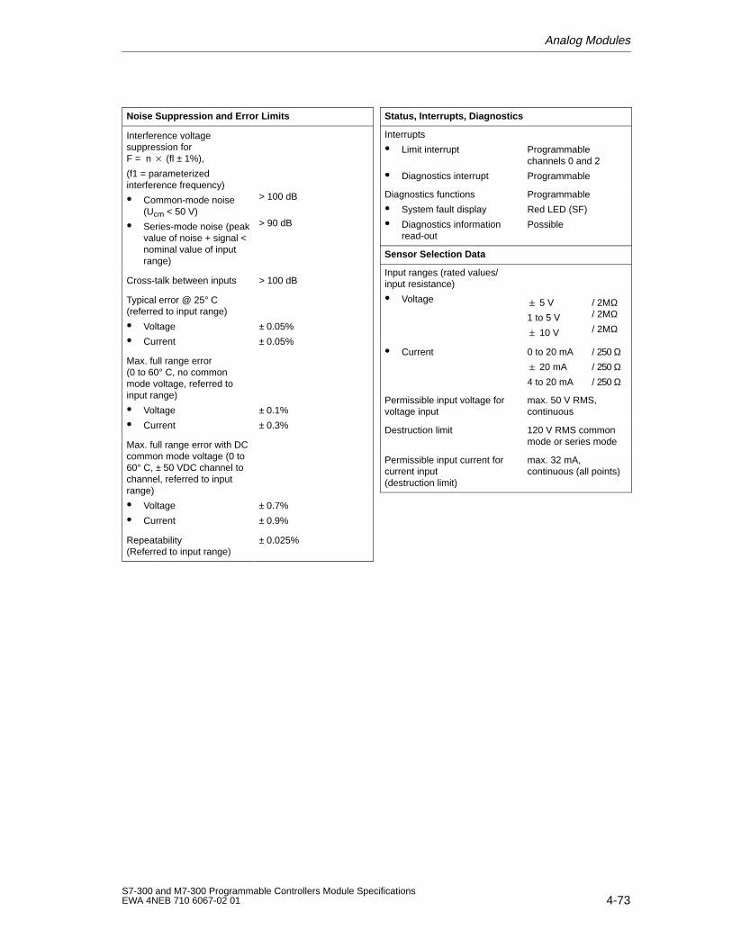
Analog Modules
4-73S7-300 and M7-300 Programmable Controllers Module SpecificationsEWA 4NEB 710 6067-02 01
Noise Suppression and Error Limits
Interference voltagesuppression for F = n (fl ± 1%),
(f1 = parameterizedinterference frequency)
Common-mode noise(Ucm < 50 V)
Series-mode noise (peakvalue of noise + signal <nominal value of inputrange)
> 100 dB
> 90 dB
Cross-talk between inputs > 100 dB
Typical error @ 25° C(referred to input range)
Voltage
Current
± 0.05%
± 0.05%
Max. full range error(0 to 60° C, no commonmode voltage, referred toinput range)
Voltage
Current
± 0.1%
± 0.3%
Max. full range error with DCcommon mode voltage (0 to60° C, ± 50 VDC channel tochannel, referred to inputrange)
Voltage
Current
± 0.7%
± 0.9%
Repeatability (Referred to input range)
± 0.025%
Status, Interrupts, Diagnostics
Interrupts
Limit interrupt
Diagnostics interrupt
Programmablechannels 0 and 2
Programmable
Diagnostics functions
System fault display
Diagnostics informationread-out
Programmable
Red LED (SF)
Possible
Sensor Selection Data
Input ranges (rated values/input resistance)
Voltage 5 V
1 to 5 V
10 V
/ 2MΩ/ 2MΩ/ 2MΩ
Current 0 to 20 mA
20 mA
4 to 20 mA
/ 250 Ω/ 250 Ω/ 250 Ω
Permissible input voltage forvoltage input
max. 50 V RMS,continuous
Destruction limit 120 V RMS commonmode or series mode
Permissible input current forcurrent input (destruction limit)
max. 32 mA,continuous (all points)
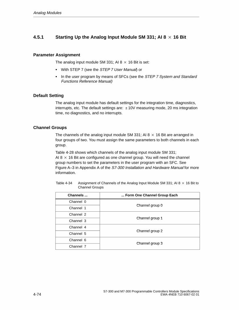
Analog Modules
4-74S7-300 and M7-300 Programmable Controllers Module Specifications
EWA 4NEB 710 6067-02 01
4.5.1 Starting Up the Analog Input Module SM 331; AI 8 16 Bit
Parameter Assignment
The analog input module SM 331; AI 8 16 Bit is set:
With STEP 7 (see the STEP 7 User Manual) or
In the user program by means of SFCs (see the STEP 7 System and StandardFunctions Reference Manual)
Default Setting
The analog input module has default settings for the integration time, diagnostics,interrupts, etc. The default settings are: ± 10V measuring mode, 20 ms integrationtime, no diagnostics, and no interrupts.
Channel Groups
The channels of the analog input module SM 331; AI 8 16 Bit are arranged infour groups of two. You must assign the same parameters to both channels in eachgroup.
Table 4-28 shows which channels of the analog input module SM 331;AI 8 16 Bit are configured as one channel group. You will need the channelgroup numbers to set the parameters in the user program with an SFC. SeeFigure A–3 in Appendix A of the S7-300 Installation and Hardware Manual for moreinformation.
Table 4-34 Assignment of Channels of the Analog Input Module SM 331; AI 8 16 Bit toChannel Groups
Channels ... ... Form One Channel Group Each
Channel 0Channel group 0
Channel 1Channel group 0
Channel 2Channel group 1
Channel 3Channel group 1
Channel 4Channel group 2
Channel 5Channel group 2
Channel 6Channel group 3
Channel 7Channel group 3
Analog Modules
4-75S7-300 and M7-300 Programmable Controllers Module SpecificationsEWA 4NEB 710 6067-02 01
Unused Input Channels
Unused channels of the analog input module SM331; AI 8 x 16 Bit should bedeactivated using STEP 7 in order to reduce the module’s cycle time. SeeSection 4.3.4 of the S7-300 Installation and Hardware manual for moreinformation.
Since configured inputs can remain unused because of the channel groupgeneration, you should make the following preparation for these inputs ifdiagnostics on the used channels are enabled.
Measuring range 1 to 5 V: Connect the unused input in parallel with a usedinput of the same channel group.
Current measurement 4 to 20 mA: Connect the unused input in series with aninput of the same channel group. Ensure that a current sense resistor isconnected for each active and unused channel.
Other ranges: Short the positive to the negative input of the channel.
Current Measurement Mode
Current measurements are made by paralleling a channel’s voltage input terminalswith its respective current sense resistor. This is accomplished by jumpering thechannels input terminals to the adjacent terminals on the field connector. Forexample, to configure channel 0 for current mode, you must jumper terminal 22 to2 and terminal 23 to 3.
The channel being configured for current measurements must be paired with thesense resistor connected to the channel’s adjacent terminals in order to achievethe specified accuracy.
High Speed Update Mode
The high speed update mode is only available when two channels are enabled onchannel group 0 or 1.
The module enters the high speed update mode if either channel group 0 orchannel group 1 (not both) is enabled. In the high speed update mode, updates forthe two channels in the group occur three times faster than with multiple channelgroups enabled. For example, if channels 0 and 1 are enabled with 2.5 ms filtering,data updates for both channels will be available to the PLC every 10 msec. (Forother filter settings, the filter setting equals the update rate.)
Special Feature of Process Interrupts
You can set process interrupts in STEP 7 for the first and second channel group.Note that a process interrupt is set only for the first channel of the channel group,that is, for channel 0 or channel 2 respectively.
Analog Modules
4-76S7-300 and M7-300 Programmable Controllers Module Specifications
EWA 4NEB 710 6067-02 01
4.5.2 Measuring Methods and Measuring Ranges of the Analog InputModule SM 331; AI 8 16 Bit
Measuring Methods
You can set the following measuring methods on the analog input module SM 331;AI 8 16 Bit:
Voltage measurement
Current measurement
Use the STEP 7 tool on the analog input module to make the necessary settings.See Section 4.3.4 of the S7-300 Installation and Hardware Manual for moreinformation about these settings.
Measuring Ranges
Table 4-35 lists the measuring ranges you can use with the analog input module.Use STEP 7 to select the desired measuring ranges.
Common Mode Voltage
The analog input module SM 331; AI 8 x 16 Bit can make measurements in thepresence of AC or DC common mode voltage.
For AC common mode voltages at multiples of the filter frequency setting, therejection is accomplished by the integration period of the A/D converter and by thecommon mode rejection of the input amplifiers. For AC common mode voltages< 35 VRMS, the rejection ratio of > 100 dB results in negligible measurement error.
For DC common mode voltages, only the rejection of the input amplifier stage isavailable to minimize the effect of the common mode voltage. Therefore, someaccuracy degradation occurs in proportion to the common mode voltage. The worstcase error occurs with 50 VDC between one channel and the other sevenchannels. The calculated worst case error is 0.7% from 0 to 60 degrees C, andmeasured error is typically ≤ 0.1% @ 25 degrees C.
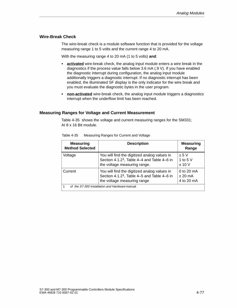
Analog Modules
4-77S7-300 and M7-300 Programmable Controllers Module SpecificationsEWA 4NEB 710 6067-02 01
Wire-Break Check
The wire-break check is a module software function that is provided for the voltagemeasuring range 1 to 5 volts and the current range 4 to 20 mA.
With the measuring range 4 to 20 mA (1 to 5 volts) and :
activated wire-break check, the analog input module enters a wire break in thediagnostics if the process value falls below 3.6 mA (.9 V). If you have enabledthe diagnostic interrupt during configuration, the analog input moduleadditionally triggers a diagnostic interrupt. If no diagnostic interrupt has beenenabled, the illuminated SF display is the only indicator for the wire break andyou must evaluate the diagnostic bytes in the user program.
non-activated wire-break check, the analog input module triggers a diagnosticsinterrupt when the underflow limit has been reached.
Measuring Ranges for Voltage and Current Measurement
Table 4-35 shows the voltage and current measuring ranges for the SM331; AI 8 x 16 Bit module.
Table 4-35 Measuring Ranges for Current and Voltage
MeasuringMethod Selected
Description MeasuringRange
Voltage You will find the digitized analog values inSection 4.1.21, Table 4–4 and Table 4–6 inthe voltage measuring range.
± 5 V1 to 5 V± 10 V
Current You will find the digitized analog values inSection 4.1.21, Table 4–5 and Table 4–6 inthe voltage measuring range
0 to 20 mA± 20 mA4 to 20 mA
1 of the S7-300 Installation and Hardware manual
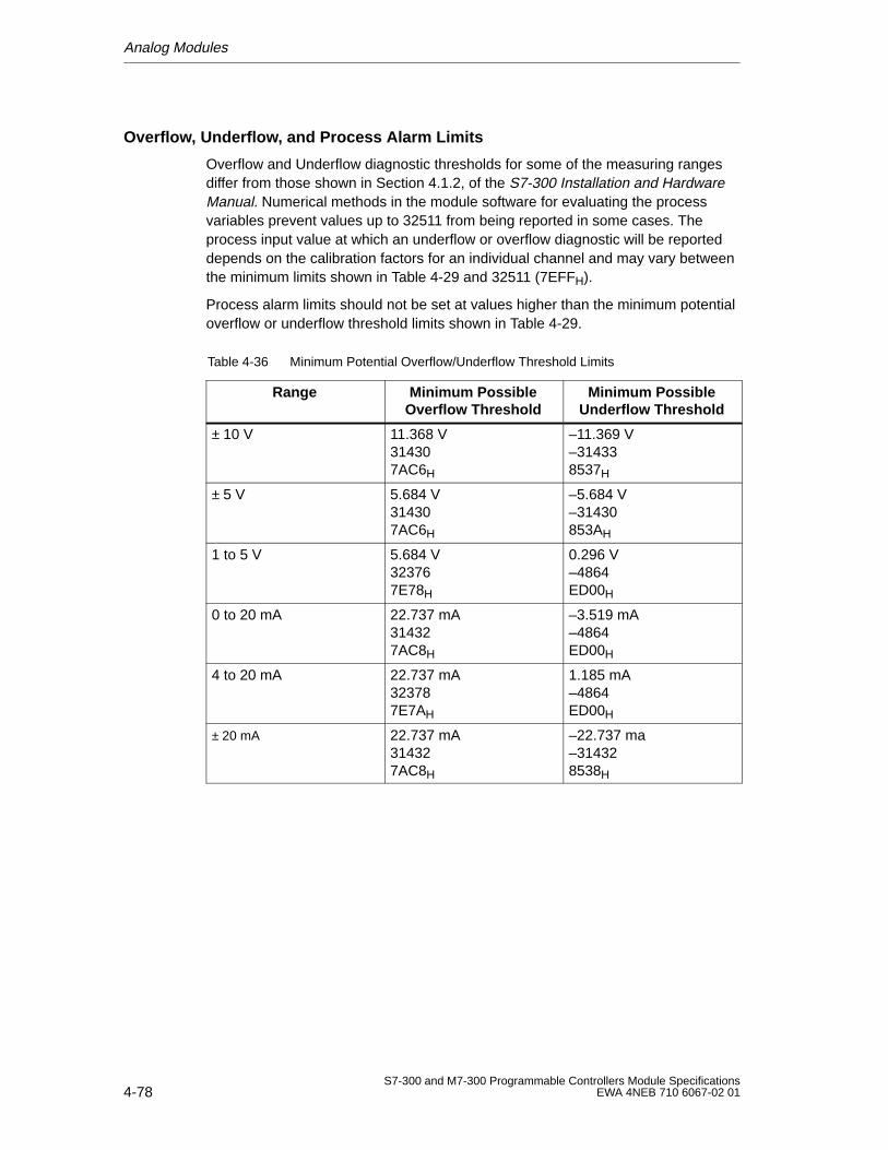
Analog Modules
4-78S7-300 and M7-300 Programmable Controllers Module Specifications
EWA 4NEB 710 6067-02 01
Overflow, Underflow, and Process Alarm Limits
Overflow and Underflow diagnostic thresholds for some of the measuring rangesdiffer from those shown in Section 4.1.2, of the S7-300 Installation and HardwareManual. Numerical methods in the module software for evaluating the processvariables prevent values up to 32511 from being reported in some cases. Theprocess input value at which an underflow or overflow diagnostic will be reporteddepends on the calibration factors for an individual channel and may vary betweenthe minimum limits shown in Table 4-29 and 32511 (7EFFH).
Process alarm limits should not be set at values higher than the minimum potentialoverflow or underflow threshold limits shown in Table 4-29.
Table 4-36 Minimum Potential Overflow/Underflow Threshold Limits
Range Minimum PossibleOverflow Threshold
Minimum PossibleUnderflow Threshold
± 10 V 11.368 V314307AC6H
–11.369 V–314338537H
± 5 V 5.684 V314307AC6H
–5.684 V–31430853AH
1 to 5 V 5.684 V323767E78H
0.296 V–4864ED00H
0 to 20 mA 22.737 mA314327AC8H
–3.519 mA–4864ED00H
4 to 20 mA 22.737 mA323787E7AH
1.185 mA–4864ED00H
± 20 mA 22.737 mA314327AC8H
–22.737 ma–314328538H
Analog Modules
4-79S7-300 and M7-300 Programmable Controllers Module SpecificationsEWA 4NEB 710 6067-02 01
4.6 Analog Input Module SM 331; AI 2 12 Bit
In this Section
In this section, you will find information on:
The characteristics of the analog input module SM 331; AI 2 12 Bit
The technical specifications of the analog input module SM 331; AI 2 12 Bit
You will also learn:
How to start up the analog input module SM 331; AI 2 12 Bit
Which measuring ranges the analog input module SM 331; AI 2 12 Bit has
Which parameters can be used to influence the characteristics of the analoginput module SM 331; AI 2 12 Bit
Analog Modules
4-80S7-300 and M7-300 Programmable Controllers Module Specifications
EWA 4NEB 710 6067-02 01
4.6.1 Characteristic Features and Technical Specifications of theAnalog Input Module SM 331; AI 2 12 Bit
Order No.
6ES7 331-7KB01-0AB0
Characteristic Features
The analog input module SM 331; AI 2 12 Bit has the following characteristicfeatures:
Two inputs in one channel group
Measured-value resolution (depending on the integration time set)
– 9 bits + sign
– 12 bits + sign
– 14 bits + sign
Measuring method selectable per channel group:
– Voltage
– Current
– Resistance
– Temperature
Arbitrary measuring range selection per channel group
Programmable diagnostics
Programmable diagnostic interrupt
One channel with limit monitoring
Programmable limit interrupt
Galvanic isolation to CPU
Galvanic isolation to load voltage (not for 2-wire transducer)
Resolution
The resolution of the measured value is a direct function of the integration timeselected. In other words the longer the integration time for an analog input channel,the more accurate the resolution of the measured value will be (see technicalspecifications of analog input module and Table 4-3).
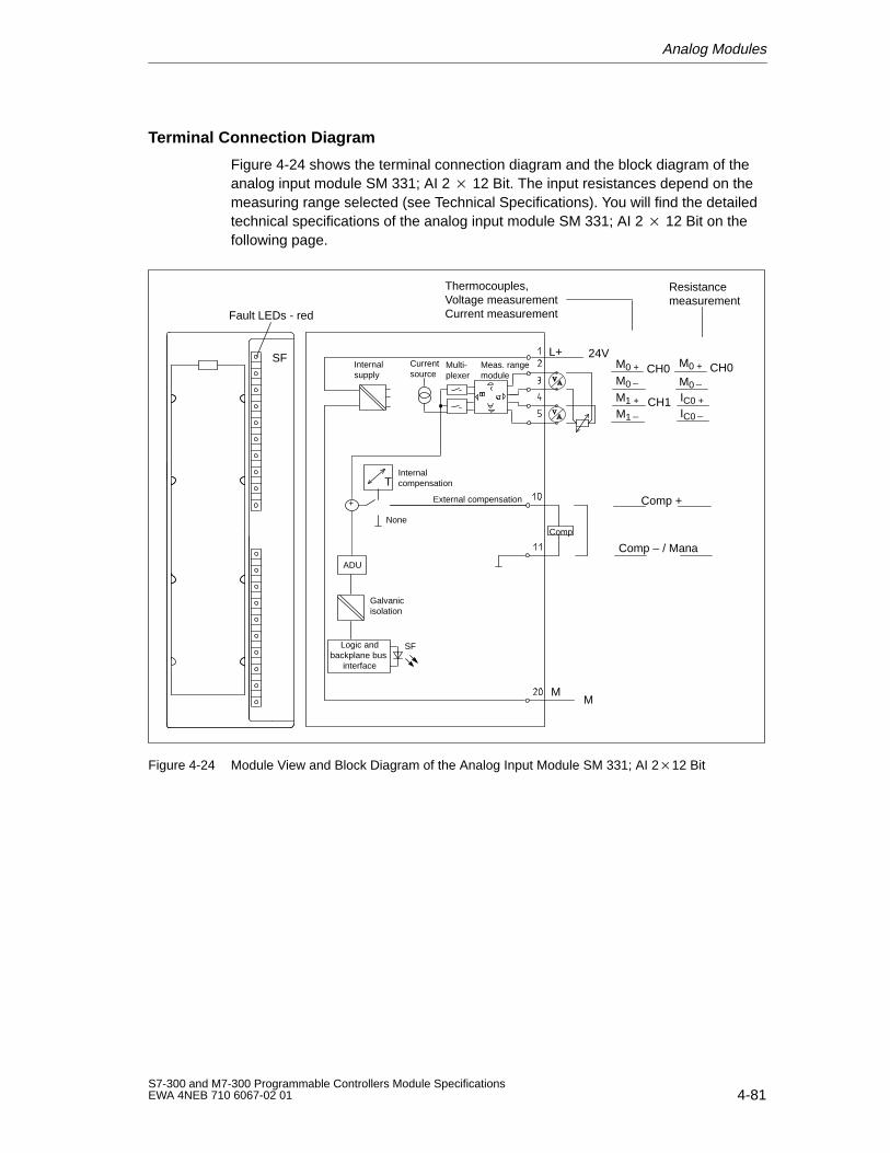
Analog Modules
4-81S7-300 and M7-300 Programmable Controllers Module SpecificationsEWA 4NEB 710 6067-02 01
Terminal Connection Diagram
Figure 4-24 shows the terminal connection diagram and the block diagram of theanalog input module SM 331; AI 2 12 Bit. The input resistances depend on themeasuring range selected (see Technical Specifications). You will find the detailedtechnical specifications of the analog input module SM 331; AI 2 12 Bit on thefollowing page.
Fault LEDs - red
Thermocouples,Voltage measurementCurrent measurement
Resistancemeasurement
M0 +
M0
M1 +
SFInternal supply
L+Current source
Multi-plexer
Meas. rangemodule
None
ADU
Galvanicisolation
Logic andbackplane bus
interface
SF
+
Internalcompensation
CH0 M0 + CH0M0IC0 +CH1
M1 IC0
24V
Comp – / Mana
Comp +External compensation
Comp
MM
T
Figure 4-24 Module View and Block Diagram of the Analog Input Module SM 331; AI 212 Bit
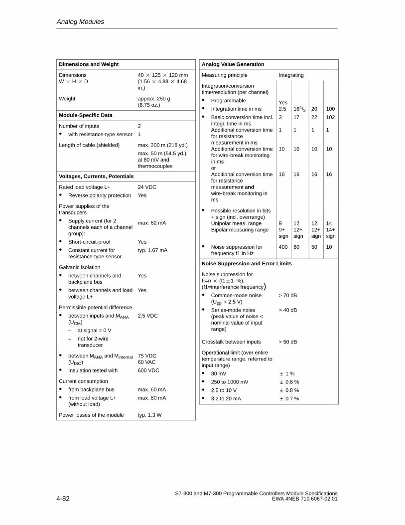
Analog Modules
4-82S7-300 and M7-300 Programmable Controllers Module Specifications
EWA 4NEB 710 6067-02 01
Dimensions and W eight
Dimensions W H D
40 125 120 mm(1.56 4.88 4.68in.)
Weight approx. 250 g(8.75 oz.)
Module-Specific Data
Number of inputs
with resistance-type sensor
2
1
Length of cable (shielded) max. 200 m (218 yd.)
max. 50 m (54.5 yd.)at 80 mV andthermocouples
Voltages, Currents, Potentials
Rated load voltage L+
Reverse polarity protection
24 VDC
Yes
Power supplies of thetransducers
Supply current (for 2channels each of a channelgroup):
Short-circuit-proof
Constant current forresistance-type sensor
max: 62 mA
Yes
typ. 1.67 mA
Galvanic isolation
between channels andbackplane bus
between channels and loadvoltage L+
Yes
Yes
Permissible potential difference
between inputs and MANA(UCM)
– at signal = 0 V
– not for 2-wiretransducer
2.5 VDC
between MANA and Minternal(UISO)
Insulation tested with
75 VDC60 VAC
600 VDC
Current consumption
from backplane bus
from load voltage L+(without load)
max. 60 mA
max. 80 mA
Power losses of the module typ. 1.3 W
Analog V alue Generation
Measuring principle Integrating
Integration/conversiontime/resolution (per channel)
Programmable
Integration time in ms
Basic conversion time incl.integr. time in msAdditional conversion timefor resistancemeasurement in msAdditional conversion timefor wire-break monitoringin msorAdditional conversion timefor resistancemeasurement andwire-break monitoring inms
Yes2.5
3
1
10
16
162/317
1
10
16
20
22
1
10
16
100
102
1
10
16
Possible resolution in bits+ sign (incl. overrange)Unipolar meas. rangeBipolar measuring range
99+sign
1212+sign
1212+sign
1414+sign
Noise suppression forfrequency f1 in Hz
400 60 50 10
Noise Suppression and Error Limits
Noise suppression forF=n (f11 %),(f1=interference frequency) Common-mode noise
(Upp 2.5 V)
Series-mode noise(peak value of noise <nominal value of inputrange)
> 70 dB
> 40 dB
Crosstalk between inputs > 50 dB
Operational limit (over entiretemperature range, referred toinput range)
80 mV
250 to 1000 mV
2.5 to 10 V
3.2 to 20 mA
1 %
0.6 %
0.8 %
0.7 %
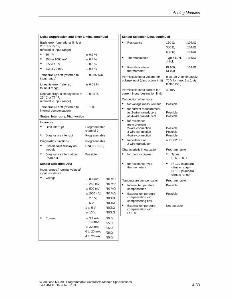
Analog Modules
4-83S7-300 and M7-300 Programmable Controllers Module SpecificationsEWA 4NEB 710 6067-02 01
Noise Suppression and Error Limits, continued
Basic error (operational limit at25 °C or 77 °F,referred to input range)
80 mV
250 to 1000 mV
2.5 to 10 V
3.2 to 20 mA
0.6 %
0.4 %
0.6 %
0.5 %
Temperature drift (referred toinput range)
0.005 %/K
Linearity error (referredto input range)
0.05 %
Repeatability (in steady state at25 °C or 77 °F,referred to input range)
0.05 %
Temperature drift (referred tointernal compensation)
1 %
Status, Interrupts, Diagnostics
Interrupts
Limit interrupt
Diagnostics interrupt
Programmablechannel 0
Programmable
Diagnostics functions
System fault display onmodule
Diagnostics informationRead-out
Programmable
Red LED (SF)
Possible
Sensor Selection Data
Input ranges (nominal values)/input resistance
Voltage 80 mV;
250 mV;
500 mV;
1000 mV;
2.5 V;
5 V;
1 to 5 V;
10 V;
/10 MΩ/10 MΩ/10 MΩ/10 MΩ/100kΩ/100kΩ/100kΩ/100kΩ
Current 3.2 mA; 10 mA;
20 mA;
0 to 20 mA;
4 to 20 mA:
/25 Ω/25 Ω/25 Ω/25 Ω/25 Ω
Sensor Selection Data, continued
Resistance 150 Ω;
300 Ω;
600 Ω;
/10 ΜΩ/10 ΜΩ/10 ΜΩ
Thermocouples Types E, N,J, K,L
/10 ΜΩ
Resistance-typethermometer
Pt 100,Ni 100
/10 ΜΩ
Permissible input voltage forvoltage input (destruction limit)
max. 20 V continuously;75 V for max. 1 s (dutyfactor 1:20)
Permissible input current forcurrent input (destruction limit)
40 mA
Connection of sensors
for voltage measurement
for current measurementas 2-wire transducersas 4-wire transducers
for resistancemeasurement2-wire connection3-wire connection4-wire connection
Impedance of2-wire transducer
Possible
PossiblePossible
PossiblePossiblePossible
max. 820 Ω
Characteristic linearization
for thermocouples
Programmable
TypesE, N, J, K, L
for resistance-type thermometers
Pt 100 (standard,climate range)Ni 100 (standard,climate range)
Temperature compensation
Internal temperaturecompensation
External temperaturecompensation withcompensating box
External temperaturecompensation with Pt 100
Programmable
Possible
Possible
Not possible
Analog Modules
4-84S7-300 and M7-300 Programmable Controllers Module Specifications
EWA 4NEB 710 6067-02 01
4.6.2 Starting Up the Analog Input Module SM 331; AI 2 12 Bit
Parameter Assignment
You make the necessary settings of the analog input module SM 331;AI 2 12 Bit
by means of measuring range module on the module
and
with STEP 7 (see also the STEP 7 User Manual) or
in the user program by means of SFCs (see STEP 7 System and StandardFunctions Reference Manual).
Default Settings
The analog input module has default settings for the integration time, diagnostics,interrupts, etc. (see Table 4-19).
These default settings apply, if you have not re-initialized the module with STEP 7.
Channel Groups
The two channels of the analog input module SM 331; AI 2 12 Bit are combinedto a channel group. You can thus assign channel group parameters only to the twochannels.
The analog input module SM 331; AI 2 12 Bit has a measuring range module forthis channel group.
Resistance Measurement
If you use the resistance measurement method, the analog input module has onlyone channel. The “2nd” channel is used for current injection (IC).
The measured value is obtained by accessing the “1st” channel. The “2nd” channelhas the default carry value “7FFFH”.
Analog Modules
4-85S7-300 and M7-300 Programmable Controllers Module SpecificationsEWA 4NEB 710 6067-02 01
Unused Input Channels
You must short-circuit unused channels of the analog input module SM 331;AI 2 12 Bit and you should connect them to MANA. In this way, you obtain anoptimum interference immunity for the analog input module. Also deactivate theunused channels using STEP 7 (see Section 4.3.4), in order to reduce themodule’s cycle time.
If you do not use the COMP input, you must short-circuit it also.
Since configured inputs can remain unused, because of the channel groupgeneration, you should note the following points for these inputs:
Measuring range 1 to 5 V: Connect the unused input in parallel with a usedinput of the same channel group.
Current measurement, 2-wire transducer:
There are two ways to use the channels:
a) Leave the unused input open and do not enable diagnostics for this channelgroup. If diagnostics is enabled, the analog module triggers a diagnosticsinterrupt once and the group fault LED of the analog module flashes.
b) Provide a 1.5 to 3.3 k resistor on unused input. You may then enablediagnostics for this channel group.
Current measurement 4 to 20 mA, 4-wire transducer: Connect the unused inputin series with an input of the same channel group.
Measuring Range Module
Some of the parameters of the analog input module SM 331; AI 2 12 Bit can beassigned directly on the module with a measuring range module. The analog inputmodule is supplied with the measuring range module plugged in.
The measuring range modules can be set to the following positions: “A”, “B”, “C”and “D”.
They are set to the “B” position in the factory.
Tables 4-38 to 4-41 in Section 4.6.3 tell you which setting you have to select forwhich measuring method and measuring range. The settings for the variousmeasuring ranges are also printed on the module.
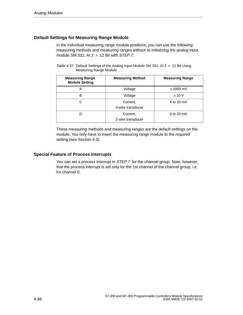
Analog Modules
4-86S7-300 and M7-300 Programmable Controllers Module Specifications
EWA 4NEB 710 6067-02 01
Default Settings for Measuring Range Module
In the individual measuring range module positions, you can use the followingmeasuring methods and measuring ranges without re-initializing the analog inputmodule SM 331; AI 2 12 Bit with STEP 7:
Table 4-37 Default Settings of the Analog Input Module SM 331; AI 2 12 Bit UsingMeasuring Range Module
Measuring Range Module Setting
Measuring Method Measuring Range
A Voltage 1000 mV
B Voltage 10 V
C Current,
4-wire transducer
4 to 20 mA
D Current,
2-wire transducer
4 to 20 mA
These measuring methods and measuring ranges are the default settings on themodule. You only have to insert the measuring range module to the requiredsetting (see Section 4.3).
Special Feature of Process Interrupts
You can set a process interrupt in STEP 7 for the channel group. Note, however,that the process interrupt is set only for the 1st channel of the channel group, i.e.for channel 0.
Analog Modules
4-87S7-300 and M7-300 Programmable Controllers Module SpecificationsEWA 4NEB 710 6067-02 01
4.6.3 Measuring Methods and Measuring Ranges of the Analog InputModule SM 331; AI 2 12 Bit
Measuring Methods
You can set the following measuring methods on the analog input module SM 331;AI 2 12 Bit:
Voltage measurement
Current measurement
Resistance measurement
Temperature measurement
Use STEP 7 and the measuring range module on the analog input module to makethe necessary settings (see Section 4.3.4).
Measuring Ranges
Tables 4-38 to 4-41 list the measuring ranges you can use with the analog inputmodule. Use STEP 7 and the measuring range modules on the analog inputmodule to select the desired measuring ranges (see Section 4.3.4). Tables 4-38 to4-41 also show the necessary settings of the measuring range module.
Wire-Break Check
With the measuring range 4 to 20 mA and
activated wire-break check, the analog input module enters a wire break in thediagnostics if the current value falls below 3.6 mA. If you have enableddiagnostics interrupt during configuration, the analog input module additionallytriggers a diagnostics interrupt.If no diagnostics interrupt has been enabled, the illuminated SF display is theonly indicator for the wire break and you must evaluate the diagnostics bytes inthe user program.
non-activated wire-break check, the analog input module triggers a diagnosticsinterrupt when the underflow has been reached.
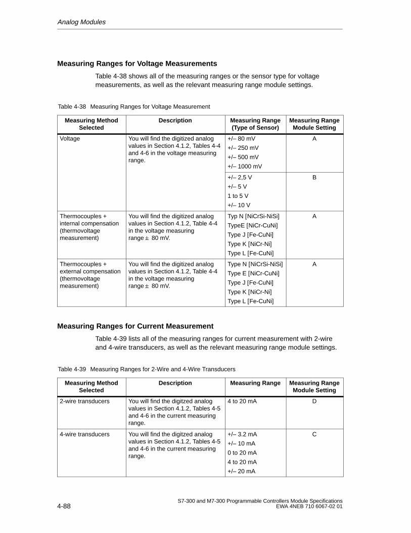
Analog Modules
4-88S7-300 and M7-300 Programmable Controllers Module Specifications
EWA 4NEB 710 6067-02 01
Measuring Ranges for Voltage Measurements
Table 4-38 shows all of the measuring ranges or the sensor type for voltagemeasurements, as well as the relevant measuring range module settings.
Table 4-38 Measuring Ranges for Voltage Measurement
Measuring MethodSelected
Description Measuring Range(Type of Sensor)
Measuring RangeModule Setting
Voltage You will find the digitized analogvalues in Section 4.1.2, Tables 4-4and 4-6 in the voltage measuringrange.
+/– 80 mV
+/– 250 mV
+/– 500 mV
+/– 1000 mV
A
+/– 2,5 V
+/– 5 V
1 to 5 V
+/– 10 V
B
Thermocouples +internal compensation(thermovoltagemeasurement)
You will find the digitized analogvalues in Section 4.1.2, Table 4-4in the voltage measuringrange 80 mV.
Typ N [NiCrSi-NiSi]TypeE [NiCr-CuNi]Type J [Fe-CuNi]Type K [NiCr-Ni]Type L [Fe-CuNi]
A
Thermocouples +external compensation(thermovoltagemeasurement)
You will find the digitized analogvalues in Section 4.1.2, Table 4-4in the voltage measuringrange 80 mV.
Type N [NiCrSi-NiSi]Type E [NiCr-CuNi]Type J [Fe-CuNi]Type K [NiCr-Ni]Type L [Fe-CuNi]
A
Measuring Ranges for Current Measurement
Table 4-39 lists all of the measuring ranges for current measurement with 2-wireand 4-wire transducers, as well as the relevant measuring range module settings.
Table 4-39 Measuring Ranges for 2-Wire and 4-Wire Transducers
Measuring MethodSelected
Description Measuring Range Measuring RangeModule Setting
2-wire transducers You will find the digitzed analogvalues in Section 4.1.2, Tables 4-5and 4-6 in the current measuringrange.
4 to 20 mA D
4-wire transducers You will find the digitzed analogvalues in Section 4.1.2, Tables 4-5and 4-6 in the current measuringrange.
+/– 3.2 mA
+/– 10 mA
0 to 20 mA
4 to 20 mA
+/– 20 mA
C
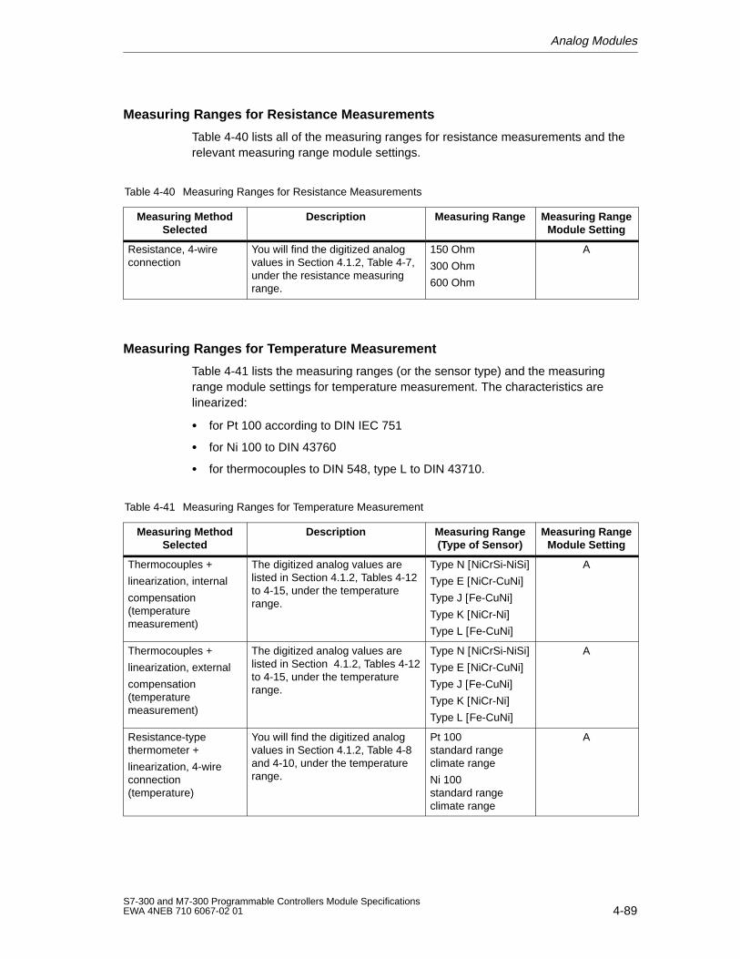
Analog Modules
4-89S7-300 and M7-300 Programmable Controllers Module SpecificationsEWA 4NEB 710 6067-02 01
Measuring Ranges for Resistance Measurements
Table 4-40 lists all of the measuring ranges for resistance measurements and therelevant measuring range module settings.
Table 4-40 Measuring Ranges for Resistance Measurements
Measuring MethodSelected
Description Measuring Range Measuring RangeModule Setting
Resistance, 4-wireconnection
You will find the digitized analogvalues in Section 4.1.2, Table 4-7,under the resistance measuringrange.
150 Ohm
300 Ohm
600 Ohm
A
Measuring Ranges for Temperature Measurement
Table 4-41 lists the measuring ranges (or the sensor type) and the measuringrange module settings for temperature measurement. The characteristics arelinearized:
for Pt 100 according to DIN IEC 751
for Ni 100 to DIN 43760
for thermocouples to DIN 548, type L to DIN 43710.
Table 4-41 Measuring Ranges for Temperature Measurement
Measuring MethodSelected
Description Measuring Range(Type of Sensor)
Measuring RangeModule Setting
Thermocouples +
linearization, internal
compensation(temperaturemeasurement)
The digitized analog values arelisted in Section 4.1.2, Tables 4-12to 4-15, under the temperaturerange.
Type N [NiCrSi-NiSi]Type E [NiCr-CuNi]Type J [Fe-CuNi]Type K [NiCr-Ni]Type L [Fe-CuNi]
A
Thermocouples +
linearization, external
compensation(temperaturemeasurement)
The digitized analog values arelisted in Section 4.1.2, Tables 4-12to 4-15, under the temperaturerange.
Type N [NiCrSi-NiSi]Type E [NiCr-CuNi]Type J [Fe-CuNi]Type K [NiCr-Ni]Type L [Fe-CuNi]
A
Resistance-typethermometer +
linearization, 4-wireconnection(temperature)
You will find the digitized analogvalues in Section 4.1.2, Table 4-8and 4-10, under the temperaturerange.
Pt 100standard rangeclimate range
Ni 100standard rangeclimate range
A
Analog Modules
4-90S7-300 and M7-300 Programmable Controllers Module Specifications
EWA 4NEB 710 6067-02 01
4.7 Analog Output Module SM 332; AO 4 12 Bit
In this Section
In this section, you will find:
The characteristic features of the analog output module SM 332; AO 4 12 Bit
The technical specifications of the analog output module SM 332;AO 4 12 Bit
You will learn:
How to start up the analog output module SM 332; AO 4 12 Bit
Which output ranges you can use with the analog output module SM 332;AO 4 12 Bit
The parameters with which you can influence the characteristic features of theanalog output module SM 332; AO 4 12 Bit
4.7.1 Characteristic Features and Technical Specifications of theAnalog Output Module SM 332; AO 4 12 Bit
Order No.
6ES7 332-5HD01-0AB0
Characteristic Features
The analog output module SM 332; AO 4 12 Bit has the following characteristicfeatures:
4 outputs in 4 channel groups
The individual output channels can be programmed as
– voltage outputs
– current outputs
Resolution 12 bits
Programmable diagnostics
Programmable diagnostics interrupt
Porgrammable substitute value output
Galvanic isolation to CPU and load voltage
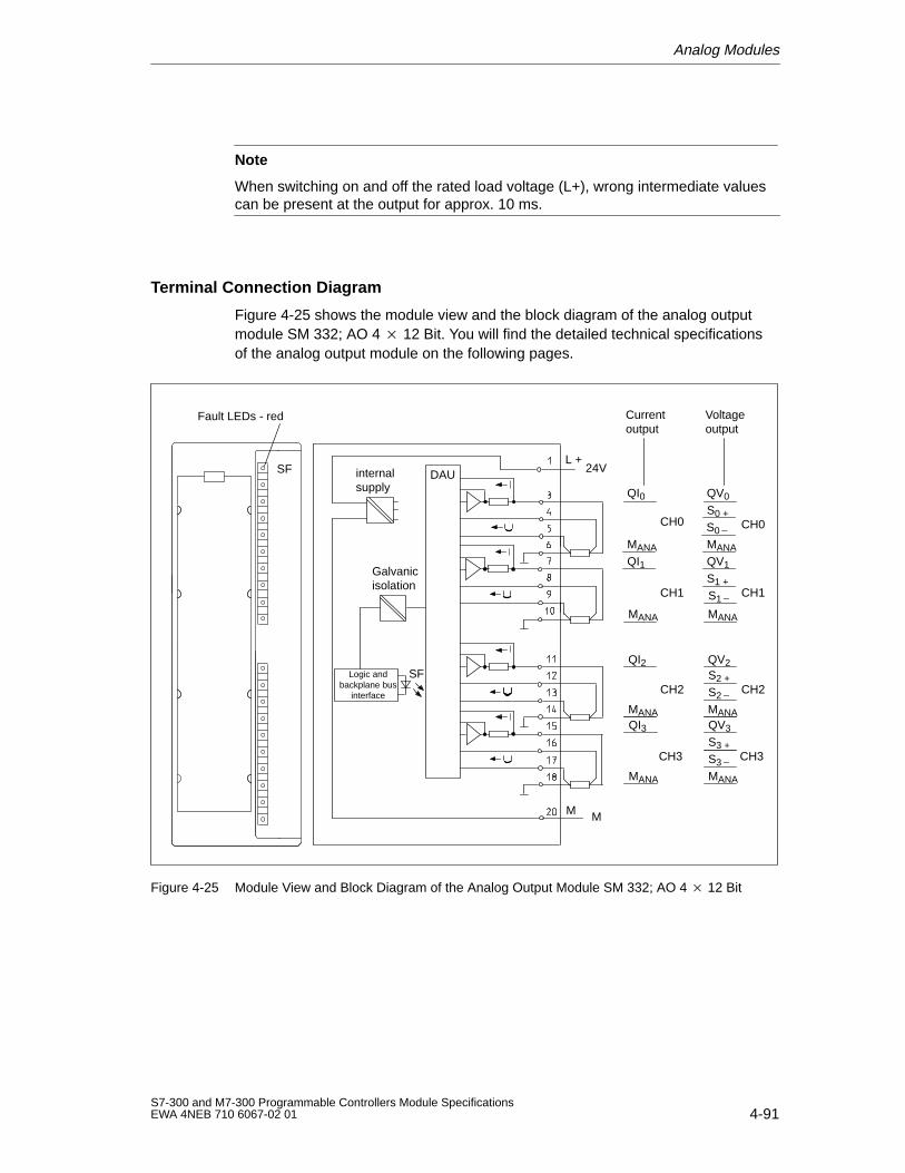
Analog Modules
4-91S7-300 and M7-300 Programmable Controllers Module SpecificationsEWA 4NEB 710 6067-02 01
Note
When switching on and off the rated load voltage (L+), wrong intermediate valuescan be present at the output for approx. 10 ms.
Terminal Connection Diagram
Figure 4-25 shows the module view and the block diagram of the analog outputmodule SM 332; AO 4 12 Bit. You will find the detailed technical specificationsof the analog output module on the following pages.
Currentoutput
QI0
MANA
QI1
MANA
QI2
MANAQI3
MANA
CH0
CH1
CH2
CH3
Voltageoutput
QV0
S0
S0 +
MANA
QV1
S1 +
S1
MANA
QV2S2 +
S2
MANAQV3
S3 +
S3
MANA
CH0
CH1
CH2
CH3
SF
Fault LEDs - red
internal supply
Galvanicisolation
Logic andbackplane bus
interface
SF
L +24VDAU
MM
Figure 4-25 Module View and Block Diagram of the Analog Output Module SM 332; AO 4 12 Bit
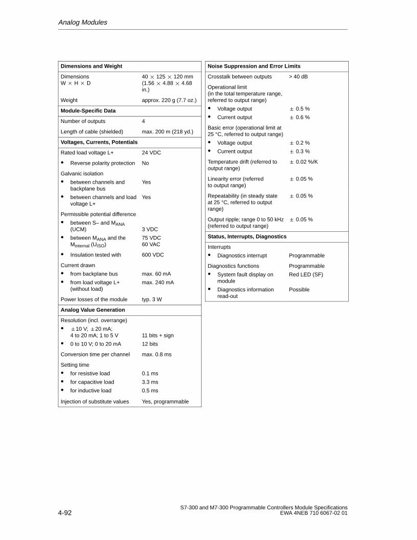
Analog Modules
4-92S7-300 and M7-300 Programmable Controllers Module Specifications
EWA 4NEB 710 6067-02 01
Dimensions and W eight
Dimensions W H D
40 125 120 mm(1.56 4.88 4.68in.)
Weight approx. 220 g (7.7 oz.)
Module-Specific Data
Number of outputs 4
Length of cable (shielded) max. 200 m (218 yd.)
Voltages, Currents, Potentials
Rated load voltage L+ 24 VDC
Reverse polarity protection No
Galvanic isolation
between channels andbackplane bus
between channels and loadvoltage L+
Yes
Yes
Permissible potential difference
between S– and MANA(UCM)
between MANA and theMinternal (UISO)
3 VDC
75 VDC60 VAC
Insulation tested with 600 VDC
Current drawn
from backplane bus
from load voltage L+(without load)
max. 60 mA
max. 240 mA
Power losses of the module typ. 3 W
Analog V alue Generation
Resolution (incl. overrange)
10 V; 20 mA;4 to 20 mA; 1 to 5 V
0 to 10 V; 0 to 20 mA
11 bits + sign
12 bits
Conversion time per channel max. 0.8 ms
Setting time
for resistive load
for capacitive load
for inductive load
0.1 ms
3.3 ms
0.5 ms
Injection of substitute values Yes, programmable
Noise Suppression and Error Limits
Crosstalk between outputs > 40 dB
Operational limit(in the total temperature range,referred to output range)
Voltage output
Current output
0.5 %
0.6 %
Basic error (operational limit at25 °C, referred to output range)
Voltage output
Current output
0.2 %
0.3 %
Temperature drift (referred tooutput range)
0.02 %/K
Linearity error (referredto output range)
0.05 %
Repeatability (in steady stateat 25 °C, referred to outputrange)
0.05 %
Output ripple; range 0 to 50 kHz(referred to output range)
0.05 %
Status, Interrupts, Diagnostics
Interrupts
Diagnostics interrupt Programmable
Diagnostics functions
System fault display onmodule
Diagnostics informationread-out
Programmable
Red LED (SF)
Possible
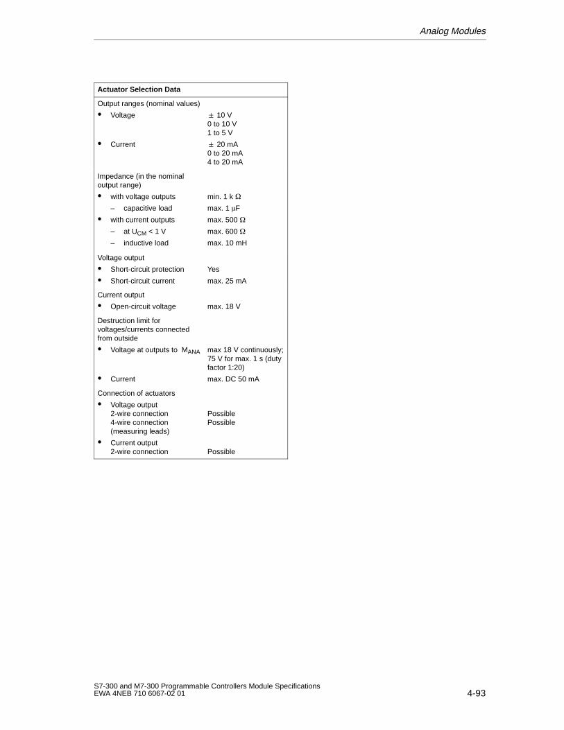
Analog Modules
4-93S7-300 and M7-300 Programmable Controllers Module SpecificationsEWA 4NEB 710 6067-02 01
Actuator Selection Data
Output ranges (nominal values)
Voltage
Current
10 V0 to 10 V1 to 5 V
20 mA0 to 20 mA4 to 20 mA
Impedance (in the nominaloutput range)
with voltage outputs
– capacitive load
with current outputs
– at UCM < 1 V
– inductive load
min. 1 k
max. 1 F
max. 500
max. 600
max. 10 mH
Voltage output
Short-circuit protection
Short-circuit current
Yes
max. 25 mA
Current output
Open-circuit voltage max. 18 V
Destruction limit forvoltages/currents connectedfrom outside
Voltage at outputs to MANA
Current
max 18 V continuously;75 V for max. 1 s (dutyfactor 1:20)
max. DC 50 mA
Connection of actuators
Voltage output2-wire connection4-wire connection(measuring leads)
Current output2-wire connection
PossiblePossible
Possible
Analog Modules
4-94S7-300 and M7-300 Programmable Controllers Module Specifications
EWA 4NEB 710 6067-02 01
4.7.2 Starting Up the Analog Output Module SM 332; AO 4 12 Bit
Parameter Assignment
The functions of the analog output module SM 332; AO 4 12 Bit are set asfollows:
with STEP 7 (also see STEP 7 User Manual) or
in the user program by means of SFCs (see STEP7 System and StandardFunctions Reference Manual).
Note
If you modify output ranges when the analog output module SM 332;AO 4 12 Bit is in operation, intermediate values may appear at the output!
Default Settings
The analog output module has default settings for the type of output, diagnostics,interrupts, etc. (see Table 4-20).
These default settings are valid, if you have not re-initialized the module withSTEP 7 .
Parameter Assignment
You can configure each output channel of the SM 332; AO 4 12 Bit individually.
Advantage: You can assign individual parameters for each output channel.
When you set the parameters with SFCs in the user program, the parameters areassigned to channel groups. Each output channel of the analog output moduleSM 332; AO 4 12 Bit is then assigned to one channel group, i.e. output channel0 = channel group 0 (see Fig. A-4 in Appendix A).
Unused Output Channels
To make sure that unused output channels of the analog output module SM 332;AO 4 12 Bit are dead, you must deactivate them and leave them open.Deactivate an output channel using the “Output” parameter block whenprogramming with STEP 7 (see Section 4.3.4).
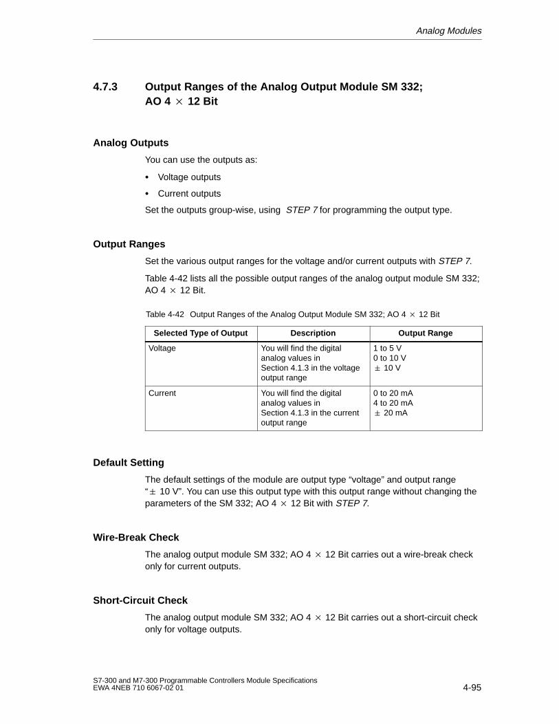
Analog Modules
4-95S7-300 and M7-300 Programmable Controllers Module SpecificationsEWA 4NEB 710 6067-02 01
4.7.3 Output Ranges of the Analog Output Module SM 332;AO 4 12 Bit
Analog Outputs
You can use the outputs as:
Voltage outputs
Current outputs
Set the outputs group-wise, using STEP 7 for programming the output type.
Output Ranges
Set the various output ranges for the voltage and/or current outputs with STEP 7.
Table 4-42 lists all the possible output ranges of the analog output module SM 332;AO 4 12 Bit.
Table 4-42 Output Ranges of the Analog Output Module SM 332; AO 4 12 Bit
Selected T ype of Output Description Output Range
Voltage You will find the digitalanalog values inSection 4.1.3 in the voltageoutput range
1 to 5 V0 to 10 V 10 V
Current You will find the digitalanalog values inSection 4.1.3 in the currentoutput range
0 to 20 mA4 to 20 mA 20 mA
Default Setting
The default settings of the module are output type “voltage” and output range“ 10 V”. You can use this output type with this output range without changing theparameters of the SM 332; AO 4 12 Bit with STEP 7.
Wire-Break Check
The analog output module SM 332; AO 4 12 Bit carries out a wire-break checkonly for current outputs.
Short-Circuit Check
The analog output module SM 332; AO 4 12 Bit carries out a short-circuit checkonly for voltage outputs.
Analog Modules
4-96S7-300 and M7-300 Programmable Controllers Module Specifications
EWA 4NEB 710 6067-02 01
Substitute Values
You can configure the SM 332; AO 4 12 Bit for the CPU operating mode STOPas follows: Output Substitute Values (default: 0 mA/0 V) or Hold Last Value.
For the output ranges 4 to 20 mA and 1 to 5 V you must set the substitute valueE500H in order for the output to remain de-energized (see Tables 4-17 and 4-18).
4.8 Analog Output Module SM 332; AO 2 12 Bit
In this Section
In this section, you will find:
The characteristic features of the analog output module SM 332; AO 2 12 Bit
The technical specifications of the analog output module SM 332;AO 2 12 Bit
You will learn:
How to start up the analog output module SM 332; AO 2 12 Bit
Which output ranges you can use with the analog output module SM 332;AO 2 12 Bit
The parameters with which you can influence the characteristic features of theanalog output module SM 332; AO 2 12 Bit
Analog Modules
4-97S7-300 and M7-300 Programmable Controllers Module SpecificationsEWA 4NEB 710 6067-02 01
4.8.1 Characteristic Features and Technical Specifications of theAnalog Output Module SM 332; AO 2 12 Bit
Order No.
6ES7 332-5HB01-0AB0
Characteristic Features
The analog output module SM 332; AO 2 12 Bit has the following characteristicfeatures:
2 output in 2 channels groups
The individual output channels can be programmed as
– voltage outputs
– current outputs
Resolution 12 bits
Programmable diagnostics
Programmable diagnostics interrupt
Programmable substitute value output
Galvanic isolation to CPU and load voltage
Note
When switching on and off the rated load voltage (L+), wrong intermediate valuescan be present at the output for approx. 10 ms.
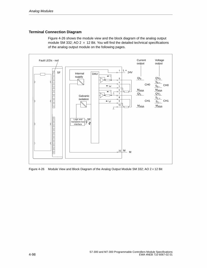
Analog Modules
4-98S7-300 and M7-300 Programmable Controllers Module Specifications
EWA 4NEB 710 6067-02 01
Terminal Connection Diagram
Figure 4-26 shows the module view and the block diagram of the analog outputmodule SM 332; AO 2 12 Bit. You will find the detailed technical specificationsof the analog output module on the following pages.
Currentoutput
QI0
MANA
QI1
MANA
CH0
CH1
Voltageoutput
QV0
S0
S0 +
MANA
QV1
S1 +
S1
MANA
CH0
CH1
SF
Fault LEDs - red
Internal supply
Galvanicisolation
Logic andbackplane bus
interface
SF
L +24VDAU
MM
Figure 4-26 Module View and Block Diagram of the Analog Output Module SM 332; AO 212 Bit
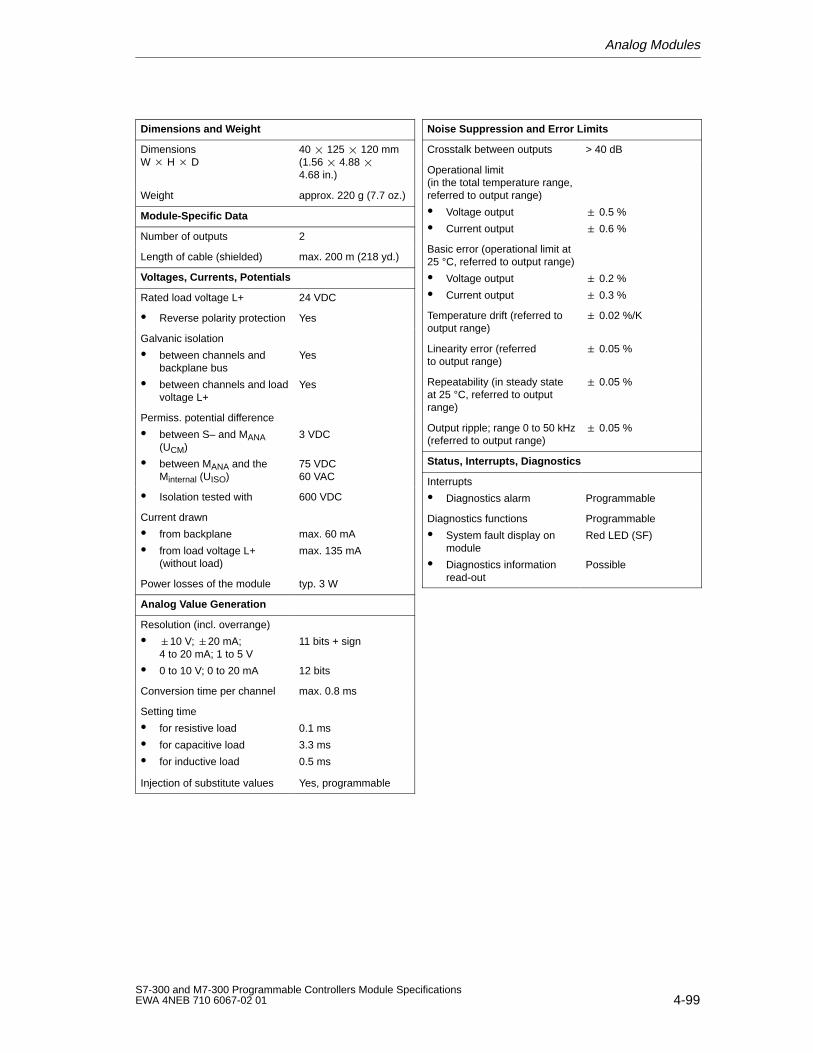
Analog Modules
4-99S7-300 and M7-300 Programmable Controllers Module SpecificationsEWA 4NEB 710 6067-02 01
Dimensions and W eight
Dimensions W H D
40 125 120 mm(1.56 4.88 4.68 in.)
Weight approx. 220 g (7.7 oz.)
Module-Specific Data
Number of outputs 2
Length of cable (shielded) max. 200 m (218 yd.)
Voltages, Currents, Potentials
Rated load voltage L+ 24 VDC
Reverse polarity protection Yes
Galvanic isolation
between channels andbackplane bus
between channels and loadvoltage L+
Yes
Yes
Permiss. potential difference
between S– and MANA(UCM)
between MANA and theMinternal (UISO)
3 VDC
75 VDC60 VAC
Isolation tested with 600 VDC
Current drawn
from backplane
from load voltage L+(without load)
max. 60 mA
max. 135 mA
Power losses of the module typ. 3 W
Analog V alue Generation
Resolution (incl. overrange)
10 V; 20 mA;4 to 20 mA; 1 to 5 V
0 to 10 V; 0 to 20 mA
11 bits + sign
12 bits
Conversion time per channel max. 0.8 ms
Setting time
for resistive load
for capacitive load
for inductive load
0.1 ms
3.3 ms
0.5 ms
Injection of substitute values Yes, programmable
Noise Suppression and Error Limits
Crosstalk between outputs > 40 dB
Operational limit(in the total temperature range,referred to output range)
Voltage output
Current output
0.5 %
0.6 %
Basic error (operational limit at25 °C, referred to output range)
Voltage output
Current output
0.2 %
0.3 %
Temperature drift (referred tooutput range)
0.02 %/K
Linearity error (referredto output range)
0.05 %
Repeatability (in steady stateat 25 °C, referred to outputrange)
0.05 %
Output ripple; range 0 to 50 kHz(referred to output range)
0.05 %
Status, Interrupts, Diagnostics
Interrupts
Diagnostics alarm Programmable
Diagnostics functions
System fault display onmodule
Diagnostics informationread-out
Programmable
Red LED (SF)
Possible
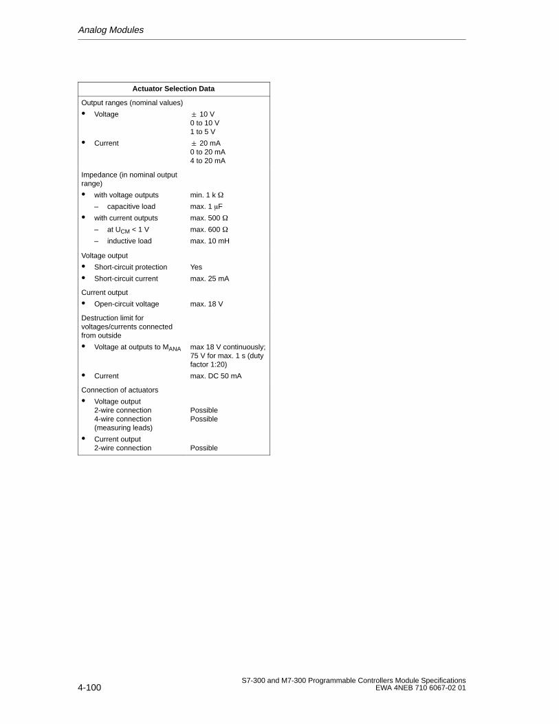
Analog Modules
4-100S7-300 and M7-300 Programmable Controllers Module Specifications
EWA 4NEB 710 6067-02 01
Actuator Selection Data
Output ranges (nominal values)
Voltage
Current
10 V0 to 10 V1 to 5 V
20 mA0 to 20 mA4 to 20 mA
Impedance (in nominal outputrange)
with voltage outputs
– capacitive load
with current outputs
– at UCM < 1 V
– inductive load
min. 1 k
max. 1 F
max. 500
max. 600
max. 10 mH
Voltage output
Short-circuit protection
Short-circuit current
Yes
max. 25 mA
Current output
Open-circuit voltage max. 18 V
Destruction limit forvoltages/currents connectedfrom outside
Voltage at outputs to MANA
Current
max 18 V continuously;75 V for max. 1 s (dutyfactor 1:20)
max. DC 50 mA
Connection of actuators
Voltage output2-wire connection4-wire connection(measuring leads)
Current output2-wire connection
PossiblePossible
Possible
Analog Modules
4-101S7-300 and M7-300 Programmable Controllers Module SpecificationsEWA 4NEB 710 6067-02 01
4.8.2 Starting Up the Analog Output Module SM 332; AO 2 12 Bit
Parameter Assignment
The functions of the analog output module SM 332; AO 2 12 Bit are set asfollows:
with STEP 7 (see aso STEP 7 User Manual) or
in the user program by means of SFCs (see STEP 7 System and StandardFunctions Reference Manual).
Note
If you modify output ranges when the analog output module SM 332; AO 2 12Bit is in operation, intermediate values may appear at the output!
Default Settings
The analog output module has default settings for the type of output, diagnostics,interrupts, etc. (see Table 4-20).
These default settings are valid, if you have not re-initialized the module withSTEP 7
Parameter Assignment
You can configure each output channel of the SM 332; AO 2 12 Bit individually.
Advantage: You can assign individual parameters for each output channel.
When you configure with SFCs in the user program, the parameters are assignedto channel groups. Each output channel of the analog output module SM 332;AO 2 12 Bit is then assigned to one channel group, i.e. output channel 0 =channel group 0 (see Fig. A-3 in Appendix A).
Unused Output Channels
To make sure that unused output channels of the analog output module SM 332;AO 2 12 Bit are dead, you must deactivate them and leave them open.Deactivate an output channel using the “Output” parameter block of STEP 7 (seeSection 4.3.4).
Analog Modules
4-102S7-300 and M7-300 Programmable Controllers Module Specifications
EWA 4NEB 710 6067-02 01
4.8.3 Output Ranges of the Analog Output Module SM 332;AO 212 Bit
Analog Outputs
You can use the outputs as:
Voltage outputs
Current outputs
You make the output settings channel-group-wise, using STEP 7.
Output Ranges
Set the various output ranges for the voltage and/or current outputs with STEP 7.
Table 4-43 lists all the possible output ranges of the analog output module SM 332;AO 2 12 Bit.
Table 4-43 Output Ranges of the Analog Output Module SM 332; AO 2 12 Bit
Selected T ype of Output Description Output Range
Voltage You will find the digitalanalog values inSection 4.1.3 in the voltageoutput range
1 to 5 V0 to 10 V 10 V
Current You will find the digitalanalog values inSection 4.1.3 in the currentoutput range
0 to 20 mA4 to 20 mA 20 mA
Default Setting
The default settings of the module are output type “voltage” and output range“ 10 V”. You can use this output type with this output range without changing theparameters of the SM 332; AO 2 12 Bit with STEP 7.
Wire-Break Check
The analog output module SM 332; AO 2 12 Bit carries out a wire-break checkonly for current outputs.
Short-Circuit Check
The analog output module SM 332; AO 2 12 Bit carries out a short-circuit checkonly for voltage outputs.
Analog Modules
4-103S7-300 and M7-300 Programmable Controllers Module SpecificationsEWA 4NEB 710 6067-02 01
Substitute Values
You can parameterize the SM 332; AO 2 12 Bit for the CPU operating modeSTOP as follows: Output Substitute Values (default: 0 mA/0 V) or Hold Last Value.
For the output ranges 4 to 20 mA and 1 to 5 V you must set the substitute valueE500H in order for the output to remain de-energized (see Tables 4-17 and 4-18).
4.9 Analog Output Module SM 332; AO 4 16 Bit
Order No.
6ES7 332-7ND00-0AB0
Characteristic Features
The analog output module SM 332; AO 4 16 Bit has the following characteristicfeatures:
4 outputs in 4 channel groups
The individual output channels can be programmed as:
– Voltage outputs
– Current outputs
Resolution of 16 bits
Programmable diagnostics
Programmable diagnostics interrupt
Programmable substitute value output
Galvanic isolation to CPU and analog output channel
Galvanic isolation analog output channel-to-channel
Galvanic isolation analog output and L+, M
Galvanic isolation CPU and L+, M
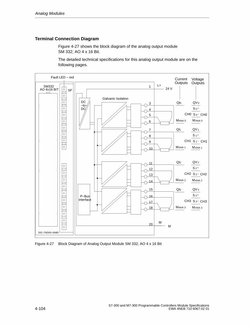
Analog Modules
4-104S7-300 and M7-300 Programmable Controllers Module Specifications
EWA 4NEB 710 6067-02 01
Terminal Connection Diagram
Figure 4-27 shows the block diagram of the analog output module SM 332; AO 4 x 16 Bit.
The detailed technical specifications for this analog output module are on thefollowing pages.
SF
QI0Galvanic Isolation
CH0 CH0
CurrentOutputs
VoltageOutputs
MANA 0
QV0
S 0 +
S 0 –
MANA 0
Fault LED – red
QI1
CH1 CH1
MANA 1
QV1
S 1 +
S 1 –
MANA 1
QI2
CH2 CH2
MANA 2
QV2
S 2 +
S 2 –
MANA 2
QI3
CH3 CH3
MANA 3
QV3
S 3 +
S 3 –
MANA 3
L+24 V
MM
332–7ND00–0AB0
DC
P–Businterface
–to–DC
1
3
4
5
6
7
8
9
10
11
12
13
14
15
16
17
18
20
SM332AO 4x16 BIT
Figure 4-27 Block Diagram of Analog Output Module SM 332; AO 4 x 16 Bit
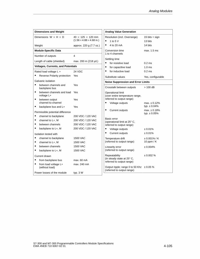
Analog Modules
4-105S7-300 and M7-300 Programmable Controllers Module SpecificationsEWA 4NEB 710 6067-02 01
Dimensions and W eight
Dimensions W H D 40 125 120 mm(1.564.884.68 in.)
Weight approx. 220 g (7.7 oz.)
Module-Specific Data
Number of outputs 4
Length of cable (shielded) max. 200 m (218 yd.)
Voltages, Currents, and Potentials
Rated load voltage L +
Reverse Polarity protection
24 VDC
Yes
Galvanic isolation
between channels and backplane bus
between channels and loadvoltage L+
between outputchannel-to-channel
backplane bus and L+
Yes
Yes
Yes
Yes
Permissible potential difference
channel to backplane
channel to L+, M
between channels
backplane to L+, M
200 VDC / 120 VAC
200 VDC / 120 VAC
200 VDC / 120 VAC
200 VDC / 120 VAC
Isolation tested with
channel to backplane
channel to L+, M
between channels
backplane to L+, M
1500 VAC
1500 VAC
1500 VAC
1500 VAC
Current drawn
from backplane bus
from load voltage L+(without load)
max. 60 mA
max. 240 mA
Power losses of the module typ. 3 W
Analog V alue Generation
Resolution (incl. Overrange)
1 to 5 V
4 to 20 mA
15 bits + sign
13 bits
14 bits
Conversion time 1 to 4 channels
max. 1.5 ms
Settling time
for resistive load
for capacitive load
for inductive load
0.2 ms
1.0 ms
0.2 ms
Substitute values Yes, configurable
Noise Suppression and Error Limits
Crosstalk between outputs > 100 dB
Operational limit (over entire temperature range,referred to output range)
Voltage outputs
Current outputs
max. ± 0.12% typ. ± 0.04%
max. ± 0.18%typ. ± 0.05%
Basic error (operational limit at 25° C,referred to output range)
Voltage outputs
Current outputs
± 0.01%
± 0.01%
Temperature drift (referred to output range)
± 0.001% / K 10 ppm / K
Linearity error (referred to output range)
± 0.004%
Repeatability (in steady state at 25° C,referred to output range)
± 0.002 %
Output ripple; range 0 to 50 Khz(referred to output range)
± 0.05 %
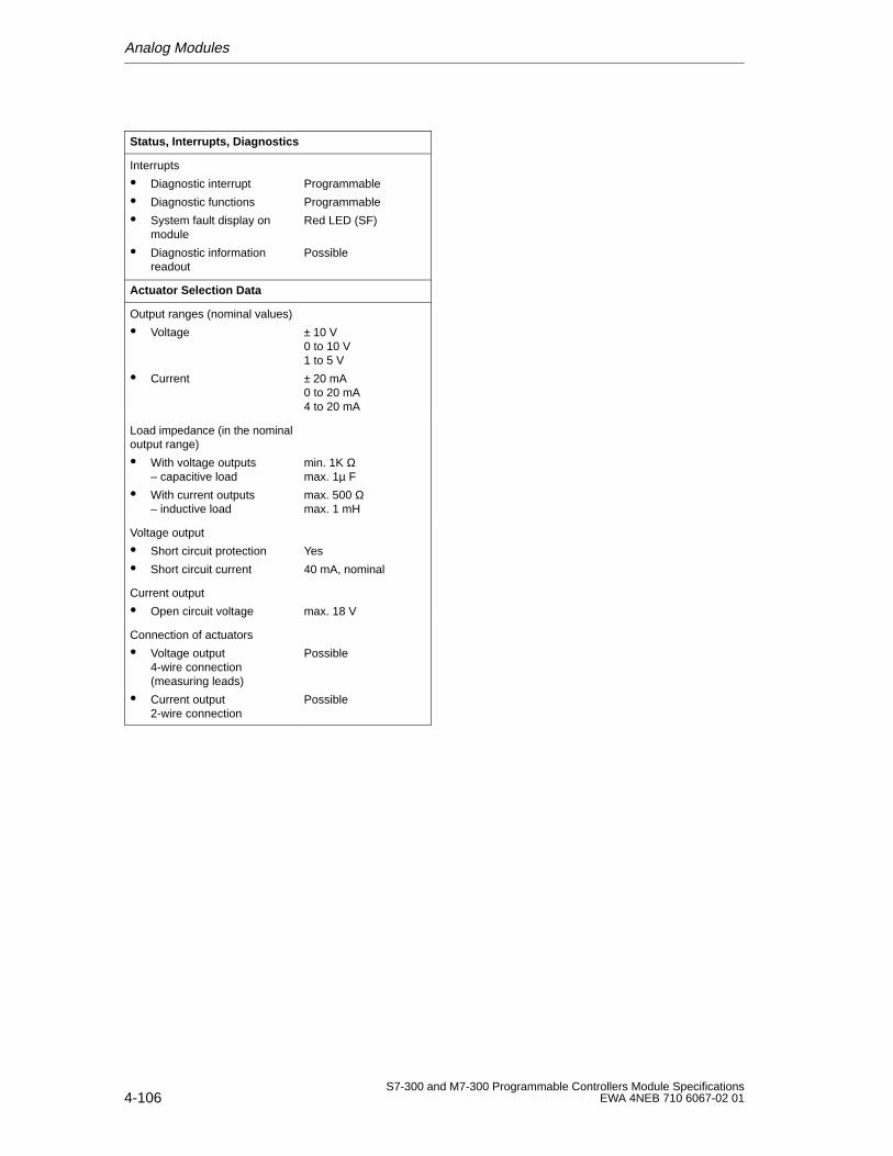
Analog Modules
4-106S7-300 and M7-300 Programmable Controllers Module Specifications
EWA 4NEB 710 6067-02 01
Status, Interrupts, Diagnostics
Interrupts
Diagnostic interrupt
Diagnostic functions
System fault display onmodule
Diagnostic informationreadout
Programmable
Programmable
Red LED (SF)
Possible
Actuator Selection Data
Output ranges (nominal values)
Voltage
Current
± 10 V0 to 10 V1 to 5 V
± 20 mA0 to 20 mA4 to 20 mA
Load impedance (in the nominaloutput range)
With voltage outputs – capacitive load
With current outputs– inductive load
min. 1K Ωmax. 1µ F
max. 500 Ωmax. 1 mH
Voltage output
Short circuit protection
Short circuit current
Yes
40 mA, nominal
Current output
Open circuit voltage max. 18 V
Connection of actuators
Voltage output 4-wire connection(measuring leads)
Current output2-wire connection
Possible
Possible
Analog Modules
4-107S7-300 and M7-300 Programmable Controllers Module SpecificationsEWA 4NEB 710 6067-02 01
4.9.1 Starting Up the Analog Output Module SM 332; AO 4 16 Bit
Parameter Assignment
The functions of the analog output module SM 332; AO 4 16 Bit are set:
with STEP 7 (see the STEP 7 User Manual) or
in the user program by means of SFCs (see the STEP 7 System and StandardFunctions Reference Manual)
Note
If you modify output ranges when the analog output module SM 332; AO 4 X 16 Bit is in operation, intermediate values may appear at the out-put.
You can configure each output channel of the SM 332; AO 4 x 16 Bit individually.
Advantage: you can assign individual parameters for each output channel.
When you set the parameters with SFCs in the user program, the parameters areassigned to channel groups. Each output channel of the analog output moduleSM 332; AO 4 x 16 Bit is then assigned to one channel group, i.e., output channel0 = channel group 0.
Default Setting
The default settings of the module are diagnostic interrupt disabled: groupdiagnostics disabled; output type: voltage; output range: ± 10 V; and reaction toCPU STOP: outputs without voltage or current. You can use this output type withthis output range without changing the parameters of the SM 332; AO 4 x 16 Bitwith STEP 7.
Unused Output Channels
Unused output channels of the analog output module SM 332; AO 4 x 16 Bitshould be deactivated by using the Output parameter block when programmingwith STEP 7 and field wiring terminals should be empty.
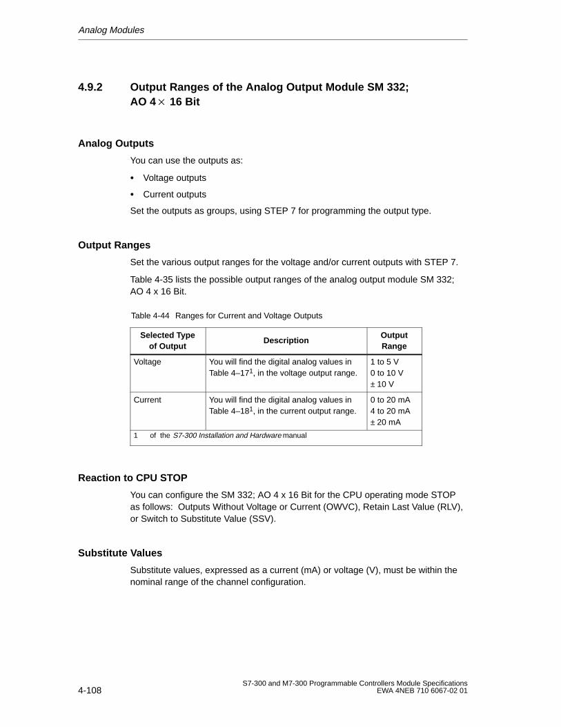
Analog Modules
4-108S7-300 and M7-300 Programmable Controllers Module Specifications
EWA 4NEB 710 6067-02 01
4.9.2 Output Ranges of the Analog Output Module SM 332; AO 4 16 Bit
Analog Outputs
You can use the outputs as:
Voltage outputs
Current outputs
Set the outputs as groups, using STEP 7 for programming the output type.
Output Ranges
Set the various output ranges for the voltage and/or current outputs with STEP 7.
Table 4-35 lists the possible output ranges of the analog output module SM 332;AO 4 x 16 Bit.
Table 4-44 Ranges for Current and Voltage Outputs
Selected T ypeof Output
DescriptionOutputRange
Voltage You will find the digital analog values inTable 4–171, in the voltage output range.
1 to 5 V0 to 10 V± 10 V
Current You will find the digital analog values inTable 4–181, in the current output range.
0 to 20 mA4 to 20 mA± 20 mA
1 of the S7-300 Installation and Hardware manual
Reaction to CPU STOP
You can configure the SM 332; AO 4 x 16 Bit for the CPU operating mode STOPas follows: Outputs Without Voltage or Current (OWVC), Retain Last Value (RLV),or Switch to Substitute Value (SSV).
Substitute Values
Substitute values, expressed as a current (mA) or voltage (V), must be within thenominal range of the channel configuration.
Analog Modules
4-109S7-300 and M7-300 Programmable Controllers Module SpecificationsEWA 4NEB 710 6067-02 01
4.10 Analog Input/Output Module SM 334; AI 4/AO 2 8/8 Bit
In this Section
In this section you will get to know:
The characteristic features of the analog input/output module SM 334; AI 4/AO 2 8/8 Bit
The technical specifications of the analog input/output moduleSM 334; AI 4/AO 2 8/8 Bit
You will learn:
How to start up the analog input/output moduleSM 334; AI 4/AO 2 8/8 Bit
Which measuring and output ranges the analog input/output moduleSM 334; AI 4/AO 2 8/8 Bit has
4.10.1 Characteristic Features and Technical Specifications of theAnalog Input/Output Module SM 334; AI 4/AO 2 8/8 Bit
Order No.
6ES7 334-0CE01-0AA0
Characteristic Features
The analog input/output module SM 334: AI 4/AO 2 8/8 Bit has the followingcharacteristic features:
Four input and two output channels
Resolution 8 bits
Measuring range of 0 to 10 V or 0 to 20 mA
Output range of 0 to 10 V or 0 to 20 mA
Both voltage and current output options
Non-isolated to CPU
Galvanic isolation to load voltage
Special Feature: Measuring Range and Output Range Selection
You cannot assign parameters to the SM 334 analog input/output module with four8-bit analog input channels and two 8-bit analog output channels. Select themeasuring range of the input channels and the output range of the output channelsvia the wiring (see Figure 4-28).
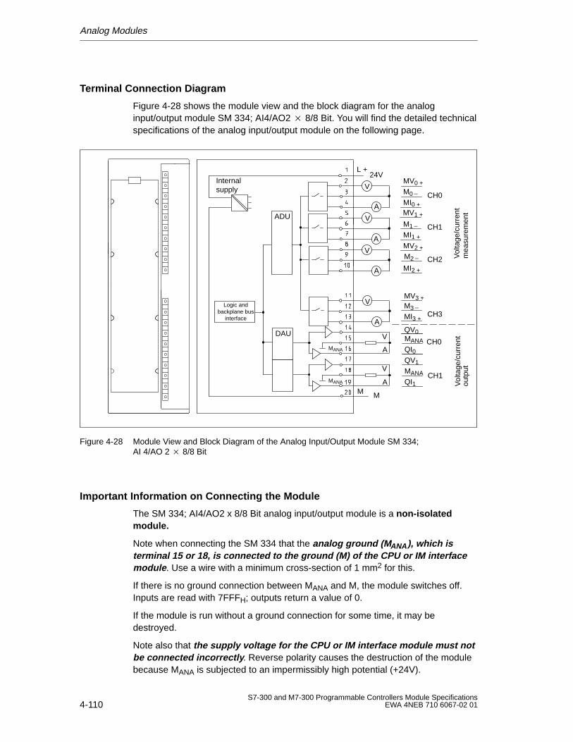
Analog Modules
4-110S7-300 and M7-300 Programmable Controllers Module Specifications
EWA 4NEB 710 6067-02 01
Terminal Connection Diagram
Figure 4-28 shows the module view and the block diagram for the analoginput/output module SM 334; AI4/AO2 8/8 Bit. You will find the detailed technicalspecifications of the analog input/output module on the following page.
Internal supply
Logic andbackplane bus
interface
L +24V
DAU
MM
MV0 +
M0
MV1 +
MI0 +
M1
MI1 +
MV2 +
M2
MI2 +
MV3 +M3
MI3 +
CH0
CH1
CH2
CH3
QV0MANA
QI0QV1
MANA
QI1
CH0
CH1
ADU
Vol
tage
/cur
rent
outp
utV
olta
ge/c
urre
ntm
easu
rem
ent
MANA
MANA
V
A
V
A
A
V
A
V
A
V
V
A
Figure 4-28 Module View and Block Diagram of the Analog Input/Output Module SM 334; AI 4/AO 2 8/8 Bit
Important Information on Connecting the Module
The SM 334; AI4/AO2 x 8/8 Bit analog input/output module is a non-isolatedmodule.
Note when connecting the SM 334 that the analog ground (M ANA ), which isterminal 15 or 18, is connected to the ground (M) of the CPU or IM interfacemodule . Use a wire with a minimum cross-section of 1 mm2 for this.
If there is no ground connection between MANA and M, the module switches off.Inputs are read with 7FFFH; outputs return a value of 0.
If the module is run without a ground connection for some time, it may bedestroyed.
Note also that the supply voltage for the CPU or IM interface module must notbe connected incorrectly . Reverse polarity causes the destruction of the modulebecause MANA is subjected to an impermissibly high potential (+24V).
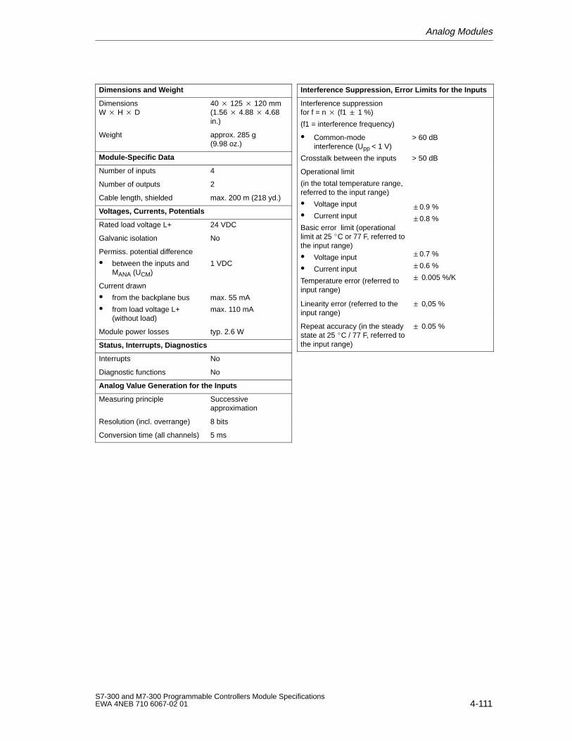
Analog Modules
4-111S7-300 and M7-300 Programmable Controllers Module SpecificationsEWA 4NEB 710 6067-02 01
Dimensions and W eight
Dimensions W H D
40 125 120 mm(1.56 4.88 4.68in.)
Weight approx. 285 g(9.98 oz.)
Module-Specific Data
Number of inputs 4
Number of outputs 2
Cable length, shielded max. 200 m (218 yd.)
Voltages, Currents, Potentials
Rated load voltage L+ 24 VDC
Galvanic isolation No
Permiss. potential difference
between the inputs andMANA (UCM)
1 VDC
Current drawn
from the backplane bus
from load voltage L+(without load)
max. 55 mA
max. 110 mA
Module power losses typ. 2.6 W
Status, Interrupts, Diagnostics
Interrupts No
Diagnostic functions No
Analog V alue Generation for the Inputs
Measuring principle Successiveapproximation
Resolution (incl. overrange) 8 bits
Conversion time (all channels) 5 ms
Interference Suppression, Error Limits for the Inputs
Interference suppressionfor f = n (f1 1 %)
(f1 = interference frequency)
Common-modeinterference (Upp < 1 V)
Crosstalk between the inputs
> 60 dB
> 50 dB
Operational limit
(in the total temperature range,referred to the input range)
Voltage input
Current input
Basic error limit (operationallimit at 25 C or 77 F, referred tothe input range)
Voltage input
Current input
Temperature error (referred toinput range)
0.9 %
0.8 %
0.7 %
0.6 %
0.005 %/K
Linearity error (referred to theinput range)
0,05 %
Repeat accuracy (in the steadystate at 25 C / 77 F, referred tothe input range)
0.05 %
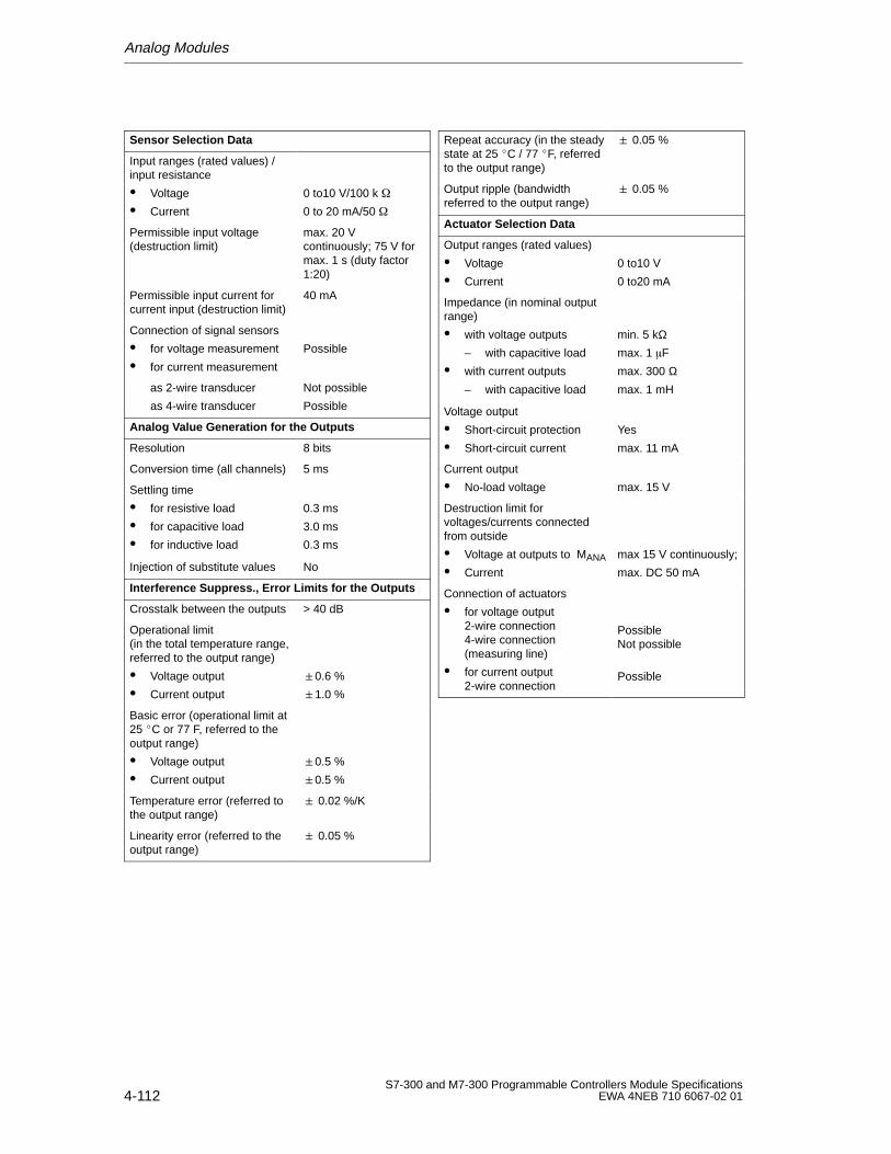
Analog Modules
4-112S7-300 and M7-300 Programmable Controllers Module Specifications
EWA 4NEB 710 6067-02 01
Sensor Selection Data
Input ranges (rated values) /input resistance
Voltage
Current
0 to10 V/100 k
0 to 20 mA/50
Permissible input voltage (destruction limit)
max. 20 Vcontinuously; 75 V formax. 1 s (duty factor1:20)
Permissible input current forcurrent input (destruction limit)
40 mA
Connection of signal sensors
for voltage measurement
for current measurement
Possible
as 2-wire transducer
as 4-wire transducer
Not possible
Possible
Analog V alue Generation for the Outputs
Resolution 8 bits
Conversion time (all channels) 5 ms
Settling time
for resistive load
for capacitive load
for inductive load
0.3 ms
3.0 ms
0.3 ms
Injection of substitute values No
Interference Suppress., Error Limits for the Outputs
Crosstalk between the outputs > 40 dB
Operational limit(in the total temperature range,referred to the output range)
Voltage output
Current output
0.6 %
1.0 %
Basic error (operational limit at25 C or 77 F, referred to theoutput range)
Voltage output
Current output
0.5 %
0.5 %
Temperature error (referred tothe output range)
0.02 %/K
Linearity error (referred to theoutput range)
0.05 %
Repeat accuracy (in the steadystate at 25 C / 77 F, referredto the output range)
0.05 %
Output ripple (bandwidthreferred to the output range)
0.05 %
Actuator Selection Data
Output ranges (rated values)
Voltage
Current
0 to10 V
0 to20 mA
Impedance (in nominal outputrange)
with voltage outputs
– with capacitive load
with current outputs
– with capacitive load
min. 5 kΩmax. 1 F
max. 300 Ωmax. 1 mH
Voltage output
Short-circuit protection
Short-circuit current
Yes
max. 11 mA
Current output
No-load voltage max. 15 V
Destruction limit forvoltages/currents connectedfrom outside
Voltage at outputs to MANA
Current
max 15 V continuously;
max. DC 50 mA
Connection of actuators
for voltage output2-wire connection4-wire connection(measuring line)
for current output2-wire connection
PossibleNot possible
Possible
Analog Modules
4-113S7-300 and M7-300 Programmable Controllers Module SpecificationsEWA 4NEB 710 6067-02 01
4.10.2 Starting Up the Analog Input/Output Module SM 334;AI 4/AO 2 8/8 Bit
Electrical Design
You must connect one of the chassis ground terminals (MANA) of the analoginput/output module SM 334; AI 4/AO 2 8/8 Bit to the chassis ground terminal ofthe CPU (see Figure 4-28). Use a cable with a cross-section conductor of at least1 mm2 for this purpose.
Unused Channels
You must short-circuit unused input channels and you should connect them toMANA. You thus obtain optimum interference protection for your analog module.
Unused output channels must be left open.
4.10.3 Measurement Method and Type of Output of the AnalogInput/Output Module SM 334; AI 4/AO 2 8/8 Bit
Selecting the Measurement Method and the Type of Output
Select the measuring method of an input channel (voltage, current) by wiring theinput channel appropriately.
Select the type of output of an output channel (voltage, current) by wiring theoutput channel appropriately.
The analog input/output module SM 332; AI 4/AO 2 8/8 Bit cannot beprogrammed.
Addressing
The module’s inputs and outputs are addressed starting at the module startaddress.
The address of a channel is obtained from the module start address and anaddress offset.
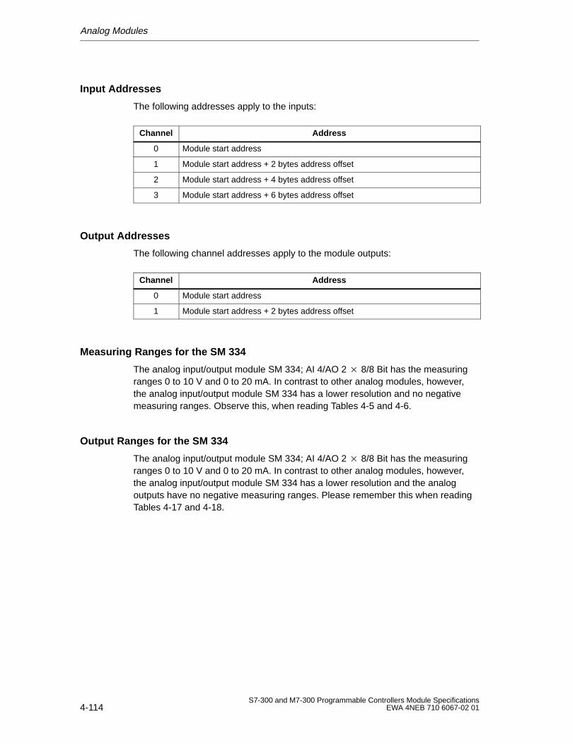
Analog Modules
4-114S7-300 and M7-300 Programmable Controllers Module Specifications
EWA 4NEB 710 6067-02 01
Input Addresses
The following addresses apply to the inputs:
Channel Address
0 Module start address
1 Module start address + 2 bytes address offset
2 Module start address + 4 bytes address offset
3 Module start address + 6 bytes address offset
Output Addresses
The following channel addresses apply to the module outputs:
Channel Address
0 Module start address
1 Module start address + 2 bytes address offset
Measuring Ranges for the SM 334
The analog input/output module SM 334; AI 4/AO 2 8/8 Bit has the measuringranges 0 to 10 V and 0 to 20 mA. In contrast to other analog modules, however,the analog input/output module SM 334 has a lower resolution and no negativemeasuring ranges. Observe this, when reading Tables 4-5 and 4-6.
Output Ranges for the SM 334
The analog input/output module SM 334; AI 4/AO 2 8/8 Bit has the measuringranges 0 to 10 V and 0 to 20 mA. In contrast to other analog modules, however,the analog input/output module SM 334 has a lower resolution and the analogoutputs have no negative measuring ranges. Please remember this when readingTables 4-17 and 4-18.
Analog Modules
4-115S7-300 and M7-300 Programmable Controllers Module SpecificationsEWA 4NEB 710 6067-02 01
4.11 Analog Input/Output Module SM 334; AI 4/AO 212 Bit
Order No.
6ES7 334–0KE00–0AB0
Characteristic Features
The SM 334 has the following characteristic features:
4 inputs in two groups
2 outputs (voltage outputs)
Measured value resolution of 12 bits + sign
Type of measurement selectable
– Voltage
– Resistance
– Temperature
Isolated from CPU
Isolated from load voltage
Note
Below the rated load voltage range, incorrect intermediate values occur at theoutput when the rated load voltage supply is switched on/off.
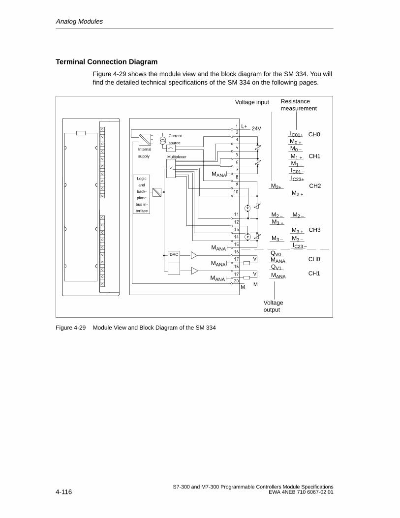
Analog Modules
4-116S7-300 and M7-300 Programmable Controllers Module Specifications
EWA 4NEB 710 6067-02 01
Terminal Connection Diagram
Figure 4-29 shows the module view and the block diagram for the SM 334. You willfind the detailed technical specifications of the SM 334 on the following pages.
Internal
supply
M
L+
Current
source
24V
Multiplexer
DAC
MANA
MANA
MANA
MANA
M
V
V
Logic
and
back-
plane
bus in-
terface
MANA
CH0
CH1
M2+
M2M3 +
M3
Voltage input
Voltageoutput
MANA
QV0
IC01+
QV1
M0 +M0
M1 +M1IC01
Resistancemeasurement
IC23+
M2 +
M2
M3 +
M3IC23
CH0
CH1
CH3
CH2
Figure 4-29 Module View and Block Diagram of the SM 334
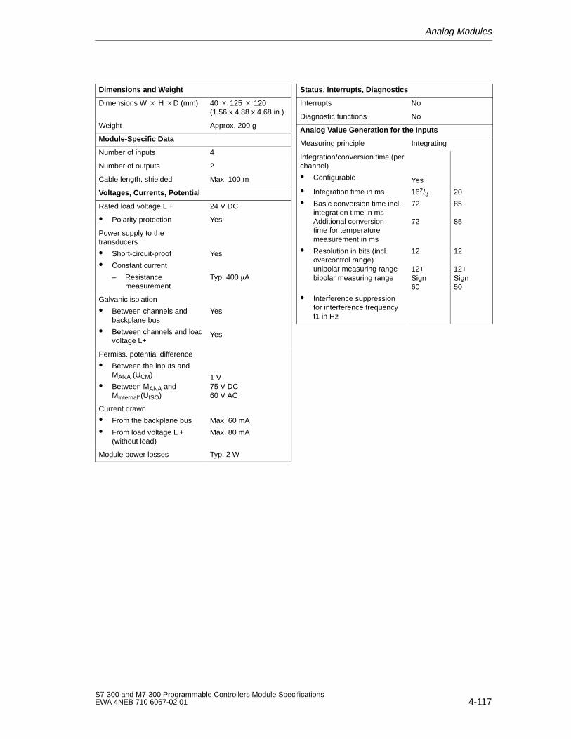
Analog Modules
4-117S7-300 and M7-300 Programmable Controllers Module SpecificationsEWA 4NEB 710 6067-02 01
Dimensions and W eight
Dimensions W H D (mm) 40 125 120(1.56 x 4.88 x 4.68 in.)
Weight Approx. 200 g
Module-Specific Data
Number of inputs 4
Number of outputs 2
Cable length, shielded Max. 100 m
Voltages, Currents, Potential
Rated load voltage L + 24 V DC
Polarity protection Yes
Power supply to thetransducers
Short-circuit-proof
Constant current
– Resistancemeasurement
Yes
Typ. 400 A
Galvanic isolation
Between channels andbackplane bus
Between channels and loadvoltage L+
Yes
Yes
Permiss. potential difference
Between the inputs andMANA (UCM)
Between MANA and Minternal-(UISO)
1 V75 V DC60 V AC
Current drawn
From the backplane bus
From load voltage L + (without load)
Max. 60 mA
Max. 80 mA
Module power losses Typ. 2 W
Status, Interrupts, Diagnostics
Interrupts No
Diagnostic functions No
Analog V alue Generation for the Inputs
Measuring principle Integrating
Integration/conversion time (perchannel)
Configurable
Integration time in ms
Basic conversion time incl.integration time in msAdditional conversiontime for temperaturemeasurement in ms
Resolution in bits (incl.overcontrol range)unipolar measuring rangebipolar measuring range
Interference suppressionfor interference frequencyf1 in Hz
Yes
162/372
72
12
12+Sign60
20
85
85
12
12+Sign50
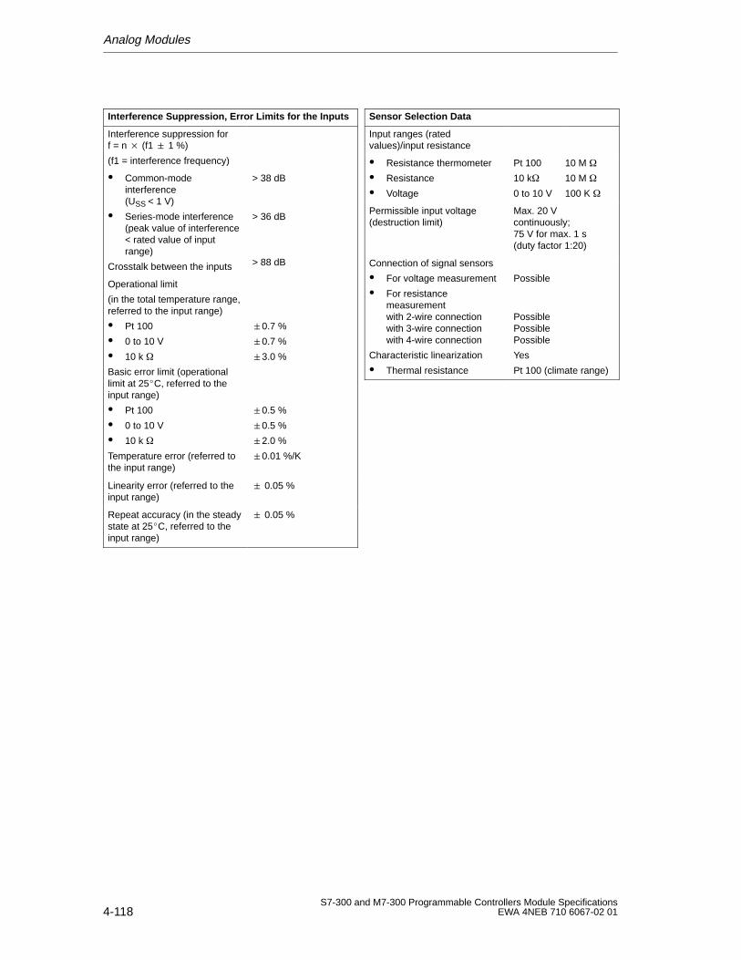
Analog Modules
4-118S7-300 and M7-300 Programmable Controllers Module Specifications
EWA 4NEB 710 6067-02 01
Interference Suppression, Error Limits for the Inputs
Interference suppression forf = n (f1 1 %)
(f1 = interference frequency)
Common-modeinterference(USS < 1 V)
Series-mode interference(peak value of interference< rated value of inputrange)
Crosstalk between the inputs
> 38 dB
> 36 dB
> 88 dB
Operational limit
(in the total temperature range,referred to the input range)
Pt 100
0 to 10 V
10 k
Basic error limit (operationallimit at 25C, referred to theinput range)
Pt 100
0 to 10 V
10 k
Temperature error (referred tothe input range)
0.7 %
0.7 %
3.0 %
0.5 %
0.5 %
2.0 %
0.01 %/K
Linearity error (referred to theinput range)
0.05 %
Repeat accuracy (in the steadystate at 25C, referred to theinput range)
0.05 %
Sensor Selection Data
Input ranges (ratedvalues)/input resistance
Resistance thermometer
Resistance
Voltage
Pt 100 10 M
10 k 10 M
0 to 10 V 100 K
Permissible input voltage(destruction limit)
Max. 20 V continuously;75 V for max. 1 s(duty factor 1:20)
Connection of signal sensors
For voltage measurement
For resistancemeasurementwith 2-wire connectionwith 3-wire connectionwith 4-wire connection
Characteristic linearization
Thermal resistance
Possible
PossiblePossiblePossible
Yes
Pt 100 (climate range)
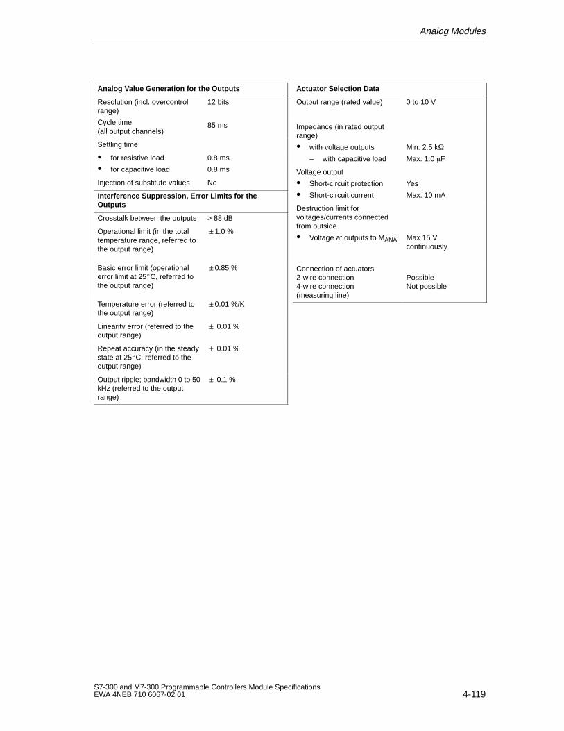
Analog Modules
4-119S7-300 and M7-300 Programmable Controllers Module SpecificationsEWA 4NEB 710 6067-02 01
Analog V alue Generation for the Outputs
Resolution (incl. overcontrolrange)
Cycle time (all output channels)
12 bits
85 ms
Settling time
for resistive load
for capacitive load
0.8 ms
0.8 ms
Injection of substitute values No
Interference Suppression, Error Limits for theOutputs
Crosstalk between the outputs > 88 dB
Operational limit (in the totaltemperature range, referred tothe output range)
1.0 %
Basic error limit (operationalerror limit at 25C, referred tothe output range)
0.85 %
Temperature error (referred tothe output range)
0.01 %/K
Linearity error (referred to theoutput range)
0.01 %
Repeat accuracy (in the steadystate at 25C, referred to theoutput range)
0.01 %
Output ripple; bandwidth 0 to 50kHz (referred to the outputrange)
0.1 %
Actuator Selection Data
Output range (rated value) 0 to 10 V
Impedance (in rated outputrange)
with voltage outputs
– with capacitive load
Min. 2.5 k
Max. 1.0 F
Voltage output
Short-circuit protection
Short-circuit current
Yes
Max. 10 mA
Destruction limit forvoltages/currents connectedfrom outside
Voltage at outputs to MANA Max 15 V continuously
Connection of actuators2-wire connection4-wire connection(measuring line)
PossibleNot possible
Analog Modules
4-120S7-300 and M7-300 Programmable Controllers Module Specifications
EWA 4NEB 710 6067-02 01
4.11.1 Starting Up the SM 334
STEP 7 V 4.0
Analog input/output module SM 334 AI4/AO212Bit is only contained in themodule catalog of STEP 7 V 4.0 and higher.
Configuration
You set the prescribed function parameters of the SM 334:
with STEP 7 before start-up (see User Manual STEP 7 or the online help inSTEP 7 ).
in the user program with SFCs (see Reference Manual STEP 7 System andStandard Functions).
Default Settings
The SM 334 has the following default settings:
for the analog inputs: Pt 100 climate range
for the analog outputs: 0 to 10 V
Wiring Versions
You can wire the channels of the SM 334 for the following combinations:
Channels 0and 1
2Pt 100
2resistance
Channels 2and 3
2voltage
2resistance
2Pt 100
1Pt 100, 1voltage
1resistance, 1voltage
Unused Input Channels
You must short-circuit unused channels of the SM 334 and connect them to MANA.You thus obtain optimum interference protection for your analog module. Youshould also deactivate unused channels during configuration with STEP 7 (seeSection 4.3.4 in the Module Specifications Reference Manual), in order to reducethe cycle time of the module.
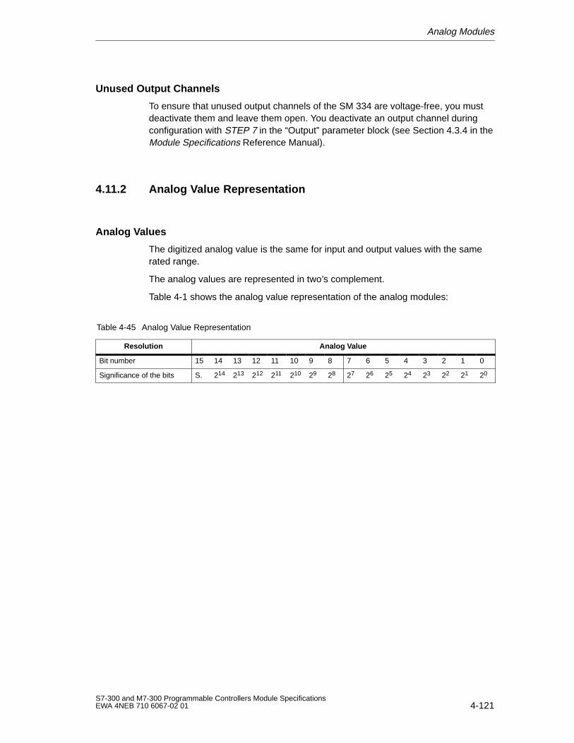
Analog Modules
4-121S7-300 and M7-300 Programmable Controllers Module SpecificationsEWA 4NEB 710 6067-02 01
Unused Output Channels
To ensure that unused output channels of the SM 334 are voltage-free, you mustdeactivate them and leave them open. You deactivate an output channel duringconfiguration with STEP 7 in the “Output” parameter block (see Section 4.3.4 in theModule Specifications Reference Manual).
4.11.2 Analog Value Representation
Analog Values
The digitized analog value is the same for input and output values with the samerated range.
The analog values are represented in two’s complement.
Table 4-1 shows the analog value representation of the analog modules:
Table 4-45 Analog Value Representation
Resolution Analog Value
Bit number 15 14 13 12 11 10 9 8 7 6 5 4 3 2 1 0
Significance of the bits S. 214 213 212 211 210 29 28 27 26 25 24 23 22 21 20
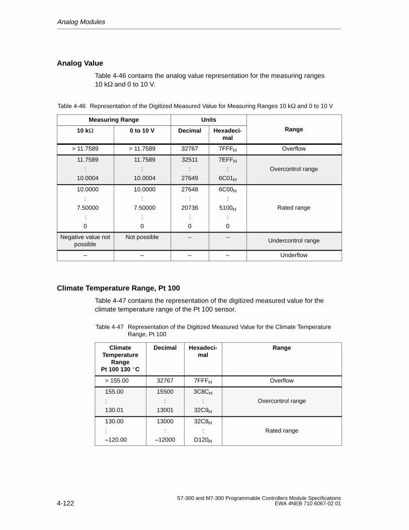
Analog Modules
4-122S7-300 and M7-300 Programmable Controllers Module Specifications
EWA 4NEB 710 6067-02 01
Analog Value
Table 4-46 contains the analog value representation for the measuring ranges10 k and 0 to 10 V.
Table 4-46 Representation of the Digitized Measured Value for Measuring Ranges 10 k and 0 to 10 V
Measuring Range Units
10 k 0 to 10 V Decimal Hexadeci-mal
Range
> 11.7589 > 11.7589 32767 7FFFH Overflow
11.7589
:
10.0004
11.7589
:
10.0004
32511
:
27649
7EFFH
:
6C01H
Overcontrol range
10.0000
:
7.50000
:
0
10.0000
:
7.50000
:
0
27648
:
20736
:
0
6C00H
:
5100H
:
0
Rated range
Negative value notpossible
Not possible – –Undercontrol range
– – – – Underflow
Climate Temperature Range, Pt 100
Table 4-47 contains the representation of the digitized measured value for theclimate temperature range of the Pt 100 sensor.
Table 4-47 Representation of the Digitized Measured Value for the Climate TemperatureRange, Pt 100
ClimateTemperature
RangePt 100 130 C
Decimal Hexadeci-mal
Range
> 155.00 32767 7FFFH Overflow
155.00
:
130.01
15500
:
13001
3C8CH
:
32C9H
Overcontrol range
130.00
:
–120.00
13000
:
–12000
32C8H
:
D120H
Rated range
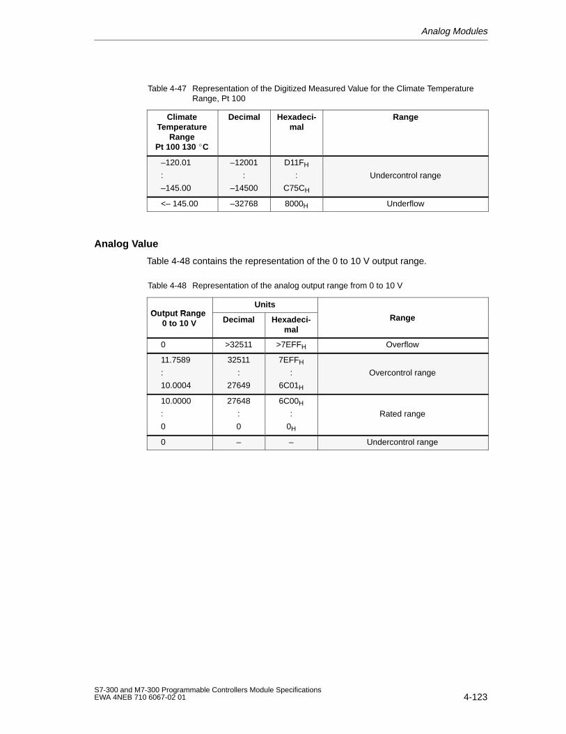
Analog Modules
4-123S7-300 and M7-300 Programmable Controllers Module SpecificationsEWA 4NEB 710 6067-02 01
Table 4-47 Representation of the Digitized Measured Value for the Climate TemperatureRange, Pt 100
ClimateTemperature
RangePt 100 130 C
RangeHexadeci-mal
Decimal
–120.01
:
–145.00
–12001
:
–14500
D11FH
:
C75CH
Undercontrol range
<– 145.00 –32768 8000H Underflow
Analog Value
Table 4-48 contains the representation of the 0 to 10 V output range.
Table 4-48 Representation of the analog output range from 0 to 10 V
Output RangeUnits
Output Range 0 to 10 V Decimal Hexadeci-
malRange
0 >32511 >7EFFH Overflow
11.7589
:
10.0004
32511
:
27649
7EFFH
:
6C01H
Overcontrol range
10.0000
:
0
27648
:
0
6C00H
:
0H
Rated range
0 – – Undercontrol range
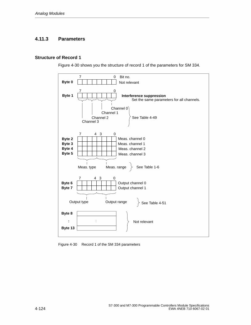
Analog Modules
4-124S7-300 and M7-300 Programmable Controllers Module Specifications
EWA 4NEB 710 6067-02 01
4.11.3 Parameters
Structure of Record 1
Figure 4-30 shows you the structure of record 1 of the parameters for SM 334.
Byte 07 0 Bit no.
Byte 1
Channel 0Channel 1
Channel 3Channel 2
Interference suppression
Byte 2Byte 3Byte 4Byte 5
7 04 3Meas. channel 0
Meas. channel 2Meas. channel 1
Meas. channel 3
Meas. rangeMeas. type
7 0
Not relevant
:
Byte 8
:
Byte 13
Byte 6Byte 7
7 04 3Output channel 0Output channel 1
Output rangeOutput type
See Table 1-6
See Table 4-51
See Table 4-49
Set the same parameters for all channels.
Not relevant
Figure 4-30 Record 1 of the SM 334 parameters
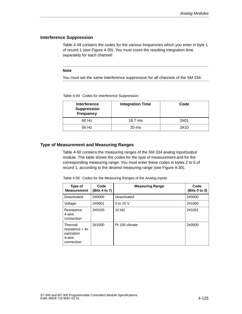
Analog Modules
4-125S7-300 and M7-300 Programmable Controllers Module SpecificationsEWA 4NEB 710 6067-02 01
Interference Suppression
Table 4-49 contains the codes for the various frequencies which you enter in byte 1of record 1 (see Figure 4-30). You must count the resulting integration timeseparately for each channel!
Note
You must set the same interference suppression for all channels of the SM 334.
Table 4-49 Codes for Interference Suppression
Interference Suppression
Frequency
Integration Time Code
60 Hz 16.7 ms 2#01
50 Hz 20 ms 2#10
Type of Measurement and Measuring Ranges
Table 4-50 contains the measuring ranges of the SM 334 analog input/outputmodule. The table shows the codes for the type of measurement and for thecorresponding measuring range. You must enter these codes in bytes 2 to 5 ofrecord 1, according to the desired measuring range (see Figure 4-30).
Table 4-50 Codes for the Measuring Ranges of the Analog Inputs
Type ofMeasurement
Code (Bits 4 to 7)
Measuring Range Code (Bits 0 to 3)
Deactivated 2#0000 Deactivated 2#0000
Voltage 2#0001 0 to 10 V 2#1000
Resistance4-wireconnection
2#0100 10 k 2#1001
Thermalresistance + linearization4-wireconnection
2#1000 Pt 100 climate 2#0000
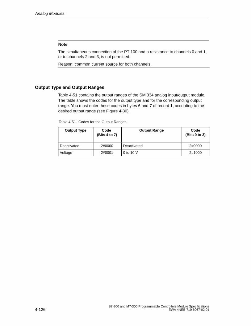
Analog Modules
4-126S7-300 and M7-300 Programmable Controllers Module Specifications
EWA 4NEB 710 6067-02 01
Note
The simultaneous connection of the PT 100 and a resistance to channels 0 and 1,or to channels 2 and 3, is not permitted.
Reason: common current source for both channels.
Output Type and Output Ranges
Table 4-51 contains the output ranges of the SM 334 analog input/output module.The table shows the codes for the output type and for the corresponding outputrange. You must enter these codes in bytes 6 and 7 of record 1, according to thedesired output range (see Figure 4-30).
Table 4-51 Codes for the Output Ranges
Output Type Code (Bits 4 to 7)
Output Range Code(Bits 0 to 3)
Deactivated 2#0000 Deactivated 2#0000
Voltage 2#0001 0 to 10 V 2#1000
5-1S7-300 and M7-300 Programmable Controllers Module SpecificationsEWA 4NEB 710 6067-02 01
Other Signal Modules
Other Signal Modules?
In addition to the digital and analog modules further signal modules are available :
a simulator module for simulating inputs and outputs and
a dummy module for reserving an installation slot.
an SM 338 POS input module to register the SSI encoder values
In this chapter, you will find the technical specifications for these signal modulesand a description of their function.
Contents
The following signal modules are described in this chapter:
Section Contents Page
5.1 Simulator Module SM 374; IN/OUT 16 5-2
5.2 Dummy Module DM 370 5-4
5.3 SM 338 POS input module 5-7
5
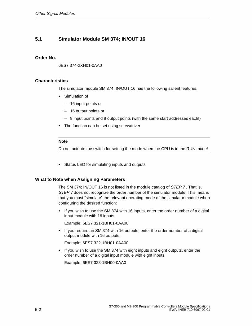
Other Signal Modules
5-2S7-300 and M7-300 Programmable Controllers Module Specifications
EWA 4NEB 710 6067-02 01
5.1 Simulator Module SM 374; IN/OUT 16
Order No.
6ES7 374-2XH01-0AA0
Characteristics
The simulator module SM 374; IN/OUT 16 has the following salient features:
Simulation of
– 16 input points or
– 16 output points or
– 8 input points and 8 output points (with the same start addresses each!)
The function can be set using screwdriver
Note
Do not actuate the switch for setting the mode when the CPU is in the RUN mode!
Status LED for simulating inputs and outputs
What to Note when Assigning Parameters
The SM 374; IN/OUT 16 is not listed in the module catalog of STEP 7 . That is,STEP 7 does not recognize the order number of the simulator module. This meansthat you must “simulate” the relevant operating mode of the simulator module whenconfiguring the desired function:
If you wish to use the SM 374 with 16 inputs, enter the order number of a digitalinput module with 16 inputs.
Example: 6ES7 321-1BH01-0AA00
If you require an SM 374 with 16 outputs, enter the order number of a digitaloutput module with 16 outputs.
Example: 6ES7 322-1BH01-0AA00
If you wish to use the SM 374 with eight inputs and eight outputs, enter theorder number of a digital input module with eight inputs.
Example: 6ES7 323-1BH00-0AA0
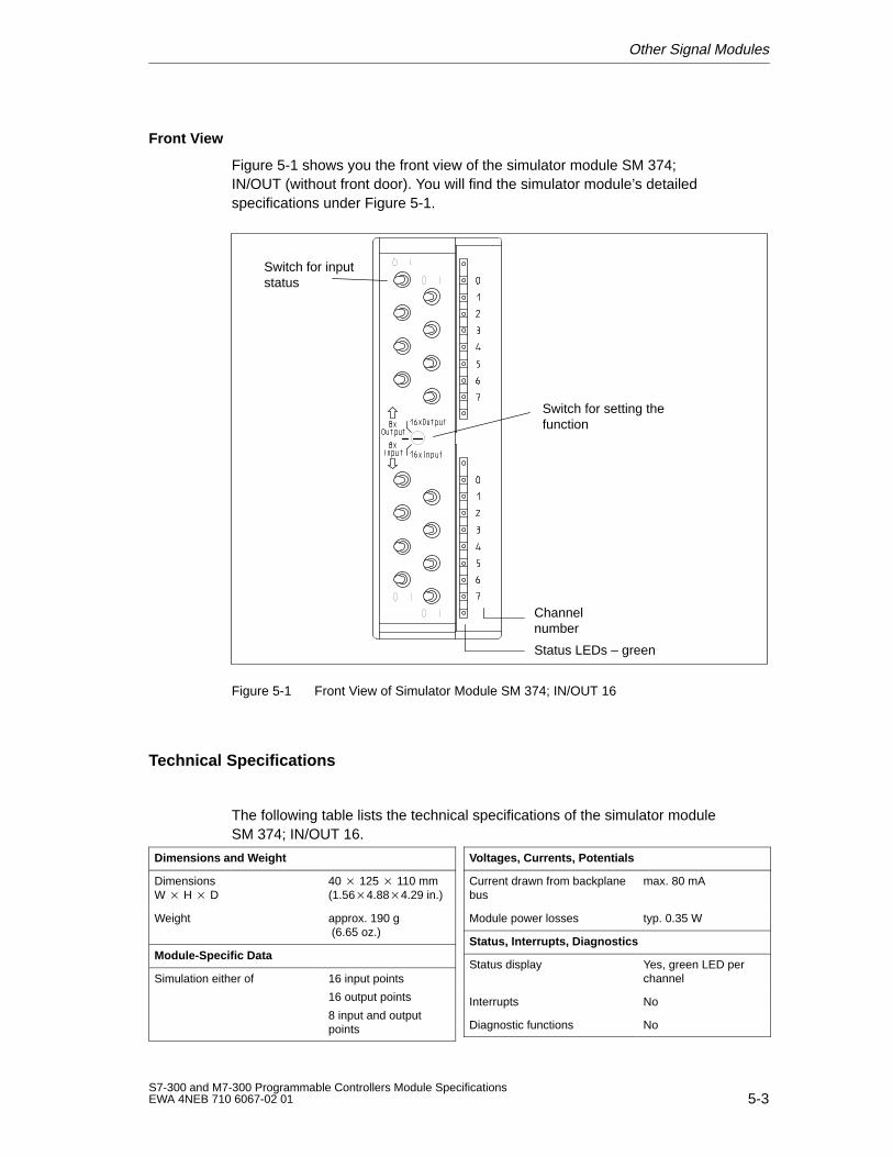
Other Signal Modules
5-3S7-300 and M7-300 Programmable Controllers Module SpecificationsEWA 4NEB 710 6067-02 01
Front View
Figure 5-1 shows you the front view of the simulator module SM 374; IN/OUT (without front door). You will find the simulator module’s detailedspecifications under Figure 5-1.
Status LEDs – green
Channelnumber
Switch for inputstatus
Switch for setting thefunction
Figure 5-1 Front View of Simulator Module SM 374; IN/OUT 16
Technical Specifications
The following table lists the technical specifications of the simulator moduleSM 374; IN/OUT 16.
Dimensions and Weight
DimensionsW H D
40 125 110 mm(1.564.884.29 in.)
Weight approx. 190 g (6.65 oz.)
Module-Specific Data
Simulation either of 16 input points
16 output points
8 input and outputpoints
Voltages, Currents, Potentials
Current drawn from backplanebus
max. 80 mA
Module power losses typ. 0.35 W
Status, Interrupts, Diagnostics
Status display Yes, green LED perchannel
Interrupts No
Diagnostic functions No
Other Signal Modules
5-4S7-300 and M7-300 Programmable Controllers Module Specifications
EWA 4NEB 710 6067-02 01
5.2 Dummy Module DM 370
Order No.
6ES7 370-0AA01-0AA0
Characteristics
The dummy module DM 370 reserves a slot for non-configured digital modules andinterface modules. If you replace the dummy module by another S7-300 module,the mechanical configuration and the address assignment of the overallconfiguration are retained.
Special Features
The dummy module can be used as a placeholder for:
Interface modules (without reserving address space)
Non-configured digital modules (reserving address space)
Modules occupying 2 slots. In this case, you must plug in two dummy modules with the dummy module inslot “x” reserving the address space and the dummy module in slot “x + 1”reserving no address space (see also Table 5-1). Note: No more than 8modules (SM/FM/CP) may be plugged into a module rack. For example, if youreserve a slot for a module of 80 mm width using 2 dummy modules, you canplug in only 6 other modules (SM/FM/CP).
Configuration with STEP 7
Use STEP 7 to configure the dummy module only if you are using the module toreserve the slot for a parameterized signal module. If the module is to reserve theslot for an interface module, you need not configure the module with STEP 7 .
Configuration for ET 200M
If you use the dummy module DM 370 in an ET 200M setup with active busmodules, you must configure an input or output address range of 0 bytes for thedummy module (see also Table 5-1).
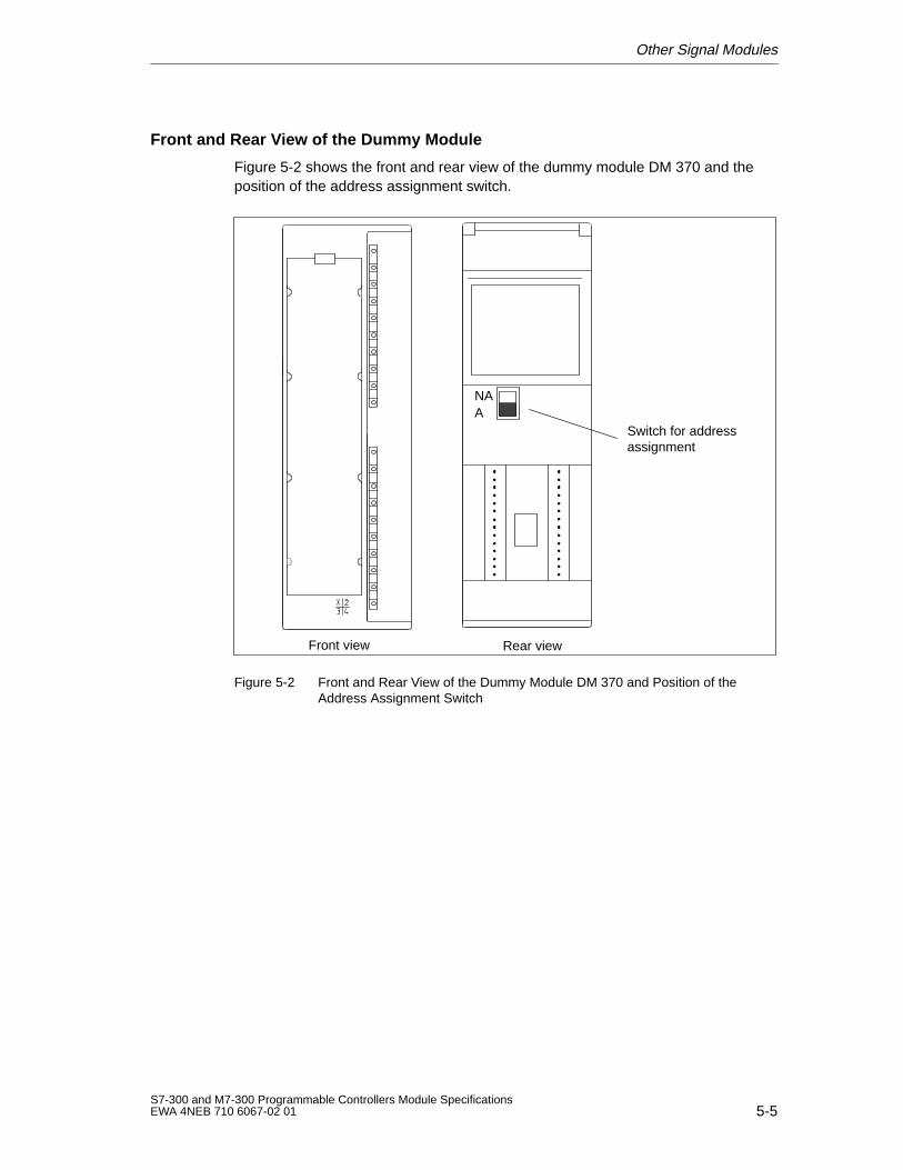
Other Signal Modules
5-5S7-300 and M7-300 Programmable Controllers Module SpecificationsEWA 4NEB 710 6067-02 01
Front and Rear View of the Dummy Module
Figure 5-2 shows the front and rear view of the dummy module DM 370 and theposition of the address assignment switch.
NAA
Switch for addressassignment
Rear viewFront view
Figure 5-2 Front and Rear View of the Dummy Module DM 370 and Position of theAddress Assignment Switch
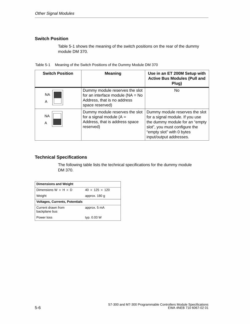
Other Signal Modules
5-6S7-300 and M7-300 Programmable Controllers Module Specifications
EWA 4NEB 710 6067-02 01
Switch Position
Table 5-1 shows the meaning of the switch positions on the rear of the dummymodule DM 370.
Table 5-1 Meaning of the Switch Positions of the Dummy Module DM 370
Switch Position Meaning Use in an ET 200M Setup withActive Bus Modules (Pull and
Plug)
A
NADummy module reserves the slotfor an interface module (NA = NoAddress, that is no addressspace reserved)
No
A
NADummy module reserves the slotfor a signal module (A =Address, that is address spacereserved)
Dummy module reserves the slotfor a signal module. If you usethe dummy module for an “emptyslot”, you must configure the“empty slot” with 0 bytesinput/output addresses.
Technical Specifications
The following table lists the technical specifications for the dummy moduleDM 370.
Dimensions and Weight
Dimensions W H D 40 125 120
Weight approx. 180 g
Voltages, Currents, Potentials
Current drawn from backplane bus
approx. 5 mA
Power loss typ. 0.03 W
Other Signal Modules
5-7S7-300 and M7-300 Programmable Controllers Module SpecificationsEWA 4NEB 710 6067-02 01
5.3 SM 338 POS Input Module
Order Number
6ES7 338-4BC00-0AB0
Characteristics
The SM 338 POS input module is characterized by the following features:
The SM 338 POS input module is an interface between up to three absoluteposition encoders (SSIs) and the CPU of SIMATIC S7.
You edit the encoder values obtained by the SM 338 in your STEP 7 program.
You can respond directly in your process to encoder values in moving systems.
How the SM 338 POS Input Module Works
The SM 338 POS input module makes available the SSI position encoder status inthe process input range to the CPU. It is also possible to freeze the SSI positionencoder statuses via two module-specific digital inputs. This freeze function makesit possible to provide a solution for other time-critical position detectionapplications.
Supported Encoder Types
The following encoder types are supported:
The absolute position encoder (SSI) with 13 bits
The absolute position encoder (SSI) with 21 bits
The absolute position encoder (SSI) with 25 bits
Data Formats
The data formats supported are gray code and binary code.
Parameterization
You parameterize the SM 338 with HWConfig in STEP 7 (as of Version 4.1).
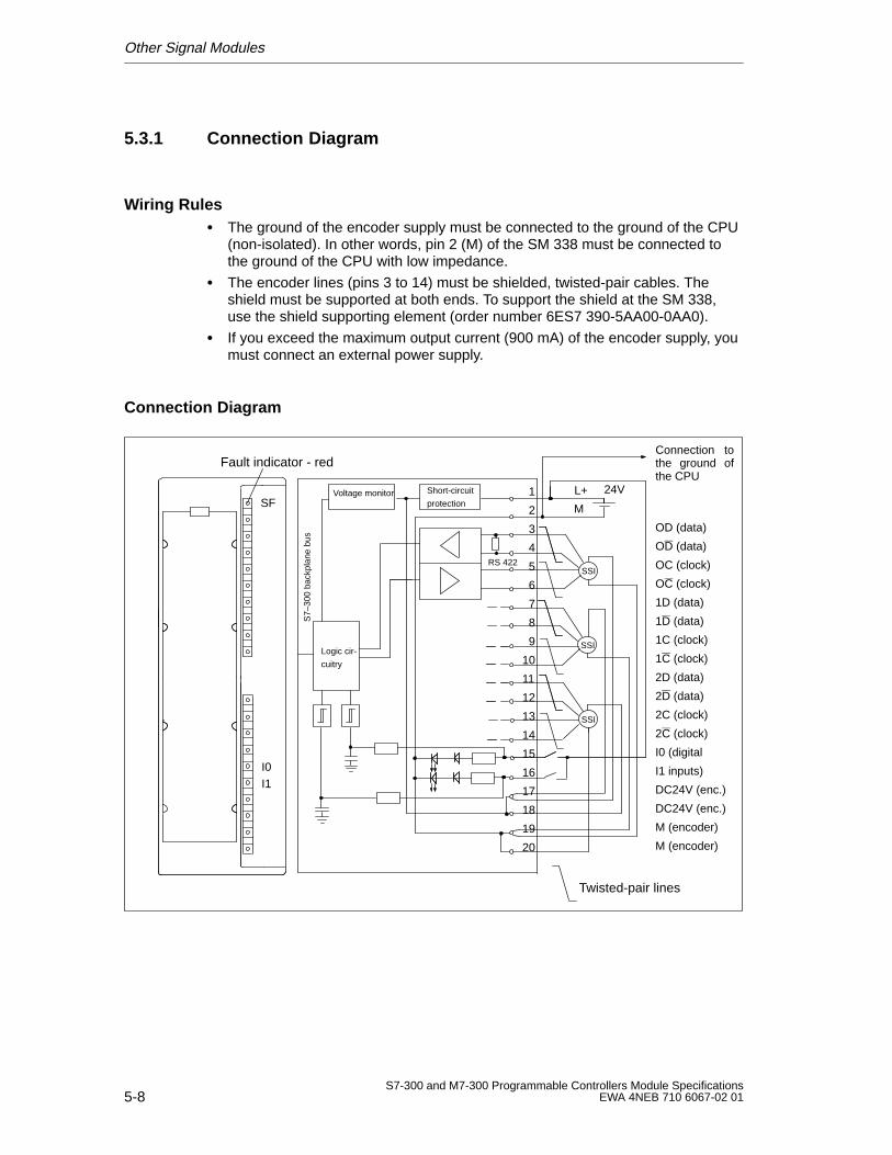
Other Signal Modules
5-8S7-300 and M7-300 Programmable Controllers Module Specifications
EWA 4NEB 710 6067-02 01
5.3.1 Connection Diagram
Wiring Rules The ground of the encoder supply must be connected to the ground of the CPU
(non-isolated). In other words, pin 2 (M) of the SM 338 must be connected tothe ground of the CPU with low impedance.
The encoder lines (pins 3 to 14) must be shielded, twisted-pair cables. Theshield must be supported at both ends. To support the shield at the SM 338,use the shield supporting element (order number 6ES7 390-5AA00-0AA0).
If you exceed the maximum output current (900 mA) of the encoder supply, youmust connect an external power supply.
Connection Diagram
Fault indicator - red
1
2
3
4
5
6
7
8
9
10
11
12
13
14
15
16
17
18
19
20
L+ 24V
OD (data)
OD (data)
OC (clock)
OC (clock)
1D (data)
1D (data)
1C (clock)
1C (clock)
2D (data)
2D (data)
2C (clock)
2C (clock)
I0 (digital
I1 inputs)
DC24V (enc.)
DC24V (enc.)
M (encoder)
M (encoder)
SSI
SSI
SSI
Short-circuit
protectionVoltage monitor
SF
S7–
300
back
plan
e bu
s
Logic cir-
cuitry
M
RS 422
Twisted-pair lines
I0I1
Connection tothe ground ofthe CPU
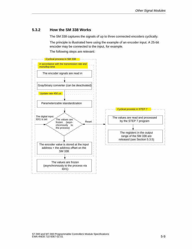
Other Signal Modules
5-9S7-300 and M7-300 Programmable Controllers Module SpecificationsEWA 4NEB 710 6067-02 01
5.3.2 How the SM 338 Works
The SM 338 captures the signals of up to three connected encoders cyclically.
The principle is illustrated here using the example of an encoder input. A 25-bitencoder may be connected to the input, for example.
The following steps are relevant:
The encoder signals are read in
Gray/binary converter (can be deactivated)
Parameterizable standardization
The encoder value is stored at the inputaddress + the address offset on the
SM 338
The values are frozen(asynchronously to the process via
I0/I1)
Update rate 450 s
The values are read and processedby the STEP 7 program
in accordance with the transmission rate andmonoflop time
Cyclical process in STEP 7
Cyclical process in SM 338
The registers in the outputrange of the SM 338 are
released (see Section 5.3.5)
The values arefrozen (asyn-chronously tothe process)
The digital inputI0/I1 is set
Reset
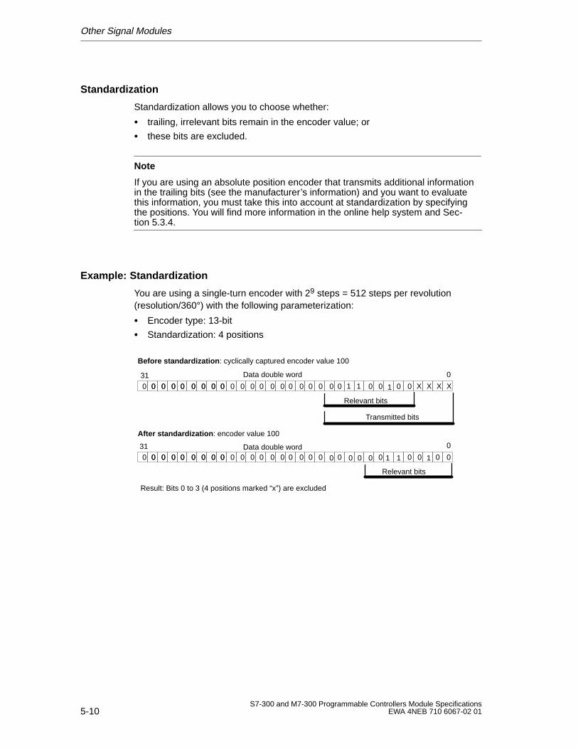
Other Signal Modules
5-10S7-300 and M7-300 Programmable Controllers Module Specifications
EWA 4NEB 710 6067-02 01
Standardization
Standardization allows you to choose whether:
trailing, irrelevant bits remain in the encoder value; or
these bits are excluded.
Note
If you are using an absolute position encoder that transmits additional informationin the trailing bits (see the manufacturer’s information) and you want to evaluatethis information, you must take this into account at standardization by specifyingthe positions. You will find more information in the online help system and Sec-tion 5.3.4.
Example: Standardization
You are using a single-turn encoder with 29 steps = 512 steps per revolution(resolution/360°) with the following parameterization:
Encoder type: 13-bit
Standardization: 4 positions
Before standardization : cyclically captured encoder value 100
0310 0 0 0 0 0 0 00 0 0 0 0 0 0 0 0 0 0 0 0 0 0 00 XXXX0 010 0110 0 00
Transmitted bits
Relevant bits
After standardization : encoder value 100
0310 0 0 0 0 0 0 00 0 0 0 0 0 0 0 0 0 0 0 0 0 0 00 0 010 0110 000 0000
Relevant bits
Data double word
Data double word
Result: Bits 0 to 3 (4 positions marked “x”) are excluded

Other Signal Modules
5-11S7-300 and M7-300 Programmable Controllers Module SpecificationsEWA 4NEB 710 6067-02 01
5.3.3 Freeze Function
The freeze function ”freezes” the module’s current encoder values. A frozenencoder value is indicated by bit 31 being set (output range). The encoder value isretained until the freeze function is terminated. The evaluation of the encodervalues can thus be event-dependent.
Prerequisite for Using the Freeze Function
The freeze function must be enabled and linked to the I0 and/or I1 digital inputs.
During parameterization you specify which I0/I1 digital inputs freeze the encodervalues.
With one digital input you can freeze one, two or three encoder values.
Terminating the Freeze State
The freeze state must be terminated separately for each encoder input. When theuser program acknowledges the transfer of the encoder value, bit 31 is deleted andthe encoder values are updated again.
You write the acknowledgment in the output address of the module with a setacknowledgment bit by directly accessing the SM 338 (T PAB “xyz”).
Freezing is possible again as soon as you have deleted the acknowledgment bit inthe module’s output address.
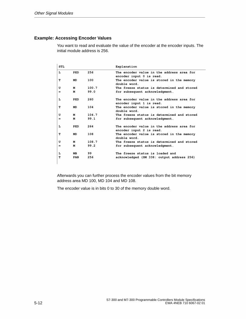
Other Signal Modules
5-12S7-300 and M7-300 Programmable Controllers Module Specifications
EWA 4NEB 710 6067-02 01
Example: Accessing Encoder Values
You want to read and evaluate the value of the encoder at the encoder inputs. Theinitial module address is 256.
STL Explanation
L PED 256
T MD 100
U M 100.7= M 99.0
L PED 260
T MD 104
U M 104.7= M 99.1
L PED 264
T MD 108
U M 108.7= M 99.2
L MB 99T PAB 256
The encoder value in the address area forencoder input 0 is read.The encoder value is stored in the memorydouble word.The freeze status is determined and storedfor subsequent acknowledgment.
The encoder value in the address area forencoder input 1 is read.The encoder value is stored in the memorydouble word.The freeze status is determined and storedfor subsequent acknowledgment.
The encoder value in the address area forencoder input 2 is read.The encoder value is stored in the memorydouble word.The freeze status is determined and storedfor subsequent acknowledgment.
The freeze status is loaded andacknowledged (SM 338: output address 256)
Afterwards you can further process the encoder values from the bit memoryaddress area MD 100, MD 104 and MD 108.
The encoder value is in bits 0 to 30 of the memory double word.
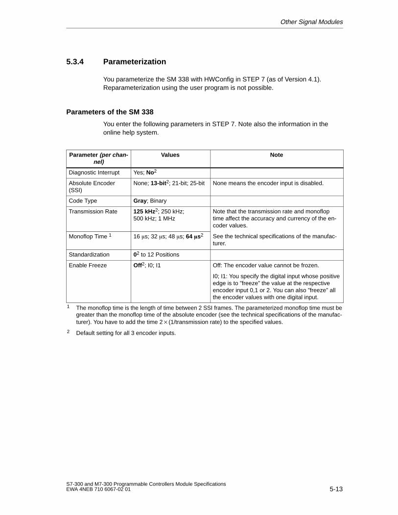
Other Signal Modules
5-13S7-300 and M7-300 Programmable Controllers Module SpecificationsEWA 4NEB 710 6067-02 01
5.3.4 Parameterization
You parameterize the SM 338 with HWConfig in STEP 7 (as of Version 4.1).Reparameterization using the user program is not possible.
Parameters of the SM 338
You enter the following parameters in STEP 7. Note also the information in theonline help system.
Parameter (per chan -nel)
Values Note
Diagnostic Interrupt Yes; No2
Absolute Encoder(SSI)
None; 13-bit 2; 21-bit; 25-bit None means the encoder input is disabled.
Code Type Gray ; Binary
Transmission Rate 125 kHz2; 250 kHz;500 kHz; 1 MHz
Note that the transmission rate and monofloptime affect the accuracy and currency of the en-coder values.
Monoflop Time 1 16 s; 32 s; 48 s; 64 s2 See the technical specifications of the manufac-turer.
Standardization 02 to 12 Positions
Enable Freeze Off2; I0; I1 Off: The encoder value cannot be frozen.
I0; I1: You specify the digital input whose positiveedge is to ”freeze” the value at the respectiveencoder input 0,1 or 2. You can also ”freeze” allthe encoder values with one digital input.
1 The monoflop time is the length of time between 2 SSI frames. The parameterized monoflop time must begreater than the monoflop time of the absolute encoder (see the technical specifications of the manufac-turer). You have to add the time 2(1/transmission rate) to the specified values.
2 Default setting for all 3 encoder inputs.
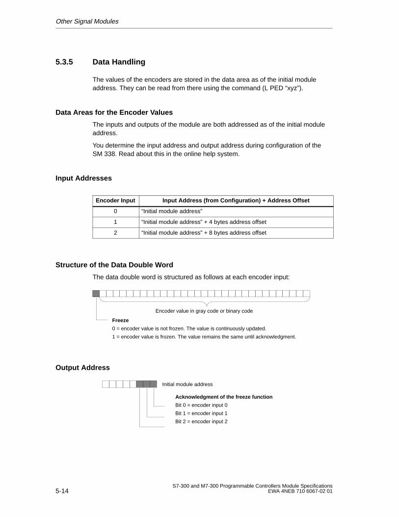
Other Signal Modules
5-14S7-300 and M7-300 Programmable Controllers Module Specifications
EWA 4NEB 710 6067-02 01
5.3.5 Data Handling
The values of the encoders are stored in the data area as of the initial moduleaddress. They can be read from there using the command (L PED “xyz”).
Data Areas for the Encoder Values
The inputs and outputs of the module are both addressed as of the initial moduleaddress.
You determine the input address and output address during configuration of theSM 338. Read about this in the online help system.
Input Addresses
Encoder Input Input Address (from Configuration) + Address Offset
0 “Initial module address”
1 “Initial module address” + 4 bytes address offset
2 “Initial module address” + 8 bytes address offset
Structure of the Data Double Word
The data double word is structured as follows at each encoder input:
Encoder value in gray code or binary code
Freeze
0 = encoder value is not frozen. The value is continuously updated.
1 = encoder value is frozen. The value remains the same until acknowledgment.
Output Address
Acknowledgment of the freeze function
Bit 0 = encoder input 0
Bit 1 = encoder input 1
Bit 2 = encoder input 2
Initial module address
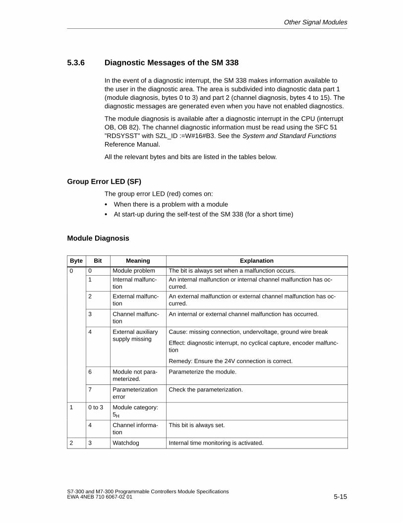
Other Signal Modules
5-15S7-300 and M7-300 Programmable Controllers Module SpecificationsEWA 4NEB 710 6067-02 01
5.3.6 Diagnostic Messages of the SM 338
In the event of a diagnostic interrupt, the SM 338 makes information available tothe user in the diagnostic area. The area is subdivided into diagnostic data part 1(module diagnosis, bytes 0 to 3) and part 2 (channel diagnosis, bytes 4 to 15). Thediagnostic messages are generated even when you have not enabled diagnostics.
The module diagnosis is available after a diagnostic interrupt in the CPU (interruptOB, OB 82). The channel diagnostic information must be read using the SFC 51”RDSYSST” with SZL_ID :=W#16#B3. See the System and Standard FunctionsReference Manual.
All the relevant bytes and bits are listed in the tables below.
Group Error LED (SF)
The group error LED (red) comes on:
When there is a problem with a module
At start-up during the self-test of the SM 338 (for a short time)
Module Diagnosis
Byte Bit Meaning Explanation
0 0 Module problem The bit is always set when a malfunction occurs.0
1 Internal malfunc-tion
An internal malfunction or internal channel malfunction has oc-curred.
2 External malfunc-tion
An external malfunction or external channel malfunction has oc-curred.
3 Channel malfunc-tion
An internal or external channel malfunction has occurred.
4 External auxiliarysupply missing
Cause: missing connection, undervoltage, ground wire break
Effect: diagnostic interrupt, no cyclical capture, encoder malfunc-tion
Remedy: Ensure the 24V connection is correct.
6 Module not para-meterized.
Parameterize the module.
7 Parameterizationerror
Check the parameterization.
1 0 to 3 Module category:5H
4 Channel informa-tion
This bit is always set.
2 3 Watchdog Internal time monitoring is activated.
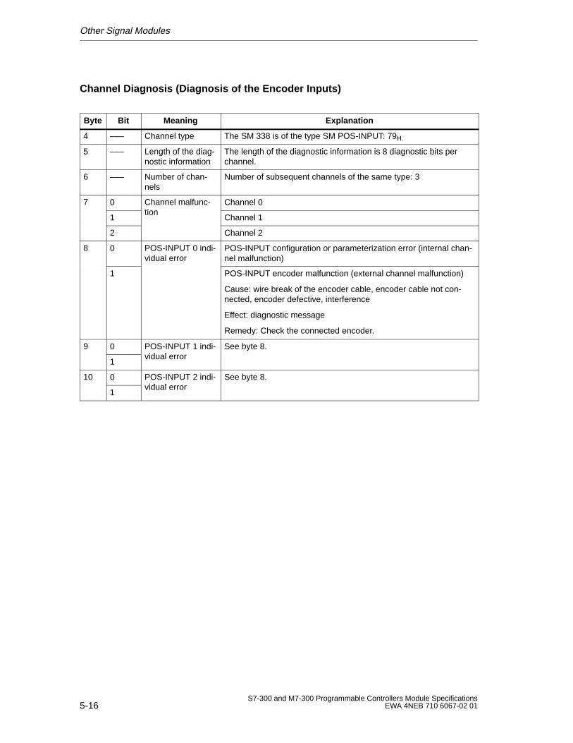
Other Signal Modules
5-16S7-300 and M7-300 Programmable Controllers Module Specifications
EWA 4NEB 710 6067-02 01
Channel Diagnosis (Diagnosis of the Encoder Inputs)
Byte Bit Meaning Explanation
4 ––– Channel type The SM 338 is of the type SM POS-INPUT: 79H.
5 ––– Length of the diag-nostic information
The length of the diagnostic information is 8 diagnostic bits perchannel.
6 ––– Number of chan-nels
Number of subsequent channels of the same type: 3
7 0 Channel malfunc-tion
Channel 0
1tion
Channel 1
2 Channel 2
8 0 POS-INPUT 0 indi-vidual error
POS-INPUT configuration or parameterization error (internal chan-nel malfunction)
1 POS-INPUT encoder malfunction (external channel malfunction)
Cause: wire break of the encoder cable, encoder cable not con-nected, encoder defective, interference
Effect: diagnostic message
Remedy: Check the connected encoder.
9 0 POS-INPUT 1 indi-vidual error
See byte 8.
1vidual error
y
10 0 POS-INPUT 2 indi-vidual error
See byte 8.
1vidual error
y
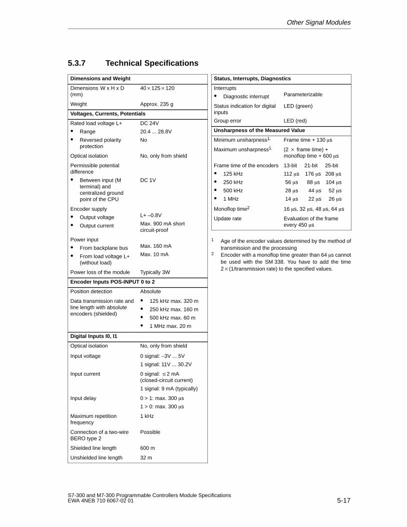
Other Signal Modules
5-17S7-300 and M7-300 Programmable Controllers Module SpecificationsEWA 4NEB 710 6067-02 01
5.3.7 Technical Specifications
Dimensions and Weight
Dimensions W x H x D(mm)
40125120
Weight Approx. 235 g
Voltages, Currents, Potentials
Rated load voltage L+
Range
Reversed polarityprotection
DC 24V
20.4 ... 28.8V
No
Optical isolation No, only from shield
Permissible potentialdifference
Between input (Mterminal) andcentralized groundpoint of the CPU
DC 1V
Encoder supply
Output voltage
Output current
L+ –0.8V
Max. 900 mA shortcircuit-proof
Power input
From backplane bus
From load voltage L+(without load)
Max. 160 mA
Max. 10 mA
Power loss of the module Typically 3W
Encoder Inputs POS-INPUT 0 to 2
Position detection Absolute
Data transmission rate andline length with absoluteencoders (shielded)
125 kHz max. 320 m
250 kHz max. 160 m
500 kHz max. 60 m
1 MHz max. 20 m
Digital Inputs I0, I1
Optical isolation No, only from shield
Input voltage 0 signal: –3V ... 5V
1 signal: 11V ... 30.2V
Input current 0 signal: 2 mA(closed-circuit current)
1 signal: 9 mA (typically)
Input delay 0 > 1: max. 300 s
1 > 0: max. 300 s
Maximum repetitionfrequency
1 kHz
Connection of a two-wireBERO type 2
Possible
Shielded line length 600 m
Unshielded line length 32 m
Status, Interrupts, Diagnostics
Interrupts
Diagnostic interrupt Parameterizable
Status indication for digitalinputs
Group error
LED (green)
LED (red)
Unsharpness of the Measured V alue
Minimum unsharpness1. Frame time + 130s
Maximum unsharpness1. (2 frame time) +monoflop time + 600s
Frame time of the encoders
125 kHz
250 kHz
500 kHz
1 MHz
13-bit 21-bit 25-bit
112 s 176 s 208 s
56 s 88 s 104 s
28 s 44 s 52 s
14 s 22 s 26 s
Monoflop time2 16 s, 32 s, 48 s, 64 s
Update rate Evaluation of the frameevery 450 s
1 Age of the encoder values determined by the method oftransmission and the processing
2 Encoder with a monoflop time greater than 64s cannotbe used with the SM 338. You have to add the time2(1/transmission rate) to the specified values.
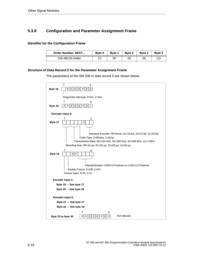
Other Signal Modules
5-18S7-300 and M7-300 Programmable Controllers Module Specifications
EWA 4NEB 710 6067-02 01
5.3.8 Configuration and Parameter Assignment Frame
Identifier for the Configuration Frame
Order Number: 6ES7... Byte 0 Byte 1 Byte 2 Byte 4 Byte 5
338-4BC00-0AB0 C2 8F 00 05 CD
Structure of Data Record 0 for the Parameter Assignment Frame
The parameters of the SM 338 in data record 0 are shown below:
Byte 15
7 0
Diagnostic Interrupt: 0=No; 1=Yes
Byte 17
Absolute Encoder: 00=None; 01=13-bit; 10=21-bit; 11=25-bit
Code Type: 0=Binary; 1=GrayTransmission Rate: 00=125 kHz; 01=250 kHz; 10=500 kHz; 11=1 MHz
000 0 00 0
Byte 16
7 0
000 00 00 1
Encoder input 0:
0
Monoflop time: 00=16 µs; 01=32 µs; 10=48 µs; 11=64 µs
Byte 18
Standardization: 0000=0 Positions to 1100=12 Positions
0
Enable Freeze: 0=Off; 1=On
0
Freeze Input: 0=I0; 1=I1
Encoder input 1:
Byte 19 See byte 17
Byte 20 See byte 18
Encoder input 2:
Byte 21 See byte 17
Byte 22 See byte 18
Byte 23 to byte 30
7 0
7 0
7 0
000 00 00 0 Not relevant
6-1S7-300 and M7-300 Programmable Controllers Module SpecificationsEWA 4NEB 710 6067-02 01
Interface Modules
Interface Modules
In this chapter you will find the technical specifications and characteristic featuresof the interface modules for the S7-300.
Contents
The following interface modules are described in this chapter:
Section Contents Page
6.1 Interface Module IM 360 6-2
6.2 Interface Module IM 361 6-4
6.3 Interface Module IM 365 6-6
6
Interface Modules
6-2S7-300 and M7-300 Programmable Controllers Module Specifications
EWA 4NEB 710 6067-02 01
6.1 Interface Module IM 360
Order No.
6ES7 360-3AA01-0AA0
Characteristics
The interface module IM 360 has the following characteristic features:
Interface for rack 0 of the S7-300
Data transfer from IM 360 to IM 361 over the connecting cable 368
Maximum distance between IM 360 and IM 361 is 10 m (32.8 ft.)
Status and Fault LEDs
The interface module IM 360 has the following status and fault LEDs.
LED Meaning Explanation
SF Group error/fault The LED lights up if
the connecting cable ismissing.
IM 361 is switched off.
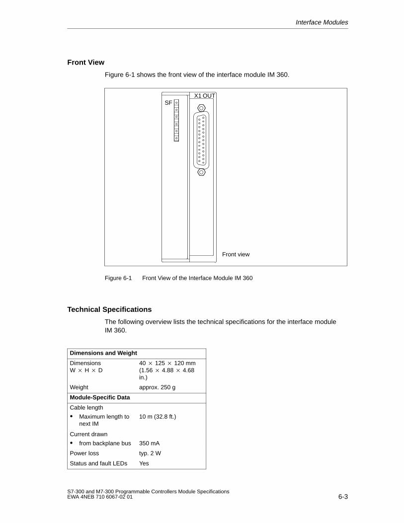
Interface Modules
6-3S7-300 and M7-300 Programmable Controllers Module SpecificationsEWA 4NEB 710 6067-02 01
Front View
Figure 6-1 shows the front view of the interface module IM 360.
Front view
OUTSF
X1
Figure 6-1 Front View of the Interface Module IM 360
Technical Specifications
The following overview lists the technical specifications for the interface moduleIM 360.
Dimensions and Weight
DimensionsW H D
40 125 120 mm(1.56 4.88 4.68in.)
Weight approx. 250 g
Module-Specific Data
Cable length
Maximum length tonext IM
10 m (32.8 ft.)
Current drawn
from backplane bus 350 mA
Power loss typ. 2 W
Status and fault LEDs Yes
Interface Modules
6-4S7-300 and M7-300 Programmable Controllers Module Specifications
EWA 4NEB 710 6067-02 01
6.2 Interface Module IM 361
Order No.
6ES7 361 3CA01-0AA0
Characteristics
The interface module IM 361 has the following characteristic features:
24 VDC power supply
Interface for racks 1 to 3 of the S7-300
Current output via the S7-300 backplane bus max. 0.8 A
Data transfer from the IM 360 to the IM 361 or from the IM 361 to the IM 361via connecting cable 368
Maximum distance between IM 360 and IM 361 is 10 m (32.8 ft.)
Maximum distance between IM 361 and IM 361 is 10 m (32.8 ft.)
Status and Fault LEDs
The interface module IM 361 has the following status and fault LEDs.
LED Meaning Explanation
SF Group error/fault The LED flashes, if
the connecting cable ismissing
the series-connectedIM 361 is switched off
the CPU is in thePOWER OFF state
5 VDC 5 VDC supply for the S7-300backplane bus
–
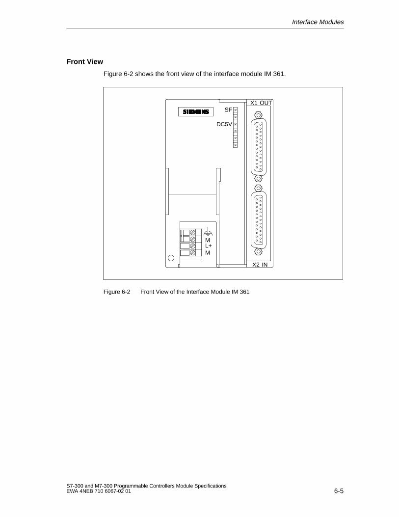
Interface Modules
6-5S7-300 and M7-300 Programmable Controllers Module SpecificationsEWA 4NEB 710 6067-02 01
Front View
Figure 6-2 shows the front view of the interface module IM 361.
OUT
IN
SF
DC5V
X1
X2
ML+M
Figure 6-2 Front View of the Interface Module IM 361
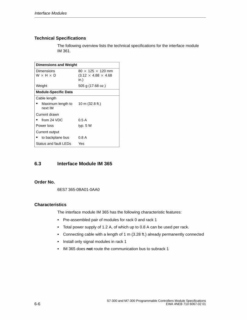
Interface Modules
6-6S7-300 and M7-300 Programmable Controllers Module Specifications
EWA 4NEB 710 6067-02 01
Technical Specifications
The following overview lists the technical specifications for the interface moduleIM 361.
Dimensions and Weight
DimensionsW H D
80 125 120 mm(3.12 4.88 4.68in.)
Weight 505 g (17.68 oz.)
Module-Specific Data
Cable length
Maximum length tonext IM
10 m (32.8 ft.)
Current drawn
from 24 VDC
Power loss
0.5 A
typ. 5 W
Current output
to backplane bus 0.8 A
Status and fault LEDs Yes
6.3 Interface Module IM 365
Order No.
6ES7 365-0BA01-0AA0
Characteristics
The interface module IM 365 has the following characteristic features:
Pre-assembled pair of modules for rack 0 and rack 1
Total power supply of 1.2 A, of which up to 0.8 A can be used per rack.
Connecting cable with a length of 1 m (3.28 ft.) already permanently connected
Install only signal modules in rack 1
IM 365 does not route the communication bus to subrack 1
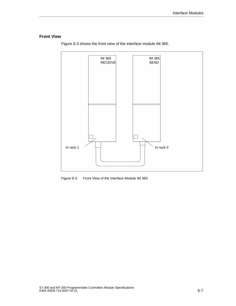
Interface Modules
6-7S7-300 and M7-300 Programmable Controllers Module SpecificationsEWA 4NEB 710 6067-02 01
Front View
Figure 6-3 shows the front view of the interface module IM 365.
In rack 1 In rack 0
IM 365RECEIVE
IM 365SEND
Figure 6-3 Front View of the Interface Module IM 365
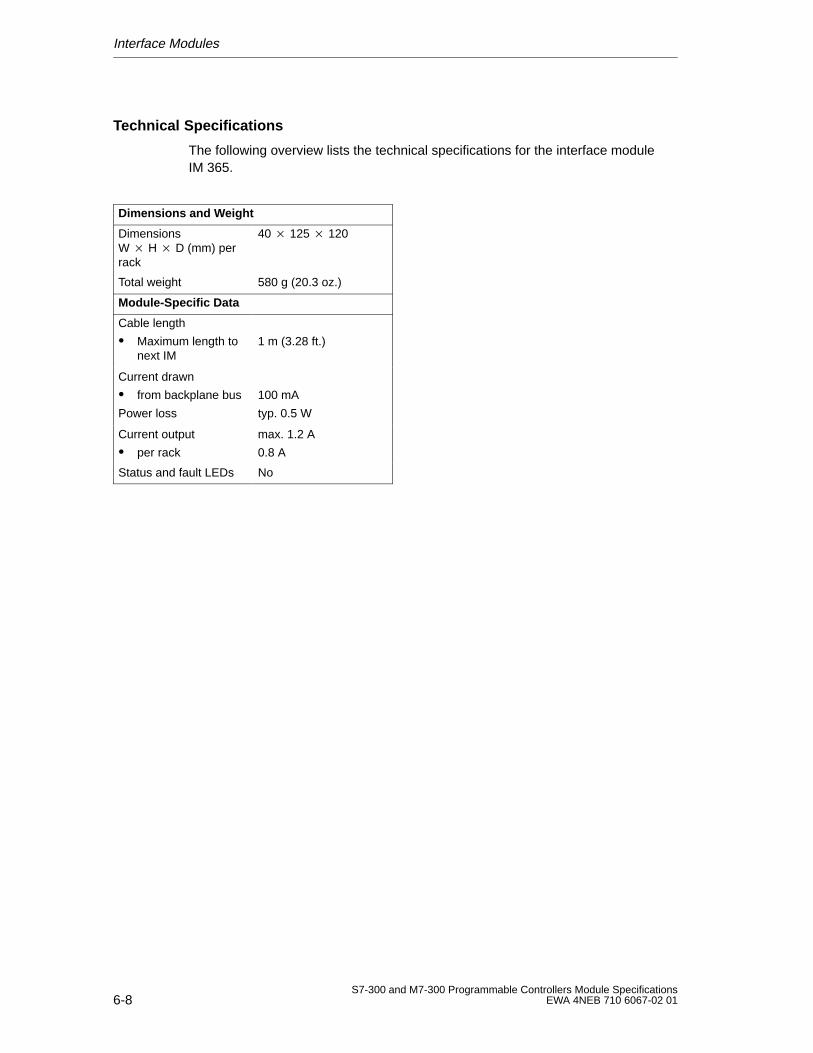
Interface Modules
6-8S7-300 and M7-300 Programmable Controllers Module Specifications
EWA 4NEB 710 6067-02 01
Technical Specifications
The following overview lists the technical specifications for the interface moduleIM 365.
Dimensions and Weight
DimensionsW H D (mm) perrack
40 125 120
Total weight 580 g (20.3 oz.)
Module-Specific Data
Cable length
Maximum length tonext IM
1 m (3.28 ft.)
Current drawn
from backplane bus
Power loss
100 mA
typ. 0.5 W
Current output
per rack
max. 1.2 A
0.8 A
Status and fault LEDs No
7-1S7-300 and M7-300 Programmable Controllers Module SpecificationsEWA 4NEB 710 6067-02 01
RS 485 Repeater
In this Chapter
In this chapter, you will find a detailed description of the RS 485 repeater.
Included in the description are:
The purpose of the RS 485 repeater
The maximum cable lengths possible between two RS 485 repeaters
The functions of the individual operating elements and terminals
Information about grounded and non-grounded operation
Technical specifications and the block diagram
Further Information
You will find further information on the RS 485 repeater in the manuals Hardwareand Installation in the Chapter “Configuring of an MPI or PROFIBUS-DP network”.
Contents
This chapter includes the following sections on the RS 485 repeater:
Section Contents Page
7.1 Application and Properties 7-2
7.2 Technical Specification 7-5
7
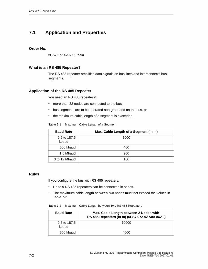
RS 485 Repeater
7-2S7-300 and M7-300 Programmable Controllers Module Specifications
EWA 4NEB 710 6067-02 01
7.1 Application and Properties
Order No.
6ES7 972-0AA00-0XA0
What is an RS 485 Repeater?
The RS 485 repeater amplifies data signals on bus lines and interconnects bussegments.
Application of the RS 485 Repeater
You need an RS 485 repeater if:
more than 32 nodes are connected to the bus
bus segments are to be operated non-grounded on the bus, or
the maximum cable length of a segment is exceeded.
Table 7-1 Maximum Cable Length of a Segment
Baud Rate Max. Cable Length of a Segment (in m)
9.6 to 187.5kbaud
1000
500 kbaud 400
1.5 Mbaud 200
3 to 12 Mbaud 100
Rules
If you configure the bus with RS 485 repeaters:
Up to 9 RS 485 repeaters can be connected in series.
The maximum cable length between two nodes must not exceed the values inTable 7-2.
Table 7-2 Maximum Cable Length between Two RS 485 Repeaters
Baud Rate Max. Cable Length between 2 Nodes with RS 485 Repeaters (in m) (6ES7 972-0AA00-0XA0)
9.6 to 187.5kbaud
10000
500 kbaud 4000
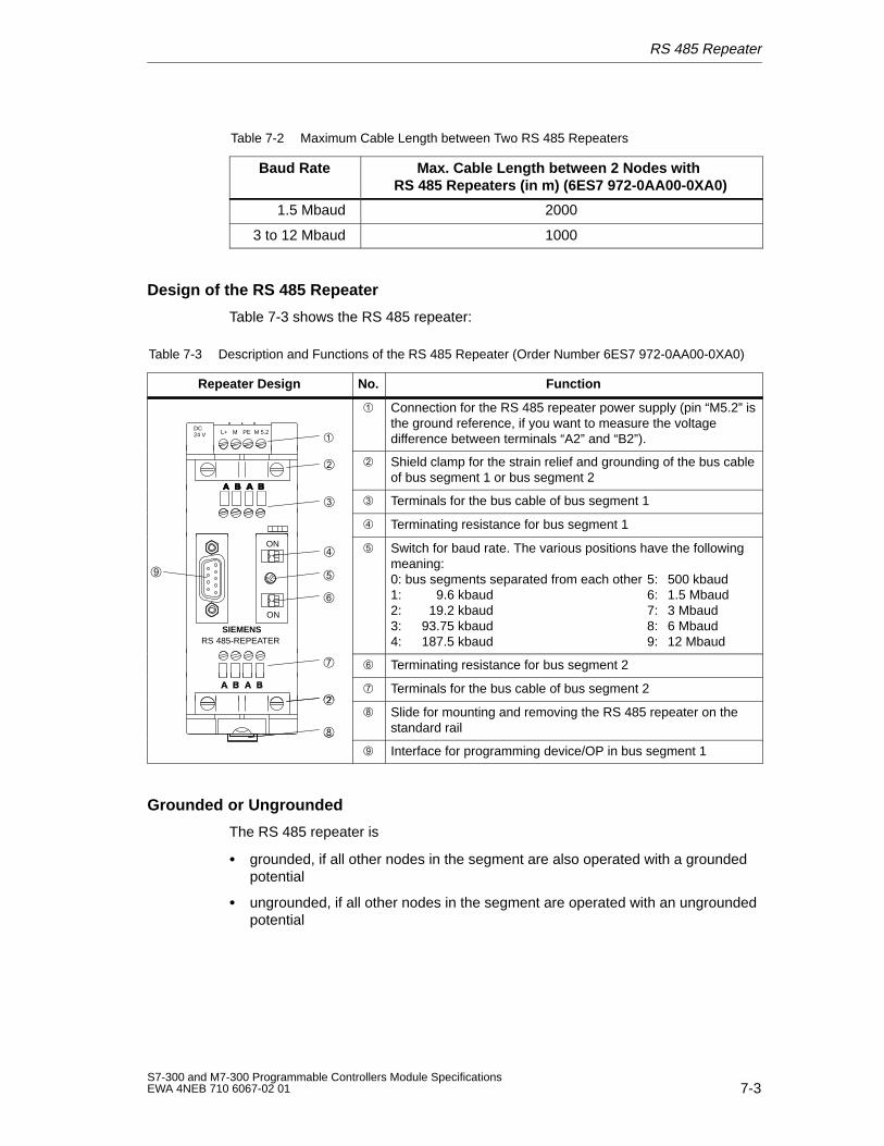
RS 485 Repeater
7-3S7-300 and M7-300 Programmable Controllers Module SpecificationsEWA 4NEB 710 6067-02 01
Table 7-2 Maximum Cable Length between Two RS 485 Repeaters
Baud Rate Max. Cable Length between 2 Nodes with RS 485 Repeaters (in m) (6ES7 972-0AA00-0XA0)
1.5 Mbaud 2000
3 to 12 Mbaud 1000
Design of the RS 485 Repeater
Table 7-3 shows the RS 485 repeater:
Table 7-3 Description and Functions of the RS 485 Repeater (Order Number 6ES7 972-0AA00-0XA0)
Repeater Design No. Function
DC24 V L+ M PE M 5.2
Connection for the RS 485 repeater power supply (pin “M5.2” isthe ground reference, if you want to measure the voltagedifference between terminals “A2” and “B2”).
Shield clamp for the strain relief and grounding of the bus cableof bus segment 1 or bus segment 2
Terminals for the bus cable of bus segment 1
Terminating resistance for bus segment 1
SIEMENSRS 485-REPEATER
ON
ON
Switch for baud rate. The various positions have the followingmeaning:0: bus segments separated from each other 5: 500 kbaud1: 9.6 kbaud 6: 1.5 Mbaud2: 19.2 kbaud 7: 3 Mbaud3: 93.75 kbaud 8: 6 Mbaud4: 187.5 kbaud 9: 12 Mbaud
Terminating resistance for bus segment 2
Terminals for the bus cable of bus segment 2
Slide for mounting and removing the RS 485 repeater on thestandard rail
Interface for programming device/OP in bus segment 1
Grounded or Ungrounded
The RS 485 repeater is
grounded, if all other nodes in the segment are also operated with a groundedpotential
ungrounded, if all other nodes in the segment are operated with an ungroundedpotential
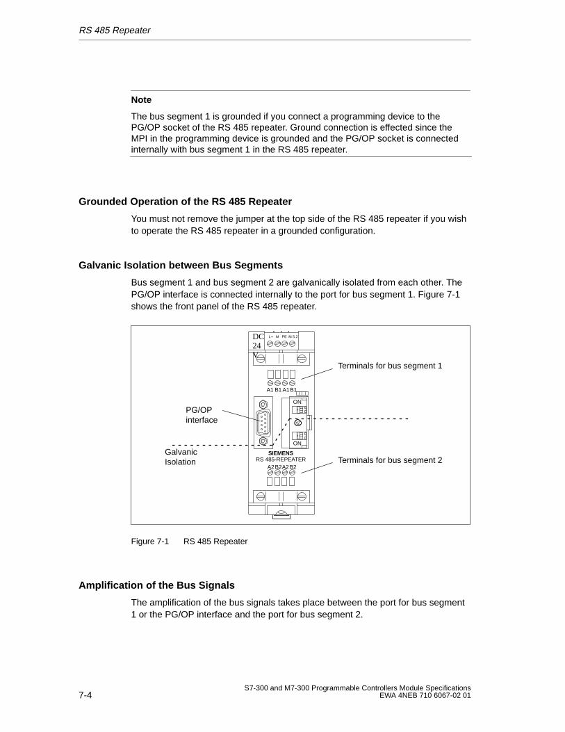
RS 485 Repeater
7-4S7-300 and M7-300 Programmable Controllers Module Specifications
EWA 4NEB 710 6067-02 01
Note
The bus segment 1 is grounded if you connect a programming device to thePG/OP socket of the RS 485 repeater. Ground connection is effected since theMPI in the programming device is grounded and the PG/OP socket is connectedinternally with bus segment 1 in the RS 485 repeater.
Grounded Operation of the RS 485 Repeater
You must not remove the jumper at the top side of the RS 485 repeater if you wishto operate the RS 485 repeater in a grounded configuration.
Galvanic Isolation between Bus Segments
Bus segment 1 and bus segment 2 are galvanically isolated from each other. ThePG/OP interface is connected internally to the port for bus segment 1. Figure 7-1shows the front panel of the RS 485 repeater.
DC24V
L+ M PE M 5.2
A1 B1 A1B1
A2B2A2B2
SIEMENSRS 485-REPEATER
ON
ON
Terminals for bus segment 1
Terminals for bus segment 2
PG/OP interface
GalvanicIsolation
Figure 7-1 RS 485 Repeater
Amplification of the Bus Signals
The amplification of the bus signals takes place between the port for bus segment1 or the PG/OP interface and the port for bus segment 2.
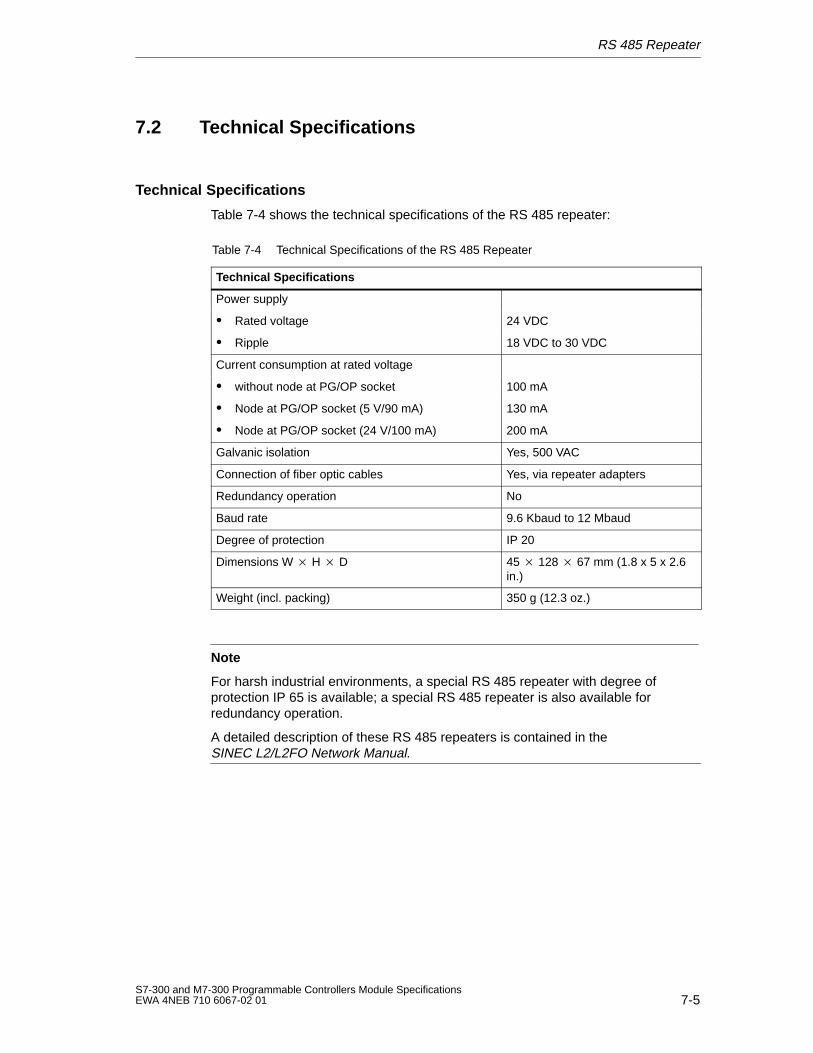
RS 485 Repeater
7-5S7-300 and M7-300 Programmable Controllers Module SpecificationsEWA 4NEB 710 6067-02 01
7.2 Technical Specifications
Technical Specifications
Table 7-4 shows the technical specifications of the RS 485 repeater:
Table 7-4 Technical Specifications of the RS 485 Repeater
Technical Specifications
Power supply
Rated voltage 24 VDC
Ripple 18 VDC to 30 VDC
Current consumption at rated voltage
without node at PG/OP socket 100 mA
Node at PG/OP socket (5 V/90 mA) 130 mA
Node at PG/OP socket (24 V/100 mA) 200 mA
Galvanic isolation Yes, 500 VAC
Connection of fiber optic cables Yes, via repeater adapters
Redundancy operation No
Baud rate 9.6 Kbaud to 12 Mbaud
Degree of protection IP 20
Dimensions W H D 45 128 67 mm (1.8 x 5 x 2.6in.)
Weight (incl. packing) 350 g (12.3 oz.)
Note
For harsh industrial environments, a special RS 485 repeater with degree ofprotection IP 65 is available; a special RS 485 repeater is also available forredundancy operation.
A detailed description of these RS 485 repeaters is contained in the SINEC L2/L2FO Network Manual.
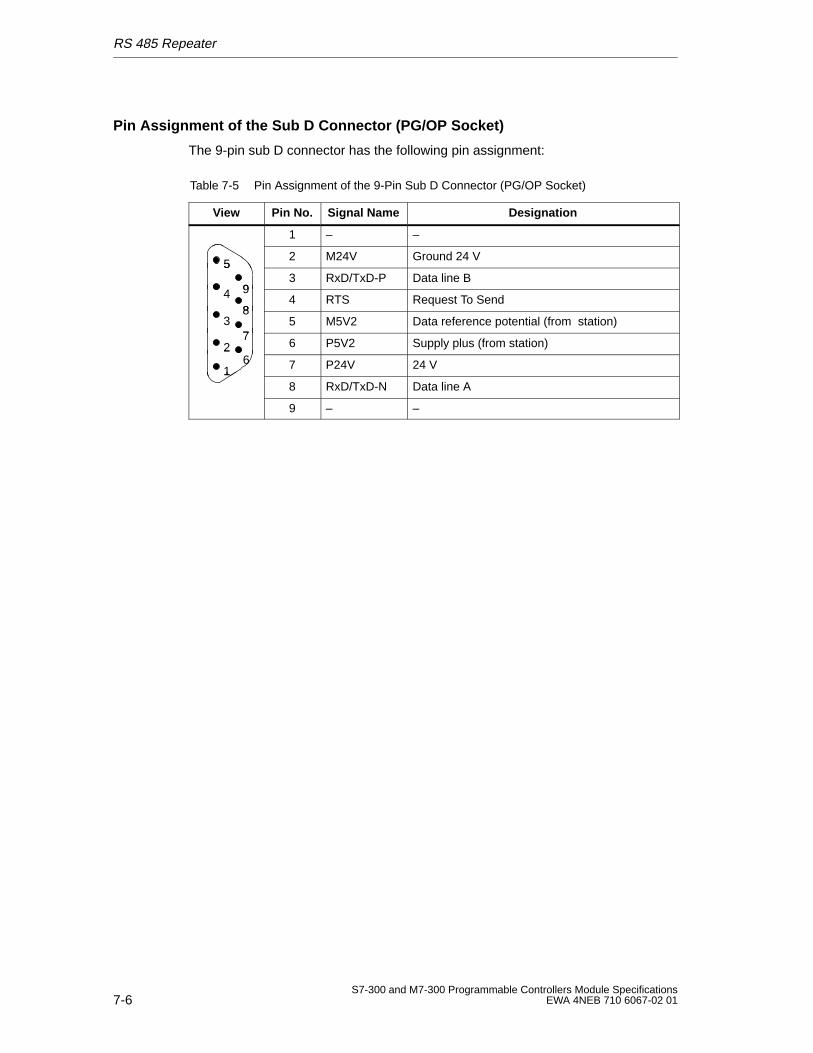
RS 485 Repeater
7-6S7-300 and M7-300 Programmable Controllers Module Specifications
EWA 4NEB 710 6067-02 01
Pin Assignment of the Sub D Connector (PG/OP Socket)
The 9-pin sub D connector has the following pin assignment:
Table 7-5 Pin Assignment of the 9-Pin Sub D Connector (PG/OP Socket)
View Pin No. Signal Name Designation
1 – –
52 M24V Ground 24 V
9
5
43 RxD/TxD-P Data line B
948
4 RTS Request To Send
38
75 M5V2 Data reference potential (from station)
27
66 P5V2 Supply plus (from station)2
16 7 P24V 24 V1
8 RxD/TxD-N Data line A
9 – –
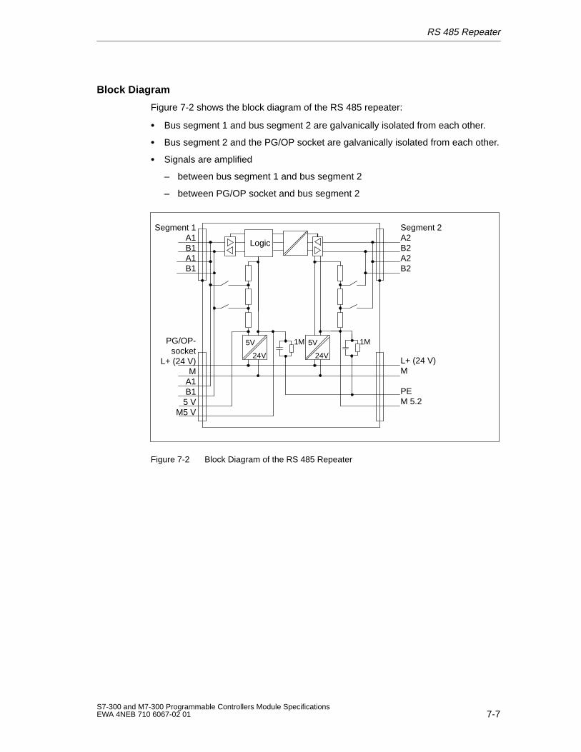
RS 485 Repeater
7-7S7-300 and M7-300 Programmable Controllers Module SpecificationsEWA 4NEB 710 6067-02 01
Block Diagram
Figure 7-2 shows the block diagram of the RS 485 repeater:
Bus segment 1 and bus segment 2 are galvanically isolated from each other.
Bus segment 2 and the PG/OP socket are galvanically isolated from each other.
Signals are amplified
– between bus segment 1 and bus segment 2
– between PG/OP socket and bus segment 2
5V
24V
Segment 2A2B2A2B2
Segment 1A1B1A1B1
PG/OP-socket
L+ (24 V)M
A1B15 V
M5 V
L+ (24 V)M
PEM 5.2
Logic
5V
24V
1M1M
Figure 7-2 Block Diagram of the RS 485 Repeater

RS 485 Repeater
7-8S7-300 and M7-300 Programmable Controllers Module Specifications
EWA 4NEB 710 6067-02 01
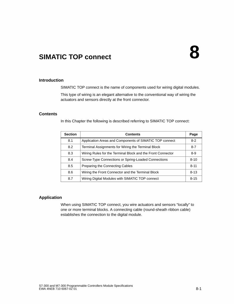
8-1S7-300 and M7-300 Programmable Controllers Module SpecificationsEWA 4NEB 710 6067-02 01
SIMATIC TOP connect
Introduction
SIMATIC TOP connect is the name of components used for wiring digital modules.
This type of wiring is an elegant alternative to the conventional way of wiring theactuators and sensors directly at the front connector.
Contents
In this Chapter the following is described referring to SIMATIC TOP connect:
Section Contents Page
8.1 Application Areas and Components of SIMATIC TOP connect 8-2
8.2 Terminal Assignments for Wiring the Terminal Block 8-7
8.3 Wiring Rules for the Terminal Block and the Front Connector 8-9
8.4 Screw-Type Connections or Spring-Loaded Connections 8-10
8.5 Preparing the Connecting Cables 8-11
8.6 Wiring the Front Connector and the Terminal Block 8-13
8.7 Wiring Digital Modules with SIMATIC TOP connect 8-15
Application
When using SIMATIC TOP connect, you wire actuators and sensors “locally” toone or more terminal blocks. A connecting cable (round-sheath ribbon cable)establishes the connection to the digital module.
8
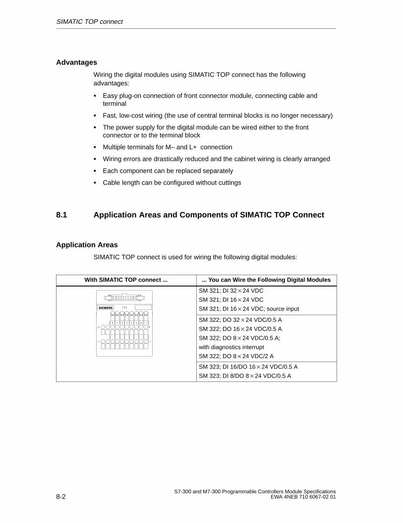
SIMATIC TOP connect
8-2S7-300 and M7-300 Programmable Controllers Module Specifications
EWA 4NEB 710 6067-02 01
Advantages
Wiring the digital modules using SIMATIC TOP connect has the followingadvantages:
Easy plug-on connection of front connector module, connecting cable andterminal
Fast, low-cost wiring (the use of central terminal blocks is no longer necessary)
The power supply for the digital module can be wired either to the frontconnector or to the terminal block
Multiple terminals for M– and L+ connection
Wiring errors are drastically reduced and the cabinet wiring is clearly arranged
Each component can be replaced separately
Cable length can be configured without cuttings
8.1 Application Areas and Components of SIMATIC TOP Connect
Application Areas
SIMATIC TOP connect is used for wiring the following digital modules:
With SIMATIC TOP connect ... ... You can W ire the Following Digital Modules
SM 321; DI 3224 VDC
SM 321; DI 1624 VDC
SM 321; DI 1624 VDC; source input
SM 322; DO 3224 VDC/0.5 A
SM 322; DO 1624 VDC/0.5 A
SM 322; DO 824 VDC/0.5 A;
with diagnostics interrupt
SM 322; DO 824 VDC/2 A
SM 323; DI 16/DO 1624 VDC/0.5 A
SM 323; DI 8/DO 824 VDC/0.5 A
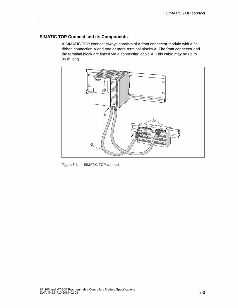
SIMATIC TOP connect
8-3S7-300 and M7-300 Programmable Controllers Module SpecificationsEWA 4NEB 710 6067-02 01
SIMATIC TOP Connect and its Components
A SIMATIC TOP connect always consists of a front connector module with a flatribbon connection À and one or more terminal blocks Â. The front connector andthe terminal block are linked via a connecting cable Á. This cable may be up to30 m long.
Â
Figure 8-1 SIMATIC TOP connect
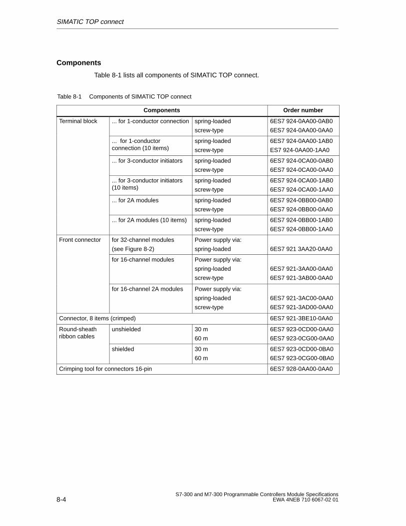
SIMATIC TOP connect
8-4S7-300 and M7-300 Programmable Controllers Module Specifications
EWA 4NEB 710 6067-02 01
Components
Table 8-1 lists all components of SIMATIC TOP connect.
Table 8-1 Components of SIMATIC TOP connect
Components Order number
Terminal block ... for 1-conductor connection spring-loaded
screw-type
6ES7 924-0AA00-0AB0
6ES7 924-0AA00-0AA0
... for 1-conductorconnection (10 items)
spring-loaded
screw-type
6ES7 924-0AA00-1AB0
ES7 924-0AA00-1AA0
... for 3-conductor initiators spring-loaded
screw-type
6ES7 924-0CA00-0AB0
6ES7 924-0CA00-0AA0
... for 3-conductor initiators(10 items)
spring-loaded
screw-type
6ES7 924-0CA00-1AB0
6ES7 924-0CA00-1AA0
... for 2A modules spring-loaded
screw-type
6ES7 924-0BB00-0AB0
6ES7 924-0BB00-0AA0
... for 2A modules (10 items) spring-loaded
screw-type
6ES7 924-0BB00-1AB0
6ES7 924-0BB00-1AA0
Front connector for 32-channel modules
(see Figure 8-2)
Power supply via:
spring-loaded 6ES7 921 3AA20-0AA0
for 16-channel modules Power supply via:
spring-loaded
screw-type
6ES7 921-3AA00-0AA0
6ES7 921-3AB00-0AA0
for 16-channel 2A modules Power supply via:
spring-loaded
screw-type
6ES7 921-3AC00-0AA0
6ES7 921-3AD00-0AA0
Connector, 8 items (crimped) 6ES7 921-3BE10-0AA0
Round-sheathribbon cables
unshielded 30 m
60 m
6ES7 923-0CD00-0AA0
6ES7 923-0CG00-0AA0
shielded 30 m
60 m
6ES7 923-0CD00-0BA0
6ES7 923-0CG00-0BA0
Crimping tool for connectors 16-pin 6ES7 928-0AA00-0AA0
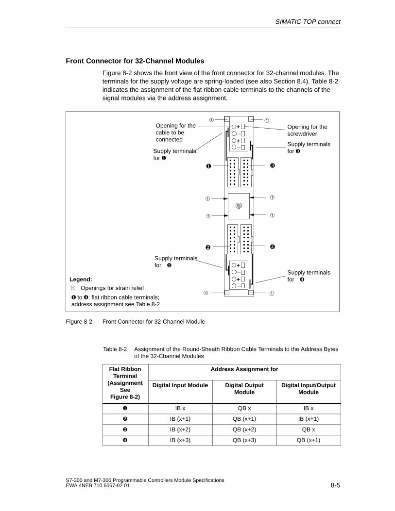
SIMATIC TOP connect
8-5S7-300 and M7-300 Programmable Controllers Module SpecificationsEWA 4NEB 710 6067-02 01
Front Connector for 32-Channel Modules
Figure 8-2 shows the front view of the front connector for 32-channel modules. Theterminals for the supply voltage are spring-loaded (see also Section 8.4). Table 8-2indicates the assignment of the flat ribbon cable terminals to the channels of thesignal modules via the address assignment.
+_
+_
+_
+_
Supply terminalsfor
Supply terminalsfor
Supply terminalsfor
Supply terminalsfor
Openings for strain relief
to : flat ribbon cable terminals;address assignment see Table 8-2
Opening for thescrewdriver
Opening for thecable to beconnected
Legend:
Figure 8-2 Front Connector for 32-Channel Module
Table 8-2 Assignment of the Round-Sheath Ribbon Cable Terminals to the Address Bytesof the 32-Channel Modules
Flat RibbonTerminal
(A i
Address Assignment forTerminal
(AssignmentSee
Figure 8-2)
Digital Input Module Digital OutputModule
Digital Input/OutputModule
IB x QB x IB x
IB (x+1) QB (x+1) IB (x+1)
IB (x+2) QB (x+2) QB x
IB (x+3) QB (x+3) QB (x+1)

SIMATIC TOP connect
8-6S7-300 and M7-300 Programmable Controllers Module Specifications
EWA 4NEB 710 6067-02 01
Selection Table
The following selection table shows to which SIMATIC TOP connect componentsthe digital modules can be wired. Please observe the Notes for Connection inSection 8.7.
Table 8-3 Selection Table for SIMATIC TOP Connect Components
Digital Modules Terminal Block Front Connectorg
for1-conductorconnection
for3-conductorconnection
for 2Amodules
for SM:16 or 32channels
for 2Amodules
SM 321; DI16 24 VDC X X X
SM 321; DI16 24 VDC;source input
X X X
SM 322; DO32 24 VDC/0.5 V X X – X –
SM 322; DO16 DC VDC/0.5 V X X X
SM 322; DO8 24 VDC/0.5 V;with diagnostics interrupt
X X X
SM 322; DO8 24 VDC/2 A X X
SM323;DI 16/DO1624 VDC/0.5 A
X X – X –
SM323;DI8/DO8 24VDC/0.5A
X X X
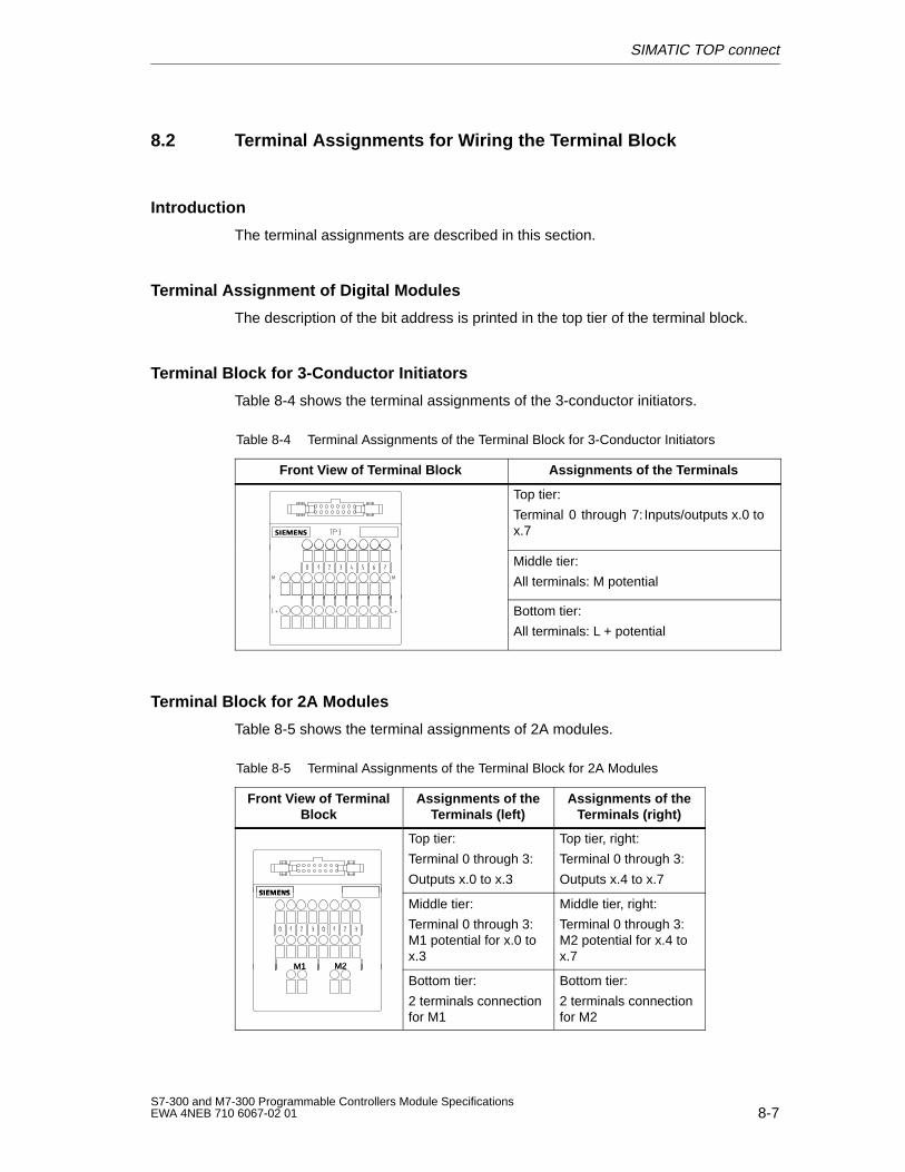
SIMATIC TOP connect
8-7S7-300 and M7-300 Programmable Controllers Module SpecificationsEWA 4NEB 710 6067-02 01
8.2 Terminal Assignments for Wiring the Terminal Block
Introduction
The terminal assignments are described in this section.
Terminal Assignment of Digital Modules
The description of the bit address is printed in the top tier of the terminal block.
Terminal Block for 3-Conductor Initiators
Table 8-4 shows the terminal assignments of the 3-conductor initiators.
Table 8-4 Terminal Assignments of the Terminal Block for 3-Conductor Initiators
Front V iew of T erminal Block Assignments of the T erminals
Top tier:
Terminal 0 through 7: Inputs/outputs x.0 tox.7
Middle tier:
All terminals: M potential
Bottom tier:
All terminals: L + potential
Terminal Block for 2A Modules
Table 8-5 shows the terminal assignments of 2A modules.
Table 8-5 Terminal Assignments of the Terminal Block for 2A Modules
Front V iew of T erminalBlock
Assignments of theTerminals (left)
Assignments of theTerminals (right)
Top tier:
Terminal 0 through 3:
Outputs x.0 to x.3
Top tier, right:
Terminal 0 through 3:
Outputs x.4 to x.7
M1 M2
Middle tier:
Terminal 0 through 3:M1 potential for x.0 tox.3
Middle tier, right:
Terminal 0 through 3:M2 potential for x.4 tox.7
M1 M2
Bottom tier:
2 terminals connectionfor M1
Bottom tier:
2 terminals connectionfor M2
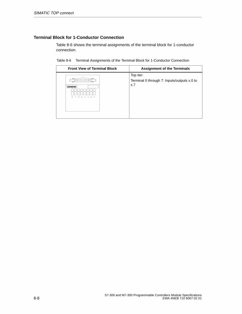
SIMATIC TOP connect
8-8S7-300 and M7-300 Programmable Controllers Module Specifications
EWA 4NEB 710 6067-02 01
Terminal Block for 1-Conductor Connection
Table 8-6 shows the terminal assignments of the terminal block for 1-conductorconnection.
Table 8-6 Terminal Assignments of the Terminal Block for 1-Conductor Connection
Front V iew of T erminal Block Assignment of the T erminals
Top tier:
Terminal 0 through 7: Inputs/outputs x.0 tox.7
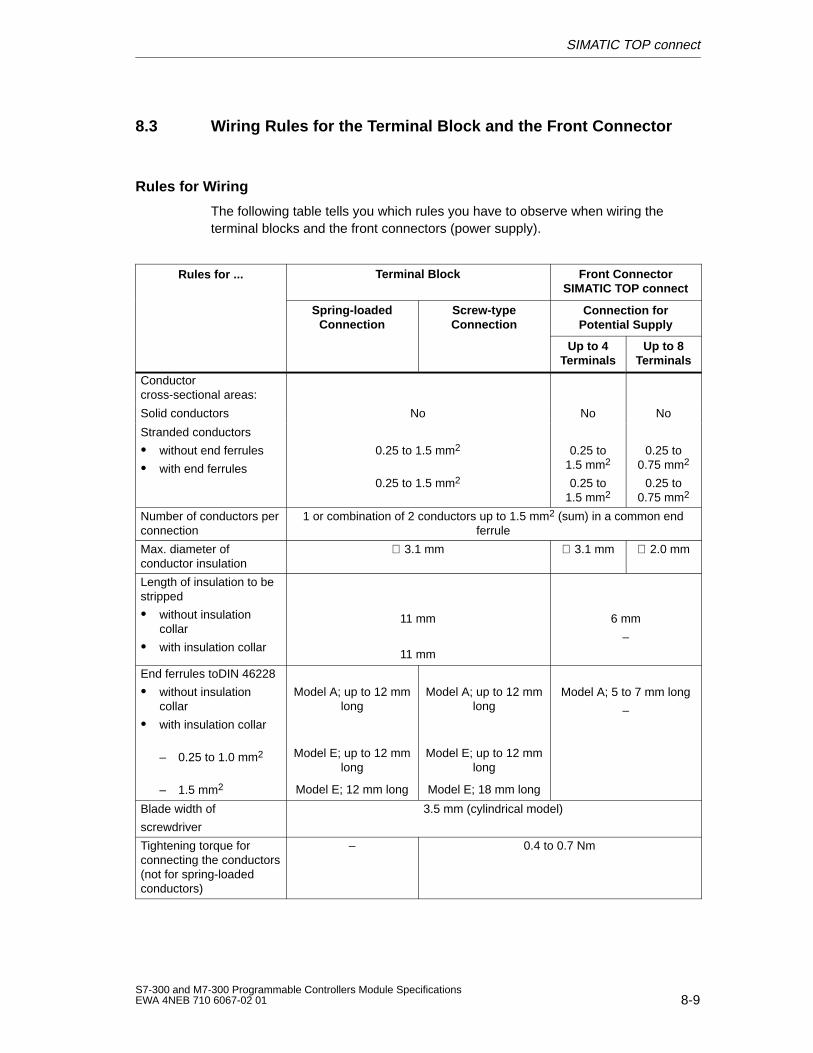
SIMATIC TOP connect
8-9S7-300 and M7-300 Programmable Controllers Module SpecificationsEWA 4NEB 710 6067-02 01
8.3 Wiring Rules for the Terminal Block and the Front Connector
Rules for Wiring
The following table tells you which rules you have to observe when wiring theterminal blocks and the front connectors (power supply).
Rules for ... Terminal Block Front ConnectorSIMATIC TOP connect
Spring-loadedConnection
Screw-typeConnection
Connection forPotential Supply
Up to 4Terminals
Up to 8Terminals
Conductorcross-sectional areas:
Solid conductors No No No
Stranded conductors
without end ferrules
with end ferrules
0.25 to 1.5 mm2
0.25 to 1.5 mm2
0.25 to1.5 mm2
0.25 to1.5 mm2
0.25 to0.75 mm2
0.25 to0.75 mm2
Number of conductors perconnection
1 or combination of 2 conductors up to 1.5 mm2 (sum) in a common endferrule
Max. diameter ofconductor insulation
∅ 3.1 mm ∅ 3.1 mm ∅ 2.0 mm
Length of insulation to bestripped
without insulationcollar
with insulation collar
11 mm
11 mm
6 mm
–
End ferrules toDIN 46228
without insulationcollar
with insulation collar
– 0.25 to 1.0 mm2
– 1.5 mm2
Model A; up to 12 mmlong
Model E; up to 12 mmlong
Model E; 12 mm long
Model A; up to 12 mmlong
Model E; up to 12 mmlong
Model E; 18 mm long
Model A; 5 to 7 mm long
–
Blade width of
screwdriver
3.5 mm (cylindrical model)
Tightening torque forconnecting the conductors(not for spring-loadedconductors)
– 0.4 to 0.7 Nm
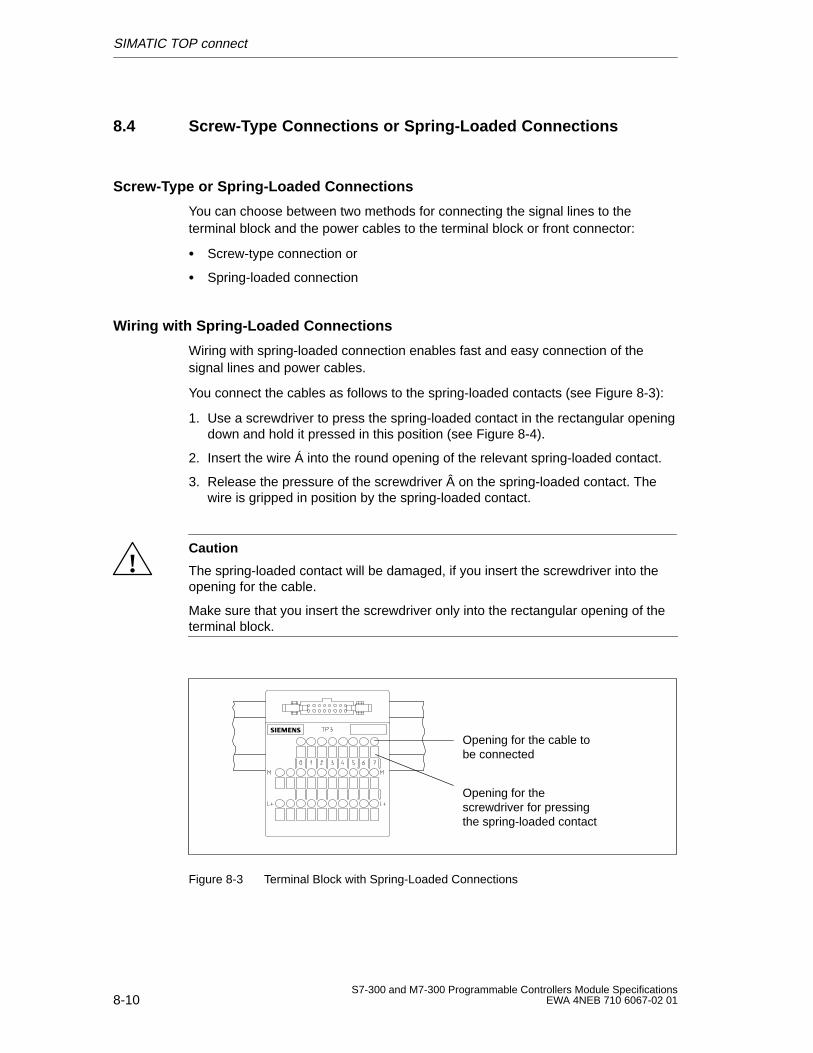
SIMATIC TOP connect
8-10S7-300 and M7-300 Programmable Controllers Module Specifications
EWA 4NEB 710 6067-02 01
8.4 Screw-Type Connections or Spring-Loaded Connections
Screw-Type or Spring-Loaded Connections
You can choose between two methods for connecting the signal lines to theterminal block and the power cables to the terminal block or front connector:
Screw-type connection or
Spring-loaded connection
Wiring with Spring-Loaded Connections
Wiring with spring-loaded connection enables fast and easy connection of thesignal lines and power cables.
You connect the cables as follows to the spring-loaded contacts (see Figure 8-3):
1. Use a screwdriver to press the spring-loaded contact in the rectangular openingdown and hold it pressed in this position (see Figure 8-4).
2. Insert the wire Á into the round opening of the relevant spring-loaded contact.
3. Release the pressure of the screwdriver  on the spring-loaded contact. Thewire is gripped in position by the spring-loaded contact.
!Caution
The spring-loaded contact will be damaged, if you insert the screwdriver into theopening for the cable.
Make sure that you insert the screwdriver only into the rectangular opening of theterminal block.
Opening for thescrewdriver for pressingthe spring-loaded contact
Opening for the cable tobe connected
Figure 8-3 Terminal Block with Spring-Loaded Connections
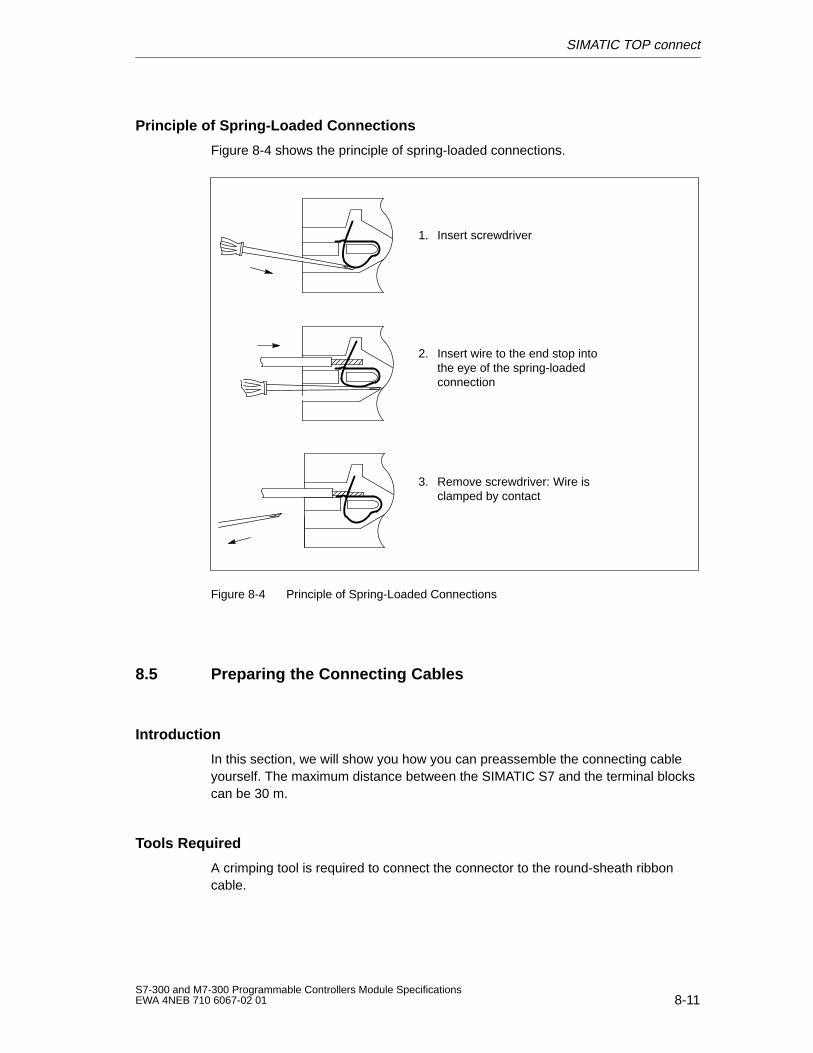
SIMATIC TOP connect
8-11S7-300 and M7-300 Programmable Controllers Module SpecificationsEWA 4NEB 710 6067-02 01
Principle of Spring-Loaded Connections
Figure 8-4 shows the principle of spring-loaded connections.
1. Insert screwdriver
2. Insert wire to the end stop intothe eye of the spring-loadedconnection
3. Remove screwdriver: Wire isclamped by contact
Figure 8-4 Principle of Spring-Loaded Connections
8.5 Preparing the Connecting Cables
Introduction
In this section, we will show you how you can preassemble the connecting cableyourself. The maximum distance between the SIMATIC S7 and the terminal blockscan be 30 m.
Tools Required
A crimping tool is required to connect the connector to the round-sheath ribboncable.
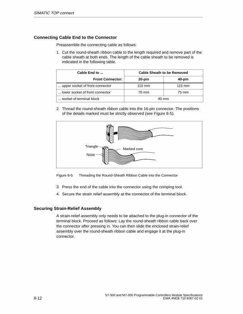
SIMATIC TOP connect
8-12S7-300 and M7-300 Programmable Controllers Module Specifications
EWA 4NEB 710 6067-02 01
Connecting Cable End to the Connector
Preassemble the connecting cable as follows:
1. Cut the round-sheath ribbon cable to the length required and remove part of thecable sheath at both ends. The length of the cable sheath to be removed isindicated in the following table.
Cable End to ... Cable Sheath to be Removed
Front Connector: 20-pin 40-pin
... upper socket of front connector 110 mm 115 mm
... lower socket of front connector 70 mm 75 mm
... socket of terminal block 40 mm
2. Thread the round-sheath ribbon cable into the 16-pin connector. The positionsof the details marked must be strictly observed (see Figure 8-5).
Triangle
Nose
Marked core
Figure 8-5 Threading the Round-Sheath Ribbon Cable into the Connector
3. Press the end of the cable into the connector using the crimping tool.
4. Secure the strain relief assembly at the connector of the terminal block.
Securing Strain-Relief Assembly
A strain-relief assembly only needs to be attached to the plug-in connector of theterminal block. Proceed as follows: Lay the round-sheath ribbon cable back overthe connector after pressing in. You can then slide the enclosed strain-reliefassembly over the round-sheath ribbon cable and engage it at the plug-inconnector.
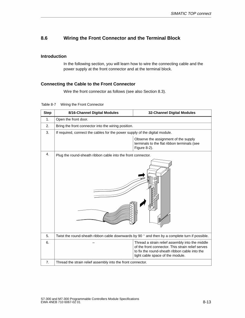
SIMATIC TOP connect
8-13S7-300 and M7-300 Programmable Controllers Module SpecificationsEWA 4NEB 710 6067-02 01
8.6 Wiring the Front Connector and the Terminal Block
Introduction
In the following section, you will learn how to wire the connecting cable and thepower supply at the front connector and at the terminal block.
Connecting the Cable to the Front Connector
Wire the front connector as follows (see also Section 8.3).
Table 8-7 Wiring the Front Connector
Step 8/16-Channel Digital Modules 32-Channel Digital Modules
1. Open the front door.
2. Bring the front connector into the wiring position.
3. If required, connect the cables for the power supply of the digital module.
Observe the assignment of the supplyterminals to the flat ribbon terminals (seeFigure 8-2).
4. Plug the round-sheath ribbon cable into the front connector.
5. Twist the round-sheath ribbon cable downwards by 90 and then by a complete turn if possible.
6. – Thread a strain relief assembly into the middleof the front connector. This strain relief servesto fix the round-sheath ribbon cable into thetight cable space of the module.
7. Thread the strain relief assembly into the front connector.
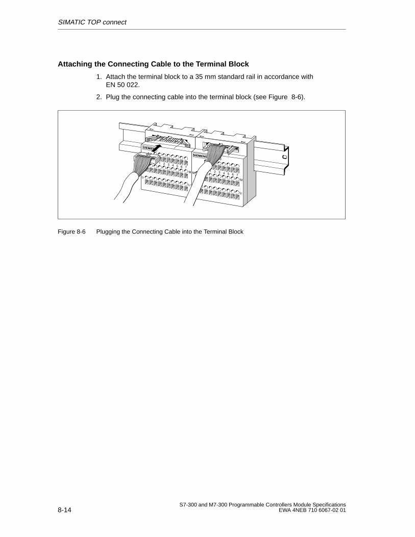
SIMATIC TOP connect
8-14S7-300 and M7-300 Programmable Controllers Module Specifications
EWA 4NEB 710 6067-02 01
Attaching the Connecting Cable to the Terminal Block
1. Attach the terminal block to a 35 mm standard rail in accordance with EN 50 022.
2. Plug the connecting cable into the terminal block (see Figure 8-6).
Figure 8-6 Plugging the Connecting Cable into the Terminal Block
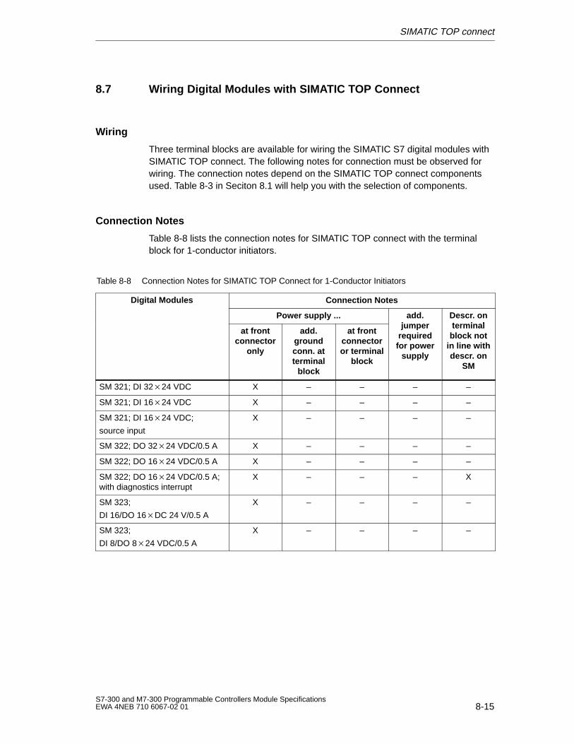
SIMATIC TOP connect
8-15S7-300 and M7-300 Programmable Controllers Module SpecificationsEWA 4NEB 710 6067-02 01
8.7 Wiring Digital Modules with SIMATIC TOP Connect
Wiring
Three terminal blocks are available for wiring the SIMATIC S7 digital modules withSIMATIC TOP connect. The following notes for connection must be observed forwiring. The connection notes depend on the SIMATIC TOP connect componentsused. Table 8-3 in Seciton 8.1 will help you with the selection of components.
Connection Notes
Table 8-8 lists the connection notes for SIMATIC TOP connect with the terminalblock for 1-conductor initiators.
Table 8-8 Connection Notes for SIMATIC TOP Connect for 1-Conductor Initiators
Digital Modules Connection Notesg
Power supply ... add.jumper
Descr . onterminal
at frontconnector
only
add.groundconn. atterminal
block
at frontconnectoror terminal
block
jumperrequiredfor power
supply
terminalblock not
in line withdescr . on
SM
SM 321; DI 3224 VDC X – – – –
SM 321; DI 1624 VDC X – – – –
SM 321; DI 1624 VDC;
source input
X – – – –
SM 322; DO 3224 VDC/0.5 A X – – – –
SM 322; DO 1624 VDC/0.5 A X – – – –
SM 322; DO 1624 VDC/0.5 A;with diagnostics interrupt
X – – – X
SM 323;
DI 16/DO 16DC 24 V/0.5 A
X – – – –
SM 323;
DI 8/DO 824 VDC/0.5 A
X – – – –
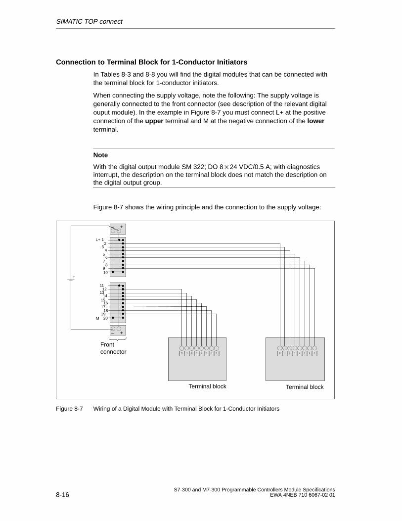
SIMATIC TOP connect
8-16S7-300 and M7-300 Programmable Controllers Module Specifications
EWA 4NEB 710 6067-02 01
Connection to Terminal Block for 1-Conductor Initiators
In Tables 8-3 and 8-8 you will find the digital modules that can be connected withthe terminal block for 1-conductor initiators.
When connecting the supply voltage, note the following: The supply voltage isgenerally connected to the front connector (see description of the relevant digitalouput module). In the example in Figure 8-7 you must connect L+ at the positiveconnection of the upper terminal and M at the negative connection of the lowerterminal.
Note
With the digital output module SM 322; DO 824 VDC/0.5 A; with diagnosticsinterrupt, the description on the terminal block does not match the description onthe digital output group.
Figure 8-7 shows the wiring principle and the connection to the supply voltage:
12
34
56
78
910
Frontconnector
– +
1112
1314
1516
1718
1920
L+
M
– +
Terminal block Terminal block
Figure 8-7 Wiring of a Digital Module with Terminal Block for 1-Conductor Initiators
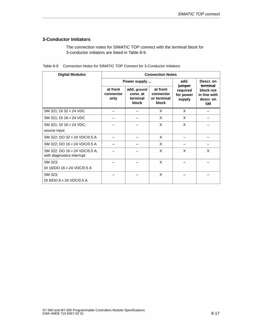
SIMATIC TOP connect
8-17S7-300 and M7-300 Programmable Controllers Module SpecificationsEWA 4NEB 710 6067-02 01
3-Conductor Initiators
The connection notes for SIMATIC TOP connect with the terminal block for3-conductor initiators are listed in Table 8-9.
Table 8-9 Connection Notes for SIMATIC TOP Connect for 3-Conductor Initiators
Digital Modules Connection Notesg
Power supply ... add.jumper
Descr . onterminal
at frontconnector
only
add. groundconn. atterminal
block
at frontconnectoror terminal
block
jumperrequiredfor power
supply
terminalblock not
in line withdescr . on
SM
SM 321; DI 3224 VDC – – X X –
SM 321; DI 1624 VDC – – X X –
SM 321; DI 1624 VDC;
source input
– – X X –
SM 322; DO 3224 VDC/0.5 A – – X – –
SM 322; DO 1624 VDC/0.5 A – – X – –
SM 322; DO 1624 VDC/0.5 A;with diagnostics interrupt
– – X X X
SM 323;
DI 16/DO 1624 VDC/0.5 A
– – X – –
SM 323;
DI 8/DO 824 VDC/0.5 A
– – X – –
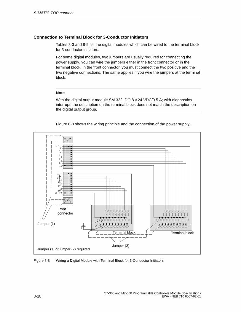
SIMATIC TOP connect
8-18S7-300 and M7-300 Programmable Controllers Module Specifications
EWA 4NEB 710 6067-02 01
Connection to Terminal Block for 3-Conductor Initiators
Tables 8-3 and 8-9 list the digital modules which can be wired to the terminal blockfor 3-conductor initiators.
For some digital modules, two jumpers are usually required for connecting thepower supply. You can wire the jumpers either in the front connector or in theterminal block. In the front connector, you must connect the two positive and thetwo negative connections. The same applies if you wire the jumpers at the terminalblock.
Note
With the digital output module SM 322; DO 824 VDC/0.5 A; with diagnosticsinterrupt, the description on the terminal block does not match the description onthe digital output group.
Figure 8-8 shows the wiring principle and the connection of the power supply.
12
34
56
78
910
Frontconnector
Terminal block
– +
1112
1314
1516
1718
1920
L+
M
– +
Terminal block
Jumper (2)
Jumper (1)
Jumper (1) or jumper (2) required
Figure 8-8 Wiring a Digital Module with Terminal Block for 3-Conductor Initiators
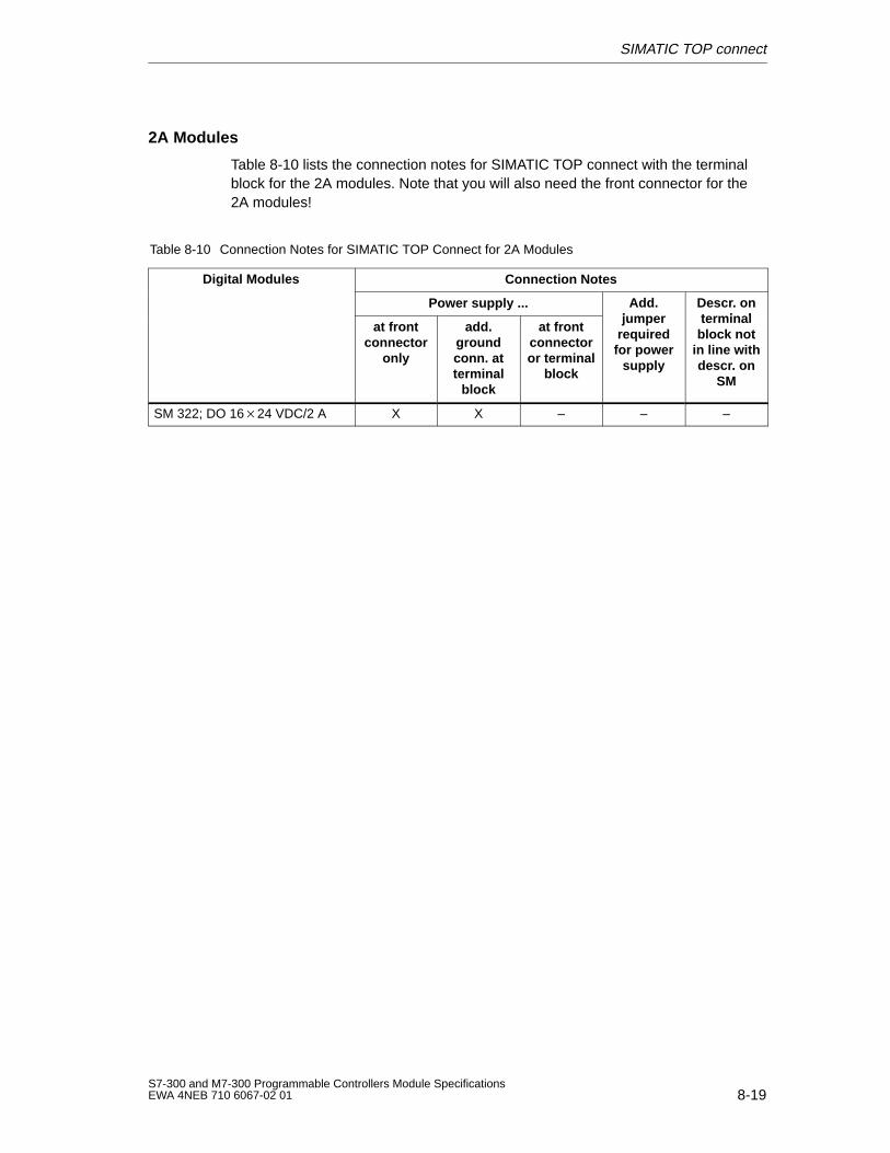
SIMATIC TOP connect
8-19S7-300 and M7-300 Programmable Controllers Module SpecificationsEWA 4NEB 710 6067-02 01
2A Modules
Table 8-10 lists the connection notes for SIMATIC TOP connect with the terminalblock for the 2A modules. Note that you will also need the front connector for the2A modules!
Table 8-10 Connection Notes for SIMATIC TOP Connect for 2A Modules
Digital Modules Connection Notesg
Power supply ... Add.jumper
Descr . onterminal
at frontconnector
only
add.groundconn. atterminal
block
at frontconnectoror terminal
block
jumperrequiredfor power
supply
terminalblock not
in line withdescr . on
SM
SM 322; DO 1624 VDC/2 A X X – – –
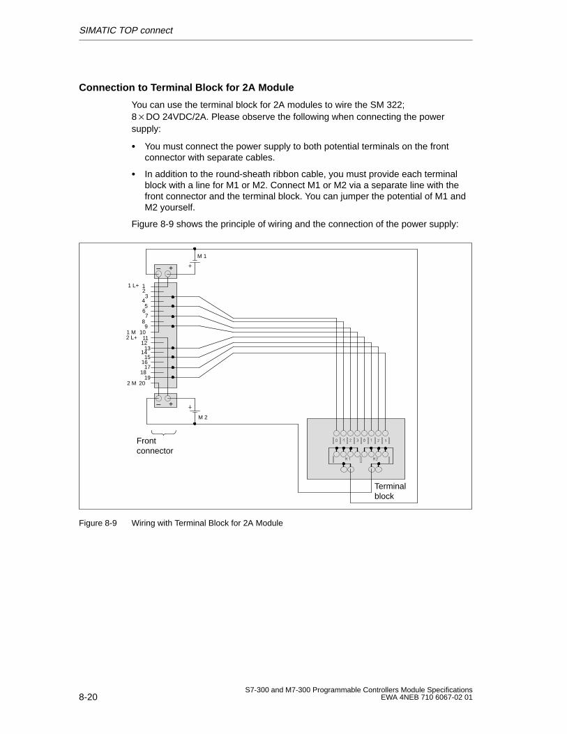
SIMATIC TOP connect
8-20S7-300 and M7-300 Programmable Controllers Module Specifications
EWA 4NEB 710 6067-02 01
Connection to Terminal Block for 2A Module
You can use the terminal block for 2A modules to wire the SM 322;8DO 24VDC/2A. Please observe the following when connecting the powersupply:
You must connect the power supply to both potential terminals on the frontconnector with separate cables.
In addition to the round-sheath ribbon cable, you must provide each terminalblock with a line for M1 or M2. Connect M1 or M2 via a separate line with thefront connector and the terminal block. You can jumper the potential of M1 andM2 yourself.
Figure 8-9 shows the principle of wiring and the connection of the power supply:
Frontconnector
– +
1112
1314
151617
1819
20
1 L+
2 M
– +
123
45
67
89
101 M2 L+
Terminalblock
M 1
M 2
Figure 8-9 Wiring with Terminal Block for 2A Module
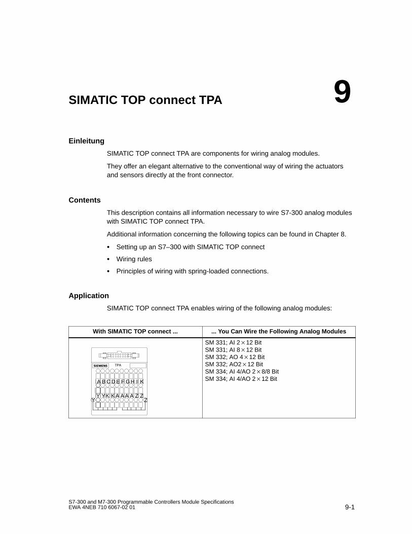
9-1S7-300 and M7-300 Programmable Controllers Module SpecificationsEWA 4NEB 710 6067-02 01
SIMATIC TOP connect TPA
Einleitung
SIMATIC TOP connect TPA are components for wiring analog modules.
They offer an elegant alternative to the conventional way of wiring the actuatorsand sensors directly at the front connector.
Contents
This description contains all information necessary to wire S7-300 analog moduleswith SIMATIC TOP connect TPA.
Additional information concerning the following topics can be found in Chapter 8.
Setting up an S7–300 with SIMATIC TOP connect
Wiring rules
Principles of wiring with spring-loaded connections.
Application
SIMATIC TOP connect TPA enables wiring of the following analog modules:
With SIMATIC TOP connect ... ... You Can W ire the Following Analog Modules
A B C D E F GH I K
Y YK K A A A A Z ZY Z
SM 331; AI 212 BitSM 331; AI 812 BitSM 332; AO 412 BitSM 332; AO212 BitSM 334; AI 4/AO 28/8 BitSM 334; AI 4/AO 212 Bit
9
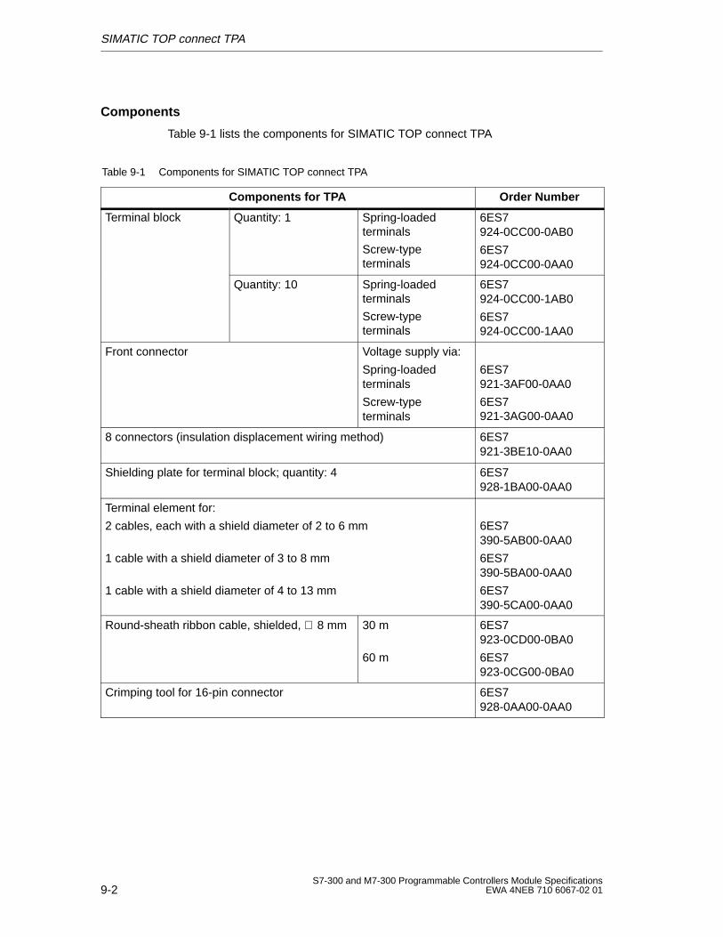
SIMATIC TOP connect TPA
9-2S7-300 and M7-300 Programmable Controllers Module Specifications
EWA 4NEB 710 6067-02 01
Components
Table 9-1 lists the components for SIMATIC TOP connect TPA
Table 9-1 Components for SIMATIC TOP connect TPA
Components for TPA Order Number
Terminal block Quantity: 1 Spring-loadedterminals
Screw-typeterminals
6ES7924-0CC00-0AB0
6ES7924-0CC00-0AA0
Quantity: 10 Spring-loadedterminals
Screw-typeterminals
6ES7924-0CC00-1AB0
6ES7924-0CC00-1AA0
Front connector Voltage supply via:
Spring-loadedterminals
Screw-typeterminals
6ES7921-3AF00-0AA0
6ES7921-3AG00-0AA0
8 connectors (insulation displacement wiring method) 6ES7921-3BE10-0AA0
Shielding plate for terminal block; quantity: 4 6ES7928-1BA00-0AA0
Terminal element for:
2 cables, each with a shield diameter of 2 to 6 mm
1 cable with a shield diameter of 3 to 8 mm
1 cable with a shield diameter of 4 to 13 mm
6ES7390-5AB00-0AA0
6ES7390-5BA00-0AA0
6ES7390-5CA00-0AA0
Round-sheath ribbon cable, shielded, ∅ 8 mm 30 m
60 m
6ES7923-0CD00-0BA0
6ES7923-0CG00-0BA0
Crimping tool for 16-pin connector 6ES7928-0AA00-0AA0
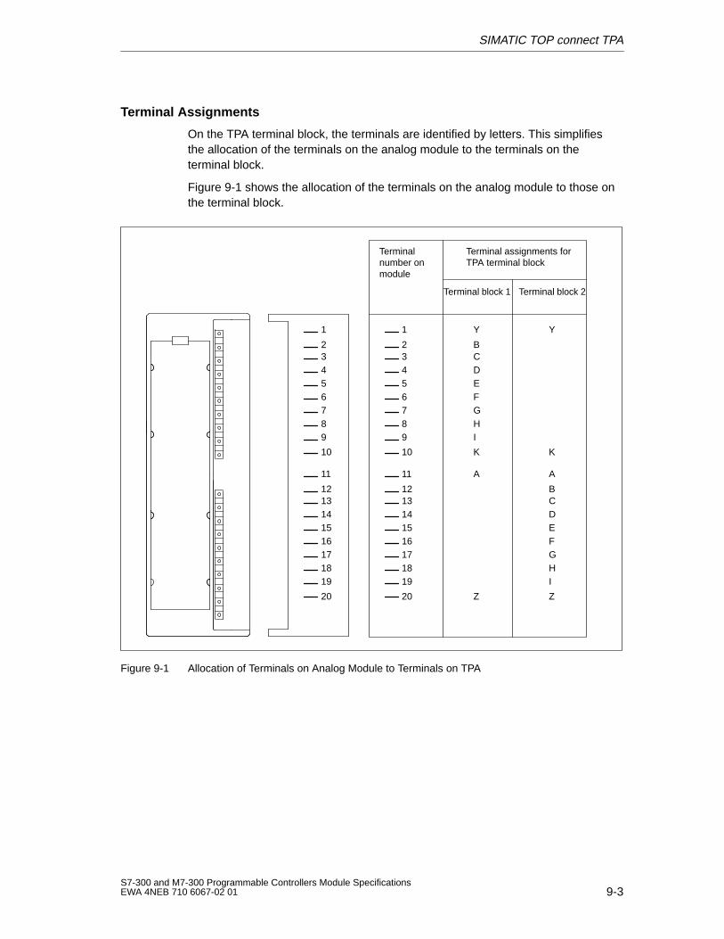
SIMATIC TOP connect TPA
9-3S7-300 and M7-300 Programmable Controllers Module SpecificationsEWA 4NEB 710 6067-02 01
Terminal Assignments
On the TPA terminal block, the terminals are identified by letters. This simplifiesthe allocation of the terminals on the analog module to the terminals on theterminal block.
Figure 9-1 shows the allocation of the terminals on the analog module to those onthe terminal block.
Terminalnumber onmodule
Terminal assignments forTPA terminal block
Terminal block 1 Terminal block 2
12
11
13141516171819
20
Y
BCDEFGHI
K
A
Z
Y
K
B
A
CDEFGHI
Z
12
11
13141516171819
20
2
1
3456789
10
2
1
3456789
10
Figure 9-1 Allocation of Terminals on Analog Module to Terminals on TPA
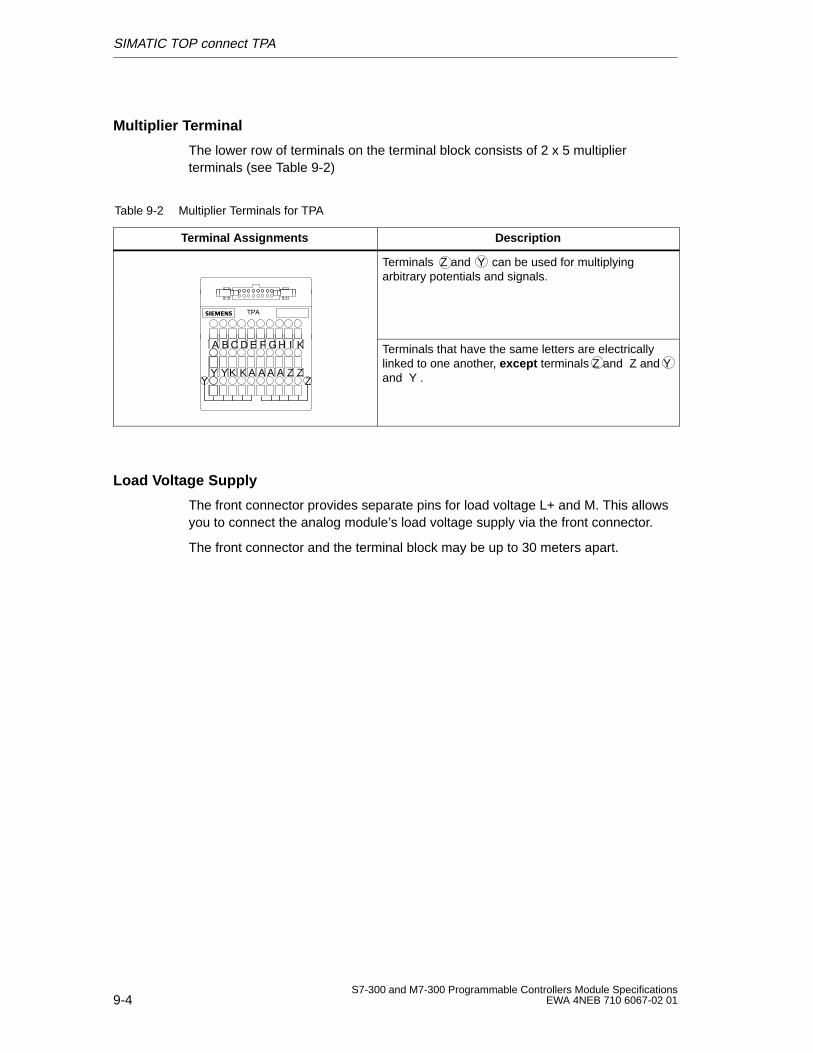
SIMATIC TOP connect TPA
9-4S7-300 and M7-300 Programmable Controllers Module Specifications
EWA 4NEB 710 6067-02 01
Multiplier Terminal
The lower row of terminals on the terminal block consists of 2 x 5 multiplierterminals (see Table 9-2)
Table 9-2 Multiplier Terminals for TPA
Terminal Assignments Description
Terminals Z and Y can be used for multiplyingarbitrary potentials and signals.
A B C D E F GH I K
Y YK K A A A A Z ZY Z
Terminals that have the same letters are electricallylinked to one another, except terminals Z and Z and Yand Y .
Load Voltage Supply
The front connector provides separate pins for load voltage L+ and M. This allowsyou to connect the analog module’s load voltage supply via the front connector.
The front connector and the terminal block may be up to 30 meters apart.
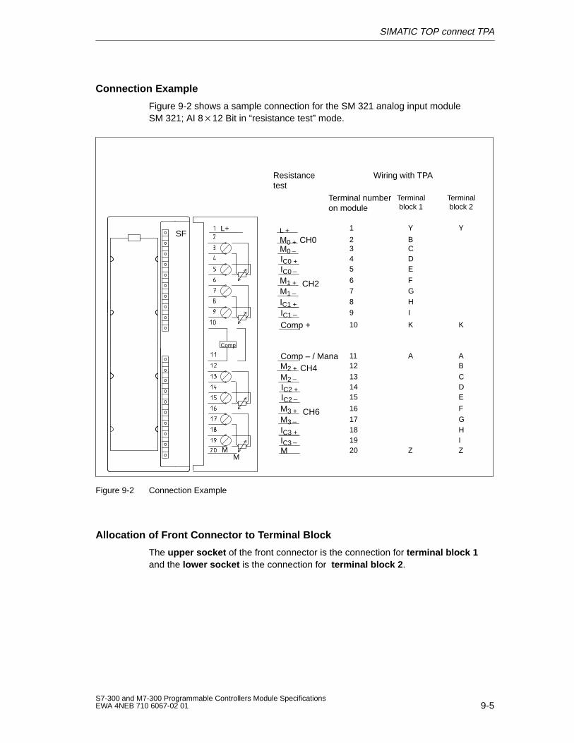
SIMATIC TOP connect TPA
9-5S7-300 and M7-300 Programmable Controllers Module SpecificationsEWA 4NEB 710 6067-02 01
Connection Example
Figure 9-2 shows a sample connection for the SM 321 analog input moduleSM 321; AI 812 Bit in “resistance test” mode.
Comp – / Mana
Resistancetest
Comp +
SF
M
L+
M0 + CH0M0IC0 +IC0M1 + CH2M1IC1 +IC1
M2 + CH4M2IC2 +IC2
M3 + CH6M3IC3 +IC3
Comp
M
L +
M
Wiring with TPA
Terminalblock 1
Terminalblock 2
1211
131415
16
17181920
Y
BCDE
FG
HI
K
A
Z
Y
K
BA
CDE
F
GHIZ
2
1
345
67
89
10
Terminal numberon module
Figure 9-2 Connection Example
Allocation of Front Connector to Terminal Block
The upper socket of the front connector is the connection for terminal block 1and the lower socket is the connection for terminal block 2 .
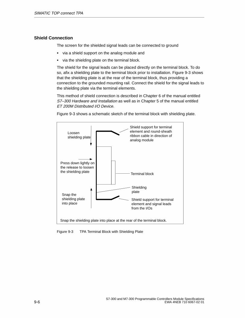
SIMATIC TOP connect TPA
9-6S7-300 and M7-300 Programmable Controllers Module Specifications
EWA 4NEB 710 6067-02 01
Shield Connection
The screen for the shielded signal leads can be connected to ground
via a shield support on the analog module and
via the shielding plate on the terminal block.
The shield for the signal leads can be placed directly on the terminal block. To doso, afix a shielding plate to the terminal block prior to installation. Figure 9-3 showsthat the shielding plate is at the rear of the terminal block, thus providing aconnection to the grounded mounting rail. Connect the shield for the signal leads tothe shielding plate via the terminal elements.
This method of shield connection is described in Chapter 6 of the manual entitledS7–300 Hardware and Installation as well as in Chapter 5 of the manual entitledET 200M Distributed I/O Device.
Figure 9-3 shows a schematic sketch of the terminal block with shielding plate.
Shield support for terminalelement and round-sheathribbon cable in direction ofanalog module
Terminal block
Shield support for terminalelement and signal leadsfrom the I/Os
Shieldingplate
Snap the shielding plate into place at the rear of the terminal block.
Loosenshielding plate
Snap theshielding plateinto place
Press down lightly onthe release to loosenthe shielding plate
Figure 9-3 TPA Terminal Block with Shielding Plate
A-1S7-300 and M7-300 Programmable Controllers Module SpecificationsEWA 4NEB 710 6067-02 01
Parameter Sets for Signal Modules
In this Appendix
This appendix briefly describes how to assign the parameters for signal modules inthe STEP 7 user program. You can assign the parameters for the signal modulesin the user program instead of, or as well as, with the proogramming device inSTEP 7.
This appendix also contains the structure of the parameters for the various classesof signal modules.
Reference Literature
In the System and Standard Functions Reference Manual, you will find acomprehensive description of how to assign the parameters for signal modules inthe user program, as well as a description of the SFCs used.
In M7-300:
You can also use the M7-API to assign the parameters in the user program forM7-300 CPUs or FMs (see the Manuals for M7-300/400 System Software).
Contents
This appendix contains the parameter sets for the following classes of signalmodules on the S7-300:
Section Contents Page
A.1 How to Assign the Parameters for Signal Modules in the UserProgram
A-2
A.2 Parameters of the Digital Input Modules A-3
A.3 Parameters of the Digital Output Modules A-5
A.4 Parameters of the Analog Input Modules A-7
A.5 Parameters of the Analog Output Modules A-11
A
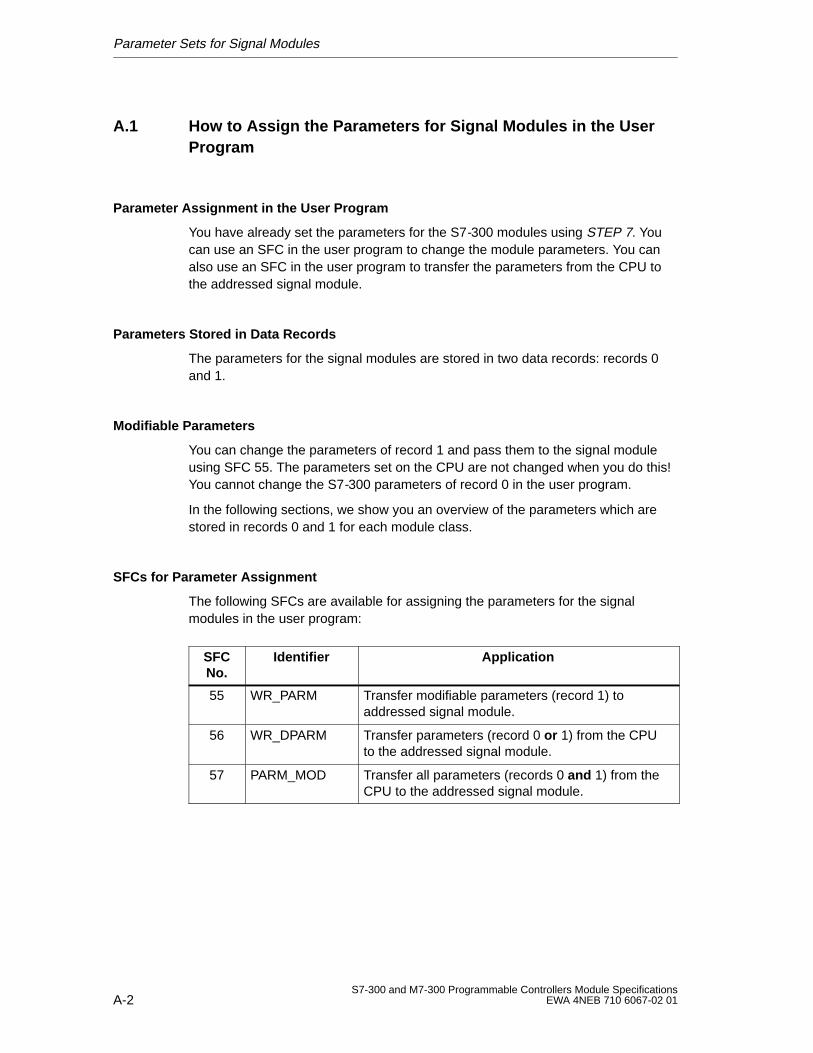
Parameter Sets for Signal Modules
A-2S7-300 and M7-300 Programmable Controllers Module Specifications
EWA 4NEB 710 6067-02 01
A.1 How to Assign the Parameters for Signal Modules in the UserProgram
Parameter Assignment in the User Program
You have already set the parameters for the S7-300 modules using STEP 7. Youcan use an SFC in the user program to change the module parameters. You canalso use an SFC in the user program to transfer the parameters from the CPU tothe addressed signal module.
Parameters Stored in Data Records
The parameters for the signal modules are stored in two data records: records 0and 1.
Modifiable Parameters
You can change the parameters of record 1 and pass them to the signal moduleusing SFC 55. The parameters set on the CPU are not changed when you do this!You cannot change the S7-300 parameters of record 0 in the user program.
In the following sections, we show you an overview of the parameters which arestored in records 0 and 1 for each module class.
SFCs for Parameter Assignment
The following SFCs are available for assigning the parameters for the signalmodules in the user program:
SFCNo.
Identifier Application
55 WR_PARM Transfer modifiable parameters (record 1) toaddressed signal module.
56 WR_DPARM Transfer parameters (record 0 or 1) from the CPUto the addressed signal module.
57 PARM_MOD Transfer all parameters (records 0 and 1) from theCPU to the addressed signal module.
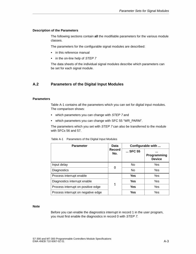
Parameter Sets for Signal Modules
A-3S7-300 and M7-300 Programmable Controllers Module SpecificationsEWA 4NEB 710 6067-02 01
Description of the Parameters
The following sections contain all the modifiable parameters for the various moduleclasses.
The parameters for the configurable signal modules are described:
in this reference manual
in the on-line help of STEP 7
The data sheets of the individual signal modules describe which parameters canbe set for each signal module.
A.2 Parameters of the Digital Input Modules
Parameters
Table A-1 contains all the parameters which you can set for digital input modules.The comparison shows:
which parameters you can change with STEP 7 and
which parameters you can change with SFC 55 “WR_PARM”.
The parameters which you set with STEP 7 can also be transferred to the modulewith SFCs 56 and 57.
Table A-1 Parameters of the Digital Input Modules
Parameter DataRecord
Configurable with ...Record
No.... SFC 55 ...
ProgrammingDevice
Input delay0
No Yes
Diagnostics0
No Yes
Process interrupt enable Yes Yes
Diagnostics interrupt enable1
Yes Yes
Process interrupt on positive edge1
Yes Yes
Process interrupt on negative edge Yes Yes
Note
Before you can enable the diagnostics interrupt in record 1 in the user program,you must first enable the diagnostics in record 0 with STEP 7.
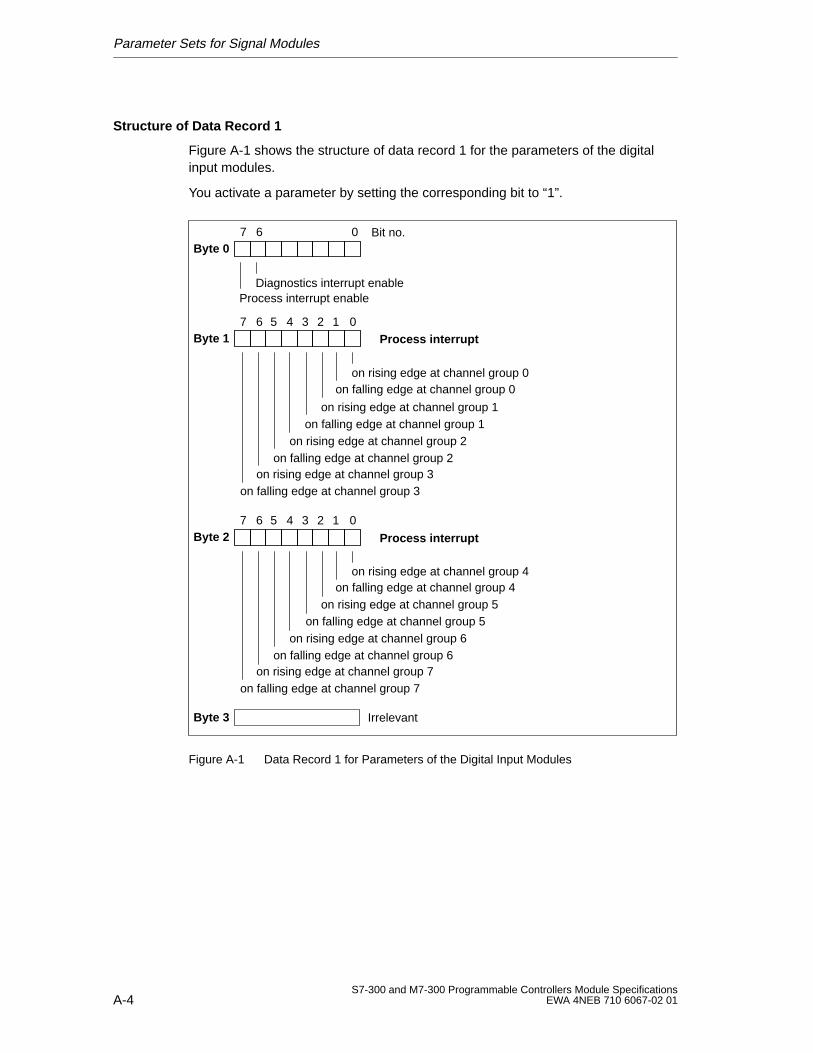
Parameter Sets for Signal Modules
A-4S7-300 and M7-300 Programmable Controllers Module Specifications
EWA 4NEB 710 6067-02 01
Structure of Data Record 1
Figure A-1 shows the structure of data record 1 for the parameters of the digitalinput modules.
You activate a parameter by setting the corresponding bit to “1”.
Byte 07 6 0 Bit no.
Process interrupt enableDiagnostics interrupt enable
Byte 17 6 0
on rising edge at channel group 0on falling edge at channel group 0
on rising edge at channel group 1on falling edge at channel group 1
on rising edge at channel group 2on falling edge at channel group 2
on rising edge at channel group 3on falling edge at channel group 3
5 4 3 2 1
Byte 27 6 0
on rising edge at channel group 4on falling edge at channel group 4
on rising edge at channel group 5 on falling edge at channel group 5
on rising edge at channel group 6on falling edge at channel group 6
on rising edge at channel group 7on falling edge at channel group 7
5 4 3 2 1
Byte 3 Irrelevant
Process interrupt
Process interrupt
Figure A-1 Data Record 1 for Parameters of the Digital Input Modules
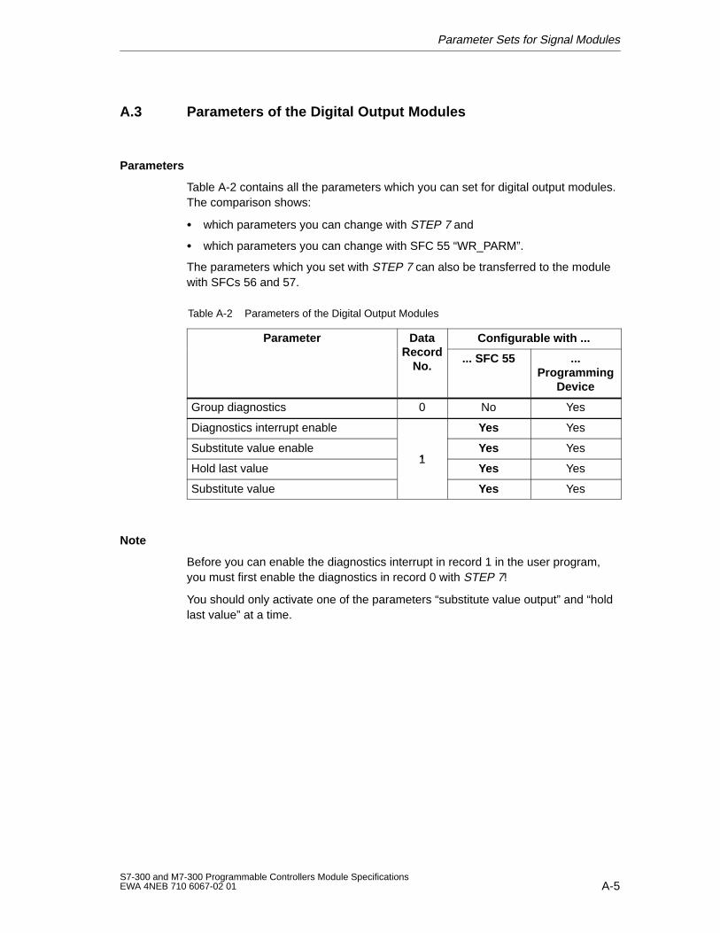
Parameter Sets for Signal Modules
A-5S7-300 and M7-300 Programmable Controllers Module SpecificationsEWA 4NEB 710 6067-02 01
A.3 Parameters of the Digital Output Modules
Parameters
Table A-2 contains all the parameters which you can set for digital output modules.The comparison shows:
which parameters you can change with STEP 7 and
which parameters you can change with SFC 55 “WR_PARM”.
The parameters which you set with STEP 7 can also be transferred to the modulewith SFCs 56 and 57.
Table A-2 Parameters of the Digital Output Modules
Parameter DataRecord
Configurable with ...Record
No.... SFC 55 ...
ProgrammingDevice
Group diagnostics 0 No Yes
Diagnostics interrupt enable Yes Yes
Substitute value enable1
Yes Yes
Hold last value1
Yes Yes
Substitute value Yes Yes
Note
Before you can enable the diagnostics interrupt in record 1 in the user program,you must first enable the diagnostics in record 0 with STEP 7!
You should only activate one of the parameters “substitute value output” and “holdlast value” at a time.
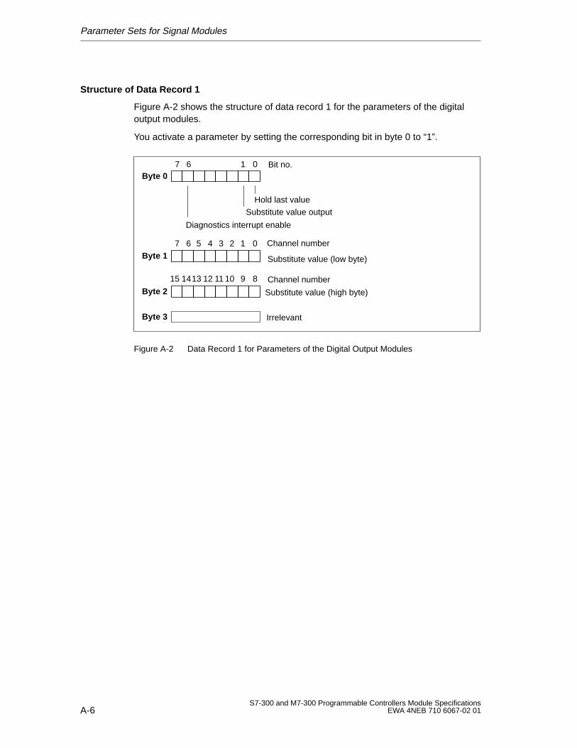
Parameter Sets for Signal Modules
A-6S7-300 and M7-300 Programmable Controllers Module Specifications
EWA 4NEB 710 6067-02 01
Structure of Data Record 1
Figure A-2 shows the structure of data record 1 for the parameters of the digitaloutput modules.
You activate a parameter by setting the corresponding bit in byte 0 to “1”.
Byte 07 6 0 Bit no.1
Hold last value
Byte 1
Byte 2
Byte 3 Irrelevant
7 6 05 4 3 2 1
15 14 813 12 11 10 9
Channel number
Substitute value output
Diagnostics interrupt enable
Substitute value (low byte)
Channel number
Substitute value (high byte)
Figure A-2 Data Record 1 for Parameters of the Digital Output Modules
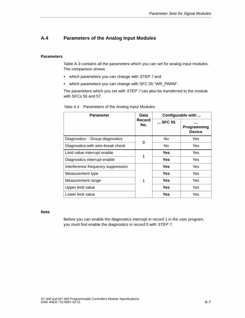
Parameter Sets for Signal Modules
A-7S7-300 and M7-300 Programmable Controllers Module SpecificationsEWA 4NEB 710 6067-02 01
A.4 Parameters of the Analog Input Modules
Parameters
Table A-3 contains all the parameters which you can set for analog input modules.The comparison shows:
which parameters you can change with STEP 7 and
which parameters you can change with SFC 55 “WR_PARM”.
The parameters which you set with STEP 7 can also be transferred to the modulewith SFCs 56 and 57.
Table A-3 Parameters of the Analog Input Modules
Parameter DataRecord
Configurable with ...Record
No.... SFC 55 ...
ProgrammingDevice
Diagnostics: : Group diagnostics0
No Yes
Diagnostics:with wire-break check0
No Yes
Limit value interrupt enable1
Yes Yes
Diagnostics interrupt enable1
Yes Yes
Interference frequency suppression Yes Yes
Measurement type Yes Yes
Measurement range 1 Yes Yes
Upper limit value Yes Yes
Lower limit value Yes Yes
Note
Before you can enable the diagnostics interrupt in record 1 in the user program,you must first enable the diagnostics in record 0 with STEP 7.
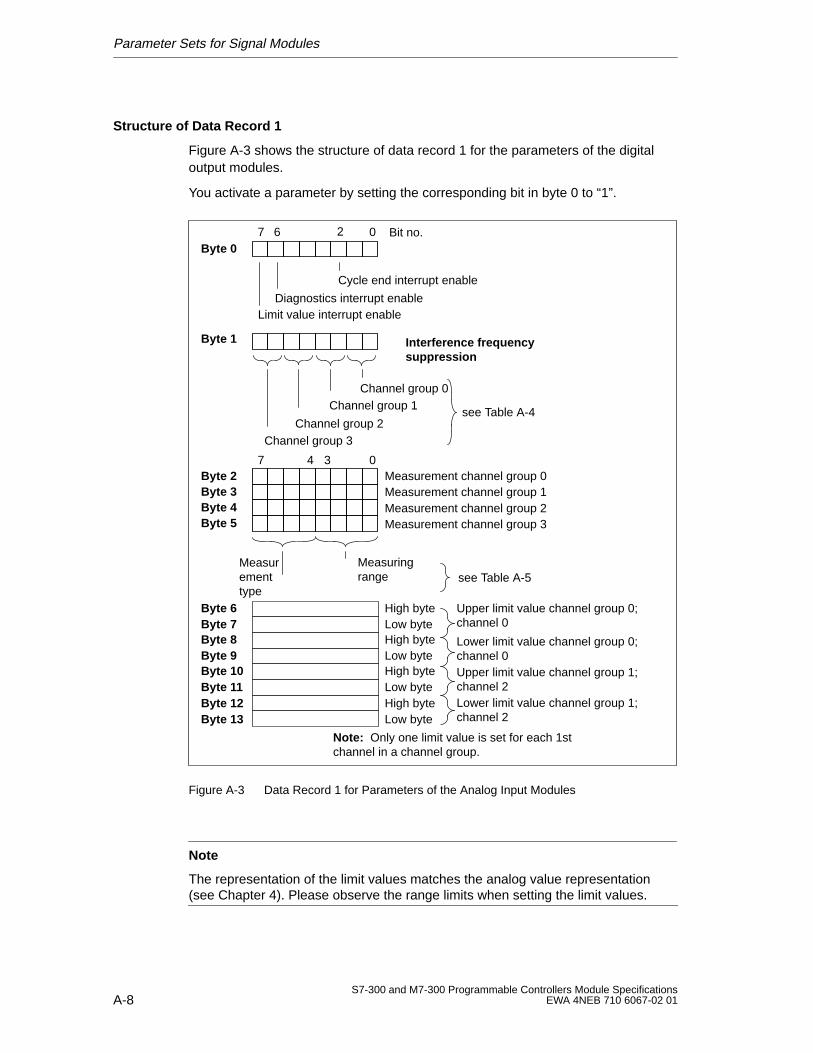
Parameter Sets for Signal Modules
A-8S7-300 and M7-300 Programmable Controllers Module Specifications
EWA 4NEB 710 6067-02 01
Structure of Data Record 1
Figure A-3 shows the structure of data record 1 for the parameters of the digitaloutput modules.
You activate a parameter by setting the corresponding bit in byte 0 to “1”.
Byte 07 6 0 Bit no.
Diagnostics interrupt enableLimit value interrupt enable
Byte 1 Interference frequencysuppression
Byte 2Byte 3Byte 4Byte 5
7 04 3Measurement channel group 0
Measurement channel group 2Measurement channel group 1
Measurement channel group 3
Measuringrange
Measurementtype
Low byte
Low byte
Low byte
Low byte
High byte
High byte
High byte
High byte
Byte 6Byte 7Byte 8Byte 9Byte 10Byte 11Byte 12Byte 13
see Table A-5
see Table A-4
Note: Only one limit value is set for each 1stchannel in a channel group.
Cycle end interrupt enable
2
Channel group 0Channel group 1
Channel group 2Channel group 3
Upper limit value channel group 0;channel 0
Lower limit value channel group 0;channel 0Upper limit value channel group 1;channel 2Lower limit value channel group 1;channel 2
Figure A-3 Data Record 1 for Parameters of the Analog Input Modules
Note
The representation of the limit values matches the analog value representation(see Chapter 4). Please observe the range limits when setting the limit values.
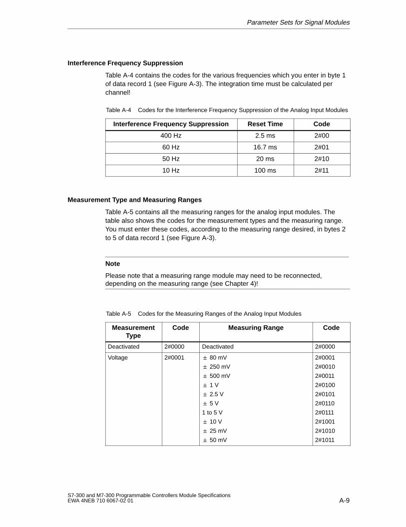
Parameter Sets for Signal Modules
A-9S7-300 and M7-300 Programmable Controllers Module SpecificationsEWA 4NEB 710 6067-02 01
Interference Frequency Suppression
Table A-4 contains the codes for the various frequencies which you enter in byte 1of data record 1 (see Figure A-3). The integration time must be calculated perchannel!
Table A-4 Codes for the Interference Frequency Suppression of the Analog Input Modules
Interference Frequency Suppression Reset Time Code
400 Hz 2.5 ms 2#00
60 Hz 16.7 ms 2#01
50 Hz 20 ms 2#10
10 Hz 100 ms 2#11
Measurement T ype and Measuring Ranges
Table A-5 contains all the measuring ranges for the analog input modules. Thetable also shows the codes for the measurement types and the measuring range.You must enter these codes, according to the measuring range desired, in bytes 2to 5 of data record 1 (see Figure A-3).
Note
Please note that a measuring range module may need to be reconnected,depending on the measuring range (see Chapter 4)!
Table A-5 Codes for the Measuring Ranges of the Analog Input Modules
MeasurementType
Code Measuring Range Code
Deactivated 2#0000 Deactivated 2#0000
Voltage 2#0001 80 mV
250 mV
500 mV
1 V
2.5 V
5 V
1 to 5 V
10 V
25 mV
50 mV
2#0001
2#0010
2#0011
2#0100
2#0101
2#0110
2#0111
2#1001
2#1010
2#1011
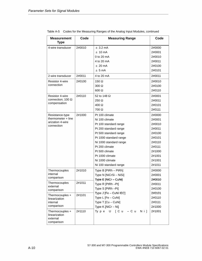
Parameter Sets for Signal Modules
A-10S7-300 and M7-300 Programmable Controllers Module Specifications
EWA 4NEB 710 6067-02 01
Table A-5 Codes for the Measuring Ranges of the Analog Input Modules, continued
MeasurementType
CodeMeasuring RangeCode
4-wire transducer 2#0010 3.2 mA
10 mA
0 to 20 mA
4 to 20 mA
20 mA
5 mA
2#0000
2#0001
2#0010
2#0011
2#0100
2#0101
2-wire transducer 2#0011 4 to 20 mA 2#0011
Resistor 4-wireconnection
2#0100 150
300
600
2#0010
2#0100
2#0110
Resistor 4-wireconnection; 100 compensation
2#0110 52 to 148
250
400
700
2#0001
2#0011
2#0101
2#0111
Resistance-typethermometer + linearization 4-wireconnection
2#1000 Pt 100 climate
Ni 100 climate
Pt 100 standard range
Pt 200 standard range
Pt 500 standard range
Pt 1000 standard range
Ni 1000 standard range
Pt 200 climate
Pt 500 climate
Pt 1000 climate
Ni 1000 climate
Ni 100 standard range
2#0000
2#0001
2#0010
2#0011
2#0100
2#0101
2#0110
2#0111
2#1000
2#1001
2#1001
2#1011
Thermocouplesinternalcomparison
2#1010 Type B [PtRh – PtRh]
Type N [NiCrSi – NiSi]
Type E [NiCr – CuNi]
2#0000
2#0001
2#0010Thermocouplesexternalcomparison
2#1011Type E [NiCr – CuNi]
Type R [PtRh –Pt]
Type S [PtRh –Pt]
Type J [Fe CuNi IEC]
2#0010
2#0011
2#0100
2#0101Thermocouples + linearizationinternalcomparison
2#1101Type J [Fe – CuNi IEC]
Type L [Fe – CuNi]
Type T [Cu – CuNi]
Type K [NiCr – Ni]
2#0101
2#0110
2#0111
2#1000
Thermocouples + linearizationexternalcomparison
2#1110
Type K [NiCr Ni]
Ty p e U [ C u – C u N i ]
2#1000
2#1001
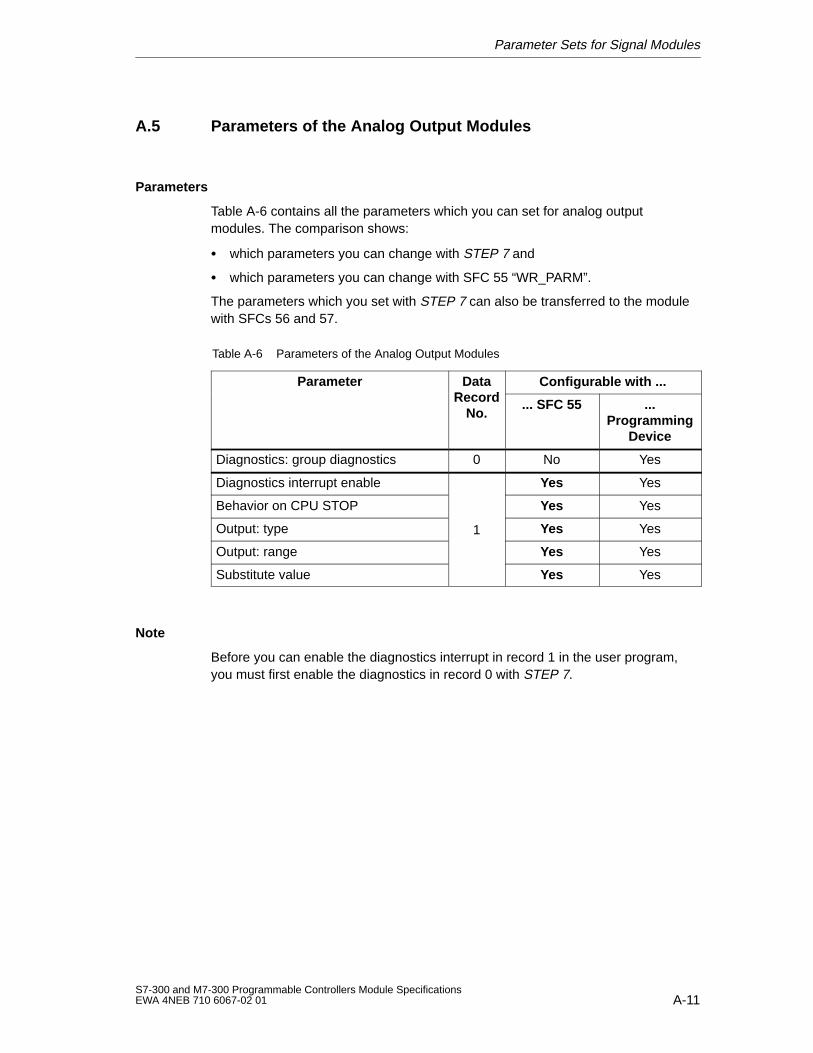
Parameter Sets for Signal Modules
A-11S7-300 and M7-300 Programmable Controllers Module SpecificationsEWA 4NEB 710 6067-02 01
A.5 Parameters of the Analog Output Modules
Parameters
Table A-6 contains all the parameters which you can set for analog outputmodules. The comparison shows:
which parameters you can change with STEP 7 and
which parameters you can change with SFC 55 “WR_PARM”.
The parameters which you set with STEP 7 can also be transferred to the modulewith SFCs 56 and 57.
Table A-6 Parameters of the Analog Output Modules
Parameter DataRecord
Configurable with ...Record
No.... SFC 55 ...
ProgrammingDevice
Diagnostics: group diagnostics 0 No Yes
Diagnostics interrupt enable Yes Yes
Behavior on CPU STOP Yes Yes
Output: type 1 Yes Yes
Output: range Yes Yes
Substitute value Yes Yes
Note
Before you can enable the diagnostics interrupt in record 1 in the user program,you must first enable the diagnostics in record 0 with STEP 7.
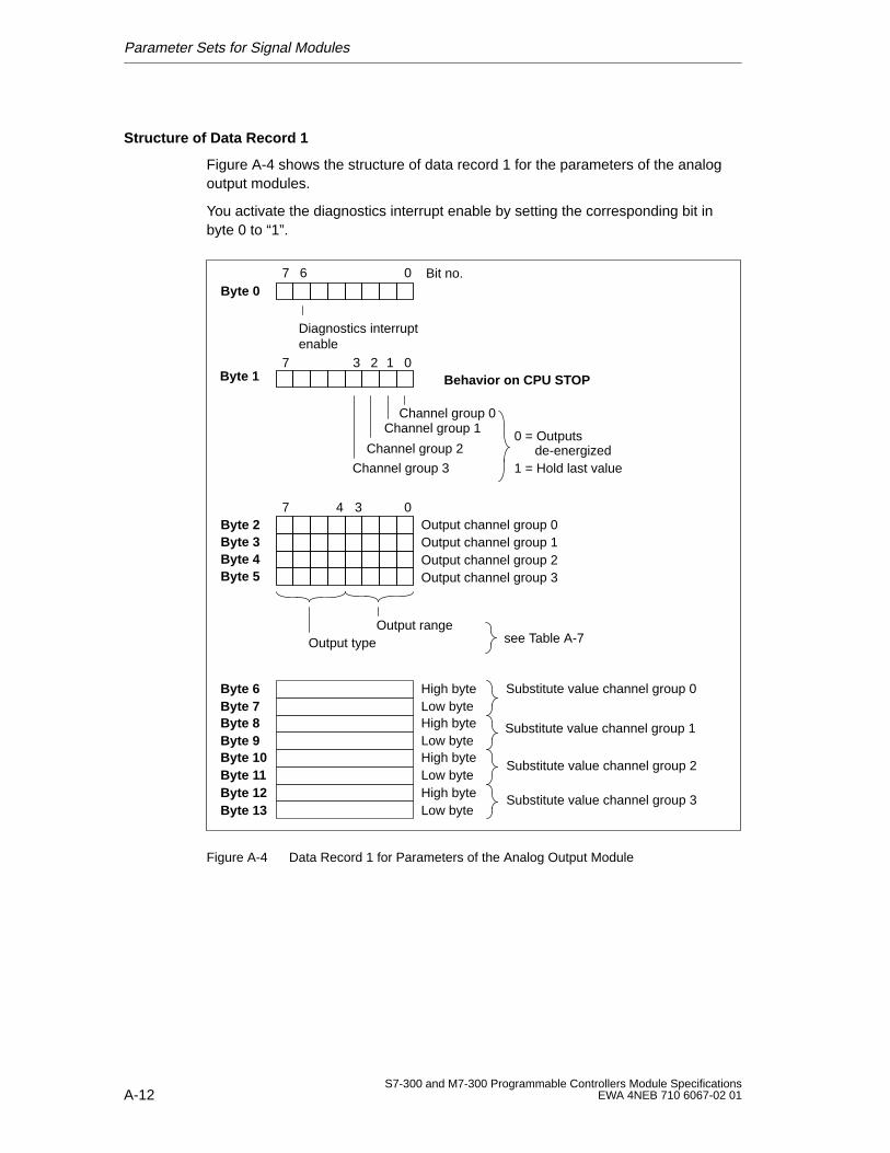
Parameter Sets for Signal Modules
A-12S7-300 and M7-300 Programmable Controllers Module Specifications
EWA 4NEB 710 6067-02 01
Structure of Data Record 1
Figure A-4 shows the structure of data record 1 for the parameters of the analogoutput modules.
You activate the diagnostics interrupt enable by setting the corresponding bit inbyte 0 to “1”.
Byte 07 6 0 Bit no.
Byte 1 Behavior on CPU STOP
Byte 2Byte 3Byte 4Byte 5
7 04 3Output channel group 0
Output channel group 2Output channel group 1
Output channel group 3
Output rangeOutput type
Substitute value channel group 0Low byte
Low byte
Low byte
Low byte
High byte
High byte
High byte
High byte
Byte 6Byte 7Byte 8Byte 9Byte 10Byte 11Byte 12Byte 13
7 03 2 1
Diagnostics interruptenable
see Table A-7
0 = Outputsde-energized
1 = Hold last value
Substitute value channel group 1
Substitute value channel group 2
Substitute value channel group 3
Channel group 3
Channel group 0Channel group 1
Channel group 2
Figure A-4 Data Record 1 for Parameters of the Analog Output Module
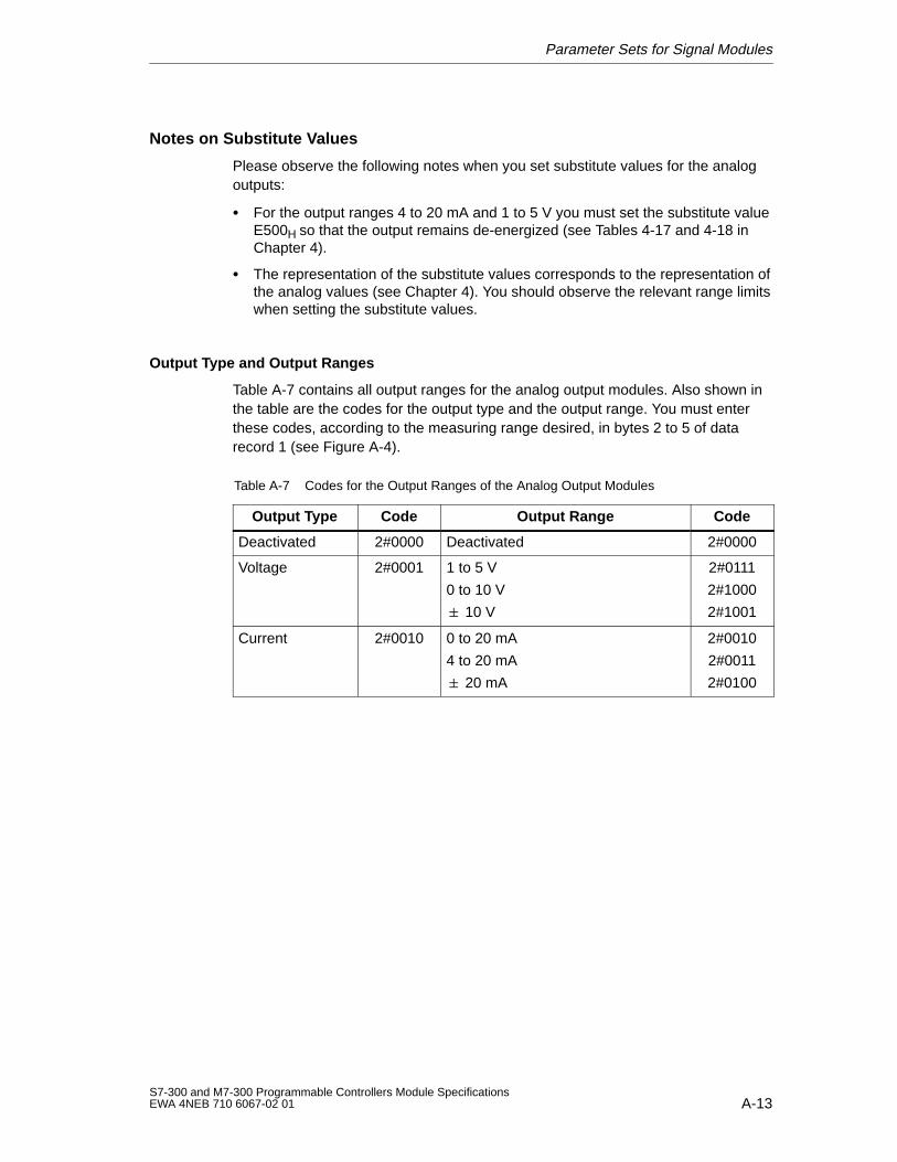
Parameter Sets for Signal Modules
A-13S7-300 and M7-300 Programmable Controllers Module SpecificationsEWA 4NEB 710 6067-02 01
Notes on Substitute Values
Please observe the following notes when you set substitute values for the analogoutputs:
For the output ranges 4 to 20 mA and 1 to 5 V you must set the substitute valueE500H so that the output remains de-energized (see Tables 4-17 and 4-18 inChapter 4).
The representation of the substitute values corresponds to the representation ofthe analog values (see Chapter 4). You should observe the relevant range limitswhen setting the substitute values.
Output Type and Output Ranges
Table A-7 contains all output ranges for the analog output modules. Also shown inthe table are the codes for the output type and the output range. You must enterthese codes, according to the measuring range desired, in bytes 2 to 5 of datarecord 1 (see Figure A-4).
Table A-7 Codes for the Output Ranges of the Analog Output Modules
Output Type Code Output Range Code
Deactivated 2#0000 Deactivated 2#0000
Voltage 2#0001 1 to 5 V
0 to 10 V
10 V
2#0111
2#1000
2#1001
Current 2#0010 0 to 20 mA
4 to 20 mA
20 mA
2#0010
2#0011
2#0100

Parameter Sets for Signal Modules
A-14S7-300 and M7-300 Programmable Controllers Module Specifications
EWA 4NEB 710 6067-02 01
B-1S7-300 and M7-300 Programmable Controllers Module SpecificationsEWA 4NEB 710 6067-02 01
Diagnostics Data of the Signal Modules
In this Appendix
This appendix describes the configuration of the diagnostics data in the systemdata. You must be familiar with this configuration if you want to evaluate thediagnostics data of the signal module in the STEP 7 user program.
Further References
The reference manual System and Standard Functions includes an extensivedescription of the evaluation principle for the diagnostics data of signal modules inthe user program, in addition to a description of the SFCs that can be used for thispurpose.
Data Records 0 and 1 of the System Data
The diagnostics data of a module can be up to 16 bytes long and are located indata records 0 and 1 of the system data area:
Data record 0 contains 4 bytes of diagnostics data describing the current statusof an S7-300.
Data record 1 contains
– the 4 bytes of diagnostics data of an S7-300 that are also located in datarecord 0 and
– up to 12 bytes of module-specific diagnostics data.
Configuration and Contents of Diagnostics Data
The configuration and the contents of the individual bytes of the diagnostics dataare described below.
The following general rule applies: If an error occurs, the corresponding bit is set to“1”.
B
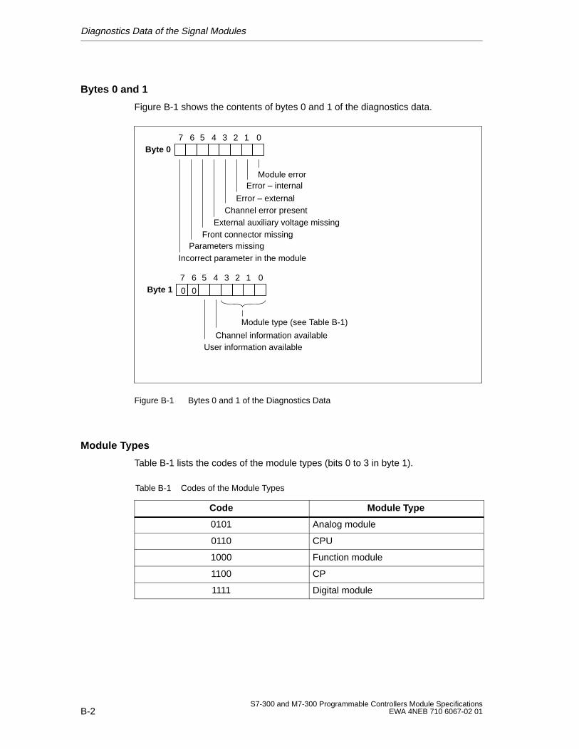
Diagnostics Data of the Signal Modules
B-2S7-300 and M7-300 Programmable Controllers Module Specifications
EWA 4NEB 710 6067-02 01
Bytes 0 and 1
Figure B-1 shows the contents of bytes 0 and 1 of the diagnostics data.
Byte 07 6 0
Module errorError – internal
Error – externalChannel error present
External auxiliary voltage missingFront connector missing
Parameters missingIncorrect parameter in the module
5 4 3 2 1
Byte 17 6 0
Channel information availableUser information available
5 4 3 2 1
Module type (see Table B-1)
00
Figure B-1 Bytes 0 and 1 of the Diagnostics Data
Module Types
Table B-1 lists the codes of the module types (bits 0 to 3 in byte 1).
Table B-1 Codes of the Module Types
Code Module Type
0101 Analog module
0110 CPU
1000 Function module
1100 CP
1111 Digital module
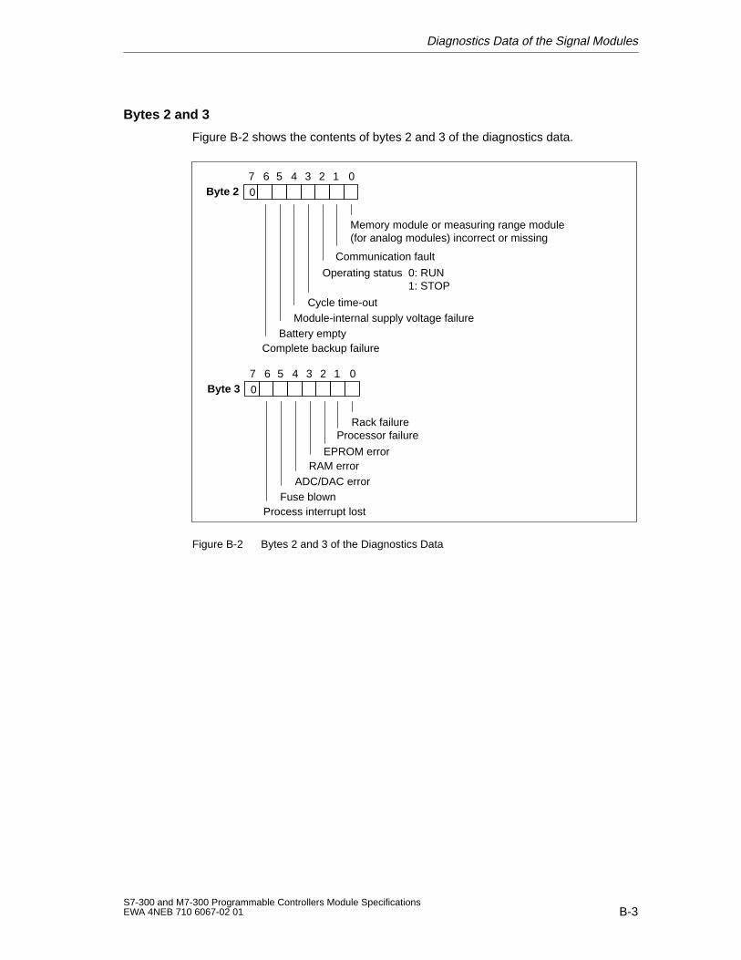
Diagnostics Data of the Signal Modules
B-3S7-300 and M7-300 Programmable Controllers Module SpecificationsEWA 4NEB 710 6067-02 01
Bytes 2 and 3
Figure B-2 shows the contents of bytes 2 and 3 of the diagnostics data.
Byte 27 6 0
Memory module or measuring range module(for analog modules) incorrect or missing
Communication fault
Operating status 0: RUN1: STOP
Cycle time-outModule-internal supply voltage failure
Battery emptyComplete backup failure
5 4 3 2 1
0
Byte 37 6 0
Rack failureProcessor failure
EPROM errorRAM error
ADC/DAC errorFuse blown
Process interrupt lost
5 4 3 2 1
0
Figure B-2 Bytes 2 and 3 of the Diagnostics Data
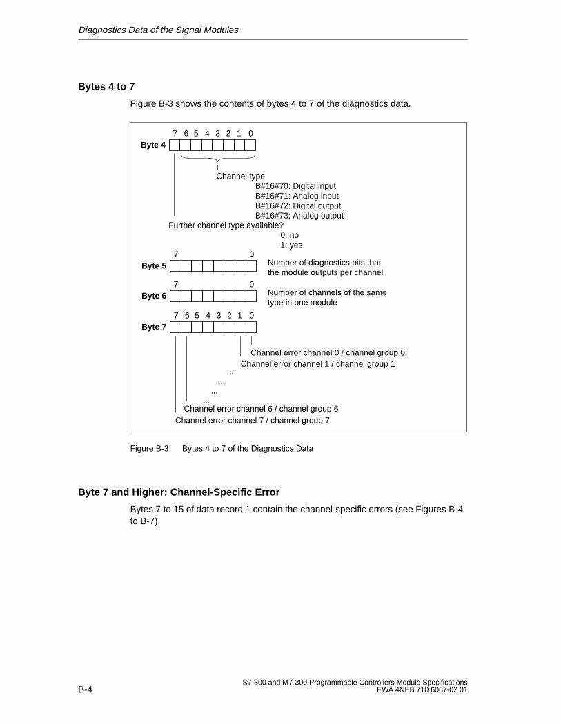
Diagnostics Data of the Signal Modules
B-4S7-300 and M7-300 Programmable Controllers Module Specifications
EWA 4NEB 710 6067-02 01
Bytes 4 to 7
Figure B-3 shows the contents of bytes 4 to 7 of the diagnostics data.
Byte 47 6 05 4 3 2 1
Byte 57 0
Further channel type available?0: no1: yes
Channel typeB#16#70: Digital inputB#16#71: Analog inputB#16#72: Digital outputB#16#73: Analog output
Number of diagnostics bits thatthe module outputs per channel
Byte 67 0
Number of channels of the sametype in one module
Byte 77 6 0
Channel error channel 6 / channel group 6
5 4 3 2 1
......
......
Channel error channel 7 / channel group 7
Channel error channel 1 / channel group 1Channel error channel 0 / channel group 0
Figure B-3 Bytes 4 to 7 of the Diagnostics Data
Byte 7 and Higher: Channel-Specific Error
Bytes 7 to 15 of data record 1 contain the channel-specific errors (see Figures B-4to B-7).
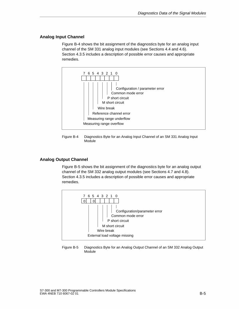
Diagnostics Data of the Signal Modules
B-5S7-300 and M7-300 Programmable Controllers Module SpecificationsEWA 4NEB 710 6067-02 01
Analog Input Channel
Figure B-4 shows the bit assignment of the diagnostics byte for an analog inputchannel of the SM 331 analog input modules (see Sections 4.4 and 4.6).Section 4.3.5 includes a description of possible error causes and appropriateremedies.
7 6 0
Configuration / parameter errorCommon mode error
Wire break
Measuring range underflowMeasuring range overflow
5 4 3 2 1
P short circuitM short circuit
Reference channel error
Figure B-4 Diagnostics Byte for an Analog Input Channel of an SM 331 Analog InputModule
Analog Output Channel
Figure B-5 shows the bit assignment of the diagnostics byte for an analog outputchannel of the SM 332 analog output modules (see Sections 4.7 and 4.8).Section 4.3.5 includes a description of possible error causes and appropriateremedies.
7 6 0
Configuration/parameter error
M short circuitWire break
5 4 3 2 1
00
Common mode errorP short circuit
External load voltage missing
Figure B-5 Diagnostics Byte for an Analog Output Channel of an SM 332 Analog OutputModule
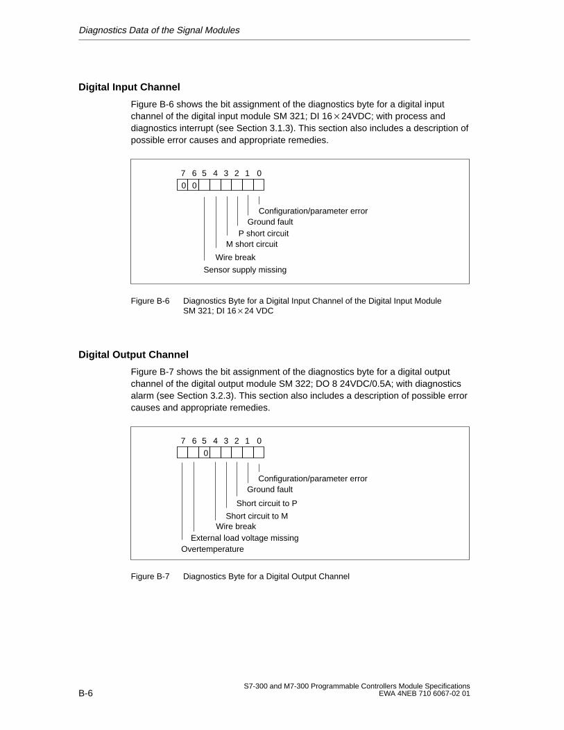
Diagnostics Data of the Signal Modules
B-6S7-300 and M7-300 Programmable Controllers Module Specifications
EWA 4NEB 710 6067-02 01
Digital Input Channel
Figure B-6 shows the bit assignment of the diagnostics byte for a digital inputchannel of the digital input module SM 321; DI 1624VDC; with process anddiagnostics interrupt (see Section 3.1.3). This section also includes a description ofpossible error causes and appropriate remedies.
7 6 0
Sensor supply missing
5 4 3 2 1
00
Configuration/parameter errorGround fault
Wire break
P short circuitM short circuit
Figure B-6 Diagnostics Byte for a Digital Input Channel of the Digital Input ModuleSM 321; DI 1624 VDC
Digital Output Channel
Figure B-7 shows the bit assignment of the diagnostics byte for a digital outputchannel of the digital output module SM 322; DO 8 24VDC/0.5A; with diagnosticsalarm (see Section 3.2.3). This section also includes a description of possible errorcauses and appropriate remedies.
7 6 0
Short circuit to P
Short circuit to MWire break
5 4 3 2 1
0
Configuration/parameter errorGround fault
OvertemperatureExternal load voltage missing
Figure B-7 Diagnostics Byte for a Digital Output Channel
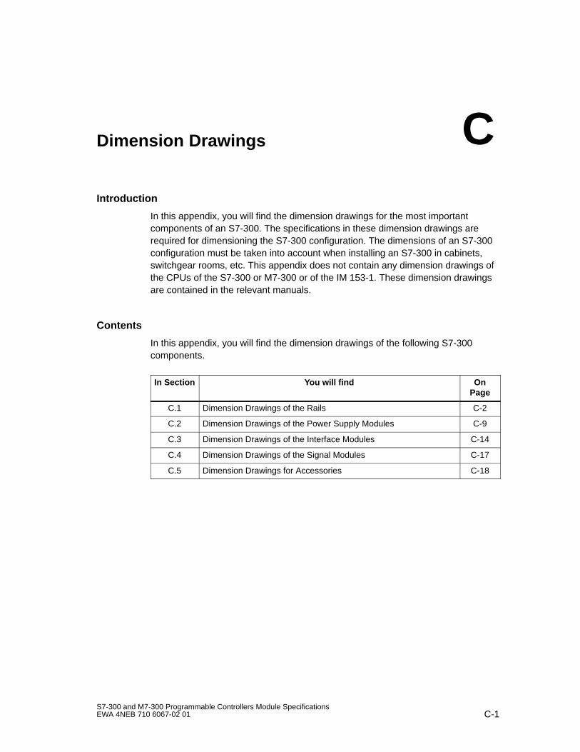
C-1S7-300 and M7-300 Programmable Controllers Module SpecificationsEWA 4NEB 710 6067-02 01
Dimension Drawings
Introduction
In this appendix, you will find the dimension drawings for the most importantcomponents of an S7-300. The specifications in these dimension drawings arerequired for dimensioning the S7-300 configuration. The dimensions of an S7-300configuration must be taken into account when installing an S7-300 in cabinets,switchgear rooms, etc. This appendix does not contain any dimension drawings ofthe CPUs of the S7-300 or M7-300 or of the IM 153-1. These dimension drawingsare contained in the relevant manuals.
Contents
In this appendix, you will find the dimension drawings of the following S7-300components.
In Section You will find OnPage
C.1 Dimension Drawings of the Rails C-2
C.2 Dimension Drawings of the Power Supply Modules C-9
C.3 Dimension Drawings of the Interface Modules C-14
C.4 Dimension Drawings of the Signal Modules C-17
C.5 Dimension Drawings for Accessories C-18
C
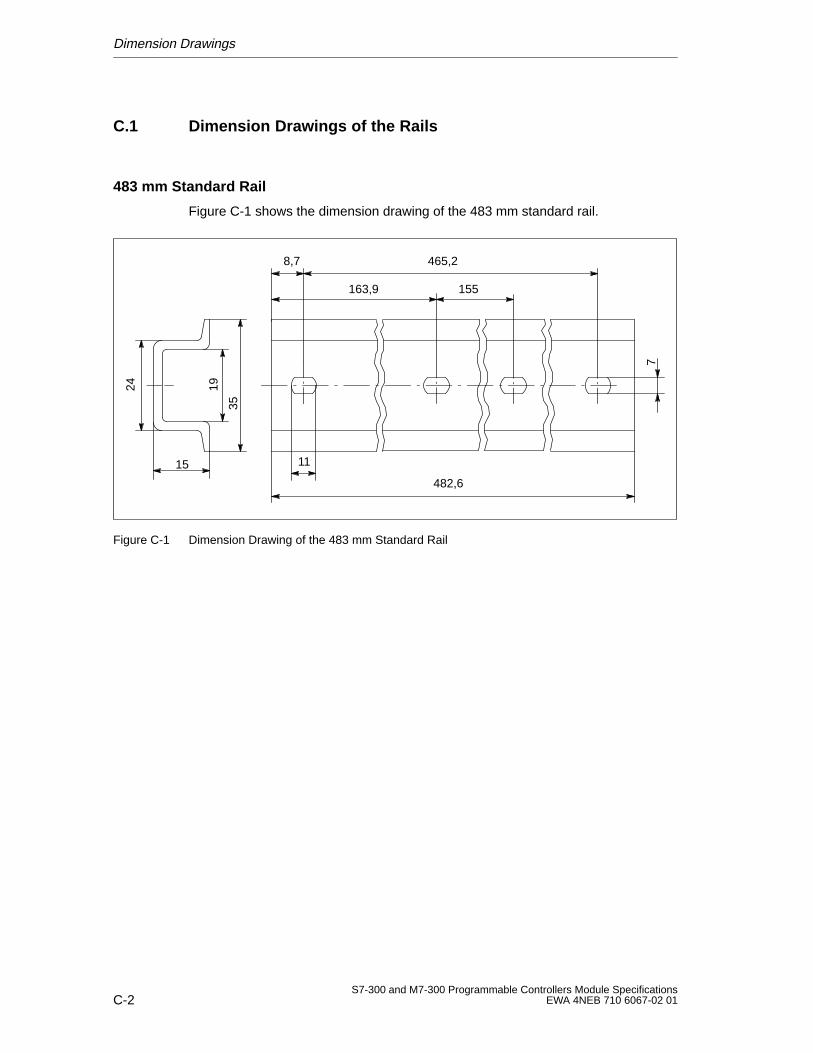
Dimension Drawings
C-2S7-300 and M7-300 Programmable Controllers Module Specifications
EWA 4NEB 710 6067-02 01
C.1 Dimension Drawings of the Rails
483 mm Standard Rail
Figure C-1 shows the dimension drawing of the 483 mm standard rail.
15
19
35
24
8,7 465,2
163,9 155
11
482,6
7
Figure C-1 Dimension Drawing of the 483 mm Standard Rail
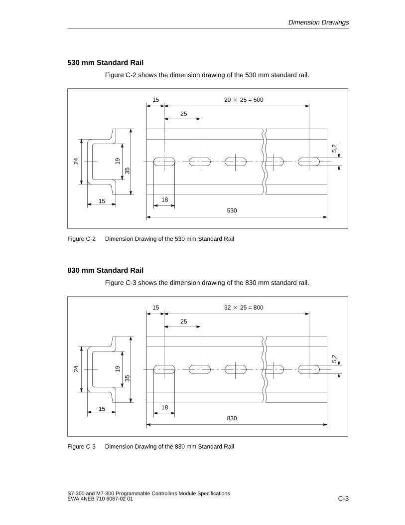
Dimension Drawings
C-3S7-300 and M7-300 Programmable Controllers Module SpecificationsEWA 4NEB 710 6067-02 01
530 mm Standard Rail
Figure C-2 shows the dimension drawing of the 530 mm standard rail.
15
19
35
24
15 20 25 = 500
25
18
530
5,2
Figure C-2 Dimension Drawing of the 530 mm Standard Rail
830 mm Standard Rail
Figure C-3 shows the dimension drawing of the 830 mm standard rail.
15
19
35
24
15 32 25 = 800
25
18
830
5,2
Figure C-3 Dimension Drawing of the 830 mm Standard Rail
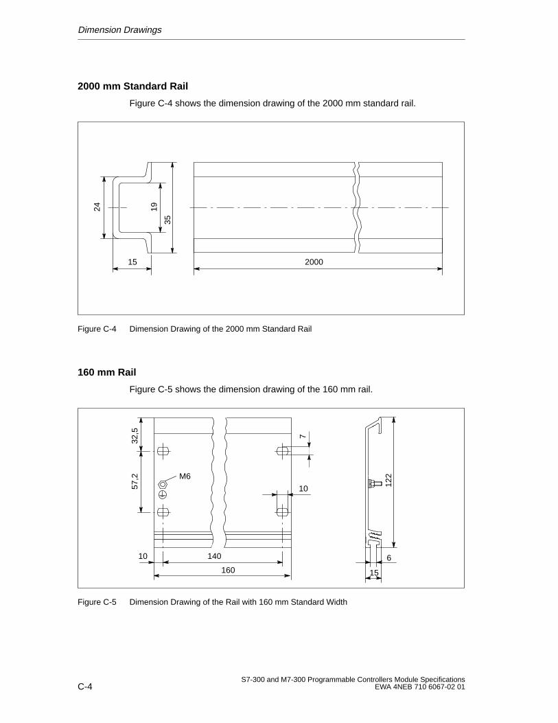
Dimension Drawings
C-4S7-300 and M7-300 Programmable Controllers Module Specifications
EWA 4NEB 710 6067-02 01
2000 mm Standard Rail
Figure C-4 shows the dimension drawing of the 2000 mm standard rail.
15
19
35
24
2000
Figure C-4 Dimension Drawing of the 2000 mm Standard Rail
160 mm Rail
Figure C-5 shows the dimension drawing of the 160 mm rail.
14010
57,2
32,5
160 15
6
122
7
10
M6
Figure C-5 Dimension Drawing of the Rail with 160 mm Standard Width
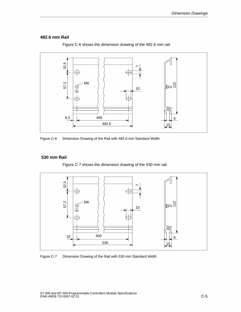
Dimension Drawings
C-5S7-300 and M7-300 Programmable Controllers Module SpecificationsEWA 4NEB 710 6067-02 01
482.6 mm Rail
Figure C-6 shows the dimension drawing of the 482.6 mm rail.
8,3
15
6466
57,2
32,5
482,6
122
7
10
M6
Figure C-6 Dimension Drawing of the Rail with 482.6 mm Standard Width
530 mm Rail
Figure C-7 shows the dimension drawing of the 530 mm rail.
50015
57,2
32,5
530 15
6
122
7
10
M6
Figure C-7 Dimension Drawing of the Rail with 530 mm Standard Width
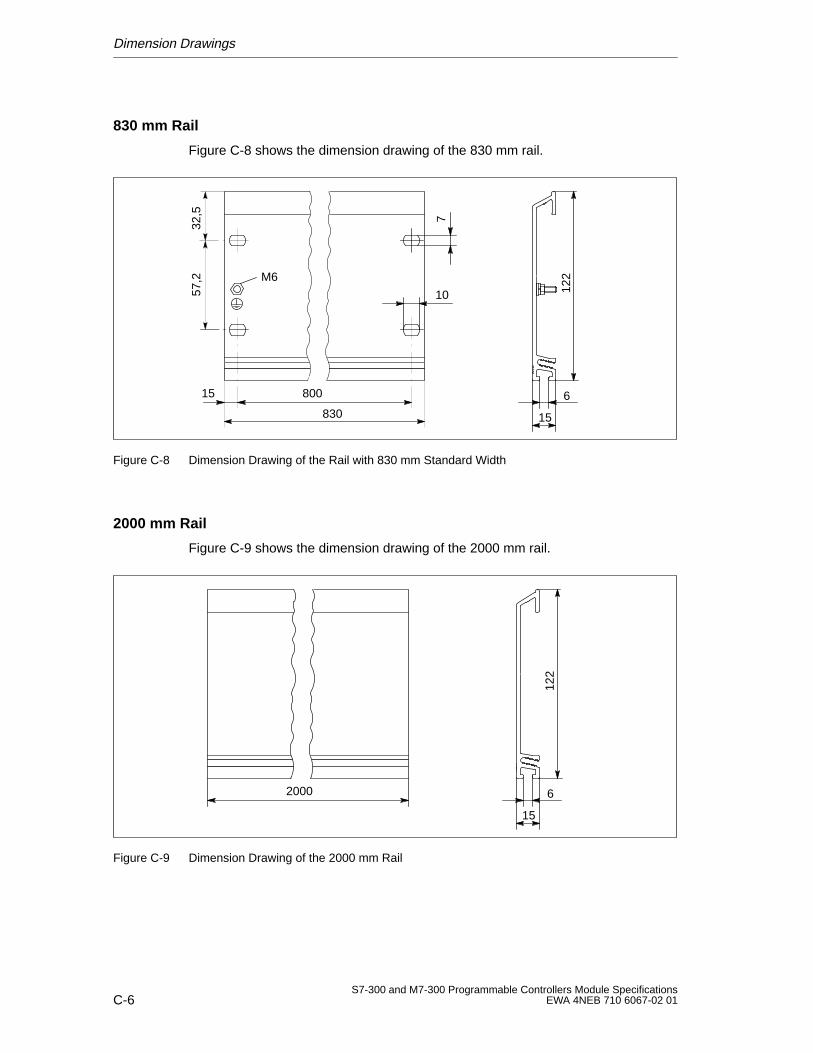
Dimension Drawings
C-6S7-300 and M7-300 Programmable Controllers Module Specifications
EWA 4NEB 710 6067-02 01
830 mm Rail
Figure C-8 shows the dimension drawing of the 830 mm rail.
80015
57,2
32,5
830 15
6
122
7
10
M6
Figure C-8 Dimension Drawing of the Rail with 830 mm Standard Width
2000 mm Rail
Figure C-9 shows the dimension drawing of the 2000 mm rail.
2000
15
6
122
Figure C-9 Dimension Drawing of the 2000 mm Rail
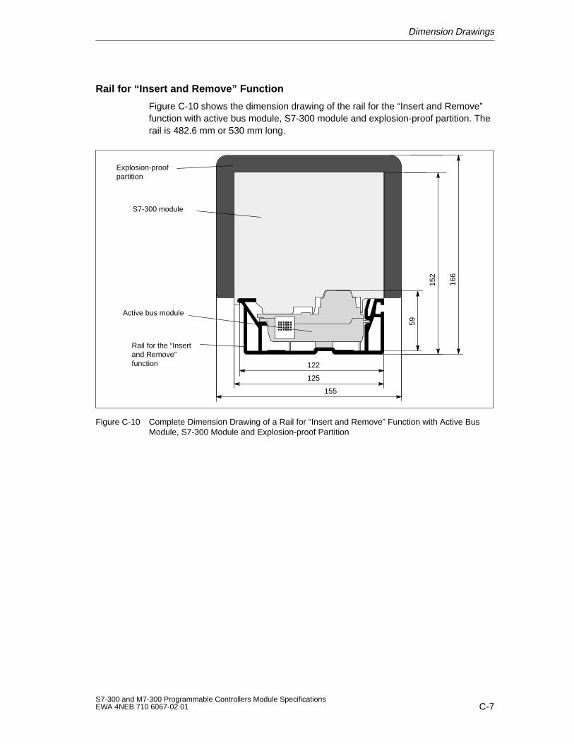
Dimension Drawings
C-7S7-300 and M7-300 Programmable Controllers Module SpecificationsEWA 4NEB 710 6067-02 01
Rail for “Insert and Remove” Function
Figure C-10 shows the dimension drawing of the rail for the “Insert and Remove”function with active bus module, S7-300 module and explosion-proof partition. Therail is 482.6 mm or 530 mm long.
Explosion-proofpartition
S7-300 module
Active bus module
Rail for the “Insertand Remove”function
152
166
122
125
155
59Figure C-10 Complete Dimension Drawing of a Rail for “Insert and Remove” Function with Active Bus
Module, S7-300 Module and Explosion-proof Partition
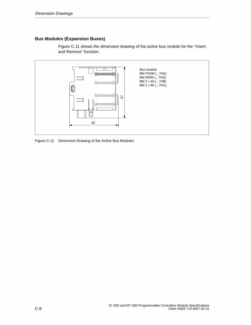
Dimension Drawings
C-8S7-300 and M7-300 Programmable Controllers Module Specifications
EWA 4NEB 710 6067-02 01
Bus Modules (Expansion Buses)
Figure C-11 shows the dimension drawing of the active bus module for the “Insertand Remove” function.
Bus moduleBM PS/IM (...7HA)BM IM/IM (...7HD)BM 240 (...7HB)BM 180 (...7HC)
9792
Figure C-11 Dimension Drawing of the Active Bus Modules
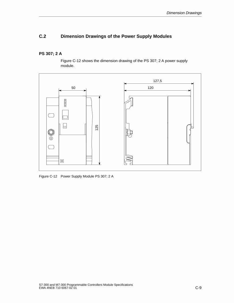
Dimension Drawings
C-9S7-300 and M7-300 Programmable Controllers Module SpecificationsEWA 4NEB 710 6067-02 01
C.2 Dimension Drawings of the Power Supply Modules
PS 307; 2 A
Figure C-12 shows the dimension drawing of the PS 307; 2 A power supplymodule.
50 120
127,5
125
Figure C-12 Power Supply Module PS 307; 2 A
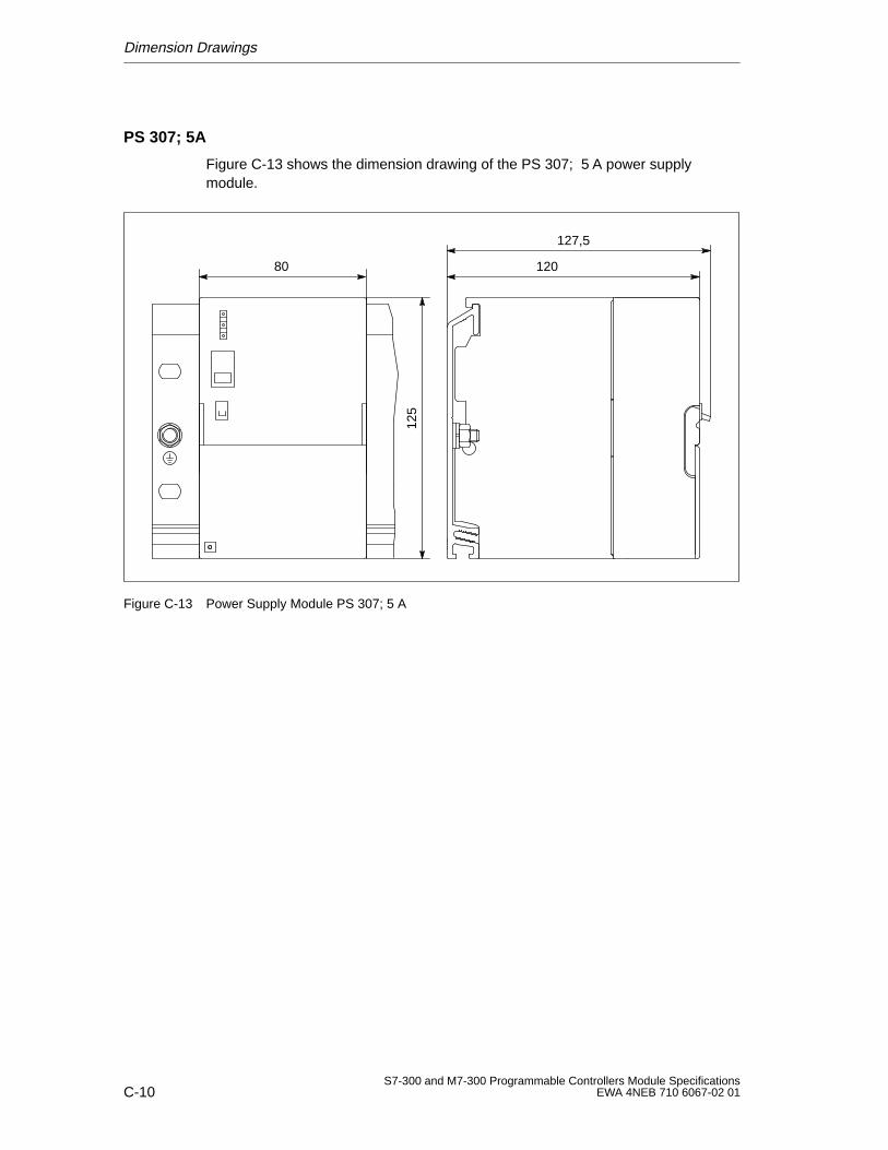
Dimension Drawings
C-10S7-300 and M7-300 Programmable Controllers Module Specifications
EWA 4NEB 710 6067-02 01
PS 307; 5A
Figure C-13 shows the dimension drawing of the PS 307; 5 A power supplymodule.
120
127,5
125
80
Figure C-13 Power Supply Module PS 307; 5 A
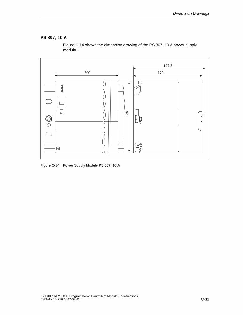
Dimension Drawings
C-11S7-300 and M7-300 Programmable Controllers Module SpecificationsEWA 4NEB 710 6067-02 01
PS 307; 10 A
Figure C-14 shows the dimension drawing of the PS 307; 10 A power supplymodule.
120
127,5
200
125
Figure C-14 Power Supply Module PS 307; 10 A
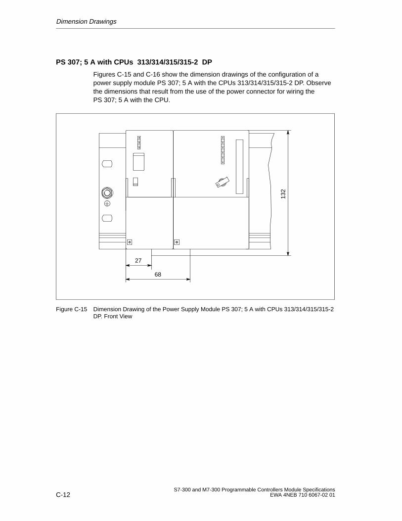
Dimension Drawings
C-12S7-300 and M7-300 Programmable Controllers Module Specifications
EWA 4NEB 710 6067-02 01
PS 307; 5 A with CPUs 313/314/315/315-2 DP
Figures C-15 and C-16 show the dimension drawings of the configuration of apower supply module PS 307; 5 A with the CPUs 313/314/315/315-2 DP. Observethe dimensions that result from the use of the power connector for wiring thePS 307; 5 A with the CPU.
27
68
132
Figure C-15 Dimension Drawing of the Power Supply Module PS 307; 5 A with CPUs 313/314/315/315-2DP. Front View
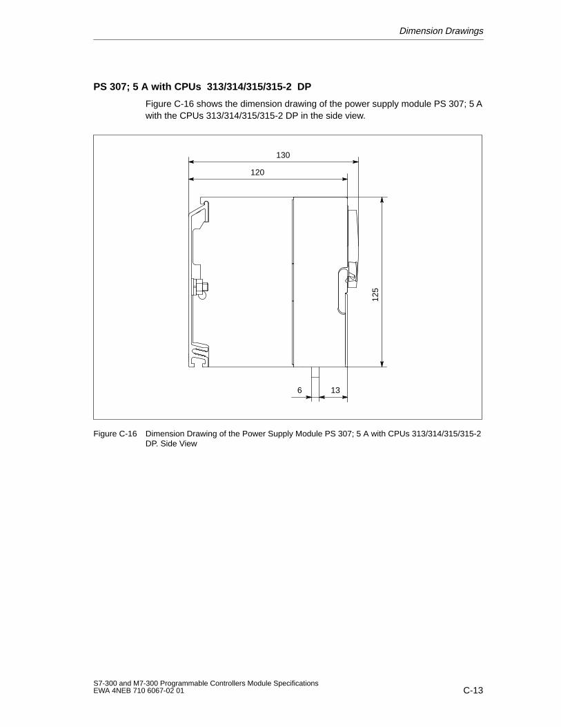
Dimension Drawings
C-13S7-300 and M7-300 Programmable Controllers Module SpecificationsEWA 4NEB 710 6067-02 01
PS 307; 5 A with CPUs 313/314/315/315-2 DP
Figure C-16 shows the dimension drawing of the power supply module PS 307; 5 Awith the CPUs 313/314/315/315-2 DP in the side view.
125
13
130
120
6
Figure C-16 Dimension Drawing of the Power Supply Module PS 307; 5 A with CPUs 313/314/315/315-2DP. Side View
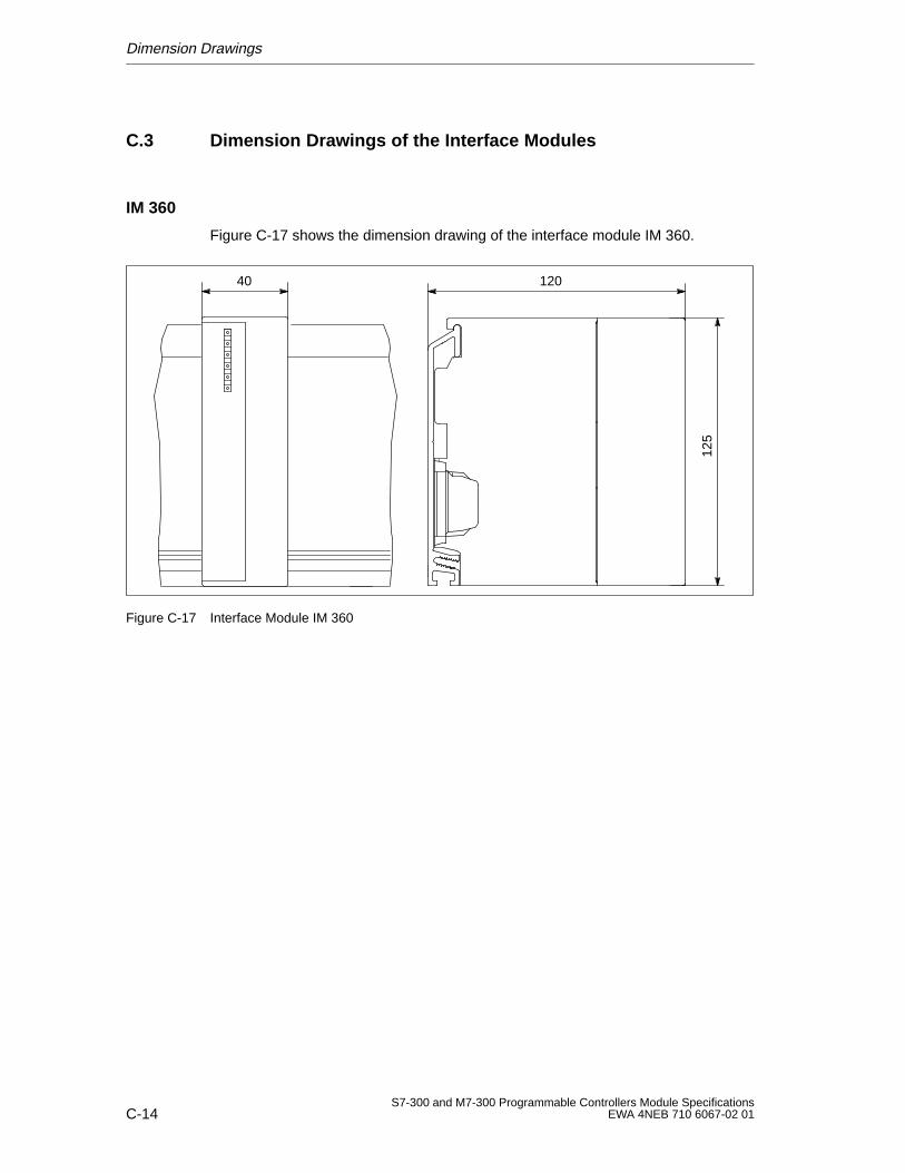
Dimension Drawings
C-14S7-300 and M7-300 Programmable Controllers Module Specifications
EWA 4NEB 710 6067-02 01
C.3 Dimension Drawings of the Interface Modules
IM 360
Figure C-17 shows the dimension drawing of the interface module IM 360.
125
12040
Figure C-17 Interface Module IM 360
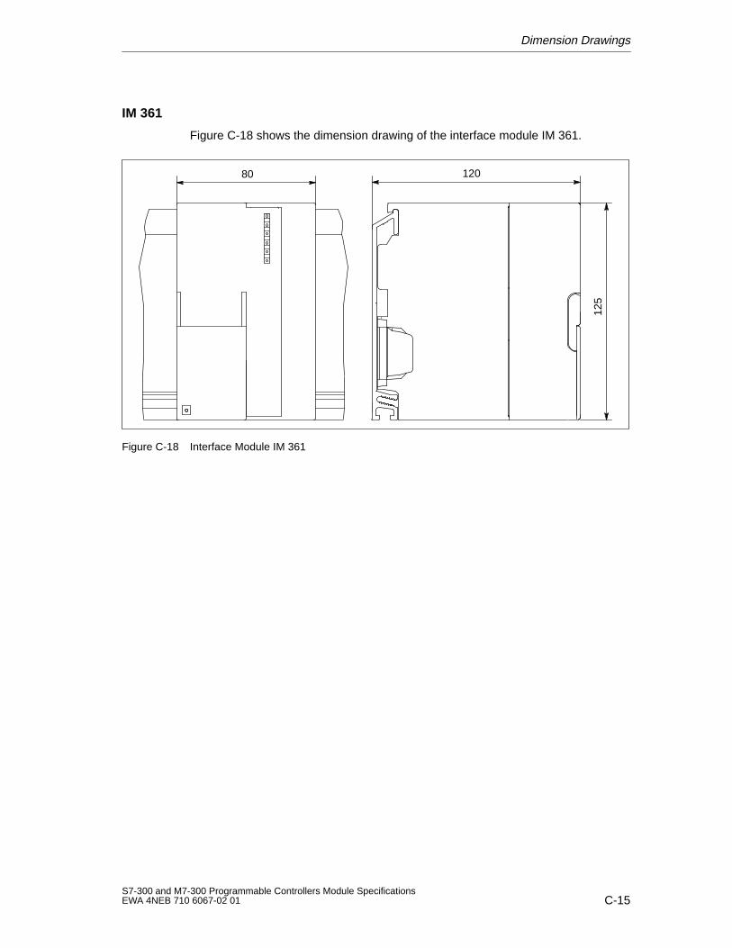
Dimension Drawings
C-15S7-300 and M7-300 Programmable Controllers Module SpecificationsEWA 4NEB 710 6067-02 01
IM 361
Figure C-18 shows the dimension drawing of the interface module IM 361.
125
12080
Figure C-18 Interface Module IM 361
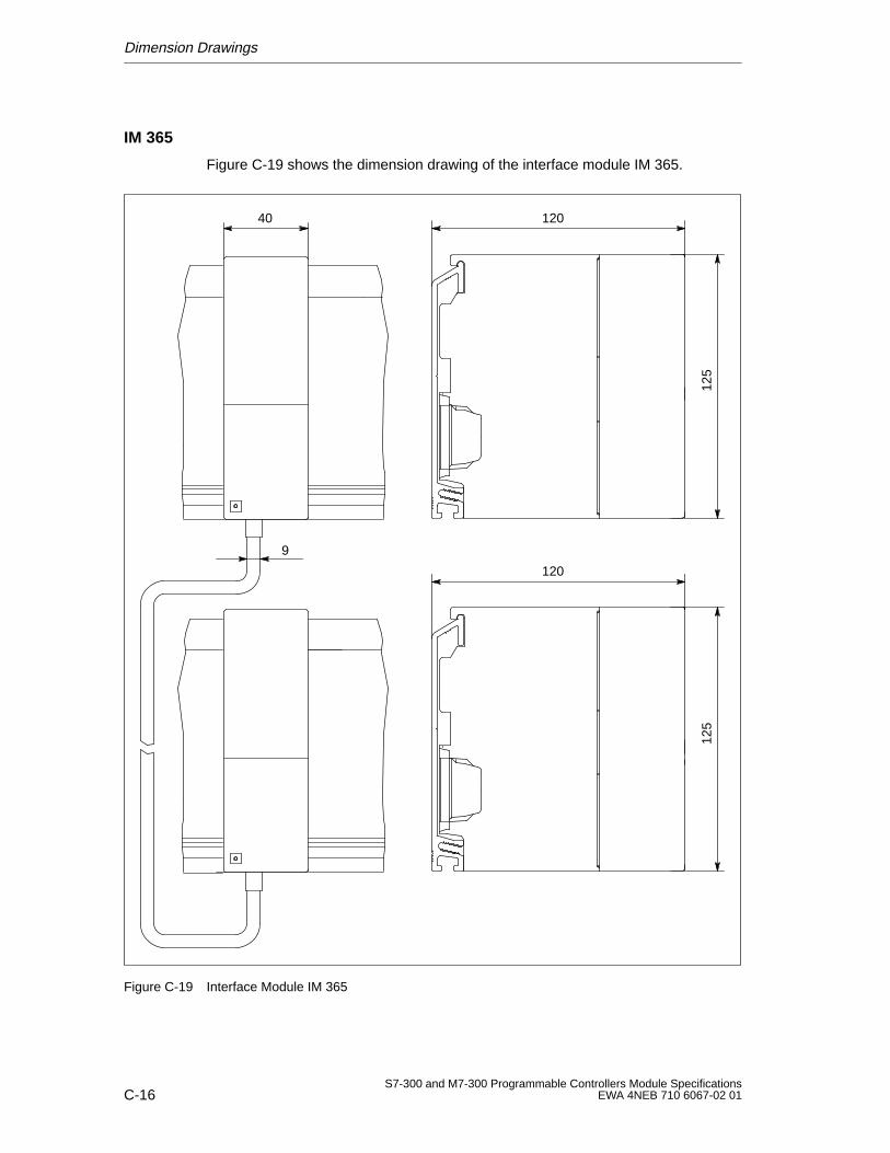
Dimension Drawings
C-16S7-300 and M7-300 Programmable Controllers Module Specifications
EWA 4NEB 710 6067-02 01
IM 365
Figure C-19 shows the dimension drawing of the interface module IM 365.
125
120
125
120
40
9
Figure C-19 Interface Module IM 365
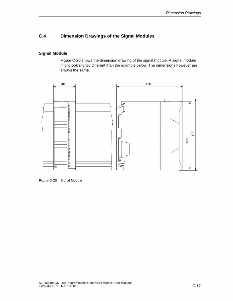
Dimension Drawings
C-17S7-300 and M7-300 Programmable Controllers Module SpecificationsEWA 4NEB 710 6067-02 01
C.4 Dimension Drawings of the Signal Modules
Signal Module
Figure C-20 shows the dimension drawing of the signal module. A signal modulemight look slightly different than the example below. The dimensions however arealways the same.
125
12040
130
Figure C-20 Signal Module
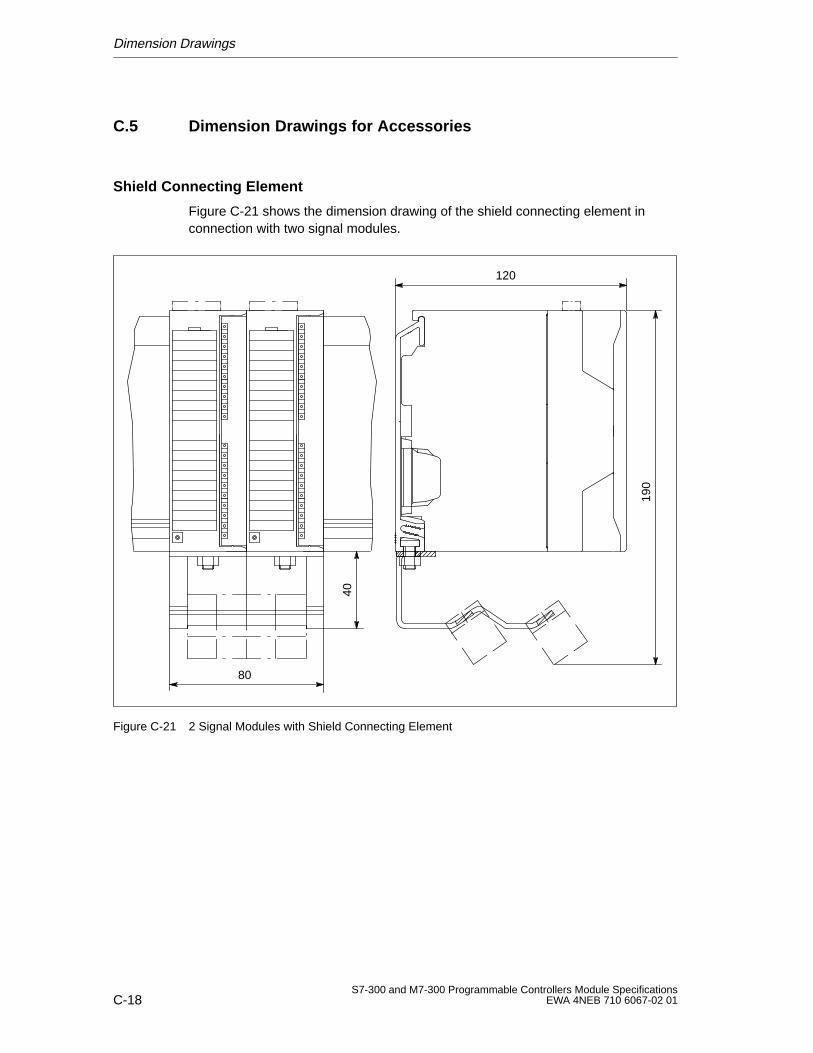
Dimension Drawings
C-18S7-300 and M7-300 Programmable Controllers Module Specifications
EWA 4NEB 710 6067-02 01
C.5 Dimension Drawings for Accessories
Shield Connecting Element
Figure C-21 shows the dimension drawing of the shield connecting element inconnection with two signal modules.
190
80
40
120
Figure C-21 2 Signal Modules with Shield Connecting Element
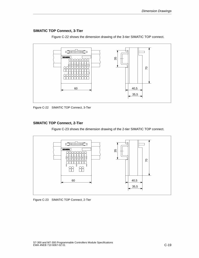
Dimension Drawings
C-19S7-300 and M7-300 Programmable Controllers Module SpecificationsEWA 4NEB 710 6067-02 01
SIMATIC TOP Connect, 3-Tier
Figure C-22 shows the dimension drawing of the 3-tier SIMATIC TOP connect.
70
60 40,5
35,5
35
Figure C-22 SIMATIC TOP Connect, 3-Tier
SIMATIC TOP Connect, 2-Tier
Figure C-23 shows the dimension drawing of the 2-tier SIMATIC TOP connect.
70
60 40,5
35,5
35
Figure C-23 SIMATIC TOP Connect, 2-Tier
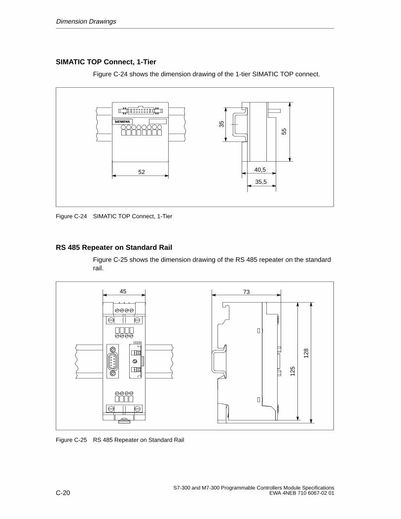
Dimension Drawings
C-20S7-300 and M7-300 Programmable Controllers Module Specifications
EWA 4NEB 710 6067-02 01
SIMATIC TOP Connect, 1-Tier
Figure C-24 shows the dimension drawing of the 1-tier SIMATIC TOP connect.
55
52 40,5
35,5
35Figure C-24 SIMATIC TOP Connect, 1-Tier
RS 485 Repeater on Standard Rail
Figure C-25 shows the dimension drawing of the RS 485 repeater on the standardrail.
7312
5
128
45
Figure C-25 RS 485 Repeater on Standard Rail
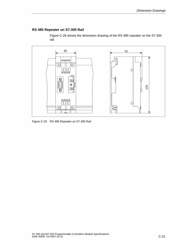
Dimension Drawings
C-21S7-300 and M7-300 Programmable Controllers Module SpecificationsEWA 4NEB 710 6067-02 01
RS 485 Repeater on S7-300 Rail
Figure C-26 shows the dimension drawing of the RS 485 repeater on the S7-300rail.
125
7045
Figure C-26 RS 485 Repeater on S7-300 Rail

Dimension Drawings
C-22S7-300 and M7-300 Programmable Controllers Module Specifications
EWA 4NEB 710 6067-02 01
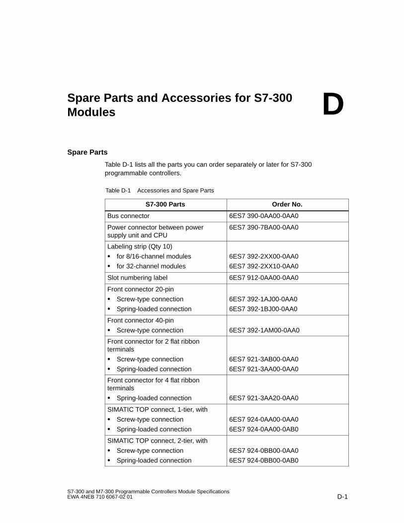
D-1S7-300 and M7-300 Programmable Controllers Module SpecificationsEWA 4NEB 710 6067-02 01
Spare Parts and Accessories for S7-300Modules
Spare Parts
Table D-1 lists all the parts you can order separately or later for S7-300programmable controllers.
Table D-1 Accessories and Spare Parts
S7-300 Parts Order No.
Bus connector 6ES7 390-0AA00-0AA0
Power connector between powersupply unit and CPU
6ES7 390-7BA00-0AA0
Labeling strip (Qty 10)
for 8/16-channel modules
for 32-channel modules
6ES7 392-2XX00-0AA0
6ES7 392-2XX10-0AA0
Slot numbering label 6ES7 912-0AA00-0AA0
Front connector 20-pin
Screw-type connection
Spring-loaded connection
6ES7 392-1AJ00-0AA0
6ES7 392-1BJ00-0AA0
Front connector 40-pin
Screw-type connection 6ES7 392-1AM00-0AA0
Front connector for 2 flat ribbonterminals
Screw-type connection
Spring-loaded connection
6ES7 921-3AB00-0AA0
6ES7 921-3AA00-0AA0
Front connector for 4 flat ribbonterminals
Spring-loaded connection 6ES7 921-3AA20-0AA0
SIMATIC TOP connect, 1-tier, with
Screw-type connection
Spring-loaded connection
6ES7 924-0AA00-0AA0
6ES7 924-0AA00-0AB0
SIMATIC TOP connect, 2-tier, with
Screw-type connection
Spring-loaded connection
6ES7 924-0BB00-0AA0
6ES7 924-0BB00-0AB0
D
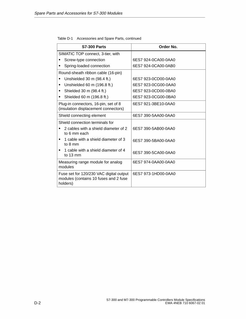
Spare Parts and Accessories for S7-300 Modules
D-2S7-300 and M7-300 Programmable Controllers Module Specifications
EWA 4NEB 710 6067-02 01
Table D-1 Accessories and Spare Parts, continued
S7-300 Parts Order No.
SIMATIC TOP connect, 3-tier, with
Screw-type connection
Spring-loaded connection
6ES7 924-0CA00-0AA0
6ES7 924-0CA00-0AB0
Round-sheath ribbon cable (16-pin)
Unshielded 30 m (98.4 ft.)
Unshielded 60 m (196.8 ft.)
Shielded 30 m (98.4 ft.)
Shielded 60 m (196.8 ft.)
6ES7 923-0CD00-0AA0
6ES7 923-0CG00-0AA0
6ES7 923-0CD00-0BA0
6ES7 923-0CG00-0BA0
Plug-in connectors, 16-pin, set of 8(insulation displacement connectors)
6ES7 921-3BE10-0AA0
Shield connecting element 6ES7 390-5AA00-0AA0
Shield connection terminals for
2 cables with a shield diameter of 2to 6 mm each
1 cable with a shield diameter of 3to 8 mm
1 cable with a shield diameter of 4to 13 mm
6ES7 390-5AB00-0AA0
6ES7 390-5BA00-0AA0
6ES7 390-5CA00-0AA0
Measuring range module for analogmodules
6ES7 974-0AA00-0AA0
Fuse set for 120/230 VAC digital outputmodules (contains 10 fuses and 2 fuseholders)
6ES7 973-1HD00-0AA0
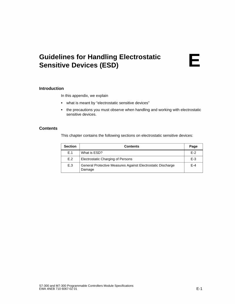
E-1S7-300 and M7-300 Programmable Controllers Module SpecificationsEWA 4NEB 710 6067-02 01
Guidelines for Handling ElectrostaticSensitive Devices (ESD)
Introduction
In this appendix, we explain
what is meant by “electrostatic sensitive devices”
the precautions you must observe when handling and working with electrostaticsensitive devices.
Contents
This chapter contains the following sections on electrostatic sensitive devices:
Section Contents Page
E.1 What is ESD? E-2
E.2 Electrostatic Charging of Persons E-3
E.3 General Protective Measures Against Electrostatic DischargeDamage
E-4
E
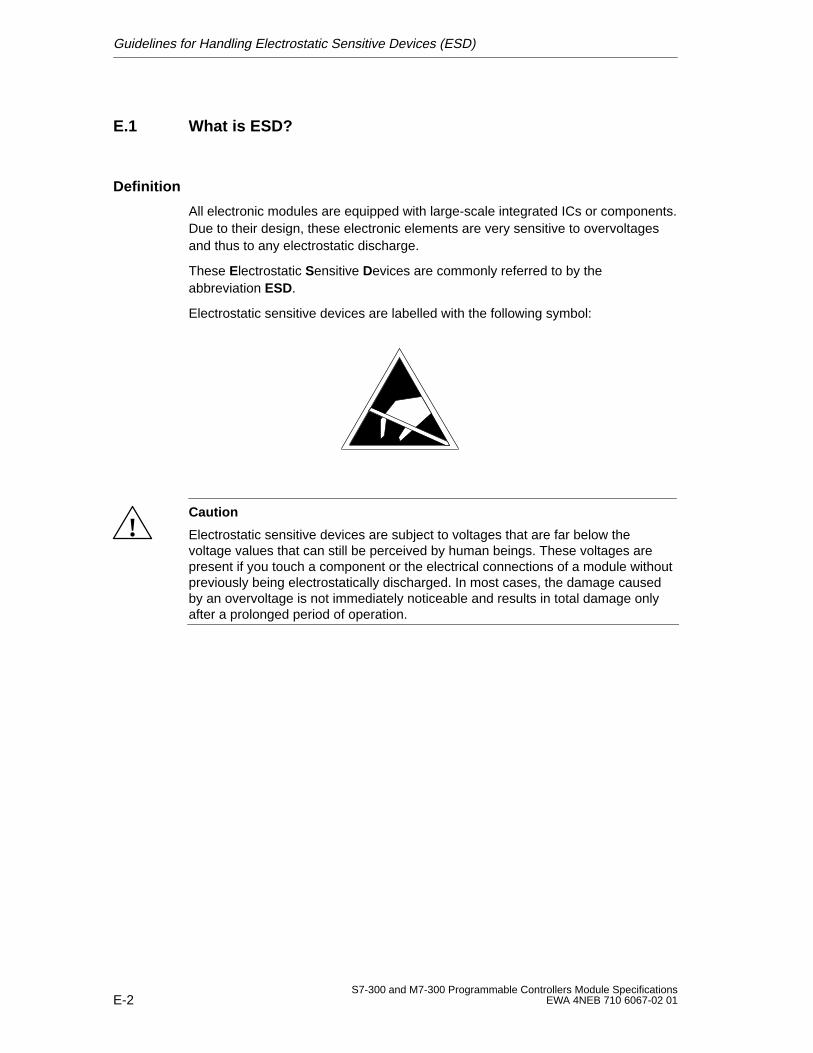
Guidelines for Handling Electrostatic Sensitive Devices (ESD)
E-2S7-300 and M7-300 Programmable Controllers Module Specifications
EWA 4NEB 710 6067-02 01
E.1 What is ESD?
Definition
All electronic modules are equipped with large-scale integrated ICs or components.Due to their design, these electronic elements are very sensitive to overvoltagesand thus to any electrostatic discharge.
These Electrostatic Sensitive Devices are commonly referred to by theabbreviation ESD.
Electrostatic sensitive devices are labelled with the following symbol:
!Caution
Electrostatic sensitive devices are subject to voltages that are far below thevoltage values that can still be perceived by human beings. These voltages arepresent if you touch a component or the electrical connections of a module withoutpreviously being electrostatically discharged. In most cases, the damage causedby an overvoltage is not immediately noticeable and results in total damage onlyafter a prolonged period of operation.
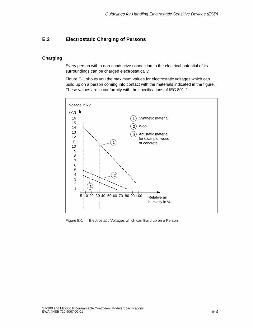
Guidelines for Handling Electrostatic Sensitive Devices (ESD)
E-3S7-300 and M7-300 Programmable Controllers Module SpecificationsEWA 4NEB 710 6067-02 01
E.2 Electrostatic Charging of Persons
Charging
Every person with a non-conductive connection to the electrical potential of itssurroundings can be charged electrostatically.
Figure E-1 shows you the maximum values for electrostatic voltages which canbuild up on a person coming into contact with the materials indicated in the figure.These values are in conformity with the specifications of IEC 801-2.
Voltage in kV
123456789
10111213141516
(kV)
5 10 20 30 40 50 60 70 80 90 100 Relative airhumidity in %
1
3
1 Synthetic material
2 Wool
3 Antistatic material, for example, wood or concrete
2
Figure E-1 Electrostatic Voltages which can Build up on a Person
Guidelines for Handling Electrostatic Sensitive Devices (ESD)
E-4S7-300 and M7-300 Programmable Controllers Module Specifications
EWA 4NEB 710 6067-02 01
E.3 General Protective Measures Against Electrostatic DischargeDamage
Ensure Sufficient Grounding
Make sure that the personnel, working surfaces and packaging are sufficientlygrounded when handling electrostatic sensitive devices. You thus avoidelectrostatic charging.
Avoid Direct Contact
You should touch electrostatic sensitive devices only if it is unavoidable(for example, during maintenance work). Hold modules without touching the pins ofcomponents or printed conductors. In this way, the discharged energy cannotaffect the sensitive devices.
If you have to carry out measurements on a module, you must discharge yourbody before you start the measurement by touching grounded metallic parts. Usegrounded measuring devices only.

F-1S7-300 and M7-300 Programmable Controllers Module SpecificationsEWA 4NEB 710 6067-02 01
List of Abbreviations
Abbreviation Description
ADC Analog-digital converter
AI Analog input
AO Analog output
CPU Central processing unit of programmable controller
DAC Digital-analog converter
DB Data block
DI Digital input
DO Digital output
EMC Electromagnetic compatibility
ESD Electrostatic sensitive device
FB Function block
IM Interface module
IP Intelligent I/O
LS Leading sign
M Ground connection
MPI Multiple point interface
OB Organization block
OP Operator panel
PG Programming device
PLC Programmable controller
PS Power supply
SFC System function
F

List of Abbreviations
F-2S7-300 and M7-300 Programmable Controllers Module Specifications
EWA 4NEB 710 6067-02 01
Glossary-1S7-300 and M7-300 Programmable Controllers Module SpecificationsEWA 4NEB 710 6067-02 01
Glossary
Analog ModuleAnalog modules convert analog process variables (for example, temperature)into digital values that can be processed in the CPU or they convert digital valuesinto analog manipulated variables.
Chassis GroundThe chassis ground comprises all interconnected inactive parts of an apparatus,which even in case of a fault cannot take dangerous touch voltages.
CPUCentral processing unit of the S7 programmable controller with control and arith-metic unit, memory, operating system and interface for programming device.
Data BlockData blocks (DB) are data areas in the user program, which contain user data.Global data blocks can be accessed by all code blocks and instance data blocksare assigned to a specific FB call.
Diagnostics System Diagnostics
Diagnostics BufferThe diagnostics buffer is a backed up memory area in the CPU where diagnosticevents are stored in the order they occur.
Diagnostics InterruptModules with diagnostics capability signal system errors to the CPU by meansof diagnostic interrupts.
Glossary
Glossary-2S7-300 and M7-300 Programmable Controllers Module Specifications
EWA 4NEB 710 6067-02 01
Equipotential BondingAn electrical connection (equipotential bonding conductor) that ties the exposedconductive parts of an item of electrical equipment and extraneous conductiveparts to the same, or approximately the same, potential in order to prevent dis-turbing or dangerous voltages between these parts.
Error DisplayError display is one of the possible responses of the operating system to a Run Time Error. The other possible responses include: Error Response in theuser program, STOP mode of the CPU.
Error Handling via OBWhen the operating system detects an error (for example, STEP 7 access error),it calls the specific organization block (error OB) for this error, where the furtherresponse of the CPU can be specified.
Functional GroundingGrounding whose only purpose is to ensure the intended function of the electricalequipment concerned. Functional grounding short-circuits any noise that mightotherwise have a detrimental effect on the equipment.
GroundThe conductive mass of the ground whose potential can be assumed to be zeroat any point.In the vicinity of ground electrodes, the ground may have a potential other thanzero. The term ”reference ground” is often used in this situation.
Ground (verb)To ground means connecting an electrically conductive part via a grounding sys-tem to ground (one or several electrically conductive parts that have good con-tact with the soil).
Hardware InterruptInterrupt-triggering modules trigger a hardware interrupt in the case of a certainevent in the process. The hardware interrupt is signalled to the CPU. In accor-dance with the priority of this interrupt, the corresponding Organization Blockis then executed.
Glossary
Glossary-3S7-300 and M7-300 Programmable Controllers Module SpecificationsEWA 4NEB 710 6067-02 01
InterruptThe Operating System of the CPU has 10 different priority classes whichcontrol execution of the user program. These priority classes include interrupts,as for example, process interrupts. When an interrupt occurs, the operating sys-tem automatically calls a corresponding organization block where the user canprogram the reaction desired (for example, in an FB).
Interrupt, Diagnostics Diagnostics Interrupt
Interrupt, Hardware Hardware Interrupt
IsolatedIn the case of isolated input/output modules, the reference potentials of the con-trol and load circuits are galvanically isolated from each other, for example, byoptocouplers, relay contacts or transformers. The input/output circuits can beconnected to a common potential.
Measuring Range ModuleMeasuring range modules are plugged onto the analog input module for adapta-tion to various measuring ranges.
Module ParametersModule parameters are used to set the module reactions. A difference is madebetween static and dynamic module parameters.
Non-IsolatedIn the case of non-isolated input/output modules, the reference potentials of thecontrol and load circuits are electrically connected to each other.
Operating ModeThe SIMATIC S7 programmable controllers have the following operating modes:STOP, RESTART, RUN.
Parameters1. Variable of a STEP 7 code block2. Variable for setting the module reaction (one or several per module). Eachmodule is supplied with a basic setting that can be changed by means of STEP7.Parameters can be Dynamic or Static.
Glossary
Glossary-4S7-300 and M7-300 Programmable Controllers Module Specifications
EWA 4NEB 710 6067-02 01
Parameters, DynamicIn contrast to static parameters, dynamic parameters of modules can bechanged during running operation by calling an SFC in the user program, for ex-ample, limit values of an analog signal input module.
Parameters, StaticIn contrast to dynamic parameters, static parameters of modules cannot bechanged by means of the user program, but only via STEP7, for example, inputdelay of a digital signal input module.
PG Programming Device
PLC Programmable Controller
Programmable ControllerProgrammable controllers (PLCs) are electronic control devices whose functionsare stored in the controller in the form of a program. The configuration and wiringof a PLC therefore do not depend on the actual functions of the control. Pro-grammable controllers and computers have similar structures: they consist of aCPU (central processing unit) with memory, input/output modules and an internalbus system. The I/O and programming language are tailored to the requirementsof open-loop control technology.
Programming DeviceProgramming devices are principally personal computers that are industry-stan-dard, compact and transportable. They are characterized by a special hardwareand software for SIMATIC programmable controllers.
Reference Ground Ground
Reference PotentialThe potential on which the voltages of the various circuits are based and accord-ing to which they are measured.
Glossary
Glossary-5S7-300 and M7-300 Programmable Controllers Module SpecificationsEWA 4NEB 710 6067-02 01
RESTARTOn transition from the STOP to the RUN mode, the PLC goes through the RE-START mode.It can be triggered using the Mode Selector or after a power on or throughoperator intervention on the programming device. With the S7-300, a Com-plete Restart is carried out.
S7-300 Backplane BusThe S7-300 backplane bus is a serial data bus the modules use to communicatewith each other and from which they draw the power they require. The connec-tion between the modules is implemented via bus connectors.
SFCSystem Function
Signal ModuleSignal modules (SMs) are the interface between the process and the program-mable controller. Signal modules comprise digital input and output modules (in-put/output module, digital) and analog input and output modules (input/outputmodule, analog).
STEP 7Programming language for generating user programs for SIMATIC S7 program-mable controllers.
Substitute ValueSubstitute values are values which are output to the process in the case of faultysignal output modules or which are used in the user program instead of a pro-cess variable in the case of faulty signal input modules. The substitute valuescan be specified in advance by the user (for example, maintain old value).
System DiagnosticsSystem diagnostics comprises the recognition, evaluation and signalling of errorswhich occur within the programmable controller. Examples of such errors include:Program errors or module failures. System errors can be indicated via LEDs orvia the STEP 7 tool S7 Information.
System FunctionA system function (SFC) is a Function integrated in the operating system ofthe CPU, which can be called in the STEP 7 user program if required.
Glossary
Glossary-6S7-300 and M7-300 Programmable Controllers Module Specifications
EWA 4NEB 710 6067-02 01
Total CurrentSum of currents of all output channels of a digital output module.
UngroundedWithout galvanic connection to ground
User ProgramWith SIMATIC; a difference is made between the Operating System of theCPU and user programs. The latter are generated by means of the STEP 7programming software in the possible programming languages (Ladder Logicand Statement List) and are stored in code blocks. Data is stored in data blocks.
Index-1S7-300 and M7-300 Programmable Controllers Module SpecificationsEWA 4NEB 710 6067-02 01
Index
AAccessories, D-1Actuators, connection to analog outputs, 4-34Addressing, analog input/output module SM
334, 4-113Active bus module, dimension drawing, C-8Ambient conditions, mechanical, 1-8Analog input
connecting sensor, 4-20measuring ranges, 4-4
Analog input channelmeasuring method, 4-43measuring range, 4-43
Analog input modulediagnostics, A-7diagnostics interrupt enable, A-7limit value, A-7limit value interrupt enable, A-7measurement (type), A-7parameters, A-7range, A-7reset time, A-7wire break, A-7
Analog input module SM 331; AI 2, 4-79channel groups, 4-84characteristics, 4-80current measurement, 4-88default setting, 4-84measured value resolution, 4-80measuring methods, 4-87measuring range module, 4-85measuring ranges, 4-87parameter assignment, 4-85resistance measurement, 4-84, 4-89start-up, 4-84technical specifications, 4-80temperature measurement, 4-89terminal connection diagram, 4-81voltage measurement, 4-88
Analog module, Glossary-1dependencies, 4-56diagnostics, 4-51diagnostics interrupt, 4-55dimension drawing, C-17parameters, 4-47process interrupt, 4-55
Analog outputconnecting loads/actuators, 4-34output ranges, 4-16
Analog output channelconversion time, 4-41response time, 4-42settling time, 4-42
Analog output modulediagnostics, A-11diagnostics interrupt enable, A-11output (range), A-11output (type), A-11substitute value, A-11
Index
Index-2S7-300 and M7-300 Programmable Controllers Module Specifications
EWA 4NEB 710 6067-02 01
Analog output module SM 332; AO 2, 4-96characteristics, 4-97current (output), 4-102default settings, 4-101output range, 4-102short-circuit check, 4-102start-up, 4-101technical specifications, 4-97terminal connection diagram, 4-98voltage (output), 4-102wire-break check, 4-102
Analog output modules, parameters, A-11Analog signal, cables for, 4-19, 4-34Analog value
conversion, 4-2resolution, 4-3sign, 4-3
Analog value representation, 4-2Analog-to-digital conversion, 4-40Analog output module SM 332; AO 4, 4-90
characteristics, 4-90current (output), 4-95default settings, 4-94substitute values, 4-96, 4-103output ranges, 4-95parameter assignment, 4-94, 4-101short-circuit check, 4-95start-up, 4-94technical specifications, 4-90terminal connection diagram, 4-91voltage (output), 4-95wire-break check, 4-95
Analog output channel, diagnostics byte, B-5Analog input/output module SM 334, 4-109,
4-115addressing, 4-113characteristics, 4-109diagnostics, 4-54electrical design, 4-113measuring method, 4-113output type, 4-113parameters, 4-50start-up, 4-113technical specifications, 4-109terminal connection diagram, 4-110
Analog input modulebasic settings, 4-49common-mode error, 4-52configuring error, 4-52diagnostics, 4-49, 4-52diagnostics interrupt enable, 4-49wire break, 4-53, 4-54wire-break check, 4-49error causes, 4-52limit value, 4-49isolated, 4-19limit interrupt enable, 4-49load voltage missing, 4-52measuring range overflow, 4-53measuring range underflow, 4-53measurement type, 4-49measuring range, 4-49measurement, 4-49non-isolated, 4-19parameters, 4-49parameter assignment error, 4-52group diagnostics, 4-49interference frequency suppression, 4-49
Analog input module SM 331; AI 8, 4-59terminal connection diagram, 4-61channel groups, 4-64characteristics, 4-60current measurement, 4-68default setting, 4-64wire-break check, 4-67, 4-87measured value resolution, 4-60measuring method, 4-67measuring range module, 4-66measuring ranges, 4-67parameter assignment, 4-66resistance measurement, 4-65, 4-69start-up, 4-64technical specifications, 4-60temperature measurement, 4-69voltage measurement, 4-68
Analog input channel, diagnostics byte, B-5Tightening torque, SIMATIC TOP connect, 8-9
Index
Index-3S7-300 and M7-300 Programmable Controllers Module SpecificationsEWA 4NEB 710 6067-02 01
Outputanalog output module, 4-50current (SM 332; AO 2), 4-102current (SM 332; AO 4), 4-95voltage (SM 332; AO 2), 4-102voltage (SM 332; AO 4), 4-95
Analog output moduleoutput type, 4-50configuring error, 4-54conversion time, 4-42cycle time, 4-41diagnostics, 4-50, 4-53diagnostics interrupt enable, 4-50error causes, 4-54isolated, 4-34load voltage missing, 4-54M short circuit, 4-54non-isolated, 4-34output, 4-50output range, 4-50parameters, 4-50parameter assignment error, 4-54group diagnostics, 4-50response with CPU-STOP, 4-50
Output type, analog output module, 4-50Output range
analog output module SM 332; AO 2, 4-102analog output module, 4-50of the analog outputs, 4-16SM 334, 4-17
Auxiliary power missingSM 321; DI 16 x 24VDC with process and
diagnostics interrupts, 3-16SM 322; DO 8 x 24VDC with diagnostics
interrupt, 3-45
BBackup battery, transport and storage
conditions, 1-6Basic settings, analog input module, 4-49Module types, code, B-2
CCable, for analog signals, 4-19, 4-34CE, marking, 1-2Channel groups
analog input module SM 331; AI 2, 4-84analog input module SM 331; AI 8, 4-64
Common-mode error, analog input module,4-52
Compensating box, 4-28Compensating leads, 4-27Configuring error
analog input module, 4-52analog output module, 4-54
Connecting cables, 8-3for SIMATIC TOP connect, 8-11
Connection notes, SIMATIC TOP connect,8-15
Connection to analog output, loads/actuators,4-34
Conversion timeanalog input channel, 4-39analog output channel, 4-41
Converting, analog values, 4-2CSA, 1-3Current (output)
analog output module SM 332; AO 2, 4-102analog output module SM 332; AO 4, 4-95
Current measurementanalog input module SM 331; AI 2, 4-88analog input module SM 331; AI 8, 4-68
Cycle timeanalog input module, 4-40analog output module, 4-41
DData records, for parameters, A-2Default setting
analog output module SM 332; AO 2, 4-101analog output module SM 332; AO 4, 4-94SM 322; DO 8 x 24VDC with diagnostics
interrupt, 3-42Default settings, SM 321; DI 16 x 24VDC with
process and diagnostics interrupt, 3-12Degree of protection, IP 20, 1-10Design, electrical, analog input/output module
SM 334, 4-113
Index
Index-4S7-300 and M7-300 Programmable Controllers Module Specifications
EWA 4NEB 710 6067-02 01
Diagnosticsanalog input/output module, 4-54analog output module, 4-50, 4-53analog input module, 4-49, 4-52channel-specific, B-4of the analog modules, 4-51parameter block, 4-52, 4-53SM 321; DI 16 x 24VDC with process and
diagnostics interrupts, 3-13, 3-15SM 322; DO 8 x 24VDC with diagnostics
interrupt, 3-44Diagnostics interrupt enable
analog input module, 4-49analog output module, 4-50SM 321; DI 16 x 24VDC with process and
diagnostics interrupts, 3-13SM 322; DO 8 x 24VDC with diagnostics
interrupt, 3-43Digital output channel, diagnostics byte, B-6Diagnostics byte
analog output channel, B-5analog input channel, B-5digital output channel, B-6digital input channel, B-6
Diagnostics data, B-1Diagnostics
analog input module, A-7analog output module, A-11digital input module, A-3digital output module, A-5system, Glossary-5
Diagnostics buffer, Glossary-1Diagnostics entry, 4-59Diagnostics interrupt, 3-17, 3-46, 4-59,
Glossary-1analog module, 4-55
Diagnostics interrupt enableanalog input module, A-7analog output module, A-11digital input module, A-3digital output module, A-5
Digital input module, 3-2diagnostics, A-3diagnostics interrupt enable, A-3input delay, A-3process interrupt, A-3process interrupt enable, A-3
Digital input modules, parameters, A-3Digital input/output module, 3-70Digital module, dimension drawing, C-17Digital modules, 3-1
Digital output moduleSee also SM 322diagnostics, A-5diagnostics interrupt enable, A-5hold last value, A-5parameters, A-5substitute value, A-5substitute value enable, A-5
Digital input channel, diagnostics byte, B-6Dimension drawings, C-1
analog module, C-17digital module, C-17IM 360, C-14IM 365, C-16interface module, C-14power supply module PS 307, C-9PS 307, C-9rail, C-2RS 485 repeater, C-20shield connecting element, C-18signal module, C-17SIMATIC TOP connect, C-19
Wire break, SM 322; DO 8 x 24VDC withdiagnostics interrupt, 3-43, 3-45
Wire-break checkanalog output module SM 332; AO 2, 4-102analog output module SM 332; AO 4, 4-95analog input module, 4-49analog input module SM 331; AI 8, 4-67,
4-87Dummy module, 5-4
EInput delay, SM 321; DI 16 x 24VDC with
process and diagnostics interrupts, 3-13,3-14
Electromagnetic compatibility, 1-4EMC directive, 1-3Environmental conditions, 1-7EPROM error
SM 321; DI 16 x 24VDC with process anddiagnostics interrupts, 3-16
SM 322; DO 8 x 24VDC with diagnosticsinterrupt, 3-45
Index
Index-5S7-300 and M7-300 Programmable Controllers Module SpecificationsEWA 4NEB 710 6067-02 01
Error causesanalog input module, 4-52analog output module, 4-54SM 321; DI 16 x 24VDC with process and
diagnostics interrupts, 3-16SM 322; DO 8 x 24VDC with diagnostics
interrupt, 3-45Error display, Glossary-2Substitute value, SM 322; DO 8 x 24VDC with
diagnostics interrupt, 3-43Substitute a value, SM 322; DO 8 x 24VDC
with diagnostics interrupt, 3-43Substitute values, analog output module SM
332; AO 4, 4-96, 4-103
FMissing load voltage, SM 322; DO 8 x 24VDC
with diagnostics interrupt, 3-43FM, approval, 1-3Four-wire transducer, 4-19
analog input module SM 331; AI 8, 4-68connection, 4-32measuring ranges, 4-88
Front connector module, with flat ribbonconnection, 8-3
Fuse blownSM 321; DI 16 x 24VDC with process and
diagnostics interrupts, 3-16SM 322; DO 8 x 24VDC with diagnostics
interrupt, 3-45
GLimit value, analog input module, 4-49Grounded operation, RS 485 repeater, 7-4
HHardware interrupt, Glossary-2Hold last value, digital output module, A-5
IIEC 1131, 1-2IM 360
dimension drawing, C-14interface module, 6-2
IM 361, interface module, 6-4
IM 365dimension drawing, C-16interface module, 6-6
Input delay, digital input module, A-3Interface module, 6-1
dimension drawing, C-14IM 360, 6-2IM 361, 6-4IM 365, 6-6
Interferencepulse-shaped, 1-4sinusoidal, 1-5
Internal compensation, 4-27Interrupt, Glossary-3IP 20, 1-10
KChannel-specific errors, B-4Compensation
external, 4-28internal, 4-27, 4-28
Short circuit to L+, SM 322; DO 8 x 24VDCwith diagnostics interrupt, 3-43
Short circuit to M, SM 322; DO 8 x 24VDC withdiagnostics interrupt, 3-43, 3-45
LConductors, number, 8-9Conductors (SIMATIC TOP connect), length of
insulation to be stripped, 8-9Connecting conductors, tightening torque, 8-9Conductor cross-sectional areas, 8-9Hold last value, SM 322; DO 8 x 24VDC with
diagnostics interrupt, 3-43Limit interrupt enable, analog input module,
4-49Limit value, analog input module, A-7Limit value interrupt enable, analog input
module, A-7Load voltage missing
analog input module, 4-52analog output module, 4-54SM 322; DO 8 x 24VDC with diagnostics
interrupt, 3-45Loads, connection to analog outputs, 4-34
Index
Index-6S7-300 and M7-300 Programmable Controllers Module Specifications
EWA 4NEB 710 6067-02 01
MM short circuit, analog output module, 4-54Dimension drawing, active bus module, C-8Measured value resolution, 4-4Measured value tables, for analog inputs, 4-4Measurement, analog input module, A-7Measurement (type), analog input module, A-7Measuring method
analog input channels, 4-43analog input module SM 331; AI 2, 4-87analog input module SM 331; AI 8, 4-67analog input/output module SM 334, 4-113
Measuring range module, 4-43, Glossary-3analog input module SM 331; AI 2, 4-85analog input module SM 331; AI 8, 4-66
Measuring range overflow, analog inputmodule, 4-53
Measuring range underflow, analog inputmodule, 4-53
Measurement type, analog input module, 4-49Measuring range, 4-2
analog input channels, 4-43analog input module SM 331; AI 2, 4-87analog input module SM 331; AI 8, 4-67analog input module, 4-49of the analog inputs, 4-4SM 334, 4-15
Measurement, analog input module, 4-49Module, transport and storage conditions, 1-6Module parameters, Glossary-3
NStandards, 1-2
OOperating conditions, 1-7Output (range), 4-2
analog output module, A-11analog output module SM 332; AO 4, 4-95
Output (type)analog input/output module SM 334, 4-113analog output module, A-11
PParameters
analog input/output module, 4-50analog module, 4-47analog output module, 4-50analog input module, 4-49
Parameter assignment erroranalog input module, 4-52analog output module, 4-54
Parameter block, diagnostics, 4-52, 4-53Parameter sets, for signal modules, A-1Parameters, Glossary-3
analog input module, A-7analog output modules, A-11data records, A-2digital input modules, A-3digital output module, A-5modules, Glossary-3SM 321; DI 16 x 24VDC with process and
diagnostics interrupts, 3-13SM 322; DO 8 x 24VDC with diagnostics
interrupt, 3-43Parameters, incorrect, SM 321; DI 16 x 24VDC
with process and diagnostics interrupts,3-16
Parameter assignmentanalog output module SM 332; AO 4, 4-94,
4-101SM 321; DI 16 x 24VDC with process and
diagnostics interrupts, 3-13SM 322; DO 8 x 24VDC with diagnostics
interrupt, 3-42PARM_MOD, SFC 57, A-2Power supply module, 2-1
dimension drawing, C-9Process interrupt
analog module, 4-55digital input module, A-3
Process interrupt enable, digital input module,A-3
Process interrupt lostSM 321; DI 16 x 24VDC with process and
diagnostics interrupt, 3-17SM 321; DI 16 x 24VDC with process and
diagnostics interrupts, 3-16
Index
Index-7S7-300 and M7-300 Programmable Controllers Module SpecificationsEWA 4NEB 710 6067-02 01
Process interrupt, 3-17SM 321; DI 16 x 24VDC with process and
diagnostics interrupts, 3-13Process interrupt enable, SM 321; DI 16 x
24VDC with process and diagnosticsinterrupts, 3-13
PS 307, dimension drawing, C-9Pulse-shaped interference, 1-4
RRadio interference, emission of, 1-5Rail for the ”Insert and Remove” function,
dimension drawing, C-7Rails, dimension drawing, C-2RAM error
SM 321; DI 16 x 24VDC with process anddiagnostics interrupts, 3-16
SM 322; DO 8 x 24VDC with diagnosticsinterrupt, 3-45
Rated voltage, 1-11Reference junction, for thermocouple, 4-27Relay output module, 3-59Repeater. See RS 485 repeaterReset time, analog input module, A-7Resistance measurement, 4-89
analog input module SM 331; AI 2, 4-84,4-89
analog input module SM 331; AI 8, 4-65,4-69
Resistance-type thermometer, connection,4-33
Resolution, analog value, 4-3Response time, 4-42RS 485 repeater, 7-1
application, 7-2block diagram, 7-7definition, 7-2design, 7-3dimension drawing, C-20galvanic isolation, 7-4grounded operation, 7-4pin assignment of the PG/OP socket, 7-6rules, 7-2technical specifications, 7-5
Rules for wiring, SIMATIC TOP connect, 8-9
SGroup diagnostics
analog output module, 4-50analog input module, 4-49
Sensorconnecting, 4-19isolated, 4-21non-isolated, 4-23to analog inputs, 4-20
Sensor supply missing, SM 321; DI 16 x24VDC with process and diagnosticsinterrupts, 3-16
Settling time, 4-42SFC 55 WR_PARM, A-2SFC 56 WR_DPARM, A-2SFC 57 PARM_MOD, A-2Shield connecting element, dimension drawing,
C-18Short circuit to P, SM 322; DO 8 x 24VDC with
diagnostics interrupt, 3-45Short-circuit check
analog output module SM 332; AO 2, 4-102analog output module SM 332; AO 4, 4-95
Sign, analog value, 4-3Signal module, Glossary-5
dimension drawing, C-17parameter sets, A-1
SIMATIC TOP connect, 8-1, 9-1application areas, 8-2components, 8-2connecting cables, 8-11connection notes, 8-15dimension drawing, C-19rules for wiring, 8-9selection, 8-6spring-loaded connections, 8-10terminal assignments. See Terminal blockwiring the front connector, 8-13wiring the terminal block, 8-13
Simulator module, 5-2Sinusoidal interference, 1-5SM 321; DI 16 x 120VAC
characteristics, 3-22technical data, 3-24terminal connection diagram, 3-23
Index
Index-8S7-300 and M7-300 Programmable Controllers Module Specifications
EWA 4NEB 710 6067-02 01
SM 321; DI 16 x 24VDCcharacteristics, 3-6technical data, 3-8Terminal connection diagram, 3-7
SM 321; DI 16 x 24VDC with process anddiagnostics interruptcharacteristics, 3-9diagnostics interrupt, 3-17process interrupt, 3-17process interrupt lost, 3-17redundant sensor supply, 3-10setting the parameters, 3-12technical data, 3-11terminal connection diagram, 3-10
SM 321; DI 16 x 24VDC with process anddiagnostics interruptsauxiliary power missing, 3-16default setting, 3-13diagnostics interrupt enable, 3-13diagnostics, 3-13, 3-15EPROM error, 3-16error causes, 3-16fuse blown, 3-16input delay, 3-14parameters, 3-13parameters, incorrect, 3-16parameter assignment, 3-13process interrupt lost, 3-16process interrupt, 3-13process interrupt enable, 3-13RAM error, 3-16sensor supply missing, 3-16watchdog, 3-16
SM 321; DI 16 x 24VDC; source inputcharacteristics, 3-19technical data, 3-21terminal connection diagram, 3-20
SM 321; DI 16 x 24VDC with process anddiagnostics interrupts, input delay, 3-13
SM 321; DI 32 x 24VDCcharacteristics, 3-2technical data, 3-5terminal connection diagram, 3-3
SM 321; DI 8 x 120/230VACcharacteristics, 3-25technical data, 3-27terminal connection diagram, 3-26
SM 322, 3-31SM 322; DO 16 x 120VAC
characteristics, 3-50technical data, 3-52terminal connection diagram, 3-51
SM 322; DO 16 x 230VAC REL.characteristics, 3-59technical data, 3-61terminal connection diagram, 3-60
SM 322; DO 16 x 24VDCcharacteristics, 3-35technical data, 3-37terminal connection diagram, 3-36
SM 322; DO 32 x 24VDCcharacteristics, 3-31technical data, 3-34terminal connection diagram, 3-32
SM 322; DO 8 x 120/230VACcharacteristics, 3-53technical data, 3-55terminal connection diagram, 3-54
SM 322; DO 8 x 230VAC REL.characteristics, 3-62technical data, 3-64terminal connection diagram, 3-63
Index
Index-9S7-300 and M7-300 Programmable Controllers Module SpecificationsEWA 4NEB 710 6067-02 01
SM 322; DO 8 x 24VDCcharacteristics, 3-47technical data, 3-49terminal connection diagram, 3-48
SM 322; DO 8 x 24VDC with diagnosticsinterruptauxiliary power missing, 3-45characteristics, 3-38default setting, 3-42diagnostics interrupt enable, 3-43diagnostics, 3-44diagnostics interrupt, 3-46wire break, 3-43, 3-45EPROM error, 3-45error causes, 3-45substitute value, 3-43substitute a value, 3-43missing load voltage, 3-43fuse blown, 3-45short circuit to L+, 3-43short circuit to M, 3-43, 3-45hold last value, 3-43load voltage missing, 3-45output signals, redundant, 3-40parameters, 3-43parameter assignment, 3-42RAM error, 3-45redundant output signals, 3-40setting the parameters, 3-42short circuit to P, 3-45technical data, 3-41terminal connection diagram, 3-39response with CPU-STOP, 3-43watchdog, 3-45
SM 322; DO 8 x Rel. 230VACcharacteristics, 3-66technical specifications, 3-68terminal connection diagram, 3-67
SM 323; DI/DO 16 x 24VDCcharacteristics, 3-70technical data, 3-72, 3-76terminal connection diagram, 3-71
SM 323; DI/DO 8 x 24VDCcharacteristics, 3-74terminal connection diagram, 3-75
SM 338, POS input module, 5-7SM 338 POS input module, 5-7SM 374, simulator module, 5-2Spare parts, D-1Spring-loaded connections, SIMATIC TOP
connect, 8-10
Interference frequency suppression, analoginput module, 4-49
Substitute value, Glossary-5analog output module, A-11digital output module, A-5
Substitute value enable, digital output module,A-5
System diagnostics, Glossary-5System data area, diagnostics data, B-1
TTechnical specifications, RS 485 repeater, 7-5Temperature measurement
analog input module SM 331; AI 2, 4-89analog input module SM 331; AI 8, 4-69
Terminal block, 8-3terminal assignments, 8-7
Test voltages, 1-10Thermo resistance measurement, 4-69Thermocouple, 4-26
choice of connections, 4-29connecting, 4-28design, 4-26principle of operation, 4-26reference junction, 4-27types, 4-26with compensating box, 4-29without compensating box, 4-30
Transducer2-wire, 4-194-wire, 4-19connecting, 4-19
Two-wire transducer, 4-19analog input module SM 331; AI 8, 4-68connection, 4-32measuring ranges, 4-88
UUL, 1-3User program, Glossary-6
VResponse with CPU-STOP
analog output module, 4-50SM 322; DO 8 x 24VDC with diagnostics
interrupt, 3-43
Index
Index-10S7-300 and M7-300 Programmable Controllers Module Specifications
EWA 4NEB 710 6067-02 01
Vibrations, 1-9Voltage, rated, 1-11Voltage (output)
analog output module SM 332; AO 2, 4-102analog output module SM 332; AO 4, 4-95
Voltage measurementanalog input module SM 331; AI 2, 4-88analog input module SM 331; AI 8, 4-68
Voltage sensor, 4-19connection, 4-31
WWatchdog
SM 321; DI 16 x 24VDC with process anddiagnostics interrupts, 3-16
SM 322; DO 8 x 24VDC with diagnosticsinterrupt, 3-45
Wire break, analog input module, A-7Wiring the front connector, SIMATIC TOP
connect, 8-13Wiring the terminal block, SIMATIC TOP
connect, 8-13WR_DPARM, SFC 56, A-2WR_PARM, SFC 55, A-2
ZApprobations, 1-2

1S7-300 and M7-300 Programmable Controllers Module SpecificationsEWA 4NEB 710 6067-02 01
To
Siemens AG
A&D AS E 82
Postfach 1963
D–92209 Amberg
From
Your Name: _ _ _ _ _ _ _ _ _ _ _ _ _ _ _ _ _ _ _ _ _ _ _ _ _ _ _ _ _ _ _
Your Title: _ _ _ _ _ _ _ _ _ _ _ _ _ _ _ _ _ _ _ _ _ _ _ _ _ _ _ _ _ _
Company Name: _ _ _ _ _ _ _ _ _ _ _ _ _ _ _ _ _ _ _ _ _ _ _ _ _ _ _ _ _ _ _
Street: _ _ _ _ _ _ _ _ _ _ _ _ _ _ _ _ _ _ _ _ _ _ _ _ _ _ _ _ _ _ _
City, Zip Code: _ _ _ _ _ _ _ _ _ _ _ _ _ _ _ _ _ _ _ _ _ _ _ _ _ _ _ _ _
Country: _ _ _ _ _ _ _ _ _ _ _ _ _ _ _ _ _ _ _ _ _ _ _ _ _ _ _ _ _ _
Phone: _ _ _ _ _ _ _ _ _ _ _ _ _ _ _ _ _ _ _ _ _ _ _ _ _ _ _ _ _ _
Please check any industry that applies to you:
Automotive
Chemical
Electrical Machinery
Food
Instrument and Control
Nonelectrical Machinery
Petrochemical
Pharmaceutical
Plastic
Pulp and Paper
Textiles
Transportation
Other _ _ _ _ _ _ _ _ _ _ _ _ _

2S7-300 and M7-300 Programmable Controllers Module Specifications
EWA 4NEB 710 6067-02 01
Additional comments:
_ _ _ _ _ _ _ _ _ _ _ _ _ _ _ _ _ _ _ _ _ _ _ _ _ _ _ _ _ _ _ _ _ _ _ _ _ _ _ _
_ _ _ _ _ _ _ _ _ _ _ _ _ _ _ _ _ _ _ _ _ _ _ _ _ _ _ _ _ _ _ _ _ _ _ _ _ _ _ _
_ _ _ _ _ _ _ _ _ _ _ _ _ _ _ _ _ _ _ _ _ _ _ _ _ _ _ _ _ _ _ _ _ _ _ _ _ _ _ _
_ _ _ _ _ _ _ _ _ _ _ _ _ _ _ _ _ _ _ _ _ _ _ _ _ _ _ _ _ _ _ _ _ _ _ _ _ _ _ _
_ _ _ _ _ _ _ _ _ _ _ _ _ _ _ _ _ _ _ _ _ _ _ _ _ _ _ _ _ _ _ _ _ _ _ _ _ _ _ _
_ _ _ _ _ _ _ _ _ _ _ _ _ _ _ _ _ _ _ _ _ _ _ _ _ _ _ _ _ _ _ _ _ _ _ _ _ _ _ _
_ _ _ _ _ _ _ _ _ _ _ _ _ _ _ _ _ _ _ _ _ _ _ _ _ _ _ _ _ _ _ _ _ _ _ _ _ _ _ _
_ _ _ _ _ _ _ _ _ _ _ _ _ _ _ _ _ _ _ _ _ _ _ _ _ _ _ _ _ _ _ _ _ _ _ _ _ _ _ _
_ _ _ _ _ _ _ _ _ _ _ _ _ _ _ _ _ _ _ _ _ _ _ _ _ _ _ _ _ _ _ _ _ _ _ _ _ _ _ _
_ _ _ _ _ _ _ _ _ _ _ _ _ _ _ _ _ _ _ _ _ _ _ _ _ _ _ _ _ _ _ _ _ _ _ _ _ _ _ _
_ _ _ _ _ _ _ _ _ _ _ _ _ _ _ _ _ _ _ _ _ _ _ _ _ _ _ _ _ _ _ _ _ _ _ _ _ _ _ _
_ _ _ _ _ _ _ _ _ _ _ _ _ _ _ _ _ _ _ _ _ _ _ _ _ _ _ _ _ _ _ _ _ _ _ _ _ _ _ _
_ _ _ _ _ _ _ _ _ _ _ _ _ _ _ _ _ _ _ _ _ _ _ _ _ _ _ _ _ _ _ _ _ _ _ _ _ _ _ _
_ _ _ _ _ _ _ _ _ _ _ _ _ _ _ _ _ _ _ _ _ _ _ _ _ _ _ _ _ _ _ _ _ _ _ _ _ _ _ _
_ _ _ _ _ _ _ _ _ _ _ _ _ _ _ _ _ _ _ _ _ _ _ _ _ _ _ _ _ _ _ _ _ _ _ _ _ _ _ _
Please give each of the following questions your own personal mark within the range from 1 (verygood) to 5 (poor).
1. Do the contents meet your requirements?
2. Is the information you need easy to find?
3. Is the text easy to understand?
4. Does the level of technical detail meet your requirements?
5. Please rate the quality of the graphics/tables:
Remarks Form
Your comments and recommendations will help us to improve the quality and usefulness of ourpublications. Please take the first available opportunity to fill out this questionnaire and return itto Siemens.
1S7-300 and M7-300 Programmable Controllers Module SpecificationsEWA 4NEB 710 6067-02 01
To
Siemens AG
A&D AS E 82
Postfach 1963
D–92209 Amberg
From
Your Name: _ _ _ _ _ _ _ _ _ _ _ _ _ _ _ _ _ _ _ _ _ _ _ _ _ _ _ _ _ _ _
Your Title: _ _ _ _ _ _ _ _ _ _ _ _ _ _ _ _ _ _ _ _ _ _ _ _ _ _ _ _ _ _
Company Name: _ _ _ _ _ _ _ _ _ _ _ _ _ _ _ _ _ _ _ _ _ _ _ _ _ _ _ _ _ _ _
Street: _ _ _ _ _ _ _ _ _ _ _ _ _ _ _ _ _ _ _ _ _ _ _ _ _ _ _ _ _ _ _
City, Zip Code: _ _ _ _ _ _ _ _ _ _ _ _ _ _ _ _ _ _ _ _ _ _ _ _ _ _ _ _ _
Country: _ _ _ _ _ _ _ _ _ _ _ _ _ _ _ _ _ _ _ _ _ _ _ _ _ _ _ _ _ _
Phone: _ _ _ _ _ _ _ _ _ _ _ _ _ _ _ _ _ _ _ _ _ _ _ _ _ _ _ _ _ _
Please check any industry that applies to you:
Automotive
Chemical
Electrical Machinery
Food
Instrument and Control
Nonelectrical Machinery
Petrochemical
Pharmaceutical
Plastic
Pulp and Paper
Textiles
Transportation
Other _ _ _ _ _ _ _ _ _ _ _ _ _
2S7-300 and M7-300 Programmable Controllers Module Specifications
EWA 4NEB 710 6067-02 01
Additional comments:
_ _ _ _ _ _ _ _ _ _ _ _ _ _ _ _ _ _ _ _ _ _ _ _ _ _ _ _ _ _ _ _ _ _ _ _ _ _ _ _
_ _ _ _ _ _ _ _ _ _ _ _ _ _ _ _ _ _ _ _ _ _ _ _ _ _ _ _ _ _ _ _ _ _ _ _ _ _ _ _
_ _ _ _ _ _ _ _ _ _ _ _ _ _ _ _ _ _ _ _ _ _ _ _ _ _ _ _ _ _ _ _ _ _ _ _ _ _ _ _
_ _ _ _ _ _ _ _ _ _ _ _ _ _ _ _ _ _ _ _ _ _ _ _ _ _ _ _ _ _ _ _ _ _ _ _ _ _ _ _
_ _ _ _ _ _ _ _ _ _ _ _ _ _ _ _ _ _ _ _ _ _ _ _ _ _ _ _ _ _ _ _ _ _ _ _ _ _ _ _
_ _ _ _ _ _ _ _ _ _ _ _ _ _ _ _ _ _ _ _ _ _ _ _ _ _ _ _ _ _ _ _ _ _ _ _ _ _ _ _
_ _ _ _ _ _ _ _ _ _ _ _ _ _ _ _ _ _ _ _ _ _ _ _ _ _ _ _ _ _ _ _ _ _ _ _ _ _ _ _
_ _ _ _ _ _ _ _ _ _ _ _ _ _ _ _ _ _ _ _ _ _ _ _ _ _ _ _ _ _ _ _ _ _ _ _ _ _ _ _
_ _ _ _ _ _ _ _ _ _ _ _ _ _ _ _ _ _ _ _ _ _ _ _ _ _ _ _ _ _ _ _ _ _ _ _ _ _ _ _
_ _ _ _ _ _ _ _ _ _ _ _ _ _ _ _ _ _ _ _ _ _ _ _ _ _ _ _ _ _ _ _ _ _ _ _ _ _ _ _
_ _ _ _ _ _ _ _ _ _ _ _ _ _ _ _ _ _ _ _ _ _ _ _ _ _ _ _ _ _ _ _ _ _ _ _ _ _ _ _
_ _ _ _ _ _ _ _ _ _ _ _ _ _ _ _ _ _ _ _ _ _ _ _ _ _ _ _ _ _ _ _ _ _ _ _ _ _ _ _
_ _ _ _ _ _ _ _ _ _ _ _ _ _ _ _ _ _ _ _ _ _ _ _ _ _ _ _ _ _ _ _ _ _ _ _ _ _ _ _
_ _ _ _ _ _ _ _ _ _ _ _ _ _ _ _ _ _ _ _ _ _ _ _ _ _ _ _ _ _ _ _ _ _ _ _ _ _ _ _
_ _ _ _ _ _ _ _ _ _ _ _ _ _ _ _ _ _ _ _ _ _ _ _ _ _ _ _ _ _ _ _ _ _ _ _ _ _ _ _
Please give each of the following questions your own personal mark within the range from 1 (verygood) to 5 (poor).
1. Do the contents meet your requirements?
2. Is the information you need easy to find?
3. Is the text easy to understand?
4. Does the level of technical detail meet your requirements?
5. Please rate the quality of the graphics/tables:
Remarks Form
Your comments and recommendations will help us to improve the quality and usefulness of ourpublications. Please take the first available opportunity to fill out this questionnaire and return itto Siemens.