Embed Size (px)
Citation preview

Applications & Tools
Answers for industry.
Counting and Measuring with theCounter Module "TM Count 2x24V"S7-1500, ET 200MP, "TM Count 2x24V"
Application Description September 2013
Warranty and Liability
Counter Module TM CountV 1.0, Entry ID: 76798774 2
Cop
yrig
htSi
emen
sAG
2013
Allr
ight
sre
serv
ed
Warranty and Liability
Note The Application Examples are not binding and do not claim to be completeregarding the circuits shown, equipping and any eventuality. The ApplicationExamples do not represent customer-specific solutions. They are only intendedto provide support for typical applications. You are responsible for ensuring thatthe described products are used correctly. These Application Examples do notrelieve you of the responsibility to use sound practices in application, installation,operation and maintenance. When using these Application Examples, yourecognize that we cannot be made liable for any damage/claims beyond theliability clause described. We reserve the right to make changes to theseApplication Examples at any time without prior notice. If there are any deviationsbetween the recommendations provided in these Application Examples andother Siemens publications – e.g. Catalogs – the contents of the otherdocuments have priority.
We do not accept any liability for the information contained in this document.Any claims against us – based on whatever legal reason – resulting from the use ofthe examples, information, programs, engineering and performance data etc.,described in this Application Example shall be excluded. Such an exclusion shallnot apply in the case of mandatory liability, e.g. under the German Product LiabilityAct (“Produkthaftungsgesetz”), in case of intent, gross negligence, or injury of life,body or health, guarantee for the quality of a product, fraudulent concealment of adeficiency or breach of a condition which goes to the root of the contract(“wesentliche Vertragspflichten”). The damages for a breach of a substantialcontractual obligation are, however, limited to the foreseeable damage, typical forthe type of contract, except in the event of intent or gross negligence or injury tolife, body or health. The above provisions do not imply a change of the burden ofproof to your detriment.Any form of duplication or distribution of these Application Examples or excerptshereof is prohibited without the expressed consent of Siemens Industry Sector.
Siemens Industry Online SupportThis entry is taken from the Siemens Industry Online Support. The following linkwill take you directly to the download page of this document:http://support.automation.siemens.com/WW/view/en/76798774
Table of Contents
Counter Module TM CountV 1.0, Entry ID: 76798774 3
Cop
yrig
htSi
emen
sAG
2013
Allr
ight
sre
serv
ed
Table of ContentsWarranty and Liability ................................................................................................. 2
1 Task ..................................................................................................................... 4
2 Solution............................................................................................................... 6
2.1 Overview............................................................................................... 62.2 Hardware and software components ................................................... 92.2.1 Validity .................................................................................................. 92.2.2 Components used ................................................................................ 9
3 Function Principle: Scenario "Fill bottles" ................................................... 11
3.1 General overview ............................................................................... 113.2 Functions of the user program ........................................................... 133.3 The function block "Fill_bottles" (FB1) ............................................... 143.4 The function "ChangeMaxCountVal" (FC1) ....................................... 163.5 The function block "High_Speed_Counter" (FB1150) ........................ 18
4 Function Principle: Scenario "Bake cupcakes" ........................................... 19
4.1 General overview ............................................................................... 194.2 Functions of the user program ........................................................... 224.3 The function block "Conv_v_monitor" (FB1) ...................................... 234.4 The function block "Para_TM" (FB2) .................................................. 254.5 The function block "ChangeSpeedLimits" (FB3) ................................ 264.6 The instructions "RDREC" and "WRREC" ......................................... 28
5 Configuration and Settings of the Technology Module ............................... 29
5.1 Setting parameters with the technology object .................................. 305.1.1 Hardware configuration (HWCN) ....................................................... 305.1.2 Technology object .............................................................................. 325.2 Programming: The FB "High_Speed_Counter" (FB1150) ................. 365.2.1 Using the technology object ............................................................... 365.2.2 Further parameters FB "High_Speed_Counter" (FB 1150) ............... 365.3 Setting parameters using HWCN and the data record 128 ................ 385.3.1 Hardware configuration (HWCN) ....................................................... 385.3.2 The parameter data record 129 ......................................................... 435.4 Programming: The control and feedback interface ............................ 44
6 Installation ........................................................................................................ 45
6.1 Hardware installation .......................................................................... 456.2 Software installation ........................................................................... 466.3 Configuring the hardware ................................................................... 46
7 Operation of the Application .......................................................................... 49
7.1 Overview............................................................................................. 497.2 Operation via the WinCC Runtime ..................................................... 497.2.1 Scenario "Fill bottles" ......................................................................... 497.2.2 Scenario "Bake cupcakes" ................................................................. 527.3 Monitoring and controlling via the watch tables ................................. 54
8 References ....................................................................................................... 55
9 History............................................................................................................... 55
1 Task2.1 Overview
Counter Module TM CountV 1.0, Entry ID: 76798774 4
Cop
yrig
htSi
emen
sAG
2013
Allr
ight
sre
serv
ed
1 TaskIntroduction
The counter module "TM Count 2x24V" for S7-1500 and ET 200MP is used inparticular for capturing fast digital signals.The counter module can: count signals. capture frequencies and speeds. capture period durations.
Extensive parameter setting options allow to adapt the module optimally to therespective automation task. The module takes tasks off the control in this way.Two scenarios are used in the Application Example to demonstrate how thecounter module (the technology module) can be parameterized and used.
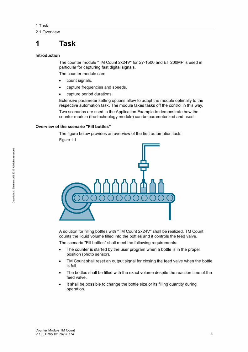
Overview of the scenario "Fill bottles"The figure below provides an overview of the first automation task:Figure 1-1
A solution for filling bottles with "TM Count 2x24V" shall be realized. TM Countcounts the liquid volume filled into the bottles and it controls the feed valve.The scenario "Fill bottles" shall meet the following requirements: The counter is started by the user program when a bottle is in the proper
position (photo sensor). TM Count shall reset an output signal for closing the feed valve when the bottle
is full. The bottles shall be filled with the exact volume despite the reaction time of the
feed valve. It shall be possible to change the bottle size or its filling quantity during
operation.
1 Task2.1 Overview
Counter Module TM CountV 1.0, Entry ID: 76798774 5
Cop
yrig
htSi
emen
sAG
2013
Allr
ight
sre
serv
ed
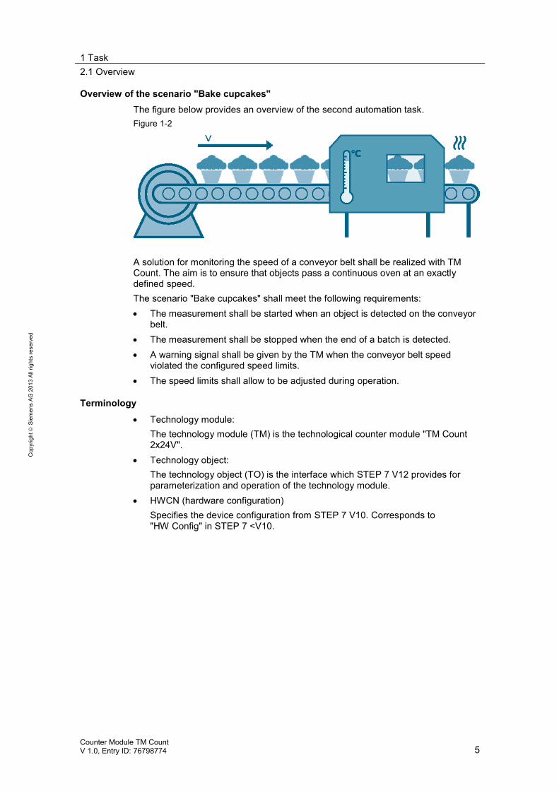
Overview of the scenario "Bake cupcakes"The figure below provides an overview of the second automation task.Figure 1-2
A solution for monitoring the speed of a conveyor belt shall be realized with TMCount. The aim is to ensure that objects pass a continuous oven at an exactlydefined speed.The scenario "Bake cupcakes" shall meet the following requirements: The measurement shall be started when an object is detected on the conveyor
belt. The measurement shall be stopped when the end of a batch is detected. A warning signal shall be given by the TM when the conveyor belt speed
violated the configured speed limits. The speed limits shall allow to be adjusted during operation.
Terminology
Technology module:The technology module (TM) is the technological counter module "TM Count2x24V".
Technology object:The technology object (TO) is the interface which STEP 7 V12 provides forparameterization and operation of the technology module.
HWCN (hardware configuration)Specifies the device configuration from STEP 7 V10. Corresponds to"HW Config" in STEP 7 <V10.
2 Solution2.1 Overview
Counter Module TM CountV 1.0, Entry ID: 76798774 6
Cop
yrig
htSi
emen
sAG
2013
Allr
ight
sre
serv
ed
2 Solution2.1 Overview
ContentThis chapter shows the hardware and software used for the two scenarios and theschematic layout of the individual components.
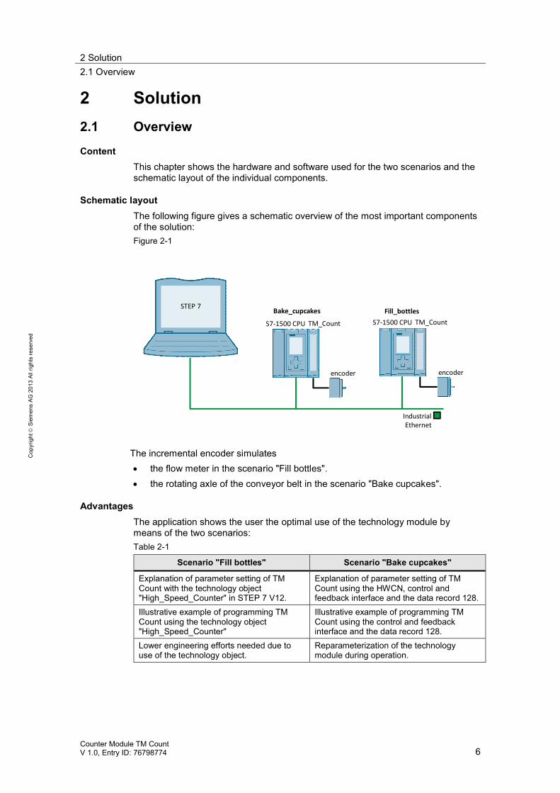
Schematic layoutThe following figure gives a schematic overview of the most important componentsof the solution:Figure 2-1
STEP 7
IndustrialEthernet
TM_CountS7-1500 CPUTM_CountS7-1500 CPU
encoder encoder
Bake_cupcakes Fill_bottles
The incremental encoder simulates the flow meter in the scenario "Fill bottles". the rotating axle of the conveyor belt in the scenario "Bake cupcakes".
AdvantagesThe application shows the user the optimal use of the technology module bymeans of the two scenarios:Table 2-1
Scenario "Fill bottles" Scenario "Bake cupcakes"
Explanation of parameter setting of TMCount with the technology object"High_Speed_Counter" in STEP 7 V12.
Explanation of parameter setting of TMCount using the HWCN, control andfeedback interface and the data record 128.
Illustrative example of programming TMCount using the technology object"High_Speed_Counter"
Illustrative example of programming TMCount using the control and feedbackinterface and the data record 128.
Lower engineering efforts needed due touse of the technology object.
Reparameterization of the technologymodule during operation.
2 Solution2.1 Overview
Counter Module TM CountV 1.0, Entry ID: 76798774 7
Cop
yrig
htSi
emen
sAG
2013
Allr
ight
sre
serv
ed
Note When the counter module parameters are set via the technology object, only themode "Count" is adjustable, not the mode "Measure".
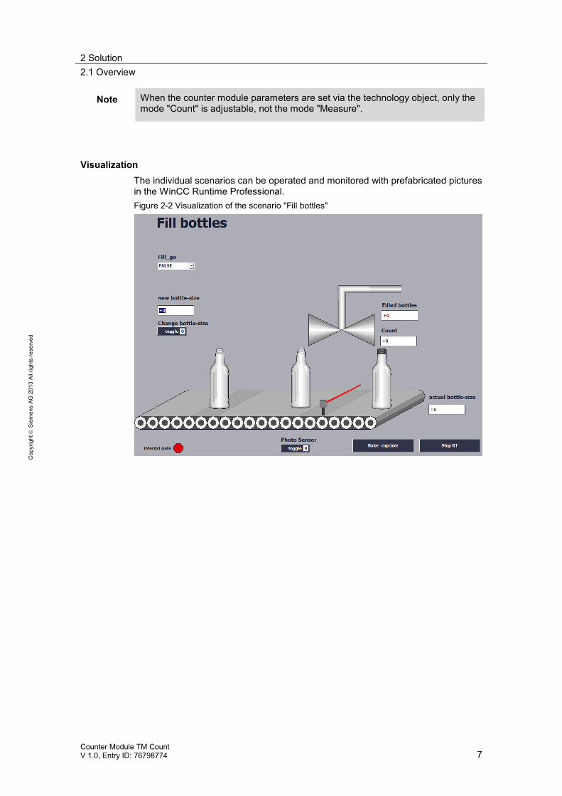
VisualizationThe individual scenarios can be operated and monitored with prefabricated picturesin the WinCC Runtime Professional.Figure 2-2 Visualization of the scenario "Fill bottles"
2 Solution2.1 Overview
Counter Module TM CountV 1.0, Entry ID: 76798774 8
Cop
yrig
htSi
emen
sAG
2013
Allr
ight
sre
serv
ed
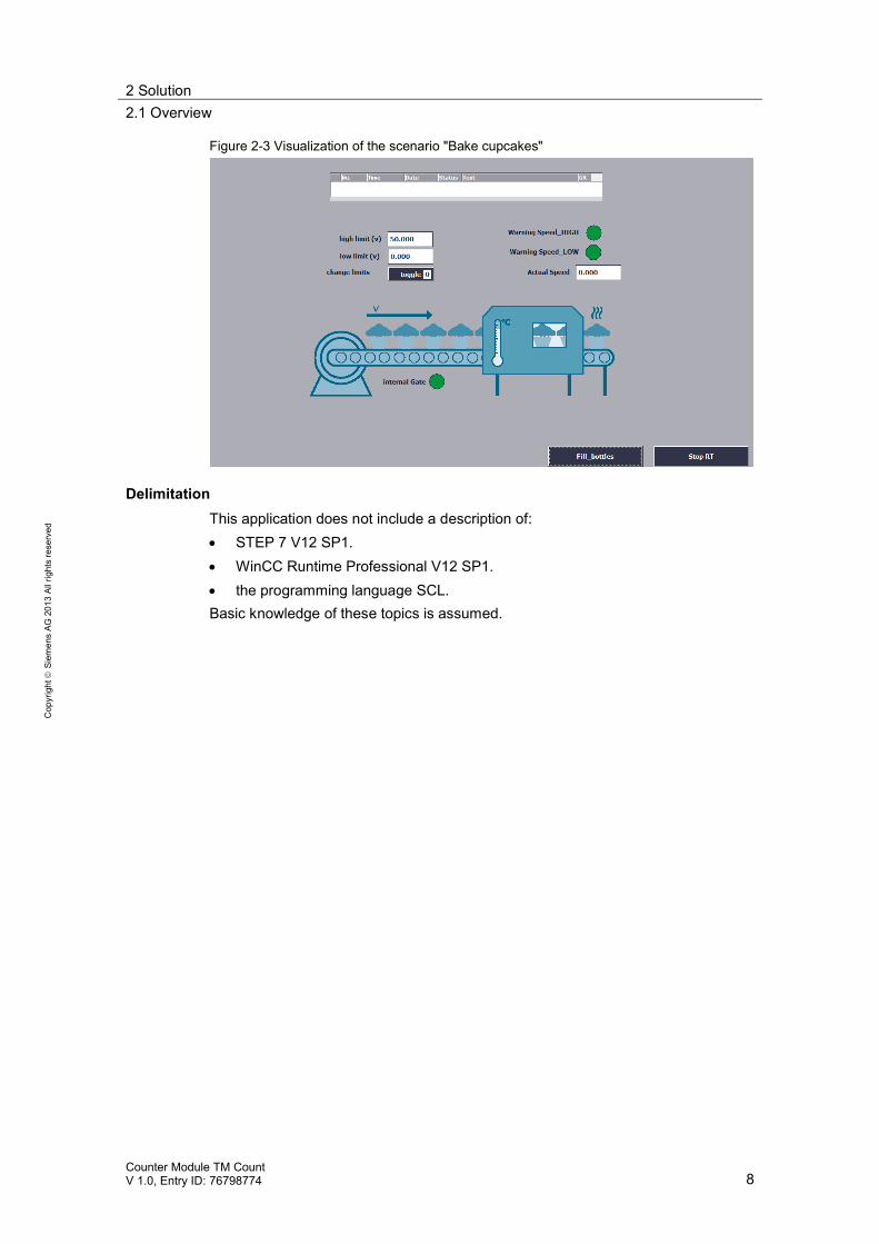
Figure 2-3 Visualization of the scenario "Bake cupcakes"
DelimitationThis application does not include a description of: STEP 7 V12 SP1. WinCC Runtime Professional V12 SP1. the programming language SCL.
Basic knowledge of these topics is assumed.
2 Solution2.2 Hardware and software components
Counter Module TM CountV 1.0, Entry ID: 76798774 9
Cop
yrig
htSi
emen
sAG
2013
Allr
ight
sre
serv
ed
2.2 Hardware and software components
2.2.1 Validity
This application is valid for STEP 7 from V12 S7-1500 FW 1.1
2.2.2 Components used
This application has been generated with the following components:
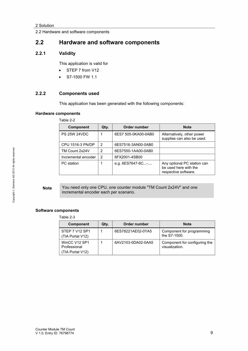
Hardware componentsTable 2-2
Component Qty. Order number Note
PS 25W 24VDC 1 6ES7 505-0KA00-0AB0 Alternatively, other powersupplies can also be used.
CPU 1516-3 PN/DP 2 6ES7516-3AN00-0AB0TM Count 2x24V 2 6ES7550-1AA00-0AB0Incremental encoder 2 6FX2001-4SB00PC station 1 e.g. 6ES7647-6C...-.... Any optional PC station can
be used here with therespective software.
Note You need only one CPU, one counter module "TM Count 2x24V" and oneincremental encoder each per scenario.
Software componentsTable 2-3
Component Qty. Order number Note
STEP 7 V12 SP1(TIA Portal V12)
1 6ES78221AE02-0YA5 Component for programmingthe S7-1500.
WinCC V12 SP1Professional(TIA Portal V12)
1 6AV2103-0DA02-0AA5 Component for configuring thevisualization.
2 Solution2.2 Hardware and software components
Counter Module TM CountV 1.0, Entry ID: 76798774 10
Cop
yrig
htSi
emen
sAG
2013
Allr
ight
sre
serv
ed
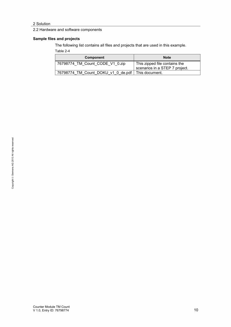
Sample files and projectsThe following list contains all files and projects that are used in this example.Table 2-4
Component Note
76798774_TM_Count_CODE_V1_0.zip This zipped file contains thescenarios in a STEP 7 project.
76798774_TM_Count_DOKU_v1_0_de.pdf This document.
3 Function Principle: Scenario "Fill bottles"3.1 General overview
Counter Module TM CountV 1.0, Entry ID: 76798774 11
Cop
yrig
htSi
emen
sAG
2013
Allr
ight
sre
serv
ed
3 Function Principle: Scenario "Fill bottles"The scenario "Fill bottles" is parameterized and controlled by the technologymodule "TM Count 2x24V" via the technology object "High_Speed_Counter". Thetechnology object "High_Speed_Counter" provides a simple graphic support forparameterization and a block for programming the TM Count.
3.1 General overview
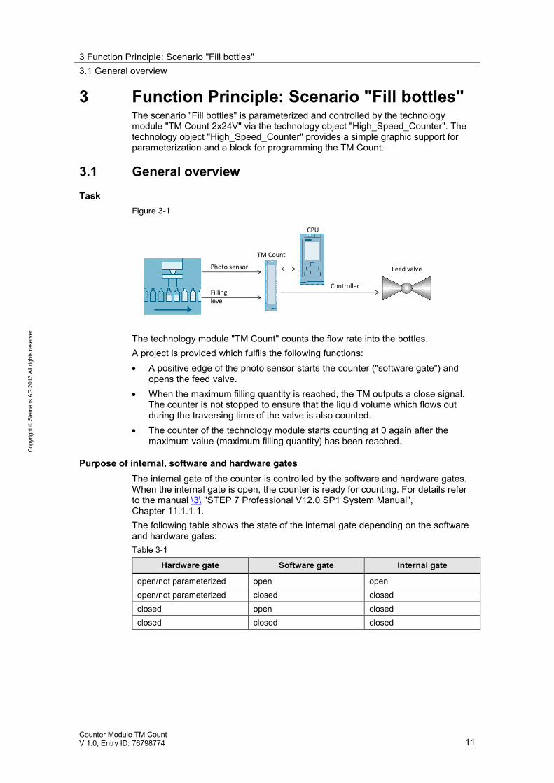
TaskFigure 3-1
Photo sensor Feed valve
Controller
CPU
Fillinglevel
TM Count
The technology module "TM Count" counts the flow rate into the bottles.A project is provided which fulfils the following functions: A positive edge of the photo sensor starts the counter ("software gate") and
opens the feed valve. When the maximum filling quantity is reached, the TM outputs a close signal.
The counter is not stopped to ensure that the liquid volume which flows outduring the traversing time of the valve is also counted.
The counter of the technology module starts counting at 0 again after themaximum value (maximum filling quantity) has been reached.
Purpose of internal, software and hardware gatesThe internal gate of the counter is controlled by the software and hardware gates.When the internal gate is open, the counter is ready for counting. For details referto the manual \3\ "STEP 7 Professional V12.0 SP1 System Manual",Chapter 11.1.1.1.The following table shows the state of the internal gate depending on the softwareand hardware gates:Table 3-1
Hardware gate Software gate Internal gate
open/not parameterized open openopen/not parameterized closed closedclosed open closedclosed closed closed
3 Function Principle: Scenario "Fill bottles"3.1 General overview
Counter Module TM CountV 1.0, Entry ID: 76798774 12
Cop
yrig
htSi
emen
sAG
2013
Allr
ight
sre
serv
ed
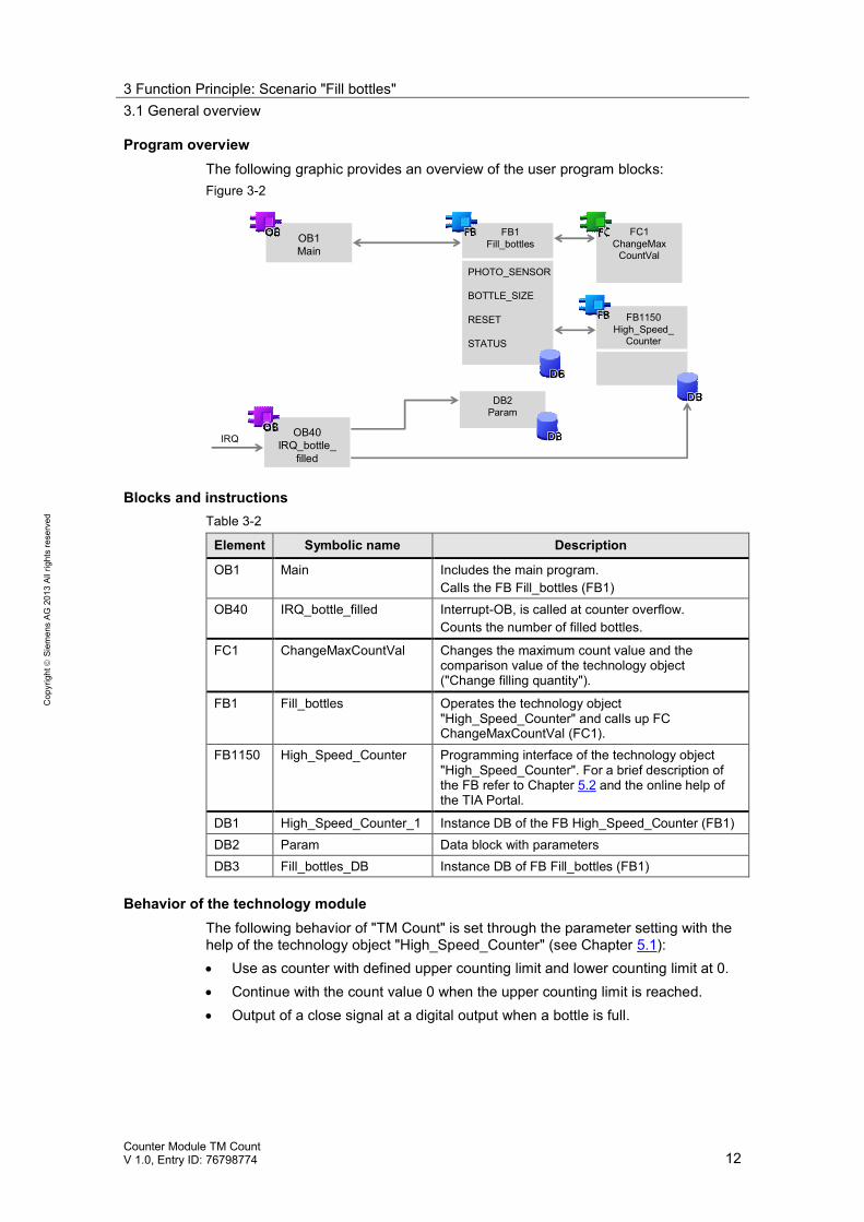
Program overviewThe following graphic provides an overview of the user program blocks:Figure 3-2
OB1Main
OB40IRQ_bottle_
filled
IRQ
FB1Fill_bottles
FC1ChangeMax
CountVal
DB2Param
PHOTO_SENSOR
BOTTLE_SIZE
RESET
STATUS
FB1150High_Speed_
Counter
Blocks and instructionsTable 3-2
Element Symbolic name Description
OB1 Main Includes the main program.Calls the FB Fill_bottles (FB1)
OB40 IRQ_bottle_filled Interrupt-OB, is called at counter overflow.Counts the number of filled bottles.
FC1 ChangeMaxCountVal Changes the maximum count value and thecomparison value of the technology object("Change filling quantity").
FB1 Fill_bottles Operates the technology object"High_Speed_Counter" and calls up FCChangeMaxCountVal (FC1).
FB1150 High_Speed_Counter Programming interface of the technology object"High_Speed_Counter". For a brief description ofthe FB refer to Chapter 5.2 and the online help ofthe TIA Portal.
DB1 High_Speed_Counter_1 Instance DB of the FB High_Speed_Counter (FB1)DB2 Param Data block with parametersDB3 Fill_bottles_DB Instance DB of FB Fill_bottles (FB1)
Behavior of the technology moduleThe following behavior of "TM Count" is set through the parameter setting with thehelp of the technology object "High_Speed_Counter" (see Chapter 5.1): Use as counter with defined upper counting limit and lower counting limit at 0. Continue with the count value 0 when the upper counting limit is reached. Output of a close signal at a digital output when a bottle is full.
3 Function Principle: Scenario "Fill bottles"3.2 Functions of the user program
Counter Module TM CountV 1.0, Entry ID: 76798774 13
Cop
yrig
htSi
emen
sAG
2013
Allr
ight
sre
serv
ed
3.2 Functions of the user program
Overview of the functionsThe user program realizes the following functions:Table 3-3
Function realized in
FB"Fill_bottles"
OB"IRQ_bottle_filled"
Parametersetting
Start of counting upon a trigger. X - -Provision of digital output signal forcontrol of a valve.
X - X
Stop of counting when sensordetects no bottle.
X - -
Counting the full bottles. X X -Changing filling quantity of bottles. X - XAfter "overflow" continue withcounting from 0.
- - X
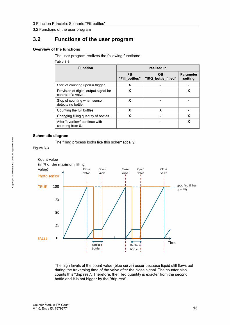
Schematic diagramThe filling process looks like this schematically:
Figure 3-3
Count value(in % of the maximum fillingvalue)
25
50
75
100
0Time
Closevalve
Closevalve
Closevalve
specified fillingquantity
Replacebottle
Replacebottle
Photo sensor
TRUE
FALSE
Openvalve
Openvalve
The high levels of the count value (blue curve) occur because liquid still flows outduring the traversing time of the valve after the close signal. The counter alsocounts this "drip rest". Therefore, the filled quantity is exacter from the secondbottle and it is not bigger by the "drip rest".
3 Function Principle: Scenario "Fill bottles"3.3 The function block "Fill_bottles" (FB1)
Counter Module TM CountV 1.0, Entry ID: 76798774 14
Cop
yrig
htSi
emen
sAG
2013
Allr
ight
sre
serv
ed
3.3 The function block "Fill_bottles" (FB1)
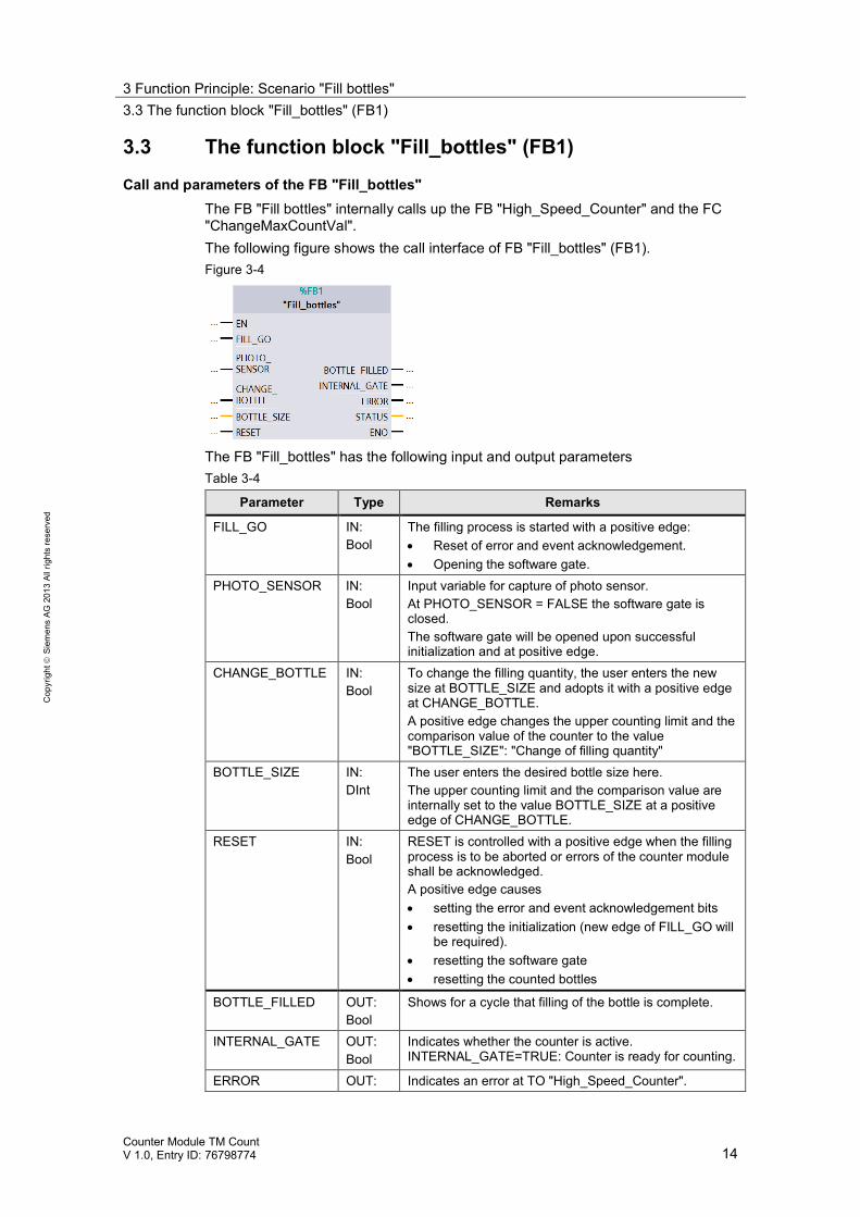
Call and parameters of the FB "Fill_bottles"The FB "Fill bottles" internally calls up the FB "High_Speed_Counter" and the FC"ChangeMaxCountVal".The following figure shows the call interface of FB "Fill_bottles" (FB1).Figure 3-4
The FB "Fill_bottles" has the following input and output parametersTable 3-4
Parameter Type Remarks
FILL_GO IN:Bool
The filling process is started with a positive edge: Reset of error and event acknowledgement. Opening the software gate.
PHOTO_SENSOR IN:Bool
Input variable for capture of photo sensor.At PHOTO_SENSOR = FALSE the software gate isclosed.The software gate will be opened upon successfulinitialization and at positive edge.
CHANGE_BOTTLE IN:Bool
To change the filling quantity, the user enters the newsize at BOTTLE_SIZE and adopts it with a positive edgeat CHANGE_BOTTLE.A positive edge changes the upper counting limit and thecomparison value of the counter to the value"BOTTLE_SIZE": "Change of filling quantity"
BOTTLE_SIZE IN:DInt
The user enters the desired bottle size here.The upper counting limit and the comparison value areinternally set to the value BOTTLE_SIZE at a positiveedge of CHANGE_BOTTLE.
RESET IN:Bool
RESET is controlled with a positive edge when the fillingprocess is to be aborted or errors of the counter moduleshall be acknowledged.A positive edge causes setting the error and event acknowledgement bits resetting the initialization (new edge of FILL_GO will
be required). resetting the software gate resetting the counted bottles
BOTTLE_FILLED OUT:Bool
Shows for a cycle that filling of the bottle is complete.
INTERNAL_GATE OUT:Bool
Indicates whether the counter is active.INTERNAL_GATE=TRUE: Counter is ready for counting.
ERROR OUT: Indicates an error at TO "High_Speed_Counter".
3 Function Principle: Scenario "Fill bottles"3.3 The function block "Fill_bottles" (FB1)
Counter Module TM CountV 1.0, Entry ID: 76798774 15
Cop
yrig
htSi
emen
sAG
2013
Allr
ight
sre
serv
ed
Parameter Type RemarksBool Interconnect this output to read out and evaluate the
parameter STATUS in the case of an error.STATUS OUT:
WordOutputs the error ID of the TO "High_Speed_Counter" inthe case of error. For a description of the error IDs referto the online help of the TIA Portal.
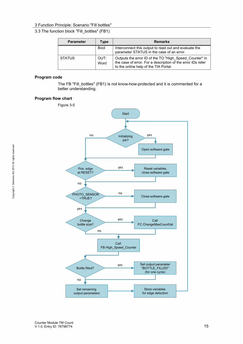
Program codeThe FB "Fill_bottles" (FB1) is not know-how-protected and it is commented for abetter understanding.
Program flow chartFigure 3-5
Start
Initializingjob?
Open software gate
yes
Pos. edgeat RESET?
no
yes Reset variables,close software gate
no
PHOTO_SENSOR=TRUE?
noClose software gate
Changebottle size?
yes CallFC ChangeMaxCountVal
Bottle filled?yes Set output parameter
"BOTTLE_FILLED"(for one cycle)
Set remainingoutput parameters
Store variablesfor edge detection
CallFB High_Speed_Counter
yes
no
no
3 Function Principle: Scenario "Fill bottles"3.4 The function "ChangeMaxCountVal" (FC1)
Counter Module TM CountV 1.0, Entry ID: 76798774 16
Cop
yrig
htSi
emen
sAG
2013
Allr
ight
sre
serv
ed
3.4 The function "ChangeMaxCountVal" (FC1)
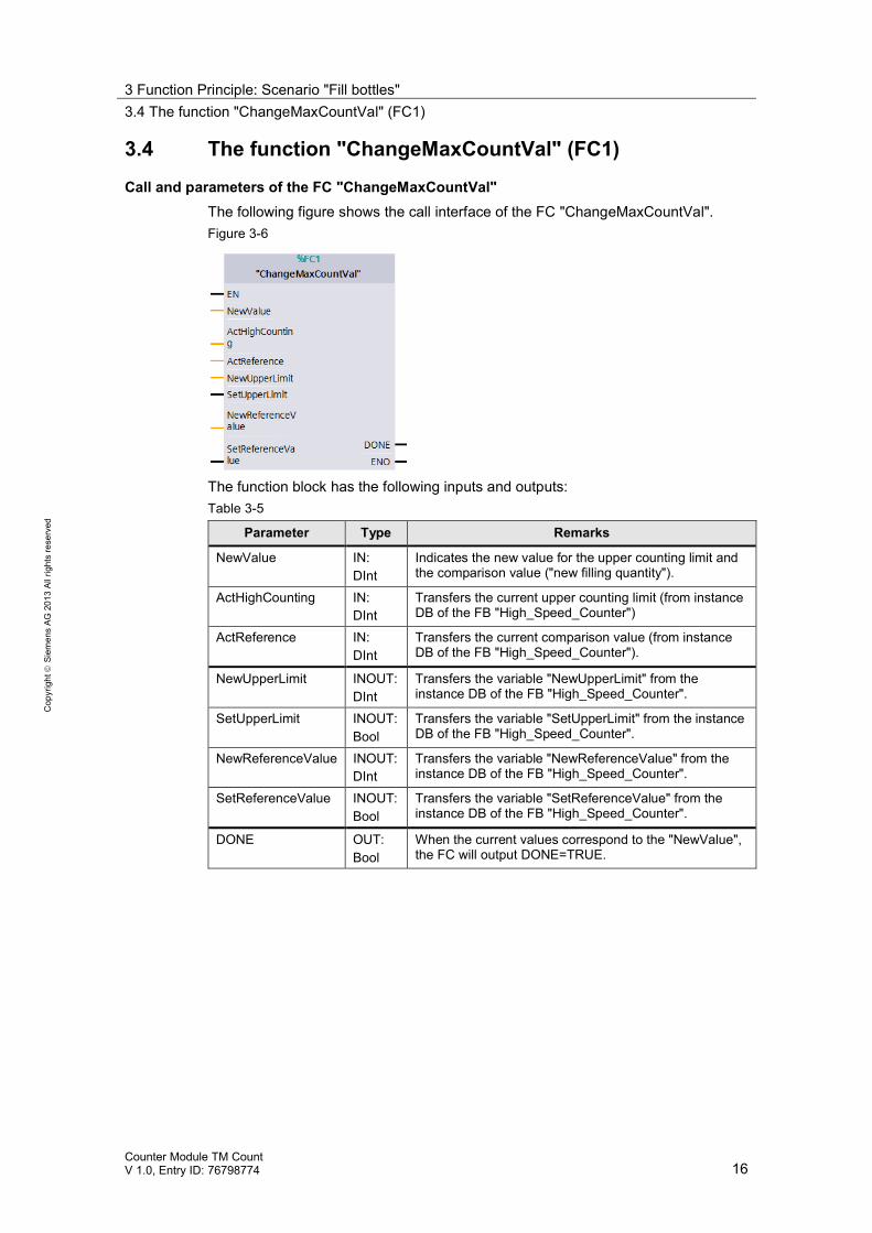
Call and parameters of the FC "ChangeMaxCountVal"The following figure shows the call interface of the FC "ChangeMaxCountVal".Figure 3-6
The function block has the following inputs and outputs:Table 3-5
Parameter Type Remarks
NewValue IN:DInt
Indicates the new value for the upper counting limit andthe comparison value ("new filling quantity").
ActHighCounting IN:DInt
Transfers the current upper counting limit (from instanceDB of the FB "High_Speed_Counter")
ActReference IN:DInt
Transfers the current comparison value (from instanceDB of the FB "High_Speed_Counter").
NewUpperLimit INOUT:DInt
Transfers the variable "NewUpperLimit" from theinstance DB of the FB "High_Speed_Counter".
SetUpperLimit INOUT:Bool
Transfers the variable "SetUpperLimit" from the instanceDB of the FB "High_Speed_Counter".
NewReferenceValue INOUT:DInt
Transfers the variable "NewReferenceValue" from theinstance DB of the FB "High_Speed_Counter".
SetReferenceValue INOUT:Bool
Transfers the variable "SetReferenceValue" from theinstance DB of the FB "High_Speed_Counter".
DONE OUT:Bool
When the current values correspond to the "NewValue",the FC will output DONE=TRUE.
3 Function Principle: Scenario "Fill bottles"3.4 The function "ChangeMaxCountVal" (FC1)
Counter Module TM CountV 1.0, Entry ID: 76798774 17
Cop
yrig
htSi
emen
sAG
2013
Allr
ight
sre
serv
ed
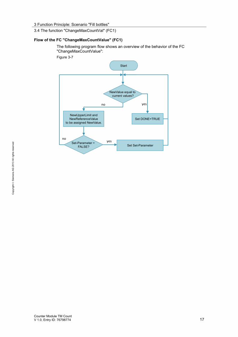
Flow of the FC "ChangeMaxCountValue" (FC1)The following program flow shows an overview of the behavior of the FC"ChangeMaxCountValue":Figure 3-7
Start
Set Set-Parameter
no
NewUpperLimit andNewReferenceValue
to be assigned NewValue.
NewValue equal tocurrent values?
yes
Set-Parameter =FALSE?
no
Set DONE=TRUE
yes
3 Function Principle: Scenario "Fill bottles"3.5 The function block "High_Speed_Counter" (FB1150)
Counter Module TM CountV 1.0, Entry ID: 76798774 18
Cop
yrig
htSi
emen
sAG
2013
Allr
ight
sre
serv
ed
3.5 The function block "High_Speed_Counter" (FB1150)
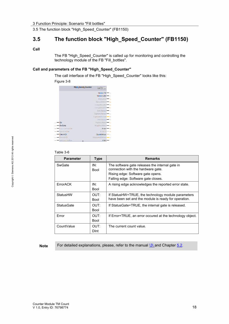
CallThe FB "High_Speed_Counter" is called up for monitoring and controlling thetechnology module of the FB "Fill_bottles".
Call and parameters of the FB "High_Speed_Counter"The call interface of the FB "High_Speed_Counter" looks like this:Figure 3-8
Table 3-6
Parameter Type Remarks
SwGate IN:Bool
The software gate releases the internal gate inconnection with the hardware gate.Rising edge: Software gate opens.Falling edge: Software gate closes.
ErrorACK IN:Bool
A rising edge acknowledges the reported error state.
StatusHW OUT:Bool
If StatusHW=TRUE, the technology module parametershave been set and the module is ready for operation.
StatusGate OUT:Bool
If StatusGate=TRUE, the internal gate is released.
Error OUT:Bool
If Error=TRUE, an error occured at the technology object.
CountValue OUT:DInt
The current count value.
Note For detailed explanations, please, refer to the manual \3\ and Chapter 5.2.
4 Function Principle: Scenario "Bake cupcakes"4.1 General overview
Counter Module TM CountV 1.0, Entry ID: 76798774 19
Cop
yrig
htSi
emen
sAG
2013
Allr
ight
sre
serv
ed
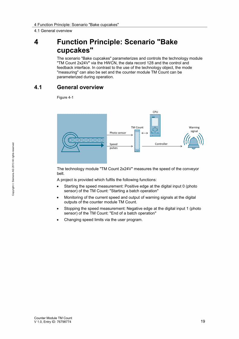
4 Function Principle: Scenario "Bakecupcakes"The scenario "Bake cupcakes" parameterizes and controls the technology module"TM Count 2x24V" via the HWCN, the data record 128 and the control andfeedback interface. In contrast to the use of the technology object, the mode"measuring" can also be set and the counter module TM Count can beparameterized during operation.
4.1 General overviewFigure 4-1
Photo sensor
Controller
CPU
Speedpulses
TM Count Warningsignal
The technology module "TM Count 2x24V" measures the speed of the conveyorbelt.A project is provided which fulfils the following functions: Starting the speed measurement: Positive edge at the digital input 0 (photo
sensor) of the TM Count: "Starting a batch operation" Monitoring of the current speed and output of warning signals at the digital
outputs of the counter module TM Count. Stopping the speed measurement: Negative edge at the digital input 1 (photo
sensor) of the TM Count: "End of a batch operation" Changing speed limits via the user program.
4 Function Principle: Scenario "Bake cupcakes"4.1 General overview
Counter Module TM CountV 1.0, Entry ID: 76798774 20
Cop
yrig
htSi
emen
sAG
2013
Allr
ight
sre
serv
ed
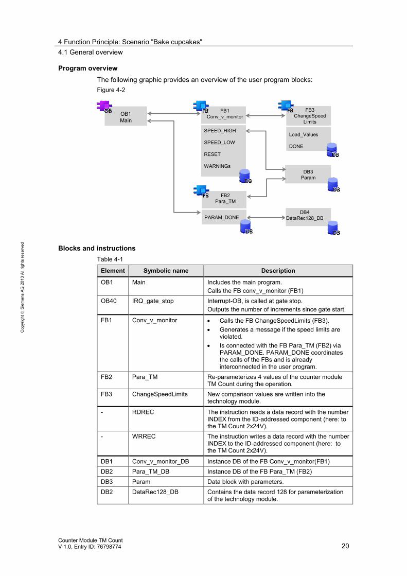
Program overviewThe following graphic provides an overview of the user program blocks:Figure 4-2
OB1Main
FB1Conv_v_monitor
DB4DataRec128_DB
DB3Param
SPEED_HIGH
SPEED_LOW
RESET
WARNINGs
FB2Para_TM
PARAM_DONE
FB3ChangeSpeed
Limits
Load_Values
DONE
Blocks and instructionsTable 4-1
Element Symbolic name Description
OB1 Main Includes the main program.Calls the FB conv_v_monitor (FB1)
OB40 IRQ_gate_stop Interrupt-OB, is called at gate stop.Outputs the number of increments since gate start.
FB1 Conv_v_monitor Calls the FB ChangeSpeedLimits (FB3). Generates a message if the speed limits are
violated. Is connected with the FB Para_TM (FB2) via
PARAM_DONE. PARAM_DONE coordinatesthe calls of the FBs and is alreadyinterconnected in the user program.
FB2 Para_TM Re-parameterizes 4 values of the counter moduleTM Count during the operation.
FB3 ChangeSpeedLimits New comparison values are written into thetechnology module.
- RDREC The instruction reads a data record with the numberINDEX from the ID-addressed component (here: tothe TM Count 2x24V).
- WRREC The instruction writes a data record with the numberINDEX to the ID-addressed component (here: tothe TM Count 2x24V).
DB1 Conv_v_monitor_DB Instance DB of the FB Conv_v_monitor(FB1)DB2 Para_TM_DB Instance DB of the FB Para_TM (FB2)DB3 Param Data block with parameters.DB2 DataRec128_DB Contains the data record 128 for parameterization
of the technology module.
4 Function Principle: Scenario "Bake cupcakes"4.1 General overview
Counter Module TM CountV 1.0, Entry ID: 76798774 21
Cop
yrig
htSi
emen
sAG
2013
Allr
ight
sre
serv
ed
Behavior of the technology moduleThe parameter setting in the HWCN is used to set the following behavior of the"TM Count": Using the TM Count for measuring the speed with the time basis "second". Hardware gate start through digital input 0. Hardware gate stop through digital input 1. Automatic setting of the outputs DQ0 and DQ1 when the configured
comparison values are exceeded or fallen below.
Note The parameters in the FB Para_TM (FB2) are transmitted in addition with thedata record 128 via the system functions RDREC and WRREC as an example ofparameterizing the technology module during the operation (see Chapter 5.3).
4 Function Principle: Scenario "Bake cupcakes"4.2 Functions of the user program
Counter Module TM CountV 1.0, Entry ID: 76798774 22
Cop
yrig
htSi
emen
sAG
2013
Allr
ight
sre
serv
ed
4.2 Functions of the user program
Overview of the functionsThe user program realizes the following functions:Table 4-2
Function realized in
FB"Conv_v_monitor"
FB"Para_TM"
Parametersetting
Start of measurement upon an externalinput signal.
- X X
Stop of measurement upon an externalinput signal.
- X X
Output of different warning signals whenthe set speed limits are exceeded andfallen below.
- - X
Generation of messages when the setspeed limits are exceeded and fallenbelow.
X - -
Changing the speed limits. X - -
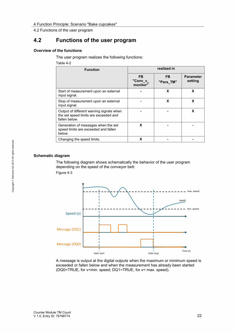
Schematic diagramThe following diagram shows schematically the behavior of the user programdepending on the speed of the conveyor belt:Figure 4-3
Speed (v)
Message (DQ1)
max. speed
min. speed
Gate start
speed
Gate stopTime (t)
Message (DQ0)
A message is output at the digital outputs when the maximum or minimum speed isexceeded or fallen below and when the measurement has already been started(DQ0=TRUE, for v<min. speed; DQ1=TRUE, for v< max. speed).
4 Function Principle: Scenario "Bake cupcakes"4.3 The function block "Conv_v_monitor" (FB1)
Counter Module TM CountV 1.0, Entry ID: 76798774 23
Cop
yrig
htSi
emen
sAG
2013
Allr
ight
sre
serv
ed
4.3 The function block "Conv_v_monitor" (FB1)
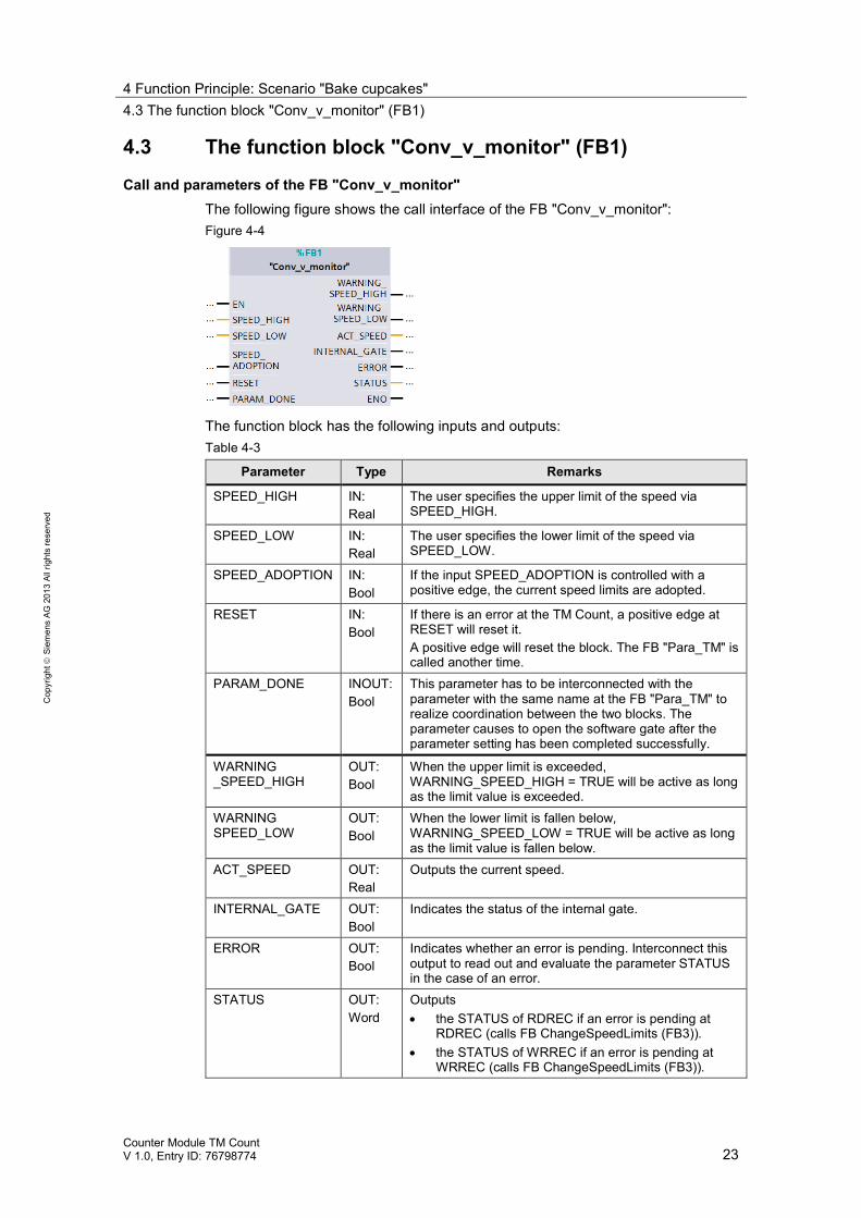
Call and parameters of the FB "Conv_v_monitor"The following figure shows the call interface of the FB "Conv_v_monitor":Figure 4-4
The function block has the following inputs and outputs:Table 4-3
Parameter Type Remarks
SPEED_HIGH IN:Real
The user specifies the upper limit of the speed viaSPEED_HIGH.
SPEED_LOW IN:Real
The user specifies the lower limit of the speed viaSPEED_LOW.
SPEED_ADOPTION IN:Bool
If the input SPEED_ADOPTION is controlled with apositive edge, the current speed limits are adopted.
RESET IN:Bool
If there is an error at the TM Count, a positive edge atRESET will reset it.A positive edge will reset the block. The FB "Para_TM" iscalled another time.
PARAM_DONE INOUT:Bool
This parameter has to be interconnected with theparameter with the same name at the FB "Para_TM" torealize coordination between the two blocks. Theparameter causes to open the software gate after theparameter setting has been completed successfully.
WARNING_SPEED_HIGH
OUT:Bool
When the upper limit is exceeded,WARNING_SPEED_HIGH = TRUE will be active as longas the limit value is exceeded.
WARNINGSPEED_LOW
OUT:Bool
When the lower limit is fallen below,WARNING_SPEED_LOW = TRUE will be active as longas the limit value is fallen below.
ACT_SPEED OUT:Real
Outputs the current speed.
INTERNAL_GATE OUT:Bool
Indicates the status of the internal gate.
ERROR OUT:Bool
Indicates whether an error is pending. Interconnect thisoutput to read out and evaluate the parameter STATUSin the case of an error.
STATUS OUT:Word
Outputs the STATUS of RDREC if an error is pending at
RDREC (calls FB ChangeSpeedLimits (FB3)). the STATUS of WRREC if an error is pending at
WRREC (calls FB ChangeSpeedLimits (FB3)).
4 Function Principle: Scenario "Bake cupcakes"4.3 The function block "Conv_v_monitor" (FB1)
Counter Module TM CountV 1.0, Entry ID: 76798774 24
Cop
yrig
htSi
emen
sAG
2013
Allr
ight
sre
serv
ed
Parameter Type Remarks
the STATUS 16#0001_0001 if the specified upperlimit is smaller than the lower limit of the speed.
For information on the purpose of the STATUS ofWRREC and RDREC refer to the online help of the TIAPortal.
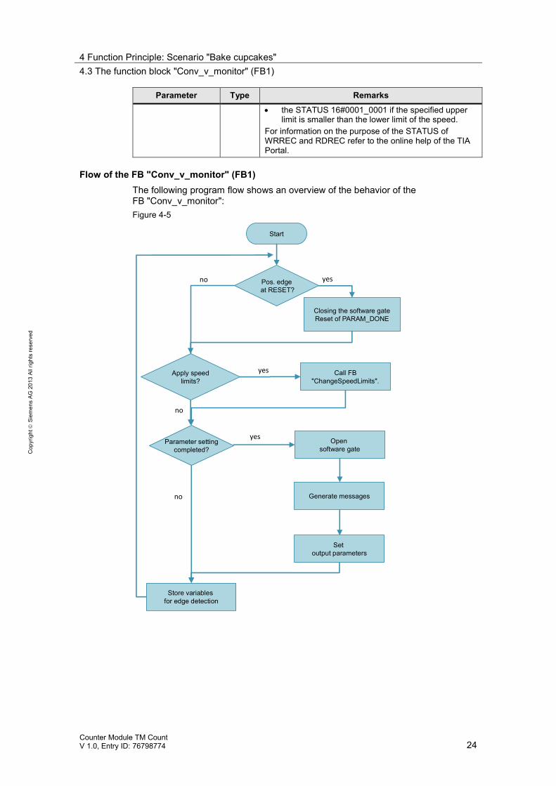
Flow of the FB "Conv_v_monitor" (FB1)The following program flow shows an overview of the behavior of theFB "Conv_v_monitor":Figure 4-5
Start
Pos. edgeat RESET?
Closing the software gateReset of PARAM_DONE
yes
Apply speedlimits?
no
yes Call FB"ChangeSpeedLimits".
no
Parameter settingcompleted?
yes Opensoftware gate
Setoutput parameters
Store variablesfor edge detection
Generate messagesno
4 Function Principle: Scenario "Bake cupcakes"4.4 The function block "Para_TM" (FB2)
Counter Module TM CountV 1.0, Entry ID: 76798774 25
Cop
yrig
htSi
emen
sAG
2013
Allr
ight
sre
serv
ed
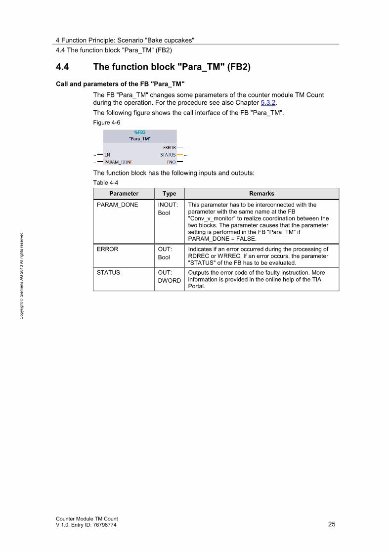
4.4 The function block "Para_TM" (FB2)
Call and parameters of the FB "Para_TM"The FB "Para_TM" changes some parameters of the counter module TM Countduring the operation. For the procedure see also Chapter 5.3.2.The following figure shows the call interface of the FB "Para_TM".Figure 4-6
The function block has the following inputs and outputs:Table 4-4
Parameter Type Remarks
PARAM_DONE INOUT:Bool
This parameter has to be interconnected with theparameter with the same name at the FB"Conv_v_monitor" to realize coordination between thetwo blocks. The parameter causes that the parametersetting is performed in the FB "Para_TM" ifPARAM_DONE = FALSE.
ERROR OUT:Bool
Indicates if an error occurred during the processing ofRDREC or WRREC. If an error occurs, the parameter"STATUS" of the FB has to be evaluated.
STATUS OUT:DWORD
Outputs the error code of the faulty instruction. Moreinformation is provided in the online help of the TIAPortal.
4 Function Principle: Scenario "Bake cupcakes"4.5 The function block "ChangeSpeedLimits" (FB3)
Counter Module TM CountV 1.0, Entry ID: 76798774 26
Cop
yrig
htSi
emen
sAG
2013
Allr
ight
sre
serv
ed
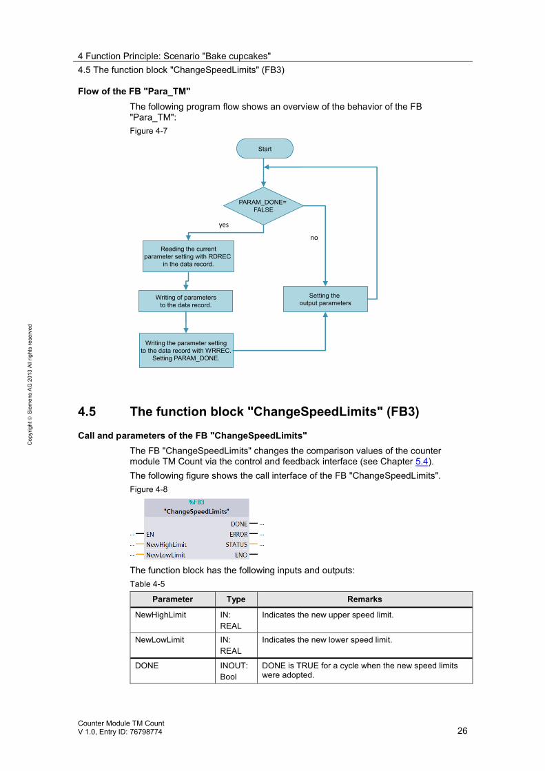
Flow of the FB "Para_TM"The following program flow shows an overview of the behavior of the FB"Para_TM":Figure 4-7
Start
Writing of parametersto the data record.
yes
Writing the parameter settingto the data record with WRREC.
Setting PARAM_DONE.
Reading the currentparameter setting with RDREC
in the data record.
PARAM_DONE=FALSE
Setting theoutput parameters
no
4.5 The function block "ChangeSpeedLimits" (FB3)
Call and parameters of the FB "ChangeSpeedLimits"The FB "ChangeSpeedLimits" changes the comparison values of the countermodule TM Count via the control and feedback interface (see Chapter 5.4).The following figure shows the call interface of the FB "ChangeSpeedLimits".Figure 4-8
The function block has the following inputs and outputs:Table 4-5
Parameter Type Remarks
NewHighLimit IN:REAL
Indicates the new upper speed limit.
NewLowLimit IN:REAL
Indicates the new lower speed limit.
DONE INOUT:Bool
DONE is TRUE for a cycle when the new speed limitswere adopted.
4 Function Principle: Scenario "Bake cupcakes"4.5 The function block "ChangeSpeedLimits" (FB3)
Counter Module TM CountV 1.0, Entry ID: 76798774 27
Cop
yrig
htSi
emen
sAG
2013
Allr
ight
sre
serv
ed
Parameter Type Remarks
ERROR OUT:Bool
Indicates if an error occurred in changing thecomparison values. If an error occurs, the parameterSTATUS of the FB "ChangeSpeedLimits" has to beevaluated.
STATUS OUT:Word
The following error codes can be output: 16#0001: Module has not yet started. 16#0201: Loading of the comparison values has
failed.
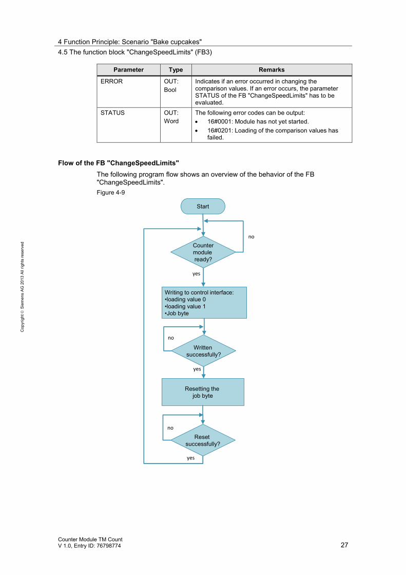
Flow of the FB "ChangeSpeedLimits"The following program flow shows an overview of the behavior of the FB"ChangeSpeedLimits".Figure 4-9
Start
yes
Resetting thejob byte
Writing to control interface:•loading value 0•loading value 1•Job byte
Countermoduleready?
no
Writtensuccessfully?
Resetsuccessfully?
yes
no
no
yes
4 Function Principle: Scenario "Bake cupcakes"4.6 The instructions "RDREC" and "WRREC"
Counter Module TM CountV 1.0, Entry ID: 76798774 28
Cop
yrig
htSi
emen
sAG
2013
Allr
ight
sre
serv
ed
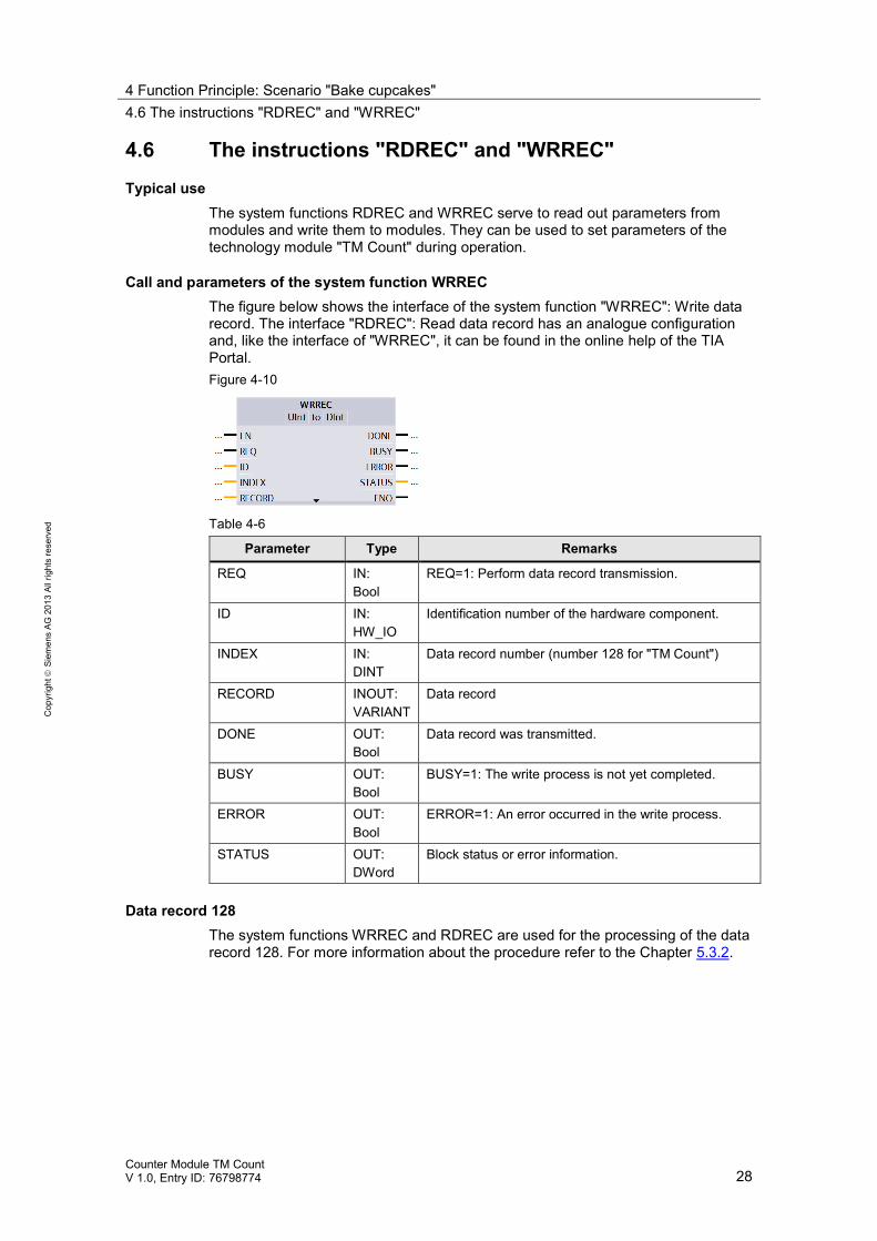
4.6 The instructions "RDREC" and "WRREC"
Typical useThe system functions RDREC and WRREC serve to read out parameters frommodules and write them to modules. They can be used to set parameters of thetechnology module "TM Count" during operation.
Call and parameters of the system function WRRECThe figure below shows the interface of the system function "WRREC": Write datarecord. The interface "RDREC": Read data record has an analogue configurationand, like the interface of "WRREC", it can be found in the online help of the TIAPortal.Figure 4-10
Table 4-6
Parameter Type Remarks
REQ IN:Bool
REQ=1: Perform data record transmission.
ID IN:HW_IO
Identification number of the hardware component.
INDEX IN:DINT
Data record number (number 128 for "TM Count")
RECORD INOUT:VARIANT
Data record
DONE OUT:Bool
Data record was transmitted.
BUSY OUT:Bool
BUSY=1: The write process is not yet completed.
ERROR OUT:Bool
ERROR=1: An error occurred in the write process.
STATUS OUT:DWord
Block status or error information.
Data record 128The system functions WRREC and RDREC are used for the processing of the datarecord 128. For more information about the procedure refer to the Chapter 5.3.2.

5 Configuration and Settings of the Technology Module4.6 The instructions "RDREC" and "WRREC"
Counter Module TM CountV 1.0, Entry ID: 76798774 29
Cop
yrig
htSi
emen
sAG
2013
Allr
ight
sre
serv
ed
5 Configuration and Settings of theTechnology Module
Possible parameter setting methodsVarious options exist in STEP 7 for using the technology module "TM Count2x24V". Some parameter settings can be made in the hardware configuration (HWCN). The technology object "High_Speed_Counter" supports the user in the
parameter setting and programming of the counter module TM Count through agraphical user interface and the FB "High_Speed_Counter".
User who do not want to use the technology object can set parameters of thecounter module TM Count with the data record 128 and control the countermodule via the control and feedback interface.
Advantages and disadvantages of the technology objectAdvantages: easier and faster parameter setting via the graphical user interface. simpler programming via the function block High_Speed_Counter.
Disadvantages: no re-parameterization of the counter module TM Count during operation. Only available for the mode "Counting".
Recommendation:Use the technology object always when you create an application in which you usethe mode "counting" and in which you do not want to re-parameterize the countermodule during operation.
Realized parameter setting methodsThe parameters of the technology module are set in different ways in the twoscenarios in this application. This chapter describes the procedure for parametersetting and programming. Scenario "Fill bottles":
Set the parameters and program the TM Count via the technology object"High_Speed_Counter": Chapter 5.1 and Chapter 5.2.
Scenario "Bake cupcakes"Set parameters and program the TM Count via the data record 128 and thecontrol and feedback interface: Chapter 5.3 and Chapter 5.4.
5 Configuration and Settings of the Technology Module5.1 Setting parameters with the technology object
Counter Module TM CountV 1.0, Entry ID: 76798774 30
Cop
yrig
htSi
emen
sAG
2013
Allr
ight
sre
serv
ed
5.1 Setting parameters with the technology object
The technology object "High_Speed_Counter" provides the user with a graphical user interface for setting parameters with a function block for controlling the technology module for the programming
and, thus, it reduces the engineering effort.
5.1.1 Hardware configuration (HWCN)
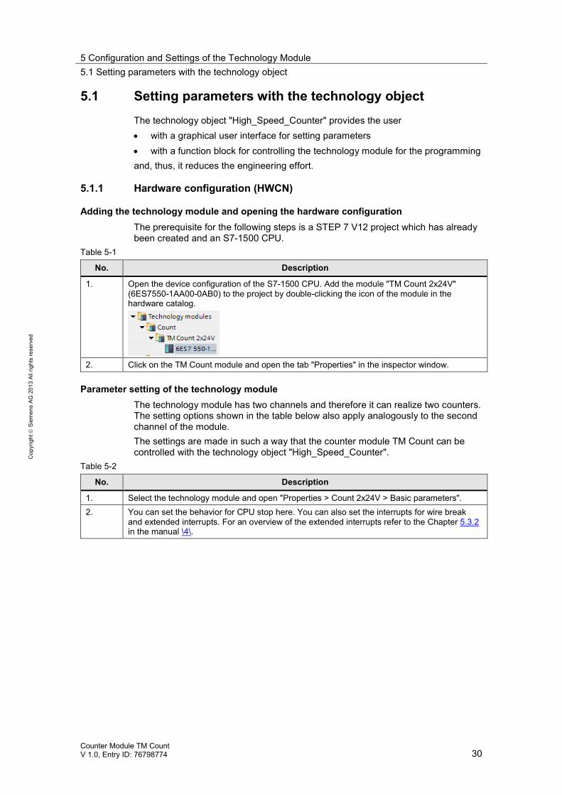
Adding the technology module and opening the hardware configurationThe prerequisite for the following steps is a STEP 7 V12 project which has alreadybeen created and an S7-1500 CPU.
Table 5-1
No. Description
1. Open the device configuration of the S7-1500 CPU. Add the module "TM Count 2x24V"(6ES7550-1AA00-0AB0) to the project by double-clicking the icon of the module in thehardware catalog.
2. Click on the TM Count module and open the tab "Properties" in the inspector window.
Parameter setting of the technology moduleThe technology module has two channels and therefore it can realize two counters.The setting options shown in the table below also apply analogously to the secondchannel of the module.The settings are made in such a way that the counter module TM Count can becontrolled with the technology object "High_Speed_Counter".
Table 5-2
No. Description
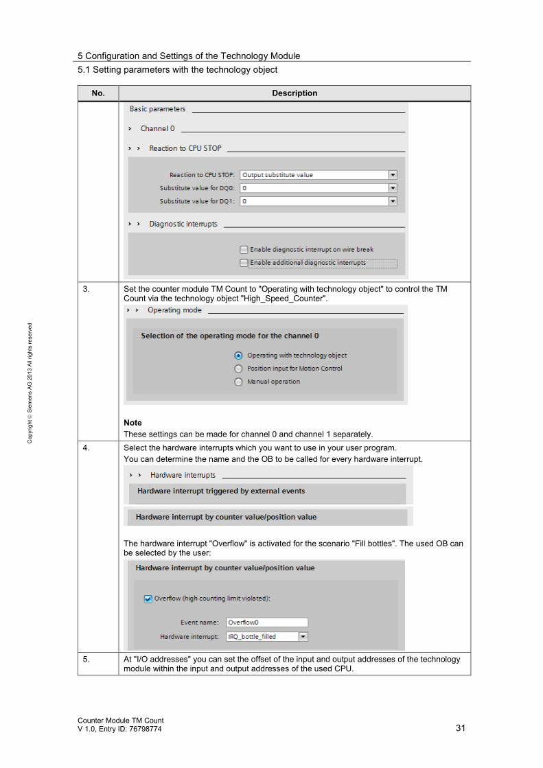
1. Select the technology module and open "Properties > Count 2x24V > Basic parameters".2. You can set the behavior for CPU stop here. You can also set the interrupts for wire break
and extended interrupts. For an overview of the extended interrupts refer to the Chapter 5.3.2in the manual \4\.
5 Configuration and Settings of the Technology Module5.1 Setting parameters with the technology object
Counter Module TM CountV 1.0, Entry ID: 76798774 31
Cop
yrig
htSi
emen
sAG
2013
Allr
ight
sre
serv
ed
No. Description
3. Set the counter module TM Count to "Operating with technology object" to control the TMCount via the technology object "High_Speed_Counter".
NoteThese settings can be made for channel 0 and channel 1 separately.
4. Select the hardware interrupts which you want to use in your user program.You can determine the name and the OB to be called for every hardware interrupt.
The hardware interrupt "Overflow" is activated for the scenario "Fill bottles". The used OB canbe selected by the user:
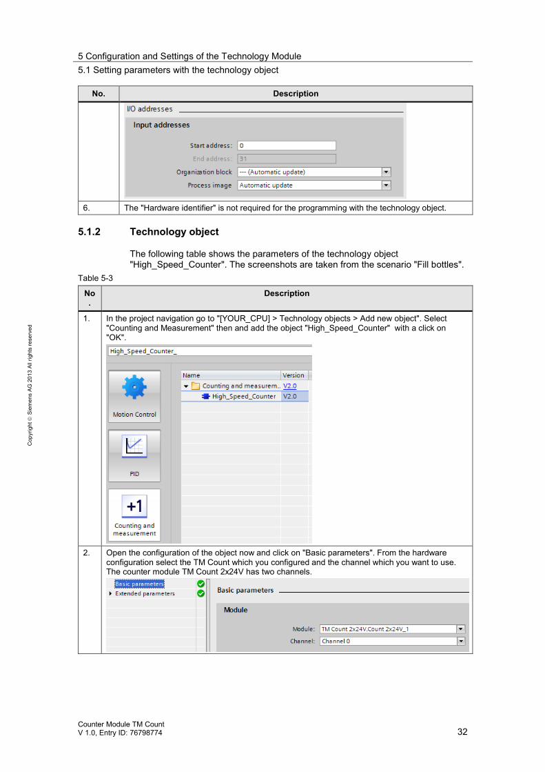
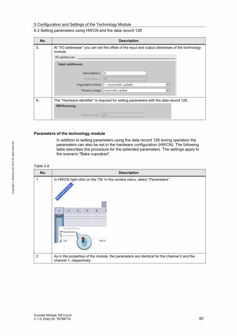
5. At "I/O addresses" you can set the offset of the input and output addresses of the technologymodule within the input and output addresses of the used CPU.
5 Configuration and Settings of the Technology Module5.1 Setting parameters with the technology object
Counter Module TM CountV 1.0, Entry ID: 76798774 32
Cop
yrig
htSi
emen
sAG
2013
Allr
ight
sre
serv
ed
No. Description
6. The "Hardware identifier" is not required for the programming with the technology object.
5.1.2 Technology object
The following table shows the parameters of the technology object"High_Speed_Counter". The screenshots are taken from the scenario "Fill bottles".
Table 5-3
No.
Description
1. In the project navigation go to "[YOUR_CPU] > Technology objects > Add new object". Select"Counting and Measurement" then and add the object "High_Speed_Counter" with a click on"OK".
2. Open the configuration of the object now and click on "Basic parameters". From the hardwareconfiguration select the TM Count which you configured and the channel which you want to use.The counter module TM Count 2x24V has two channels.

5 Configuration and Settings of the Technology Module5.1 Setting parameters with the technology object
Counter Module TM CountV 1.0, Entry ID: 76798774 33
Cop
yrig
htSi
emen
sAG
2013
Allr
ight
sre
serv
ed
No.
Description
3. At "Extended parameters" specify the input signals of the module. In addition, set the counter andmeasurement behavior and the behavior of the digital inputs and outputs.At "Counter inputs" specify the input signals such as the type of encoder and signal evaluation.
4. The behavior of the counter at the counting limits and the actual counting limits are set at "Counterbehavior".
5 Configuration and Settings of the Technology Module5.1 Setting parameters with the technology object
Counter Module TM CountV 1.0, Entry ID: 76798774 34
Cop
yrig
htSi
emen
sAG
2013
Allr
ight
sre
serv
ed
No.
Description
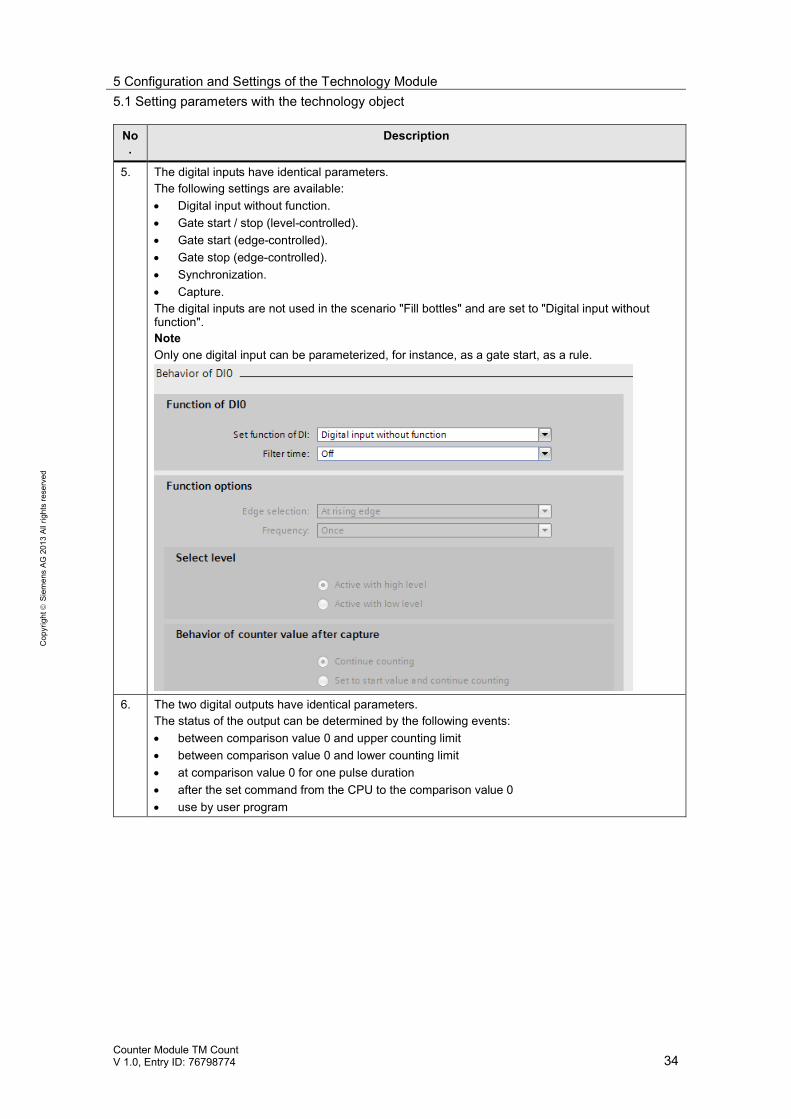
5. The digital inputs have identical parameters.The following settings are available: Digital input without function. Gate start / stop (level-controlled). Gate start (edge-controlled). Gate stop (edge-controlled). Synchronization. Capture.
The digital inputs are not used in the scenario "Fill bottles" and are set to "Digital input withoutfunction".NoteOnly one digital input can be parameterized, for instance, as a gate start, as a rule.
6. The two digital outputs have identical parameters.The status of the output can be determined by the following events: between comparison value 0 and upper counting limit between comparison value 0 and lower counting limit at comparison value 0 for one pulse duration after the set command from the CPU to the comparison value 0 use by user program

5 Configuration and Settings of the Technology Module5.1 Setting parameters with the technology object
Counter Module TM CountV 1.0, Entry ID: 76798774 35
Cop
yrig
htSi
emen
sAG
2013
Allr
ight
sre
serv
ed
No.
Description
7. If the actual encoder value detects a change of direction due to an unsteady or poor encodersignal, this can be compensated by definition of a hysteresis. The value 0 deactivates thehysteresis.
8. You can set the measured value and have the choice between frequency period duration speed
This function is not used in the scenario "Fill bottles" and remains set to the default settings.
5 Configuration and Settings of the Technology Module5.2 Programming: The FB "High_Speed_Counter" (FB1150)
Counter Module TM CountV 1.0, Entry ID: 76798774 36
Cop
yrig
htSi
emen
sAG
2013
Allr
ight
sre
serv
ed
5.2 Programming: The FB "High_Speed_Counter"(FB1150)
5.2.1 Using the technology object
Technology object "High_Speed_Counter"The technology object provides the user not only with a graphical user interface forparameter setting but also a block as a simplified interface to the technologymodule "TM Count". The call interface of the technology object is described inChapter 3.5.
Typical useAfter the parameter setting (Chapter 5.1.2) you can use the FB"High_Speed_Counter" in your user program and also access the individualparameters of the instance DB. This allows you to influence parameters of thetechnology module during operation.
5.2.2 Further parameters FB "High_Speed_Counter" (FB 1150)
OverviewNot all user-programmable parameters are led outside for the technology object"High_Speed_Counter".If you want to change further parameters, e.g. the upper counting limit, you have toaccess the internal static variables of the technology object.
Opening the technology object in the DB editorTo check the further parameters of the FB "High_Speed_Counter" (FB1150) youcan open the technology object in the DB editor.Navigate to the context menu of "[YOUR_PROJECT] > [YOUR_PLC] > Technologyobjects > [YOUR_COUNTER]". Select "Open DB-Editor" there.
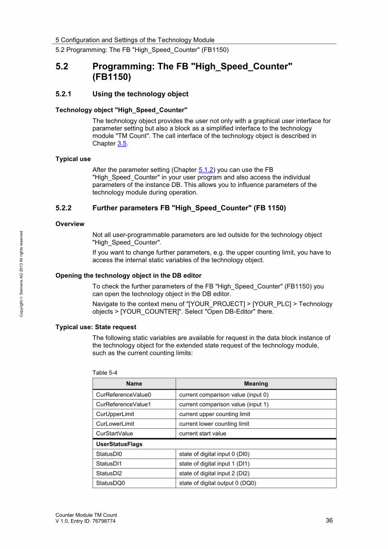
Typical use: State requestThe following static variables are available for request in the data block instance ofthe technology object for the extended state request of the technology module,such as the current counting limits:
Table 5-4
Name Meaning
CurReferenceValue0 current comparison value (input 0)CurReferenceValue1 current comparison value (input 1)CurUpperLimit current upper counting limitCurLowerLimit current lower counting limitCurStartValue current start value
UserStatusFlagsStatusDI0 state of digital input 0 (DI0)StatusDI1 state of digital input 1 (DI1)StatusDI2 state of digital input 2 (DI2)StatusDQ0 state of digital output 0 (DQ0)
5 Configuration and Settings of the Technology Module5.2 Programming: The FB "High_Speed_Counter" (FB1150)
Counter Module TM CountV 1.0, Entry ID: 76798774 37
Cop
yrig
htSi
emen
sAG
2013
Allr
ight
sre
serv
ed
Name Meaning
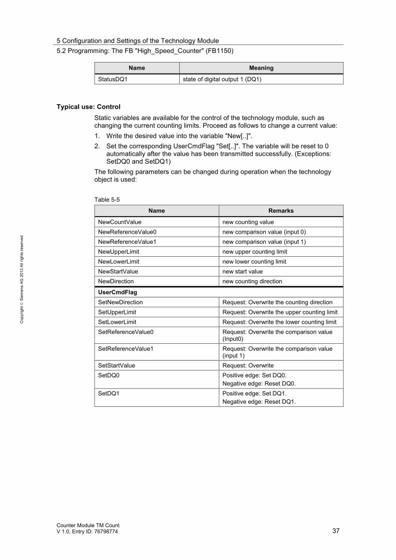
StatusDQ1 state of digital output 1 (DQ1)
Typical use: ControlStatic variables are available for the control of the technology module, such aschanging the current counting limits. Proceed as follows to change a current value:1. Write the desired value into the variable "New[..]".2. Set the corresponding UserCmdFlag "Set[..]". The variable will be reset to 0
automatically after the value has been transmitted successfully. (Exceptions:SetDQ0 and SetDQ1)
The following parameters can be changed during operation when the technologyobject is used:
Table 5-5
Name Remarks
NewCountValue new counting valueNewReferenceValue0 new comparison value (input 0)NewReferenceValue1 new comparison value (input 1)NewUpperLimit new upper counting limitNewLowerLimit new lower counting limitNewStartValue new start valueNewDirection new counting direction
UserCmdFlagSetNewDirection Request: Overwrite the counting directionSetUpperLimit Request: Overwrite the upper counting limitSetLowerLimit Request: Overwrite the lower counting limitSetReferenceValue0 Request: Overwrite the comparison value
(Input0)SetReferenceValue1 Request: Overwrite the comparison value
(input 1)SetStartValue Request: OverwriteSetDQ0 Positive edge: Set DQ0.
Negative edge: Reset DQ0.SetDQ1 Positive edge: Set DQ1.
Negative edge: Reset DQ1.
5 Configuration and Settings of the Technology Module5.3 Setting parameters using HWCN and the data record 128
Counter Module TM CountV 1.0, Entry ID: 76798774 38
Cop
yrig
htSi
emen
sAG
2013
Allr
ight
sre
serv
ed
5.3 Setting parameters using HWCN and the data record128If you do not want to set parameters and program the technology module "TMCount 2x24V" using the technology object "High_Speed_Counter" you can proceedinstead as follows Set parameters in HWCN or change parameters during operation using the data record 128. use the control and feedback interface options for handling the module.
5.3.1 Hardware configuration (HWCN)
Adding the technology module and opening the hardware configurationThe prerequisite for the following steps is a STEP 7 V12 project which has alreadybeen created and an S7-1500 CPU.
Table 5-6
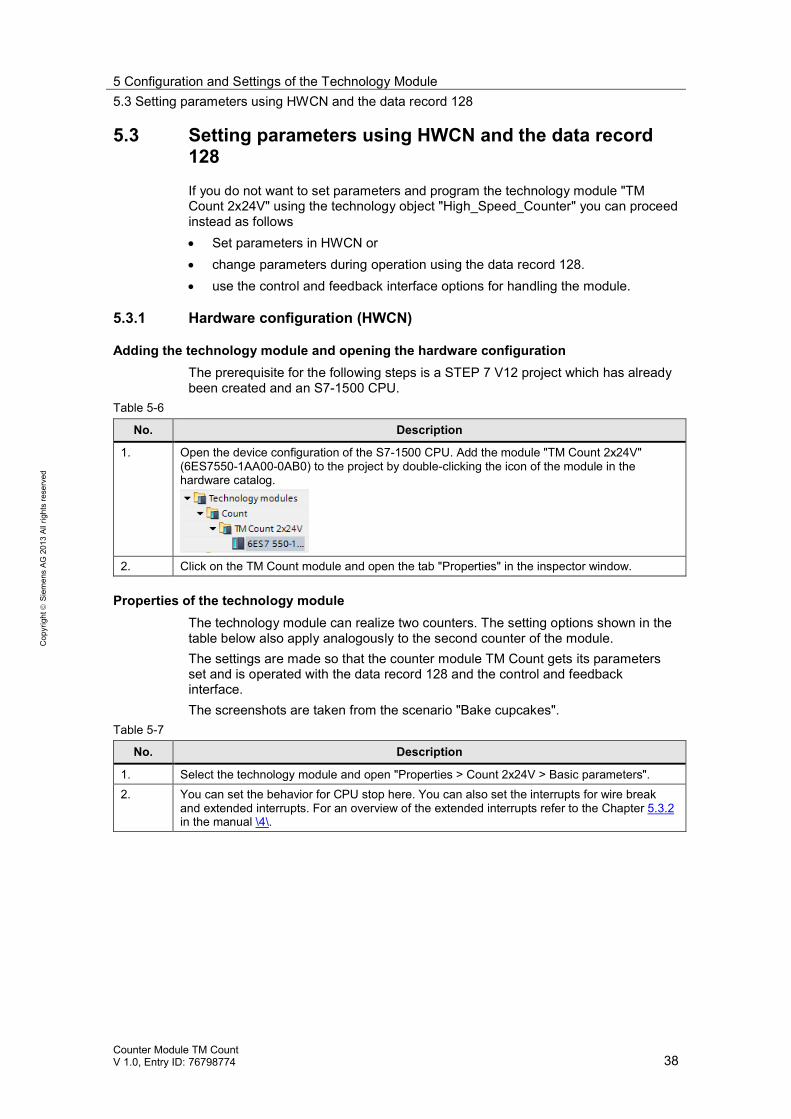
No. Description
1. Open the device configuration of the S7-1500 CPU. Add the module "TM Count 2x24V"(6ES7550-1AA00-0AB0) to the project by double-clicking the icon of the module in thehardware catalog.
2. Click on the TM Count module and open the tab "Properties" in the inspector window.
Properties of the technology moduleThe technology module can realize two counters. The setting options shown in thetable below also apply analogously to the second counter of the module.The settings are made so that the counter module TM Count gets its parametersset and is operated with the data record 128 and the control and feedbackinterface.The screenshots are taken from the scenario "Bake cupcakes".
Table 5-7
No. Description
1. Select the technology module and open "Properties > Count 2x24V > Basic parameters".2. You can set the behavior for CPU stop here. You can also set the interrupts for wire break
and extended interrupts. For an overview of the extended interrupts refer to the Chapter 5.3.2in the manual \4\.
5 Configuration and Settings of the Technology Module5.3 Setting parameters using HWCN and the data record 128
Counter Module TM CountV 1.0, Entry ID: 76798774 39
Cop
yrig
htSi
emen
sAG
2013
Allr
ight
sre
serv
ed
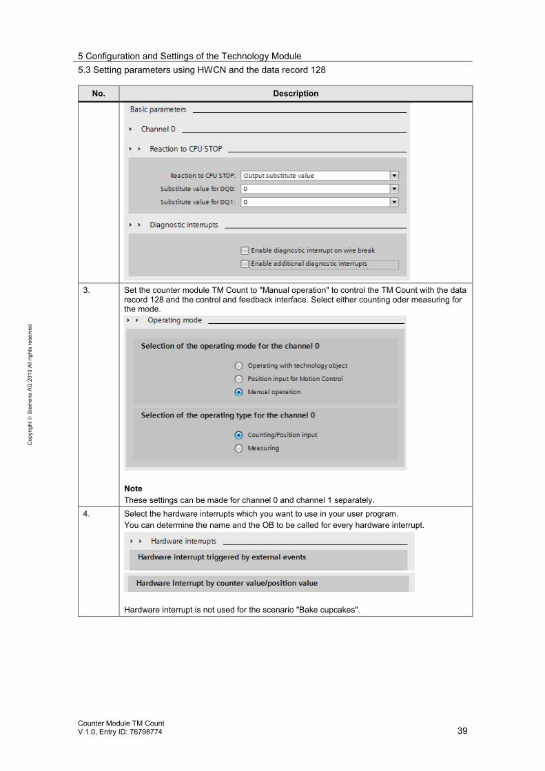
No. Description
3. Set the counter module TM Count to "Manual operation" to control the TM Count with the datarecord 128 and the control and feedback interface. Select either counting oder measuring forthe mode.
NoteThese settings can be made for channel 0 and channel 1 separately.
4. Select the hardware interrupts which you want to use in your user program.You can determine the name and the OB to be called for every hardware interrupt.
Hardware interrupt is not used for the scenario "Bake cupcakes".
5 Configuration and Settings of the Technology Module5.3 Setting parameters using HWCN and the data record 128
Counter Module TM CountV 1.0, Entry ID: 76798774 40
Cop
yrig
htSi
emen
sAG
2013
Allr
ight
sre
serv
ed
No. Description
5. At "I/O addresses" you can set the offset of the input and output addresses of the technologymodule.
6. The "Hardware identifier" is required for setting parameters with the data record 128.
Parameters of the technology moduleIn addition to setting parameters using the data record 128 during operation theparameters can also be set in the hardware configuration (HWCN). The followingtable describes the procedure for the extended parameters. The settings apply tothe scenario "Bake cupcakes".
Table 5-8
No. Description
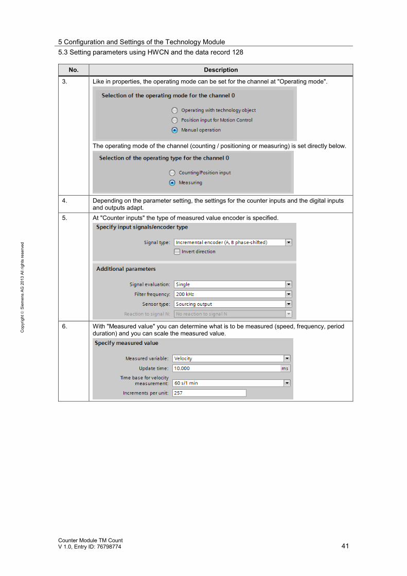
1. In HWCN right-click on the TM. In the context menu, select “Parameters”.
2. As in the properties of the module, the parameters are identical for the channel 0 and thechannel 1, respectively.
5 Configuration and Settings of the Technology Module5.3 Setting parameters using HWCN and the data record 128
Counter Module TM CountV 1.0, Entry ID: 76798774 41
Cop
yrig
htSi
emen
sAG
2013
Allr
ight
sre
serv
ed
No. Description
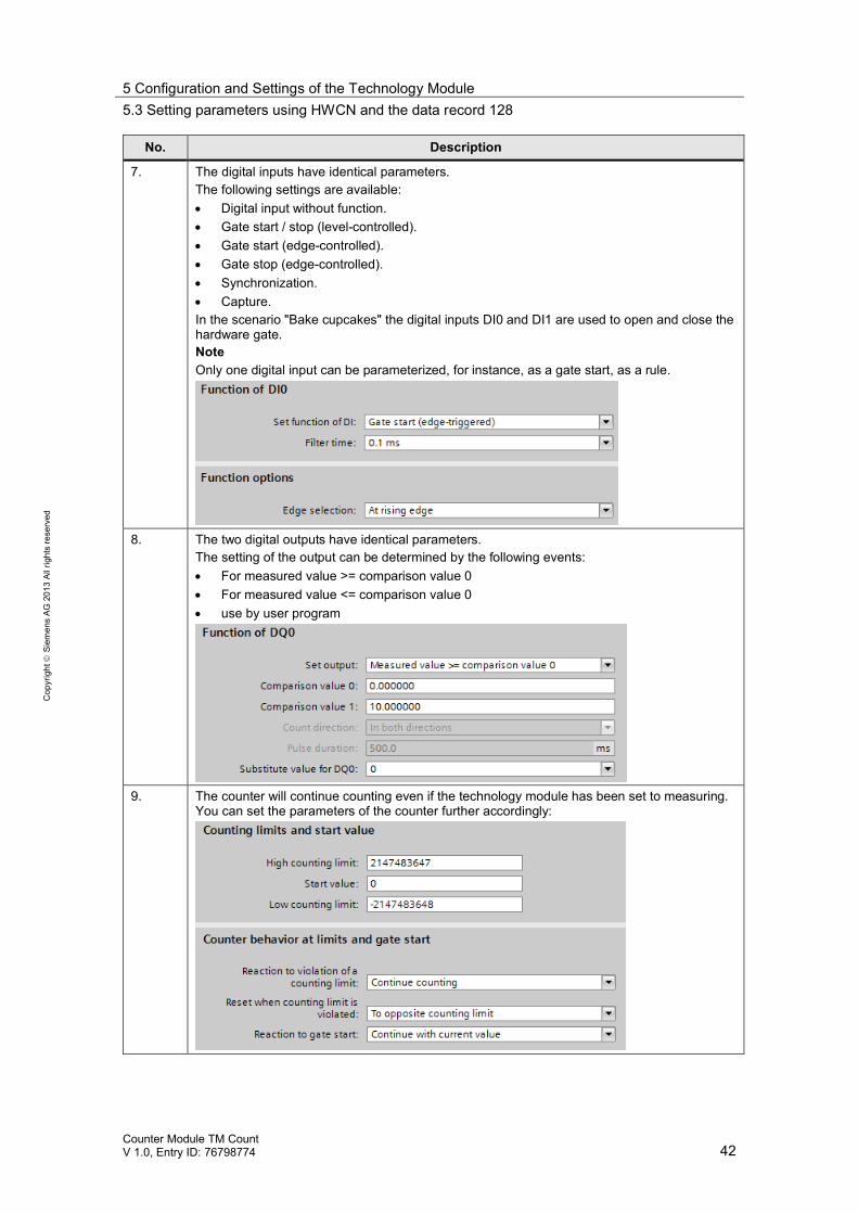
3. Like in properties, the operating mode can be set for the channel at "Operating mode".
The operating mode of the channel (counting / positioning or measuring) is set directly below.
4. Depending on the parameter setting, the settings for the counter inputs and the digital inputsand outputs adapt.
5. At "Counter inputs" the type of measured value encoder is specified.
6. With "Measured value" you can determine what is to be measured (speed, frequency, periodduration) and you can scale the measured value.
5 Configuration and Settings of the Technology Module5.3 Setting parameters using HWCN and the data record 128
Counter Module TM CountV 1.0, Entry ID: 76798774 42
Cop
yrig
htSi
emen
sAG
2013
Allr
ight
sre
serv
ed
No. Description
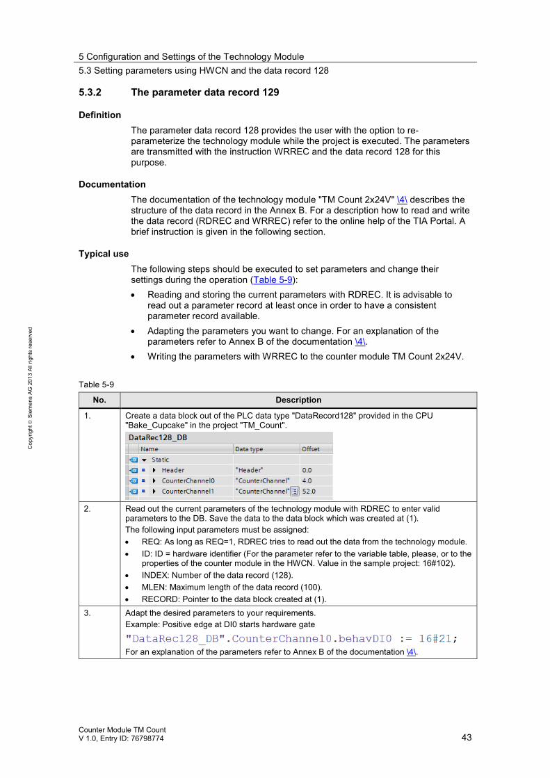
7. The digital inputs have identical parameters.The following settings are available: Digital input without function. Gate start / stop (level-controlled). Gate start (edge-controlled). Gate stop (edge-controlled). Synchronization. Capture.
In the scenario "Bake cupcakes" the digital inputs DI0 and DI1 are used to open and close thehardware gate.NoteOnly one digital input can be parameterized, for instance, as a gate start, as a rule.
8. The two digital outputs have identical parameters.The setting of the output can be determined by the following events: For measured value >= comparison value 0 For measured value <= comparison value 0 use by user program
9. The counter will continue counting even if the technology module has been set to measuring.You can set the parameters of the counter further accordingly:
5 Configuration and Settings of the Technology Module5.3 Setting parameters using HWCN and the data record 128
Counter Module TM CountV 1.0, Entry ID: 76798774 43
Cop
yrig
htSi
emen
sAG
2013
Allr
ight
sre
serv
ed
5.3.2 The parameter data record 129
DefinitionThe parameter data record 128 provides the user with the option to re-parameterize the technology module while the project is executed. The parametersare transmitted with the instruction WRREC and the data record 128 for thispurpose.
DocumentationThe documentation of the technology module "TM Count 2x24V" \4\ describes thestructure of the data record in the Annex B. For a description how to read and writethe data record (RDREC and WRREC) refer to the online help of the TIA Portal. Abrief instruction is given in the following section.
Typical useThe following steps should be executed to set parameters and change theirsettings during the operation (Table 5-9): Reading and storing the current parameters with RDREC. It is advisable to
read out a parameter record at least once in order to have a consistentparameter record available.
Adapting the parameters you want to change. For an explanation of theparameters refer to Annex B of the documentation \4\.
Writing the parameters with WRREC to the counter module TM Count 2x24V.
Table 5-9
No. Description
1. Create a data block out of the PLC data type "DataRecord128" provided in the CPU"Bake_Cupcake" in the project "TM_Count".
2. Read out the current parameters of the technology module with RDREC to enter validparameters to the DB. Save the data to the data block which was created at (1).The following input parameters must be assigned: REQ: As long as REQ=1, RDREC tries to read out the data from the technology module. ID: ID = hardware identifier (For the parameter refer to the variable table, please, or to the
properties of the counter module in the HWCN. Value in the sample project: 16#102). INDEX: Number of the data record (128). MLEN: Maximum length of the data record (100). RECORD: Pointer to the data block created at (1).
3. Adapt the desired parameters to your requirements.Example: Positive edge at DI0 starts hardware gate
For an explanation of the parameters refer to Annex B of the documentation \4\.
5 Configuration and Settings of the Technology Module5.4 Programming: The control and feedback interface
Counter Module TM CountV 1.0, Entry ID: 76798774 44
Cop
yrig
htSi
emen
sAG
2013
Allr
ight
sre
serv
ed
No. Description
4. Write back the processed parameters with WRREC to the technology module. The output"DONE" indicates when the parameter setting has been completed successfully. REQ: As long as REQ=1, WRREC tries to write the data to the technology module. ID: ID = hardware identifier (For the parameter refer to the variable table, please, or to the
properties of the counter module in the HWCN. Value in the sample project: 16#102). INDEX: Number of the data record (128). LEN: Maximum length of the data record; use the value which was indicated at the output
RDREC. RECORD: Pointer to the data block created in (1).
5.4 Programming: The control and feedback interface
Control interfaceThe control interface is used by the user program to influence the behavior of thetechnology module.For a detailed description of the control interface refer to Chapter 4.5 of themanual \5\.
Feedback interfaceThe feedback interface provides the user program with current values and statusinformation of the technology module.For a detailed description of the feedback interface refer to Chapter 4.5 of themanual \5\.
6 Installation6.1 Hardware installation
Counter Module TM CountV 1.0, Entry ID: 76798774 45
Cop
yrig
htSi
emen
sAG
2013
Allr
ight
sre
serv
ed
6 InstallationThis chapter describes how the enclosed TIA Portal project "76798774_TM_Count"is commissioned.
6.1 Hardware installation
Note In order to be able to toggle between both scenarios in the visualization, youneed two CPUs so that the layout with two CPUs is described.
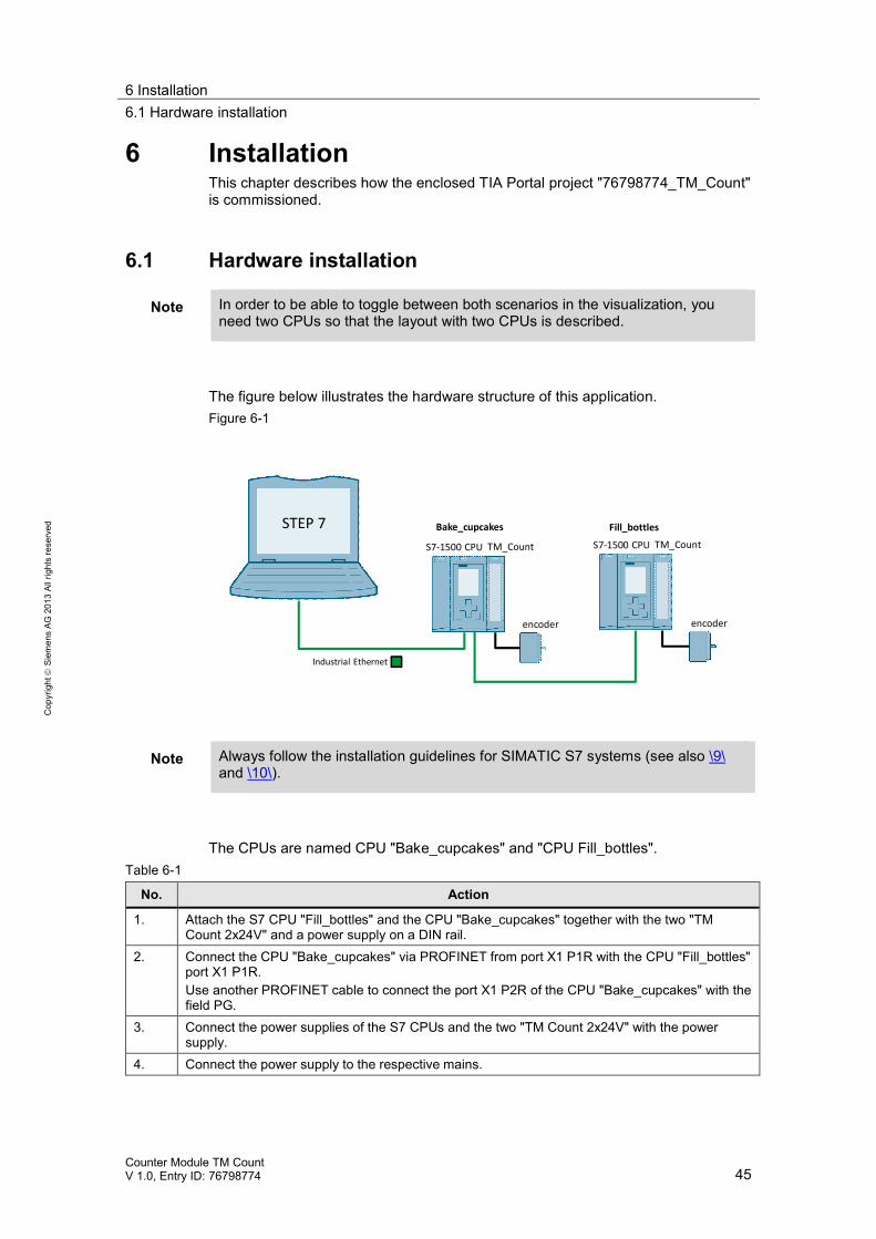
The figure below illustrates the hardware structure of this application.Figure 6-1
STEP 7
Industrial Ethernet
TM_CountS7-1500 CPUTM_CountS7-1500 CPU
encoder encoder
Bake_cupcakes Fill_bottles
Note Always follow the installation guidelines for SIMATIC S7 systems (see also \9\and \10\).
The CPUs are named CPU "Bake_cupcakes" and "CPU Fill_bottles".Table 6-1
No. Action
1. Attach the S7 CPU "Fill_bottles" and the CPU "Bake_cupcakes" together with the two "TMCount 2x24V" and a power supply on a DIN rail.
2. Connect the CPU "Bake_cupcakes" via PROFINET from port X1 P1R with the CPU "Fill_bottles"port X1 P1R.Use another PROFINET cable to connect the port X1 P2R of the CPU "Bake_cupcakes" with thefield PG.
3. Connect the power supplies of the S7 CPUs and the two "TM Count 2x24V" with the powersupply.
4. Connect the power supply to the respective mains.
6 Installation6.2 Software installation
Counter Module TM CountV 1.0, Entry ID: 76798774 46
Cop
yrig
htSi
emen
sAG
2013
Allr
ight
sre
serv
ed
No. Action
5. Set the IP address of the X1 port of the CPUs via the display to the IP addresses used in theexample CPU "Bake_cupcakes": 192.168.0.1 CPU "Fill_bottles": 192.168.0.2
The IP address can be set under "Settings > Addresses >X1 (IE/PN)" in the display.
NoteFor loading to the CPU, the engineering station must be installed in the same subnet.
6. Connect the incremental encoders with the inputs A, B, N, +24VDC and M of the channel 0 ofthe "TM Count 2x24V".
7. At TM Count 2x24 of the CPU "Fill_bottles" connect the inputs 0 and 1 of the channel 0 with therespective hardware (switch, photo sensor, etc.).
Note Using a field PG as engineering station and PC station at the same time isdescribed here.
Alternatively, using a rack PC for visualization is also possible, for instance.
6.2 Software installation
This chapter describes the steps for the installation of the used programs.
Table 6-2 Installation of software components
No. Action Remarks
1. Install STEP 7 Professional V12.0SP1
Note the instructions in the system manual: \3\
2. Install WinCC Professional V12 SP1 Note the instructions in the system manual:\11\
3. Load the sample project"76798774_TM_Count_CODE_v1_0.zip" from the Siemens Online Supportsite.
This entry is accessed via the following link:http://support.automation.siemens.com/WW/view/en/76798774
6.3 Configuring the hardware
Renaming the engineering stationTable 6-3 Renaming the engineering station
No. Action Remarks
1. To load the WinCC Runtime to yourengineering station, the engineering stationmust have the PC name which is used in theproject.
Alternatively, you can adapt the name of the PCstation in the project to your engineering station.
2. Go to the context menu of "Computer" andclick on "Properties". In the following windowclick below "Computer name, domain andworkgroup settings" on "Change settings".
6 Installation6.3 Configuring the hardware
Counter Module TM CountV 1.0, Entry ID: 76798774 47
Cop
yrig
htSi
emen
sAG
2013
Allr
ight
sre
serv
ed
No. Action Remarks
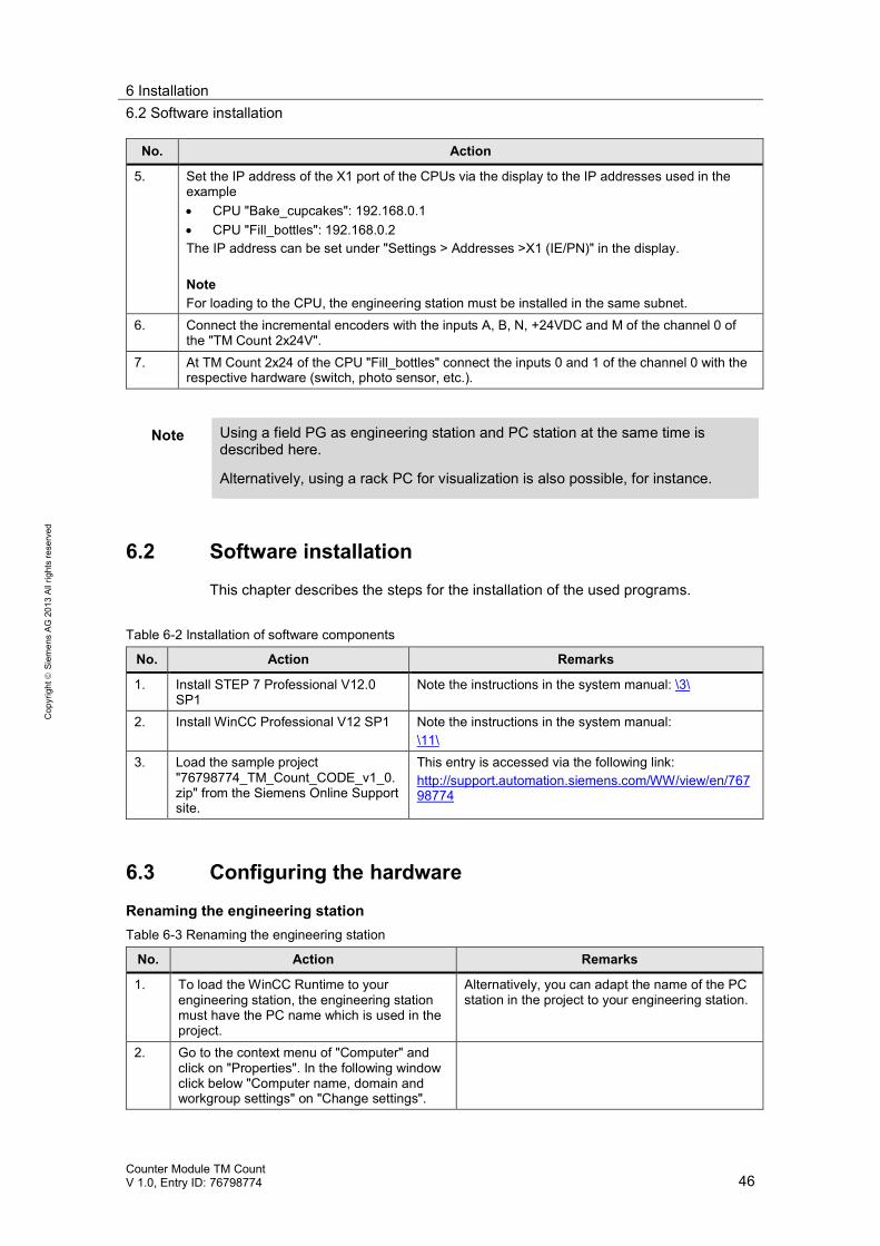
3. In the window "System properties" select"Change" and enter the new computer name"VisuPC" in the respective field then.
4. Confirm and restart your engineering stationto apply the computer name.
Setting the IP address of the engineering stationIf you use the engineering station also as PC station for visualization, you have toassign the specified IP address in the project to the engineering station:
Table 6-4 Assigning the IP address
No. Action Remarks
1. Open the "Network and Sharing Center"2. Click on "Change Adapter Settings" and in the
context menu of your Ethernet adapter select"Properties"
3. Select "Internet Protocol Version 4" andchange the IP address as follows:IP address: 192.168.0.251Subnet mask: 255.255.255.0
4. Confirm the change by clicking on OK.Your engineering station has the same IPaddress now which has also been assigned inthe project "76798774_TM_Count".
5. In addition, set your PG/PC interface ("ControlPanel>Set PG/PC interface") to TCP/IP andthe network adapter which you are using.
Opening and loading the TIA Portal projectTable 6-5
No. Action Remarks
1. Download the file"76798774_TM_Count_CODE_v1_0.zip" toyour engineering station and unzip the folder.
2. In the program folder double-click on the icon"76798774_TM_Count.ap12".The project opens in TIA V12 now.
6 Installation6.3 Configuring the hardware
Counter Module TM CountV 1.0, Entry ID: 76798774 48
Cop
yrig
htSi
emen
sAG
2013
Allr
ight
sre
serv
ed
No. Action Remarks
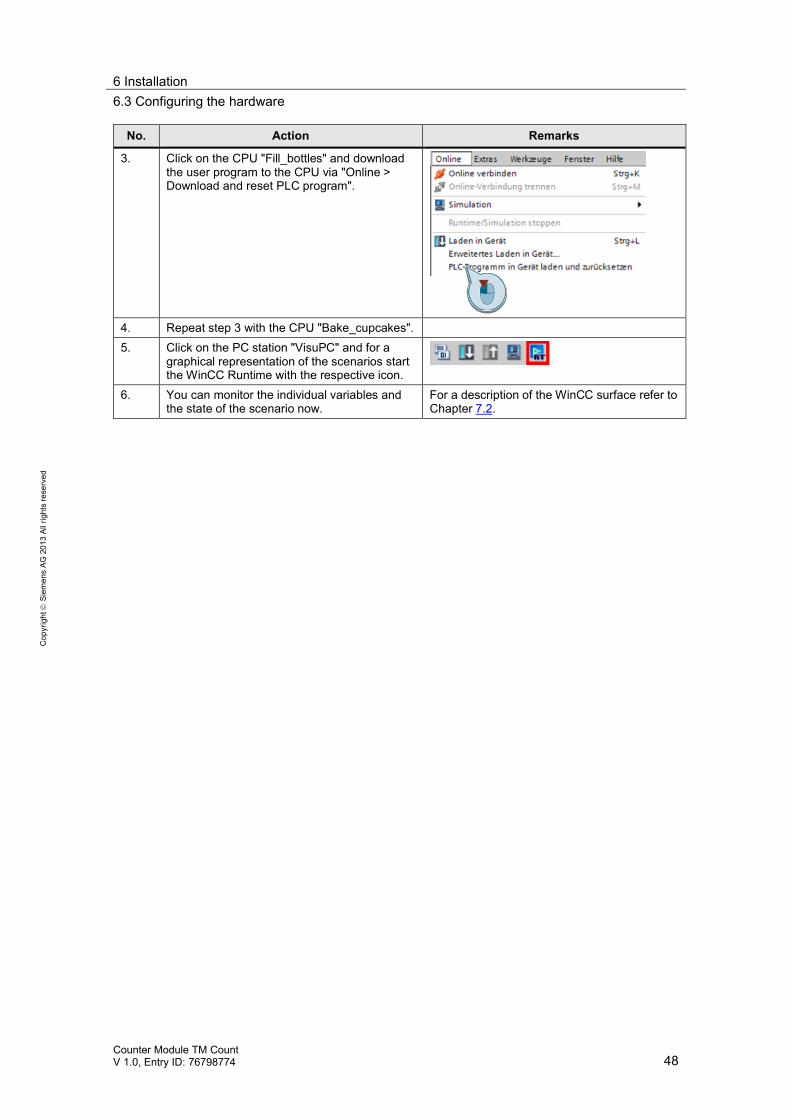
3. Click on the CPU "Fill_bottles" and downloadthe user program to the CPU via "Online >Download and reset PLC program".
4. Repeat step 3 with the CPU "Bake_cupcakes".5. Click on the PC station "VisuPC" and for a
graphical representation of the scenarios startthe WinCC Runtime with the respective icon.
6. You can monitor the individual variables andthe state of the scenario now.
For a description of the WinCC surface refer toChapter 7.2.
7 Operation of the Application7.1 Overview
Counter Module TM CountV 1.0, Entry ID: 76798774 49
Cop
yrig
htSi
emen
sAG
2013
Allr
ight
sre
serv
ed
7 Operation of the Application7.1 Overview
For a better overview of the behavior of the implemented scenarios the user has severaloptions: Insight into the current state of the scenarios via the HMI system WinCC
Runtime Advanced.More detailed insight into further optional variables via the configurable watchtables which have already been prepared in the CPU.
7.2 Operation via the WinCC Runtime
A WinCC Runtime system is running in the PC station "VisuPC" whose start screenallows selecting the two scenarios. If you realize the configuration with only oneCPU, you have to download the other configuration to the CPU for switching over.
7.2.1 Scenario "Fill bottles"
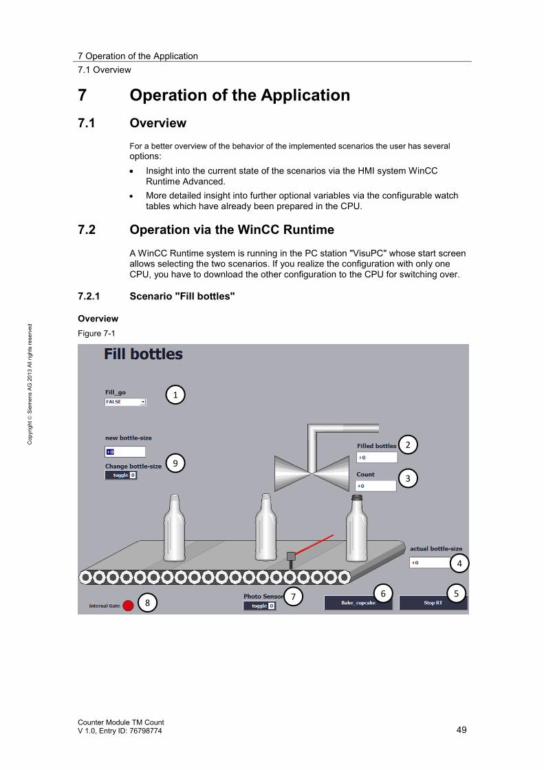
OverviewFigure 7-1
1
6 5
4
3
2
9
78
7 Operation of the Application7.2 Operation via the WinCC Runtime
Counter Module TM CountV 1.0, Entry ID: 76798774 50
Cop
yrig
htSi
emen
sAG
2013
Allr
ight
sre
serv
ed
Table 7-1
Position Remarks
1 The dropdown menu influences the variable Fill_go for triggering the initialization at apositive edge.
2 Indicates how many bottles have been filled since the last initialization.3 Indicates the count value of the bottle which has to be filled now.4 Indicates the current filling quantity of a bottle.5 A click on the button will stop the WinCC Runtime.6 A click on the button will change over to the screen "Bake_cupcakes".7 The dropdown menu is used to specify "TRUE" or "FALSE" for the virtual photo sensor.8 State of the internal gate.9 The I/O field "new bottle-size" is used to specify a new value for the filling quantity of a bottle.
The value of the filling quantity is applied by a positive edge which is created with thedropdown menu.
ProcessThe following table describes the process of the start of the virtual bottling plant,the filling of the first bottles and a change of filling quantity.
Table 7-2
No. Remarks
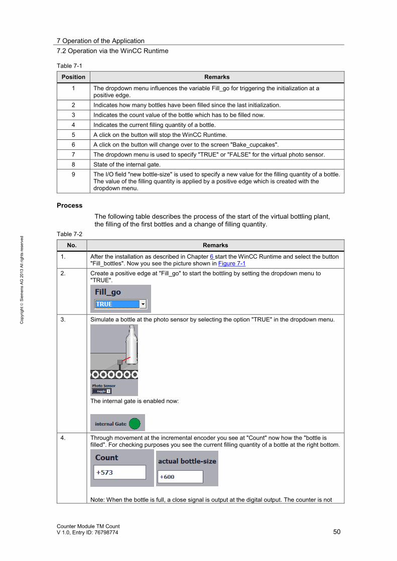
1. After the installation as described in Chapter 6 start the WinCC Runtime and select the button"Fill_bottles". Now you see the picture shown in Figure 7-1
2. Create a positive edge at "Fill_go" to start the bottling by setting the dropdown menu to"TRUE".
3. Simulate a bottle at the photo sensor by selecting the option "TRUE" in the dropdown menu.
The internal gate is enabled now:
4. Through movement at the incremental encoder you see at "Count" now how the "bottle isfilled". For checking purposes you see the current filling quantity of a bottle at the right bottom.
Note: When the bottle is full, a close signal is output at the digital output. The counter is not
7 Operation of the Application7.2 Operation via the WinCC Runtime
Counter Module TM CountV 1.0, Entry ID: 76798774 51
Cop
yrig
htSi
emen
sAG
2013
Allr
ight
sre
serv
ed
No. Remarksstopped. It is assumed that the traversing time of the valve will also cause a "surplus" on thenext bottle and that therefore all bottles will be filled with exactly the same quantity.
5. If you want to change the filling quantity of the bottle enter the new quantity in the input field.Confirm with Return.
Create a positive edge at "Change bottle-size" then (you can still check the current fillingquantity of a bottle at the right lower field "actual bottle-size").
6. In order to open the internal gate of the TM Count again and to count the signals of theincremental encoder again, the initialization has to be repeated with a positive edge at Fill_go.
7 Operation of the Application7.2 Operation via the WinCC Runtime
Counter Module TM CountV 1.0, Entry ID: 76798774 52
Cop
yrig
htSi
emen
sAG
2013
Allr
ight
sre
serv
ed
7.2.2 Scenario "Bake cupcakes"
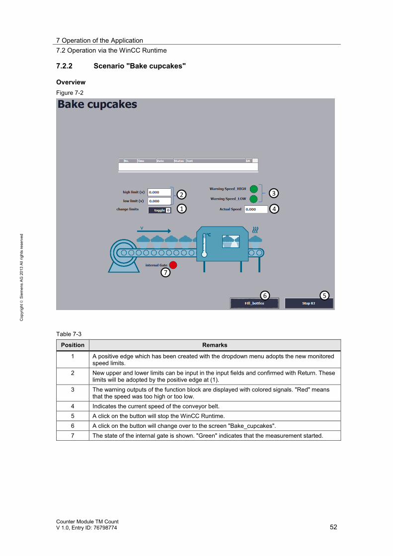
OverviewFigure 7-2
1
3
4
56
2
7
Table 7-3
Position Remarks
1 A positive edge which has been created with the dropdown menu adopts the new monitoredspeed limits.
2 New upper and lower limits can be input in the input fields and confirmed with Return. Theselimits will be adopted by the positive edge at (1).
3 The warning outputs of the function block are displayed with colored signals. "Red" meansthat the speed was too high or too low.
4 Indicates the current speed of the conveyor belt.5 A click on the button will stop the WinCC Runtime.6 A click on the button will change over to the screen "Bake_cupcakes".7 The state of the internal gate is shown. "Green" indicates that the measurement started.
7 Operation of the Application7.2 Operation via the WinCC Runtime
Counter Module TM CountV 1.0, Entry ID: 76798774 53
Cop
yrig
htSi
emen
sAG
2013
Allr
ight
sre
serv
ed
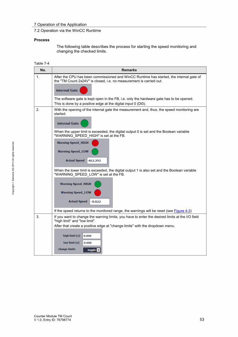
ProcessThe following table describes the process for starting the speed monitoring andchanging the checked limits.
Table 7-4
No. Remarks
1. After the CPU has been commissioned and WinCC Runtime has started, the internal gate ofthe "TM Count 2x24V" is closed, i.e. no measurement is carried out.
The software gate is kept open in the FB, i.e. only the hardware gate has to be opened.This is done by a positive edge at the digital input 0 (DI0).
2. With the opening of the internal gate the measurement and, thus, the speed monitoring arestarted.
When the upper limit is exceeded, the digital output 0 is set and the Boolean variable"WARNING_SPEED_HIGH" is set at the FB.
When the lower limit is exceeded, the digital output 1 is also set and the Boolean variable"WARNING_SPEED_LOW" is set at the FB.
If the speed returns to the monitored range, the warnings will be reset (see Figure 4-3)3. If you want to change the warning limits, you have to enter the desired limits at the I/O field
"high limit" and "low limit".After that create a positive edge at "change limits" with the dropdown menu.
7 Operation of the Application7.3 Monitoring and controlling via the watch tables
Counter Module TM CountV 1.0, Entry ID: 76798774 54
Cop
yrig
htSi
emen
sAG
2013
Allr
ight
sre
serv
ed
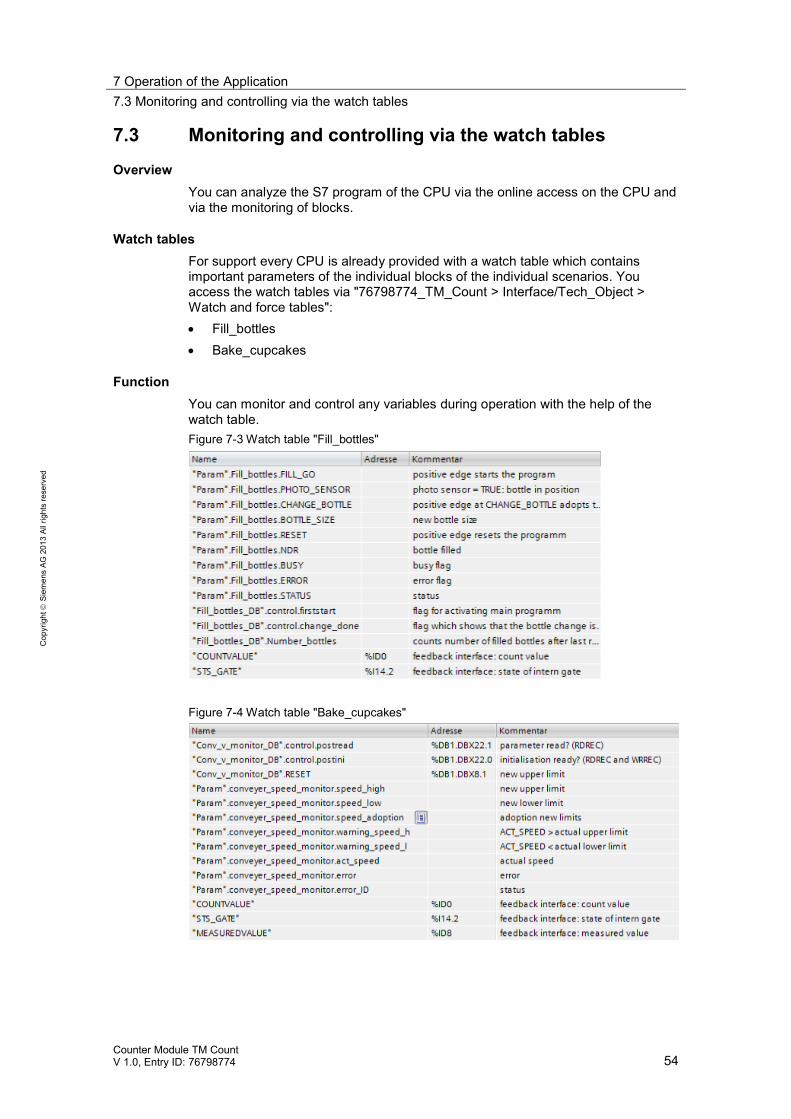
7.3 Monitoring and controlling via the watch tables
OverviewYou can analyze the S7 program of the CPU via the online access on the CPU andvia the monitoring of blocks.
Watch tablesFor support every CPU is already provided with a watch table which containsimportant parameters of the individual blocks of the individual scenarios. Youaccess the watch tables via "76798774_TM_Count > Interface/Tech_Object >Watch and force tables": Fill_bottles Bake_cupcakes
FunctionYou can monitor and control any variables during operation with the help of thewatch table.Figure 7-3 Watch table "Fill_bottles"
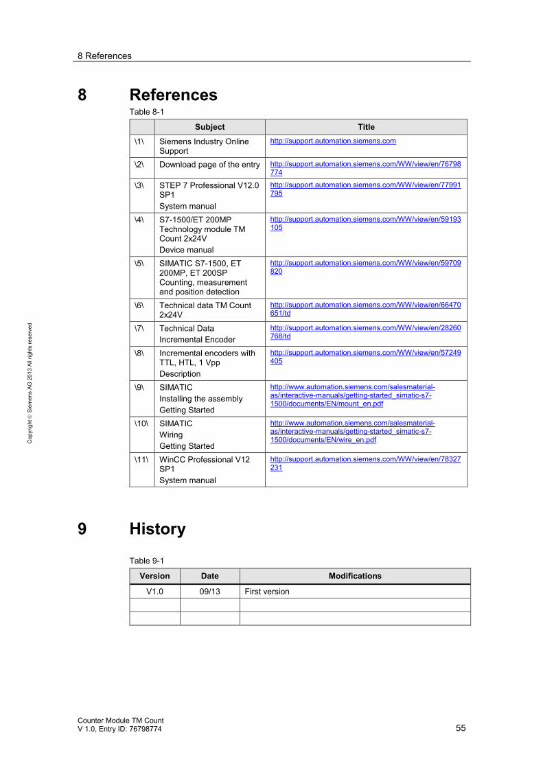
Figure 7-4 Watch table "Bake_cupcakes"
8 References
Counter Module TM CountV 1.0, Entry ID: 76798774 55
Cop
yrig
htSi
emen
sAG
2013
Allr
ight
sre
serv
ed
8 ReferencesTable 8-1
Subject Title
\1\ Siemens Industry OnlineSupport
http://support.automation.siemens.com
\2\ Download page of the entry http://support.automation.siemens.com/WW/view/en/76798774
\3\ STEP 7 Professional V12.0SP1System manual
http://support.automation.siemens.com/WW/view/en/77991795
\4\ S7-1500/ET 200MPTechnology module TMCount 2x24VDevice manual
http://support.automation.siemens.com/WW/view/en/59193105
\5\ SIMATIC S7-1500, ET200MP, ET 200SPCounting, measurementand position detection
http://support.automation.siemens.com/WW/view/en/59709820
\6\ Technical data TM Count2x24V
http://support.automation.siemens.com/WW/view/en/66470651/td
\7\ Technical DataIncremental Encoder
http://support.automation.siemens.com/WW/view/en/28260768/td
\8\ Incremental encoders withTTL, HTL, 1 VppDescription
http://support.automation.siemens.com/WW/view/en/57249405
\9\ SIMATICInstalling the assemblyGetting Started
http://www.automation.siemens.com/salesmaterial-as/interactive-manuals/getting-started_simatic-s7-1500/documents/EN/mount_en.pdf
\10\ SIMATICWiringGetting Started
http://www.automation.siemens.com/salesmaterial-as/interactive-manuals/getting-started_simatic-s7-1500/documents/EN/wire_en.pdf
\11\ WinCC Professional V12SP1System manual
http://support.automation.siemens.com/WW/view/en/78327231
9 History
Table 9-1
Version Date Modifications
V1.0 09/13 First version


![g*tm /mR sU] - Hindu · PDF filemaharishi university of management. g*tm /mr su] maharishi university of management. maharishi university of management. maharishi university of management](https://img.pdfslide.us/doc/110x75/5aa91fbf7f8b9a81188c6353/gtm-mr-su-hindu-maharishi-university-of-management-gtm-mr-su-maharishi.jpg)