Embed Size (px)
DESCRIPTION
dsd
Citation preview

Dell Technical Marketing – Data Center Networking June 2013
Dell Networking S5000:
Deployment of a Converged Infrastructure with FCoE
Deployment/Configuration Guide

Dell Networking S5000: Deployment of a Converged Infrastructure with FCoE
2 Deployment of a Converged Infrastructure with FCoE Deployment/Configuration Guide
This document is for informational purposes only and may contain typographical errors. The content is provided as is, without express or implied warranties of any kind.
© 2013 Dell Inc. All rights reserved. Dell and its affiliates cannot be responsible for errors or omissions in typography or photography. Dell, the Dell logo, and PowerEdge are trademarks of Dell Inc. Intel and Xeon are registered trademarks of Intel Corporation in the U.S. and other countries. Microsoft, Windows, and Windows Server are either trademarks or registered trademarks of Microsoft Corporation in the United States and/or other countries. Other trademarks and trade names may be used in this document to refer to either the entities claiming the marks and names or their products. Dell disclaims proprietary interest in the marks and names of others.
June 2013 | Rev 1.2

Dell Networking S5000: Deployment of a Converged Infrastructure with FCoE
3 Deployment of a Converged Infrastructure with FCoE Deployment/Configuration Guide
Contents Overview ................................................................................................................. 4
A: Converged Network Solution - Dell PowerEdge Server, Dell Compellent storage array, and Dell S5000 as NPIV Proxy Gateway ..................................................................................... 4
B: Converged Network Solution - Dell PowerEdge Server, Dell PowerVault storage array, and Dell S5000 as NPIV Proxy Gateway ................................................................................... 32
C: Using Dell S4810 or Dell MXL Blade switch as a FIP-snooping Bridge................................ 55
D: FCoE CNA adapter configuration specifics .................................................................... 59
Broadcom BCM57810S ............................................................................................. 59
Creating a NIC Team ............................................................................................ 62
Dell QLogic QLE8262 .............................................................................................. 68
Creating a NIC Team ............................................................................................ 70

Dell Networking S5000: Deployment of a Converged Infrastructure with FCoE
4 Deployment of a Converged Infrastructure with FCoE Deployment/Configuration Guide
Overview In the “Dell Networking S5000: The Building Blocks of Unified Fabric and LAN/SAN Convergence” whitepaper we demonstrated and explained the movement from a traditional non-converged LAN/SAN network to a converged LAN/SAN infrastructure and how the Dell S5000 switch is an ideal solution for this transition. In addition, we covered the many benefits of moving to a converged infrastructure such as less maintenance and considerable cost savings. The Dell S5000 converged switch with its unique modular design allows end users to migrate to a converged solution and increase port count at their own pace without replacing the entire switch. This benefit is unmatched in the industry. In this whitepaper we cover detailed Dell S5000 topology and configuration examples.
A: Converged Network Solution - Dell PowerEdge Server, Dell Compellent storage array, and Dell S5000 as NPIV Proxy Gateway We will first demonstrate a non-converged setup and then add the Dell S5000 to the picture. This will allow us to see how the connections and configuration change from a traditional non-converged environment to a converged environment with the introduction of the Dell S5000 switch. You’ll be surprised how easy the setup is and how the backend LAN and SAN can remain untouched.
The traditional LAN/SAN non-converged setup example is shown below in Figure 1. As you can see, a Dell PowerEdge R720 server with a 2-port FC HBA is used to connect to two FC switches which are then connected to a Dell Compellent storage array composed of two SC8000 controllers and one SC220 enclosure. Each FC port is connecting to a different fabric. Windows Server 2008 R2 Enterprise is installed on the server.
In the below setup, the LAN side will be the usual setup with either an active/standby or active/active configuration up to separate ToR Dell S4810 switches which have VLT employed up to the core Z9000 switches.
For the below diagram I’ll focus in on the SAN configuration.

Dell Networking S5000: Deployment of a Converged Infrastructure with FCoE
5 Deployment of a Converged Infrastructure with FCoE Deployment/Configuration Guide
Figure 1: Traditional LAN/SAN non-converged network
The Dell Compellent Storage Center controllers are used to support various I/O adapters including FC, iSCSI, FCoE, and SAS. A Dell Compellent Storage Center consists of one or two controllers, FC switches, and one or more enclosures. In the above example, two Compellent SC8000 controllers, one Compellent SC220 enclosure, two FC switches, and one 4-port FC HBA card on each Compellent controller is used for the SAN network. The FC switches provide robust connectivity to servers, allowing for the use of multiple controllers and redundant transport paths.
SAS enclosures hold disks for data storage and connect to the controllers through back-end ports via SAS cables; you can see how the SC220 enclosure and controllers are cabled together in Figure 1 above.
To keep the diagram uncluttered yet detailed, the only connections not shown are the ‘eth0’ ports on each controller connecting to the management network and the ‘eth1’ port on each controller connecting to the ‘eth1’ port on the other controller. The ‘eth0’ connection supports system login and access for the software. It’s used to send emails, alerts, SNMP traps, and Phone Home data. The ‘eth1’ connection is used for dedicated Inter-Process Communication (IPC) between controllers in a dual-controller Storage Center. There is no default gateway for ‘eth1’ and it does not need to be set. See the “CT-SC040 and SC8000 Connectivity Guide” and “Compellent Storage Center System Setup Guide” to get started on cabling and configuring your Compellent storage array.
In this example setup, two SC8000 controllers and one SC220 disk enclosure have been cabled together. There are two paths available from the server to the FC switches and four paths available from each FC switch to the Compellent storage array. Compellent SC8000 Load Balancing Policy Options: The Compellent SC8000 controller uses Microsoft Multipath I/O (MPIO) for load balancing over ports.

Dell Networking S5000: Deployment of a Converged Infrastructure with FCoE
6 Deployment of a Converged Infrastructure with FCoE Deployment/Configuration Guide
Microsoft MPIO is a framework that allows administrators to configure load balancing and failover processes for FC and iSCSI connected storage devices. You can configure load balancing to use up to 32 independent paths from the connected storage devices. The MPIO framework uses Device Specific Modules (DSM) to allow path configuration. For Windows Server 2008 and above, Microsoft provides a built-in generic Microsoft DSM (MSDSM) and it should be used. For Windows Server 2003 only, Dell Compellent provides a DSM.
A load balance policy is used to determine which path is used to process I/O. Once the Compellent
volume has been created and mapped accordingly as will be demonstrated shortly, to see the selected
MPIO policy in Windows Server 2008 R2 Enterprise navigate to ‘Start->Administrative Tools-
>Computer Management’. On the left-hand pane navigate to ‘Computer Management->Storage->Disk
Management’ and right click the disk created on the Compellent storage array and select ‘Properties’.
Next, select the ‘Hardware’ tab, click the ‘Properties’ button at the bottom right, and select the ‘MPIO’
tab. Figure 2 below displays what you should see. Note that the default will be “Round Robin”.
Figure 2: Checking MPIO settings in Windows Server 2008 R2 Enterprise
Additionally, there are two IO connection options available with the Dell Compellent Storage Center
that allow multiple paths to be presented to the servers: ‘Legacy Ports’ and ‘Virtual Ports’. You will be
asked which one you would like to use when initially setting-up the Compellent Storage Center and
configuring the FC IO cards. See the “Storage Center 6.2 System Setup Guide” for more information
on initial setup of the Dell Compellent Storage Center.
In legacy mode, front-end IO ports (in this case FC ports) are broken into primary and reserve ports
based on a fault domain. The reserve port is in a standby mode until a primary port fails over to the

Dell Networking S5000: Deployment of a Converged Infrastructure with FCoE
7 Deployment of a Converged Infrastructure with FCoE Deployment/Configuration Guide
reserve port. In terms of MPIO, this requires twice the IO ports to enable multiple paths. For
redundancy, a primary port connects to one controller, and the reserved port in that fault domain
connects to the other controller. While this is a highly robust failover solution, it requires a large
number of ports.
Dell Compellent introduced virtual ports in Storage Center 5.0. Virtual ports allow all front-end IO
ports to be virtualized. All FC ports can be used at the same time for load balancing as well as failover
to another port. Although a virtual disk can still only be written to from the controller that owns the
disk, virtual ports allow for better performance in terms of failover as the virtual connection can simply
be moved to another physical port in the same fault domain. To use virtual ports all FC switches and
HBAs must support N_Port ID Virtualization (NPIV). See the “Dell Compellent Storage Center Microsoft
Multipath IO (MPIO) Best Practices Guide” for more information on multipathing with Microsoft
Windows 2008 R2 Enterprise.
The two FC switches I am using are Brocade 6505s and the zoning configurations are below. The WWPNs starting with ‘10’ are the FC HBA WWPNs and the other WWPNs are for the Compellent storage array.
During initial configuration of the Compellent Storage Center, we created a disk pool labeled “Pool_1” consisting of seven 300 GB drives. The total disk space is 1.64 TB; this can be seen in the screen shot of the Storage Center System Manager GUI as shown below in Figure 5.
Figure 3: Zoning for fabric A FC switch
Figure 4: Zoning for fabric B FC switch
> zonecreate financeServer1_p1_test,"10:00:8c:7c:ff:30:7d:28;50:00:d3:10:00:ed:b2:3d;50:00:d3:10:00:ed:b2:43; 50:00:d3:10:00:ed:b2:3b;50:00:d3:10:00:ed:b2:41" > cfgcreate zoneCfg_test,"financeServer1_p1_test" > cfgenable zoneCfg_test > cfgsave
> zonecreate financeServer1_p2_test,"10:00:8c:7c:ff:30:7d:29;50:00:d3:10:00:ed:b2:3c;50:00:d3:10:00:ed:b2:42; 50:00:d3:10:00:ed:b2:3a;50:00:d3:10:00:ed:b2:40" > cfgcreate zoneCfg_test,"financeServer1_p2_test" > cfgenable zoneCfg_test > cfgsave

Dell Networking S5000: Deployment of a Converged Infrastructure with FCoE
8 Deployment of a Converged Infrastructure with FCoE Deployment/Configuration Guide
Figure 5: Storage Center System Manager GUI displays disk pool “Pool_1” with 1.64 TB Free space
Since we have two fabrics, fabric A and fabric B, we create two fault domains. Domain 1 is already
created by default and all the FC ports are currently in domain 1. To create another domain click
‘Storage Management’ on the top left of the webpage and then select ‘System->Setup->Configure
Local Ports’. Next, click the ‘Edit Fault Domains’ button at the bottom right of the dialog box. On the
next dialog box click the ‘Create Fault Domain’ button on the lower right of the dialog box. In the
‘Name’ field type a name for the new domain. In this case, we used “Domain 2”. Make sure ‘FC’ is
selected in the ‘Type’ field and click ‘Continue’. Figure 6 below shows that we have already created the
second domain.
Figure 6: Creating an additional Fault Domain on Compellent Storage Array
Now we can navigate back to the ‘Configure Local Ports’ dialog and select the appropriate Domain to
put each port in. Each fabric should be in its own Domain; we put all ports going to fabric A in Domain
1 and all ports going to fabric B in Domain 2 as shown below.

Dell Networking S5000: Deployment of a Converged Infrastructure with FCoE
9 Deployment of a Converged Infrastructure with FCoE Deployment/Configuration Guide
Figure 7: Assigning ports on Compellent Storage to respective Fault Domains
If you get a warning that paths are not balanced, navigate to the left-hand pane, right click
‘Controllers’ and select ‘Rebalance Local Ports’.
Next, a server object needs to be created and the respective FC ports have to be selected to be used
by the server object. This can be accomplished by right clicking ‘Servers’ on the left pane and selecting
‘Create Server’. In Figure 8 below, you can see a server object named “Finance_Server” was created
that includes both of the FC ports on the FC HBA card.
Figure 8: Added Dell PowerEdge Server HBAs to ‘Server Object’ on Dell Compellent Storage Array
The next step is to enable mulipathing on Windows Server 2008 R2 Enterprise. Navigate to
‘Start->Administrative Tools->Server Manager->Features->Add Features’ and select ‘Multipath I/O’.
You can see in Figure 9 below that we have already installed the ‘Multipath I/O’ feature.

Dell Networking S5000: Deployment of a Converged Infrastructure with FCoE
10 Deployment of a Converged Infrastructure with FCoE Deployment/Configuration Guide
Figure 9: Installing Windows Server 2008 R2 Enterprise Multipath I/O feature
Now navigate to ‘Start->Control Panel->MPIO’ and click the ‘Add’ button. When prompted for a
‘Device Hardware ID’, input “COMPELNTCompellent Vol” and click the ‘OK’ button. The system will
need to be restarted for the changes to take effect. Figure 10 displays the “COMPELNTCompellent Vol”
text that you should see on the MPIO Devices tab in ‘MPIO Properties’ once the system is brought
back up.

Dell Networking S5000: Deployment of a Converged Infrastructure with FCoE
11 Deployment of a Converged Infrastructure with FCoE Deployment/Configuration Guide
Figure 10: Installing Windows Server 2008 R2 Enterprise Multipath I/O for Compellent array
Next, create a volume and map it to a server object so the respective server can write to the FC
storage array. Simply right click ‘Volumes’ on the left-hand pane and select ‘Çreate Volume’ to get
started. During the process, you will be asked to select a ‘Replay Profile’; this is simply asking you how
often ‘snapshots/recovery points’ of the storage volume should be taken. A ‘snapshot/recovery point’
allows you to revert a volume back to a certain point in time (for example if files are accidentally
deleted). In Figure 11 below, you can see that a 20 GB volume named “Finance_Data_Compellent” has
already been created. Figure 12 displays the dialog box where you can select a ‘Replay Profile’.

Dell Networking S5000: Deployment of a Converged Infrastructure with FCoE
12 Deployment of a Converged Infrastructure with FCoE Deployment/Configuration Guide
Figure 11: Created 20 GB “Finance_Data_Compellent” volume on Compellent array

Dell Networking S5000: Deployment of a Converged Infrastructure with FCoE
13 Deployment of a Converged Infrastructure with FCoE Deployment/Configuration Guide
Figure 12: Confirming to keep the default value for ‘Replay Profiles’
The last step in configuring the Dell Compellent Storage Center array is mapping the newly created
volume to the server. Once you create the volume, you will be asked if you want to map it to a server
object. You can do it at this time or later. If mapping the volume to a server object later, on the left-
hand pane under ‘Storage->Volumes’, simply right click on the volume you just created and select
‘Map Volume to Server’. You can then select the respective server object that you created prior.
As soon as the HBA on the Windows server detects storage available for it, it will be detected in the
Windows disk management administration tool after performing a disk scan. To perform a disk scan,
right click ‘Disk Management’ on the left-hand pane and select ‘Rescan Disks’. You must right click the
detected virtual disk and initialize it. Below in Figure 13, you can see we have already initialized the disk
(Disk 1) and formatted it as NTFS.

Dell Networking S5000: Deployment of a Converged Infrastructure with FCoE
14 Deployment of a Converged Infrastructure with FCoE Deployment/Configuration Guide
Figure 13: Initialized and formatted virtual disk within Windows Server 2008 R2 Enterprise
Now the volume on the Compellent storage array displays in Windows just like a typical hard drive.
Note, no special configuration was needed on the HBA.
Figure 14: Remote storage on Compellent as seen in Windows as drive ‘T:’

Dell Networking S5000: Deployment of a Converged Infrastructure with FCoE
15 Deployment of a Converged Infrastructure with FCoE Deployment/Configuration Guide
To observe that the storage ports and HBA ports are logged into the fabric, you can use the ‘nsshow’ command on the Brocade FC switch as shown below in Figure 15. Note that since the command is run on the fabric A FC switch, only eight storage ports and one host FC HBA port is logged into the fabric as expected. The reason we see eight storage ports instead of four is because we are using virtual port mode on the Dell Compellent array so we are seeing the physical WWPN and the virtual WWPN. We would see similar (with different WWPNs) on the fabric B FC switch.

Dell Networking S5000: Deployment of a Converged Infrastructure with FCoE
16 Deployment of a Converged Infrastructure with FCoE Deployment/Configuration Guide
Figure 15: Node logins on the fabric A FC switch
You can also see the node WWPN by looking at what is logged in on the physical port as shown in Figure 16 below.

Dell Networking S5000: Deployment of a Converged Infrastructure with FCoE
17 Deployment of a Converged Infrastructure with FCoE Deployment/Configuration Guide
Figure 16: Check WWPNs logged in on port 2 of fabric A FC switch
We can use the respective port WWPNs to create a specific zoning configuration such as that displayed below in Figure 17.
Figure 17: Zoning configuration created on fabric A FC switch
On the fabric A FC switch you can see the WWPN of the server HBA port is ‘10:00:8c:7c:ff:30:7d:28’
and the WWPNs of the storage ports are ‘50:00:d3:10:00:ed:b2:3d’, ‘50:00:d3:10:00:ed:b2:43,

Dell Networking S5000: Deployment of a Converged Infrastructure with FCoE
18 Deployment of a Converged Infrastructure with FCoE Deployment/Configuration Guide
‘50:00:d3:10:00:ed:b2:3b’, and ‘50:00:d3:10:00:ed:b2:41’. This zoning configuration is allowing all four
storage ports to communicate only to each other and the server FC HBA node.
On the fabric B FC switch you can see the WWPN of the server HBA port is ‘10:00:8c:7c:ff:30:7d:28’ and the WWPNs of the storage ports are ‘50:00:d3:10:00:ed:b2:3c’, ‘50:00:d3:10:00:ed:b2:42’, ‘50:00:d3:10:00:ed:b2:3a’, and ‘50:00:d3:10:00:ed:b2:40’.
Another useful FC switch command to check what ports are connected is ‘switchshow’. Figure 18: ‘switchshow’ command on fabric A FC switch displaying connections on FC ports
As you can see in Figure 18 above, since we are using virtual port mode on the Dell Compellent
storage array, instead of the normal F_Port text as shown on port 2 which is connected to the FC HBA
on the server, we see “1 N Port + 1 NPIV public”. In this case the F_Port is actually a VF_Port and the
N_Port is actually a NV_Port.
Note, both controllers on the Compellent storage array are active and each fabric has two paths to controller A and two paths to controller B. They are all logged into the fabric. Unlike in legacy mode, with virtual port mode, a virtual connection from a VN_Port can fail over to another physical port in the same domain as long as the port being failed over to is on the controller that is the primary controller for the volume. In legacy mode, in this case, four ports would be reserved for failover. See

Dell Networking S5000: Deployment of a Converged Infrastructure with FCoE
19 Deployment of a Converged Infrastructure with FCoE Deployment/Configuration Guide
Compellent documentation for more information on Compellent configuration.
Adding the Dell S5000 Converged Switch to the Topology
In Figure 19, you can see how the traditional non-converged topology has changed with the
introduction of the Dell S5000 switch in a possible use case. Note how the Dell S4810 Ethernet
switches have been replaced by Dell S5000 converged switches. Also, note how the separate Ethernet
NIC and FC adapters on the server have been replaced by one converged network adapter (CNA). FC
frames are now encapsulated in Ethernet frames and both LAN and SAN traffic are carried over the
same Ethernet links up to the Dell S5000 which separates the two different types of traffic. For
different possible use cases of the Dell S5000, see the “Dell Networking S5000: Data Center ToR
Architecture and Design” document.
Figure 19: Dell S5000 acting as a NPIV Proxy Gateway and allowing for a converged infrastructure
It’s important to note that as long as the appropriate drivers for both FC and Ethernet are installed, the operating system can see two CNA ports as multiple Ethernet ports and FC HBA ports if NIC partitioning (NPAR) is employed. Figure 20 displays how Windows logically sees a CNA card with two ports with NPAR and FCoE Enabled as a 2-port NIC and a 2-port FC HBA.

Dell Networking S5000: Deployment of a Converged Infrastructure with FCoE
20 Deployment of a Converged Infrastructure with FCoE Deployment/Configuration Guide
Figure 20: Windows view in Device Manager of one Dell QLogic QLE8262 CNA with NPAR and FCoE enabled
As in the traditional non-converged setup, the LAN side will be the usual setup with either an active/standby or active/active configuration up to separate ToR Dell S5000 switches which have VLT employed up to the core Z9000 switches. The difference here is that the Ethernet ports connecting up to the ToR are virtual ports.
The Dell PowerEdge R720 server has its virtual Ethernet NICs configured via NIC teaming and connecting to two separate Dell S5000 switches. The virtual HBA ports are connecting to the same Dell S5000 switches but are logically separated from the Ethernet NICs and the NIC teaming configuration is not taken into account.
Figure 21: Logical view of how operating system sees CNA with NPAR and FCoE enabled
Since we are using a Dell QLogic QLE8262 CNA, the first thing we need to do is configure it for FCoE. Note, since we NIC team with ‘Switch Independent Load Balancing’, no configuration is required on the S5000 switches and the switches are not aware of the NIC team. See the “Dell QLogic QLE8262” section in section D: “FCoE CNA adapter configuration specifics” for details of the configuration.
As no change is required on the backend LAN/SAN networks except for some zoning/access controls, the main task in the new topology is the configuration of the Dell S5000’s switches for both fabric A and fabric B. This configuration is shown below in Figure 22 and Figure 23.

Dell Networking S5000: Deployment of a Converged Infrastructure with FCoE
21 Deployment of a Converged Infrastructure with FCoE Deployment/Configuration Guide
Configuration steps:
1. Create the LACP LAG up to the VLT
2. Configure port to the CNA as a hybrid port. Create a LAN VLAN and tag it to both the ‘tengigabitethernet 0/12’ interface going to the respective CNA and port channel going up to VLT.
3. Enable FC capability
4. Create DCB Map and configure the priority-based flow control (PFC) and enhanced transmission selection (ETS) settings for LAN and SAN traffic. Priorities are mapped to priority groups using the ‘priority-pgid’ command. In this example, priorities 0, 1, 2, 4, 5, 6, and 7 are mapped to priority group 0. Priority 3 is mapped to priority-group 1.
5. Create FCoE VLAN
6. Next, create a FCoE MAP so FCoE traffic is mapped to the respective VLAN. The FCoE MAP is applied to both ‘tengigabitethernet 0/12’ interface going to the respective CNA port and to the FC interface connecting to the FC switch. Note, on S5000, FCoE is always mapped to priority 3.
7. Apply DCB map to downstream interface going to server. The same procedure is repeated for the S5000 connecting to fabric B. Note that we used a different ‘fc-map’ and FCoE VLAN. Since fabric A and fabric B are isolated from each other, this was not necessary, however, it may be easier to troubleshoot and understand if some distinction is made between the two fabrics. Especially important to note is the fact that the same Ethernet port on the S5000 where the FCoE MAP is applied is also untagged on the default VLAN. This is needed because the FIP protocol communicates over the default VLAN to discover the FCoE VLAN. The LAN traffic is tagged on VLAN 5.

Dell Networking S5000: Deployment of a Converged Infrastructure with FCoE
22 Deployment of a Converged Infrastructure with FCoE Deployment/Configuration Guide
/* Create LACP LAG */ > interface fortyGigE 0/48 > port-channel-protocol lacp > port-channel 10 mode active > no shut
> interface fortyGigE 0/60 > port-channel-protocol lacp > port-channel 10 mode active > no shut /* Create LAN VLAN and tag interfaces */ > interface port-channel 10 > switchport > no shut > interface tengigabitethernet 0/12 > portmode hybrid > switchport > no shut > interface vlan 5 > tagged tengigabitethernet 0/12 > tagged port-channel 10 > exit
/* Enable FC capability */ > enable > config terminal > feature fc
/* Create DCB MAP */ > dcb-map SAN_DCB_MAP > priority-group 0 bandwidth 60 pfc off > priority-group 1 bandwidth 40 pfc on > priority-pgid 0 0 0 1 0 0 0 0 > exit
/* Create FCoE VLAN */ > interface vlan 1002 > exit
/* Create FCoE MAP */ > fcoe-map SAN_FABRIC_A > fabric-id 1002 vlan 1002 > fc-map 0efc00 > exit
Figure 22: Dell S5000 (fabric A ) configuration

Dell Networking S5000: Deployment of a Converged Infrastructure with FCoE
23 Deployment of a Converged Infrastructure with FCoE Deployment/Configuration Guide
/* Apply FCoE MAP to interface */ > interface fibrechannel 0/0 > fabric SAN_FABRIC_A > no shutdown
/* Apply FCoE MAP and DCB MAP to interface */
> interface tengigabitethernet 0/12 > dcb-map SAN_DCB_MAP > fcoe-map SAN_FABRIC_A > no shutdown > exit
Figure 23: Dell S5000 (fabric B) configuration
/* Create LACP LAG */ > interface fortyGigE 0/48 > port-channel-protocol lacp > port-channel 11 mode active > no shut
> interface fortyGigE 0/60 > port-channel-protocol lacp > port-channel 11 mode active > no shut /* Create LAN VLAN and tag interfaces */ > interface port-channel 11 > switchport > no shut > interface tengigabitethernet 0/12 > portmode hybrid > switchport > no shut
> interface vlan 5 > tagged tengigabitethernet 0/12 > tagged port-channel 11 > exit
/* Enable FC capability */ > enable > config terminal > feature fc

Dell Networking S5000: Deployment of a Converged Infrastructure with FCoE
24 Deployment of a Converged Infrastructure with FCoE Deployment/Configuration Guide
In Figure 24 below, you can see the output of the ‘switchshow’ command on the fabric A FC switch.
Notice that the port connected to the Dell S5000 switch (port 4) now states “F-Port 1 N Port + 1 NPIV
public” similar to those connected to the Compellent array which is in virtual port mode. As the Dell
S5000 switch is acting as a NPIV Proxy Gateway, it will always have only one N_Port on this link, and
the remaining connections through the link will cause the NPIV count to increase.
/* Create DCB MAP */ > dcb-map SAN_DCB_MAP > priority-group 0 bandwidth 60 pfc off > priority-group 1 bandwidth 40 pfc on > priority-pgid 0 0 0 1 0 0 0 0 > exit
/* Create FCoE VLAN */ > interface vlan 1003 > exit
/* Create FCoE MAP */ > fcoe-map SAN_FABRIC_B > fabric-id 1003 vlan 1003 > fc-map 0efc01 > exit /* Apply FCoE MAP to interface */ > interface fibrechannel 0/0 > fabric SAN_FABRIC_B > no shutdown
/* Apply FCoE MAP and DCB MAP to interface */ > interface tengigabitethernet 0/12 > dcb-map SAN_DCB_MAP > fcoe-map SAN_FABRIC_A > no shutdown > exit

Dell Networking S5000: Deployment of a Converged Infrastructure with FCoE
25 Deployment of a Converged Infrastructure with FCoE Deployment/Configuration Guide
Figure 24: Output of the ‘switchshow’ command on the fabric A FC switch
The ‘nsshow’ command output below shows that both the Dell QLogic CNA and Dell S5000 switch
are logged into fabric A. Note here that the QLogic adapter WWPN is ’20:01:00:0e:1e:0f:2d:8e’ and the
Dell S5000 WWPN is ’20:00:5c:f9:dd:ef:25:c0’. The four storage WWPNs are unchanged.

Dell Networking S5000: Deployment of a Converged Infrastructure with FCoE
26 Deployment of a Converged Infrastructure with FCoE Deployment/Configuration Guide
Figure 25: Output of the ‘nsshow’ command on the fabric A FC switch
Since we swapped the FC HBA card for a Dell QLogic CNA card, we do have to update the HBA ‘server object’ mapping on the Compellent storage array. To accomplish this, we simply use the Storage

Dell Networking S5000: Deployment of a Converged Infrastructure with FCoE
27 Deployment of a Converged Infrastructure with FCoE Deployment/Configuration Guide
Center System Manager GUI. On the left-hand side we navigate to ‘Storage Center->Servers->Finance_Server’, and then we click the ‘Add HBAs to Server’ button. In Figure 26 below you can see we have added the ports corresponding to the new Dell QLogic QLE8262 CNA adapter to the ‘server object’. Figure 26: Modifying the ‘server object’ on Dell Compellent to include the Dell QLogic QLE8262 CNA ports
Additionally, we need to update the FC zoning configurations on each FC switch by removing the FC HBA WWPN and adding the Dell QLogic CNA WWPN. Notice how we do not need to add the Dell S5000 WWPN to the zoning configuration.
Figure 27: Zoning for fabric A FC switch
> zonecreate financeServer1_p1_test,"50:00:d3:10:00:ed:b2:3d;50:00:d3:10:00:ed:b2:43;50:00:d3:10:00:ed:b2:3b; 50:00:d3:10:00:ed:b2:41;20:01:00:0e:1e:0f:2d:8e" > cfgcreate zoneCfg_test,"financeServer1_p1_test" > cfgenable zoneCfg_test > cfgsave

Dell Networking S5000: Deployment of a Converged Infrastructure with FCoE
28 Deployment of a Converged Infrastructure with FCoE Deployment/Configuration Guide
Figure 29: Output of the ‘zoneshow’ command on the fabric A FC switch
You can see that our zoning configuration matches what is displayed in Figure 27. If we look at the details of what’s connected to port 4 of the fabric A FC switch, we see the WWPNs of both the Dell S5000 switch and the Dell QLogic CNA.
Figure 28: Zoning for fabric B FC switch
> zonecreate financeServer1_p2_test,"50:00:d3:10:00:ed:b2:3c;50:00:d3:10:00:ed:b2:42;50:00:d3:10:00:ed:b2:3a; 50:00:d3:10:00:ed:b2:40;20:01:00:0e:1e:0f:2d:8f "
> cfgcreate zoneCfg_test,"financeServer1_p2_test" > cfgenable zoneCfg_test > cfgsave

Dell Networking S5000: Deployment of a Converged Infrastructure with FCoE
29 Deployment of a Converged Infrastructure with FCoE Deployment/Configuration Guide
Figure 30: Output of the ‘portshow 4’ command on the fabric A FC switch
To see information on NPIV devices logged into the fabric, use the ‘show npiv devices’ command as shown below. Note the FCoE MAC is ‘0e:fc:00:01:04:01’ (the FCoE Map + FC_ID as expected).

Dell Networking S5000: Deployment of a Converged Infrastructure with FCoE
30 Deployment of a Converged Infrastructure with FCoE Deployment/Configuration Guide
Figure 31: Check NPIV devices logged into fabric A
To see currently active FIP-snooping sessions, use the ‘show fip-snooping sessions’ command.
Figure 32: See active FIP-snooping sessions on S5000 fabric A switch
To see FIP-snooping end-node information, use the ‘show fip-snooping enode’ command
Figure 33: See FIP-snooping enode information on S5000 fabric A switch
To see a list of configured fcoe-maps, use the ‘show fcoe-map brief’ command.
Figure 34: See list of configured fcoe-maps on S5000 fabric A switch
To see more detailed information on a given fcoe-map, use the ‘show fcoe-map <FCoE_MAP_NAME>’ command. Notice below, we see the priority mapped to FCoE by default is ‘3’.

Dell Networking S5000: Deployment of a Converged Infrastructure with FCoE
31 Deployment of a Converged Infrastructure with FCoE Deployment/Configuration Guide
Figure 35: See more detailed information on fcoe-map ‘SAN_FABRIC_A’

Dell Networking S5000: Deployment of a Converged Infrastructure with FCoE
32 Deployment of a Converged Infrastructure with FCoE Deployment/Configuration Guide
B: Converged Network Solution - Dell PowerEdge Server, Dell PowerVault storage array, and Dell S5000 as NPIV Proxy Gateway We will first demonstrate a non-converged setup and then add the Dell S5000 to the picture. This will allow us to see how the connections and configuration change from a traditional non-converged environment to a converged environment with the introduction of the Dell S5000 switch. You’ll be surprised how easy the setup is and how the backend LAN and SAN can remain untouched.
The traditional LAN/SAN non-converged setup example is shown below in Figure 36. As you can see, a Dell PowerEdge R720 server with a two port FC HBA is used to connect to two FC switches which are then connected to a Dell PowerVault MD3660f storage array. Each FC port on the server HBA is connecting to a different fabric. Windows Server 2008 R2 Enterprise is installed on the server.
In the below setup, the LAN side will be the usual setup with either an active/standby or active/active configuration up to separate ToR Dell S4810 switches which have VLT employed up to the core Z9000 switches.
For the below diagram I’ll focus in on the SAN configuration.
Figure 36: Traditional LAN/SAN non-converged network
There are two paths available from the server to the FC switches and four paths available from each FC switch to the PowerVault storage array (four paths to each controller). The PowerVault storage array comes with host software that is installed on the Windows server to enable multi-path input/output

Dell Networking S5000: Deployment of a Converged Infrastructure with FCoE
33 Deployment of a Converged Infrastructure with FCoE Deployment/Configuration Guide
(MPIO). For Windows Server 2008 R2 Enterprise, three load balancing policy options are available. A load balance policy is used to determine which path is used to process I/O.
PowerVault Load Balancing Policy Options:
1. Round-robin with subset — The round-robin with subset I/O load balance policy routes I/O requests, in rotation, to each available data path to the RAID controller module that owns the virtual disks. This policy treats all paths to the RAID controller module that owns the virtual disk equally for I/O activity. Paths to the secondary RAID controller module are ignored until ownership changes. The basic assumption for the round-robin policy is that the data paths are equal. With mixed host support, the data paths may have different bandwidths or different data transfer speeds.
2. Least queue depth with subset — The least queue depth with subset policy is also known as
the least I/Os or least requests policy. This policy routes the next I/O request to a data path that has the least outstanding I/O requests queued. For this policy, an I/O request is simply a command in the queue. The type of command or the number of blocks that are associated with the command are not considered. The least queue depth with subset policy treats large block requests and small block requests equally. The data path selected is one of the paths in the path group of the RAID controller module that owns the virtual disk.
3. Least path weight with subset (Windows operating systems only) — The least queue depth with
subset policy is also known as the least I/Os or least requests policy. This policy routes the next I/O request to a data path that has the least outstanding I/O requests queued. For this policy, an I/O request is simply a command in the queue. The type of command or the number of blocks that are associated with the command are not considered. The least queue depth with subset policy treats large block requests and small block requests equally. The data path selected is one of the paths in the path group of the RAID controller module that owns the virtual disk.

Dell Networking S5000: Deployment of a Converged Infrastructure with FCoE
34 Deployment of a Converged Infrastructure with FCoE Deployment/Configuration Guide
Figure 37: Windows load balancing policy set by default to “Least Queue Depth”
The two FC switches I am using are Brocade 6505s and the zoning configuration is below. The WWPNs starting with ‘10’ are the FC HBA WWPNs and the other WWPNs are for the PowerVault storage array.
Figure 38: Zoning for fabric A FC switch
> zonecreate financeServer1_p1_test,"10:00:8c:7c:ff:30:7d:28;20:14:90:b1:1c:04:a4:84;20:15:90:b1:1c:04:a4:84; 20:34:90:b1:1c:04:a4:84;20:35:90:b1:1c:04:a4:84" > cfgcreate zoneCfg_test,"financeServer1_p1_test" > cfgenable zoneCfg_test > cfgsave

Dell Networking S5000: Deployment of a Converged Infrastructure with FCoE
35 Deployment of a Converged Infrastructure with FCoE Deployment/Configuration Guide
On the fabric A FC switch you can see the WWPN of the server HBA port is ‘10:00:8c:7c:ff:30:7d:28;20:14:90’ and the WWPNs of the storage ports are ‘20:14:90:b1:1c:04:a4:84’, ‘20:15:90:b1:1c:04:a4:84’, ‘20:34:90:b1:1c:04:a4:84’, and ‘20:35:90:b1:1c:04:a4:84’. This zoning configuration is allowing communication only between all four storage node ports and the server FC HBA node.
On the fabric B FC switch you can see the WWPN of the server HBA port is ‘10:00:8c:7c:ff:30:7d:29’ and the WWPNs of the storage ports are ‘20:24:90:b1:1c:04:a4:84’, ‘20:25:90:b1:1c:04:a4:84’, ‘20:44:90:b1:1c:04:a4:84’, and ‘20:45:90:b1:1c:04:a4:84’.
For the server to be able to access and write to the storage array, at least one virtual disk must be created and accessible to the server. A virtual disk can easily be created by accessing the PowerVault Modular Disk Storage Manager software that comes with the PowerVault array and clicking the ‘Setup’ tab on the main page, clicking the ‘Manage a Storage Array’ link, and then double clicking the detected storage array. Next, you can click the ‘Storage & Copy Services’ tab (shown in figure 40 below), right click ‘Free Capacity’ and create a virtual disk. You can see a virtual disk called ‘Finance’ with a size of 25 GB has already been created.
Figure 39: Zoning for fabric B FC switch
> zonecreate financeServer1_p2_test,"10:00:8c:7c:ff:30:7d:29;20:24:90:b1:1c:04:a4:84;20:25:90:b1:1c:04:a4:84; 20:44:90:b1:1c:04:a4:84;20:45:90:b1:1c:04:a4:84" > cfgcreate zoneCfg_test,"financeServer1_p2_test" > cfgenable zoneCfg_test > cfgsave

Dell Networking S5000: Deployment of a Converged Infrastructure with FCoE
36 Deployment of a Converged Infrastructure with FCoE Deployment/Configuration Guide
Figure 40: Virtual disk (Finance) created on PowerVault M3660f storage array
You can see in Figure 41 below that the virtual disk ‘Finance’ was created on the PowerVault storage array and mapped to be accessible by the server ‘D2WK1TW1’. When you are creating the virtual disk, it will ask you if you would like to map the disk to a detected host.

Dell Networking S5000: Deployment of a Converged Infrastructure with FCoE
37 Deployment of a Converged Infrastructure with FCoE Deployment/Configuration Guide
Figure 41: Host Mapping on PowerVault M3660f Storage Array
As soon as the HBA on the Windows server detects storage available for it, it will be detected in the
Windows disk management administration tool after performing a disk scan. To perform a disk scan,
right click ‘Disk Management’ on the left-hand pane and select ‘Rescan Disks’. You must right click the
detected virtual disk and initialize it. Below in Figure 42, you can see we have already initialized the disk
(Disk 1) and formatted it as NTFS.
Figure 42: Initialized and formatted virtual disk within Windows Server 2008 R2 Enterprise

Dell Networking S5000: Deployment of a Converged Infrastructure with FCoE
38 Deployment of a Converged Infrastructure with FCoE Deployment/Configuration Guide
Now the virtual disk on the PowerVault storage array displays in Windows just like a typical hard drive. Note, no special configuration was needed on the HBA.
Figure 43: Remote storage on PowerVault as seen in Windows as drive ‘F:’
To observe that the storage ports and HBA ports are logged into the fabric, you can use the ‘nsshow’ command on the Brocade FC switch as shown below in Figure 44. Note that since the command is run on the fabric A FC switch, only four storage ports and one HBA port is logged into the fabric as expected. We would see similar (with different WWPNs) on the fabric B FC switch.

Dell Networking S5000: Deployment of a Converged Infrastructure with FCoE
39 Deployment of a Converged Infrastructure with FCoE Deployment/Configuration Guide
Figure 44: Node logins on the fabric A FC switch

Dell Networking S5000: Deployment of a Converged Infrastructure with FCoE
40 Deployment of a Converged Infrastructure with FCoE Deployment/Configuration Guide
Figure 45: Zoning configuration on the fabric A FC switch
You can see that our zoning configuration matches what is displayed in Figure 38. Another useful FC switch command to check what ports are connected to what WWPNs is ‘switchshow’.

Dell Networking S5000: Deployment of a Converged Infrastructure with FCoE
41 Deployment of a Converged Infrastructure with FCoE Deployment/Configuration Guide
Figure 46: ‘switchshow’ output displays the WWPNs connected to the respective FC ports
Note, both controllers on the PowerVault are active and each FC switch has two paths to controller 1 and two paths to controller 2. They are all logged into the fabric. However, we’re only using one disk group with one virtual disk on the PowerVault which is owned by one controller (primary controller 1). Until that controller fails, it won’t use the second controller. The reasoning for this is because we have only one disk group and only one virtual disk in that group, and controller 1 on the PowerVault is assigned as the primary controller for that virtual disk/disk group. I could change the primary controller for the virtual disk as desired as shown in Figure 47. See the PowerVault documentation for more information on PowerVault configuration.

Dell Networking S5000: Deployment of a Converged Infrastructure with FCoE
42 Deployment of a Converged Infrastructure with FCoE Deployment/Configuration Guide
Figure 47: Changing the primary controller for the virtual disk
Adding the Dell S5000 Converged Switch to the Topology
In Figure 48, you can see how the traditional non-converged topology has changed with the
introduction of the Dell S5000 switch in a possible use case. Note how the Dell S4810 Ethernet
switches have been replaced by Dell S5000 converged switches. Also, note how the separate Ethernet
NIC and FC adapters on the server have been replaced by one converged network adapter (CNA). FC
frames are now encapsulated in Ethernet frames and both LAN and SAN traffic are carried over the
same Ethernet links up to the Dell S5000 which separates the two different types of traffic. For
different possible use cases of the Dell S5000, see the “Dell Networking S5000: Data Center ToR
Architecture and Design” document.

Dell Networking S5000: Deployment of a Converged Infrastructure with FCoE
43 Deployment of a Converged Infrastructure with FCoE Deployment/Configuration Guide
Figure 48: Dell S5000 acting as a NPIV Gateway and allowing for a converged infrastructure
As you can see, a Dell PowerEdge R720 server with a two port CNA is used to connect to two Dell S5000 switches which are then each connected to a FC switch. The FC switches are connected to the Dell PowerVault MD3660f storage array. Observe how the backend SAN network has not been modified at all; the connections from the FC switches to the Dell PowerVault MD3660f storage array have not been modified. Note, each S5000 switch is connecting to a different fabric to provide fabric-level redundancy. Windows Server 2008 R2 Enterprise is installed on the server.
It’s important to note that as long as the appropriate drivers for both FC and Ethernet are installed, the operating system can see two CNA ports as multiple Ethernet ports and FC HBA ports if NIC partitioning (NPAR) is employed.
Figure 49: Windows view in Device Manager of one Dell QLogic QLE8262 CNA with NPAR and FCoE enabled
As in the traditional non-converged setup, the LAN side will be the usual setup with either an
active/standby or active/active configuration up to separate ToR Dell S5000 switches which have VLT
employed up to the core Z9000 switches. The difference here is that the Ethernet ports connecting up
to the ToR are virtual ports.

Dell Networking S5000: Deployment of a Converged Infrastructure with FCoE
44 Deployment of a Converged Infrastructure with FCoE Deployment/Configuration Guide
The Dell PowerEdge R720 server has its virtual Ethernet NICs configured via NIC teaming and connecting to two separate Dell S5000 switches. The virtual HBA ports are connecting to the same Dell S5000 switches but are logically separated from the Ethernet NICs and the NIC teaming configuration is not taken into account.
Figure 50: Logical view of how operating system sees CNA with NPAR and FCoE enabled
Since we are using a Dell QLogic QLE8262 CNA, the first thing we need to do is configure it for FCoE.
Note, since we NIC team with ‘Switch Independent Load Balancing’, no configuration is required on
the S5000 switches. See section D: “FCoE CNA adapter configuration specifics” for details of the
configuration.
As no change is required on the backend LAN/SAN networks except for some changes in zoning/access, the main task in the new topology is the configuration of the Dell S5000’s switches for both fabric A and fabric B. This configuration is shown below in Figure 51 and Figure 52.
Configuration steps:
1. Create the LACP LAG up to the VLT
2. Configure port to CNA as hybrid port. Create a LAN VLAN and tag it to both ‘tengigabitethernet 0/12’ interface going to the respective CNA and port channel going up to VLT.
3. Enable FC capability
4. Create DCB Map and configure the priority-based flow control (PFC) and enhanced traffic selection (ETS) settings for LAN and SAN traffic. Priorities are mapped to priority groups using the ‘priority-pgid’ command. In this example, priorities 0, 1, 2, 4, 5, 6, and 7 are mapped to priority group 0. Priority 3 is mapped to priority-group 1.
5. Create FCoE VLAN
6. Next, create a FCoE MAP so FCoE traffic is mapped to the respective VLAN. The FCoE MAP is applied to both ‘tengigabitethernet 0/12’ interface going to the respective CNA port and to the

Dell Networking S5000: Deployment of a Converged Infrastructure with FCoE
45 Deployment of a Converged Infrastructure with FCoE Deployment/Configuration Guide
FC interface connecting to the FC switch. Note, on S5000, FCoE is always mapped to priority 3.
7. Apply DCB map to downstream interface going to server. The same procedure is repeated for the S5000 connecting to fabric B. Note that we used a different ‘fc-map’ and FCoE VLAN. Since fabric A and fabric B are isolated from each other, this was not necessary, however, it may be easier to troubleshoot and understand if some distinction is made between the two fabrics. Especially important to note is the fact that the same Ethernet port on the S5000 where the FCoE MAP is applied is also untagged on the default VLAN. This is needed because the FIP protocol communicates over the default VLAN to discover the FCoE VLAN. The LAN traffic is tagged on VLAN 5.
Dell Networking S5000: Deployment of a Converged Infrastructure with FCoE
46 Deployment of a Converged Infrastructure with FCoE Deployment/Configuration Guide
/* Create LACP LAG */ > interface fortyGigE 0/48 > port-channel-protocol lacp > port-channel 10 mode active > no shut
> interface fortyGigE 0/60 > port-channel-protocol lacp > port-channel 10 mode active > no shut
/* Create LAN VLAN and tag interfaces */ > interface port-channel 10 > switchport > no shut > interface tengigabitethernet 0/12 > portmode hybrid > switchport > no shut > interface vlan 5 > tagged tengigabitethernet 0/12 > tagged port-channel 10 > exit
/* Enable FC capability */ > enable > config terminal > feature fc /* Create DCB MAP */ > dcb-map SAN_DCB_MAP > priority-group 0 bandwidth 60 pfc off > priority-group 1 bandwidth 40 pfc on > priority-pgid 0 0 0 1 0 0 0 0 > exit
/* Create FCoE VLAN */ > interface vlan 1002 > exit
/* Create FCoE MAP */ > fcoe-map SAN_FABRIC_A > fabric-id 1002 vlan 1002 > fc-map 0efc00 > exit
Figure 51: Dell S5000 (fabric A) configuration

Dell Networking S5000: Deployment of a Converged Infrastructure with FCoE
47 Deployment of a Converged Infrastructure with FCoE Deployment/Configuration Guide
/* Apply FCoE MAP to interface */ > interface fibrechannel 0/0 > fabric SAN_FABRIC_A > no shutdown
/* Apply FCoE MAP and DCB MAP to interface */
> interface tengigabitethernet 0/12 > dcb-map SAN_DCB_MAP > fcoe-map SAN_FABRIC_A > no shutdown > exit
/* Create LACP LAG */ > interface fortyGigE 0/48 > port-channel-protocol lacp > port-channel 11 mode active > no shut
> interface fortyGigE 0/60 > port-channel-protocol lacp > port-channel 11 mode active > no shut /* Create LAN VLAN and tag interfaces */ > interface port-channel 11 > switchport > no shut
> interface tengigabitethernet 0/12 > portmode hybrid > switchport > no shut > interface vlan 5 > tagged tengigabitethernet 0/12 > tagged port-channel 11 > exit
/* Enable FC capability */ > enable > config terminal > feature fc
Figure 52: Dell S5000 (fabric B) configuration

Dell Networking S5000: Deployment of a Converged Infrastructure with FCoE
48 Deployment of a Converged Infrastructure with FCoE Deployment/Configuration Guide
In Figure 53 below you can see the output of the ‘switchshow’ command on the fabric A FC switch. Notice that the port connected to the Dell S5000 switch (port 4) now states “F-Port 1 N Port + 1 NPIV public.” As the Dell S5000 switch is acting as a NPIV Proxy Gateway, it will always have only one N_Port on this link, and the remaining connections through the link will cause the NPIV count to increase.
Figure 52: Dell S5000 (fabric B) configuration
/* Create DCB MAP */ > dcb-map SAN_DCB_MAP > priority-group 0 bandwidth 60 pfc off > priority-group 1 bandwidth 40 pfc on > priority-pgid 0 0 0 1 0 0 0 0 > exit
/* Create FCoE VLAN */ > interface vlan 1003 > exit
/* Create FCoE MAP */ > fcoe-map SAN_FABRIC_B > fabric-id 1003 vlan 1003 > fc-map 0efc01 > exit /* Apply FCoE MAP to interface */ > interface fibrechannel 0/0 > fabric SAN_FABRIC_B > no shutdown
/* Apply FCoE MAP and DCB MAP to interface */ > interface tengigabitethernet 0/12 > dcb-map SAN_DCB_MAP > fcoe-map SAN_FABRIC_A > no shutdown > exit

Dell Networking S5000: Deployment of a Converged Infrastructure with FCoE
49 Deployment of a Converged Infrastructure with FCoE Deployment/Configuration Guide
Figure 53: Output of the ‘switchshow’ command on the fabric A FC switch
The ‘nsshow’ command output below shows that both the Dell QLogic CNA port and Dell S5000
switch are logged into fabric A. Note here that the QLogic adapter WWPN is ’20:01:00:0e:1e:0f:2d:8e’
and the Dell S5000 WWPN is ’20:00:5c:f9:dd:ef:25:c0’. The four storage WWPNs are unchanged.

Dell Networking S5000: Deployment of a Converged Infrastructure with FCoE
50 Deployment of a Converged Infrastructure with FCoE Deployment/Configuration Guide
Figure 54: Output of the ‘nsshow’ command on the fabric A FC switch
Since we swapped the FC HBA card for a Dell QLogic CNA card, we need to update the zoning configuration and remove the FC HBA WWPN and add the Dell QLogic CNA WWPN to the respective zoning configurations on each switch. Notice how we do not need to add the Dell S5000 WWPN to

Dell Networking S5000: Deployment of a Converged Infrastructure with FCoE
51 Deployment of a Converged Infrastructure with FCoE Deployment/Configuration Guide
the zoning configuration.
Figure 57: Output of the ‘zoneshow’ command on the fabric A FC switch
You can see that our zoning configuration matches what is displayed in Figure 55.
Figure 55: Zoning for fabric A FC switch
Figure 56: Zoning for fabric B FC switch
> zonecreate financeServer1_p1_test,"20:14:90:b1:1c:04:a4:84;20:15:90:b1:1c:04:a4:84;20:34:90:b1:1c:04:a4:84; 20:35:90:b1:1c:04:a4:84;20:01:00:0e:1e:0f:2d:8e" > cfgcreate zoneCfg_test,"financeServer1_p1_test" > cfgenable zoneCfg_test > cfgsave
> zonecreate financeServer1_p2_test,"20:24:90:b1:1c:04:a4:84;20:25:90:b1:1c:04:a4:84;20:44:90:b1:1c:04:a4:84; 20:45:90:b1:1c:04:a4:84;20:01:00:0e:1e:0f:2d:8f" > cfgcreate zoneCfg_test,"financeServer1_p2_test" > cfgenable zoneCfg_test > cfgsave

Dell Networking S5000: Deployment of a Converged Infrastructure with FCoE
52 Deployment of a Converged Infrastructure with FCoE Deployment/Configuration Guide
If we look at the details of what’s connected to port 4 of the fabric A Fibre Channel switch, we see the
WWPNs of both the Dell S5000 switch and the Dell QLogic CNA.
Figure 58: Output of the ‘portshow 4’ command on the fabric A FC switch
To see information on NPIV devices logged into the fabric, use the ‘show npiv devices’ command as shown below. Note the FCoE MAC is ‘0e:fc:00:01:04:01’ (the FCoE Map + FC_ID as expected).

Dell Networking S5000: Deployment of a Converged Infrastructure with FCoE
53 Deployment of a Converged Infrastructure with FCoE Deployment/Configuration Guide
Figure 59: Check NPIV devices logged into fabric A
To see currently active FIP-snooping sessions, use the ‘show fip-snooping sessions’ command.
Figure 60: See active FIP-snooping sessions on S5000 fabric A switch
To see FIP-snooping end-node information, use the ‘show fip-snooping enode’ command
Figure 61: See FIP-snooping enode information on S5000 fabric A switch
To see a list of configured fcoe-maps, use the ‘show fcoe-map brief’ command.
Figure 62: See list of configured fcoe-maps on S5000 fabric A switch
To see more detailed information on a given fcoe-map, use the ‘show fcoe-map <FCoE_MAP_NAME>’ command. Notice below, we see the priority mapped to FCoE by default is ‘3’.

Dell Networking S5000: Deployment of a Converged Infrastructure with FCoE
54 Deployment of a Converged Infrastructure with FCoE Deployment/Configuration Guide
Figure 63: See more detailed information on fcoe-map ‘SAN_FABRIC_A’

Dell Networking S5000: Deployment of a Converged Infrastructure with FCoE
55 Deployment of a Converged Infrastructure with FCoE Deployment/Configuration Guide
C: Using Dell S4810 or Dell MXL Blade switch as a FIP-snooping Bridge To stick to our original diagram from section A our example setup has the Dell PowerEdge R720 server
with a Dell QLogic QLE8262 CNA, Dell S5000 switch as a NPIV Proxy Gateway, and a Dell Compellent
storage array for FC storage.
In Figure 64, we have inserted a Dell S4810 switch as a FIP-snooping Bridge (FSB) between the S5000
switches and the respective CNA port on the server. As mentioned in the “Dell Networking S5000: The
Building Blocks of Unified Fabric and LAN/SAN Convergence” whitepaper, the case where a FSB will be
most warranted will be with the Dell MXL switch inside a Dell M1000e chassis as show in Figure 67.
However, the Dell S4810 or another S5000 can be at ToR as FSBs with the S5000s employing NPIV at
EoR. Note, in the case as shown in Figure 64, there is no need to have the LAN traffic traverse all the
way to the S5000; we can simply split the LAN and SAN traffic at the S4810 via VLANs and have the
S5000 decaspulate the FC packets. Again, the more likely use case will be to go right to ToR with
S5000s and not have S4810s as FSBs at all or have Dell MXLs as FSBs.
Figure 64: Dell S5000 acting as a NPIV Proxy Gateway and Dell S4810 as FSB
Note, we now configure VLT on the Z9000s down to the downstream S4810 FSBs. Notice that we have a separate link for FCoE traffic.
No other configuration on the S5000s or CNA needs to change. However, we do have to add some
configuration to the Dell S4810 switch. The full configuration for the fabric A S4810 is shown below.

Dell Networking S5000: Deployment of a Converged Infrastructure with FCoE
56 Deployment of a Converged Infrastructure with FCoE Deployment/Configuration Guide
Figure 65: Fabric A Dell S4810 (FSB) configuration
> enable > config terminal > dcb stack-unit 0 pfc-buffering pfc-ports 64 pfc-queues 2 > cam-acl l2acl 6 ipv4acl 2 ipv6acl 0 ipv4qos 2 l2qos 1 l2pt 0 ipmacacl 0 vman-qos 0 ecfmacl 0 fcoeacl 2 iscsioptacl 0 > exit > write > reload (if link-level flow control is on any interfaces, turn it off with ‘no flowcontrol rx on tx off’ on each interface) > enable > config terminal > dcb enable > feature fip-snooping > fip-snooping enable > service-class dynamic dot1p > interface tengigabitethernet 0/43 > portmode hybrid > switchport > fip-snooping port-mode fcf > protocol lldp > dcbx port-role auto-upstream > no shut > end > config terminal > interface tengigabitethernet 0/42 > portmode hybrid > switchport > protocol lldp > dcbx port-role auto-downstream > no shut > end > interface fortyGigE 0/48 > port-channel-protocol lacp > port-channel 20 mode active > no shut > exit
> interface fortyGigE 0/56 > port-channel-protocol lacp > port-channel 20 mode active > no shut > exit
> interface port-channel 20 > switchport > exit

Dell Networking S5000: Deployment of a Converged Infrastructure with FCoE
57 Deployment of a Converged Infrastructure with FCoE Deployment/Configuration Guide
Figure 66: N_Port WWPN logged into fabric A with S4810 as FSB
As mentioned prior, with the Dell PowerEdge m1000e chassis it’s more likely the S5000 switch will be
at ToR going to all the storage at EoR. In this case, as shown in Figure 67, we have VLT on the Dell
S5000 switch running down to the MXL switches. In this scenario, the MXL would be configured as the
FSB. Also, as mentioned prior, because the FIP protocol communicates over the default VLAN to
discover the FCoE VLAN, the ports connecting to the CNA and to the Dell S5000 Ethernet switch are
untagged in the default VLAN. The LAN traffic is tagged on VLAN 5.
> config terminal > interface vlan 1002 > tagged tengigabitethernet 0/43 > tagged tengigabitethernet 0/42 > exit
> config terminal > interface vlan 5 > tagged tengigabitethernet 0/42 > tagged tengigabitethernet port-channel 20 > exit

Dell Networking S5000: Deployment of a Converged Infrastructure with FCoE
58 Deployment of a Converged Infrastructure with FCoE Deployment/Configuration Guide
Figure 67: Dell S5000 acting as a NPIV Proxy Gateway and Dell MXL as FSB

Dell Networking S5000: Deployment of a Converged Infrastructure with FCoE
59 Deployment of a Converged Infrastructure with FCoE Deployment/Configuration Guide
D: FCoE CNA adapter configuration specifics
As mentioned prior, it’s important to note that as long as the appropriate drivers for both FC and
Ethernet are installed, the operating system can see two CNA ports as multiple Ethernet ports and FC
HBA ports if NIC partitioning (NPAR) is employed. Note, in the following examples NPAR is used in
conjunction with FCoE. It is also possible to deploy FCoE without the use of NPAR. For example, on a
Broadcom 57810S CNA, it is possible to enable FCoE in single function mode (no NPAR). Appropriate
drivers can be downloaded from the http://support.dell.com website and vendor specific website if
needed.
Some CNA adapters like the Brocade 1020 will automatically show both an Ethernet adapter and a FC
HBA adapter in Windows as soon as the drivers are installed. Other adapters like the Broadcom
BCM57810S and Dell QLogic QLE8262 will require FCoE to be turned on, which can be done from the
vendor-specific CNA management software. More detailed configuration for the Broadcom
BCM57810S and Dell QLogic QLE8262 CNA adapters are provided below.
Broadcom BCM57810S
Broadcom offers the Broadcom BCM57810S in three formats for Dell servers: standard PCI Express, mezzanine card for Dell blade servers, and Network Daughter Card (NDC) for Dell blade servers. The Broadcom BCM57810S allows for Switch Independent NIC partitioning with up to four partitions per physical port and eight partitions total per 2-port adapter. A partition can be looked upon as a virtual port.
This example will use a Dell PowerEdge R720 server with a Broadcom BCM57810S CNA and Microsoft Windows Server 2008 R2 Enterprise installed. By default, only the NIC functionality is enabled. FCoE must be manually enabled on the CNA for the virtual HBA ports to be identified in Windows. The configuration of the CNA for FCoE with NPAR is shown in Figure 68.
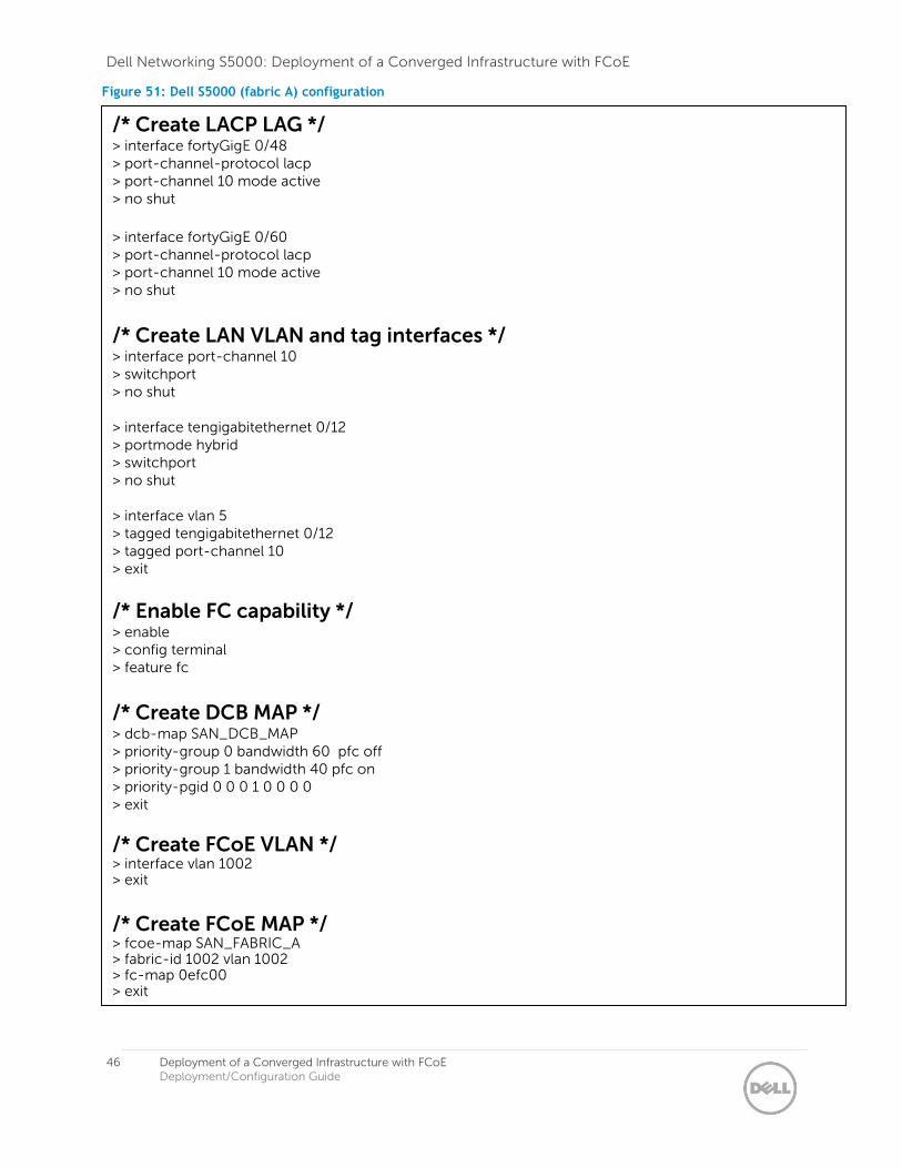
Once the Broadcom BCM57810 drivers and Broadcom Advanced Control Suite 4 are installed, double click the Broadcom Advanced Control Suite 4 shortcut in Windows. Broadcom Advanced Control Suite 4 may already be installed by default. Once opened, you will see something similar to Figure 68. In our case we are using the ‘Adapter4’ CNA. Observe how there are eight functions (or partitions) available (four functions per port). Each function can be seen as a virtual port capable of carrying both LAN and SAN traffic.
Dell Networking S5000: Deployment of a Converged Infrastructure with FCoE
60 Deployment of a Converged Infrastructure with FCoE Deployment/Configuration Guide
Figure 68: View of Broadcom BCM57810S in Broadcom Advanced Control Suite 4
In ‘Control Panel->Network and Internet->Network Connections’, we see eight virtual ports as shown in Figure 69.
Figure 69: Virtual adapter network connections as seen in Windows
By default each function is configured only as a NIC. You can see in Figure 102, for the virtual port highlighted, FCoE is disabled.

Dell Networking S5000: Deployment of a Converged Infrastructure with FCoE
61 Deployment of a Converged Infrastructure with FCoE Deployment/Configuration Guide
To keep things simple and as based on requirements, we use one virtual port on each physical port and disable the rest. This can be done easily through Broadcom Advanced Control Suite 4 by selecting the virtual port in the left-pane, expanding the ‘Resource Reservations’ item on the right-pane, clicking the ‘Configure’ button, clicking the checkbox next to ‘Ethernet/Ndis’ to disable it, and confirming the request. The system will need to be restarted for the changes to take effect. Before restarting the system, we also enable FCoE on the two virtual ports we left the NIC enabled on, #154 and #155. We follow the same method, except instead of removing the checkbox next to ‘Ethernet/Ndis’, we make sure to check the ‘FCoE’ checkbox field. Once the system is restarted, we now see the below.
Figure 70: View in Broadcom Advanced Control Suite 4 of Broadcom BCM57810S with FCoE enabled
Now, in ‘Control Panel->Network and Internet->Network Connections’, we see only two virtual ports as shown in Figure 71.
Figure 71: Virtual adapter network connections as seen in Windows
In Windows Device Manager, we see the below. As you can see the two storage HBAs are now visible as we have enabled two virtual ports with FCoE.

Dell Networking S5000: Deployment of a Converged Infrastructure with FCoE
62 Deployment of a Converged Infrastructure with FCoE Deployment/Configuration Guide
Figure 72: Windows view in Device Manager of one Broadcom BCM57810S CNA with NPAR and FCoE enabled
Creating a NIC Team Since the NICs and HBAs are seen as separate ports, we can treat them as separate entities and create a NIC team with the virtual CNA NICs. To configure a NIC team on our two virtual NIC ports, click the ‘Filter’ drop-down box on the top left of the ‘Broadcom Advanced Control Suite 4’ GUI and select ‘TEAM VIEW’. Right click ‘Teams’ and select ‘Create Team’. Click ‘Next’. Name your NIC Team if desired and click ‘Next’; in our case, we leave it as the default of “Team 1”. Now you should see the options as displayed in Figure 73 below.
Figure 73: NIC teaming virtual NIC ports with Smart Load Balancing and Failover (SLB)
In Figure 73 above, you can see we NIC team using ‘Smart Load Balancing™ and Failover (SLB)”. This allows us to have active-active links up to the S5000 switches. Note, the switch will not be aware of the NIC team and no LAG configuration will be required on upstream switches.
On the next dialog, we select the respective adapters to NIC team.

Dell Networking S5000: Deployment of a Converged Infrastructure with FCoE
63 Deployment of a Converged Infrastructure with FCoE Deployment/Configuration Guide
Figure 74: Selecting virtual NIC ports on Broadcom BCM57810S to NIC team
Next, we leave the default selected so both ports remain in active mode.
Figure 75: Additional configuration to create active/active NIC team on Broadcom BCM57810S
We also leave the Broadcom LiveLink option at the default setting.

Dell Networking S5000: Deployment of a Converged Infrastructure with FCoE
64 Deployment of a Converged Infrastructure with FCoE Deployment/Configuration Guide
Figure 76: We leave ‘LiveLink’ feature on Broadcom BCM57810S at the default setting
| Next, we enter VLAN information. We have setup LAN traffic on VLAN 5 in our topology.
Figure 77: VLAN configuration on Broadcom BCM57810S

Dell Networking S5000: Deployment of a Converged Infrastructure with FCoE
65 Deployment of a Converged Infrastructure with FCoE Deployment/Configuration Guide
Figure 78: Select ‘Tagged’ for the VLAN configuration on Broadcom BCM57810S
Figure 79: We use VLAN 5 for our LAN traffic

Dell Networking S5000: Deployment of a Converged Infrastructure with FCoE
66 Deployment of a Converged Infrastructure with FCoE Deployment/Configuration Guide
Figure 80: We are not configuring additional VLANs
The final step is to confirm the changes.
Figure 81: Commit changes to create NIC team on Broadcom BCM57810S
Once the configuration is complete, we see the below NIC team setup with both virtual ports as members.
Dell Networking S5000: Deployment of a Converged Infrastructure with FCoE
67 Deployment of a Converged Infrastructure with FCoE Deployment/Configuration Guide
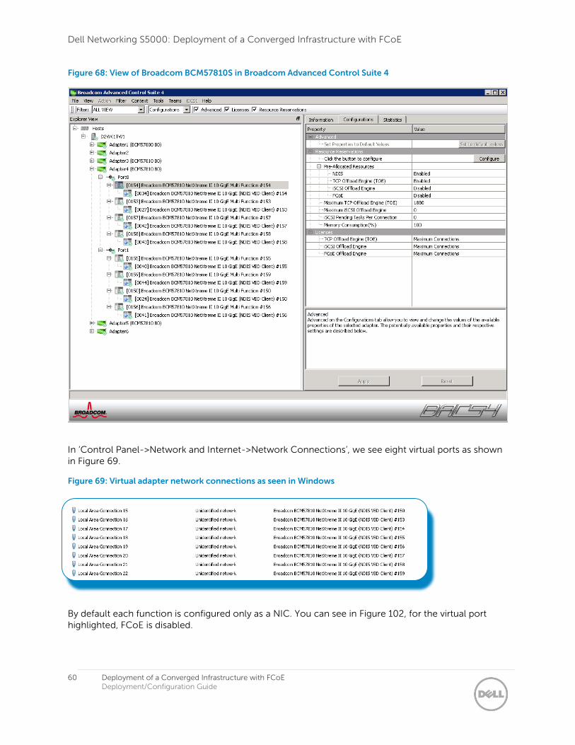
Figure 82: NIC team view in Broadcom Advanced Control Suite 4 of Broadcom BCM57810S
Now Windows Server 2008 R2 Enterprise sees a virtual adapter as shown in Figure 83 and Figure 84.
Figure 83: Windows Server 2008 R2 Enterprise ‘Network adapter’ view of NIC team
Figure 84: NIC team virtual adapter as seen in ‘Device Manager’ in Windows

Dell Networking S5000: Deployment of a Converged Infrastructure with FCoE
68 Deployment of a Converged Infrastructure with FCoE Deployment/Configuration Guide
Dell QLogic QLE8262
QLogic offers CNAs in three formats for Dell 12G servers: QLE8262 standard PCI Express, QME8262-kmezzanine for Dell blade servers, and QMD8262-k for the Dell Network Daughter Card. The Dell QLogic QLE8262 allows for Switch Independent NIC partitioning with up to four partitions per physical port and eight partitions total per 2-port adapter. A partition can be looked upon as a virtual port. This example will use a Dell PowerEdge R720 server with a Dell QLogic QLE8262 CNA and Microsoft Windows Server 2008 R2 Enterprise installed. By default, only the NIC functionality is enabled. FCoE must be manually enabled on the CNA for the virtual HBA ports to be identified in Windows. The configuration of the CNA for FCoE is shown in Figure 85 and Figure 86.
Once the Dell QLogic QLE8262 drivers and QConvergeConsole CLI are installed, double click the QConvergeConsole CLI shortcut in Windows and configure the CNA as shown below. You can see that ‘function 6’ on ‘port 1’ and ‘function 7’ on ‘port 2’ have been configured to handle FCoE.
Figure 85: Dell QLogic QLE8262 CNA on Windows Server 2008 R2 Enterprise

Dell Networking S5000: Deployment of a Converged Infrastructure with FCoE
69 Deployment of a Converged Infrastructure with FCoE Deployment/Configuration Guide
Figure 86: Dell QLogic QLE8262 CNA FCoE/NPAR Configuration

Dell Networking S5000: Deployment of a Converged Infrastructure with FCoE
70 Deployment of a Converged Infrastructure with FCoE Deployment/Configuration Guide
Creating a NIC Team Since the NICs and HBAs are seen as virtual ports, we can treat them as separate entities and create a NIC team with the virtual CNA NIC ports. In Figure 87 and Figure 88, you can see we NIC team the two virtual NIC ports and use ‘Switch Independent Load Balancing’.
In this example, we use Windows Server 2008 R2 Enterprise as an example. To create a NIC team on the virtual NIC ports navigate to ‘Control PanelNetwork and InternetNetwork Connections’ and right click one of the ports you wish to put in a NIC team. Click ‘Properties’. Click the ‘Configure’ button. Next, click the ‘Team Management’ tab as shown in Figure 88.
Now right click on the ‘Teams’ folder and click ‘Create Team’. Choose the type of NIC teaming you desire. In this example we will demonstrate with ‘Switch Independent Load Balancing’. Next, select the ports to add to the NIC team. The rest of the settings we leave as default. Figure 88 displays the virtual port NIC team with two virtual NIC ports as members.
Figure 87: NIC teaming virtual NIC ports with Switch Independent Load Balancing

Dell Networking S5000: Deployment of a Converged Infrastructure with FCoE
71 Deployment of a Converged Infrastructure with FCoE Deployment/Configuration Guide
Figure 88: Dell QLogic QLE8262 adapter propertise displaying the created NIC team
The NIC team will now show in Windows as a new virtual adapter as shown in Figure 89 and Figure 90.
Figure 89: Virtual adapter network connection as seen in Windows
Figure 90: NIC team virtual adapter as seen in ‘Device Manager’ in Windows
As far as the network configuration for the LAN, since ‘Switch Independent Load Balancing’ is being utilized, there is no special configuration that needs to be done on the S5000 switches. We can simply have one link going to each S5000 switch. In our examples in sections A and B, we had tagged the LAN traffic on VLAN 5. We can easily tag the NIC team with VLAN 5 by right clicking the VLAN name and entering the respective VLAN as shown below.

Dell Networking S5000: Deployment of a Converged Infrastructure with FCoE
72 Deployment of a Converged Infrastructure with FCoE Deployment/Configuration Guide
Figure 91: Tagging the NIC team with VLAN 5