Embed Size (px)
Citation preview
Leveraging Existing Market Knowledge to Ensure a
Successful Transition to Pb-Free Medical Products
Randy Schueller, Ph.D. & Cheryl Tulkoff
DfR Solutions
Outline
Intro
Medical Electronics Testing
Reliability Testing to Identify Common Pb-free issues.
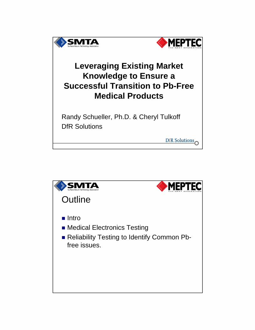
Medical Electronics – Very diverse!
What are ‘medical’ electronics? Is it a realistic category?Some implanted in the body; some outside
Some portable; some fixed
Some complex; some simple
Some control; some monitor; some medicate
All connected by the perception that one’s life may be dependent upon this productCreates a powerful emotional
attachment/effect
Assuring reliability becomes critical
Pb-Free Medical Electronics
A main question is “What can we learn from other Pb-free electronics that will help us most effectively test medical electronic devices as we transition to Pb-free?
Types of Testing
First we should understand that there are different types of testingFeasibility (or Functional) Testing
V&V: Validation & Verification
Production Testing
Reliability Testing
Safety / Regulatory Testing

Feasibility or Functional Testing
Feasibility TestingFunctional testing – confirm that design meets
basic performance requirements
Is it possible?
Proof of concept
Does it work
Failures undesirable
V & V Testing
V&V: Validation & Verification Conformance to specifications & standards
Industry standards like IPC, JEDEC, ISO, FDA, IEC
Environmental Testing
Failures Undesirable
Production Testing
Production TestingStatistical
Optimize design & manufacturing
Failures undesirable
Reliability Testing (our focus)
Two primary objectives:
1. Prove the product can withstand the environment it is going into.ATC, S&V, THB, Heat age, etc.
2. Reveal any weaknesses (in design or process) so risks can be accessed and improvements made. HALT, ESS, Analytical techniques
Some failures are expected.
Safety Testing
Safety / RegulatoryMay overlap with some others
Some fails may be desirable
Varies based on industry
Key Elements of a Product Reliability Plan Reliability Requirement & Targets
Reliability Organization Structure
Reliability Activities (Reports, Tests, Analyses)
Schedule
Supply chain management /oversight
Listing of relevant standards, specifications, procedures

General Reliability Management Needs Create & work to reliability plan
Define and Identify external servicesTest
Failure Analysis
Reliability Training
How to ID the Best Reliability Tests Key Points:
Must test at increased stresses, not actual expected stresses, to create failures then use this information to improve reliability Only true upper stress limits for reliability testing are test
equipment capability & technology limits (solder melt points, Tg of polymers, etc.)
Should not drive failure mechanisms not possible in the field.
Should target certain failure mechanisms (but unexpected failure mechanisms should be investigated).
Have ability to generate a failure distribution function.
How to Create Reliability Tests
General Reliability Testing Approach Perform FMECA (Failure Modes, Effects & Criticality
Analysis) / QFD (quality functional deployment) to determine likely service fails
Identify stressors
Plan to simulate stressors in test
Determine methods to identify failures (x-ray, x-section, dye-n-pry, etc.)
What are the Pb-Free Failure Mechanisms that should be Stressed? Pb-free issues can be sorted by the
product design, material selection and expected user environment.
The following information may be included in a product FMEA.
Medical Product with BGAs A product with BGAs (incl CSPs & FC)
should be concerned with:Head-in-pillow defects
Pad cratering
Achieving optimum reflow temperature
Testing & AnalysisBall pull or board bend testing
Evaluate assembly process using x-sectioning, optical microscopy along edges, etc.
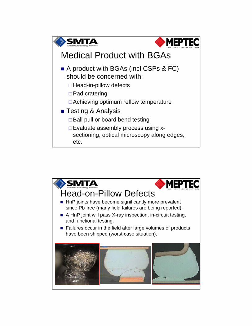
Head-on-Pillow Defects HnP joints have become significantly more prevalent
since Pb-free (many field failures are being reported).
A HnP joint will pass X-ray inspection, in-circuit testing, and functional testing.
Failures occur in the field after large volumes of products have been shipped (worst case situation).

What is the Root Cause mechanism?
HnP occurs when the flux on the exterior of the paste dries out prior to reaching liquidus temperature.
In the case of warping, the paste and ball are not in contact at liquidus and come back together upon cooling.
Result is oxidized surfaces that prevent intermixing.
The higher temperatures required for lead-free assembly exacerbates both causes.
What variables impact HnP?
Supplier Issues: Flux activity, slump resistance, tackiness.
Sphere oxidation
IC package warpage
Process Issues Poor paste printing (insufficient volume).
Component placement (insufficient pressure, off pad).
Reflow Too much time in preheat.
Insufficient time above liquidus (TAL).
Oxygen content in reflow too high

Detection
X-ray can detect gross examples
Cross sectioning is most effective.
Pad Cratering SAC solder is less compliant than SnPb so
tensile stress is transferred to the laminate.
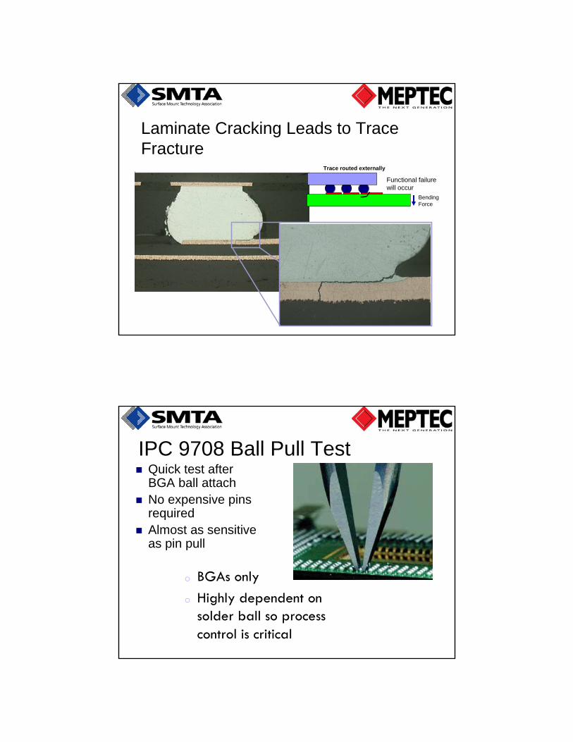
Laminate Cracking Leads to Trace Fracture
BendingForce
Functional failurewill occur
Trace routed externally
IPC 9708 Ball Pull Test Quick test after
BGA ball attach No expensive pins
required Almost as sensitive
as pin pull
o BGAs only
o Highly dependent on solder ball so process control is critical

IPC 9702-Bend Test
Used to characterize fracture strength of board level interconnects
Failure modes from this test are not easily differentiated High speed test
Short duration
Failures in quick succession
HALT Testing is also effective in reproducing pad crater defects.
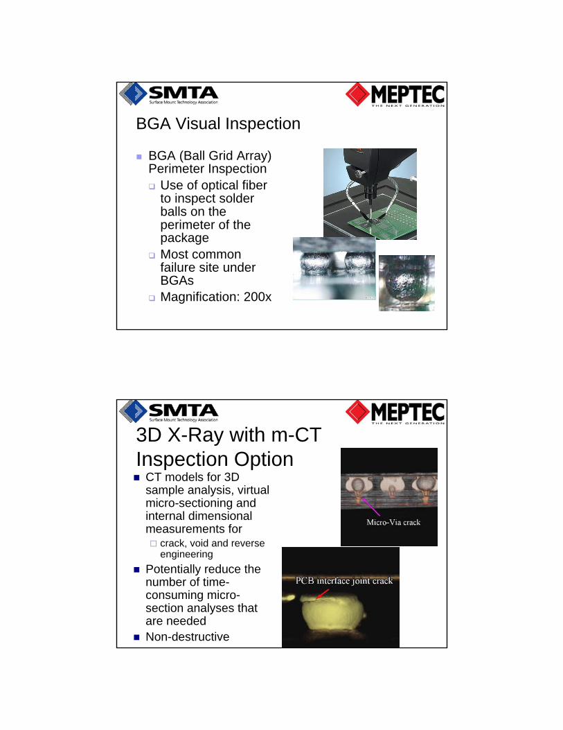
BGA Visual Inspection
BGA (Ball Grid Array) Perimeter Inspection Use of optical fiber
to inspect solder balls on the perimeter of the package
Most common failure site under BGAs
Magnification: 200x
3D X-Ray with m-CT Inspection Option CT models for 3D
sample analysis, virtual micro-sectioning and internal dimensional measurements for crack, void and reverse
engineering
Potentially reduce the number of time-consuming micro-section analyses that are needed
Non-destructive

Hand Held Medical Products
Expected failure mechanisms include:Shock damage to BGAs or other high stress
solder joints (pad cratering or SJ failure -especially with ENIG surface finish).
Thermal cycle failure also a possibility.
Tests and AnalysisStressors are shock testing or board bend
testing.
Analyze failures with x-section and dye-n-pry.
Brittle failure with SAC on ENIG SAC solder with ENIG surface finish can result
in brittle failure at the intermetallic layer.
“Board Level Drop Test Reliability of IC Packages”, Chai TC, et.al., Institute of Microelectronics
JEDEC (JESD22-B111) standard testing 1500 G’s, 0.5 mS pulse width
Thermal Cycling
Hand held products will experience indoor/outdoor temperature swings.
The number of cycles should be projected (near worst case) and an ATC plan developed.
Analyze for solder joint cracking with x-section and dye-n-pry.
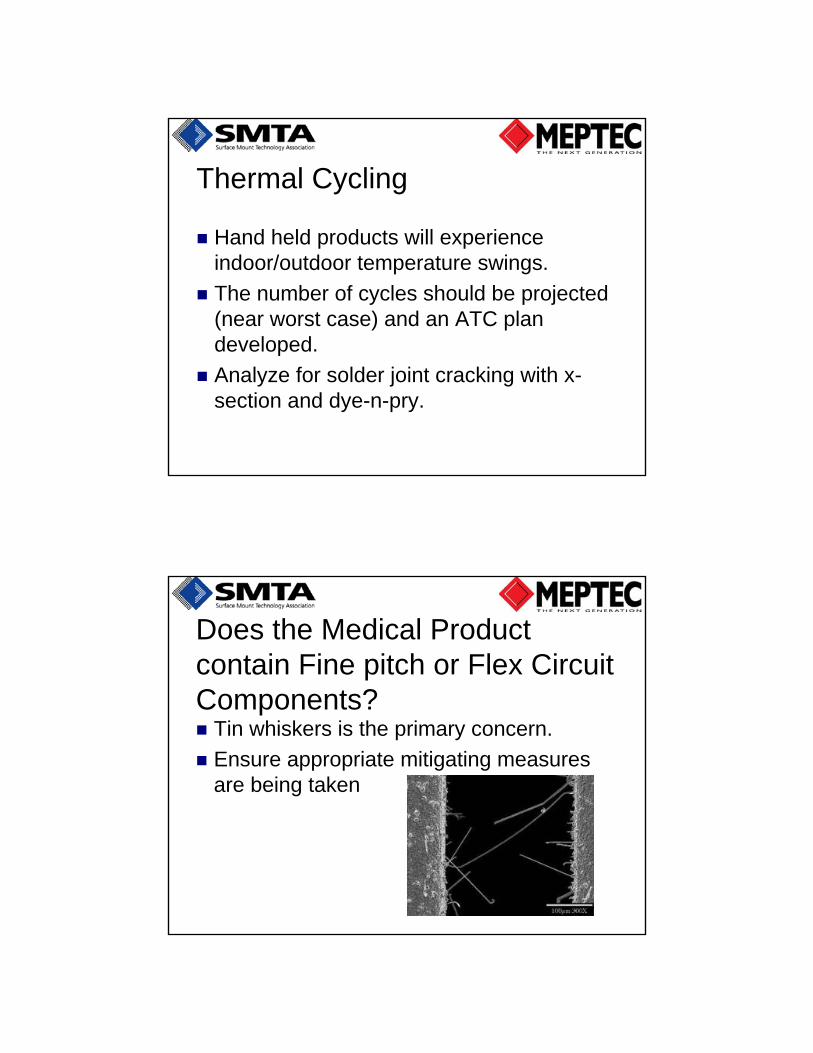
Does the Medical Product contain Fine pitch or Flex Circuit Components? Tin whiskers is the primary concern.
Ensure appropriate mitigating measures are being taken

D-Sub Connectors with bright tin shells have been known to grow whiskers that can short our pins (if connector is unmated).
Avoid Bright Tin (shells & shields)
Whiskers also found to grow in screw holes.
Ref: L. Flasche & T. Munsun, Foresite, Inc. 9/09.
Ref: Emerson
Contact Pressure on Flex Cables Flex Circuits with Connector Mating
Pressure from contacts with the soft polymer substrate produces whiskers. Don’t use Sn plating in mated flex with a spacing less than
200 micrometers.
Use gold plating with such conditions.
High humidity environments
Risk is metal migration due to flux residue or cleanliness issues (flux can bake onto the board and is more difficult to clean off).
Test with THB (example 130C/85%RH/Bias)
Measure ionic cleanliness
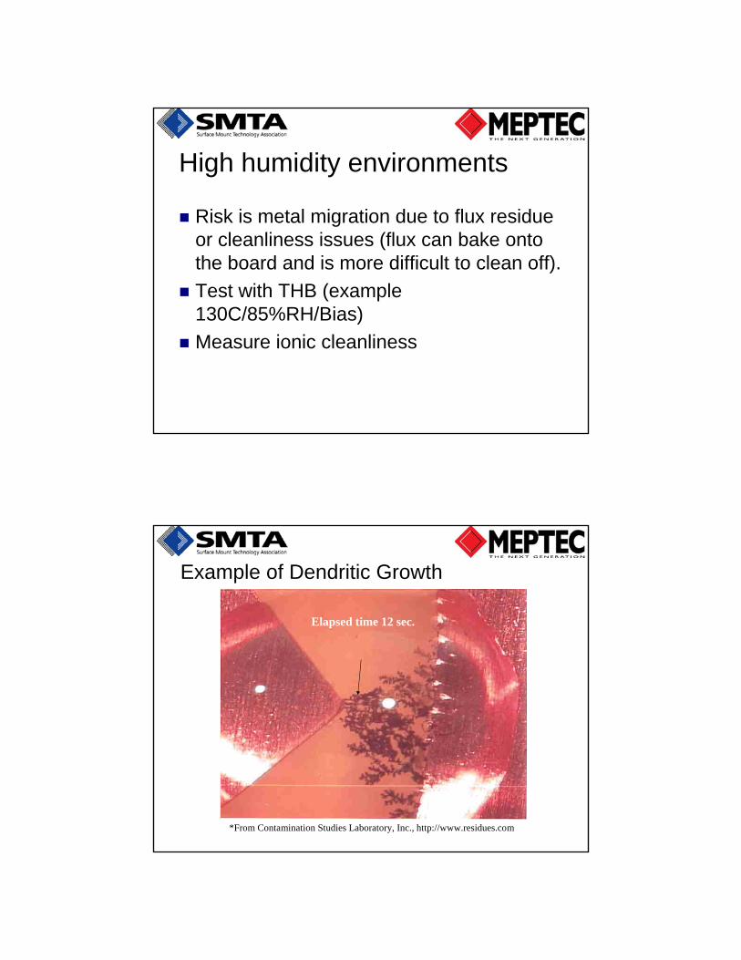
*From Contamination Studies Laboratory, Inc., http://www.residues.com
Elapsed time 12 sec.
Example of Dendritic Growth
Flux Residues
Residues of no-clean soldering? Water-soluble dicarboxylic acids
Hygroscopic polyethylene glycol ethers
List of potential weak organic acids (WOAs) Benzoic, Butyric, Formic, Lactic, Malonic, Oxalic,
Propionic, Succinic, Citric, Glutaric, Adipic, Malic
Optimum flux Acids are neutralized after soldering process
Residual wetting agents are minimized
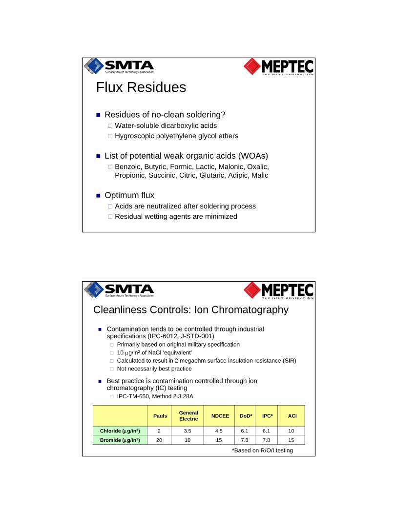
Cleanliness Controls: Ion Chromatography
Contamination tends to be controlled through industrial specifications (IPC-6012, J-STD-001) Primarily based on original military specification
10 g/in2 of NaCl ‘equivalent’ Calculated to result in 2 megaohm surface insulation resistance (SIR) Not necessarily best practice
Best practice is contamination controlled through ion chromatography (IC) testing IPC-TM-650, Method 2.3.28A
*Based on R/O/I testing
PaulsGeneral Electric
NDCEE DoD* IPC* ACI
Chloride (g/in2) 2 3.5 4.5 6.1 6.1 10
Bromide (g/in2) 20 10 15 7.8 7.8 15

Sources of Contaminants (cont.)Ion Possible Sources
Cl Board Fab, Solder Flux, Rinse Water, Handling
Br Printed Board (flame retardants), HASL Flux
Fl Teflon, Kapton
PO4 Cleaners, Red Phosphorus
SO4 Rinse Water, Air Pollution, Papers/ Plastics
NO4 Rinse Water
Weak Organic Acids Solder Flux
High Temperature Products
Medical equipment that runs hot will require forced air cooling.
If Immersion silver surface finish is used then creep corrosion should be evaluated with corrosion testing.
Plated through-hole vias can fracture so should be tested (IST, Thermal cycle, etc.)
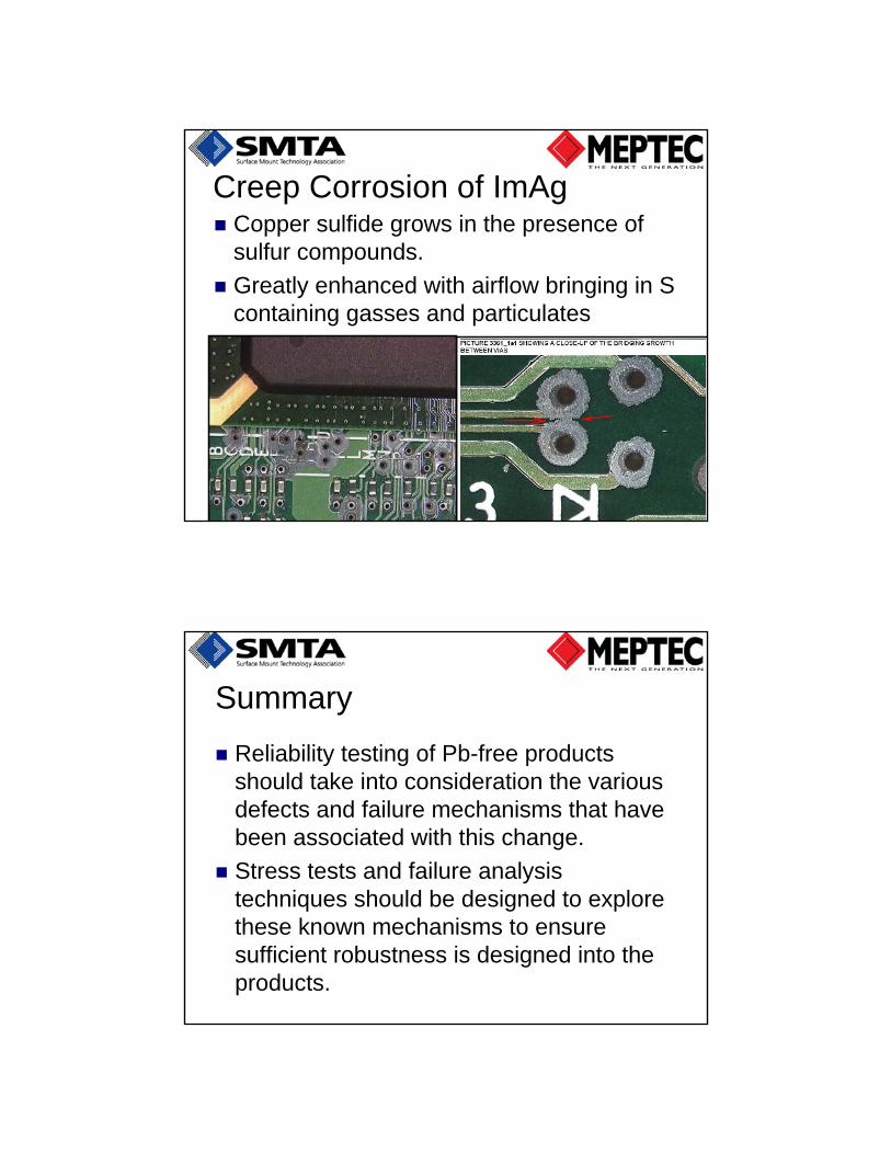
Creep Corrosion of ImAg Copper sulfide grows in the presence of
sulfur compounds.
Greatly enhanced with airflow bringing in S containing gasses and particulates
Summary
Reliability testing of Pb-free products should take into consideration the various defects and failure mechanisms that have been associated with this change.
Stress tests and failure analysis techniques should be designed to explore these known mechanisms to ensure sufficient robustness is designed into the products.