Embed Size (px)
Citation preview
1 EN2R-9055 0210R1-NE
S4564 A-T, BF, DF, QF, TF, AT-TTIGNITION CONTROL FOR COMPACT COMBINED IGNITION SYSTEM
APPLICATIONThe Compact Combined Ignition (CCI) system has been developed for application in gas fired domestic central heating boilers, combi boilers and warm air furnaces or water heater appliances with an automatic ignition system.For these systems, the S4564 A..T,BF, DF, QF, TF, AT..TT ignition controls are used in conjunction with the VR46.. series gas controls to provide an optimised safety sub-system for programmed safe light up and flame supervision of the main burner of the appliance.The combined system of ignition control and gas valve thus provides programmed safe light up, flame supervision and control of gas flow to the main burner and/or pilot burner of the appliance.For glossary of terms, abbreviations and symbols, see document EN2R-9039.For details of the Compact gas controls please refer to Product Handbook EN2R-9000. For an up to date copy please contact your nearest Honeywell office.
EN2R-9055 0210R1-NE2
CONTENTS
Description 3Valves .................................................................................3Ignition control ....................................................................3
Features 4General...............................................................................4Ignition control ....................................................................4Electrical connections.........................................................4
Dimensional drawing 5
Functional specification 6Model..................................................................................6Timing.................................................................................6Ignition ................................................................................6Flame sensing ....................................................................6Lock-out and reset..............................................................6Indications (optional) ..........................................................6Safety .................................................................................6Operation at under voltage.................................................7Reliability and product life...................................................7
Control specification for S4564 AT-TTModel..................................................................................8TTB trip level ......................................................................8TTB/Aquastat shutdown time .............................................8NTC sensor rating ..............................................................8
Electrical specificationsPower consumption ............................................................9Electrical rating ...................................................................9Electrical connections.........................................................9Length of flame sensing cable............................................9Length of ignition cable(s) ..................................................9Length of NTC sensor cable...............................................9Length of other wiring for external components .................9Fusing.................................................................................9
Housing specificationDegree of protection .........................................................10Material.............................................................................10Mounting...........................................................................10Printing .............................................................................10
Environmental specificationHumidity............................................................................11Ambient temperature ........................................................11Storage .............................................................................11Internal..............................................................................11
Wiring diagrams 12
System operation 14General ............................................................................ 14S4564 suffix AT and PT (see Figure 11.) ......................... 14S4564 suffix A and P ....................................................... 14S4564Suffix BT and QT (IP application see Figure 12) ... 14S4564 suffix BF and QF (IP application).......................... 14S4564 suffix B and Q (DBI with flame relay).................... 14S4564 suffix CT and RT (see Figure 13.) ........................ 14S4564 suffix C and R ....................................................... 14S4564 suffix DT and TT (IP application see Figure 14) ... 14S4564 suffix DF and TF (IP application) .......................... 15S4564 suffix DT or D and TT or T (DBI application) ........ 15Lock-out and reset ........................................................... 15LPG valve and gas pressure switch................................. 15High limit operation .......................................................... 15TTB/Aquastat Operation .................................................. 15
Installation, adjustments and final checkoutInstallation........................................................................ 18Wiring............................................................................... 18Spark gap......................................................................... 18High voltage ..................................................................... 18EMC guidelines................................................................ 18Supply voltage polarity..................................................... 18Checking flame current .................................................... 18Final checkout of the installation...................................... 18Maintenance and service ................................................. 19
VariousQuality assurance statement ............................................ 20Standards and approvals.................................................. 21Ordering information......................................................... 22
3 EN2R-9055 0210R1-NE
DESCRIPTION Valves
The Compact Combined Ignition (CCI) system controls and performs all the functions required for safe ignition, flame supervision and for safe regulation of the gas flow to the pilot and/or main burner.The CCI consists of a gas valve of the VR46.. series and a dedicated ignition control of the series S4564 which is connected directly to it.
Ignition control
The S4564 series ignition controls can be directly electrically connected to a VR4605 .. series gas control for DBI or a VR4601 .. series gas control for IP ignition.The S4564 A..T ignition controls provide automatic spark ignition for direct gas burner applications and for intermittent pilot gas burner applications with safety timer.The S4564 AT .. TT ignition controls provide automatic spark ignition for direct gas burner applications and for intermittent pilot gas burner applications with safety timer.An external NTC sensor can be placed as water temperature sensor in order to add an aquastat function with fixed anti-cycling time.An external NTC sensor placed as downdraft detector can be connected to the ignition control. In case of (partially) blocked exhaust, the sensor will reach its temperature switching point and the ignition control will shut down the gas flow during a predetermined period.This feature can be used as combustion products discharge safety device (TTB) for use in type BIIBS appliances and is designed according to EN 297 and DVGW-VP100 standards..
EN2R-9055 0210R1-NE4
FEATURES General
• All burner control functions concentrated in one reliable and optimised system.
• Specially designed to provide the optimum system solution in gas appliances with a DBI or IP system to light the main burner.
• Both gas control and ignition control incorporate time proven design concepts assuring reliability.
·• Easy assembly of ignition control on the gas control by plugging it on from the top.
·• Mounting orientation may be within + or - 90° from the electric on/off valve operator upright position.
Ignition control
• · Accurate safety timer.
·• Hybrid technology for high reliability.
• Flame supervision.
• Flame rod with protective impedance.
• Built-in ignition or relay to switch a external igniter
• Optional 4 mm round pin for high voltage ignition output.
• Extended spark ignition and stabilisation time.
• Optional flame relay or flame opto output.
• Optional output for an external valve or hour counter.
• Full operating sequence after flame loss.
• Volatile or non volatile lock-out according to EN 298.
• Optional internal alarm neon indication.
• Optional internal reset button and/or alarm neon.
• External reset and alarm.
• Optional permanent alarm indication.
• Optional call for heat LED indication.
• Optional flame LED indication.
• Optional phase-neutral independent operation, flame sensing independent of safety ground potential.
• Optional LPG valve and GPS connection (atmospheric controls).
• Optional EMC filter.
• Under voltage protection.
• Optional TTB/Aquastat function (using 1 MΩ NTC sensor) (suffix T types).
• Anticycle time for the optional aquastat function
• Accessible NTC sensor contacts.
• Optional flame retarding housing (UL94-V0)
Electrical connections
• Connection of the ignition control to the gas control is made entirely by plugging the ignition control on.
• Electrical connections are positioned on top and are made by Molex3001 connectors or optional RAST5 connectors (not all executions possible with RAST5).
• Ignition and flame detection connections on the CCI housing are at the gas outlet end of the valve.
5 EN2R-9055 0210R1-NE
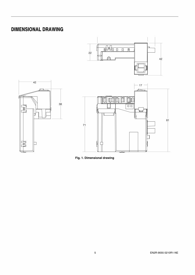
DIMENSIONAL DRAWING
Fig. 1. Dimensional drawing
42
38
71
81
17
42
22
EN2R-9055 0210R1-NE6
SPECIFICATIONS Model(see also system operation)Suffix A: atmospheric, direct burner ignitionSuffix B: atmospheric, direct burner ignition with flame relay output Suffix BF:atmospheric intermittent pilot burner ignition including safety timerSuffix C: fan assisted, direct burner ignitionSuffix D: fan assisted, direct burner ignition with flame relay output Suffix DF:atmospheric intermittent pilot burner ignition including safety timerSuffix P: as A but with volatile lock-outSuffix Q: as B but with volatile lock-outSuffix QF:as BF but with volatile lock-outSuffix R: as C but with volatile lock-outSuffix T: as D but with volatile lock-outSuffix TF:as DF but with volatile lock-outSecond suffix letter T:With TTB/Aquastat control
TimingSelf check time (Tc): 0 .. 1,5 s ± 25 %(refer to O.S.number).Waiting time (Tw): 0 .. 30 s - 0% + 120%.(refer to O.S.number).Prepurge time (Tp) (C, D, R, T): 0 .. 30 s - 0% + 120%.(refer to O.S.number).Safety time (Ts): 2 .. 250 s + 0% - 25% (-20 % for Ts > 10 s)(refer to O.S.number).Extended spark ignition time (Text) (A, C, P, R): 0 ..Ts ± 25 %(refer to O.S.number) (also depending on elaps of safety time: Text is maximal at the start of Ts and zero at the end of Ts).Stabilisation time (Tstab) (BF, DF, QF, TF): 0 ..Ts ± 25 %(depending on elaps of safety time Tstab is maximal at the start of Ts and zero at the end of Ts).Recovery time after lock-out (period in which reset is not possible): > 15 s (nominal value is 4 s).Recovery time after reset (extended waiting time): dependent on Ts and Text or Tstab, nominal 55 s (for Ts = 55 s. and Tstab = 6 s.)Recovery time after switching mains off for S4564 AT..TT.: > 10 s (period in which ignition control continues with TTB aquastat cycles , nominal value is 3 s)
IgnitionSpark voltage: > 15 kV at 40 pF load(optional > 20 kV for gas-air applications, refer to O.S.number)Repetition rate: 1 .. 40 Hz ± 30% (refer to O.S.number)Spark pulse energy: 5 µAs ± 40% (optional 15 µAs, refer to O.S.number)Ignition can be:Closed loop: Two tabs available for the floating ignition voltage.To ground: One side of the spark transformer is internally wired to the ground connection.Combined with flame sensing: One side of the transformer is internally wired to a spark gap or VDR and wired to the flame sensing circuit. (note that the maximum spark voltage decreases with the spark gap or VDR voltage).Maximum spark gap: 3.5 mm.
Flame sensingFlame detection threshold:for optional phase independent systems: 0.5 µAfor phase dependent systems: 0.9 µAFlame off threshold:for optional phase independent systems: 0.25 µAfor phase dependent systems: 0.5 µAResponse time flame present : > 0.2 sResponse time flame off: (TFR) at Iflame = 2 µA < 1 s(other values upon request)Short circuit current (in situations with TFR < 1 s) < 100 µA ac.Flame relay / Flame opto / Main valve relay: switches when a flame is detected and Text or Tstab has elapsed.
Lock-out and resetOptional internal alarm indication and reset.Internal or external reset switch not standard available for P, Q, R, T.An add-on part (bracket) is available with a suitable reset switch / alarm neon with a RAST5 connector connected to the CCI.
Indications (optional)Call for heat: LED (red), on when the call for heat is present.Lock-out: neon (orange), on when the ignition control is in lock-out.Flame: LED (green), on when a flame is detected.
SafetyThe S4564 ignition controls fullfill the demands of the EN60730 and EN298.All connections are coupled to mains voltage, except those that are specified different.The PCB layout is made with clearance and creepage distances as specified for a clean environment according to EN 60730, 3rd edition.Flame relay used for main valve control is fail safe. Simultaneously opening of pilot valve and main valve is not possible (single fault condition according to EN298).The flame rod has protective impedance in accordance with EN60730.Optionally it can have protective impedance with the use of two resistors in accordance with IEC65, par. 14.The sensor connection has protective impedance in accordance with EN60730. The separate resistors of the protective impedance do not fullfill the demand of IEC65.For the S4564 a Failure Mode and Effect Analysis with fault modes in accordance with to EN298 is performed and judged as correct.
7 EN2R-9055 0210R1-NE
Operation at under voltageThe S4564 ignition controls are intrinsicly safe under all mains voltage from zero to maximum specified.The ignition control functions according to spec within the given mains supply voltage range and tolerance on this range.Undervoltage disabling limit: 173 Vac ± 10 Vac.At voltages below the under voltage disabling limit, the ignition control is disabled and will not start the program sequence.At voltages between the undervoltage disabling limit and the lowest value of the mains supply voltage range, the ignition control works functionally correct exept spark frequency for O.S. numbers with high spark energy (15 µAs) (specific ignition control may not spark). Parameters are not guaranteed inside spec but safety time is not elongated, waiting time is not shortened and lock-out function is guaranteed down to 162 Vac mains voltage.At the mains voltage level where the undervoltage disabling does not work anymore, the voltage level is too low to open the gasvalve (nominal about 150 Vac).
Reliability and product lifeThe S4564 ignition control will withstand:500.000 cycles for safety and main valve operator of the gas valve.250.000 cycles at maximum loads.6.000 lock-out operations with maximum loads.1.000 hours sparking (type tested in life test while continuously sparking).
EN2R-9055 0210R1-NE8
CONTROL SPECIFICATION FOR S4564 AT-TTModelThe specific O.S. number defines the trip level and the TTB/Aquastat shutdown time. See also TTB/Aquastat operation.
TTB trip levelNominal trip level is at sensor resistance equal to 295 kW with an accuracy of 5% (equal to 50 °C for a 1 MΩ NTC).The trip level can have a factory setting lower than 295 kΩ (higher temperature) by placing a series resistor inside the ignition control (refer to O.S. number). Also on the connector an extra series resistor can be placed.The BT1009 has a trip level of 185 kΩ ± 15 kΩ (60 °C ± 2 °C for a 1 MΩ sensor)
TTB/Aquastat shutdown timeNominal TTB/Aquastat shutdown time is 15 minutes with an accuracy of 25%.The shutdown time can have a factory setting lower than 15 minutes by placing a series capacitor inside the ignition control (refer to O.S. number).
NTC sensor ratingThe sensor supply voltage applied by the ignition control is < 17 Vdc, safely accesible in accordance with EN 60730. Intended for use with a 1 MΩ NTC sensor from the T7335 B series.

9 EN2R-9055 0210R1-NE
ELECTRICAL SPECIFICATIONPower consumption5 VA (without gas valve(s))
Electrical ratingMains supply: 230 ... 240 Vac (+10%, -15%), 50/60 HzThe total current drawn is < 2 A, cos ϕ > 0.6 ( < 3 A during maximal 1 min.)Heat demand input: phase of mains supply. In case of permanent alarm indication, a resistor of 22 kΩ is placed internally between heat demand input and permanent live.Permanent live: phase of mains supply.Neutral: neutral of mains supply.Gas valve: Suitable for VR46...High limit control: 230 ... 240 Vac, 50/60 Hz, 1 A max, cos ϕ > 0.6. Placed in series with gas valve neutral.Flame relay output: 230 ... 240 V ac max, 50/60 Hzor 24 V dc, 1 A max, cos ϕ > 0.6 (B, D, Q, T only, not on BT, DT, QT, TT)Volt free contacts of common and normally open available, with safe separation towards mains voltage. Optionally the NTC contact is available (no safe separation)In an IP application the flame relay is wired as main valve control suitable for VR4601.Flame opto output: Use a 10 kΩ resistor connected to 5 V. Note: the opto coupler interface needs a debounce time of 200 ms in order to guarantee correct operation. (B, D, Q, T only, not on BT, DT, QT, TT)Alarm: 230 ... 240 Vac, 50/60 Hz, output 1 mA max.(e.g. neon light with internal series resistor > 150 kΩ).In case an optocoupler with series diode 1N4007 is used (both cathodes towards Alarm/Reset common), series resistance must be > 39 kΩ.Reset: < 45 V, < 500 mA, intended for reset switch.Air Pressure Switch: 230 ... 240 Vac, 50/60 Hz 1 A max, cos ϕ > 0.6.Fan: 230 ... 240 Vac, 50/60 Hz, 1 A max, cos ϕ > 0.6.Not possible together with permanent alarm .Gas Pressure Switch: 230 ... 240 Vac, 50/60 Hz 1 A max, cos ϕ > 0.6.LPG valve: 230 ... 240 Vac, 50/60 Hz, 1 A max, cos ϕ > 0.6.Not possible together with permanent alarm .High voltage ignition: > 15 kV at 40 pF load (optional > 20 kV). Safely accesible according to EN 60730 if sparking frequency is < 25 Hz.Ground: functional earting for EMC filter and spark to ground applications (no protective earthing).Flame sensing: 230 ... 240 Vac, 50/60 Hz, connected with high impedance to mains live. Safely accesible in accordance with EN 60730. Optionally using resistors in the protective impedance according IEC65 par.14 for VDE approval.NTC sensor input: < 17 Vdc connected with high impedance to mains live. Safely accessible in accordance with EN 60730.
Electrical connectionsSee also the chapter 13, installation adjustments and final checkout.NTC sensor input: pin 1 and 2 (pin 1 and 2 of X162 )Flame output: (DBI only)C to pin 1.NO to pin 2.NC to pin 3.Flame output if wired as main valve control in IP:Internally directly wired to the main valve.Flame opto output: pin 1, gnd to pin 2Neutral (A, B, P, Q): pin 4 (pin 3 of X036)
APS NO (C, D, R, T): pin 4 (pin 3 of X036)Heat demand input: pin 5 (pin 2 of X036)Permanent live:.pin 6 (pin 1 of X036)APS C (C, D, R, T): pin 7 (pin 2 of X111)Gas pressure switch: pin 7 and pin 8 (pin 1 and 2 of X111)Neutral (C, D, R, T): pin 8APS NC (C, D, R, T): pin 9 (not on RAST5)Optional Neutral (A, B, P, Q): pin 9 (not on RAST5)LPG valve or fan:N to pin 10 (pin 2 of X034 )L to pin 11 (pin 1 of X034)Second gasvalve live: pin 12 (not on RAST5)internally wired to the second gasvalveSecond gasvalve neutral: pin 9 (in a phase-neutral mains situation and IP application this may also be connected to mains neutral)Second gasvalve neutral: pin 10 (in a phase-phase mains situation and IP application to prevent switch on of the valve by earthfout on the valve, pin 10 internal connect to neutral via gas relay contact,HL switch and J15_2)High limit control: pin 13 and 14 (pin 1 and 2 of X099) Optionally internally bridged (refer to connection diagram on specific O.S.number)Reset and alarm:Alarm: pin 15 (pin 3 of X050 )Common: pin 16 (pin 2 of X050)Reset: pin 17 (pin 1 of X050)Gas valve(s):Internally directly connected to the gas valveHigh voltage ignition: 2.8 x 0.5 mm spade terminal.Optional High voltage ground: internally wired to ground.Optional 2.8 x 0.5 mm spade terminalor 4 mm round terminal.Flame sensing:4.8 x 0.8 mm spade terminal.Optionally left outGround: Internally directly connected to the second valve / main valve (functional ground only). Safety ground (PE) to be connected to the tab on the valve.Optional hour counter: Between Heat demand input (pin 4 or 16) and high limit pin 14.
NOTE 1: Optional hour counter is connected parallel to the gasvalve (ratings see gasvalve)
Length of flame sensing cable 1 m max.
Length of ignition cable(s)0.5 m max.
Length of NTC sensor cable3 m max. NTC sensor and connections to be wired inside the appliance.
Length of other wiring for external components1 m max.
FusingThe ignition control should be externally fused.In order to prevent unsafe conditions at too high current, the ignition control has internal non replaceable fuses, rated at 4 A ± 50%.These fuses will be blown long before the maximum 16 A external fuse switches off.
EN2R-9055 0210R1-NE10
HOUSING SPECIFICATIONDegree of protectionIP00 standardIP20 for ignition controls with separate ignition and flame sensing and spark frequency < 25 Hz.With the correct isolation of connectors and side outlets: IP 40 (accesoiries not provided by Honeywell).The housing provides a clean environment according to EN 60730.
MaterialStandard ABS UL94 HB, optional PP0 UL94 V0.
MountingThe housing is intended to be fixed directly on the compact gas valve VR41...The allowed mounting orientations is identical to the allowed mounting orientation of the compact gas valve, see Product Handbook EN2R-9000.
PrintingThe housing will have printing of O.S. number, brandname (ie Honeywell), supply voltage, safety time, CE number, production location, production weekcode and connection diagram.
11 EN2R-9055 0210R1-NE
ENVIRONMENTAL SPECIFICATIONHumidity90% RH max. at 40 °C, non condensing.10.2 Ambient temperature0 ... 60 °C-15 ... 60 °C (upon request).10.3 Storage-30 ... 70 °C, 95% RH max. at 40 °C
InternalPCB spot temperature is limited to 60 °C DT (120 °C max.). Component temperature is limited to a value as specified (electrolytic capacitors) or limited to a value corresponding with the maximum PCB spot temperature as mentioned above.
EN2R-9055 0210R1-NE12
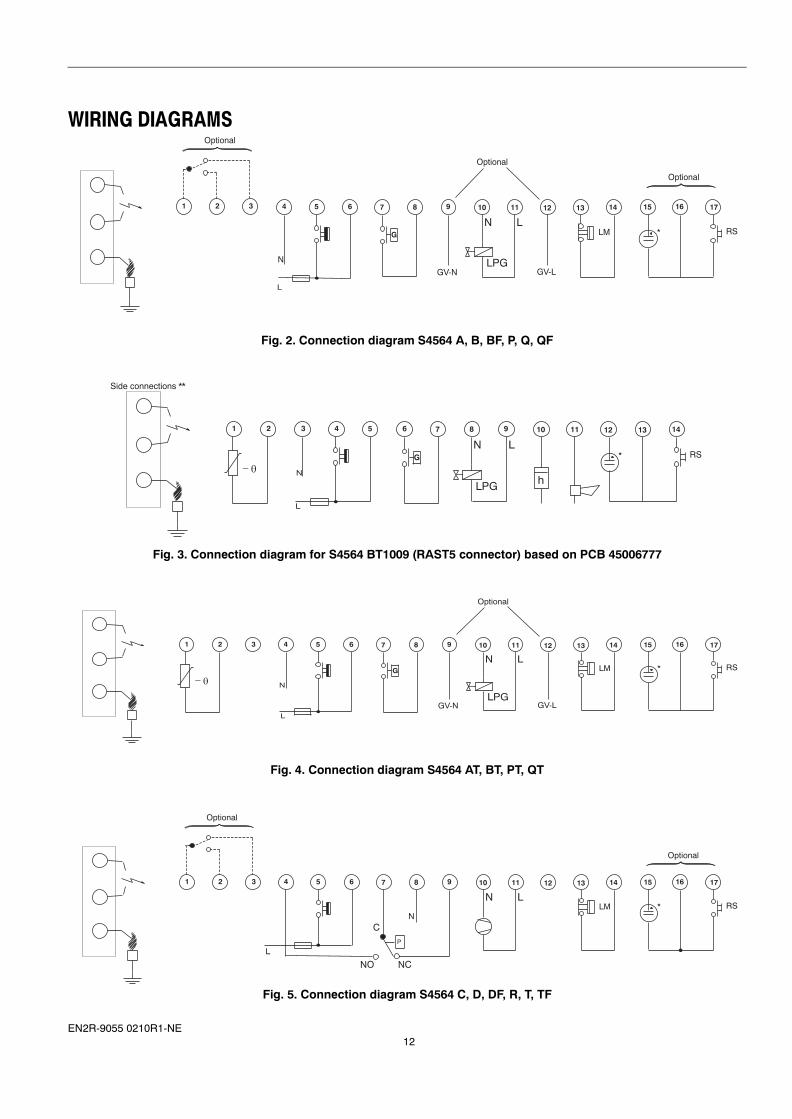
WIRING DIAGRAMS
Fig. 2. Connection diagram S4564 A, B, BF, P, Q, QF
Fig. 3. Connection diagram for S4564 BT1009 (RAST5 connector) based on PCB 45006777
Fig. 4. Connection diagram S4564 AT, BT, PT, QT
Fig. 5. Connection diagram S4564 C, D, DF, R, T, TF
N
LM
Optional
RS
Optional
1110987654 12 13 14 15 16 17
G
GV-N LPG
LN
GV-L
*
L
Optional
321
N
RS
Side connections **
1110987654321 12 14
G
LPG
LN*
− θ
13
h
L
N
LM RS
1110987654321 12 13 14 15 16 17
G
GV-N LPG
LN
GV-L
*
− θ
L
Optional
NLM RS
Optional
1110987654321 12 13 14 15 16 17
LN*
P
L
Optional
C
NCNO
13 EN2R-9055 0210R1-NE
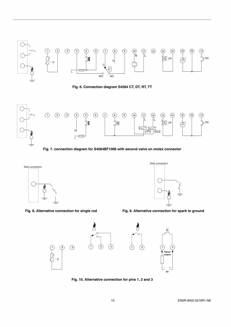
Fig. 6. Connection diagram S4564 CT, DT, RT, TT
Fig. 7. connection diagram for S4564BF1006 with second valve on molex connector
Fig. 8. Alternative connection for single rod
Fig. 9. Alternative connection for spark to ground
Fig. 10. Alternative connection for pins 1, 2 and 3
NLM RS
111098765431 12 13 14 15 16 17
LN*
P
C
2
− θ
L
NCNO
N
LM RS
1110987654321 12 13 14 15 16 17
G
LPG
L*
GV2
L
L
Side connection Side connection
321
− θ
21 21
- +
5V
Flameoutput
321
EN2R-9055 0210R1-NE14
SYSTEM OPERATIONGeneralThe S4564 ignition controls provide sparking to ground.Closed loop sparking or combined sparking and flame sensing on one terminal is possible.S4564 A, C, P, R are designed for direct burner ignition systems.S4564 B, D,Q, T are designed for direct burner ignition systems with flame relay outputS4564 BF, DF,QF, TF are designed forintermittent pilot burner ignition systems.S4564 A, B, P, Q are designed for atmosferic systems and gas-air coupled systems.S4564 C, D, R, T are designed for fan assisted systems with APS check.S4564 A, B, C, D have non volatile lock-out.S4564 P, Q, R, T have volatile lock-out.S4564 with second letter T have TTB/Aquastat control.
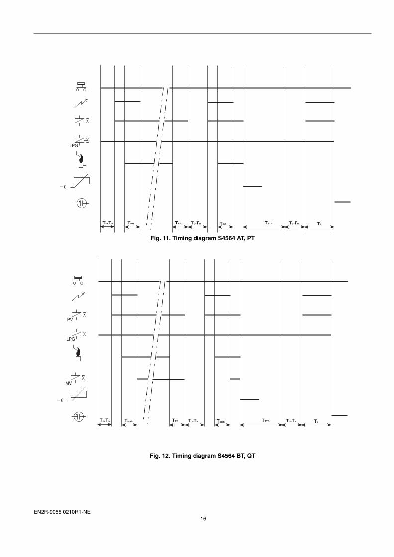
S4564 suffix AT and PT (see Figure 11 .)When there is a call for heat, the LPG valve output is energised. The self check time (Tc) plus waiting time (Tw) elapse before the built-in igniter and gas valve are switched on.The ignition spark ignites gas and resulting flame is detected by the flame rod.If flame is established, ignition is switched off after an extended ignition time (Text).If flame is not established within the safety time (Ts), the ignition control locks out and the alarm indicator is on. The LPG valve is deenergised.If the flame is lost during normal run, the gas valve closes after the flame failure response time (TFR) and the ignition control repeats start sequence. If the flame disappears during a period shorter than TFR, no reaction will follow.If the resistance value of the NTC sensor drops below the threshold, then the gas valve is switched off.After a predetermined time (TTBB), the ignition control restarts if the sensor resistance is above the threshold.A self check time (Tc) plus a waiting time (Tw) elapse before the built-in igniter and gas valve are switched on.
S4564 suffix A and PAs AT and PT but without TTB/Aquastat action.
Suffix BT and QT (IP application see Figure 12)For IP applications, the flame relay is internally wired to the pilot gas valve. The main valve will be energised if the pilot valve is energised and a flame is present.When there is a call for heat, the LPG valve output is energised. The self check time (Tc) plus waiting time (Tw) elapse before the built-in igniter and the pilot gas valve are switched on.The ignition spark ignites pilot gas and resulting flame is detected by the flame rod.If flame is established, then after the stabilisation time (Tstab), the main valve is switched on and ignition is switched off.If flame is not established within the safety time (Ts), the ignition control locks out and the alarm indicator in on. The LPG valve is deenergised.If the flame is lost during normal run, the gas valve closes after the flame failure response time (TFR) and the ignition control repeats start sequence. If the flame disappears during a period shorter than TFR, no reaction will follow.If the resistance value of the NTC sensor drops below the threshold, the pilot gas valve and main gas valve are switched
off.After a predetermined time (TTBB), the ignition control restarts if the sensor resistance is above the threshold.A self check time (Tc) plus a waiting time (Tw) elapse before the built-in igniter and pilot gas valve are switched on.
S4564 suffix BF and QF (IP application)As BT and QT but without TTB/Aquastat action.
S4564 suffix B and Q (DBI with flame relay)For DBI application, the flame relay or flame opto is wired to the connector pin 1, 2 and optionally 3. The flame relay can be used to switch an external igniter, using the common and normally closed contact of the relay.Program sequence is identical as described for BT and RT, reading flame output instead of main valve and reading extended spark time instead of stabilisation time.
NOTE 2: If a false flame or flame simulation is present before the call for heat commences, the self check time and/or waiting time will not start. As soon as the false flame disappears, the self check time and/or waiting time will start.
NOTE 3: The switching behaviour of the hour counter as mentioned in NOTE 1.
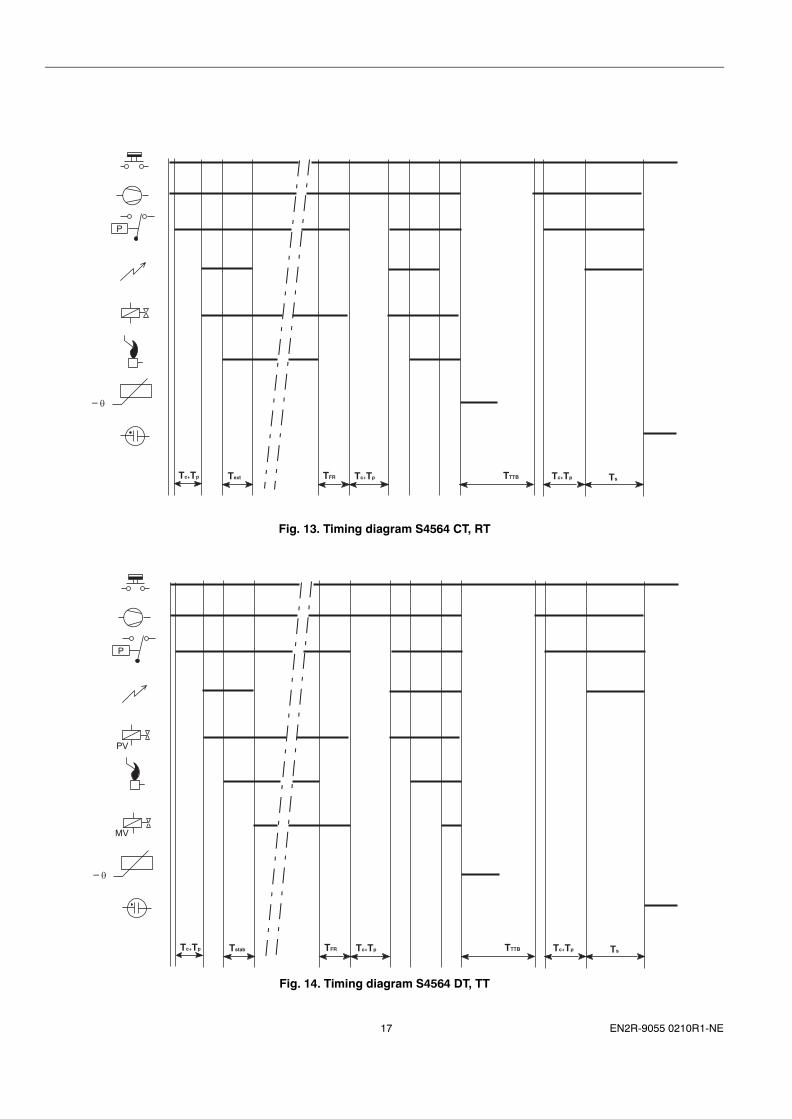
S4564 suffix CT and RT (seeFigure 13.)When there is a call for heat, the fan output is energised if the APS is in the normally closed position. As soon a the APS switches, the prepurge time (Tp) starts. After Tp the built-in igniter and gas valve are switched on.The ignition spark ignites gas and resulting flame is detected by the flame rod.If flame is established, ignition is switched off after an extended ignition time (Text).If flame is not established within the safety time (Ts), the ignition control locks out and the fan is deenergised. When the APS drops back, the alarm indicator is on.If the flame is lost during normal run, the gas valve closes after the flame failure response time (TFR) and the ignition control repeats start sequence. If the flame disappears during a period shorter than TFR, no reaction will follow.If the resistance value of the NTC sensor drops below the threshold, then the gas valve is switched off.After a predetermined anti-cycle time (TTBB), the ignition control restarts if the sensor resistance is above the threshold.Fan starts, APS switches and the prepurge time (Tp) elapses before the built-in igniter and gas valve are switched on.
S4564 suffix C and RAs CT and RT but without Aquastat action.
S4564 suffix DT and TT (IP application seeFigure 14 )For IP applications, the flame relay is internally wired to the main gas valve. The main valve will be energised if the pilot valve is energised and a flame is present.When there is a call for heat, the fan output is energised if the APS is in the normally closed position. As soon a the APS switches, the prepurge time (Tp) starts. After Tp the the built-in igniter and the pilot gas valve are switched on.The ignition spark ignites pilot gas and resulting flame is detected by the flame rod.If flame is established, then after the stabilisation time (Tstab), the main valve is switched on and ignition is switched off.If flame is not established within the safety time (Ts), the ignition control locks out and the fan is deenergised. When the
15 EN2R-9055 0210R1-NE
APS drops back, the alarm indicator is on.If the flame is lost during normal run, the gas valve closes after the flame failure response time (TFR) and the ignition control repeats start sequence. If the flame disappears during a period shorter than TFR, no reaction will follow.If the resistance value of the NTC sensor drops below the threshold, the pilot gas valve and main gas valve are switched off.After a predetermined anti-cycle time (TTBB), the ignition control restarts if the sensor resistance is above the threshold.Fan starts, APS switches and the prepurge time (Tp) elapses before the built-in igniter and gas valve are switched on.
S4564 suffix DF and TF (IP application)As DT and TT but without Aquastat action.
S4564 suffix D or T (DBI application)For DBI application, the flame relay or flame opto is wired to the connector pin 1, 2 and optionally 3. The flame relay can be used to switch an external igniter, using the common and normally closed contact of the relay.Program sequence is identical as described for DT, TT, reading flame output instead of main valve and reading extended spark time instead of stabilisation time.
Lock-out and resetIf no flame is detected within the safety time, the ignition control locks out. The alarm neon and/or alarm output are energised.Unless permanent alarm indication is present, the alarm neon and/or output are deenergised when the call for heat is switched off.The S4564AT and BT ignition controls can be reset from lock-out by pressing the internal or external reset button.The S4564PT and QT ignition controls reset directly after switching the mains voltage (permanent live) off.
NOTE 4: If during normal use (flame detected and no sparking) the reset button is pressed, the gasvalves are switched off. The ignition control immediately starts a new sequence after releasing the reset button.
NOTE 5: After lock-out, a recovery time of 15 seconds is present. After that, reset is possible. With permanent alarm indication, this recovery time starts immediately after lock-out. Without permanent alarm indication this time starts when call for heat is present.
NOTE 6: After a reset an extended waiting time will occur, dependent on the value of safety time and extended spark time/stabilisation time. For Ts = 55 s and Tstab = 6 s, this is nominal 55 s.
NOTE 7: For fan assisted version, no reset is possible if during lock-out the fan of APS is disconnected !
LPG valve and gas pressure switchThe LPG valve is energised when a call for heat is present and the ignition control is not in lock-out.If the gas pressure switch closes, the self check and/or waiting time start.It is not adviesd to use an LPG valve together with permanent alarm. A small current will flow through the LPG valve if no call for heat is present due to an internal resistor that is parallel to the call for heat thermostat. The gas pressure switch is placed between the mains neutral and the neutral connection of the ignition control.
NOTE 8: If the control is in lock-out and the gas pressure switch opens (after a certain time), it is possible to reset from lock-out as long as the LPG valve stays connected.
NOTE 9: The gas pressure switch mentioned in this document is only a functional device. If it is not used, it must be bridged.
NOTE 10: It is not possible to connect an LPG valve to an ignition control with volatile lock-out (P, Q, R, T).
High limit operationA high limit thermostat can be connected to the ignition controls. It is wired in the neutral line of the gas valve(s).If during operation the high limit opens, the gas valve(s) shut down. (The LPG valve stays energised). Flame is lost and the ignition control repeats the start sequence. Assuming the high limit does not reset itself within the safety time, the ignition control goes to lock-out.
NOTE 11: If an automatic return high limit is connected as shown in the connection diagrams, the appliance must be such, that the high limit has a reset time sufficiently longer than the safety time. With long safety times in IP applications, this might be critical.
NOTE 12: If the appliance requires a limiter, then it must be connected between pin 13 and pin 14 of the Molex connector (pin 10 and 11 of the RAST5). Only if the OS number has phase dependent flame detection, it is allowed to connect the limiter in series with the call for heat thermostat (pin 5 of the Molex connector).
TTB/Aquastat OperationIf the sensed temperature exceeds the trip level, the ignition control is shut down. Valve(s) and fan will drop off and no further call for heat will be answered. (The LPG valve stays energised).NTC sensor short or NTC sensor open also causes TTB/Aquastat shutdown.If the TTB/Aquastat shutdown time has ended and the temperature is below the trip point and the call for heat is present, program run starts with self check time and/or waiting time. For the aquastat function, this shutdown time functions as an anti-cycle time.If the TTB/Aquastat shutdown time has ended and the temperature is below the trip point and no call for heat is present, the ignition control is waiting for the next call for heat.If the TTB/Aquastat shutdown time has ended and the temperature is still above the trip point, the TTB/Aquastat shutdown time is continued until the sensor temperature drops below the trip level.
NOTE 13: If during the TTB/Aquastat shutdown time the mains is switched off longer than 10 seconds, then the TTB/Aquastat timer is reset. Wait at least 10 seconds to switch the mains on again, otherwise the TTB/Aquastat timer continues and the ignition control starts only after the TTB/Aquastat shutdown time.
NOTE 14: The TTB/Aquastat timer does not end nor reset when the call for heat is ended. The TTB/Aquastat timer is seperately supplied by the permanent live.
NOTE 15: If the permanent live connection is not present, the ignition control stays in TTB/Aquastat shutdown.
EN2R-9055 0210R1-NE16
Fig. 11. Timing diagram S4564 AT, PT
Fig. 12. Timing diagram S4564 BT, QT
Text Tc+Tw TsTFRText Tc+Tw TTTB
_ θ
Tc+Tw
LPG
Tstab Tc+Tw TsTFRTstab Tc+Tw TTTB
_ θ
Tc+Tw
LPG
MV
PV
17 EN2R-9055 0210R1-NE
Fig. 13. Timing diagram S4564 CT, RT
Fig. 14. Timing diagram S4564 DT, TT
Tc+Tp TsTFRText Tc+Tp TTTB
_ θ
Tc+Tp
P
Tc+Tp TsTFRTstab Tc+Tp TTTB
_ θ
P
MV
PV
Tc+Tp
EN2R-9055 0210R1-NE18
INSTALLATION, ADJUSTMENTS AND FINAL CHECKOUTInstallation
WARNINGTake care that the installer is a trained experienced service person.Disconnect power supply to prevent electrical shock and/or equipemnt damage.Turn off the gas supply before starting installation.After installation wait at least one hour before connecting the mains supply, because the device can have become wet due to condensation.Do not connect a wet device to mains!Honeywell is not responsible for damage and/or injury due to miswiring.
IMPORTANTBefore installing or replacing any control check that type number is correct for the application.Ensure that the combustion chamber is free of gas before start up.Conduct a thorough check out when installation is completed.
CAUTION Do not connect the ignition control to power supply when it is not connected to the gas control.
To ensure reliable long term operation, mount ignition control at a position in the appliance with a low ambient temperature and a low radiation. High temperatures will affect product life.
To suppress Radio Frequency Interference (RFI) the ignition control including spark igniter cabling should be mounted in sufficient shielded environment.
Electrical rating of connected controls (e.g. thermostat) should be appropriate for the load that is switched by the ignition control. (Valves).
NOTE 16: If the ignition control incorporates an EMC filter, disconnect the ignition control from mains before performing a dielectric strength test.
NOTE 17: When first starting, the ignition control can be in lock-out; reset the ignition control.If a first reset is not succesful, wait at least 15 seconds before attempting another one. After a reset an extended waiting time will occur.
WiringWiring must be in accordance with local regulations.The appliance manufacturer's instructions should always be followed when provided. If such instructions are not provided see the connection diagrams for typical systems.
Use cable which can withstand 105 °C ambient.Use cable which is proven against moisture.
Wiring between ignition control and flame sensing probe must be suitable for the temperatures encountered.
Wiring between the ignition control and the flame sensing probe must have a minimum isolation resistance to earth of 500 MΩ under all working conditions.
Wiring between ignition control and flame sensing probe must be one piece without means for interrupting.
NOTE 18: Both the flame sensing connection and NTC sensor connection are accessible parts according to EN 60730. If the ignition frequency is < 25 Hz, the high voltage spark connection is accessible according to EN 60730.
CAUTIONIf ignition frequency > 25 Hz or in case of combined ignition and flame sensing, the ignition cable and its connections shall have a protection against shock hazard.
Spark gapMax. allowable spark gap 3.5 mm.
High voltageMake sure that the clearance and creepage distance from any metal part of the high voltage connection to earth metal is more than 12 mm.
EMC guidelinesThe electronic ignition is a source of mains interference and radio frequency interference (RFI).In order to minimise RFI, do not lead the ignition wires close to mains wires and position them close to eartn metal.
Supply voltage polarityIf an ignition control (without the phase-neutral independent operation feature) seems to operate normally but does not detect flame, check for right polarity of power supply (line, neutral).
Checking flame currentThe minimum value should be in accordance with the specified value.
To check flame current connect a DC micro-Ampèremeter between flame sensing wire and flame sensing rod.Meter connections polluted with e.g. alkaline substances lying close to earth can cause flame current simulation.Make sure no false flame current can flow from meter connections to earth.
If flame current is insufficient check that flame sensing rod is fully enveloped by the flame.If there is not sufficient flame current due to phase-phase mains it is recommendable to use a S4564AT, BT, PT, QT ignition control with the phase-neutral independent operation feature.
Another solution is to use a AT7030A or AT7030B flame detection transformer. See also EN1R-9136 (instruction sheet of AT7030).
WARNINGShort µA meter during ignition to prevent damage of the µA meter in single rod application.
Final checkout of the installationSet appliance in operation after any adjustment and observe several complete cycles to ensure that all burner components function correctly. Check all the safety functions.Also check the functioning of the NTC sensor.

19 EN2R-9055 0210R1-NE
Maintenance and serviceUnder normal conditions no maintenance or service is required. The unit is field replaceable.
EN2R-9055 0210R1-NE20
QUALITY ASSURANCE STATEMENTProducts are manufactured under an ISO9001 (BS 5750/1 1987, part 1, EN 29001) based and certified Quality System.The quality system is described in the Honeywell Combustion Controls Centre Quality Assurance Programme and its related operational procedures and instructions.
The quality system is approved by Britisch Standards Institution (BSI) against certificate number FM 6 and is reviewed twice a year by BSI.
The quality organisation is responsible for defining, maintaining, improving and verification of the quality systems in the field of design, production process and field quality service.
Assembly processes are guided by work instructions.Patrol inspections form part of the assembly processes.Assembly inspection is performed by employees of the quality control department, using their own authorised equipment.All inspections (incoming and assembly) are performed by trained personel and in accordance with inspection procedures.
21 EN2R-9055 0210R1-NE
STANDARDS AND APPROVALSStandardsThe S4564 A-Q,AT-QT ignition control meets the european standards:
EN 60730-1:Automatic electrical controls for household and similar use.
EN 55014: Emission requirement for household appliances and portable tools.
EN 55104: Immunity requirements for household appliances, tools, and similar apparatus.
EN 298: Automatic gas burner control systems.
Regarding electrical safety the ignition control can be used in appliances according to the european standard for household electrical requirements EN 60335-1.
The S4564 A-Q, AT-BT ignition control functions in accordance with EN298 clause 4:
S4564 A, AT code A/M/C/L/X/N
S4564 B, BT code A/T/C/L/X/N
S4564 P, PT code A/M/C/V/X/N
S4564 Q, QT code A/T/C/V/X/N
ApprovalsThe S4564 A-Q,AT-QT ignition control conforms with the following EC - directives:· Gas Appliance Directive (90/396/EEC)· Low Voltage Directive (72/23/EEC)· Electro Magnetic Compatibility Directive (89/336/EEC)
Conformity with Electro Magnetic Compatibility Directive regarding emmission for non industrial appliances can be assumed for selected O.S. numbers only. However, conformaty can only be declared for a specific appliance as one piece.For other O.S. numbers, additional suppression means may be needed in the appliance.Details per O.S. number can be found in the Approvals List.
EN2R-9055 0210R1-NE22
Home and Building ControlCombustion Control Center EuropeHoneywell BVPhileas Foggstraat 77821 AJ EmmenThe NetherlandsTel.: +31 (-)591 695911Fax: +31 (-) 591 695200http://europe.hbc.honeywell.com
ORDERING INFORMATIONIdentification of the deviceThe identification of the device is by Honeywell Ordering Specification (O.S.) number and date code.
PackingThe ignition controls are packed in a carton box according to the Honeywell standards.
When ordering specifyO.S. number of ignition control.