Embed Size (px)
Citation preview

NOTE! To the installer: Please make sure you provide this manual to the owner of the equip ment or to the responsible party who maintains the system.
MODELS 1750 and 3450 RPM – S3W, S3WR SERIESSUBMERSIBLE SEWAGE PUMPSINSTALLATION AND SERVICE MANUALSingle and dual seal. Single and three phase power.
Item # E-03-555 | Part # 5625-555-1 | © 2014 Pentair Ltd. | 03/03/14
S3WRS3W

2
General InformationThank you for purchasing your Hydromatic® product. To help ensure years of trouble-free op er a tion, please read the fol low ing manual carefully.WARNING: Only qualified personnel shall install or service this product.
Before Operation: Read the following in structions care ful ly. Reasonable care and safe meth ods should be practiced. Check the local codes and requirements before installation.
Attention: This manual contains important information for the safe use of this product. Read this manual completely before using this product and refer to it often for con tin ued safe product use. DO NOT THROW AWAY THIS MAN U AL. Keep it in a safe place so that you may refer to it often.WARNING: Before handling electrical equipment, always disconnect the power first. Do not smoke or use sparkable electrical devices or flames in a septic (gaseous) or possible septic sump.
Safety WarningsFailure to heed these warnings and follow the instructions in this manual may result in severe bodily injury or death, or substantial property damage.
DO NOT wear loose clothing that can become entangled in the impeller or other moving parts.This pump is designed to handle materials that could cause illness or disease through direct exposure. Wear adequate protective clothing when working on the pump or piping.
NEVER operate a pump with a power cord that has frayed or brittle insulation.
NEVER let cords or plug lie in water. NEVER handle connected power cords with wet hands.
9. DO NOT use in swimming pools, decorative fountains or any installation where human contact with pumped fluid is common.
10. Do not operate pump without safety devices in place.
CALIFORNIA PROPOSITION 65 WARNING:
This product and related accessories contain chemicals known to the State of California to cause cancer, birth defects or other reproductive harm.
IMPORTANT! Hydromatic is not responsible for losses, injury or death resulting from a failure to observe these safety precautions, misuse or abuse of pumps or equipment.
General Description and ApplicationThe S3W and S3WR series sewage pumps are available in both a single seal and dual seal with leak detector and in 1750 RPM and 3450 RPM models. They are designed for raw sewage applications. These units can also be used for sump and general dewatering applications where larger solids capabilities are required.
These pumps are available in single and three phase. All three phase units, all dual seal units and all duplex installations must be used with a control box.
Air VentingUpon initial filling of wet well with water, air may be trapped in the pump volute. To vent off this air a 5/32" diameter hole is located in volute. BE SURE THIS VENT HOLE IS CLEAN AFTER ANY SERVICE WORK ON PUMP.
WARNING: RISK OF ELECTRICAL SHOCK! Single phase pumps are supplied with a grounding conductor and grounding-type attachment plug on the power cord. To reduce risk of electrical shock, be certain that it is connected only to a properly grounded, grounding-type receptacle. DO NOT cut off ground pin or use an adapter fitting. DO NOT use an extension cord with this pump.
Follow all local electrical and safety codes and ordinances as well as the most recent National Electric Code (NEC-ANSI/NFPA 70).
All pumps have a GROUND WIRE that is connected to a screw in the metal motor housing. This wire goes to the receptacle or control box which must be connected to a good outside GROUND such as a metal water pipe or GROUND STAKE driven at least 8 feet into the ground.
Pumps
1. Pumps build up heat and pressure during operation. Allow time for pump to cool before handling or servicing.
2. Only qualified personnel should install, operate or repair pump.
3. Keep clear of suction and discharge openings. DO NOT insert flingers in pump with power connected.
4. This pump MUST NOT be used to pump flammable, combustible or hazardous liquids. Make sure lifting handles are securely fastened each time before lifting.
5. DO NOT lift pump by power cord.
6. DO NOT exceed manufacturer’s recommendation for max. performance, as this could cause the motor to overheat.
7. ALWAYS secure the pump in its operating position so it cannot tip over, fall or slide.
8. Keep hands and feet away from impeller when power is connected.
3
Level ControlsAll pumps must use sealed level control switches for automatic operation.
Simplex single phase pumps can be made automatic by attaching MFS controls to the pump or discharge pipe. These switches have a fixed draw-off level of 8 to 10 inches and can be used up to 1 HP. Simplex and higher horsepower systems may also use on/off pilot control switches (SMNO) with control box and magnetic starter. The ALC and AWS-1 controls can be used for simplex single phase pumps with ratings up to 2 HP. All duplex systems must use pilot control switches (SNMO) with control box and magnetic starters.
Plug-in cords can be used on all the single phase pumps with a single seal (does not have seal leak detector). This cord has a GROUND pin that plugs into a grounded receptacle. The grounded receptacle cannot be used in the wet sumps or basin due to DANGER of current leakage. Sealed junction boxes must be used in wet sumps or basins to make connections to motor cord. The AWS-1 control also acts as a sealed junction box for connecting power cord to pump cord.
Dual Seal PumpsDual seal units are all made with a seal leak detector. The leak detector in the oil seal chamber detects a water leakage into the chamber and turns on a red signal light in the control panel. Control panels must be used for pumps having the seal leak detectors, and seal leak must be wired.
Pump Motor TypeMotors are ¾ frame 1, 1½, 2 and 3 HP single or three phase, 60 hertz, 1750 & 3450 RPM with class B insulation. All single phase motors are permanent split-capacitor (PSC) type with built-in winding overload protection and do not require a start switch or start relay. The three phase pump motors require
a magnetic starter with 3 leg overload protection. All motors have upper and lower ball bearings and all are oil-cooled and lubricated.
Pump InstallationWARNING: Basin or tank must be vented in accordance with local plumbing codes. These pumps are not designed for and CANNOT be installed in locations classified as hazardous in accordance with the National Electric Code ANSI/NFPA 70.
CAUTION: Never enter pump chamber after sewage or effluent has been in basin. Sewage water can give off methane, hydrogen sulfide and other gases that are highly poisonous. For this reason, Hydromatic recommends installing the S3W and S3WR series sewage pumps with a quick removal system. The quick removal system may be a union or Camlok® coupling if the pipe or discharge hose is within reach from the surface, or a rail system type quick disconnect on deeper installations.
The dosing tank or pumping chamber must be constructed of corrosion resistant materials and must be capable of withstanding all anticipated internal and external loads. It also must not allow infiltration or exfiltration. The tank must also have provisions for anti-buoyancy. Access holes or covers must be of adequate size and be accessible from the surface to allow installation and maintenance of the system. ACCESS COVERS MUST BE LOCKABLE OR HEAVY ENOUGH TO PREVENT EASY ACCESS TO UNAUTHORIZED PERSONNEL. The pumping chamber holding capacity should be selected to allow for emergency conditions.
The discharge pipe must be the same size as the pump discharge (3 inches) or larger. In order to ensure sufficient fluid velocity to prevent any residual solids from collecting in the discharge pipe, it is recommended that a minimum flow of 2 feet per second be maintained (46 gpm through 3" pipe).
It is recommended that a PVC or equal pipe is used for corrosion resistance. A full flow (ball or gate) shut-off valve must be installed to prevent back flow of sewage if the pump must be removed for service. A CHECK VALVE MUST BE INSTALLED ON PRESSURE SEWER SYSTEMS and on other systems where conditions allow to prevent back flow and to reduce wear on the pump system.
A high water alarm must be installed on a separate circuit from the pump circuit. The alarm should have the ability to be tested for proper operation.
Special Instructions for Three Phase Pumps 1. Hydromatic recommends three
phase pumps to be installed by qualified personnel. CAUTION: RISK OF ELECTRICAL SHOCK! Do not remove cord and strain relief. DO NOT connect conduit to pump.
2. Three phase pumps are always installed with control boxes having magnetic starters with 3-leg overload protections. DO NOT TRY TO RUN THREE PHASE PUMPS DIRECTLY ACROSS THE LINE.
3. To Connect Pump: Run wire from pump to bottom of control box or appropriate junction box suitable for enclosing splice connections. A hole must be cut into the control box for the wires. With power on control box OFF, connect green (ground) line to ground lug. Connect black (power) wires to power lead terminals. Note: For a typical CE style control box, these terminals are M1, M2 and M3. Make sure that all wires are inside control box and not in a position to be pinched or shorted when door is closed.
4
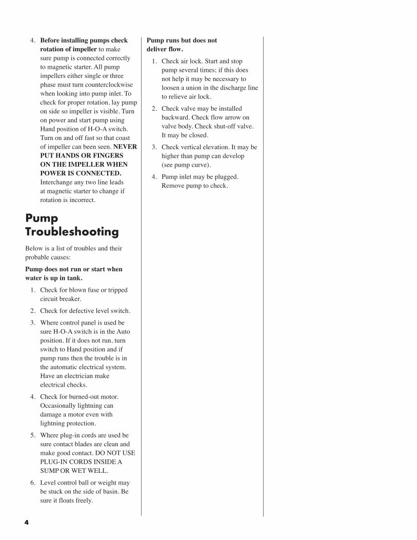
Pump runs but does not deliver flow.
1. Check air lock. Start and stop pump several times; if this does not help it may be necessary to loosen a union in the discharge line to relieve air lock.
2. Check valve may be installed backward. Check flow arrow on valve body. Check shut-off valve. It may be closed.
3. Check vertical elevation. It may be higher than pump can develop (see pump curve).
4. Pump inlet may be plugged. Remove pump to check.
4. Before installing pumps check rotation of impeller to make sure pump is connected correctly to magnetic starter. All pump impellers either single or three phase must turn counterclockwise when looking into pump inlet. To check for proper rotation, lay pump on side so impeller is visible. Turn on power and start pump using Hand position of H-O-A switch. Turn on and off fast so that coast of impeller can been seen. NEVER PUT HANDS OR FINGERS ON THE IMPELLER WHEN POWER IS CONNECTED. Interchange any two line leads at magnetic starter to change if rotation is incorrect.
Pump TroubleshootingBelow is a list of troubles and their probable causes:
Pump does not run or start when water is up in tank.
1. Check for blown fuse or tripped circuit breaker.
2. Check for defective level switch.
3. Where control panel is used be sure H-O-A switch is in the Auto position. If it does not run, turn switch to Hand position and if pump runs then the trouble is in the automatic electrical system. Have an electrician make electrical checks.
4. Check for burned-out motor. Occasionally lightning can damage a motor even with lightning protection.
5. Where plug-in cords are used be sure contact blades are clean and make good contact. DO NOT USE PLUG-IN CORDS INSIDE A SUMP OR WET WELL.
6. Level control ball or weight may be stuck on the side of basin. Be sure it floats freely.

5
6
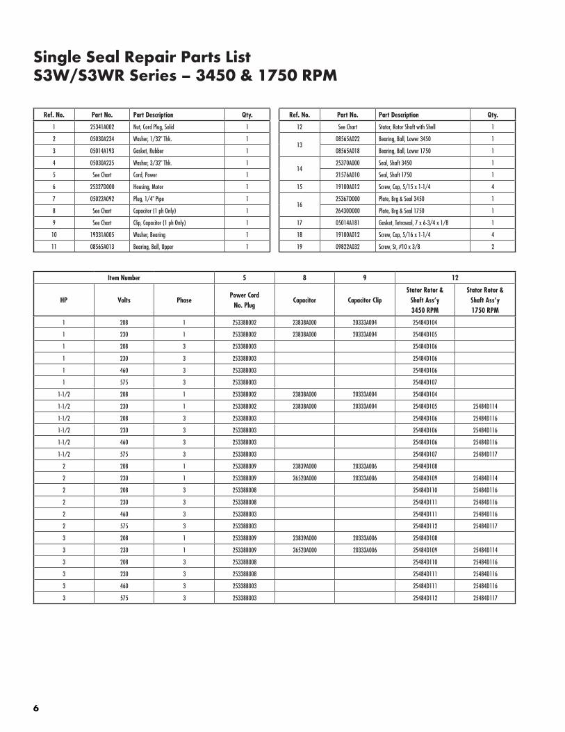
Single Seal Repair Parts List S3W/S3WR Series – 3450 & 1750 RPM
Ref. No. Part No. Part Description Qty.
1 25341A002 Nut, Cord Plug, Solid 1
2 05030A234 Washer, 1/32" Thk. 1
3 05014A193 Gasket, Rubber 1
4 05030A235 Washer, 3/32" Thk. 1
5 See Chart Cord, Power 1
6 25327D000 Housing, Motor 1
7 05022A092 Plug, 1/4" Pipe 1
8 See Chart Capacitor (1 ph Only) 1
9 See Chart Clip, Capacitor (1 ph Only) 1
10 19331A005 Washer, Bearing 1
11 08565A013 Bearing, Ball, Upper 1
Ref. No. Part No. Part Description Qty.
12 See Chart Stator, Rotor Shaft with Shell 1
1308565A022 Bearing, Ball, Lower 3450 1
08565A018 Bearing, Ball, Lower 1750 1
1425370A000 Seal, Shaft 3450 1
21576A010 Seal, Shaft 1750 1
15 19100A012 Screw, Cap, 5/15 x 1-1/4 4
1625367D000 Plate, Brg & Seal 3450 1
26430D000 Plate, Brg & Seal 1750 1
17 05014A181 Gasket, Tetraseal, 7 x 6-3/4 x 1/8 1
18 19100A012 Screw, Cap, 5/16 x 1-1/4 4
19 09822A032 Screw, St, #10 x 3/8 2
Item Number 5 8 9 12
HP Volts PhasePower Cord
No. PlugCapacitor Capacitor Clip
Stator Rotor &Shaft Ass’y3450 RPM
Stator Rotor &Shaft Ass’y1750 RPM
1 208 1 25338B002 23838A000 20333A004 25484D104
1 230 1 25338B002 23838A000 20333A004 25484D105
1 208 3 25338B003 25484D106
1 230 3 25338B003 25484D106
1 460 3 25338B003 25484D106
1 575 3 25338B003 25484D107
1-1/2 208 1 25338B002 23838A000 20333A004 25484D104
1-1/2 230 1 25338B002 23838A000 20333A004 25484D105 25484D114
1-1/2 208 3 25338B003 25484D106 25484D116
1-1/2 230 3 25338B003 25484D106 25484D116
1-1/2 460 3 25338B003 25484D106 25484D116
1-1/2 575 3 25338B003 25484D107 25484D117
2 208 1 25338B009 23839A000 20333A006 25484D108
2 230 1 25338B009 26520A000 20333A006 25484D109 25484D114
2 208 3 25338B008 25484D110 25484D116
2 230 3 25338B008 25484D111 25484D116
2 460 3 25338B003 25484D111 25484D116
2 575 3 25338B003 25484D112 25484D117
3 208 1 25338B009 23839A000 20333A006 25484D108
3 230 1 25338B009 26520A000 20333A006 25484D109 25484D114
3 208 3 25338B008 25484D110 25484D116
3 230 3 25338B008 25484D111 25484D116
3 460 3 25338B003 25484D111 25484D116
3 575 3 25338B003 25484D112 25484D117
7
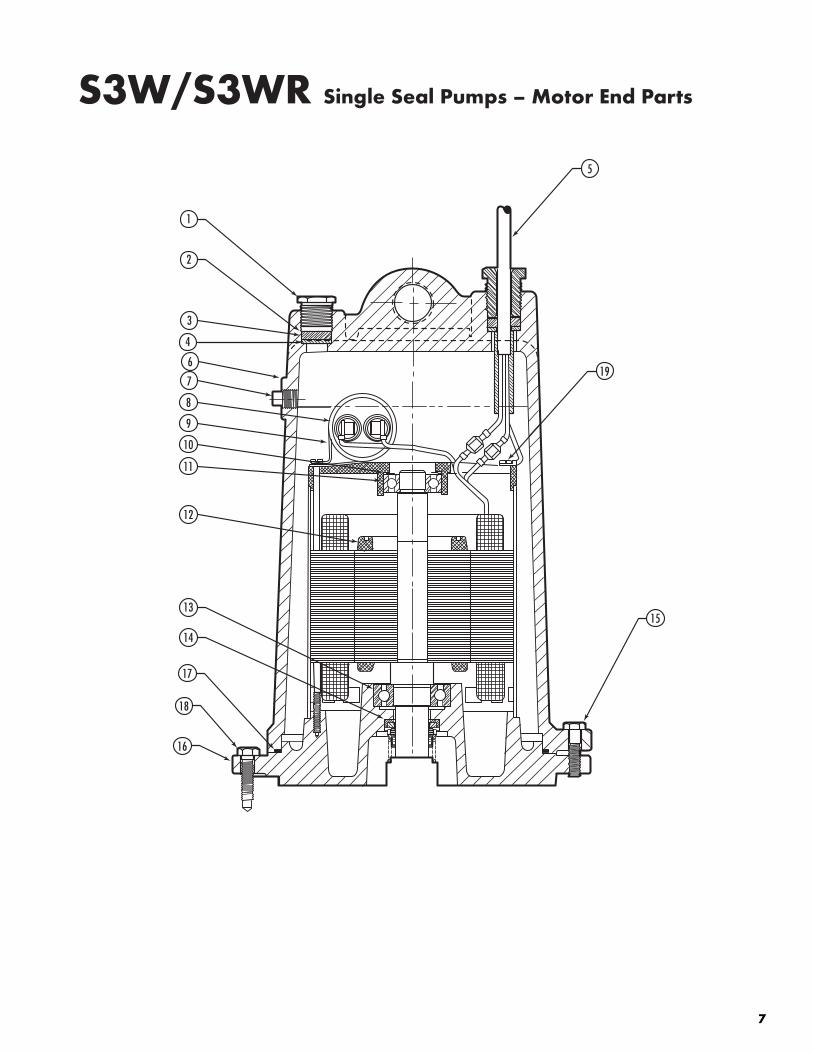
S3W/S3WR Single Seal Pumps – Motor End Parts
1
2
3
4
6
7
8
9
10
11
12
13
14
17
18
16
15
19
5

8
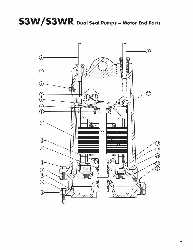
Dual Seal Repair Parts List S3W/S3WR Series – 3450 & 1750 RPM
Ref. No. Part No. Part Description Qty.
1 25339B000 Cord, Sensor 1
2 See Chart Cord, Power 1
3 25327D000 Housing, Motor 1
4 05022A092 Plug, 1/4" Pipe 1
5 See Chart Capacitor (1 ph Only) 1
6 See Chart Clip, Capacitor (1 ph Only) 1
7 19331A005 Washer, Bearing 1
8 08565A013 Bearing, Ball, Upper 1
9 See Chart Stator, Rotor Shaft with Shell 1
1008565A022 Bearing, Ball, Lower 3450 1
08565A018 Bearing, Ball, Lower 1750 1
1125370A000 Seal, Shaft 3450 2
21576A010 Seal, Shaft 1750 2
Ref. No. Part No. Part Description Qty.
12 19100A012 Screw, Cap, 5/16 x 1-1/4 4
1325369D000 Housing, Seal 3450 1
25369D001 Housing, Seal 1750 1
14 05014A181 Gasket, Tetraseal, 7 x 6-3/4 x 1/8 2
15 19100A012 Screw, Cap, 5/16 x 1-1/4 4
1625368D000 Lower, Seal Plate 3450 1
26476D000 Lower, Seal Plate 1750 1
17 09822A032 Screw, St, #10 x 3/8 2
18 21792A004 Wire Electrode 2
19 05434A025 Screw Machine #6 x 1/4 2
20 25343A000 Probe, Seal Leak 2
Item Number 2 5 6 9
HP Volts PhasePower Cord
No. PlugCapacitor Capacitor Clip
Stator Rotor &Shaft Ass’y3450 RPM
Stator Rotor &Shaft Ass’y1750 RPM
1 208 1 25338B002 23838A000 20333A004 25484D204
1 230 1 25338B002 23838A000 20333A004 25484D205
1 208 3 25338B003 25484D206
1 230 3 25338B003 25484D206
1 460 3 25338B003 25484D206
1 575 3 25338B003 25484D207
1-1/2 208 1 25338B002 23838A000 20333A004 25484D204
1-1/2 230 1 25338B002 23838A000 20333A004 25484D205 25484D214
1-1/2 208 3 25338B003 25484D206 25484D216
1-1/2 230 3 25338B003 25484D206 25484D216
1-1/2 460 3 25338B003 25484D206 25484D216
1-1/2 575 3 25338B003 25484D207 25484D217
2 208 1 25338B009 23839A000 20333A006 25484D208
2 230 1 25338B009 26520A000 20333A006 25484D209 25484D214
2 208 3 25338B008 25484D210 25484D216
2 230 3 25338B008 25484D211 25484D216
2 460 3 25338B003 25484D211 25484D216
2 575 3 25338B003 25484D212 25484D217
3 208 1 25338B009 23839A000 20333A006 25484D208
3 230 1 25338B009 26520A000 20333A006 25484D209 25484D214
3 208 3 25338B008 25484D210 25484D216
3 230 3 25338B008 25484D211 25484D216
3 460 3 25338B003 25484D211 25484D216
3 575 3 25338B003 25484D212 25484D217
9
1
3
4
5
6
7
8
9
10
11
12
13
14
15
16
4
14
20
19
18
17
2
S3W/S3WR Dual Seal Pumps – Motor End Parts
10
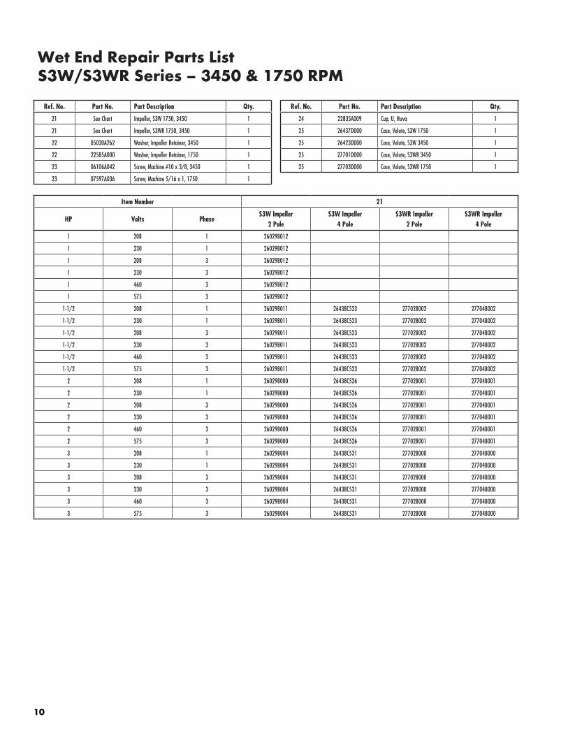
Wet End Repair Parts List S3W/S3WR Series – 3450 & 1750 RPM
Ref. No. Part No. Part Description Qty.
21 See Chart Impeller, S3W 1750, 3450 1
21 See Chart Impeller, S3WR 1750, 3450 1
22 05030A262 Washer, Impeller Retainer, 3450 1
22 22585A000 Washer, Impeller Retainer, 1750 1
23 06106A042 Screw, Machine #10 x 3/8, 3450 1
23 07597A036 Screw, Machine 5/16 x 1, 1750 1
Ref. No. Part No. Part Description Qty.
24 22835A009 Cup, U, Huva 1
25 26437D000 Case, Volute, S3W 1750 1
25 26423D000 Case, Volute, S3W 3450 1
25 27701D000 Case, Volute, S3WR 3450 1
25 27703D000 Case, Volute, S3WR 1750 1
Item Number 21
HP Volts PhaseS3W Impeller
2 PoleS3W Impeller
4 PoleS3WR Impeller
2 PoleS3WR Impeller
4 Pole
1 208 1 26029B012
1 230 1 26029B012
1 208 3 26029B012
1 230 3 26029B012
1 460 3 26029B012
1 575 3 26029B012
1-1/2 208 1 26029B011 26438C523 27702B002 27704B002
1-1/2 230 1 26029B011 26438C523 27702B002 27704B002
1-1/2 208 3 26029B011 26438C523 27702B002 27704B002
1-1/2 230 3 26029B011 26438C523 27702B002 27704B002
1-1/2 460 3 26029B011 26438C523 27702B002 27704B002
1-1/2 575 3 26029B011 26438C523 27702B002 27704B002
2 208 1 26029B000 26438C526 27702B001 27704B001
2 230 1 26029B000 26438C526 27702B001 27704B001
2 208 3 26029B000 26438C526 27702B001 27704B001
2 230 3 26029B000 26438C526 27702B001 27704B001
2 460 3 26029B000 26438C526 27702B001 27704B001
2 575 3 26029B000 26438C526 27702B001 27704B001
3 208 1 26029B004 26438C531 27702B000 27704B000
3 230 1 26029B004 26438C531 27702B000 27704B000
3 208 3 26029B004 26438C531 27702B000 27704B000
3 230 3 26029B004 26438C531 27702B000 27704B000
3 460 3 26029B004 26438C531 27702B000 27704B000
3 575 3 26029B004 26438C531 27702B000 27704B000
11
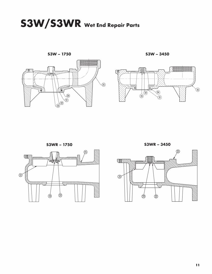
Wet End Repair PartsS3W – 1750
2322
21
24
25
S3W – 3450
2322
21
2425
S3WR – 1750 S3WR – 3450
2223
21
25
2223
21
25
S3W/S3WR Wet End Repair Parts
740 EAST 9TH STREET 490 PinEbuSH RoAd, uniT #4 ASHLAnd, oHio, uSA 44805 CAMbRidGE, onTARio, CAnAdA n1T 0A5 419-289-1144 800-363-PuMP
WWW.HYdRoMATiC.CoM
Warranty Rev. 12/13
STANDARD LIMITED WARRANTY
Pentair Hydromatic® warrants its products against defects in material and workmanship for a period of 12 months from the date of shipment from Pentair Hydromatic or 18 months from the manufacturing date, whichever occurs first – provided that such products are used in compliance with the requirements of the Pentair Hydromatic catalog and technical manuals for use in pumping raw sewage, municipal wastewater or similar, abrasive-free, noncorrosive liquids.
during the warranty period and subject to the conditions set forth, Pentair Hydromatic, at its discretion, will repair or replace to the original user, the parts that prove defective in materials and workmanship. Pentair Hydromatic reserves the right to change or improve its products or any portions thereof without being obligated to provide such a change or improvement for prior sold and/or shipped units.
Start-up reports and electrical schematics may be required to support warranty claims. Submit at the time of start up through the Pentair Hydromatic website: http://forms.pentairliterature.com/startupform/startupform.asp?type=h. Warranty is effective only if Pentair Hydromatic authorized control panels are used. All seal fail and heat sensing devices must be hooked up, functional and monitored or this warranty will be void. Pentair Hydromatic will cover only the lower seal and labor thereof for all dual seal pumps. under no circumstance will Pentair Hydromatic be responsible for the cost of field labor, travel expenses, rented equipment, removal/reinstallation costs or freight expenses to and from the factory or an authorized Pentair Hydromatic service facility.This limited warranty will not apply: (a) to defects or malfunctions resulting from failure to properly install, operate or maintain the unit in accordance with the printed instructions provided; (b) to failures resulting from abuse, accident or negligence; (c) to normal maintenance services and parts used in connection with such service; (d) to units that are not installed in accordance with applicable local codes, ordinances and good trade practices; (e) if the unit is moved from its original installation location; (f) if unit is used for purposes other than for what it is designed and manufactured; (g) to any unit that has been repaired or altered by anyone other than Pentair Hydromatic or an authorized Pentair Hydromatic service provider; (h) to any unit that has been repaired using non factory specified/oEM parts.
Warranty Exclusions: PEnTAiR HYdRoMATiC MAKES no EXPRESS oR iMPLiEd WARRAnTiES THAT EXTEnd bEYond THE dESCRiPTion on THE FACE HEREoF. PEnTAiR HYdRoMATiC SPECiFiCALLY diSCLAiMS THE iMPLiEd WARRAnTiES oF MERCHAnTAbiLiTY And FiTnESS FoR AnY PARTiCuLAR PuRPoSE.
Liability Limitation: in no EVEnT SHALL PEnTAiR HYdRoMATiC bE LiAbLE oR RESPonSibLE FoR ConSEQuEnTiAL, inCidEnTAL oR SPECiAL dAMAGES RESuLTinG FRoM oR RELATEd in AnY MAnnER To AnY PEnTAiR HYdRoMATiC PRoduCT oR PARTS THEREoF. PERSonAL inJuRY And/oR PRoPERTY dAMAGE MAY RESuLT FRoM iMPRoPER inSTALLATion. PEnTAiR HYdRoMATiC diSCLAiMS ALL LiAbiLiTY, inCLudinG LiAbiLiTY undER THiS WARRAnTY, FoR iMPRoPER inSTALLATion. PEnTAiR HYdRoMATiC RECoMMEndS inSTALLATion bY PRoFESSionALS.
Some states do not permit some or all of the above warranty limitations or the exclusion or limitation of incidental or consequential damages and therefore such limitations may not apply to you. no warranties or representations at any time made by any representatives of Pentair Hydromatic shall vary or expand the provision hereof.