Embed Size (px)
Citation preview

Power and productivity
for a better worldTM
S200 I/OHardware


S200 I/OHardware

NOTICEThis document contains information about one or more ABB products and may include adescription of or a reference to one or more standards that may be generally relevant tothe ABB products. The presence of any such description of a standard or reference to astandard is not a representation that all of the ABB products referenced in this documentsupport all of the features of the described or referenced standard. In order to determinethe specific features supported by a particular ABB product, the reader should consult theproduct specifications for the particular ABB product.
ABB may have one or more patents or pending patent applications protecting the intel-lectual property in the ABB products described in this document.
The information in this document is subject to change without notice and should not beconstrued as a commitment by ABB. ABB assumes no responsibility for any errors thatmay appear in this document.
In no event shall ABB be liable for direct, indirect, special, incidental or consequentialdamages of any nature or kind arising from the use of this document, nor shall ABB beliable for incidental or consequential damages arising from use of any software or hard-ware described in this document.
This document and parts thereof must not be reproduced or copied without written per-mission from ABB, and the contents thereof must not be imparted to a third party nor usedfor any unauthorized purpose.
The software or hardware described in this document is furnished under a license andmay be used, copied, or disclosed only in accordance with the terms of such license. Thisproduct meets the requirements specified in EMC Directive 2004/108/EEC and in LowVoltage Directive 2006/95/EEC.
TRADEMARKSAll rights to copyrights, registered trademarks, and trademarks reside with their respec-tive owners.
Copyright © 2003-2010 by ABB. All rights reserved.
Release: June 2010Document number: 3BSE021356R4101 A

3BSE021356R4101 A 5
TABLE OF CONTENTS
Safety SummaryBe Careful – Prevent Accidents and Protect Valuable Equipment ..................................17
Before Replacing I/O Units .............................................................................................18
Maintenance ....................................................................................................................18
Operating Environment ...................................................................................................18
Important Software...............................................................................................19
Important Hardware .............................................................................................19
Signal Noise Due to Cables .............................................................................................19
Hazardous Electrical Supplies .........................................................................................19
Mandatory Installation Instructions.................................................................................19
About This BookGeneral ............................................................................................................................21
Safety .............................................................................................................21
How to Read the Manual......................................................................................21
Use of Warning, Caution, Information, and Tip Icons ....................................................22
Document Conventions ...................................................................................................23
Applicable Specifications ................................................................................................24
European Union Directive Compliance ...............................................................24
UL Listing ............................................................................................................24
CSA Certification.................................................................................................24

Table of Contents
6 3BSE021356R4101 A
Section 1 - IntroductionProduct Overview............................................................................................................ 25
The I/O Components............................................................................................ 26
Section 2 - System ConfigurationI/O System Connection ................................................................................................... 29
Terminal Base and I/O Unit Configuration ..................................................................... 30
Connecting the Power Supply Cables ............................................................................. 31
Using 200-PS1.3 to Supply the Remote I/O System ........................................... 32
Calculating the 24 V Supply to the I/O System .............................................................. 33
Section 3 - General Installation InstructionsInstallation Precautions ................................................................................................... 35
Power Installation............................................................................................................ 36
Installation of Power-Line Filter for 24 V DC..................................................... 41
Installation of External Cables ........................................................................................ 42
Recommended Cable Types................................................................................. 42
Connecting Power Supply Cables........................................................................ 42
Connecting Cables to Screw Terminals ............................................................... 43
Section 4 - Mounting InstructionsRails and Profiles ................................................................................................. 45
Mounting the Terminal Bases ......................................................................................... 46
Removing a Terminal Base Unit.......................................................................... 48
Mounting the Adapters.................................................................................................... 49
Checking the Basic (Internal) Mountings ....................................................................... 50
Setting the Terminal Base Code Keys ............................................................................. 51
Mounting the I/O Units ................................................................................................... 52
Mounting Cable 200-CE1 or 200-CE3 ........................................................................... 53
Mounting Cables when DIN Rails are Used........................................................ 53
Mounting Cables when Mounting Profiles are Used........................................... 55

Table of Contents
3BSE021356R4101 A 7
3BSE021356R4101 A 7
Section 5 - Functional DescriptionTerminal Base Unit Overview .........................................................................................57
Terminal Base Compatibility Cross Reference ....................................................58
Terminal Base Unit 200-TB2 ..........................................................................................60
Functional Description .........................................................................................61
Terminal Base Unit 200-TB3 ..........................................................................................63
Functional Description .........................................................................................64
Terminal Base Unit 200-TB3S ........................................................................................66
Functional Description .........................................................................................67
Terminal Base Unit 200-TB32 ........................................................................................69
Functional Description .........................................................................................70
Terminal Base Unit 200-TB3T ........................................................................................72
Functional Description .........................................................................................73
Terminal Base Unit 200-TBN..........................................................................................76
Functional Description .........................................................................................77
Terminal Base Unit 200-TBNF .......................................................................................79
Functional Description .........................................................................................80
Digital Input Unit 200-IB16 ............................................................................................82
Front Panel ...........................................................................................................82
Functional Description .........................................................................................82
200-IB16 Connections .........................................................................................84
Digital Output Unit 200-OB16........................................................................................86
Front Panel ...........................................................................................................86
Functional Description .........................................................................................87
200-OB16 Connections ........................................................................................88
Digital Output Unit 200-OB16P......................................................................................90
Front Panel ...........................................................................................................90
Functional Description .........................................................................................91
200-OB16P Connections......................................................................................92

Table of Contents
8 3BSE021356R4101 A
Digital Input/Output Combo Unit 200-IB10xOB6 ......................................................... 94
Front Panel ........................................................................................................... 94
Functional Description......................................................................................... 95
200-IB10xOB6 Connections................................................................................ 97
Digital Input Unit 200-IB32............................................................................................ 99
Front Panel ........................................................................................................... 99
Functional Description....................................................................................... 100
200-IB32 Connections ....................................................................................... 101
Digital Output Unit 200-OB32P ................................................................................... 103
Functional Description....................................................................................... 104
200-OB32P Connections ................................................................................... 106
Digital Input/Output Combo Unit 200-IB16xOB16P ................................................... 108
Front Panel ......................................................................................................... 109
Functional Description....................................................................................... 109
200-IB16xOB16P Connections ......................................................................... 111
Pulse Counter Unit 200-IP2 .......................................................................................... 113
Front Panel ......................................................................................................... 113
Functional Description....................................................................................... 114
200-IP2 Connections.......................................................................................... 126
Temperature Precautions.................................................................................... 130
Frequency Counter Unit 200-IP4 .................................................................................. 132
Front Panel ......................................................................................................... 132
Functional Description....................................................................................... 134
200-IP4 Connections.......................................................................................... 140
Temperature Precautions.................................................................................... 144
Analog Input Unit 200-IE8 ........................................................................................... 145
Front Panel ......................................................................................................... 145
Functional Description....................................................................................... 145
200-IE8 Connections ......................................................................................... 147

Table of Contents
3BSE021356R4101 A 9
3BSE021356R4101 A 9
Analog Output Unit 200-OE4 .......................................................................................149
Front Panel .........................................................................................................149
Functional Description .......................................................................................149
200-OE4 Connections ........................................................................................151
Input/Output Analog Combo Unit 200-IE4xOE2 .........................................................153
Front Panel .........................................................................................................153
Functional Description .......................................................................................153
200-IE4xOE2 Connections ................................................................................155
Analog Input Unit 200-IF4I...........................................................................................157
Front Panel .........................................................................................................157
Functional Description .......................................................................................158
200-IF4I Connections.........................................................................................160
Analog Output Unit 200-OF4I ......................................................................................162
Front Panel .........................................................................................................162
Functional Description .......................................................................................163
200-OF4I Connections .......................................................................................164
RTD Input Unit 200-IR8................................................................................................166
Front Panel .........................................................................................................166
Sensor Types ......................................................................................................167
Functional Description .......................................................................................167
Filter and Unit Throughput ................................................................................169
Unit Calibration Overview .................................................................................171
200-IR8 Connections .........................................................................................175
RTD Input Unit 200-IR8R.............................................................................................179
Front Panel .........................................................................................................179
Functional Description .......................................................................................180
200-IR8R Connections.......................................................................................183

Table of Contents
10 3BSE021356R4101 A
Thermocouple Input Unit 200-IT8................................................................................ 185
Front Panel ......................................................................................................... 185
Sensor Types ...................................................................................................... 186
Functional Description....................................................................................... 186
Filter and Unit Throughput ................................................................................ 187
Unit Calibration Overview................................................................................. 189
200-IT8 Connections ......................................................................................... 195
AC Input Unit 200-IA8 ................................................................................................. 198
Front Panel ......................................................................................................... 198
Functional Description....................................................................................... 198
200-IA8 Connections ......................................................................................... 200
AC Output Unit 200-OA8 ............................................................................................. 202
Front Panel ......................................................................................................... 202
Functional Description....................................................................................... 202
200-OA8 Connections........................................................................................ 204
AC Input Unit 200-IM8................................................................................................. 206
Front Panel ......................................................................................................... 206
Functional Description....................................................................................... 206
200-IM8 Connections ........................................................................................ 208
AC Output Unit 200-OM8 ............................................................................................ 210
Front Panel ......................................................................................................... 210
Functional Description....................................................................................... 210
200-OM8 Connections....................................................................................... 211
Relay Output Unit 200-OW8 ........................................................................................ 213
Front Panel ......................................................................................................... 213
Functional Description....................................................................................... 213
200-OW8 Connections....................................................................................... 215
Short-circuit Proof Output Unit 200-OB8EP................................................................ 217
Front Panel ......................................................................................................... 217
Functional Description....................................................................................... 218
200-OB8EP Connections ................................................................................... 220
Dummy Unit 200-DUTB .............................................................................................. 221

Table of Contents
3BSE021356R4101 A 11
3BSE021356R4101 A 11
Adapter for Central I/O System 200-ANN....................................................................222
Front Panel .........................................................................................................222
Functional Description .......................................................................................223
Adapter for Remote I/O System 200-ACN ...................................................................224
Front Panel .........................................................................................................225
Functional Description .......................................................................................226
LED Indications .................................................................................................227
Node Address Selection .....................................................................................228
Adapter for PROFIBUS 200-APB12.............................................................................229
Front Panel .........................................................................................................229
Functional Description .......................................................................................230
LED Indications .................................................................................................230
Node Address Selection .....................................................................................230
Screw Terminals .................................................................................................231
Adapter for Serial I/O Bus 200-AIO .............................................................................232
Power Supply for the Remote I/O System 200-PS1.3...................................................233
Front Panel .........................................................................................................233
Functional Description .......................................................................................234
I/O System Accessories .................................................................................................235
Cables ...........................................................................................................235
Clips ...........................................................................................................236

Table of Contents
12 3BSE021356R4101 A
Section 6 - Maintenance and ServiceReplacing I/O System Units.......................................................................................... 237
Changing Fuses ............................................................................................................. 238
Troubleshooting the I/O System.................................................................................... 239
General .......................................................................................................... 239
Troubleshooting 200-PS1.3 ............................................................................... 239
Troubleshooting 200-IB16................................................................................. 239
Troubleshooting 200-OB16 or 200-OB16P....................................................... 240
Troubleshooting 200-IB10xOB6 ....................................................................... 241
Troubleshooting 200-IB32................................................................................. 241
Troubleshooting 200-OB32P ............................................................................. 242
Troubleshooting 200-IB16xOB16P ................................................................... 243
Troubleshooting 200-IP2 ................................................................................... 243
Troubleshooting 200-IP4 ................................................................................... 244
Troubleshooting 200-IE8 ................................................................................... 245
Troubleshooting 200-OE4.................................................................................. 246
Troubleshooting 200-IE4xOE2.......................................................................... 246
Troubleshooting 200-IF4I .................................................................................. 247
Troubleshooting 200-OF4I ................................................................................ 248
Troubleshooting 200-IR8................................................................................... 249
Troubleshooting 200-IR8R ................................................................................ 250
Troubleshooting 200-IT8 ................................................................................... 250
Troubleshooting 200-IM8.................................................................................. 251
Troubleshooting 200-OM8 ................................................................................ 251
Troubleshooting 200-IA8................................................................................... 252
Troubleshooting 200-OA8 ................................................................................. 253
Troubleshooting 200-OW8 ................................................................................ 254
Troubleshooting 200-OB8EP............................................................................. 255
Troubleshooting 200-ANN ................................................................................ 256
Troubleshooting 200-ACN................................................................................. 257
Troubleshooting 200-APB12 ............................................................................. 259

Table of Contents
3BSE021356R4101 A 13
3BSE021356R4101 A 13
Appendix A - Technical SpecificationsGeneral Specifications ...................................................................................................261
Terminal Base Unit 200-TB2 ........................................................................................262
Terminal Base Unit 200-TB3 ........................................................................................263
Terminal Base Unit 200-TB3S ......................................................................................264
Terminal Base Unit 200-TB32 ......................................................................................265
Terminal Base Unit 200-TB3T ......................................................................................266
Terminal Base Unit 200-TBN........................................................................................267
Terminal Base Unit 200-TBNF .....................................................................................268
Digital Input Unit 200-IB16 ..........................................................................................269
Digital Output Unit 200-OB16......................................................................................271
Digital Output Unit 200-OB16P....................................................................................273
Digital Input/Output Combo Unit 200-IB10xOB6........................................................275
Digital Input Unit 200-IB32 ..........................................................................................277
Digital Output Unit 200-OB32P....................................................................................279
Digital Input/Output Combo Unit 200-IB16xOB16P ...................................................281
Pulse Counter Unit 200-IP2...........................................................................................284
Frequency Counter Unit 200-IP4 ..................................................................................286
Analog Input Unit 200-IE8............................................................................................288
Analog Output Unit 200-OE4 .......................................................................................290
Input/Output Analog Combo Unit 200-IE4xOE2 .........................................................292
Analog Input Unit 200-IF4I...........................................................................................294
Analog Output Unit 200-OF4I ......................................................................................296
RTD Input Unit 200-IR8................................................................................................298
RTD Input Unit 200-IR8R.............................................................................................301
Thermocouple Input Unit 200-IT8 ................................................................................304
AC Input Unit 200-IA8..................................................................................................307
AC Output Unit 200-OA8..............................................................................................309
AC Input Unit 200-IM8 .................................................................................................311
AC Output Unit 200-OM8.............................................................................................314
Relay Output Unit 200-OW8.........................................................................................316
Short-Circuit-Proof Output Unit 200-OB8EP ...............................................................319

Table of Contents
14 3BSE021356R4101 A
Dummy Unit 200-DUTB .............................................................................................. 321
Adapter for Central I/O System 200-ANN ................................................................... 322
Adapter for Remote I/O System 200-ACN ................................................................... 323
Adapter for ProfiBus 200-APB12 ................................................................................. 324
Adapter for Serial I/O bus 200-AIO.............................................................................. 325
Power Supply Unit 200-PS1.3 ...................................................................................... 326
I/O Accessories ............................................................................................................. 328
Cable 200-CE1................................................................................................... 328
Cable 200-CE3................................................................................................... 328
Cable TK210V005............................................................................................. 329
Cable TK210V010............................................................................................. 329
Cable TK210V025............................................................................................. 329
Mounting Profile MP990 ................................................................................... 330
Mounting Profile MP890 ................................................................................... 330
Mounting Profile MP590 ................................................................................... 330
Clips .......................................................................................................... 331
Appendix B - Recommended ComponentsPower-Line Filters ............................................................................................. 333
Grounding Devices ............................................................................................ 334
Devices for Extended Noise Suppression .......................................................... 334
Miscellaneous .................................................................................................... 338
Power Supplies................................................................................................... 339
Cables for Process Signals ................................................................................. 340
Table of Contents
3BSE021356R4101 A 15
3BSE021356R4101 A 15
Appendix C - Mounting DimensionsTerminal Base Unit ........................................................................................................341
I/O Unit..........................................................................................................................342
Adapter ..........................................................................................................................342
Power Supply 200-PS1.3 ...............................................................................................343
DIN Rail ........................................................................................................................343
Mounting Profile............................................................................................................344
Clips ............................................................................................................................345
Air Gap ..........................................................................................................................345
Split Rows......................................................................................................................346
Appendix D - StandardsCSA Hazardous Location Approval ..............................................................................347
Approbation d‘utilisation dans des emplacements dangereux par la CSA....................349
Appendix E - Directive ConsiderationsElectromagnetic Compatibility (EMC) .........................................................................351
Low-Voltage Directive (LVD) .......................................................................................351
INDEX

Table of Contents
16 3BSE021356R4101 A

3BSE021356R4101 A 17
Safety Summary
This section is mandatory reading for anyone planning to use the control system.
Be Careful – Prevent Accidents and Protect Valuable Equipment
A control system is a general tool which can be used in various processes. Responsibility for attaining and maintaining a reasonable level of safety must therefore rest with the people who engineer, operate and maintain the equipment. They must have intimate knowledge of the functions and inherent safety risks of the processes involved, and the imaginative power to anticipate situations in which accidents may occur.
Electrostatic Sensitive DeviceDevices labeled with this symbol require special handling precautions as described in the installation section.
GENERAL WARNINGS
Equipment EnvironmentAll components, whether in transportation, operation or storage, must be in a noncorrosive environment.
Electrical Shock Hazard During MaintenanceDisconnect power or take precautions to insure that contact with ener-gized parts is avoided when servicing.

Before Replacing I/O Units Safety Summary
18 3BSE021356R4101 A
Special attention should be paid to situations in which the mains supply is switched on or off, units are fitted or removed, cables are connected or disconnected, and units are reset or switched to manual operation. If possible, the process should be shut down before such actions are taken.
The level of safety can be improved considerably by taking steps to bring the process to a safe state when power supplies, communication links or parts of the control system fail. Such steps may, for instance, imply the installation of valves or relays which are spring-returned to a safe position.
Before Replacing I/O UnitsAlthough it is possible to remove and insert I/O system units, except adapters and terminal base units, under system power, it is highly recommended that the process side power be disconnected before removing or inserting an I/O unit to avoid hazardous conditions.
S200L I/O units must not be removed or inserted under system power, as hazardous conditions may occur or units may be damaged.
MaintenanceIn order to avoid long shutdowns, it is advisable to keep spares of components in stock.
Always make regular backup copies of the application program.
Operating EnvironmentBefore the system is brought on-line, find out which environmental conditions are applicable. The following points are important.
• The product must not be exposed to conditions exceeding the stated values in the technical specifications.
• The product must not be used in an environment where it is exposed to strong electrical interference. Electrical machines can produce interference which exceeds the permitted levels for the equipment, e.g. during repair work.
• All products must be handled with appropriate precautions with regard to electrostatic damage.

Safety Summary Important Software
3BSE021356R4101 A 19
Important Software
• Use the system’s fault-monitoring facility to prevent mishaps and accidents.
• Check possible consequences before executing any changes.
Important Hardware
Do not disconnect the power supply to a system which is in operation.
Signal Noise Due to CablesCables which might cause electrical interference (e.g. power-line cables) must not be installed close to bus cables carrying fast digital signals. Ensure a minimum distance of 100 mm (4 inches) between them inside cabinets.
Hazardous Electrical SuppliesOperations in which personnel may come into contact with high-voltage supplies should only be performed by those trained in the maintenance of electrical equipment and who are fully aware of the risks involved.
Mandatory Installation Instructions
Mandatory installation instructions in this document are marked with the symbol . Such instructions must be followed to fulfil the EMC directive.
M

Mandatory Installation Instructions Safety Summary
20 3BSE021356R4101 A

3BSE021356R4101 A 21
About This Book
GeneralThis manual is intended for those involved in the configuration, installation and maintenance of the S200 I/O system.
Safety
It is mandatory for all users of the control system to read the section Safety Summary before taking any action.
How to Read the Manual
The section Introduction provides an overview of the I/O system.
The section System Configuration is intended for those who will configure an I/O system. Alternative configurations and the methods for calculation of power consumption are discussed.
The sections General Installation Instructions and Mounting Instructions, give a step-by-step explanation of how to mount the I/O components and connect external cables to the system.
The section Functional Description describes the function and connections of the I/O units.
The last section Maintenance and Service is intended for maintenance and service engineers.
Appendices provide technical specifications, order codes, recommended components, mounting dimensions and Standards.

Use of Warning, Caution, Information, and Tip Icons About This Book
22 3BSE021356R4101 A
Use of Warning, Caution, Information, and Tip IconsThis publication includes Warning, Caution, and Information where appropriate to point out safety related or other important information. It also includes Tip to point out useful hints to the reader. The corresponding symbols should be interpreted as follows:
Although Warning hazards are related to personal injury, and Caution hazards are associated with equipment or property damage, it should be understood that operation of damaged equipment could, under certain operational conditions, result in degraded process performance leading to personal injury or death. Therefore, comply fully with all Warning and Caution notices.
Electrical warning icon indicates the presence of a hazard which could result in electrical shock.
Warning icon indicates the presence of a hazard which could result in personal injury.
Caution icon indicates important information or warning related to the concept disussed in the text. It might indicate the presence of a hazard which could result in corruption of software or damage to equipment/property.
Information icon alerts the reader to pertinent facts and conditions.
Tip icon indicates advice on, for example, how to design your project or how to use a certain function

About This Book Document Conventions
3BSE021356R4101 A 23
Document ConventionsThe following conventions are used for the presentation of material:
• The words in names of screen elements (for example, the title in the title bar of a window, the label for a field of a dialog box) are initially capitalized.
• Capital letters are used for the name of a keyboard key if it is labeled on the keyboard. For example, press the ENTER key.
• Lowercase letters are used for the name of a keyboard key that is not labeled on the keyboard. For example, the space bar, comma key, and so on.
• Press CTRL+C indicates that you must hold down the CTRL key while pressing the C key (to copy a selected object in this case).
• Press ESC E C indicates that you press and release each key in sequence (to copy a selected object in this case).
• The names of push and toggle buttons are boldfaced. For example, click OK.
• The names of menus and menu items are boldfaced. For example, the File menu.
– The following convention is used for menu operations: MenuName > MenuItem > CascadedMenuItem. For example: select File > New > Type.
– The Start menu name always refers to the Start menu on the Windows Task Bar.
• System prompts/messages are shown in the Courier font, and user responses/input are in the boldfaced Courier font. For example, if you enter a value out of range, the following message is displayed:
Entered value is not valid. The value must be 0 to30.
You may be told to enter the string TIC132 in a field. The string is shown as follows in the procedure:
TIC132
Variables are shown using lowercase letters.
sequence name

Applicable Specifications About This Book
24 3BSE021356R4101 A
Applicable Specifications
European Union Directive Compliance
Units mentioned in this document for which product or packing is marked with the logo comply with the electromagnetic compatibility directive
89/336/EEC and the low-voltage directive 73/23/EEC. See Appendix E, Directive Considerations on page 351.
UL Listing
Units mentioned in this document are UL listed if product or packing is
marked with the UL logo. indicates UL approval for the USA, and
also for Canada. The logo indicates UL approval for
Canada only.
The applied standard is UL508, Industrial Control Equipment. Units approved for use in hazardous locations also comply with the standard UL1604. To fulfill the UL requirements for hazardous locations, the instructions in Appendix D, Standards on page 347 must be followed.
CSA Certification
Units mentioned in this document are CSA certified if product or packing is
marked with the logo. The applied standard is C22.2, No. 142-M1987.
Units approved for use in hazardous locations also comply with the standard C22.2, No. 213-M1987. To fulfill the CSA requirements for hazardous locations, the instructions in Appendix D, Standards on page 347 must be followed.

3BSE021356R4101 A 25
Section 1 Introduction
Product OverviewS200 I/O is a flexible, modular I/O system for central and distributed applications. The S200 I/O units are compatible with the S200L I/O units and can be mixed in any order on the same DIN rail.
The S200 I/O system features:
• Replacement under system power
• CE approvement
• Software configurable function
• Mechanical coding for safe replacement
• Safety function on outputs in remote configuration
• Variety of termination options
• The same I/O units in central and remote configurations
• Compatible with S200L I/O
The S200 I/O system is to be used in industrial environments and meets the EMC directive 89/336/EEC and low-voltage directive LVD 73/23/EEC.
Note. This manual describes the general facilities of the S200 I/O system. The use of the I/O units and their functionality with controllers is dependent on certain system versions and configurations. The setting of filter constants can, for instance be limited in some systems. Refer to relevant manuals or data sheets.

The I/O Components Section 1 Introduction
26 3BSE021356R4101 A
Figure 1. S200 I/O system units (1) mounted on terminal base units (2) and connected to a bus adapter (3).
The I/O Components
The I/O system is a compact modular system built around small terminal base units which can be connected together to the desired system size. There is a variety of termination options, see Terminal Base Unit Overview on page 57.
The figure below shows the basic hardware of the I/O system.
3
2
1

Section 1 Introduction The I/O Components
3BSE021356R4101 A 27
Figure 2. The basic components of the I/O system.
Adapter for central I/O:200-ANN, 200-AIO
Terminal base units:200-TB3, 200-TB2, 200-TBN etc.
I/O units:200-IB16, 200-OB16, 200-IE8, etc.
Power supply:200-PS1.3
Adapters for remote I/O:200-ACN, 200-APB12

The I/O Components Section 1 Introduction
28 3BSE021356R4101 A

3BSE021356R4101 A 29
Section 2 System Configuration
This section describes how the I/O units are incorporated into a control system and how the power consumption can be calculated. To obtain a total view of the I/O system configuration, also read Section 4, Mounting Instructions on page 45.
I/O System ConnectionThe I/O system can be locally or remotely connected to the controller using different types of adapters.
The serial I/O bus is identical for this I/O system and the S200L I/O system, they may be mounted in any order.
Refer to Section 4, Mounting Instructions on page 45..
Figure 3. The I/O system can be connected to the controller via different types of adapter.
Refer to the manual S200L Hardware and Installation regarding S200L I/O units.
Serial I/O bus
I/O unit#1
I/O unit#2
I/O unit#8
Adapter
Terminal base
Terminal base
Terminal base
Process signals
Field busor Controller
busS200L I/O
unit #8
I/O unit #2
Terminal base
Terminal base
Adapter
I/O unit #1
Terminal Base and I/O Unit Configuration Section 2 System Configuration
30 3BSE021356R4101 A
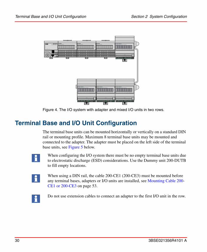
Figure 4. The I/O system with adapter and mixed I/O units in two rows.
Terminal Base and I/O Unit ConfigurationThe terminal base units can be mounted horizontally or vertically on a standard DIN rail or mounting profile. Maximum 8 terminal base units may be mounted and connected to the adapter. The adapter must be placed on the left side of the terminal base units, see Figure 5 below.
When configuring the I/O system there must be no empty terminal base units due to electrostatic discharge (ESD) considerations. Use the Dummy unit 200-DUTB to fill empty locations.
When using a DIN rail, the cable 200-CE1 (200-CE3) must be mounted before any terminal bases, adapters or I/O units are installed, see Mounting Cable 200-CE1 or 200-CE3 on page 53.
Do not use extension cables to connect an adapter to the first I/O unit in the row.
200-IB16Digital Input 16x24 VDC
0 1 2 3 4 5 6 7 8 9 10 11 12 13 14 15
200-IB16Digital Input 16x24 VDC
0 1 2 3 4 5 6 7 8 9 10 11 12 13 14 15
200-IB16Digital Input 16x24 VDC
0 1 2 3 4 5 6 7 8 9 10 11 12 13 14 15
200-ACNControlNet Adapter
Comm OK

Section 2 System Configuration Connecting the Power Supply Cables
3BSE021356R4101 A 31
Connecting the Power Supply CablesConnect a 24 V DC power supply to the I/O units requiring 24 V DC. Digital and analog I/O units should always be separated by a power-line filter, see Section 3, General Installation Instructions on page 35.
Separate wires can be used for each I/O unit or the wires can be chained if the total current for all I/O units does not exceed the maximum current for the cables or screw terminals. See figure.
Figure 5. Chained and individual power supply.
Comm OK
200-IB16Digital Input 16x24 VDC
0 1 2 3 4 5 6 7 8 9 10 11 12 13 14 15
200-IB16Digital Input 16x24 VDC
0 1 2 3 4 5 6 7 8 9 10 11 12 13 14 15
200-IB16Digital Input 16x24 VDC
0 1 2 3 4 5 6 7 8 9 10 11 12 13 14 15
200-ACNControlNet Adapter
Comm OK
200-IB16Digital Input 16x24 VDC
0 1 2 3 4 5 6 7 8 9 10 11 12 13 14 15
200-IB16Digital Input 16x24 VDC
0 1 2 3 4 5 6 7 8 9 10 11 12 13 14 15
200-IB16Digital Input 16x24 VDC
0 1 2 3 4 5 6 7 8 9 10 11 12 13 14 15
200-ACNControlNet Adapter
200-TBN 200-TB2 200-TB3
Powersupply
If the total load current is less than 10 A,
Powersupply
the cables may be chained together as shown.
Adapter
When the total load current is greater than 10 A, the units must be powered by wiring each unit individually to the power supply.

Using 200-PS1.3 to Supply the Remote I/O System Section 2 System Configuration
32 3BSE021356R4101 A
Using 200-PS1.3 to Supply the Remote I/O System
If 200-PS1.3 is used to supply the remote I/O system the following applies.
Connecting the power supply cables
Figure 6. Example of using a 200-PS1.3 Power supply to power 3 adapters in a remote I/O system.
200-ACNControlNet Adapter
Comm OK
200-PS1Power Supply
Power
200-IB16Digital Input 16x24 VDC
0 1 2 3 4 5 6 7 8 9 10 11 12 13 14 15
200-IB16Digital Input 16x24 VDC
0 1 2 3 4 5 6 7 8 9 10 11 12 13 14 15
200-IB16Digital Input 16x24 VDC
0 1 2 3 4 5 6 7 8 9 10 11 12 13 14 15
200-IB16Digital Input 16x24 VDC
0 1 2 3 4 5 6 7 8 9 10 11 12 13 14 15
200-IB16Digital Input 16x24 VDC
0 1 2 3 4 5 6 7 8 9 10 11 12 13 14 15
200-IB16Digital Input 16x24 VDC
0 1 2 3 4 5 6 7 8 9 10 11 12 13 14 15
Comm OK
Comm OK
200-IA8Analog Input 8 Channel
0 1 2 3 4 5 6 7
200-IA8Analog Input 8 Channel
0 1 2 3 4 5 6 7
200-IA8Analog Input 8 Channel
0 1 2 3 4 5 6 7
200-IA8Analog Input 8 Channel
0 1 2 3 4 5 6 7
200-IA8Analog Input 8 Channel
0 1 2 3 4 5 6 7
200-IA8Analog Input 8 Channel
0 1 2 3 4 5 6 7
200-ACNControlNet Adapter
200-ACNControlNet Adapter
200-ACNControlNet Adapter
Adapter
All DC poweredI/O units
AC
AC
Power supply
24 V DC from separate source
All AC powered I/O units
24 V DC from separate source
Combination AC and DC powered I/O units

Section 2 System Configuration Calculating the 24 V Supply to the I/O System
3BSE021356R4101 A 33
Calculating the 24 V Supply to the I/O SystemTo calculate the total current required from the 24 V I/O supply, both the current required by the I/O units themselves and that required by the inputs/outputs must be considered. For the digital inputs the maximum number of simultaneous on-state inputs powered from the supply must be known. For analog and digital outputs the total simultaneous output current must be known. Refer to Appendix A, Technical Specifications on page 261 for the basic data.
Example
In this example, a maximum of 32 of the 48 digital outputs can be on and the output load is 0.1 A per channel.
Number of I/O units used: 3 200-IB16, 3 200-OB16, 1 200-IE8 and 1 200-OE4Number of adapters used: 1 200-ACN
3 200-IB16 require 3 * 16 inputs * 0.008 A = 0.38 A
3 200-OB16. 32 on-state outputs require 3 * 0.05 + 32 * 0.1 A = 3.35 A
1 200-IE8 requires 1 * 0.06 A = 0.06 A
1 200-OE4 requires 1*0.07 A = 0.07 A
1 200-ACN requires 1*0.4 A = 0.4 A___________________________________________________________________
Total current required from 24 V I/O supply: 4.26 A
This means that the 24 V DC power supply should be able to deliver at least 5 A.
The 200-PS1.3 power supply provides sufficient 24 V DC power to operate up to 4 adapter units. Do not attempt to operate an entire I/O system with this power supply.
See Power Installation on page 36.

Calculating the 24 V Supply to the I/O System Section 2 System Configuration
34 3BSE021356R4101 A

3BSE021356R4101 A 35
Section 3 General Installation Instructions
Mandatory installation instructions in this section are marked with the symbol . Such instructions must be followed to fulfil the requirements of the EMC directive.
Installation PrecautionsA system installed according to the instructions in this document meets the company’s environmental specifications for industrial equipment. These specifications concern electric, climatic and mechanical environment.
Figure 7. A system installed according to the instructions in this document is prepared to meet the ABB Automation environmental specifications for industrial equipment.
General cabinet installation instructions are given in the manual Installation Manual – Cabinet.
M
Climate tests
Electrical environment tests
Mechanical tests

Power Installation Section 3 General Installation Instructions
36 3BSE021356R4101 A
By taking the proper precautions, control systems can operate safely and reliably in normal industrial environments. Avoid locating equipment
• where the ambient temperature is outside the range specified in the Technical Specifications
• where the relative humidity exceeds the range specified in the Technical Specifications
• where condensation may occur following sudden temperature changes
• where it may be exposed to high electric or magnetic fields
• where it may be exposed to corrosive or inflammable gases
• where it may be exposed to dust, conductive particles, oil mist or organic solutions
• where it may be exposed to direct sunlight
• where it may be exposed to vibration or mechanical shock
• where it may be exposed to water
• close to powerful high-frequency sources. Possible problems may be solved by means of external filters.
Do not use communication radios and cellular phones within one meter of the control system, as there is a risk that industrial interference levels may be exceeded, which may disturb the system.
Power Installation
Overvoltage Protection
Cables running outdoors may require overvoltage protection, see Devices for Extended Noise Suppression on page 334. Be sure to use the correct device for each cable, otherwise the protection device may not work properly.
Contactors
Avoid mounting contactors and other disturbing equipment in the same cabinet as the control system. If this should be necessary, suppress interference (by snubbers,
M

Section 3 General Installation Instructions Power Installation
3BSE021356R4101 A 37
tranzorbs, diodes, varistors, etc.) and maintain the greatest possible distance between the system and the contactors.
Building and Power Distribution
• The building in which the control system is located must be sufficiently protected against lightning, taking the local conditions into consideration.
• The power distribution network must be sufficiently protected against overvoltage, taking the local conditions into consideration. In severe cases, we recommend gas discharge tubes in the main panel and varistors in the subpanel.
• If the overvoltage protectors do not have a built-in inductance, the cable between the main panel and the subpanel must be longer than 10 meters.
• The building should have a grounding busbar system to minimize common-mode currents. Alternatively, ground current loops must be broken by grounding shielded cables at only one end, or by using isolation amplifiers, fiber modems, etc.
Power Supply
For controllers and I/O systems, supplied by 24 V DC power supply units, see Power Supplies on page 339.
The output from the power supply must be isolated from mains.
It is recommended that the power supply be mounted in the same cabinet as the supplied system. If the power supply does not have a mains fuse, this can be installed between the power-line filter and the 24 V DC power supply.
The controller and the I/O system should, if possible, have separate 24 V DC supplies. If separate supplies are not used, the common 24 V DC power supply should have a separate filter for the controller. If possible, use a separate power supply for analog units to ensure accuracy.
For UL approval of the entire installation the power supply must be UL approved as a “general purpose” power supply.
M

Power Installation Section 3 General Installation Instructions
38 3BSE021356R4101 A
External Power, Communication and I/O Cables
If external power cables, for example 230 V AC or 24 V DC, and signal/communication/I/O cables run in parallel they should be separated by at least 30 cm. The distance between them may be 10 cm for a maximum length of 1 meter. See Recommended Cable Types on page 42.
Filtering
Filtering must be performed according to the figures below. Filters are here divided in type A and type B as follows:
Type A: Corresponds to a two-stage filter for mounting plate assembly.
Type B: Corresponds to a one-stage filter for mounting plate assembly or DIN rail assembly.
A filter of type A is required to protect the mains from emission from the control system and to protect controllers, fieldbus adapters and analog I/O units from noise from the mains. A filter of type B is used to protect controllers, fieldbus adapters and analog I/O units from disturbances from digital I/Os, since the 24 V DC process voltage for digital I/O can pick up noise from the plant. See Power-Line Filters on page 333 for recommended filters of types A and B.
Both types attenuate superimposed high-frequency noise, but they are not overvoltage protectors and do not prevent the voltage from exceeding a certain level. Note also that it is possible to use a filter of type A in place of a type B filter.

Section 3 General Installation Instructions Power Installation
3BSE021356R4101 A 39
Figure 8. Filtering for a controller and I/O system mounted in the same cabinet, without a fieldbus connection. Digital and analog I/O units have separate serial buses which are supplied with power by the controller.
Figure 9. Filtering for a controller and I/O system mounted in the same cabinet, without a fieldbus connection. Digital and analog I/O units are combined on a common serial bus which is supplied with power by the controller.
Controller
230 V AC
Digital I/O
24 V DC
Analog I/O and pulse counter I/O
•
•FilterType A
FilterType B
24 V DC
24 V DC
Controller
230 V AC
Digital I/O
•
•
Analog I/O and pulse counter I/O
FilterType A
FilterType B
FilterType B
Power Installation Section 3 General Installation Instructions
40 3BSE021356R4101 A
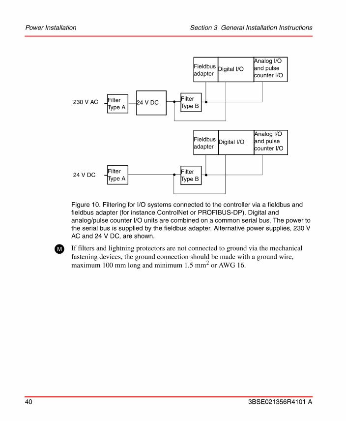
Figure 10. Filtering for I/O systems connected to the controller via a fieldbus and fieldbus adapter (for instance ControlNet or PROFIBUS-DP). Digital and analog/pulse counter I/O units are combined on a common serial bus. The power to the serial bus is supplied by the fieldbus adapter. Alternative power supplies, 230 V AC and 24 V DC, are shown.
If filters and lightning protectors are not connected to ground via the mechanical fastening devices, the ground connection should be made with a ground wire, maximum 100 mm long and minimum 1.5 mm2 or AWG 16.
24 V DC230 V AC
Digital I/O
••FilterType A
FilterType B
Fieldbus adapter
Analog I/Oand pulse counter I/O
24 V DC
Digital I/O
••FilterType A
FilterType B
Fieldbus adapter
Analog I/Oand pulse counter I/O
M

Section 3 General Installation Instructions Installation of Power-Line Filter for 24 V DC
3BSE021356R4101 A 41
Installation of Power-Line Filter for 24 V DC
Figure 11. Both ground connections of the power-line filter must be connected to ground.
For recommended types of filters and overvoltage protectors, see Power-Line Filters on page 333.
Note the following when installing the power-line filter for 24 V DC. If the filter has two ground connections, both must be connected to ground via a ground terminal block, close to the power-line filter, see figure below.

Installation of External Cables Section 3 General Installation Instructions
42 3BSE021356R4101 A
Installation of External Cables
Recommended Cable Types
ABB Automation recommends the cable types specified in Cables for Process Signals on page 340.
Cables can be divided into the following classes:
In order for signals not to interfere with each other, the following minimum distances should be maintained between long, parallel cables outside cabinets.
II–III 0.3 metersI–II 0.3 metersI–III 1.0 meter
Connecting Power Supply Cables
• Always use shielded cables for incoming mains power inside the cabinet unless the power-line filter is mounted directly where the power cable enters the cabinet.
• Connect the mains via a power-line filter to the 24 V supplies.
• Connect the 24 V DC power supply to the I/O units requiring 24 V DC.Digital and analog I/O units should always be separated by a power-line filter. Separate wires can be used for each I/O unit, or the wires can be chained if the total current for all I/O units does not exceed the maximum current for the cables or screw terminals.
For power connection and filtering see also External Power, Communication and I/O Cables on page 38.
Class Description Example
III Non-sensitive signals (noisy)
230 V AC mains
II Moderately sensitive signals (quiet)
24 V DC, digital I/O signals, RS485, PROFIBUS-DP, ControlNet and SattBus
I Sensitive signals (very quiet)
Analog signals, RS232 and Ethernet (trunk cable and AUI cable)
M

Section 3 General Installation Instructions Connecting Cables to Screw Terminals
3BSE021356R4101 A 43
Connecting Cables to Screw Terminals
The wire areas for screw terminals are specified in the appendices Technical Specifications and Recommended Components.
A maximum of 2 wires is allowed in each terminal. However, three wires are allowed if ferrules are used. The wires should be crimped, not soldered.
Recommendations: Tightening torque for the screw terminals: 0.5–0.8 Nm. Use copper wires only, which are UL approved for 60/75 ºC.
Figure 12. Two wires are allowed in each terminal, unless ferrules are used.
Unshielded Cables
Unshielded cables can be used in normal industrial environments for digital I/O signals.
Shielded Cables
Shielded cables must be used for analog I/O and communication (except SattBus and Ethernet twisted pair).
The shields must be clamped to ground (normally the mounting plate) using one of the following alternatives.
M

Connecting Cables to Screw Terminals Section 3 General Installation Instructions
44 3BSE021356R4101 A
Figure 13. Different alternatives of clamping shields to ground.
Alternative 1: Grounding device 200-GDSMount a DIN rail where the cables enter the cabinet, snap a sufficient number of 200-GDS devices onto the DIN rail, remove 10 mm of the sheath and fasten the cables. 200-GDS is designed for cable diameters of 5–8 mm. Let the shield continue as close as possible to the inner conductor connection point.
Alternative 2: Earth rail with grounding clampSee Grounding Devices on page 334 for a recommended grounding clamp to be mounted on an earth rail where the cables enter the cabinet. The distance between the holders must not exceed 100 mm. Use metal holders only.
Alternative 3: Grounding clamp holder 200C-GCHThe clamp holder is screwed onto the back of AC 800C and S200L I/O units. Mount a suitable grounding clamp on the holder (see Grounding Devices on page 334) and tighten it around the exposed braided shield of the cable.
See section Cables for Process Signals on page 340 for recommended cable types.
Alternative 3Alternative 2Alternative 1
200-GDS
Grounding clamp
Earth rail
200C-GCHGrounding clamp

3BSE021356R4101 A 45
Section 4 Mounting Instructions
This section describes how to mount the I/O units and their accessories. The corresponding information regarding 200L I/O units can be found in the manual S200L I/O Hardware and Installation. Refer to Appendix C, Mounting Dimensions on page 341 for scaled drawings and recommended distances between components on a mounting plate. The mounting of I/O units together with controllers is described in the corresponding controller manuals.
Rails and Profiles
I/O units are mounted on either DIN rails or mounting profiles. DIN rails should be chromium plated, for instance yellow chromium treated. Use star washers with every screw used to fasten the DIN rail to the mounting plate. The minimum screw diameter is 5 mm. Recommended DIN rails are specified at DIN rail on page 338.
Mounting profiles incorporate cable ducts. They can be delivered by ABB Automation in different lengths.
DIN rails and mounting profiles used in a central I/O system must be mounted on the same metal mounting plate.
M

Mounting the Terminal Bases Section 4 Mounting Instructions
46 3BSE021356R4101 A
Mounting the Terminal BasesThe terminal base units can be mounted horizontally or vertically on a standard DIN rail or mounting profile. The terminal base should easily snap onto the DIN rail or mounting profile by hand.
Mount the terminal base unit as follows:
1. Remove the cover plug (if used) from the male connector of the unit to which this terminal base unit is to be connected. The cover plug is located on the right side of the terminal base unit.
2. If an adjacent terminal base unit is installed, push the female I/O bus (B) connector to its rightmost position in order not to damage the connector. Also insert the hook (A) on the unit into the slot on the terminal base unit (or adapter) positioned to the left of the terminal base unit. Position the terminal base unit on the DIN rail.
Figure 14. Mounting the terminal base unit.
Use the cover plug to protect the unprotected bus contact.
A
B
C
D

Section 4 Mounting Instructions Mounting the Terminal Bases
3BSE021356R4101 A 47
3. Rotate the terminal base unit onto the DIN rail (C) to hook under the lip on the rear end of the unit.
4. Press the unit down onto the DIN rail until flush. The locking tab (D) will snap into position and lock the unit to the DIN rail.
5. If the terminal base unit does not lock in place, use a screwdriver or similar device to move the locking tab down while pressing the unit flush onto the DIN rail and release the locking tab to lock the unit in place.
6. Push the I/O bus connectors gently into the adjacent adapter (e.g. 200-ANN or 200-ACN) and/or an adjacent teminal base unit (if any).
When configuring the central I/O system there must be no empty terminal base units due to Electrostatic Discharge (ESD) considerations.
Make sure that the connector pins and sockets are in line when the units are plugged together, otherwise there is a risk of damaging the pins. Do not use excessive force.
If the connector (B) is not fully extended (to the left), no I/O unit can be installed. Be careful not to bend the connector pins.

Removing a Terminal Base Unit Section 4 Mounting Instructions
48 3BSE021356R4101 A
Removing a Terminal Base Unit
To remove a terminal base unit proceed as follows:
1. If any I/O unit is fastened to the actual terminal base, remove it.
2. Gently push the bus connector (B) to its rightmost position.
3. If there is an adjacent terminal base on the right hand side, first remove the I/O units mounted on this terminal base and push that terminal base’s bus connector (B) to its rightmost position.
4. Gently use a screwdriver to loosen the locking tab (C) and remove the terminal base from the DIN rail. Note the hook (A).
Figure 15. Removing the terminal base unit.
A
B
C

Section 4 Mounting Instructions Mounting the Adapters
3BSE021356R4101 A 49
Mounting the Adapters
Figure 16. Mounting the adapter. Notice that only adapter 200-ANN is drawn in this figure.
Mount the adapter as follows:
1. Remove the I/O unit (if any) on the adjacent terminal base unit and push the female I/O bus connector (A) to its rightmost position.
2. Position the adapter (B) on the DIN rail (C).
3. Rotate the adapter onto the DIN rail to hook under the lip on the rear side of the adapter.
0 1928
3746
A
D
F
B
C
E
Checking the Basic (Internal) Mountings Section 4 Mounting Instructions
50 3BSE021356R4101 A
4. Press the adapter unit down onto the DIN rail until flush against the DIN rail. Locking tab (E) will snap into position and lock the adapter unit to the DIN rail.
5. If the adapter unit does not lock in place, use a screwdriver or similar device to move the locking tab down while pressing the adapter unit flush onto the DIN rail and release the locking tab to lock the adapter unit in place.
6. Push the female I/O bus connector on the terminal base unit gently into the male equivalent on the adapter and connect the adequate cables to the adapter.
Removing an adapter unit
To remove an adapter proceed as follows:
1. First remove any adjacent I/O unit.
2. Gently push the bus connector (A) to its rightmost position.
3. Remove cables (D and F) or BNC connector if 200-ACN.
4. Pull the locking tab (E) on the adapter downwards and tip the adapter slightly outwards to remove the adapter from the DIN rail.
Checking the Basic (Internal) MountingsAfter the DIN rails and the terminal base units have been mounted, check that the units are hooked into each other and that no metallic particles or other drilling waste has dropped into the backplanes.
Before inserting any I/O unit, check that the terminal base units and adapters are secured on the DIN rail and that the I/O bus connectors are at their leftmost positions.
Also check that connections between the controller and the I/O system are properly made and that the bus terminators are installed correctly.
Be sure to push the serial bus connector all the way in to the left. Otherwise it may cause problems when inserting an I/O unit into the terminal base unit.
Removing an adapter means that you also disconnect the I/O units that are connected to the adapter from the controller.
Section 4 Mounting Instructions Setting the Terminal Base Code Keys
3BSE021356R4101 A 51
Setting the Terminal Base Code Keys
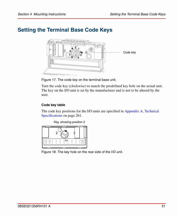
Figure 17. The code key on the terminal base unit.
Turn the code key (clockwise) to match the predefined key hole on the actual unit. The key on the I/O unit is set by the manufacturer and is not to be altered by the user.
Code key table
The code key positions for the I/O units are specified in Appendix A, Technical Specifications on page 261.
Figure 18. The key hole on the rear side of the I/O unit.
Code key
0
6
7
8
9
4
3
2
1
Key, showing position 2

Mounting the I/O Units Section 4 Mounting Instructions
52 3BSE021356R4101 A
Mounting the I/O UnitsTo be able to install an I/O unit on the leftmost terminal base on the lower row, push the bus connector (B) to its leftmost position. Then push the I/O unit into its socket until locked by locking tab (G).
Figure 19. Inserting the I/O unit.
There is a 96-pin connector which interfaces the unit to the terminal base unit. Proceed as below when fastening the units to the terminal base unit.
0
6
7
8
9
4
3
2
1
Rear side of the I/O unitD
B
AG
F
E
C

Section 4 Mounting Instructions Mounting Cable 200-CE1 or 200-CE3
3BSE021356R4101 A 53
1. Rotate the keyswitch, (A) on the terminal base unit (if not already done), clockwise to the position required for the actual unit.
2. Make certain that the bus connector (B) is pushed all the way to the left to connect with the adjacent terminal base/adapter. Note that you cannot properly install the unit unless the connector is fully extended.
3. Position the unit (C) with its guide rail (D) within the groove (F) on the terminal base unit.
4. Press firmly and evenly to seat the unit in the terminal base unit. The unit is seated when the latching mechanism (G) is locked.
5. Be careful not to bend the connector pins (E) on the rear of the I/O unit. Note that some pins on the rear of the I/O unit are shorter than others.
Removing an I/O unit
Release the snap locks (G) and gently pull the I/O unit straight out along the groove (F). Be careful not to wrench the I/O unit so that the connector pins on the rear side (E) of the I/O unit are bent.
Mounting Cable 200-CE1 or 200-CE3
Mounting Cables when DIN Rails are Used
The cable 200-CE1 (200-CE3) must be mounted before any terminal bases, adapters or I/O units are installed. This is because some drilling is required to attach the screws that come with the cable. Refer to Appendix C, Mounting Dimensions on page 341.

Mounting Cables when DIN Rails are Used Section 4 Mounting Instructions
54 3BSE021356R4101 A
Figure 20. Mounting of the cable 200-CE1 (CE-3).
Mount a terminal base temporarily as a template to mark the positions of the cable fixing holes. Make sure you remove the I/O unit before drilling, as metallic particles may otherwise fall into the electronics causing damage or short-circuit. Mounting of terminal bases must thus commence from the right hand side of the DIN rail. If mounting is not carried out in this way, the cable connectors may not be positioned correctly to allow mating to the rightmost terminal base.
Proceed as follows:
1. Insert the cable connector (A) into the mating connector on the right side of the terminal base unit. Push in firmly.
2. Mount the terminal base unit onto the DIN rail1.
3. Use a bradawl or other pointed tool to mark the position of the hole on the mounting plate.
4. Remove the temporarily mounted terminal base with the connected cable.
1. For details on mounting a terminal base unit, see Mounting the Terminal Bases on page 46.
A
B

Section 4 Mounting Instructions Mounting Cables when Mounting Profiles are Used
3BSE021356R4101 A 55
5. Using the mark made in step 3, drill a hole with a diameter of 3.2 mm for the 6-32 screw1 (B) supplied with your kit.
6. Repeat steps 1 to 5 for the row below.
7. After drilling, reinstall both terminal base units and secure with the 6-32 screw (B).
Mounting Cables when Mounting Profiles are Used
Proceed as follows:
1. The mounting profile has a groove (A) into which a locking plate (B) is inserted.
2. Insert the locking plate into the groove.
3. Attach the CE1 (or CE3) cable to the locking plate by fastening the screw in the left hole on the locking plate.
4. Push the CE1 (or CE3) cable into the terminal base.
5. Lock the cable by fastening the screw in the the right hole of the locking plate.
1. This screw has a diameter of 3.7 mm and a length of 27.5 mm. The screw is self-tapping. 6-32 is a screw of type 6, which means a tap diameter of 9/62 inches, i.e. 3.7 mm. A drill-hole of 3.2 mm assumes that the material to be drilled is made from steel with a thickness of 3 mm.
Warning. No drilling may take place when units are mounted on the DIN rail.
Figure21.
Figure21.

Mounting Cables when Mounting Profiles are Used Section 4 Mounting Instructions
56 3BSE021356R4101 A

3BSE021356R4101 A 57
Section 5 Functional Description
This section describes the function of the terminal base units, I/O units and accessories. Remember to check that your controller software allows you to use the functions described.
Terminal Base Unit OverviewThe following table shows which terminal base unit meet various application needs.
Terminal base unit
Purpose
200-TB2 Primarily intended for use with input units when using 2-wire inputs/outputs.
200-TB3 Primarily intended for use with input units when using 3-wire input proximity switches – can also be used with output units.
200-TB3S A spring clamp version of the cage clamp 200-TB3 above – provides faster, simpler wire installation.
200-TB32 Required with the 200-IB32, 200-OB32P and 200-IB16xOB16P units.
200-TB3T Required with the 200-IT8 unit – also provides chassis ground connections for the 200-IR8 and analog units.
200-TBN Provides screw terminals to accept larger gauge wires plus cover for I/O wiring.
200-TBNF Provides 8 5x20 mm fuses, screw terminals, plus a cover for I/O wiring – shipped with fuses for the 200-OA8 and 200-OM8 units, can be used for the 200-OW8 unit (see 200-OW8 installation instructions).

Terminal Base Compatibility Cross Reference Section 5 Functional Description
58 3BSE021356R4101 A
Terminal Base Compatibility Cross Reference
The following table lists the recommended terminal base unit(s) for each I/O unit.
I/O unit Order codePreferred terminal base
Compatible terminal base(s)
AC
230 V AC 200-IM8 200-TBN -
200-OM8 200-TBNF 200-TBN
120 V AC 200-IA8 200-TBN 200-TB3200-TB3S
200-OA8 200-TBNF 200-TB3200-TB3S 200-TBN
DC
24 V DC 200-IB16 200-TB3 200-TB2200-TB3S
200-OB16200-OB16P
200-TB2 200-TB3200-TB3S
200-IB10xOB6 200-TB3 200-TB3S
200-IB32200-OB32P200-IB16xOB16P
200-TB32
200-OB8EP 200-TB2 200-TB3200-TBN200-TBNF
Relay
Relay unit 200-OW8 200-TBNF 200-TB3 200-TB3S 200-TBN

Section 5 Functional Description Terminal Base Compatibility Cross Reference
3BSE021356R4101 A 59
Counters
24 V DC 200-IP2 200-TB3 200-TB3S200-TB2
200-IP4 200-TB3 200-TB3S200-TB2
Analog
24 V DC 200-IE8 200-TB3 200-TB3S
200-OE4 200-TB3 200-TB3S 200-TBN200-TBNF
200-IE4xOE2 200-TB3 200-TB3S
Isolated analog
24 V DC 200-IF4I 200-TB3 200-TB3S 200-TB3T200-TBN
200-OF4I 200-TB3 200-TB3S 200-TB3T200-TBN
Speciality
RTD Input unit 200-IR8 200-TB3 200-TB3S200-TB3T
200-IR8R 200-TB3T 200-TB3T
Thermocouple/mV Input unit
200-IT8 200-TB3T(1)
(1) You can use a 200-TB3 for mV inputs only
I/O unit Order codePreferred terminal base
Compatible terminal base(s)

Terminal Base Unit 200-TB2 Section 5 Functional Description
60 3BSE021356R4101 A
Terminal Base Unit 200-TB2This terminal base unit is intended for connecting an I/O unit and a number of two wire devices to the I/O system.
Figure 22. Terminal base unit 200-TB2
Component identification
1 Hook
2 Female I/O bus connector
3 Screw holes for panel mounting (Ø 4.5 mm), not used
4 Screw terminals for input/output connections
5 Screw terminals for input/output commons (0V DC)
6 Screw terminals for power connections (+24 V DC)
7 Locking tab for DIN rail mounting
8 Groove where the I/O unit guide rail fits
9 Male I/O bus connector
10 Slot for connection of an adjacent terminal base unit
1
23
4
5
6
7
8
9
101112

Section 5 Functional Description Functional Description
3BSE021356R4101 A 61
Functional Description
The terminal base unit transfers data between the I/O units and the controller via an adapter and the serial bus.
A key switch is provided to prevent insertion of incorrect I/O units into a preconfigured terminal base unit. See also Setting the Terminal Base Code Keys on page 51.
This unit assumes that the input devices to be connected are equipped with their own power supply unit.
Screw terminals
Terminal base unit 200-TB2, is equipped with three screw terminal rows.
Figure 23. Screw terminal rows for 200-TB2.
The upper row has 16 terminals (0–15) for input/output signals.
The middle row consists of eighteen 0 V DC screw terminals (16–33) which are internally connected. The rightmost and leftmost screw terminals are for connection to power supply.
The lower row consists of two +24 V DC screw terminals (34, 51) which are internally connected. These terminals are for connection to power supply.
See also section Connecting Power Supply Cables on page 42.
11 Code key – set to the position required for the installed I/O unit
12 Snap lock
Upper row: 0–15
Middle row: 16–33
Lower row: 34, 51

Functional Description Section 5 Functional Description
62 3BSE021356R4101 A
Figure 24. The 200-TB2 functional block diagram.
Input/Output16
18
2
0 V DC or AC
24 V DC or 120 V ACI/O
uni
t int
erfa
ce
Ser
ial b
us

Section 5 Functional Description Terminal Base Unit 200-TB3
3BSE021356R4101 A 63
Terminal Base Unit 200-TB3This terminal base unit is intended for connecting an I/O unit and a number of two or three wire devices to the I/O system.
Figure 25. Terminal base unit 200-TB3
Component identification
1 Hook
2 Female I/O bus connector
3 Screw holes for panel mounting (Ø 4.5 mm), not used
4 Screw terminals for input/output connections
5 Screw terminals for input/output commons (0V DC)
6 Screw terminals for power connections (+24 V DC)
7 Locking tab for DIN rail mounting
1
2
3
4
5
6
7
8
9
101112

Functional Description Section 5 Functional Description
64 3BSE021356R4101 A
Functional Description
The terminal base unit transfers data between the I/O units and the controller via an adapter and the serial bus.
A key switch is provided to prevent insertion of incorrect I/O units into a preconfigured terminal base unit. See also Setting the Terminal Base Code Keys on page 51.
Screw terminals
Terminal base unit 200-TB3, is equipped with three screw terminal rows.
Figure 26. Screw terminals for 200-TB3.
The upper row has 16 terminals (0–15) for input/output signals.
The middle row consists of eighteen 0 V DC screw terminals (16–33) which are internally connected. The rightmost and leftmost screw terminals are for connection to power supply.
The lower row consists of eighteen +24 V DC screw terminals (34–51) which are internally connected. The leftmost and rightmost terminals are for connection to power supply.
See also Connecting Power Supply Cables on page 42.
8 Groove where the I/O unit guide rail fits
9 Male I/O bus connector
10 Slot for connection of an adjacent Terminal base unit
11 Code key – set to the position required for the installed I/O unit
12 Snap lock
Upper row: 0–15
Middle row: 16–33
Lower row: 34–51

Section 5 Functional Description Functional Description
3BSE021356R4101 A 65
Figure 27. The 200-TB3 functional block diagram.
Input/Output16
18
18
0 V DC or AC
24 V DC or 120 V ACI/O
uni
t int
erfa
ce
Ser
ial b
us

Terminal Base Unit 200-TB3S Section 5 Functional Description
66 3BSE021356R4101 A
Terminal Base Unit 200-TB3SThis terminal base unit is intended for connecting an I/O unit and a number of two or three wire devices to the I/O system.
Note that the 200-TB3S is a spring clamp version of 200-TB3. All connections on 200-TB3S are spring clamps. Always use a screw driver when inserting the cable.
Figure 28. Terminal base unit 200-TB3S.
Component identification
1 Hook
2 Female I/O bus connector
3 Screw holes for panel mounting (Ø 4.5 mm), not used
4 Cage clamps for input/output connections
5 Cage clamps for input/output commons (0 V DC)
1
2
3
4
5
6
7
8
9
10
1112

Section 5 Functional Description Functional Description
3BSE021356R4101 A 67
Functional Description
The terminal base unit transfers data between the I/O units and the controller via an adapter and the serial bus.
A key switch is provided to prevent insertion of incorrect I/O units into a preconfigured terminal base unit. See also Setting the Terminal Base Code Keys on page 51.
Spring clamp terminals
Terminal base unit 200-TB3S, is equipped with three rows of spring clamp terminals.
Figure 29. Spring clamp terminals for 200-TB3S.
The upper row has sixteen terminals (0–15) for input/output signals.
The middle row consists of eighteen 0 V DC spring clamp terminals (16–33) which are internally connected. The rightmost and leftmost screw terminals are for connection to a power supply.
The lower row consists of eighteen +24 V DC spring clamp terminals (34–51) which are internally connected. The leftmost and rightmost terminals are for connection to a power supply.
6 Cage clamps for power connections (+ 24 V DC)
7 Locking tab for DIN rail mounting
8 Groove where the I/O unit guide rail fits
9 Male I/O bus connector
10 Slot for connection of an adjacent Terminal base unit
11 Code key – set to the position required for the installed I/O unit
12 Snap lock
Upper row: 0–15
Middle row: 16–33
Lower row: 34–51
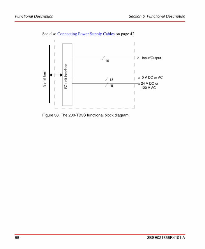
Functional Description Section 5 Functional Description
68 3BSE021356R4101 A
See also Connecting Power Supply Cables on page 42.
Figure 30. The 200-TB3S functional block diagram.
Input/Output16
18
18
0 V DC or AC
24 V DC or 120 V ACI/O
uni
t int
erfa
ce
Ser
ial b
us

Section 5 Functional Description Terminal Base Unit 200-TB32
3BSE021356R4101 A 69
Terminal Base Unit 200-TB32This terminal base unit is intended for connecting an I/O unit and a number of two- or three-wire devices to the I/O system. It is required for I/O units 200-IB32, 200-OB32P, and IB16xOB16P.
Figure 31. Terminal base unit 200-TB32.
Component identification
1 Hook
2 Female I/O bus connector
3 Screw holes for panel mounting (Ø 4.5 mm), not used
4 Screw terminals for input/output connections
5 Screw terminals for input/output connections
6 Screw terminals for power and signal ground connections (+24 V DC and 0 V DC)
1
2
3
4
5
6
7
8
9
101112
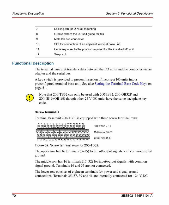
Functional Description Section 5 Functional Description
70 3BSE021356R4101 A
Functional Description
The terminal base unit transfers data between the I/O units and the controller via an adapter and the serial bus.
A key switch is provided to prevent insertion of incorrect I/O units into a preconfigured terminal base unit. See also Setting the Terminal Base Code Keys on page 51.
Screw terminals
Terminal base unit 200-TB32 is equipped with three screw terminal rows.
Figure 32. Screw terminal rows for 200-TB32.
The upper row has 16 terminals (0–15) for input/output signals with common signal ground.
The middle row has 16 terminals (17–32) for input/output signals with common signal ground. Terminals 16 and 33 are not connected.
The lower row consists of eighteen terminals for power and signal ground connections. Terminals 35, 37, 39 and 41 are internally connected for +24 V DC
7 Locking tab for DIN rail mounting
8 Groove where the I/O unit guide rail fits
9 Male I/O bus connector
10 Slot for connection of an adjacent terminal base unit
11 Code key – set to the position required for the installed I/O unit
12 Snap lock
Note that 200-TB32 can only be used with 200-IB32, 200-OB32P and 200-IB16xOB16P, though other 24 V DC units have the same backplane key code.
Upper row: 0–15
Middle row: 16–33
Lower row: 34–51

Section 5 Functional Description Functional Description
3BSE021356R4101 A 71
supply to the upper row, and terminals 43, 45, 47 and 49 are used for +24 V DC supply to the middle row. Terminals 36, 38, 40 and 42 are internally connected for common 0 V DC to the upper row, and terminals 44, 46, 48 and 50 provides 0 V DC connection to the middle row. Terminals 34 and 51 are not connected.
See also Connecting Power Supply Cables on page 42.
Figure 33. The 200-TB32 functional block diagram.
Numbers within parentheses in the diagram refer to terminal numbers on the terminal base unit.
Each group of four terminals for 24 V DC and 0 V supply are internally connected in the terminal base unit (for instance, terminals 35, 37, 39, and 41 are internally connected).
16
4
Not connected (16, 33, 34, 51)
I/O u
nit i
nter
face
Ser
ial b
us
Inputs/outputs (17–32)
Inputs/outputs (0–15)
16
424 V DC for upper row (35, 37, 39, 41)
16
24 V DC for middle row (43, 45, 47, 49)
4
0 V DC for upper row (36, 38, 40, 42)
0 V DC for middle row (44, 46, 48, 50)4
4

Terminal Base Unit 200-TB3T Section 5 Functional Description
72 3BSE021356R4101 A
Terminal Base Unit 200-TB3TThis terminal base unit is intended for connecting an I/O unit and a number of 2- and 3-wire devices to the I/O system. This terminal base is mainly intended for use with 200-IT8.
Six screw terminals are intended for cold junction inputs for compensation via an external thermistor. This is a requirement when used with 200-IT8.
Eight screw terminals are intended to provide connection points to chassis ground. This intent is to provide a place to connect the shield wire when using shielded cables of analog units.
Figure 34. Terminal base unit 200-TB3T.
1
2
3
4
5
6
7
8
9
101112

Section 5 Functional Description Functional Description
3BSE021356R4101 A 73
Component identification
Functional Description
The terminal base unit transfers data between the I/O units and the controller via an adapter and the serial bus.
A key-switch is provided to prevent insertion of incorrect I/O units into a preconfigured terminal base unit. See also Setting the Terminal Base Code Keys on page 51.
1 Hook
2 Female I/O bus connector
3 Screw holes for panel mounting (Ø 4.5 mm), not used
4 See description below
5 See description below
6 See description below
7 Locking tab for DIN rail mounting
8 Groove where the I/O unit guide rail fits
9 Male I/O bus connector
10 Slot for connection of an adjacent Terminal base unit
11 Code key – set to the position required for the installed I/O unit
12 Snap lock

Functional Description Section 5 Functional Description
74 3BSE021356R4101 A
Screw terminals
Terminal base unit 200-TB3T, is equipped with three screw terminal rows.
Figure 35. Screw terminals for 200-TB3T.
See also Connecting Power Supply Cables on page 42.
16 I/O terminals
8 separate reserved terminals
8 chassis ground
Cold junction input
24 V DC (for power supply)
24 V DC (for power supply)
Lower row
Middle row
Upper row
10 0 V DC terminals
0 V DC(for power supply)
0 V DC (for power supply)
Cold junction shield returnCold junction input
Cold junction inputCold junction shield Cold junction input

Section 5 Functional Description Functional Description
3BSE021356R4101 A 75
Figure 36. The 200-TB3T functional block diagram.
Input/Output
3-wire RTD
0 V DC or AC
I/O u
nit i
nter
face
Ser
ial b
us
24 V DC or 120 V AC
Cold junction
Chassis ground

Terminal Base Unit 200-TBN Section 5 Functional Description
76 3BSE021356R4101 A
Terminal Base Unit 200-TBNThis terminal base unit is intended for connecting an I/O unit and a number of devices to the I/O system. Screw terminals on 200-TBN are well insulated and can be used for connection of units which allows both +24 V DC and 230 V AC connections.
Figure 37. Terminal base unit 200-TBN.
2
3
4
5
9
1112
8
10
6
1
7
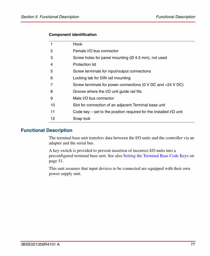
Section 5 Functional Description Functional Description
3BSE021356R4101 A 77
Component identification
Functional Description
The terminal base unit transfers data between the I/O units and the controller via an adapter and the serial bus.
A key switch is provided to prevent insertion of incorrect I/O units into a preconfigured terminal base unit. See also Setting the Terminal Base Code Keys on page 51.
This unit assumes that input devices to be connected are equipped with their own power supply unit.
1 Hook
2 Female I/O bus connector
3 Screw holes for panel mounting (Ø 4.5 mm), not used
4 Protection lid
5 Screw terminals for input/output connections
6 Locking tab for DIN rail mounting
7 Screw terminals for power connections (0 V DC and +24 V DC)
8 Groove where the I/O unit guide rail fits
9 Male I/O bus connector
10 Slot for connection of an adjacent Terminal base unit
11 Code key – set to the position required for the installed I/O unit
12 Snap lock

Functional Description Section 5 Functional Description
78 3BSE021356R4101 A
Screw terminals
Terminal base unit 200-TBN, is equipped with two screw terminal rows.
Figure 38. Screw terminals for 200-TBN.
The upper row has 10 screw terminals, where terminal 16 and 33 are dedicated for 0 V DC and even numbered terminals for input/output signals from a device.
The lower row consists of 10 screw terminals, where 34 and 51 are for +24 V DC connection and odd numbered terminals for input/output signals from a device.
Also see Connecting Power Supply Cables on page 42.
Figure 39. The 200-TBN functional block diagram.
Upper row
Lower row
I/O-u
nit i
nter
face
Ser
ial b
us
Input/output
0 V DC or AC
24 V DC or 230 AC
16
2
2

Section 5 Functional Description Terminal Base Unit 200-TBNF
3BSE021356R4101 A 79
Terminal Base Unit 200-TBNFThis terminal base unit is intended for connecting an I/O unit and a number of devices to the I/O system. Screw terminals on 200-TBNF are well insulated and can be used for connection of units which allows both +24 V DC and 230 V AC connections. 200-TBNF is equipped with holders for eight fuses connected in series with the eight channels on the top row.
Figure 40. Terminal base unit 200-TBNF.
2
3
4
10
1213
9
111
8
3
56 7

Functional Description Section 5 Functional Description
80 3BSE021356R4101 A
Component identification
Functional Description
The terminal base unit transfers data between the I/O units and the controller via an adapter and the serial bus. The upper row has holders for 8 fuses. This unit is primarily for units with 8 inputs or outputs.
A key switch is provided to prevent insertion of incorrect I/O units into a preconfigured terminal base unit. See also Setting the Terminal Base Code Keys on page 51.
It is assumed that input devices to be connected to this unit are equipped with their own power supply unit.
1 Hook
2 Female I/O bus connector
3 Screw holes for panel mounting (Ø 4.5 mm), not used
4 Protection lid
5 Screw terminals for input/output connections
6 Locking tab for DIN rail mounting
7 Screw terminals for power connections (0 V DC and +24 V DC)
8 Fuse holders
9 Groove where the I/O unit guide rail fits
10 Male I/O bus connector
11 Slot for connection of an adjacent Terminal base unit
12 Code key – set to the position required for the installed I/O unit
13 Snap lock
3 A fuses are supplied with the terminal base unit to be used with 200-OW8. Fuses for other units are described in the technical data for the actual I/O unit.

Section 5 Functional Description Functional Description
3BSE021356R4101 A 81
Screw terminals
Terminal base unit 200-TBNF, is equipped with two screw terminal rows.
Figure 41. Screw terminals for 200-TBNF.
The upper row has 10 screw terminals, where terminal 16 and 33 are dedicated for 0 V DC and even numbered terminals for input/output signals from a device. This row is secured by fuses.
The lower row consists of 10 screw terminals, where 34 and 51 are for +24 V DC connection and odd numbered terminals for input/output signals from a device.
Also see Connecting Power Supply Cables on page 42.
Figure 42. The 200-TBNF functional block diagram.
Upper row
Lower row
Input/output
0 V DC or AC
24 V DC or 230 AC
8
2
2
8Input/output
I/O-u
nit i
nter
face
Ser
ial b
us

Digital Input Unit 200-IB16 Section 5 Functional Description
82 3BSE021356R4101 A
Digital Input Unit 200-IB16200-IB16 is an I/O unit for 16 digital input signals. The inputs are filtered and galvanically isolated by optocouplers. The status of each signal is indicated by an LED on the front of the unit. The unit has programmable sample time.
1 = Holder for insertable label for individual input designations2 = Status indicators - show status of individual inputs.
Figure 43. Digital input unit 200-IB16.
Front Panel
Indicators
Functional Description
The inputs are galvanically isolated by optocouplers and the 16 inputs shares a common ground connection. The unit is connected via the terminal base unit.
The status of each input signal is indicated by a yellow LED on the front of the unit. Each signal is isolated from the logic circuits by an optocoupler and filtered by a digital filter.The filter has one common time constant for inputs 0–11 and another
Indication Function
0–15 Yellow LED, lit when inputs are TRUE
2
1

Section 5 Functional Description Functional Description
3BSE021356R4101 A 83
for inputs 12–15. The sum of the hardware and digital filter time constants affects the shortest possible pulse length that can be detected and the highest possible frequency that can be connected to the pulse counter.1
Power for the internal logic is provided via the adapter for the I/O system.
The unit is equipped with a 16-bit2 pulse counter connected to channel 15. The counter is reset when the unit is without power.
Figure 44. The 200-IB16 functional block diagram.
Numbers within parentheses in the diagram refer to signal terminals on the terminal base unit, (e.g. 200-TB3) connected to the I/O unit. Note that screw terminals 17–32 do not exist on 200-TBN and 200-TBNF.
1. Only article No. 490-1760-59 or later. Older versions (article No. 490-1760-43 or 490-1760-05, -26) have the following function: The input signals are sampled at intervals determined by sample time. The signal status is changed only if two consecutive samples are the same. The sample time can be set by the programming software.
2. Only article No. 490-1760-59 or later. Older versions have a 5-bit counter (article No. 490-1760-43) or none (article No. 490-1760-05, -26).
Ser
ial b
us
counter
Opto
coupler
Channel 1
Channel 15
Power + 5 V
Channel 0
Bus
inte
rfac
e
Input 0 (0)
0 V DC (17)
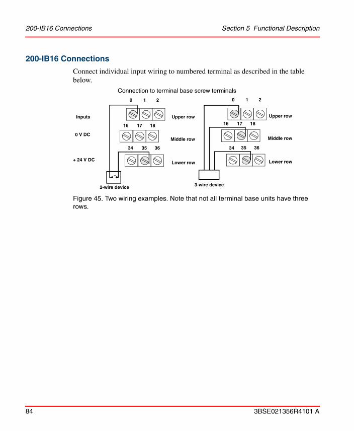
200-IB16 Connections Section 5 Functional Description
84 3BSE021356R4101 A
200-IB16 Connections
Connect individual input wiring to numbered terminal as described in the table below.
Figure 45. Two wiring examples. Note that not all terminal base units have three rows.
Inputs
+ 24 V DC
2-wire device 3-wire device
0 V DC
0 1 2
16 17 18
34 35 36
0 1 2
16 17 18
35 3634
Upper row
Middle row
Lower row
Connection to terminal base screw terminals
Upper row
Middle row
Lower row

Section 5 Functional Description 200-IB16 Connections
3BSE021356R4101 A 85
Screw terminal connections
Input
200-TB2 & 200-TB3200-TBN & 200-TBNF
Terminals to be connected
Signal (upper row)
0 V DC(middle row)
24 V DC(lower row)
Signal
0 0 17 35 0
1 1 18 36 1
2 2 19 37 2
3 3 20 38 3
4 4 21 39 4
5 5 22 40 5
6 6 23 41 6
7 7 24 42 7
8 8 25 43 8
9 9 26 44 9
10 10 45 45 10
11 11 28 46 11
12 12 29 47 12
13 13 30 48 13
14 14 31 49 14
15 15 32 50 15
0 V DC 16–33 16, 33
+24 V DC 34–51 34, 51

Digital Output Unit 200-OB16 Section 5 Functional Description
86 3BSE021356R4101 A
Digital Output Unit 200-OB16200-OB16 is an I/O unit for 16 digital output signals. The outputs are galvanically isolated. The status of each signal is indicated by a LED on the front of the unit.
1 = Holder for insertable label for individual output designations2 = Status indicators – show status of individual outputs.
Figure 46. Digital output unit 200-OB16.
Front Panel
Indicators
Indication Function
0–15 Yellow LED, lit when outputs are TRUE
2
1

Section 5 Functional Description Functional Description
3BSE021356R4101 A 87
Functional Description
The outputs are galvanically isolated by optocouplers and the 16 outputs share a common ground connection. The unit is connected via the terminal base unit.
The status of each output signal is indicated by a yellow LED on the front of the unit. Output indicators do not work if +24 V DC is missing.
Power for the internal logic is provided via the adapter for the I/O system.
Figure 47. The 200-OB16 functional block diagram.
Numbers within parentheses in the diagram refer to signal terminals on the terminal base unit, (e.g. 200-TB3) connected to the I/O unit. Note that screw terminals 35–50 only exist on 200-TB3. Terminals 17–32 do not exist on 200-TBN and 200-TBNF.
Bus
inte
rfac
e
Ser
ial b
us
Opto
coupler
Channel 0
Channel 1
Channel 15
Power + 5 V
+24 V DC (35)
Output 0 (0)
0 V DC (17)
+5 V

200-OB16 Connections Section 5 Functional Description
88 3BSE021356R4101 A
200-OB16 Connections
Connect individual output wiring to numbered terminal as described in the table below. Up to four outputs can be connected in parallel (the total load must, however, never exceed 1.8 A).
Figure 48. Wiring example. Note that not all terminal base units have three rows.
2-wire device
0 1 2
16 17 18
34 35 36
Outputs
+ 24 V DC
0 V DC
Upper row
Middle row
Lower row
Connection to terminal base screw terminals

Section 5 Functional Description 200-OB16 Connections
3BSE021356R4101 A 89
Screw terminal connections
Output
200-TB2 & 200-TB3200-TBN & 200-TBNF
Terminals to be connected
Signal (upper row)
0 V DC(middle row)
24 V DC(lower row)
Signal
0 0 17 35 0
1 1 18 36 1
2 2 19 37 2
3 3 20 38 3
4 4 21 39 4
5 5 22 40 5
6 6 23 41 6
7 7 24 42 7
8 8 25 43 8
9 9 26 44 9
10 10 45 45 10
11 11 28 46 11
12 12 29 47 12
13 13 30 48 13
14 14 31 49 14
15 15 32 50 15
0 V DC 16–33 16, 33
+24 V DC 34–51 34, 51

Digital Output Unit 200-OB16P Section 5 Functional Description
90 3BSE021356R4101 A
Digital Output Unit 200-OB16P200-OB16P is an I/O unit for 16 digital output signals. The outputs are galvanically isolated and short-circuit proof. The status of each signal is indicated by a LED on the front of the unit.
1 = Holder for insertable label for individual output designations2 = Status indicators – LEDs show status of individual outputs.
Figure 49. Digital output unit 200-OB16P.
Front Panel
Indicators
200-OB16P can be used with the version B or later of Adapter 200-ANN.
Indication Function
0–15 Yellow LED, lit when outputs are TRUE
2
1

Section 5 Functional Description Functional Description
3BSE021356R4101 A 91
Functional Description
The outputs are galvanically isolated by optocouplers and the 16 outputs share a common ground connection. The unit is connected via the terminal base unit.
The status of each output signal is indicated by a yellow LED on the front of the unit. The output status indicators do not work if the +24 V DC is missing.
Power for the internal logic is provided via the adapter for the I/O system.
An output shuts down and limits the current to about 200 mA when a short-circuit or an over-current (500 mA) is detected. The output returns to its normal state as soon as the short-circuit is removed and the temperature of the circuit is low enough.
Figure 50. The 200-OB16P functional block diagram.
Numbers within parentheses in the diagram refer to signal terminals on the terminal base unit, (e.g. 200-TB3) connected to the I/O unit. Note that screw terminals 35–50 only exist on 200-TB3. Terminals 17–32 do not exist on 200-TBN and 200-TBNF.
Bus
inte
rfac
e
Ser
ial b
us
Opto
coupler
Channel 0
Channel 1
Channel 15
Power + 5 V
+24 V DC (35)
Output 0 (0)
0 V DC (17)
Protection circuit
+5 V

200-OB16P Connections Section 5 Functional Description
92 3BSE021356R4101 A
200-OB16P Connections
Connect individual output wiring to numbered terminal as described in the table below. Up to four outputs can be connected in parallel.
Figure 51. Wiring example. Note: not all terminal base units have three rows.
2-wire device
0 1 2
16 17 18
34 35 36
Outputs
+ 24 V DC
0 V DC
Upper row
Middle row
Lower row
Connection to terminal base screw terminals

Section 5 Functional Description 200-OB16P Connections
3BSE021356R4101 A 93
Screw terminal connections
Output
200-TB2 & 200-TB3200-TBN & 200-TBNF
Terminals to be connected
Signal (upper row)
0 V DC(middle row)
24 V DC(lower row)
Signal
0 0 17 35 0
1 1 18 36 1
2 2 19 37 2
3 3 20 38 3
4 4 21 39 4
5 5 22 40 5
6 6 23 41 6
7 7 24 42 7
8 8 25 43 8
9 9 26 44 9
10 10 45 45 10
11 11 28 46 11
12 12 29 47 12
13 13 30 48 13
14 14 31 49 14
15 15 32 50 15
0 V DC 16–33 16, 33
+24 V DC 34–51 34, 51

Digital Input/Output Combo Unit 200-IB10xOB6 Section 5 Functional Description
94 3BSE021356R4101 A
Digital Input/Output Combo Unit 200-IB10xOB6200-IB10xOB6 is an I/O unit for 10 digital input and 6 digital output signals. The inputs are filtered and the unit is galvanically isolated. The inputs have programmable filter time. The status of each signal is indicated by a LED on the front of the unit.
1 = Holder for insertable label for individual input designations2 = Status indicators - show status of individual inputs and outputs.
Figure 52. Digital input/output combo unit 200-IB10xOB6.
Front Panel
Indicators
Indication Function
0–15 Yellow LED, lit when inputs/outputs are TRUE
1
2

Section 5 Functional Description Functional Description
3BSE021356R4101 A 95
Functional Description
The 10 digital input and the 6 digital output signals are connected to the unit via the screw terminals on the terminal base unit.
The status of each input/output signal is indicated by a yellow LED on the front of the unit. The inputs and outputs are galvanically isolated by optocouplers and shares a common ground connection. The inputs have a digital filter.
Filter time can be set by the programming software.
The outputs can deliver up to 2 A. Power for the internal logic is provided via the adapter.

Functional Description Section 5 Functional Description
96 3BSE021356R4101 A
Figure 53. The 200-IB10xOB6 functional block diagram.
Numbers within parentheses in the diagram, refer to signal terminals on the terminal base unit (e.g. 200-TB3). Note that screw terminals 35–50 only exist on 200-TB3.
coupler
Opto
coupler
Channel 0
Channel 8
Channel 9
Channel 11
Channel 15
+ 5V
+ 5VPower
Bus
inte
rfac
e
Ser
ial b
usInput 0 (0)
0 V DC (17)
+24 V DC (45)
Output 0 (10)
0 V DC (27)
opto
Channel 10

Section 5 Functional Description 200-IB10xOB6 Connections
3BSE021356R4101 A 97
200-IB10xOB6 Connections
Connect individual input or output wiring to numbered terminal as described in the table below. Up to four outputs can be connected in parallel (the total load must, however, never exceed 1.8 A).
Figure 54. Two wiring examples.
Not all terminal base units have three rows. See also examples in 200-IB16 Connections on page 84 and 200-OB16 Connections on page 88.
2-wire device
0 ........ 11 12
Inputs
+ 24 V DC
0 V DC
Upper row
Middle row
Lower row
Connection to terminal base screw terminals10
16 27 28
34 ........ 46 4745
17
2-wire device
Outputs

200-IB10xOB6 Connections Section 5 Functional Description
98 3BSE021356R4101 A
Screw terminal connections
200-TB2 & 200-TB3200-TBN & 200-TBNF
Terminals to be connected
Signal(upper row)
0 V DC(middle row)
24 V DC(lower row)
Signal
Input 0 0 17 35 0
Input 1 1 18 36 1
Input 2 2 19 37 2
Input 3 3 20 38 3
Input 4 4 21 39 4
Input 5 5 22 40 5
Input 6 6 23 41 6
Input 7 7 24 42 7
Input 8 8 25 43 8
Input 9 9 26 44 9
Output 10 10 27 45 10
Output 11 11 28 46 11
Output 12 12 29 47 12
Output 13 13 30 48 13
Output 14 14 31 49 14
Output 15 15 32 50 15
0 V DC 16–33 16, 33
+24 V DC 34–51 34, 51

Section 5 Functional Description Digital Input Unit 200-IB32
3BSE021356R4101 A 99
Digital Input Unit 200-IB32200-IB32 is an I/O unit for 32 digital input signals. The status of each signal is indicated by a LED on the front of the unit.
1 = Holder for insertable label for individual input designations2 = Status indicators - show status of individual inputs.
Figure 55. Digital input unit 200-IB32.
Front Panel
Indicators
200-OB32P must be used with a 200-TB32 terminal base unit.
If you remove or insert the module while the backplane power is on, an electrical arc can occur. This could cause an explosion in hazardous location installations. Be sure that power is removed or the area is nonhazardous before proceeding.
Indication Function
0–31 Yellow LED, lit when inputs are TRUE
2
1

Functional Description Section 5 Functional Description
100 3BSE021356R4101 A
Functional Description
The inputs are isolated from the logic circuits in two groups by optocouplers. Each of the two input groups share common power and ground connections. The unit is connected via the terminal base unit.
The signals are filtered by a digital filter with a filter time common for all 31 input signals, set with the programming software.
Power for the internal logic is provided via the adapter for the I/O system.
Figure 56. The 200-IB32 functional block diagram.
Numbers within parentheses in the diagram refer to signal terminals on the terminal base unit (i.e. 200-TB32), connected to the I/O unit.
Ser
ial b
us
Opto
coupler
Channel 1
Channel 15
Power + 5 V
Channel 0 or 16Input 0 (0)
0 V DC (36,38,40 and 42)
Input 1 (1)
Input (15)
Channel 0 or 16
Opto
coupler
Channel 17
Channel 31
Input 16 (17)
0 V DC(44, 46, 48 and 50)
Input 31 (32)
Channel 16
Input 17 (18)
Bus
inte
rfac
e

Section 5 Functional Description 200-IB32 Connections
3BSE021356R4101 A 101
200-IB32 Connections
Connect individual input wirings to the numbered terminals as described in the table below.
Figure 57. Two wiring examples.
Screw terminal connections
Input
200-TB32
Terminals to be connected
Signal 0 V DC 24 V DC
0 0 36, 38, 40, 42 35, 37, 39, 41
1 1
2 2
3 3
4 4
5 5
6 6
7 7
8 8
9 9
2-wire device3-wire device
0 1 2
16 17 18
34 35 36
0 1 2
16 17 18
35 3634
Upper row
Middle row
Lower row
Connection to terminal base screw terminals
Upper row
Middle row
Lower row (+24 V & 0 V DC)
(Inputs)
(Inputs)
+24 V DC
0 V
+24 VDC
(Inputs)
(Inputs)
(+24 V & 0 V DC)

200-IB32 Connections Section 5 Functional Description
102 3BSE021356R4101 A
10 10 36, 38, 40, 42 35, 37, 39, 41
11 11
12 12
13 13
14 14
15 15
16 17 44, 46, 48, 50 43, 45, 47, 49
17 18
18 19
19 20
20 21
21 22
22 23
23 24
24 25
25 26
26 27
27 28
28 29
29 30
30 31
31 32
Input
200-TB32
Terminals to be connected
Signal 0 V DC 24 V DC

Section 5 Functional Description Digital Output Unit 200-OB32P
3BSE021356R4101 A 103
Digital Output Unit 200-OB32P200-OB32P is an I/O unit for 32 digital output signals. The status of each signal is indicated by a LED on the front of the unit.
1 = Holder for insertable label for individual output designations2 = Status indicators – LEDs show status of individual outputs.
Figure 58. Digital output unit 200-OB32P.
Indicators
200-OB32P must be used with a 200-TB32 terminal base unit.
If you remove or insert the module while the backplane power is on, an electrical arc can occur. This could cause an explosion in hazardous location installations. Be sure that power is removed or the area is nonhazardous before proceeding.
Indication Function
0–31 Yellow LED, lit when outputs are TRUE
2
1

Functional Description Section 5 Functional Description
104 3BSE021356R4101 A
Functional Description
The outputs are short-circuit proof and are isolated from the logic circuits in two groups by optocouplers. Each of the two output groups share common power and ground connections. The unit is connected via the terminal base unit.
The status of each output signal is indicated by a yellow LED on the front of the unit. The output status indicators do not work if the +24 V DC is missing.
Power for the internal logic is provided via the adapter for the I/O system.
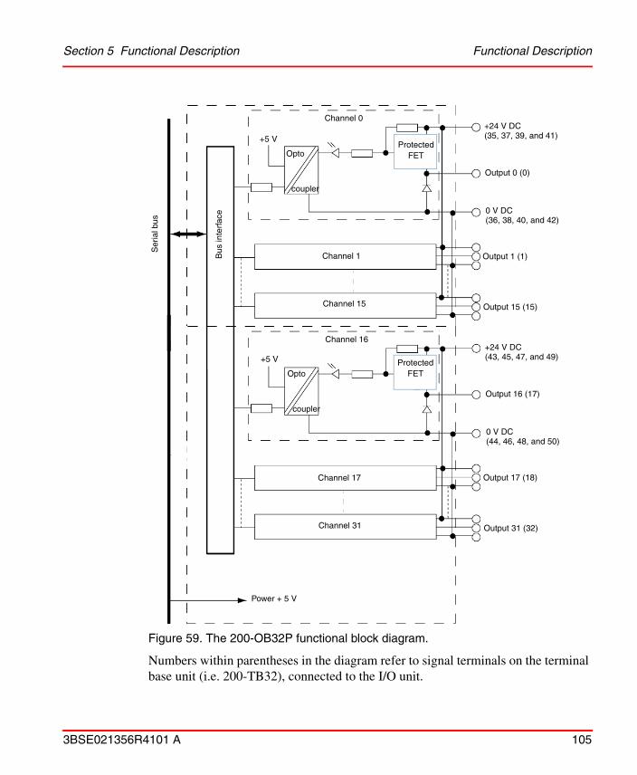
Section 5 Functional Description Functional Description
3BSE021356R4101 A 105
Figure 59. The 200-OB32P functional block diagram.
Numbers within parentheses in the diagram refer to signal terminals on the terminal base unit (i.e. 200-TB32), connected to the I/O unit.
Bus
inte
rfac
e
Ser
ial b
usOpto
coupler
Channel 0
Channel 1
Channel 15
Power + 5 V
+24 V DC (35, 37, 39, and 41)
Output 0 (0)
0 V DC (36, 38, 40, and 42)
+5 V
Output 1 (1)
Output 15 (15)
Protected FET
Protected FET
Channel 16+24 V DC (43, 45, 47, and 49)
Output 16 (17)
0 V DC (44, 46, 48, and 50)
Output 17 (18)
Output 31 (32)
Channel 17
Channel 31
Opto
coupler
+5 V

200-OB32P Connections Section 5 Functional Description
106 3BSE021356R4101 A
200-OB32P Connections
Connect individual output wirings to the numbered terminals as described in the table below.
Figure 60. Wiring example.
Screw terminal connections
Output Signal
200-TB32
Terminals to be connected
Signal 0 V DC 24 V DC
0 0 36, 38, 40, 42 35, 37, 39, 41
1 1
2 2
3 3
4 4
5 5
6 6
7 7
8 8
9 9
2-wire device
0 1 2
16 17 18
34 35 36
Outputs
Upper row (Outputs)
Middle row (Outputs)
Lower row (+24 V & 0 V DC)
Connection to terminal base screw terminals
0 V

Section 5 Functional Description 200-OB32P Connections
3BSE021356R4101 A 107
10 10 36, 38, 40, 42 35, 37, 39, 41
11 11
12 12
13 13
14 14
15 15
16 17 44, 46, 48, 50 43, 45, 47, 49
17 18
18 19
19 20
20 21
21 22
22 23
23 24
24 25
25 26
26 27
27 28
28 29
29 30
30 31
31 32
Output Signal
200-TB32
Terminals to be connected
Signal 0 V DC 24 V DC

Digital Input/Output Combo Unit 200-IB16xOB16P Section 5 Functional Description
108 3BSE021356R4101 A
Digital Input/Output Combo Unit 200-IB16xOB16P200-IB16xOB16 is an I/O unit for 16 digital input and 16 digital output signals. The status of each signal is indicated by a LED on the front of the unit.
1 = Holder for insertable label for individual input designations2 = Status indicators - show status of individual inputs and outputs.
Figure 61. Digital input/output combo unit 200-IB16xOB16P.
200-OB32P must be used with a 200-TB32 terminal base unit.
Remove field-side power before removing or inserting this module. It is designed so that you can remove and insert it under backplane power, but if you remove or insert it with field-side power applied, an electrical arc may occur. This can cause personal injury or property damage by:
- sending an erroneous signal to your system’s field devices causing unintended machine motion
- causing an explosion in a hazardous environment
Repeated electrical arcing causes excessive wear to contacts on both the module and its mating connector. Worn contacts may create electrical resistance.
1
2

Section 5 Functional Description Front Panel
3BSE021356R4101 A 109
Front Panel
Indicators
Functional Description
The 16 digital input and the 16 digital output signals are connected to the unit via the screw terminals on the terminal base unit. Power for the internal logic is provided via the adapter.
Input channels are isolated from output channels. There is no isolation between individual channels. The inputs have a digital filter with the filter time set by the programming software.
The outputs are short-circuit proof and can deliver up to 0.5 A each.
Indication Function
0–31 Yellow LED, lit when inputs/outputs are TRUE

Functional Description Section 5 Functional Description
110 3BSE021356R4101 A
Figure 62. The 200-IB16xOB16P functional block diagram.
Numbers within parentheses in the diagram refer to signal terminals on the terminal base unit (i.e. 200-TB32), connected to the I/O unit.
coupler
Opto
coupler
Channel 0
Channel 1
Channel 15
Channel 17
Channel 31
+ 5V
+ 5VPower
Bus
inte
rfac
e
Ser
ial b
usInput 0 (0)
0 V DC (36, 38,40, 42)
+24 V DC (43, 45, 47, 49)
Output 0 (17)
0 V DC (44, 46, 48, 50)
opto
Channel 16
Input 1 (1)
Input 15 (15)
Output 1 (18)
Output 15 (32)
Protected FET

Section 5 Functional Description 200-IB16xOB16P Connections
3BSE021356R4101 A 111
200-IB16xOB16P Connections
Connect individual input or output wirings to the numbered terminals as described in the table below.
Figure 63. Two wiring examples.
Screw terminal connections
See also examples in 200-IB32 Connections on page 101 and 200-OB32P Connections on page 106.
In-/output signal
200-TB32
Terminals to be connected
Signal 0 V DC 24 V DC
Input 0 0 36, 38, 40, 42 35, 37, 39, 41
Input 1 1
Input 2 2
Input 3 3
Input 4 4
Input 5 5
Input 6 6
Input 7 7
Input 8 8
Input 9 9
2-wire device
0 ............ 14 15
(Inputs)Upper row
Middle row
Lower row
Connection to terminal base screw terminals
13
16 32 3317 ................
2-wire device
(Outputs)
34 35 51 50 36 ......
0 V
+24 V DC
(0 V & +24 V DC)

200-IB16xOB16P Connections Section 5 Functional Description
112 3BSE021356R4101 A
Input 10 10 36, 38, 40, 42 35, 37, 39, 41
Input 11 11
Input 12 12
Input 13 13
Input 14 14
Input 15 15
Output 0 17 44, 46, 48, 50 43, 45, 47, 49
Output 1 18
Output 2 19
Output 3 20
Output 4 21
Output 5 22
Output 6 23
Output 7 24
Output 8 25
Output 9 26
Output 10 27
Output 11 28
Output 12 29
Output 13 30
Output 14 31
Output 15 32
In-/output signal
200-TB32
Terminals to be connected
Signal 0 V DC 24 V DC

Section 5 Functional Description Pulse Counter Unit 200-IP2
3BSE021356R4101 A 113
Pulse Counter Unit 200-IP2The Pulse Counter Unit, 200-IP2, is an I/O unit with 2 pulse transmitter interfaces, each with 4 optocoupled inputs. The maximum pulse frequency is 100 kHz. The I/O unit is configured using the control system program.
200-IP2 can be adapted for a wide range of applications, for example, for counting pulses from pulse transmitters or incremental encoders with 1 pulse train or with 2 pulse trains. Quantity counting, positioning and speed calculation are examples of other applications.
200-IP2 has two 16-bit up/down counters, which are individually programmable. The number of edges to be counted in a pulse train can be specified to x1, x2 or x4.
Complementary or non-complementary pulse transmitters can be connected.
Front Panel
1 = Insertable label for labelling individual input designations2 = Status indicators
Figure 64. Pulse counter unit 200-IP2.
200-IP2 can be used with the version B or later of Adapter 200-ANN.
1
2

Functional Description Section 5 Functional Description
114 3BSE021356R4101 A
Indicators
The table below shows the LEDs for one of the two identical pulse transmitter interfaces.
Functional Description
200-IP2 has 2 identical pulse transmitter interfaces (12–24 V DC), each with four inputs (A, B, Z and G). Each input has +/– inputs for connection to pulse transmitters with complementary or non-complementary signals. The counter can count one or two pulse trains.
200-IP2 handles up/down counting and detection of a selectable number of edges (x1, x2 or x4) for incremental encoders with two pulse trains, nominal 90 degrees out of phase (minimum stable signal condition: 2 μs). Each of the two counters has a 16-bit counter register, a preset register and a latch register.
Built-in programmable low-pass filters can be connected to the A inputs. The selected filter constant is common for both A inputs.
The unit can be configured for a number of applications. This is done via parameters accessible from the control system program.
Indication Function
A Yellow LED, lit when input A is active
B Yellow LED, lit when input B is active
Z Yellow LED, lit when input Z is active
G Yellow LED, lit when input G is active
+ Yellow LED, lit when a positive count pulse is detected. It is turned off by a negative pulse.
– Yellow LED, lit when a negative count pulse is detected. It is turned off by a positive pulse.
OK Red LED, lit during the initialization phase, after the power has been switched on.
Green LED, lit when the initialization of the 200-IP2 internal logic is complete.

Section 5 Functional Description Functional Description
3BSE021356R4101 A 115
The power to 200-IP2 is supplied from an external power supply (12–24 V DC), connected to the screw terminals of the I/O unit.
Figure 65. The 200-IP2 functional block diagram.
Variables
Communication between the unit and the control system takes place via variables accessible in the control system program. Such variables are, for example, the counter register (Counter), the preset register (PresetValue) and the latch register
A+A-
B+B-
Z+Z-
G+G-
Preset register
Counter register
Latch register
Logi
c
Sig
nal r
egis
ter
Optocouplers
Bus
inte
rfac
e
Ser
ial b
us
Control word
A+A-
B+B-
Z+Z-
G+G-
Preset register
Counter register
Latch register
Logi
c
Sig
nal r
egis
ter
Optocouplers
Control word
Galvanically insulated DC/DC converter
+-
+-
12–24 VDC
0 V
Internal + 5 V DC
A
B
Z
G
A
B
Z
G

Functional Description Section 5 Functional Description
116 3BSE021356R4101 A
(LatchValue). Signal registers and control words are also used to set parameters for the counter configuration. The control word, which is sent to the pulse counter unit, can be read back to the control system, to allow verification that (at least) one I/O scan has been performed since the PLC cycle which initiated the 200-IP2 command.
Start Counting
The control bit CounterEnable enables counting. It must be set (1), to enable counting and all other functions described in this section.
Select Type of Pulse Transmitter and Up/Down Counting
Depending on the type of pulse transmitter, the pulse counter unit can be set in different counter modes, CounterMode.
Control word variables are written in italics, making it easier to recognize them. Example: Latched, CalDirection, GateControl, etc.
Only one of the two identical pulse counter interfaces is described in this section. This means that the counter number of the variables is omitted, for example, CounterEnable0 and CounterEnable1 are named CounterEnable.
All registers, including the CounterEnable control bits, are reset (=0) after a power-up sequence.
CounterMode Function
0 Count on the positive edge of input signal A. Up/down counting is determined by the signal at input B (see Up/Down Counting Controlled by Input B on page 117).
1 The transmitter pulse frequency x1(see Count Pulses from Incremental Encoders on page 118).
2 The transmitter pulse frequency x2 (see Count Pulses from Incremental Encoders on page 118).
3 The transmitter pulse frequency x4(see Count Pulses from Incremental Encoders on page 118).

Section 5 Functional Description Functional Description
3BSE021356R4101 A 117
Up/Down Counting Controlled by Input B
If CounterMode = 0, then the counter will count on the positive edge of input A. If input B = 0, the counter will count up, and if B = 1, it will count down.
Figure 66. Up/down counting example.
4 Count up on the positive edge of input signal A and down on the positive edge of input signal B.(see Up/down Counting using Pulses at the Inputs A and B on page 118)
5 Not used
6 Not used
7 Not used
CounterMode Function
CounterMode = 0
A
Logic Counter register
B = 0/1
Up/down
Counter value 1 2 3 2 1Counting downCounting up
Input A
Input B

Functional Description Section 5 Functional Description
118 3BSE021356R4101 A
Up/down Counting using Pulses at the Inputs A and B
If CounterMode = 4, then the counter will count up on the positive edge of input signal A, and down on the positive edge of input signal B.
Figure 67. Up/down counting example.
A flag CountDirection is indicating if the counter is counting up (+) or down (–) (this direction is also visually indicated by the front LEDs + and -).
Count Pulses from Incremental Encoders
If CounterMode = 1, 2 or 3, then 1, 2 or 4 edges of the pulse train will be counted. The counter direction (up/down) is determined by the phase difference of the input signals of A and B, see example below.
CountDirection Function
0 Last pulse decreased (–) the counter value
1 Last pulse increased (+) the counter value
CounterMode = 4
A
B
Counter register
Up/down
Counter value 1 1 12
Input A
Input B
0
Logic

Section 5 Functional Description Functional Description
3BSE021356R4101 A 119
Figure 68. Pulse counting examples.
CounterMode = 1, 2 or 3
Counter register
Up/down
Counter value 1 2 3 2 0
Counting downCounting up
Input A
Input B
AB
Example 1CounterMode = 1 (x1)
1
Counter value 1 5 9 8 0
Counting downCounting up
Input A
Input B
Example 3CounterMode = 3 (x4)
42 3 4 6 87 7 6 5 3 2 1
Counter value 1 3 5 4 0
Counting downCounting up
Input A
Input B
Example 2CounterMode = 2 (x2)
22 4 3 1
Logic

Functional Description Section 5 Functional Description
120 3BSE021356R4101 A
Preset Function
The preset function is used to copy a value from the preset register to the counter register. Two alternatives are described in the figure below, but there are more alternatives, see the sections Limitation Function on page 122 and Process Calibration on page 124.
The flag PresetReached is set when the counter register and the preset register are equal (if the counter preset value has been reached, or if the counter has been loaded with the preset value). The flag is reset on a positive edge of PresetReset after the operation and can only be set after at least one additional counting pulse.
Figure 69. Two methods of copying the preset register to the counter register.
Gate Function
The gate function is used to determine when counting should start and stop. This is used, for example, when measuring distances.
The parameter GateControl determines the gate function. The gate signal is connected to input G.
Preset PresetReached=1
Preset register
Counter register
PresetReached=1
Preset register
Counter register
PresetEnable=1
Z
Logic
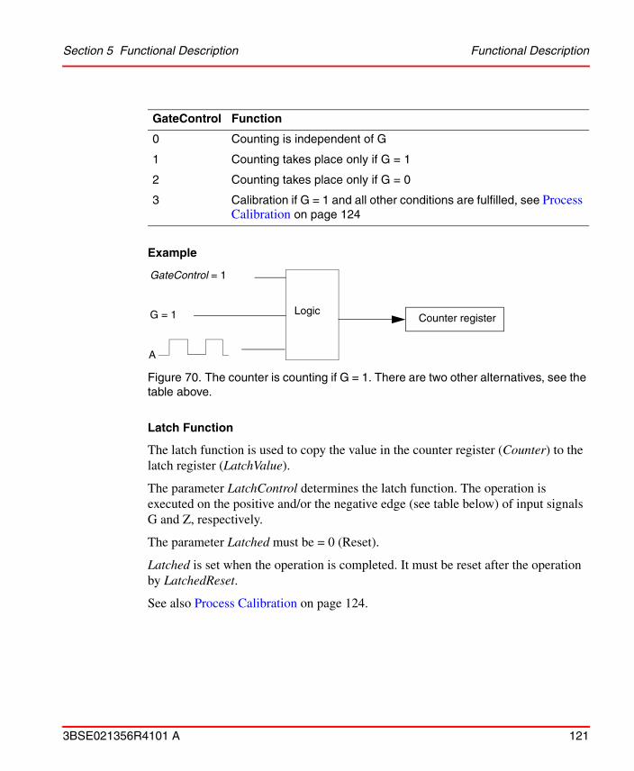
Section 5 Functional Description Functional Description
3BSE021356R4101 A 121
Example
Figure 70. The counter is counting if G = 1. There are two other alternatives, see the table above.
Latch Function
The latch function is used to copy the value in the counter register (Counter) to the latch register (LatchValue).
The parameter LatchControl determines the latch function. The operation is executed on the positive and/or the negative edge (see table below) of input signals G and Z, respectively.
The parameter Latched must be = 0 (Reset).
Latched is set when the operation is completed. It must be reset after the operation by LatchedReset.
See also Process Calibration on page 124.
GateControl Function
0 Counting is independent of G
1 Counting takes place only if G = 1
2 Counting takes place only if G = 0
3 Calibration if G = 1 and all other conditions are fulfilled, see Process Calibration on page 124
GateControl = 1
G = 1 Counter register
A
Logic

Functional Description Section 5 Functional Description
122 3BSE021356R4101 A
Example
Figure 71. The counter value is copied to the latch register on the positive edge of input signal G. There are 3 other alternatives, see table above.
Limitation Function
If the control bit RangeLimited = 1, then the counter is counting up to the preset value and will then restart from 0. Counting down results in the counter attaining the preset value on the next pulse, if the current counter value = 0.
RangeLimited = 0 corresponds to RangeLimited = 1 if the preset value = FFFF(hex) = 65535(dec).
The flag PresetReached is set when the counter value is equal to the preset value. This flag must be reset by PresetReset after the operation.
LatchControl Function
0 Save the counter value on the positive edge of input signal Z.For its use, see Process Calibration on page 124
1 Save the counter value on the positive edge of input signal G
2 Save the counter value on the negative edge of input signal G
3 Save the counter value on both the positive and negative edges of input signal G
LatchControl = 1
Latched = 0 Latched = 1
Counter register
Latch registerG
Logic

Section 5 Functional Description Functional Description
3BSE021356R4101 A 123
Figure 72. Limitation function example.
Digital Low-pass Filter Function
Programmable digital low-pass filters can be connected to the A inputs. The selected filter constant is common for the two A inputs.
The filter function is only available if CounterMode = 0 (pulse counting).
Figure 73. A filter can be connected between the A input and the counter register.
If the preset register value = 0, then the counter retains the value 0.
RangeLimited = 1
Counter = PresetValue
Counter register
Value 0
RangeLimited = 1
Counter = 0
Counter register
Preset register
Count up pulse (+)
Count down pulse (–)
Logic
Logic
CounterMode = 0FilterEnable
FilterConstant
Counter register
Logic
FilterA

Functional Description Section 5 Functional Description
124 3BSE021356R4101 A
The control bit FilterEnable enables the filter function for each counter individually. The filter will be connected to the input A if the bit is set. The parameter FilterConstant is used to select the filter constant value, see table below. Note that there are two filters but the constant value is common for the two filters.
Process Calibration
Process calibration of the counter is performed in order to synchronize the control system with the machinery where the pulse transmitter is mounted. This means, that the counter is set to a preset value when a reference pulse is received. Input Z is used to activate calibration. The input signal to Z can, for example, be a zero pulse integrated with an incremental encoder. Alternatively, the calibration signal may come from another transmitter which is independent of the pulse transmitter. Calibration is performed at the first positive edge of the input signal Z and is therefore independent of the signal duration at Z. It does not matter if it corresponds to several pulses in the A and B signals, or if several Z pulses are given during the allowed calibration time. Calibration may be initiated by the control system or by an external signal.
Calibration is enabled if CalEnable = 1 or if GateControl = 3 and G input = 1. The counter direction must also coincide with CalDirection, and Calibrated must be = 0 (acknowledged by a positive edge on CalReset). When calibration is activated, the counter is given the value in PresetValue and Calibrated will be set. The counter value before loading, can be saved in LatchValue if LatchControl = 0 and Latched = 0 (see below). Note, that the condition for the latch function is not dependent on the direction and therefore does not automatically occur on that edge of Z, which activates calibration.
The example below illustrates the use of the signals involved in the calibration.
FilterConstant Function
0 73.5 kHz or minimum 0.007 ms pulse width
1 37.8 kHz or minimum 0.013 ms pulse width
2 12.8 kHz or minimum 0.04 ms pulse width
3 1.2 kHz or minimum 0.4 ms pulse width

Section 5 Functional Description Functional Description
3BSE021356R4101 A 125
Process calibration, alternative 1
Calibration is enabled by the flag CalEnable, which should be enabled by the control system. The preset value is copied to the counter register at a positive edge on input signal Z. The old counter register value is saved in the latch register for evaluation.
The calibration direction is determined by CalDirection (0 = positive direction, 1 = negative direction).
Calibrated, Latched and PresetReached should be reset after calibration (with CalReset, LatchedReset and PresetReset).
Figure 74. Process calibration example 1.
Process calibration, alternative 2
Calibration is enabled by input G if GateControl = 3 and Calibrated = 0. The preset value is copied to the counter register at a positive edge on input signal Z. The old counter register value in the latch register is saved for evaluation.
The calibration direction is determined by CalDirection (0 = positive direction, 1 = negative direction).
Calibrated, Latched and PresetReached should be reset after calibration (with CalReset, LatchedReset and PresetReset).
CalEnable = 1CalDirection = Direction of the latest count pulseCalibrated = 0
Calibrated = 1PresetReached = 1
Preset register
Counter registerZ
LatchControl = 0Latched = 0
Latched = 1
Latch registerZ
Counter register
Logic
Logic

200-IP2 Connections Section 5 Functional Description
126 3BSE021356R4101 A
Figure 75. Process calibration example 2.
200-IP2 Connections
The unit is used for pulse transmitters with a nominal voltage of 12–24 V DC. An external power supply must be connected via a power line filter to the screw terminals (note that there are general demands on all connected units for CE marking with respect to the EMC and LVD approval). The type of filter is specified in Appendix B, Recommended Components on page 333. If galvanic insulation is not required for the connected pulse transmitters, then the power supply can be connected to the individual pulse transmitter via terminals on the baseplate of the pulse counter. Separate power supplies can be used for the pulse transmitters and the pulse counter unit, as the signal inputs are optocoupled and galvanically insulated. This also applies for transmitters using different voltages.
Connect the different inputs to the corresponding numbered connections as shown in the figure below.
GateControl = 3CalDirection = Direction of the latest count pulseCalibrated = 0G = 1
Calibrated = 1PresetReached = 1
Preset register
Counter register
Z
LatchControl = 0Latched = 0
Latched = 1
Latch registerZ
Counter register
Logic
Logic

Section 5 Functional Description 200-IP2 Connections
3BSE021356R4101 A 127
Figure 76. Example of wiring with a pulse transmitter with one pulse train. For connection of a second pulse transmitter to the baseplate, see the table below. The dotted lines indicate signals which are not always used. Note, that not all baseplates have three rows.
Connection to the baseplate terminals
Upper row
Middle row
Lower row
0 1 2
Signal inputs
12/24 V DC
0 V DC
Signal for counter gate
Signal for counter calibration/preset
Signal for up/down counting
-(G)+-(Z)+-(B)+-(A)+
3 4 5 6 7
16 17 18 19 20 21 22 23
34 35 36 37 38 39 40 41
External power supply12–24 V DC
-
+
Pulse counter interface 0
15
33
51
Terminal no.
Filter

200-IP2 Connections Section 5 Functional Description
128 3BSE021356R4101 A
Figure 77. Example of wiring with an incremental encoder with 2 pulse trains, with or without zero reference, and/or gate function. For connection of a second incremental encoder to the baseplate, see the table below. The dotted lines indicate signals which are not always used. Note, that not all baseplates have three rows.
Connection to the baseplate terminals
Upper row
Middle row
Lower row
0 1 2
Signal inputs
12/24 V DC
0 V DC
-(G)+-(Z)+-(B)+-(A)+
3 4 5 6 7
16 17 18 19 20 21 22 23
34 35 36 37 38 39 40 41
External power supply12–24 V DC
-
+
Pulse counter interface 0
15
33
51
Terminal no.
Filter

Section 5 Functional Description 200-IP2 Connections
3BSE021356R4101 A 129
Screw Terminal connections
200-TB2 & 200-TB3(TB3 is the recommended type)
200-TBN & 200-TBNF
Terminals to be connected
Signal(upper row)
0 V DC(middle row)
12/24 V DC(lower row)
Signal
Pulse counter interface 0
A+ 0 17 35 0
A- 1 18 36 1
B+ 2 19 37 2
B- 3 20 38 3
Z+ 4 21 39 4
Z- 5 22 40 5
G+ 6 23 41 6
G- 7 24 42 7
Pulse counter interface 1
A+ 8 25 43 8
A- 9 26 44 9
B+ 10 27 45 10
B- 11 28 46 11
Z+ 12 29 47 12
Z- 13 30 48 13
G+ 14 31 49 14
G- 15 32 50 15
0 V DC 16–33 16, 33
12/24 V DC 34–51 34, 51

Temperature Precautions Section 5 Functional Description
130 3BSE021356R4101 A
Power can be supplied to the encoders from the middle and lower row (marked COM and V, respectively) of the baseplate, or from a separate power supply.
If a non-complementary transmitter is used, its 0 V reference is connected to the minus terminal (–), and the signal to the plus terminal (+). Both complementary and non-complementary transmitters can be used in the same counter, as all the inputs are individually galvanically insulated. Complementary electronic transmitters should be used if long wires are used, and maximum noise immunity is required. They should also be used to avoid contact bounce problems. Complementary signals give better noise suppression.
200-IP2 can be used with transmitters giving a maximum pulse frequency of 100 kHz, which means that mechanical transmitters should not be used. Such transmitters generate contact bounces, which may be counted by this high-speed counter. Use electronic pulse transmitters instead.
Not connected signal inputs are detected as “Input OFF” (inactive).
To fulfil EMC demands, the connection cable to the transmitter must be shielded using a twisted-pair cable, one for each complementary input signal. The shield must be connected close to the pulse counter unit, using a ground clamp.
Temperature Precautions
Certain environmental temperature precautions should be considered if the absolute maximum allowed input voltage specified for 200-IP2 is supplied to many inputs simultaneously. This may occur if the inputs are connected to digital switches for 24V DC.
To minimize temperature rise and thus extend the unit life, it is recommended not to connect maximum input voltage simultaneously to all inputs for extended periods of time at maximum allowed environmental temperature (+55 ºC momentarily or +50 ºC average for over 24 hours).
If the ambient temperature is expected to exceed 40 ºC, input signal voltage exceeding 20 V can easily be limited to a lower voltage using a series resistor which could be mounted on the input signal terminal block. Recommended resistor value is 1 kΩ. Typically a 1 kΩ series resistor limits a 24 V sensor signal to approximately 15 V at the 200-IP2 input, which still safely meets the minimum level for an active input.
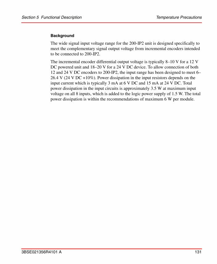
Section 5 Functional Description Temperature Precautions
3BSE021356R4101 A 131
Background
The wide signal input voltage range for the 200-IP2 unit is designed specifically to meet the complementary signal output voltage from incremental encoders intended to be connected to 200-IP2.
The incremental encoder differential output voltage is typically 8–10 V for a 12 V DC powered unit and 18–20 V for a 24 V DC device. To allow connection of both 12 and 24 V DC encoders to 200-IP2, the input range has been designed to meet 6–26.4 V (24 V DC +10%). Power dissipation in the input resistors depends on the input current which is typically 3 mA at 6 V DC and 15 mA at 24 V DC. Total power dissipation in the input circuits is approximately 3.5 W at maximum input voltage on all 8 inputs, which is added to the logic power supply of 1.5 W. The total power dissipation is within the recommendations of maximum 6 W per module.

Frequency Counter Unit 200-IP4 Section 5 Functional Description
132 3BSE021356R4101 A
Frequency Counter Unit 200-IP4The Frequency Counter Unit, 200-IP4, is an I/O unit with 4 pulse transmitter interfaces, each with 2 optocoupled inputs. The maximum pulse frequency is 100 kHz. The I/O unit is configured using the control system program.
200-IP4 can be adapted for a wide range of applications, for example, for counting pulses from flow meters and density meters. Quantity counting and speed calculation are examples of other applications.
200-IP4 has two 16-bit counters per channel. Each of the four interfaces can be individually configured for:
• time period measurement using one 16-bit counter and accumulating pulse counting using the other 16-bit counter.
• time period measurement using a 32-bit counter.
An internal clock (1 or 10 MHz) is used for the time period measurement.
Front Panel
1 = Insertable label for labelling individual input designations2 = Status indicators
Figure 78. Frequency counter unit 200-IP4.
200-IP4 can be used with the version B or later of Adapter 200-ANN.
1
2

Section 5 Functional Description Front Panel
3BSE021356R4101 A 133
Indicators
Only the LEDs for one of the four interfaces are shown in the table below.
Indication Function
Yellow LED, lit when the input is active.
N Yellow LED, lit when the input is configured for 16-bit time period measurement and a 16-bit accumulating pulse counter function.
D Yellow LED, lit when input is configured for 32-bit time period measurement.
OK Red LED, lit during the initialization phase, after the power has been switched on.
Green LED, lit when initialization of the 200-IP4 internal logic is complete.
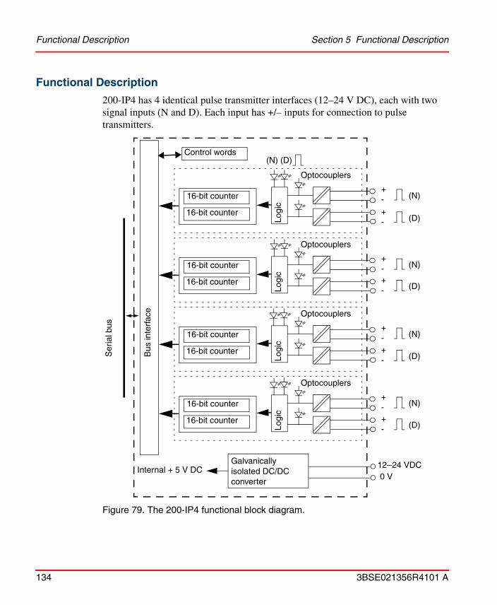
Functional Description Section 5 Functional Description
134 3BSE021356R4101 A
Functional Description
200-IP4 has 4 identical pulse transmitter interfaces (12–24 V DC), each with two signal inputs (N and D). Each input has +/– inputs for connection to pulse transmitters.
Figure 79. The 200-IP4 functional block diagram.
+-16-bit counter
16-bit counter
Logi
c
Optocouplers
Bus
inte
rfac
e
Ser
ial b
us
Galvanically isolated DC/DC converter
12–24 VDC0 V
Internal + 5 V DC
Control words
16-bit counter
16-bit counterLo
gic
Optocouplers
16-bit counter
16-bit counter
Logi
c
Optocouplers
16-bit counter
16-bit counter
Logi
c
Optocouplers
(N)
+- (D)
+- (N)
+- (D)
+- (N)
+- (D)
+- (N)
+- (D)
(N) (D)

Section 5 Functional Description Functional Description
3BSE021356R4101 A 135
Each of the four interfaces can be individually configured for:
• time period measurement using one 16-bit counter and accumulating pulse counting using the other 16-bit counter (the N-input is to be used).
• time period measurement using a 32-bit counter (the D-input is to be used).
Figure 80. Individual configuration of interfaces.
The configuration is selected by setting “SW” in the appropriate position (variable SelectMeasureType). The arrows show signals (control words and registers) controlled by the control system.
The internal clock (1 or 10 MHz) is used for the time period measurement.
The number of periods for which the input signal is to be measured is selectable (1, 2, 4, 8, 16, 32, 64 or 128 periods). See Gate control in the figure above.
The unit can be configured for a number of applications. This is done via parameters accessible from the control system program.
The power to the 200-IP4 is supplied by an external power supply (12–24 V DC), connected to the screw terminal of the I/O unit.
Gate control1-128 periods 16-bit counter16-bit counter&
Clock1 MHz10 MHz
SW
Gate control1–128 periods 16-bit counter16-bit counter&
Clock1 MHz10 MHz
SW
N input
D input

Functional Description Section 5 Functional Description
136 3BSE021356R4101 A
Variables
Communication between the 200-IP4 unit and the control system takes place via variables accessible in the control system program. Such variables are, for example, selection of clock frequency (ClockFrequency) and the selection of measurement type (SelectMeasureType). Control words are used to set parameters for the unit configuration. The control words which are sent to the frequency counter unit, can be read back to the control system to allow verification that (at least) one I/O scan has been performed since the control system cycle which initiated the 200-IP4 command.
Select type of measurement
200-IP4 can be configured for two alternative functions using the variable SelectMeasureType. Each of the four input channels can be configured individually.
Control word variables are written in italics, making it easier to recognize them. Example: SelectMeasureType, ClockFrequency, etc.
Only one of the four identical frequency counter interfaces is described in this section. This means that the interface number of the variables has been omitted, for example, SelectMeasureType0 and SelectMeasureType1 are the parameters SelectMeasureType for interfaces 0 and 1, respectively.
SelectMeasureType Function
0 Time period measurement using a 16-bit counter register and the function of a 16-bit accumulating counter
1 Time period measurement using a 32-bit counter register

Section 5 Functional Description Functional Description
3BSE021356R4101 A 137
Start time period measurement
Check if the time period measurement is complete
After a complete measurement the flag MeasurementReady is set.
MeasurementReady is reset by the 200-IP4 unit when a positive edge of StartMeasurement is received.
Select clock frequency
The clock frequency (for the time period measurement resolution selection) can be set to 1 or 10 MHz using the variable ClockFrequency.
The control bit StartMeasurement starts one measurement of the time period.
StartMeasurement Function
0 Time period measurement stopped (not enabled)
1 Time period measurement starts on the positive edge of the variable
MeasurementReady Function
0 The measurement is not complete
1 The positive edge of the flag indicates that the measurement is complete
ClockFrequency Function
0 Clock frequency = 10 MHz
1 Clock frequency = 1 MHz

Functional Description Section 5 Functional Description
138 3BSE021356R4101 A
Select number of time periods
The number of time periods to be measured can be selected using the variable NumberOfPeriods.
Time period measurement
The time period measurement described below is valid for a 16-bit or 32 bit measurement (SelectMeasureType 0 or 1).
NumberOfPeriods Function
0 Measure for 1 period
1 Measure for 2 periods
2 Measure for 4 periods
3 Measure for 8 periods
4 Measure for 16 periods
5 Measure for 32 periods
6 Measure for 64 periods
7 Measure for 128 periods
For SelectMeasureType 0 (16-bit measurement) the minimum input frequency from a pulse transmitter is 15.3 Hz. At lower frequencies the counter will overflow every 65 ms. To measure frequencies below 15.3 Hz, the overflow must be detected and counted by the software. The counter value is always available via the Serial Bus, which means that an overflow can be detected by reading the counter every 30 ms. This means, there is in practice, no lower limit for the input frequency.

Section 5 Functional Description Functional Description
3BSE021356R4101 A 139
Figure 81. Time period measurement.
Signal Function
StartMeasurement The raising edge of StartMeasurement will start a new measuring sequence. The measuring function is independent of the length of StartMeasurement.Note. StartMeasurement must not be set to 1 and then reset to 0 during the same Serial Bus scan.
MeasurementReady MeasurementReady will be set to 1 on the falling edge of “Enable”, i.e. when the counter is stopped and a new stable value is available. MeasurementReady will be reset to 0 on the raising edge of StartMeasurement.
Enable “Enable” is an internal signal of 200-IP4, which is generated from the input pulses and StartMeasurement. The length of “Enable” is selected by NumberOfPeriods, to be 1, 2, 4, ... up to 128 periods of the input signal.
Input Input signal to an 200-IP4 channel, which is coming from a pulse transmitter.
Counting (1 or 10 MHz clock)
StartMeasurement
MeasurementReady
Enable
Input

200-IP4 Connections Section 5 Functional Description
140 3BSE021356R4101 A
Reset of Counter
The accumulating pulse counter, which is available if SelectMeasureType = 0 (see Select type of measurement on page 136), can be reset by the control bit ResetCounter. The counter is reset on the positive edge of ResetCounter and goes on counting (from 0) after this edge.The positive edge of the flag ResetDone is an acknowledgement that the counter has been reset. Use this flag in the control system to set bit ResetCounter to 0. ResetDone is automatically reset on the negative edge of ResetCounter.
Figure 82. The 16-bit accumulating counter can be reset if SelectMeasureType = 0.
200-IP4 Connections
The unit is used for pulse transmitters with a nominal voltage of 12–24 V DC. An external power supply must be connected via a power-line filter to the screw terminals (note that there is a general demand for CE marking with respect to EMC and LVD approval for all units). The type of filter is specified in Appendix B, Recommended Components on page 333. If galvanic insulation is not required for the connected pulse transmitters, then the power supply can be connected to the individual pulse transmitter via terminals on the base plate of the frequency counter. Separate power supplies can be used for the pulse transmitters and the frequency counter unit, as the signal inputs are optocoupled and galvanically insulated. This also applies for transmitters using different voltages.
Connect the different inputs to the corresponding numbered connections as shown in the figure below.
ResetCounter
ResetDone
16-bit counter
1
ResetCounter
ResetDone
Counter value2 0 2 4 6

Section 5 Functional Description 200-IP4 Connections
3BSE021356R4101 A 141
Connections used for 16-bit time period measurement
The following connections are to be used if the configuration for 16-bit time period measurement and a 16 bit accumulating counter is selected.
Figure 83. Connections for 16-bit time period measurement and a 16-bit accumulating pulse counter in all 4 channels.
Connection to the baseplate terminals
Upper row
Middle row
Lower row
0 1 2
Signal inputs
12/24 V DC
0 V DC
Channel 3
Channel 2
Channel 1
Channel 0
-(N)+-(N)+-(N)+-(N)+
3 4 5 6 7
16 17 18 19 20 21 22 23
34 35 36 37 38 39 40 41
External power supply12–24 V DC
-
+
15
33
51
Terminal no.
Filter
16-bit time per measurem. + 16 bit acc. counter
Channel 3

200-IP4 Connections Section 5 Functional Description
142 3BSE021356R4101 A
Connections used for 32-bit time period measurement
The following connections are used if the configuration for 32-bit time period measurement is selected.
Figure 84. Connections for 32-bit time period measurement in all 4 channels.
Connection to the baseplate terminals
Upper row
Middle row
Lower row
8 9 10
Signal inputs
12/24
0 V DC
Channel 3
Channel 2
Channel 1
Channel 0
-(D)+-(D)+-(D)+-(D)+
11 12 13 14 15
24 25 26 27 28 29 30 31
42 43 44 45 46 47 48 49
External power supply12–24 V DC
-
+
1
33
Terminal no.
Filter
32-bit time period measurement
3216
34V DC
50 51

Section 5 Functional Description 200-IP4 Connections
3BSE021356R4101 A 143
Screw terminal connections
Power can be supplied to the transmitters from the middle and lower row (marked COM and V, respectively) of the baseplate, or from a separate power supply.
Channel Input
200-TB2 & 200-TB3(TB3 is the recommended type)
200-TBN & 200-TBNF
Connections to be connected
Signal(upper row)
0 V DC(middle row)
12/24 V DC(lower row) Signal
0 N+ 0 17 35 0
0 N- 1 18 36 1
1 N+ 2 19 37 2
1 N- 3 20 38 3
2 N+ 4 21 39 4
2 N- 5 22 40 5
3 N+ 6 23 41 6
3 N- 7 24 42 7
0 D+ 8 25 43 8
0 D- 9 26 44 9
1 D+ 10 27 45 10
1 D- 11 28 46 11
2 D+ 12 29 47 12
2 D- 13 30 48 13
3 D+ 14 31 49 14
3 D- 15 32 50 15
0 V DC 16–33 16, 33
12/24 V DC 34–51 34, 51
200-IP4 can be used with transmitters giving a maximum pulse frequency of 100 kHz, which means that mechanical transmitters should not be used. Such transmitters generate contact bounces, which may be counted by this high-speed counter. Use electronic pulse transmitters instead.

Temperature Precautions Section 5 Functional Description
144 3BSE021356R4101 A
Not connected signal inputs are detected as “Input OFF” (inactive).
To fulfil EMC demands, the connection cable to the transmitter must be shielded using a twisted-pair cable, one for each input signal. The shield must be connected close to the frequency counter unit, using a ground clamp.
Temperature Precautions
Certain environmental temperature precautions should be considered if the absolute maximum allowed input voltage specified for 200-IP4 is supplied to many inputs simultaneously. This may occur if the inputs are connected to digital switches for 24 V DC.
To minimize temperature rise and thus extend the unit life, it is recommended not to connect maximum input voltage simultaneously to all inputs for extended periods of time at maximum allowed environmental temperature (+55 ºC momentarily or +50 ºC average for over 24 hours).
If the ambient temperature is expected to exceed 40 ºC, input signal voltage exceeding 20 V can easily be limited to a lower voltage using a series resistor which could be mounted on the input signal terminal block. Recommended resistor value is 1 kΩ. Typically a 1 kΩ series resistor limits a 24 V sensor signal to approximately 15 V at the 200-IP4 input, which still safely meets the minimum level for an active input.
Background
The wide signal input voltage range for the 200-IP4 unit is designed specifically to meet the complementary signal output voltage from incremental encoders intended to be connected to 200-IP4.
The incremental encoder differential output voltage is typically 8–10 V for a 12 V DC powered unit and 18–20 V for a 24 V DC device. To allow connection of both 12 and 24 V DC encoders to 200-IP4, the input range has been designed to meet 6–26.4 V (24 V DC +10%). Power dissipation in the input resistors depends on the input current which is typically 3 mA at 6 V DC and 15 mA at 24 V DC. Total power dissipation in the input circuits is approximately 3.5 W at maximum input voltage on all 8 inputs, which is added to the logic power supply of 1.5 W. The total power dissipation is within the recommendations of maximum 6 W per module.

Section 5 Functional Description Analog Input Unit 200-IE8
3BSE021356R4101 A 145
Analog Input Unit 200-IE8200-IE8 is an I/O unit for 8 analog input signals. The inputs are filtered and the unit is galvanically insulated. The unit has 12 bit resolution. Each of the inputs can be either a voltage (0–10 V DC, ± 10 V DC) or a current (0–20 mA, 4–20 mA) input.
1 = Holder for insertable label for individual input designations2 = Power ON indicator
Figure 85. Analog input unit 200-IE8.
Front Panel
Indicators
Functional Description
The 8 analog input signals are connected to the unit via the screw terminals on the terminal base unit.
The inputs are as a group of eight galvanically isolated from the serial bus by optocouplers and the 8 inputs are single ended.
Indication Function
PWR Green LED, lit when 24 V DC power is ON
2
1

Functional Description Section 5 Functional Description
146 3BSE021356R4101 A
Selection of voltage or current is made on the terminal base unit for each input. It is possible to connect either voltage or current to the input but not both simultaneously. Selection must also be set by the programming software.
Power for the internal logic is provided via an external power supply.
Figure 86. The 200-IE8 functional block diagram.
Numbers within parentheses in the diagram refer to signal terminals on the terminal base unit, (e.g. 200-TB3) connected to the I/O unit. Note that screw terminals 35–50 only exist on 200-TB3. Terminals 17–32 do not exist on 200-TBN and 200-TBNF.
Since 200-IE8 does not receive power from the terminal base unit, 24 V DC must be applied to the unit before operation. If power is not applied, the unit position will appear to the adapter as an empty terminal base.
PWRDC/DC-converter
Channel 0
Channel 1
Channel 7
A/D
-con
vert
erBus
inte
rfac
e
Ser
ial b
us
Optocouplers
+24 V DC (34–51)
0 V DC (16–33)
Voltage V (1)
Current I (0)
0 V DC (18)
0 V DC (17)

Section 5 Functional Description 200-IE8 Connections
3BSE021356R4101 A 147
200-IE8 Connections
Connect individual input wiring to numbered terminals as described in the table below. Always use shielded twisted-pair cables.
Figure 87. Wiring examples. Note that not all terminal base units have three rows.
Upper row
Middle row
Lower row
0 1 2
16 17 18
34 35 36
Inputs
+ 24 V DC
0 V DC
I+ -
+ -
Out
PWR
0–20 mA current transducer
Upper row
Middle row
Lower row
0 1 2
16 17 18
34 35 36
Inputs
+ 24 V DC
0 V DC+ -
+ -
Out
PWR
voltage transducer
Upper row
Middle row
Lower row
0 1 2
16 17 18
34 35 36
Inputs
+ 24 V DC
0 V DC
u+ -
+ -
Out
PWR
voltage transducer
transducer powered from the system
external power supply
external power supply
4–20 mA
16 17 18
34 35 36
Out
current transducer
4–20 mA
IIn
u
4–20 mA
16 17 18
34 35 36
Inputs
+ 24 V DC
0 V DC
Out
current transducer
In
Inputs
+ 24 V DC
0 V DC+ -
0–20 mA0 1 2 0 1 2
I

200-IE8 Connections Section 5 Functional Description
148 3BSE021356R4101 A
Screw terminal connections
Input
200-TB2 & 200-TB3200-TBN & 200-TBNF
Terminals to be connected
Signal(upper row)
0 V DC(middle row)
24 V DC(lower row)
Signal
Current 0 0 17 35 0
Voltage 0 1 18 36 1
Current 1 2 19 37 2
Voltage 1 3 20 38 3
Current 2 4 21 39 4
Voltage 2 5 22 40 5
Current 3 6 23 41 6
Voltage 3 7 24 42 7
Current 4 8 25 43 8
Voltage 4 9 26 44 9
Current 5 10 27 45 10
Voltage 5 11 28 46 11
Current 6 12 29 47 12
Voltage 6 13 30 48 13
Current 7 14 31 49 14
Voltage 7 15 32 50 15
0 V DC 16–33 16, 33
+24 V DC 34–51 34, 51

Section 5 Functional Description Analog Output Unit 200-OE4
3BSE021356R4101 A 149
Analog Output Unit 200-OE4200-OE4 is an I/O unit for 4 analog output signals. The unit is galvanically isolated. The unit has 12 bit resolution. Each of the outputs can be either a voltage (0–10 V DC, ± 10 V DC) or a current (0–20 mA, 4–20 mA) output.
1 = Holder for insertable label for individual output designations2 = Power ON indicator.
Figure 88. Analog output unit 200-OE4.
Front Panel
Indicators
Functional Description
The 4 analog output signals are connected to the unit via the screw terminal on the terminal base unit.
The outputs are arranged in a group of four, galvanically isolated from the serial bus by optocouplers.
Indication Function
PWR Green LED, lit when 24 V DC power is ON
1
2

Functional Description Section 5 Functional Description
150 3BSE021356R4101 A
Selection of voltage or current is made on the terminal base unit for each output. This means that one output can be selected for current and another for voltage output. It is possible to connect either voltage or current to the input but not both simultaneously. Selection must also be set in the programming software.
Power for the internal logic is provided via an external power supply.
Figure 89. The 200-OE4 functional block diagram.
Numbers within parentheses in the diagram refer to signal terminals on the terminal base unit, (e.g. 200-TB3) connected to the I/O unit. Note that screw terminals 35–50 only exist on 200-TB3. Terminals 17–32 do not exist on 200-TBN and 200-TBNF.
Since 200-OE4 does not receive power from the terminal base unit, 24 V DC must be applied to the unit before operation. If power is not applied, the unit position will appear to the adapter as an empty terminal base. Minimum resistive load on mA output is 15 Ω.
A-versions only. Select range 0–20 mA for not connected outputs (to avoid voltage or current on the output pins).
DC/DC-converter
Voltage/current converter
PWR
Channel 0
Channel 1
Channel 3
Optocoupler
Bus
Inte
rface
Ser
ial b
us
+24 V DC (35–51)
0 V DC (16–33)
Voltage V (2)Voltage Return (3)
Current 1 (0)
Current Return (1)
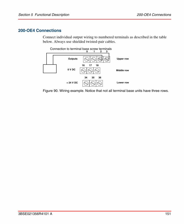
Section 5 Functional Description 200-OE4 Connections
3BSE021356R4101 A 151
200-OE4 Connections
Connect individual output wiring to numbered terminals as described in the table below. Always use shielded twisted-pair cables.
Figure 90. Wiring example. Notice that not all terminal base units have three rows.
0 1 2
16 17 18
34 35 36
3
+ 24 V DC
0 V DC
Upper row
Middle row
Lower row
Connection to terminal base screw terminals
Outputs

200-OE4 Connections Section 5 Functional Description
152 3BSE021356R4101 A
Screw terminal connections
Output
200-TB2 & 200-TB3 200-TBN & 200-TBNF
Terminals to be connected
Signal(upper row)
Signal
Current Signal 0 0 0
Current Return 0 1 1
Voltage Signal 0 2 2
Voltage Return 0 3 3
Current Signal 1 4 4
Current Return 1 5 5
Voltage Signal 1 6 6
Voltage Return 1 7 7
Current Signal 2 8 8
Current Return 2 9 9
Voltage Signal 2 10 10
Voltage Return 2 11 11
Current Signal 3 12 12
Current Return 3 13 13
Voltage Signal 3 14 14
Voltage Return 3 15 15
0 V DC 16–33 (middle row) 16, 33
+24 V DC 34–51 (lower row) 34, 51
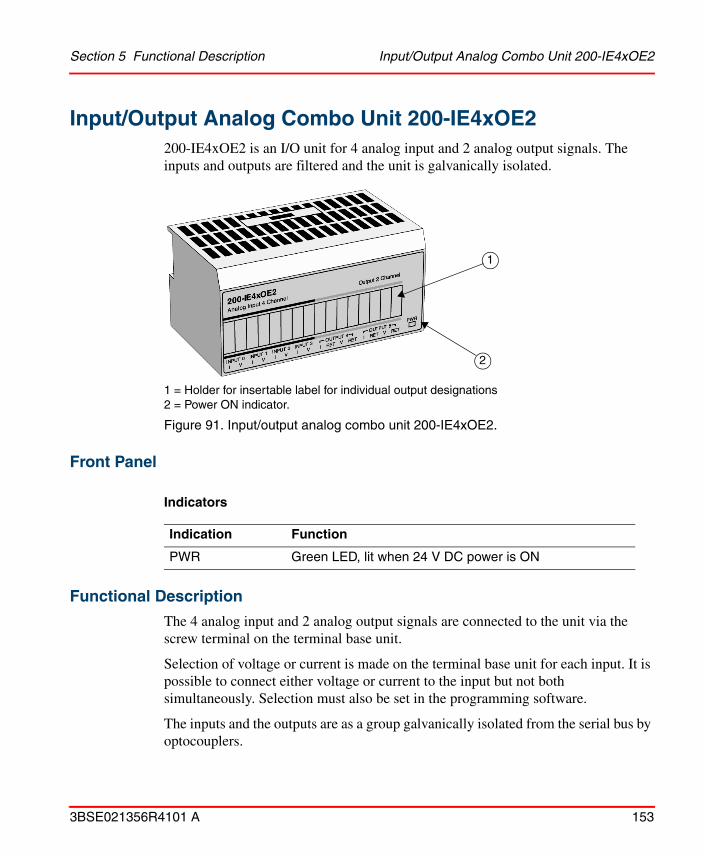
Section 5 Functional Description Input/Output Analog Combo Unit 200-IE4xOE2
3BSE021356R4101 A 153
Input/Output Analog Combo Unit 200-IE4xOE2200-IE4xOE2 is an I/O unit for 4 analog input and 2 analog output signals. The inputs and outputs are filtered and the unit is galvanically isolated.
1 = Holder for insertable label for individual output designations2 = Power ON indicator.
Figure 91. Input/output analog combo unit 200-IE4xOE2.
Front Panel
Indicators
Functional Description
The 4 analog input and 2 analog output signals are connected to the unit via the screw terminal on the terminal base unit.
Selection of voltage or current is made on the terminal base unit for each input. It is possible to connect either voltage or current to the input but not both simultaneously. Selection must also be set in the programming software.
The inputs and the outputs are as a group galvanically isolated from the serial bus by optocouplers.
Indication Function
PWR Green LED, lit when 24 V DC power is ON
1
2

Functional Description Section 5 Functional Description
154 3BSE021356R4101 A
Power for the internal logic is provided via an external power supply.
Figure 92. The 200-IE4xOE2 functional block diagrams.
Numbers in parentheses in the diagram, refer to signal terminals on the terminal base unit, (e.g. 200-TB3) to which the unit is connected. Note that screw terminals 35–50 only exist on 200-TB3. Terminals 17–32 do not exist on 200-TBN and 200-TBNF.
Since 200-IE4xOE2 does not receive power from the terminal base unit, 24 V DC must be applied to the unit before operation. If power is not applied, the unit position will appear to the adapter as an empty terminal base.
Channel 1
Channel 3
Channel 0
Channel 1
DC/DC-converter
PWR
Voltage/currentconverter
Bus
inte
rfac
e
A/D
-con
vert
er
Optocoupler
Ser
ial b
us
Channel 0
+24 V DC (34–51)
0 V DC (34–51)
Voltage V (1)
Current (0)
0 V DC (18)
0 V DC (17)
Voltage V (10)Voltage Return(11)
Current (8)
Current Return (9)

Section 5 Functional Description 200-IE4xOE2 Connections
3BSE021356R4101 A 155
200-IE4xOE2 Connections
Connect individual input/output wiring to numbered terminals as described in the table below. Always use shielded twisted-pair cables.
Figure 93. Wiring example.
Not all terminal base units have three rows. See also examples in 200-IE8 Connections on page 147.
0 ....... 8
16 17 18
34 35 36
9
+ 24 V DC
0 V DC
Upper row
Middle row
Lower row
Outputs

200-IE4xOE2 Connections Section 5 Functional Description
156 3BSE021356R4101 A
Screw terminal connections
Input/Output
200-TB2 & 200-TB3200-TBN & 200-TBNF
Terminals to be connected
Signal(upper row)
0 V DC(middle row)
24 V DC(lower row)
Signal
Input Current 0 0 17 35 0
Input Voltage 0 1 18 36 1
Input Current 1 2 19 37 2
Input Voltage 1 3 20 38 3
Input Current 2 4 21 39 4
Input Voltage 2 5 22 40 5
Input Current 3 6 23 41 6
Input Voltage 3 7 24 42 7
Output Current Signal 4 8 8
Output Current Return 4 9 9
Output Voltage Signal 4 10 10
Output Voltage Return 4 11 11
Output Current Signal 5 12 12
Output Current Return 5 13 13
Output Voltage Signal 5 14 14
Output Voltage Return 5 15 15
0 V DC 16–33 16, 33
+24 V DC 34–51 34, 51

Section 5 Functional Description Analog Input Unit 200-IF4I
3BSE021356R4101 A 157
Analog Input Unit 200-IF4I200-IF4I is an I/O unit for 4 analog input signals. The inputs are filtered and individually galvanically isolated. The unit has up to 16-bit resolution. Each of the inputs can be either a voltage (0–5 V DC, ± 5 V DC, 0–10 V DC, ± 10 V DC) or a current (0–20 mA, 4–20 mA) input.
1 = Holder for insertable label for individual input designations2 = Power ON indicator
Figure 94. Analog input unit 200-IF4I.
Front Panel
Indicators
Indication Function
OK Green LED,
1. Solid green when 24 V DC power is ON
2. Flashing green if the unit is not configured or there is a field-power fault
3. Solid red if there is no contact with the controller or there is a critical fault
2
1

Functional Description Section 5 Functional Description
158 3BSE021356R4101 A
Functional Description
The 4 analog input signals are connected to the unit via the screw terminals on the terminal base unit.
The inputs are individually galvanically isolated from the serial bus by optocouplers.
Selection of voltage or current is made on the terminal base unit for each input. It is possible to connect either voltage or current to the input but not both simultaneously. Selection must also be set in the programming software.
Power to the internal logic is provided via the Serial I/O bus, but to the analog parts external 24 V DC must be supplied.
If the 24 V DC supply fails, the current input will open.
Maximum 50 Hz supression of the input signal is obtained if the filter frequency is set to 300 Hz, and maximum 60 Hz supression is obtained if the filter frequency is set to 150 Hz (set from the programming software).

Section 5 Functional Description Functional Description
3BSE021356R4101 A 159
Figure 95. The 200-IF4I functional block diagram.
Numbers within parentheses in the diagram refer to signal terminals on the terminal base unit, (e.g. 200-TB3) connected to the I/O unit. Note that screw terminals 35–50 only exist on 200-TB3. Terminals 17–32 do not exist on 200-TBN or 200-TBNF.
Ser
ial I
/O b
us
Bus
in
terf
ace
A/D
conv
erte
r
Protection circuit
+15 V
IIN (0)
IIN RETURN (1)
VIN (2)
VIN RETURN (3)
Mic
ro
cont
rolle
r
DC/DCconverter
+24 V DC (34–51)0 V DC (16–33)
Optocouplers

200-IF4I Connections Section 5 Functional Description
160 3BSE021356R4101 A
200-IF4I Connections
Connect individual input wiring to numbered terminals as described in the table below. Always use shielded twisted-pair cables.
Figure 96. Wiring examples. Note that not all terminal base units have three rows.
Upper row
Middle row
Lower row
0 1 2
16 17 18
34 35 36
Inputs
+ 24 V DC
0 V DC
I+ -
+ -
Out
PWR
0–20 mA
Current transducer
Upper row
Middle row
Lower row
0 1 2
16 17 18
34 35 36
Inputs
+ 24 V DC
0 V DC+ -
+ -
Out
PWR
Voltage transducer
External power supply
External power supply
4–20 mA
16 17 18
34 35 36
Out
Current transducer
4–20 mA
IIn
u
4–20 mA
16 17 18
34 35 36
Inputs
+ 24 V DC
0 V DC
Out
Current transducer
In
Inputs
+ 24 V DC
0 V DC + -
0–20 mA0 1 2 0 1 2
I
24 V DC power supply
3
External power supply

Section 5 Functional Description 200-IF4I Connections
3BSE021356R4101 A 161
Screw terminal connections
Input
200-TB3, 200-TB3T(1), 200-TB3S, 200-TBN & 200-TBNF
(1) Terminals 39 through 46 are chassis grounded. Terminals 36, 37, 38 and 47, 48, 49 are used for cold junction compensation.
Terminals to be connected
Signal (upper row)
Current Signal 0 0
Current Return 0 1
Voltage Signal 0 2
Voltage Return 0 3
Current Signal 1 4
Current Return 1 5
Voltage Signal 1 6
Voltage Return 1 7
Current Signal 2 8
Current Return 2 9
Voltage Signal 2 10
Voltage Return 2 11
Current Signal 3 12
Current Return 3 13
Voltage Signal 3 14
Voltage Return 3 15
0 V DC 200-TB3 – 16 thru 33(2) (middle row)200-TB3T – 17, 18, 33
200-TBN, 200-TBNF – 16 and 33
(2) Terminals 16 through 33 are internally connected in the terminal base unit.
+24 V DC 200-TB3 – 34 thru 51 (lower row)200-TB3T – 34, 35, 50, 51
200-TBN, 200-TBNF – 34 and 51

Analog Output Unit 200-OF4I Section 5 Functional Description
162 3BSE021356R4101 A
Analog Output Unit 200-OF4I200-OF4I is an I/O unit for 4 analog output signals. The outputs are individually galvanically isolated. The unit has 15 bits + sign resolution. Each of the outputs can be either a voltage (0–5 V DC, ± 5 V DC, 0–10 V DC, ± 10 V DC) or a current (0–20 mA, 4–20 mA) output.
1 = Holder for insertable label for individual output designations2 = Power ON indicator.
Figure 97. Analog output unit 200-OF4I.
Front Panel
Indicators
Indication Function
OK Green LED,
1. Solid green when 24 V DC power is ON.
2. Flashing green if the unit is not configured or there is a field-power fault.
3. Solid red if there is no contact with the controller or there is a critical fault.
1
2

Section 5 Functional Description Functional Description
3BSE021356R4101 A 163
Functional Description
The 4 analog output signals are connected to the unit via the screw terminal on the terminal base unit.
The outputs are individually galvanically isolated from the serial bus by optocouplers.
Selection of voltage or current is made on the terminal base unit for each output. It is possible to connect either voltage or current to the output but not both simultaneously. Selection must also be set in the programming software.
Power to the internal logic is provided via the Serial I/O bus, but to the analog parts external 24 V DC must be supplied.
Figure 98. The 200-OF4I functional block diagram.
Numbers within parentheses in the diagram refer to signal terminals on the terminal base unit, (e.g. 200-TB3) connected to the I/O unit. Note that screw terminals 35–50 only exist on 200-TB3. Terminals 17–32 do not exist on 200-TBN or 200-TBNF.
Ser
ial I
/O b
us
Bus
in
terfa
ce
D/A
conv
erte
rV/I
converterIOUT (0)
IOUT RETURN (1)
VOUT (2)
VOUT RETURN (3)
Mic
ro-
cont
rolle
r
DC/DCconverter
+24 V DC (34–51)0 V DC (16–33)
Protection circuit
Opto-couplers

200-OF4I Connections Section 5 Functional Description
164 3BSE021356R4101 A
200-OF4I Connections
Connect individual output wiring to numbered terminals as described in the table below. Always use shielded twisted-pair cables.
Figure 99. Wiring example. Note that not all terminal base units have three rows.
0 1 2
16 17 18
34 35 36
3
+ 24 V DC
0 V DC
Upper row
Middle row
Lower row
Connection to terminal base screw terminals
OutputsI
0 1 2
16 17 18
34 35 36
3
+ 24 V DC
0 V DC
Upper row
Middle row
Lower row
Outputs
Voltage output
Current output

Section 5 Functional Description 200-OF4I Connections
3BSE021356R4101 A 165
Screw terminal connections
Input
200-TB3, 200-TB3T(1), 200-TB3S, 200-TBN & 200-TBNF
(1) Terminals 39 through 46 are chassis grounded.
Terminals to be connected
Signal (upper row)
Current Signal 0 0
Current Return 0 1
Voltage Signal 0 2
Voltage Return 0 3
Current Signal 1 4
Current Return 1 5
Voltage Signal 1 6
Voltage Return 1 7
Current Signal 2 8
Current Return 2 9
Voltage Signal 2 10
Voltage Return 2 11
Current Signal 3 12
Current Return 3 13
Voltage Signal 3 14
Voltage Return 3 15
0 V DC 200-TB3 – 16 thru 33(2) (middle row)200-TB3T – 17, 18, 33
200-TBN, 200-TBNF – 16 and 33
(2) Terminals 16 through 33 are internally connected in the terminal base unit.
+24 V DC 200-TB3 – 34 thru 51 (lower row)200-TB3T – 34, 35, 50, 51
200-TBN, 200-TBNF – 34 and 51

RTD Input Unit 200-IR8 Section 5 Functional Description
166 3BSE021356R4101 A
RTD Input Unit 200-IR8200-IR8 is an I/O unit for eight 3-wire RTD input signals. The inputs have programmable filters and the unit is galvanically isolated. The unit has 16 bit resolution. A high number of sensor types are supported.
1 = Holder for insertable label for individual output designations2 = Power ON indicator.
Figure 100. RTD input unit 200-IR8.
Front Panel
Indicators
Indication Function
OK Bi-colour (green/red) LED
1. Steady red at power up.
2. Off while module performs diagnostic tests.
3. If tests are passed, flashing green as long as configuration words are zero.
4. Steady green when configured.
1
2

Section 5 Functional Description Sensor Types
3BSE021356R4101 A 167
Sensor Types
The following sensor types can be connected to 200-IR8:
Functional Description
The 8 analog input signals are connected to the unit via the screw terminal on the terminal base unit.
The inputs are as a group of 8 galvanically isolated from the serial bus by optocouplers. It is possible to deselect unused channels to improve system throughput. Periodic user calibration is supported.
Power for the internal logic is provided via an external power supply.
Sensor type α Temperature range
1–433 Ω
500 Ω Pt Euro 0.00385 -200 to +630°C
200 Ω Pt Euro 0.00385 -200 to +630°C
100 Ω Pt Euro 0.00385 -200 to +870°C
100 Ω Pt U.S. 0.00392 -200 to +630°C
500 Ω Ni 0.00618 -60 to +250°C
200 Ω Ni 0.00618 -60 to +250°C
120 Ω Ni 0.00672 -80 to +290°C
100 Ω Ni 0.00618 -60 to +250°C
10 Ω Cu 0.00427 -200 to +260°C
Since 200-IR8 does not receive power from the terminal base unit, 24 V DC must be applied to the unit before operation. If power is not applied, the unit position will appear to the adapter as an empty terminal base.

Functional Description Section 5 Functional Description
168 3BSE021356R4101 A
Figure 101. The 200-IR8 functional block diagram.
Numbers within parentheses in the diagram, refer to signal terminals on the terminal base unit, (e.g. 200-TB3) to which the unit is connected. Note that screw terminal numbers 35–50 only exist on 200-TB3. Terminals 17–32 do not exist on 200-TBN and 200-TBNF.
OK
DC/DC-converter
Voltage-reference
Bus
inte
rface
A/D
-con
vert
er
Ana
log
Mul
tiple
xer
Optocoupler Channel 0
Channel 1
Channel 7
+24 V DC (34)
0 V DC (16)
Low signal (0)Signal Return (17)
High signal (1)
Shield Return (18)

Section 5 Functional Description Filter and Unit Throughput
3BSE021356R4101 A 169
Filter and Unit Throughput
A programmable first notch filter in the analog to digital converter lets you select a frequency for the first notch of the filter. Selection of the filter influences the analog to digital output data rate and changes the unit throughput.
Figure 102. Filter response with first notch at 10 Hz.
Unit throughput means the time it takes for a signal at the input terminal to arrive at the serial bus. It is a function of:
• the selected programmable first notch filter frequency
• the number of channels actually configured for connection to a sensor.
First notch of filter (Hz) -3 dB frequency (Hz)
10 2.62
25 6.55
50 13.10
60 15.72
100 26.20
250 65.50
500 131.00
1000 262.00
Frequency – Hz
Gai
n –
dB

Filter and Unit Throughput Section 5 Functional Description
170 3BSE021356R4101 A
It is possible to select an enhanced mode of operation for this unit (selected by the software).
However, since the comparison is done each program scan, the result decreases unit throughput.This results in improved unit temperature drift characteristics and accuracy.
Throughput in normal mode
A/D filter first notch frequencySystem throughput in ms or s
No. of channels scanned
10 Hz(16-bits)
25 Hz(16-bits)
50 Hz(16-bits)
60 Hz(16-bits)
100 Hz(16-bits)
250 Hz(13-bits)
500 Hz(13-bits)
1000 Hz(9-bits)
1 325 ms 145 ms 85 ms 75 ms 55 ms 37 ms 31 ms 28 ms
2 650 ms 290 ms 170 ms 150 ms 110 ms 74 ms 62 ms 56 ms
3 975 ms 435 ms 255 ms 225 ms 165 ms 111 ms 93 ms 84 ms
4 1.30 s 580 ms 340 ms 300 ms 220 ms 148 ms 124 ms 112 ms
5 1.625 s 725 ms 425 ms 375 ms 275 ms 185 ms 155 ms 140 ms
6 1.95 s 870 ms 510 ms 450 ms 330 ms 222 ms 186 ms 168 ms
7 2.275 s 1.015 s 595 ms 525 ms 385 ms 259 ms 217 ms 196 ms
8 2.60 s 1.16 s 680 ms 600 ms 440 ms 296 ms 248 ms 224 ms

Section 5 Functional Description Unit Calibration Overview
3BSE021356R4101 A 171
Unit Calibration Overview
Unit calibration is required to either improve the initial unit accuracy or to remove unit error due to component aging.
To calibrate the unit:
1. Apply a reference to the desired input(s).
2. Start calibration.
Throughput in enhanced mode
A/D filter first notch frequencySystem throughput in ms or s
No. of channels scanned
10 Hz(16-bits)
25 Hz(16-bits)
50 Hz(16-bits)
60 Hz(16-bits)
100 Hz(16-bits)
250 Hz(13-bits)
500 Hz(13-bits)
1000 Hz(9-bits)
1 650 ms 290 ms 170 ms 150 ms 110 ms 74 ms 62 ms 56 ms
2 975 ms 435 ms 255 ms 225 ms 165 ms 111 ms 93 ms 84 ms
3 1.30 s 580 ms 340 ms 300 ms 220 ms 148 ms 124 ms 112 ms
4 1.625 s 725 ms 425 ms 375 ms 275 ms 185 ms 155 ms 140 ms
5 1.95 s 870 ms 510 ms 450 ms 330 ms 222 ms 186 ms 168 ms
6 2.275 s 1.015 s 595 ms 525 ms 385 ms 259 ms 217 ms 196 ms
7 2.60 s 1.16 s 680 ms 600 ms 440 ms 296 ms 248 ms 224 ms
8 2.925 s 1.305 s 765 ms 675 ms 495 ms 333 ms 279 ms 252 ms
200-IR8 is already calibrated at delivery. If a calibration is required, the unit must be in an I/O system. Input channels can be calibrated in any order, or all at once.
To allow the internal unit temperature to stabilize, apply power to the unit for at least 40 minutes before calibrating.
Perform the offset calibration procedure first and then the gain calibration procedure.
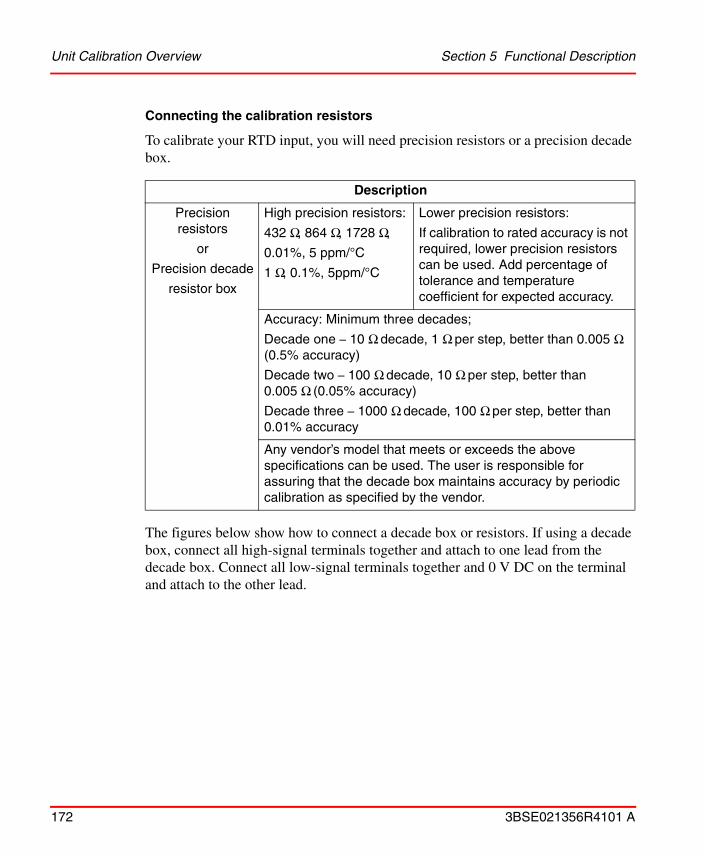
Unit Calibration Overview Section 5 Functional Description
172 3BSE021356R4101 A
Connecting the calibration resistors
To calibrate your RTD input, you will need precision resistors or a precision decade box.
The figures below show how to connect a decade box or resistors. If using a decade box, connect all high-signal terminals together and attach to one lead from the decade box. Connect all low-signal terminals together and 0 V DC on the terminal and attach to the other lead.
Description
Precision resistors
or
Precision decade
resistor box
High precision resistors:
432 Ω, 864 Ω, 1728 Ω,
0.01%, 5 ppm/°C
1 Ω, 0.1%, 5ppm/°C
Lower precision resistors:
If calibration to rated accuracy is not required, lower precision resistors can be used. Add percentage of tolerance and temperature coefficient for expected accuracy.
Accuracy: Minimum three decades;
Decade one – 10 Ω decade, 1 Ω per step, better than 0.005 Ω (0.5% accuracy)
Decade two – 100 Ω decade, 10 Ω per step, better than 0.005 Ω (0.05% accuracy)
Decade three – 1000 Ω decade, 100 Ω per step, better than 0.01% accuracy
Any vendor’s model that meets or exceeds the above specifications can be used. The user is responsible for assuring that the decade box maintains accuracy by periodic calibration as specified by the vendor.

Section 5 Functional Description Unit Calibration Overview
3BSE021356R4101 A 173
Figure 103. Connecting a decade box.
If using resistors, connect according to figure below.
Figure 104. Connecting resistors
0 1 2
Upper row
Middle row
Lower row
3 4 5 6 7 8 9 10 11 12 13 14 15
16 33
50 5134
0 V DC
High signals Low signals
Upper row
Middle row
Lower row
0 1 14 15
3016 17 31
5034 35 51
32 33

Unit Calibration Overview Section 5 Functional Description
174 3BSE021356R4101 A
Calibration resistor settings
At offset calibration the resistor value should always be set to 1 Ω. At gain calibration the resistor value should be according to the table below.
Type of RTDOffset calibration
value (Ideal counts)Gain calibration
100 Ω Pt. Euro (α(1)=0.00385)100 Ω Pt U.S. (α=0.003916)120 Ω Ni (α=0.00672)100 Ω Ni (α=0.00618)10 Ω Cu (α=0.00427)
(1) α=Temperature coefficient
1 Ω, 0.1%, 5 ppm/°C 432 Ω, 0.01%, 5 ppm/°C
200 Ω Pt. (α=0.00385)200 Ω Ni (α=0.00618)
1 Ω, 0.1%, 5 ppm/°C 864 Ω, 0.01%, 5 ppm/°C
500 Ω Pt. (α=0.00385) 1 Ω, 0.1%, 5 ppm/°C 1728 Ω, 0.01%, 5 ppm/°C

Section 5 Functional Description 200-IR8 Connections
3BSE021356R4101 A 175
200-IR8 Connections
Connect individual input wiring to numbered terminals as described in the table below. Always use shielded cables recommended by the RTD suppliers. 2-wire RTD cables are possible to connect but not recommended.
Figure 105. Wiring examples with 2- and 3-wire devices. Notice that not all terminal base units have three rows. This example shows connection to a 200-TB3.
16 21 22 27 29 3028
0 4 5 10 11 1312
5134
Upper row
Middle row
Lower row

200-IR8 Connections Section 5 Functional Description
176 3BSE021356R4101 A
Figure 106. Wiring examples with 2- and 3-wire devices connected to a 200-TB3T.
Screw terminal connections
200-TBN and 200-TBNF connections are not listed below since screw terminals 17–31 do not exist on these base terminal units.
Note. Lower row terminals 39–46 on 200-TB3T are for chassis ground connections.
To reduce susceptibility to noise, power analog units and discrete units from separate power supplies. Do not exceed a length of 10 m for DC power cabling.
Do not daisy chain power or ground from the RTD terminal base unit to any AC or DC discrete unit terminal base unit.
16 25 26 32 3331
0 8 9 1514
5134
Upper row
Middle row
Lower row
44 45 46

Section 5 Functional Description 200-IR8 Connections
3BSE021356R4101 A 177
Input200-TB2 & 200-TB3 200-TB3T
Terminals to be connected
Low signal 0 1 1
High signal 0 0 0
Signal Return 0 17 17
Shield Return 0 18 39
Low signal 1 3 3
High signal 1 2 2
Signal Return 1 19 19
Shield Return 1 20 40
Low signal 2 5 5
High signal 2 4 4
Signal Return 2 21 21
Shield Return 2 22 41
Low signal 3 7 7
High signal 3 6 6
Signal Return 3 23 23
Shield Return 3 24 42
Table continues on next page.

200-IR8 Connections Section 5 Functional Description
178 3BSE021356R4101 A
Input200-TB2 & 200-TB3 200-TB3T
Terminals to be connected
Low signal 4 9 9
High signal 4 8 8
Signal Return 4 25 25
Shield Return 4 26 43
Low signal 5 11 11
High signal 5 10 10
Signal Return 5 27 27
Shield Return 5 28 44
Low signal 6 13 13
High signal 6 12 12
Signal Return 6 29 29
Shield Return 6 30 45
Low signal 7 15 15
High signal 7 14 14
Signal Return 7 31 31
Shield Return 7 32 46
0 V DC 16, 33 16, 33
24 V DC 34, 51 34, 51

Section 5 Functional Description RTD Input Unit 200-IR8R
3BSE021356R4101 A 179
RTD Input Unit 200-IR8R200-IR8R is an I/O unit for eight 4-wire RTD input signals. The inputs have programmable filters and the unit is galvanically isolated. The unit has 16-bit resolution. One sensor type is supported.
Front Panel
1 = Insertable label for labelling individual input designations.2 = Power ON indicator.3 = Status indicators
Figure 107. RTD input unit 200-IR8R
200-IR8R can be used with the version B or later of Adapter 200-ANN.
1
32

Functional Description Section 5 Functional Description
180 3BSE021356R4101 A
Indicators
Sensor type
The following sensor type can be connected to 200-IR8R
Functional Description
The 8 analog input signals are connected to the unit via the screw terminal on the terminal base unit.
The inputs are arranged in a group of 8, galvanically isolated from the serial bus by optocouplers. It is possible to deselect unused channels to improve system throughput.
Power for the internal logic is provided via the process power supply.
Indication Function
Input Yellow LED, flashing when the input is sampled. Repetition of four flashes indicates an interrupt in the sensor connection and repetition of two flashes indicates a short-circuit in the sensor connection.
OK Green LED with the following functions:- continuous: when the unit is fully operational- flashing: critical fault condition- not lit: unit not powered
Sensor type α Temperature range
100 Ω Pt Euro 0.00385 -60 to +160°C
Since 200-IR8R does not receive power from the terminal base unit, 24 V DC must be applied to the unit before operation. If power is not applied, the unit position will appear to the adapter as an empty terminal base.

Section 5 Functional Description Functional Description
3BSE021356R4101 A 181
Figure 108. The 200-IR8R functional block diagram.
Filter and unit throughput
A programmable first notch filter in the analog-to-digital converter allows you to select a frequency for the first notch of the filter. Selection of the filter influences the analog-to-digital output data rate and changes the unit throughput.
First notch of filter (Hz) -3 dB frequency (Hz)
10 2.62
50 13.10
60 15.72
PW
DC/DC-converter
Voltage-reference
Bus
inte
rfac
e
A/D
-con
vert
er
Ana
log
Mul
tiple
xer
Optocoupler Channel 0
Channel
Channel
+24 V DC
0 V DC
Sense High Feed High
Feed Low
Sense Low

Functional Description Section 5 Functional Description
182 3BSE021356R4101 A
Figure 109. Filter response with first notch at 10 Hz.
Unit throughput means the time taken for a signal at the input terminal to arrive at the serial bus. It is a function of:
• the selected programmable first notch filter frequency,
• the number of channels actually configured for connection to a sensor.
A/D filter first notch frequencySystem throughput in ms
No. of channels scanned
10 Hz(16-bits)
50 Hz(16-bits)
60 Hz(16-bits)
1 632 150 130
2 1263 300 260
3 1895 450 390
4 2526 600 520
5 3158 750 650
6 3789 900 780
7 4421 1050 910
8 5052 1200 1040
Frequency – Hz
Gai
n –
dB

Section 5 Functional Description 200-IR8R Connections
3BSE021356R4101 A 183
200-IR8R Connections
Connect individual input wiring to numbered terminals as described in the figure and table below. Always use shielded cables recommended by the RTD supplier. The terminal base unit 200-TB3T must be used together with 200-IR8R.
Figure 110. Wiring example with a 4-wire device connected to the terminal base unit 200-TB3T.
C C N4 N7 CC
0 8 9 1514
VV
Upper row
Middle row
Lower row

200-IR8R Connections Section 5 Functional Description
184 3BSE021356R4101 A
Screw terminal connections
To reduce susceptibility to noise, supply analog units and discrete units from separate power supplies.
Input200-TB3T Input
200-TB3T Input
200-TB3T Input
200-TB3T
Terminal Terminal Terminal Terminal
Sense Low 0 0 Sense Low 2 4 Sense Low 4 8 Sense Low 6 12
Sense High 0 1 Sense High 2 5 Sense High 4 9 Sense High 6 13
Feed High 0 C Feed High 2 C Feed High 4 C Feed High 6 C
Feed Low 0 N0 Feed Low 2 N2 Feed Low 4 N4 Feed Low 6 N6
Sense Low 1 2 Sense Low 3 6 Sense Low 5 10 Sense Low 7 14
Sense High 1 3 Sense High 3 7 Sense High 5 11 Sense High 7 15
Feed High 1 C Feed High 3 C Feed High 5 C Feed High 7 C
Feed Low 1 N1 Feed Low 3 N3 Feed Low 5 N5 Feed Low 7 N7
Lower row terminals marked on 200-TB3T are for the cable shields and chassis ground connections.
Do not exceed a length of 10 m for DC power cabling..
Do not chain power or ground from the RTD terminal base unit to any discrete AC or DC unit terminal base unit.
M

Section 5 Functional Description Thermocouple Input Unit 200-IT8
3BSE021356R4101 A 185
Thermocouple Input Unit 200-IT8200-IT8 is an analog I/O unit for 8 thermocouple input signals. The inputs have programmable filters and the unit is galvanically isolated. The unit has 16 bit resolution. A high number of sensor types are supported. The unit comes with two Cold Junction Compensators (CJC).
1 = Holder for insertable label for individual output designations2 = Power ON indicator
Figure 111. Thermocouple input unit 200-IT8.
Front Panel
Indicators
Indication Function
OK Bi-colour (green/red) LED:
- Steady red at power up.
- Off while module performs diagnostic tests.
- If tests are passed, flashing green as long as configuration words are zero.
- Steady green when configured.
1
2

Sensor Types Section 5 Functional Description
186 3BSE021356R4101 A
Sensor Types
The following sensor types can be connected to 200-IT8:
Functional Description
The 8 input signals are connected to the unit via the screw terminal on the terminal base unit. They are galvanically isolated from the Serial bus (see function block diagram below).
It is possible to deselect unused channels to improve system throughput. Periodic user calibration is supported.
Power for the internal logic is provided via the process power supply.
Sensor type Range
millivolt ±76.5 mV
B +300 to +1800°C
E -270 to +1000°C
J -210 to +1200°C
K -270 to +1372°C
R -50 to +1768°C
S -50 to +1768°C
T -270 to +400°C
N -270 to +1300°C
C 0 to +2315°C
Since 200-IT8 does not receive power from the terminal base unit, 24 V DC must be applied to the unit before operation. If power is not applied, the unit position will appear to the adapter as an empty terminal base.
You can use a 200-TB2 or TB3 terminal base unit if you are using the thermocouple/mV unit in the millivolt mode only. You must use a 200-TB3T terminal base unit for all thermocouple uses to be able to connect the two cold junction sensors.

Section 5 Functional Description Filter and Unit Throughput
3BSE021356R4101 A 187
Figure 112. The 200-IT8 functional block diagram.
Numbers within parentheses in the diagram, refer to signal terminals on the terminal base unit, (e.g. 200-TB3) to which the unit is connected. Note that screw terminal numbers 35–50 only exist on 200-TB3. Terminals 17–32 do not exist on 200-TBN and 200-TBNF.
Filter and Unit Throughput
A programmable first notch filter (low pass filter) in the analog to digital converter lets you select a (cut-off) frequency for the first notch of the filter. Selection of the filter influences the analog to digital output data rate and changes the unit throughput. See below.
A fixed digital filter may be set by programming software. This filter settles to 100% of Full Scale input in 60 times the selected first notch filter time shown on next page.
Ser
ial b
us
Opto-coupler
Bus
inte
rfac
e
OK
DC/DC converter
A/D converter
Ana
log
Mul
tiple
xer
Channel 0
Channel 1
Channel 7
+24 V DC (34-51)
0 V DC (16-33)
Cold Junction Sensor
Cold Junction Sensor
Low signal (0)
High signal (1)
Shield Return (17)
Voltage reference

Filter and Unit Throughput Section 5 Functional Description
188 3BSE021356R4101 A
Figure 113. Filter response with first notch at 10 Hz.
Unit throughput means the time it takes for a signal at the input terminal to arrive at the serial bus. It is a function of:
• the selected programmable first notch filter (cut-off) frequency
• the number of channels actually configured for connection to a sensor
• the fixed digital filter
First notch of filter (Hz) -3 dB frequency (Hz)
10 2.62
25 6.55
50 13.10
60 15.72
100 26.20
250 65.50
500 131.00
1000 262.00
Frequency – Hz
Gai
n –
dB

Section 5 Functional Description Unit Calibration Overview
3BSE021356R4101 A 189
Unit Calibration Overview
Unit calibration is required to either improve the initial unit accuracy or to remove unit error due to component aging. In addition, calibration may be required to eliminate long lead wire resistance to open-circuit detection current.
200-IT8 is already calibrated at delivery. If calibration is required, the unit must be in an I/O system. Input channels can be calibrated in any order, or all at once.
To calibrate the unit:
1. Apply a reference to the desired input(s).
2. Start calibration.
Throughput
A/D filter first notch frequency
No. of channels scanned
10 Hz(16-bits)
25 Hz(16-bits)
50 Hz(16-bits)
60 Hz(16-bits)
100 Hz(16-bits)
250 Hz(13-bits)
500 Hz(13-bits)
1000 Hz(9-bits)
1 325 ms 145 ms 85 ms 75 ms 55 ms 37 ms 31 ms 28 ms
2 650 ms 290 ms 170 ms 150 ms 110 ms 74 ms 62 ms 56 ms
3 975 ms 435 ms 255 ms 225 ms 165 ms 111 ms 93 ms 84 ms
4 1.30 s 580 ms 300 ms 220 ms 148 ms 124 ms 124 ms 112 ms
5 1.625 s 725 ms 425 ms 375 ms 275 ms 185 ms 155 ms 140 ms
6 1.95 s 870 ms 510 ms 450 ms 330 ms 222 ms 186 ms 168 ms
7 2.275 s 1.015 s 595 ms 525 ms 385 ms 259 ms 217 ms 196 ms
8 2.60 s 1.16 s 680 ms 600 ms 440 ms 296 ms 248 ms 224 ms
To allow the internal unit temperature to stabilize, apply power to the unit for at least 40 minutes before calibrating.
Perform the offset calibration procedure first, and then the gain calibration procedure.

Unit Calibration Overview Section 5 Functional Description
190 3BSE021356R4101 A
Correction of the resistance error due to long lead wires is described in Removing lead wire or thermocouple extension wire resistance on page 192.
Connecting the calibration equipment
To calibrate your thermocouple input, you will need a precision voltage source or thermocouple simulator and calibration source.
The figures below show how to connect a precision voltage source. Connect all high signals together and attach to one lead from the precision voltage source. Connect all low signals together and 0 V DC on the terminal and attach to the other lead.
Figure 114. Connection of a precision voltage source.
For connection of Cold Junction Compensators (CJC), see figure below.
Description
Precision voltage source or thermocouple simulator and calibration source
0–100 mV, 1 µV resolution
Precision voltage source
Use 200-TB2 and 200-TB3 terminal base units for millivolt inputs only.CJC is not required if only millivolt inputs are used.
0 1 2
Upper row
Middle row
Lower row
3 4 5 6 7 8 9 10 11 12 13 14 15
C C
VV
0 V DC
High signals Low signals

Section 5 Functional Description Unit Calibration Overview
3BSE021356R4101 A 191
Figure 115. Connection of Cold Junction Compensators (CJC).
Precision voltage source
0 1 2
Upper row
Middle row
Lower row
3 4 5 6 7 8 9 10 11 12 13 14 15
C C
VV
CJCConnect to one of the terminals 0–7
C J C C J C
CJCConnect to one of the terminals 8–15

Unit Calibration Overview Section 5 Functional Description
192 3BSE021356R4101 A
Removing lead wire or thermocouple extension wire resistance
The thermocouple/mV unit has open circuit detection. This is accomplished by a 1 mA current source in the unit. This current flowing, through the lead wire or thermocouple extension wire, generates an error or offset voltage in the reading.
Calibrate this error out using one of the two following methods.
Method 1, Step 1
Figure 116. Calibrating error, method 1, step 1.
1. Disconnect all the lead wires at the terminal base unit.
2. Measure total loop resistance of both lead/extension wires and thermocouple.
3. If using a sensor other than a thermocouple, disconnect the lead wires at the sensor and tie together for this measurement. Reconnect after measurement.
4. After measuring, remove ohmmeter.
Ω
0 1 13 14 15
C C
V V
Upper row
Middle row
Lower row

Section 5 Functional Description Unit Calibration Overview
3BSE021356R4101 A 193
Method 1, step 2
Figure 117. Calibrating error, method 1, step 2.
1. Set decade box to value determined in step 1, and connect in series with a precision voltage source.
2. Connect to the input terminals of the particular channel you are calibrating.
3. Perform an offset and gain calibration according to software instructions.
4. Remove the precision voltage source.
5. Reconnect the lead wires to the input terminals for this channel.
6. Repeat this procedure for the remaining channels.
VoltageSource
DecadeBox
V V
Upper row
Middle row
Lower row
C
0 1 2 3 14 15
C
Disconnected

Unit Calibration Overview Section 5 Functional Description
194 3BSE021356R4101 A
Method 2
Figure 118. Calibrating error, method 2.
1. Disconnect the lead wire pair at the thermocouple or millivolt sensor.
2. Connect a precision voltage source across the lead wire pair.
3. Perform an offset and gain calibration according to software instructions.
4. Remove the precision voltage source.
5. Reconnect the lead wires to the input terminals for this channel.
6. Repeat this procedure for the remaining channels.
V V
Upper row
Middle row
Lower row
C
0 1 2 3 14 15
C
VoltageSource

Section 5 Functional Description 200-IT8 Connections
3BSE021356R4101 A 195
200-IT8 Connections
Connect individual input wiring to numbered terminals as described in the table below. Always use recommended compensation and shielded cables. The unit comes with 2 cold junction compensators (CJC) for use when using the thermocouple unit in the thermocouple mode. When using CJC the terminal base unit 200-TB3T must be used.
Figure 119. Example of millivolt input wiring to 200-TB3.
Connect the tail of the CJC to any of the associated thermocouple input terminals: 0–7 for CJC connected to 47, 48 and 49. The tail of the cold junction compensator shares a terminal with an input.
Connection to terminal base screw terminals
V V
Upper row
Middle row
Lower row
C C
0 1 2 3 14 15
N7 C
-
+

200-IT8 Connections Section 5 Functional Description
196 3BSE021356R4101 A
Figure 120. Example of 3-wire thermocouple wiring to 200-TB3T.
Screw terminal connections
To reduce susceptibility to noise, power analog units and discrete units from separate power supplies. Do not exceed a length of 10 m for DC power cabling.
Terminal base unit 200-TB3T is recommended with this unit.
Do not daisy chain power or ground from the RTD terminal base unit to any AC or DC discrete unit terminal base unit.
Connection to terminal base screw terminals
47 48 49 50
Upper row
Middle row
Lower row
C C
0 1 2 3 14 15
N7 C
36 37 38
-
+
CJCConnect toone of theterminals 0–7
39
CJCConnect toone of the terminals 8–15
1312
51

Section 5 Functional Description 200-IT8 Connections
3BSE021356R4101 A 197
Inputs200-TB2 & 200-TB3 200-TB3T
Terminals to be connected
High signal 0 0 0
Low signal 0 1 1
Shield Return 0 17 39
High signal 1 2 2
Low signal 1 3 3
Shield Return 1 19 40
High signal 2 4 4
Low signal 2 5 5
Shield Return 2 21 41
High signal 3 6 6
Low signal 3 7 7
Shield Return 3 23 42
High signal 4 8 8
Low signal 4 9 9
Shield Return 4 25 43
High signal 5 10 10
Low signal 5 11 11
Shield Return 5 27 44
High signal 6 12 12
Low signal 6 13 13
Shield Return 6 29 45
High signal 7 14 14
Low signal 7 15 15
Shield Return 7 31 46
0 V DC 16, 33 16, 33
24 V DC 34, 51 34, 51

AC Input Unit 200-IA8 Section 5 Functional Description
198 3BSE021356R4101 A
AC Input Unit 200-IA8200-IA8 is a digital I/O unit for eight 120 V AC input signals. The inputs are filtered and galvanically isolated.
1 = Holder for insertable label for individual input designations2 = Status indicators - show status of individual inputs.
Figure 121. AC input unit 200-IA8.
Front Panel
Indicators
Functional Description
The 8 AC input signals are connected to the unit via the screw terminals on the terminal base unit.
The inputs are galvanically isolated by optocouplers and the 8 inputs share a common AC voltage connection.
Indication Function
0–7 Yellow LED, lit when inputs are TRUE
1
2

Section 5 Functional Description Functional Description
3BSE021356R4101 A 199
The status of each input signal is indicated by a yellow LED on the front of the unit. Each signal is filtered by a low-pass filter.
The input signals are sampled at intervals determined by sample time. The signal status is changed only if two consecutive samples are the same. The sample time can be set by the programming software.
Power for the internal logic is provided via the adapter for the I/O system.
Figure 122. The 200-IA8 functional block diagram.
Numbers within parentheses in the diagram, refer to signal terminals on the terminal base unit, to which the unit is connected. (e.g. 200-TB3). Note that screw terminals 35–50 only exist on 200-TB3. Terminals 17–32 do not exist on 200-TBN and 200-TBNF.
Optocoupler
Channel 0120 V AC (34–51)
Channel 1
Channel 7
Inpu
t filt
er
Bus
inte
rface
Ser
ial b
us
Voltage V (1)
0 V AC (16–33)
Signal (0)
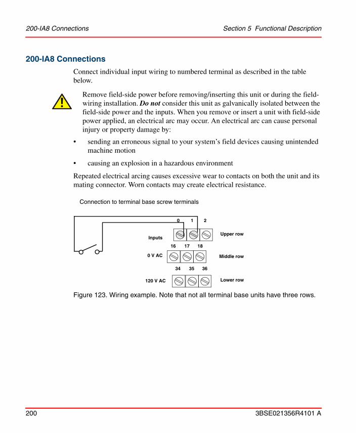
200-IA8 Connections Section 5 Functional Description
200 3BSE021356R4101 A
200-IA8 Connections
Connect individual input wiring to numbered terminal as described in the table below.
• sending an erroneous signal to your system’s field devices causing unintended machine motion
• causing an explosion in a hazardous environment
Repeated electrical arcing causes excessive wear to contacts on both the unit and its mating connector. Worn contacts may create electrical resistance.
Figure 123. Wiring example. Note that not all terminal base units have three rows.
Remove field-side power before removing/inserting this unit or during the field-wiring installation. Do not consider this unit as galvanically isolated between the field-side power and the inputs. When you remove or insert a unit with field-side power applied, an electrical arc may occur. An electrical arc can cause personal injury or property damage by:
Connection to terminal base screw terminals
Upper row
Middle row
Lower row
0 1 2
16 17 18
34 35 36
Inputs
120 V AC
0 V AC

Section 5 Functional Description 200-IA8 Connections
3BSE021356R4101 A 201
Screw terminal connections
Input
200-TB2 & 200-TB3 200-TBN & 200-TBNF
Terminals to be connected
Signal (upper row)
120 V AC(upper row)
Signal 120 V AC
0 0 1 0 1
1 2 3 2 3
2 4 5 4 5
3 6 7 6 7
4 8 9 8 9
5 10 11 10 11
6 12 13 12 13
7 14 15 14 15
0 V AC 16–33(middle row)
16, 33
120 V AC 34–51(lower row)
34, 51

AC Output Unit 200-OA8 Section 5 Functional Description
202 3BSE021356R4101 A
AC Output Unit 200-OA8200-OA8 is a digital I/O unit for eight 120 V AC output signals. The unit is galvanically isolated by optocouplers.
1 = Holder for insertable label for individual output designations2 = Status indicators – show status of individual outputs.
Figure 124. AC output unit 200-OA8.
Front Panel
Indicators
Functional Description
The 8 AC output signals are connected to the unit via the screw terminals on the terminal base unit.
The outputs are galvanically isolated by optocouplers and the 8 outputs share a common 0 V AC connection.
The status of each output signal is indicated by a yellow LED on the front of the unit. Output indicators do not work if 120 V AC is missing.
Indication Function
0–7 Yellow LED, lit when outputs are TRUE
1
2

Section 5 Functional Description Functional Description
3BSE021356R4101 A 203
Power for the internal logic is provided via the adapter for the I/O system.
Figure 125. The 200-OA8 functional block diagram.
Numbers within parentheses in the diagram, refer to signal terminals on the terminal base unit, to which the unit is connected (e.g. 200-TB3). Note that screw terminals 35–50 only exist on 200-TB3. Terminals 17–32 do not exist on 200-TBN and 200-TBNF.
Optocouplers
120 V AC (34–51)
Channel 0
Channel 1
Channel 7
Bus
inte
rface
Ser
ial b
us
Voltage V (0)
0 V AC (0)
0 V AC (16–33)

200-OA8 Connections Section 5 Functional Description
204 3BSE021356R4101 A
200-OA8 Connections
Connect individual output wiring to numbered terminal as described in the table below.
• sending an erroneous signal to your system’s field devices causing unintended machine motion
• causing an explosion in a hazardous environment
Repeated electrical arcing causes excessive wear to contacts on both the unit and its mating connector. Worn contacts may create electrical resistance.
Figure 126. Wiring example. Note that not all terminal base units have three rows.
Remove field-side power before removing/inserting this unit or during the field-wiring installation. Do not consider this unit as galvanically isolated between the field-side power and the outputs. When you remove or insert a unit with field-side power applied, an electrical arc may occur. An electrical arc can cause personal injury or property damage by:
Connection to terminal base screw terminals
Upper row
Middle row
Lower row
0 1 2
16 17 18
34 35 36
Outputs
120 V AC
0 V AC

Section 5 Functional Description 200-OA8 Connections
3BSE021356R4101 A 205
Screw terminal connections
Output
200-TB2 & 200-TB3 200-TBN & 200-TBNF
Terminals to be connected
Signal (upper row)
0 V AC(upper row)
Signal 0 V AC
0 0 1 0 1
1 2 3 2 3
2 4 5 4 5
3 6 7 6 7
4 8 9 8 9
5 10 11 10 11
6 12 13 12 13
7 14 15 14 15
0 V AC 16–33 (middle row)
16, 33
120 V AC 34–51(lower row)
34, 51

AC Input Unit 200-IM8 Section 5 Functional Description
206 3BSE021356R4101 A
AC Input Unit 200-IM8200-IM8 is a digital I/O unit for eight 230V AC input signals. The inputs are filtered and galvanically isolated.
1 = Holder for insertable label for individual input designations2 = Status indicators - show status of individual inputs.
Figure 127. AC input unit 200-IM8.
Front Panel
Indicators
Functional Description
The 8 AC input signals are connected to the unit via the screw terminals on the terminal base unit.
The inputs are galvanically isolated by optocouplers and the 8 inputs share a common AC voltage connection.
The status of each input signal is indicated by a yellow LED on the front of the unit.
Indication Function
0–7 Yellow LED, lit when inputs are TRUE
1
2

Section 5 Functional Description Functional Description
3BSE021356R4101 A 207
Each signal is filtered by a digital low-pass filter. The filter has one common time constant for the inputs 0–7. The sum of the hardware and digital filter time constants affects the shortest possible pulse length which can be detected. The delay times are given in the table below (at 2 MHz clock frequency from the serial I/O bus). The delay time is set in the programming software.
Power for the internal logic is provided via the adapter for the I/O system.
Delay Time for Inputs 0–7Maximum Delay Time
Off to ON On to Off
Delay Time 0 (default) 7.5 ms 26.5 ms
Delay Time 1 8 ms 27 ms
Delay Time 2 9 ms 28 ms
Delay Time 3 10 ms 29 ms
Delay Time 4 12 ms 31 ms
Delay Time 5 16 ms 35 ms
Delay Time 6 24.5 ms 44 ms
Delay Time 7 42 ms 60.5 ms

200-IM8 Connections Section 5 Functional Description
208 3BSE021356R4101 A
Figure 128. The 200-IM8 functional block diagram.
200-IM8 Connections
Terminal base unit 200-TBN must be used together with 200-IM8.
Connect individual input wiring to numbered terminal as described in the table below.
• sending an erroneous signal to your system’s field devices causing unintended machine motion
• causing an explosion in a hazardous environment
Repeated electrical arcing causes excessive wear to contacts on both the unit and its mating connector. Worn contacts may create electrical resistance.
Remove field-side power before removing/inserting this unit or during the field-wiring installation. When you remove or insert a unit with field-side power applied, an electrical arc may occur. An electrical arc can cause personal injury or property damage by:
Optocoupler
Channel 0 34
Channel 1
Channel 7
Bus
inte
rfac
e
Ser
ial I
/O b
us
0
I/O unit Terminal base unit
2
51
14
1633

Section 5 Functional Description 200-IM8 Connections
3BSE021356R4101 A 209
Figure 129. Wiring example.
Screw terminal connections
Total current drawn through the terminal base unit is limited to 10 A, refer to Connecting the Power Supply Cables on page 31.
Input200-TBN
Signal 230 V AC(1)
(1) 1, 3, 5, 7, 9, 11, 13 and 15 are internally connected to 230 V AC in the I/O unit.
0 0 1
1 2 3
2 4 5
3 6 7
4 8 9
5 10 11
6 12 13
7 14 15
0 V AC 16, 33
230 V AC 34, 51
Connection to terminal base screw terminals
Upper row
Lower row
0 2 4
34 1 3
Inputs
230 V AC
16

AC Output Unit 200-OM8 Section 5 Functional Description
210 3BSE021356R4101 A
AC Output Unit 200-OM8200-OM8 is a digital I/O unit for eight 230 V AC output signals. The unit is galvanically isolated by optocouplers.
1 = Holder for insertable label for individual input designations2 = Status indicators - show status of individual outputs.
Figure 130. AC output unit 200-OM8.
Front Panel
Indicators
Functional Description
The 8 AC output signals are connected to the unit via the screw terminals on the terminal base unit.
The outputs are galvanically isolated by optocouplers and the 8 outputs share a common 0 V AC connection.
The status of each output signal is indicated by a yellow LED on the front of the unit. Output indicators do not work if 230 V AC is not connected.
Power for the internal logic is provided via the adapter for the I/O system.
Indication Function
0–7 Yellow LED, lit when outputs are TRUE
1
2
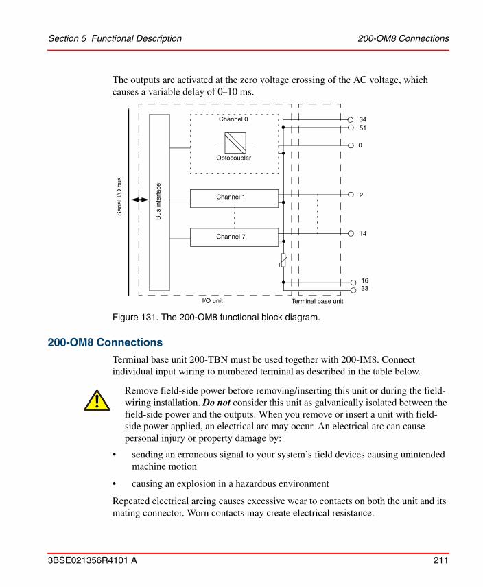
Section 5 Functional Description 200-OM8 Connections
3BSE021356R4101 A 211
The outputs are activated at the zero voltage crossing of the AC voltage, which causes a variable delay of 0–10 ms.
Figure 131. The 200-OM8 functional block diagram.
200-OM8 Connections
Terminal base unit 200-TBN must be used together with 200-IM8. Connect individual input wiring to numbered terminal as described in the table below.
• sending an erroneous signal to your system’s field devices causing unintended machine motion
• causing an explosion in a hazardous environment
Repeated electrical arcing causes excessive wear to contacts on both the unit and its mating connector. Worn contacts may create electrical resistance.
Remove field-side power before removing/inserting this unit or during the field-wiring installation. Do not consider this unit as galvanically isolated between the field-side power and the outputs. When you remove or insert a unit with field-side power applied, an electrical arc may occur. An electrical arc can cause personal injury or property damage by:
Optocoupler
Channel 0 34
Channel 1
Channel 7
Bus
inte
rfac
e
Ser
ial I
/O b
us
0
I/O unit Terminal base unit
2
51
14
1633

200-OM8 Connections Section 5 Functional Description
212 3BSE021356R4101 A
Figure 132. Wiring example. Connection to terminal base screw terminals.
Screw terminal connections
Total current drawn through the terminal base unit is limited to 10 A, refer to Connecting the Power Supply Cables on page 31.
It is not possible to connect the outputs in parallel.
Output200-TBN
Signal Power Terminal(1)
(1) 1, 3, 5, 7, 9, 11, 13 and 15 are internally connected to 0 V AC in the I/O unit.
0 0 1
1 2 3
2 4 5
3 6 7
4 8 9
5 10 11
6 12 13
7 14 15
0 V AC 16, 33
230 V AC 34, 51
Upper row
Lower row
0 2 4
34 1 3
Outputs
Power Terminal
16
(0 V AC)

Section 5 Functional Description Relay Output Unit 200-OW8
3BSE021356R4101 A 213
Relay Output Unit 200-OW8200-OW8 is an I/O unit for 8 relay output signals. The outputs are galvanically isolated.
1 = Holder for insertable label for individual output designations2 = Status indicators - show status of individual outputs.
Figure 133. Relay output unit 200-OW8.
Front Panel
Indicators
Functional Description
The 8 relay output signals are connected to the unit via the screw terminals on the terminal base unit.
If voltage >132 V terminal base unit 200-TBN or 200-TBNF must be used.
Relay voltage is provided via an external power supply.
Indication Function
0–7 Yellow LED, lit when outputs are TRUE
1
2

Functional Description Section 5 Functional Description
214 3BSE021356R4101 A
Figure 134. The 200-OW8 functional block diagram.
Representative examples of various relay load contacts. 34, 16, 1, 0, etc. in the diagram, refer to signal terminals on the terminal base unit, to which the unit is connected. (e.g. 200-TB3). Note that screw terminals 35–50 only exist on 200-TB3. Terminals 17–32 do not exist on 200-TBN and 200-TBNF.
Channel 0
Channel 1
Channel 7
24 V DC (34)
(0)
(1)
0 V DC (16)
Bus
inte
rfac
e
Ser
ial b
us

Section 5 Functional Description 200-OW8 Connections
3BSE021356R4101 A 215
200-OW8 Connections
Connect individual output wiring to numbered terminal as described in the table below.
Figure 135. Two wiring examples. Connection to terminal base screw terminals. Note that not all terminal base units have three rows.
Do not attempt to increase load current or wattage capability load beyond the maximum rating by connecting two or more outputs in parallel. The slightest variation in relay switching time may cause one relay to momentarily switch the total load current.
If inductive loads are connected, use a diode across each load. Do not use Zener diodes.
Do not connect a signal with tension on. The leakage current from the transient suppressions can be hazardous.
Upper row
Middle row
Lower row
0 1 2
16 17 18
34 35 36
24 V DC
0 V DC
+ DC or AC
- DC or AC

200-OW8 Connections Section 5 Functional Description
216 3BSE021356R4101 A
Screw terminal connections
Output
200-TB2 & 200-TB3 200-TBN & 200-TBNF
Terminals to be connected
Signal
0 0 0
1 1
1 2 2
3 3
2 4 4
5 5
3 6 6
7 7
4 8 8
9 9
5 10 10
11 11
6 12 12
13 13
7 14 14
15 15
0 V DC 16–33 16, 33
24 V DC 34–51 34, 51

Section 5 Functional Description Short-circuit Proof Output Unit 200-OB8EP
3BSE021356R4101 A 217
Short-circuit Proof Output Unit 200-OB8EP200-OB8EP is a short circuit proof output unit for eight signals. The unit is intended for detection of short circuit condition in its output circuit or low impedance loads causing excessive current draw. Each of the eight output channels has a current sensing circuit. The unit is designed to allow up to 2.0 A current per channel.
1 = Holder for insertable label for individual output designation2 = Status indicators3 = Reset button
Figure 136. Short-circuit proof output unit 200-OB8EP.
Front Panel
Indicators
This unit requires a great current consumption and must be properly powered.
Indication Function
Output 0–7 Yellow LED, lit when outputs are TRUE
Fault 0–7 Red LED, when lit indicating fault
1
2
3

Functional Description Section 5 Functional Description
218 3BSE021356R4101 A
Functional Description
The outputs are galvanically isolated by optocouplers and the 8 outputs share a common ground connection. The unit is connected via the terminal base unit.
Process side load levels are detected by 200-OB8EP. The unit is designed to source a surge current of approximately 4.0 A for 10 ms without indicating a fault. The unit does not distinguish between an overcurrent condition and a short circuit condition.
Resetting a unit fault
Faults can be reset in three ways:
• Press the fault reset button.
• Toggle the reset bit associated with the output.1
• Cycle the 24 V DC supply to the unit.
The reset function resets all output fault bits simultaneously.
Using the fault reset button
When pressing the manual reset button:
1. the fault indicator for the faulted output turns off for about 500 ms (the faulted output will not attempt to turn on during this delay).
2. after the 500 ms delay, the faulted output attempts to turn on.
3. if the external condition causing the fault is corrected, the output will remain on, the fault indicator is off, and the status indicator is on.
1. A 3 second delay is recommended in the reset program.

Section 5 Functional Description Functional Description
3BSE021356R4101 A 219
Figure 137. The 200-OB8EP functional block diagram.
Numbers within parentheses in the diagram, refer to signal terminals on the terminal base unit, to which the unit is connected (e.g. 200-TB3). Note that screw terminals 35–50 only exist on 200-TB3. Terminals 17–32 do not exist on 200-TBN and 200-TBNF.
Bus
inte
rfac
e
Ser
ial b
us
Fault
ResetReset fault
Fault latches and fault LED circuitry
FET-driveand overloaddetect
Output circuitsN-FET
Channel 0
Channel 1
Channel 7
24 V DC
0 V DCOutput (0)
Power + 5 V DC

200-OB8EP Connections Section 5 Functional Description
220 3BSE021356R4101 A
200-OB8EP Connections
Connect individual output wiring to numbered terminals as described in the table below.
Figure 138. Wiring example. Connection to terminal base screw terminals. Note that not all terminal base units have three rows.
Screw terminal connections
Output channel
200-TB2 & 200-TB3 200-TBN & 200-TBNF
Terminals to be connected
Output terminal(upper row)
0 V DC(upper row)
0 V DC(middle row)
Output terminal
0 V DC
0 0 1 17 0 1
1 2 3 19 2 3
2 4 5 21 4 5
3 6 7 23 6 7
4 8 9 25 8 9
5 10 11 27 10 11
6 12 13 29 12 13
7 14 15 31 14 15
0 V DC 16–33 (middle row)
16, 33
24 V DC 34–51(lower row)
34, 51
Upper row
Middle row
Lower row
0 1 2
16 17 18
34 35 36
Outputs
24 V DC
0 V DC

Section 5 Functional Description Dummy Unit 200-DUTB
3BSE021356R4101 A 221
Dummy Unit 200-DUTB200-DUTB is a dummy unit used to occupy empty locations on terminal base units of the I/O system. It protects the I/O system from external mechanical and electrical damage.
Figure 139. Dummy unit 200-DUTB.

Adapter for Central I/O System 200-ANN Section 5 Functional Description
222 3BSE021356R4101 A
Adapter for Central I/O System 200-ANNThis unit is a central I/O adapter unit, intended for connection of up to eight terminal base units equipped with I/O units. 200-ANN connects the Advant Controller 250 or the SoftController to the central I/O system.
Figure 140. Adapter for central I/O system 200-ANN.
Front Panel
Indicator and component identification
Unit 200-ANN version A must not be connected to the Advant Controller 250 or the SoftController.
1 Green LED (Power indicator), lit when internal 5 V DC is present.
2 Green LED (Comm indicator), lit when 200-ANN is initiated by the Controller unit.
3 Connection to previous adapter or BPN via the controller bus.
4 Locking tab for DIN rail mounting.
1
2
3
5
6
4
7

Section 5 Functional Description Functional Description
3BSE021356R4101 A 223
Functional Description
The central I/O Adapter unit passes on data from the Controller unit to the I/O system and vice versa. It also connects adjacent adapters in a central I/O system.
The power for this unit is taken from the system bus and is indicated on the left hand Power LED on the front panel. This unit supplies all I/O units internally with power supply.
The status of the adapter is indicated by the right hand Comm LED on the front panel. It is lit when 200-ANN is initiated by the Controller unit.
Figure 141. The 200-ANN functional block diagram
5 Connection to next adapter or BPT start.
6 Male I/O bus connector
7 Slot for connection to an adjacent terminal base unit
Comm
+5 V DCPower
PWR
NN
bus
Inte
rface
Ser
ial b
usIn
terfa
ceNN
bus
Ser
al b
us
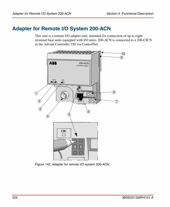
Adapter for Remote I/O System 200-ACN Section 5 Functional Description
224 3BSE021356R4101 A
Adapter for Remote I/O System 200-ACNThis unit is a remote I/O adapter unit, intended for connection of up to eight terminal base units equipped with I/O units. 200-ACN is connected to a 200-CICN in the Advant Controller 250 via ControlNet.
Figure 142. Adapter for remote I/O system 200-ACN.
1
2
3
45
6
8
9
7
10

Section 5 Functional Description Front Panel
3BSE021356R4101 A 225
Front Panel
Indicators and component identification
1 Red/Green LED, Communication indicator A
2 Red/Green LED, Communication indicator B
3 Red/Green LED, Adapter status indicator
4 ControlNet cable BNC connector
5 ControlNet node selection push button switches
6 ControlNet programming terminal connector (for future use)
7 +24 V DC connection terminals
8 0 V DC connection terminals
9 Male I/O bus connector
10 Slot for connection to an adjacent terminal base unit

Functional Description Section 5 Functional Description
226 3BSE021356R4101 A
Functional Description
The remote I/O Adapter unit pass on data from the controller to the remote I/O system and vice versa. 200-ACN is connected to the ControlNet.
The power for this unit is taken from a 24 V DC supply. The status of the adapter is indicated by the LEDs on the front panel. The unit also supports the I/O units with internal current.
Figure 143. The 200-ACN functional block diagram
Comm
+5 V DCPower
+24 V DC
Con
trol
Net
inte
rfac
e
Ser
ial I
/O b
us
inte
rface
Con
trol
Net
Ser
ial
I/O b
us
OK
1 MΩ

Section 5 Functional Description LED Indications
3BSE021356R4101 A 227
LED Indications
LEDs A and B (Comm) simultaneously
LEDs A & B Indication
Off No power or reset
Red Adapter inoperative
Red-Green (flashing alternately)
Adapter self test
Red-Off (flashing alternately)
Bad node configuration (i.e. duplicate node addresses)
LED A (Comm) individually (B is OFF)
Off Channel disabled
Green Channel operational
Flashing Green-Off Temporary network errors
Flashing Red-Off Cable fault or lonely node. Broken cable, redundancy warning, etc.
Flashing Red-Green Bad network configuration
OK indicator
Off Channel disabled
Flashing Green On-line but not connected
Green On-line, link okay, connected
Flashing Red Recoverable fault
Red Critical, adapter failure

Node Address Selection Section 5 Functional Description
228 3BSE021356R4101 A
Node Address Selection
A node address in the range 2–99 should be selected for the 200-ACNs. It is highly recommended to select addresses in a consecutive manner to minimize network load.
Screw terminals
The screw terminals are located on the lower right part of the front. The two terminals located on the upper row are for 0 V DC and the two on the lower row are for 24 V DC.
0 V DC
24 V DC
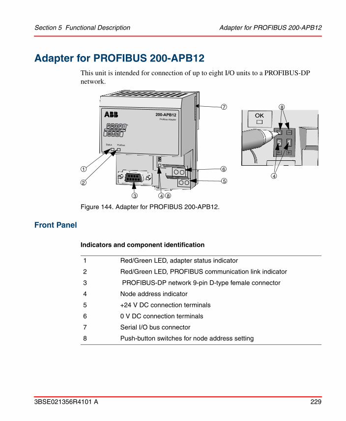
Section 5 Functional Description Adapter for PROFIBUS 200-APB12
3BSE021356R4101 A 229
Adapter for PROFIBUS 200-APB12This unit is intended for connection of up to eight I/O units to a PROFIBUS-DP network.
Figure 144. Adapter for PROFIBUS 200-APB12.
Front Panel
Indicators and component identification
1 Red/Green LED, adapter status indicator
2 Red/Green LED, PROFIBUS communication link indicator
3 PROFIBUS-DP network 9-pin D-type female connector
4 Node address indicator
5 +24 V DC connection terminals
6 0 V DC connection terminals
7 Serial I/O bus connector
8 Push-button switches for node address setting
1
2
4
6
7
45
3
8
8

Functional Description Section 5 Functional Description
230 3BSE021356R4101 A
Functional Description
The 200-APB12 adapter acts as a slave device to a DP master controller on the PROFIBUS network and transfers data between the controller and the I/O units. For information on PROFIBUS-DP installation, see “Installation Guidelines for PROFIBUS-DP/FMS” (available from ABB Automation, order code PB-IGE).
The power is taken from a 24 V DC supply. The status of the adapter is indicated by the LEDs on the front panel. The unit also supports I/O units with internal current via the serial I/O bus.
LED Indications
Node Address Selection
A node address in the range 1–99 should be selected for the 200-APB12. A GSD file for the configuration can be ordered from ABB Automation.
Adapter Status Indicator
Off No power
Steady green Normal operation
Flashing red/off Recoverable fault- Faulty I/O unit- Incorrect I/O unit installed- Node address changed since power-up
Steady red Unrecoverable fault
PROFIBUS Communication Link Indicator
Off No power or no communication
Steady green Data are being transmitted and received
Flashing red/off Recoverable fault- Invalid Send parameter data- Invalid Check configuration data
Steady red Unrecoverable fault, unable to communicate

Section 5 Functional Description Screw Terminals
3BSE021356R4101 A 231
Screw Terminals
The screw terminals are located on the lower right side of the front of the unit. The two terminals located on the upper row are for 0 V DC and the two on the lower row are for +24 V DC.
Figure 145. The 200-APB12 functional block diagram
STATUS
+5 V DCPower
+24 V DC
PR
OF
IBU
Sin
terf
ace
Ser
ial b
usin
terf
ace
PR
OF
IBU
S
Ser
ial I
/O b
us
PROFIBUS

Adapter for Serial I/O Bus 200-AIO Section 5 Functional Description
232 3BSE021356R4101 A
Adapter for Serial I/O Bus 200-AIO
Figure 146. Adapter for Serial I/O bus 200-AIO.
The adapter is used to connect up to 8 I/O units of type S200 I/O or S200L I/O to AC 800C or SoftController via a serial I/O bus cable available in three different lengths, see TK210V005, TK210V010 and TK210V025 on page 235. The adapter has a female connector for the cable and a male connector for the serial I/O bus of the attached I/O unit.
The adapter has no indications, and the screw terminals are not used.

Section 5 Functional Description Power Supply for the Remote I/O System 200-PS1.3
3BSE021356R4101 A 233
Power Supply for the Remote I/O System 200-PS1.3Power supply 200-PS1.3 supplies the remote I/O system with power.
Figure 147. Power supply for the remote I/O system 200-PS1.3.
Front Panel
Indicator and component identification
1 Green LED (Power indicator), lit when internal 24V DC is present.
2 Screw terminal for AC protective earth (GR)
3 Screw terminal for connection to 0 V AC (L2/N)
4 Screw terminal for connection to 120/230 V AC (L1)
5 Screw terminals used to pass 120/230 V AC power to adjacent 200-PS1.3 supplies
6 Locking tab for DIN rail mounting.
7 Screw terminal for connection to 0 V DC (COM)
8 Screw terminal for connection to 24 V DC (24 V)
1
2
3
7
4
5
86

Functional Description Section 5 Functional Description
234 3BSE021356R4101 A
Functional Description
Power supply 200-PS1.3 supplies the remote I/O system with power.
The power for this unit is taken from a main voltage outlet and the status of the output voltage is indicated on the Power LED on the front panel. This unit provides sufficient 24 V DC power to supply 4 adapter units.
If the output current exceeds 1.5 A, then the power supply will be switched off. The output voltage is restored by removing the overload and then switching off and on the power supply.
LED indication (Power)
Figure 148. The 200-PS1.3 functional block diagram
The LED is not lit No power applied to power supply oroutput voltage exceeds 35 V DC and overvoltage protection has shut the unit downor output current is below 0.1 Aor output current is above 1.0 A
The 200-PS1.3 power supply provides sufficient 24 V DC power to operate up to 4 adapter units. Do not attempt to operate an entire I/O system with this power supply.
85–265 V AC
Power
24 V DC

Section 5 Functional Description I/O System Accessories
3BSE021356R4101 A 235
I/O System Accessories
Cables
200-CE1 and 200-CE3
Extension cables for the I/O system. These cables are used when one I/O system is split into two adjacent I/O rows. 200-CE1 connects two I/O rows. Cable length for 200-CE1 is 300 mm and for 200-CE3 900 mm.
TK210V005, TK210V010 and TK210V025
Serial I/O bus cable for connecting I/O units of type S200 I/O or S200L I/O to AC 800C or SoftController. The bus cable is available in three different lengths. Cable length for TK210V005 is 0.5 m, for TK201V010 is 1 m and for TK210V025 is 2.5 m.
Mounting Profiles
Profile for vertical or horizontal mounting of the I/O system and when using the CE1 cable. A locking plate and a screw are included with the mounting profiles.
MP990
Profile length 990 mm.
MP890
Profile length 890 mm.
MP590
Profile length 590 mm.
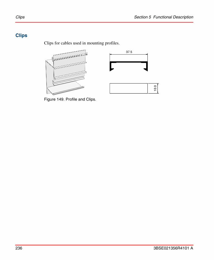
Clips Section 5 Functional Description
236 3BSE021356R4101 A
Clips
Clips for cables used in mounting profiles.
Figure 149. Profile and Clips.

3BSE021356R4101 A 237
Section 6 Maintenance and Service
This section describes the maintenance required by the I/O system and how to troubleshoot it.
Replacing I/O System UnitsYou can remove and insert I/O system units except adapters and terminal base units under system power, however to avoid hazardous conditions we recommend to switch off the process side power before removing or inserting an I/O unit. When you remove or insert a unit under power, you may cause an electric arc. An electric arc is hazardous because it may:
• send an erroneous signal to your process devices causing unintended machine motion.
• cause an explosion of e.g. due to the nature of the surrounding gases.
Repeated electric arcing causes excessive wear to the contacts on both the unit and its mating connector in the terminal base. Worn contacts may create electrical resistance.
Each unit has a mechanical code key which matches a corresponding key on the terminal base unit. This prevents units of different types from being interchanged in such a manner that electrical damage occurs. For information on how to replace units, see Removing a Terminal Base Unit on page 48.
Read the Safety Summary on page 17, before performing operations which may be dangerous to personnel or cause damage to equipment.

Changing Fuses Section 6 Maintenance and Service
238 3BSE021356R4101 A
Changing FusesWhen changing fuses, please do not use metal objects inside the units. This could cause damage and electrostatic discharge. We also highly recommend that you wear an ESD bracelet.
Changing fuses in 200-TBNF
There are eight fuses located above the upper row of screw terminals, which protects even numbered inputs 0-14. Press the fuse holder down toward the terminal strip. Remove the faulty fuse from the fuse holder. Replace the fuse holder by rotating the fuse holder back to vertical until it snaps into the locked position.
The type of fuse is described in Terminal Base Unit 200-TBNF on page 268.
Figure 150. Changing fuses in 200-TBNF.
Before changing fuses, turn process side power off.
Fuse

Section 6 Maintenance and Service Troubleshooting the I/O System
3BSE021356R4101 A 239
Troubleshooting the I/O System
General
Input levels are in accordance with to the IEC 1131-2 standard. In the transition region the LED indicators and status read by the system are not defined.
Troubleshooting 200-PS1.3
Troubleshooting 200-IB16
System is running and the adapter active.
Symptom Measure
Power LED is OFF 1. Check input power.
2. Cycle power to the unit.
3. Check for output short-circuit.
4. Replace the unit.
Symptom Measure
LED status on an input is ON and the control system is in status OFForif the LED status on an input is OFF and the control system’s status is on
1. Check that the input is not forced.
2. Check that the input voltage is not within the transition region.
3. Replace the unit.
LED OFF despite +24 V DC on the input screw terminal
Replace unit and/or terminal base unit.

Troubleshooting 200-OB16 or 200-OB16P Section 6 Maintenance and Service
240 3BSE021356R4101 A
Troubleshooting 200-OB16 or 200-OB16P
System is running and the adapter is active. The output is activated.
Symptom Measure
LED status on the output is ON. No +24 V DC on the output screw terminal
1. Check if the output has been short-circuited to 0 V DC.- No short-circuit/overcurrent: Replace the unit and/or the terminal base unit. OK.- Short-circuit. Go to step 2.
2. Release the cable from the screw terminal and check if the cable is short-circuited to 0 V DC. - Short-circuit: check the cabling. Correct failures. OK.- No short-circuit. Go to step 3.
3. Release the unit and check if the output screw terminal is short-circuited to 0 V DC. - Short-circuit: replace the terminal base unit. - No short-circuit: replace the output unit.
LED status on the output is OFF and +24 V DC on the output screw terminal
Replace the unit.
LED status on the output is OFF and +24 V DC is NOT measured on the output screw terminal
1. Check that the output is not forced to OFF.
2. Check that +24 V DC is fed to the terminal base unit. +24 V DC: replace the unit and/or the terminal base unit. 0 V DC: check the cabling.

Section 6 Maintenance and Service Troubleshooting 200-IB10xOB6
3BSE021356R4101 A 241
System is running and the adapter is active. The output is not activated.
Troubleshooting 200-IB10xOB6
See Troubleshooting 200-IB16 on page 239 for inputs and Troubleshooting 200-OB16 or 200-OB16P on page 240 for outputs.
Troubleshooting 200-IB32
System is running and the adapter active.
Symptom Measure
LED status on the output is ON and +24 V DC on the output screw terminal
1. Check that the output is not forced to ON status.
2. Replace the unit.
LED Status on the output is OFF and +24 V DC on the output screw terminal
Loosen the cable attached to the output screw terminal and check the voltage level. +24 V DC: Replace unit and/or the terminal base unit. 0 V DC: Check the cables.
Symptom Measure
LED status on an input is ON and the control system is in status OFForLED status on an input is OFF and the control system’s status is on
1. Check that the input is not forced.
2. Check that the input voltage is not within the transition region.
3. Replace the unit.
LED OFF despite +24 V DC on the input screw terminal
Replace unit and/or terminal base unit.

Troubleshooting 200-OB32P Section 6 Maintenance and Service
242 3BSE021356R4101 A
Troubleshooting 200-OB32P
System is running and the adapter is active. The output is activated.
Symptom Measure
LED status on the output is ON. No +24 V DC on the output screw terminal
1. Check if the output has been short-circuited to 0 V DC.- No short-circuit/overcurrent: Replace the unit and/or the terminal base unit. OK.- Short-circuit. Go to step 2.
2. Release the cable from the screw terminal and check if the cable is short-circuited to 0 V DC. - Short-circuit: check the cabling. Correct failures. OK.- No short-circuit. Go to step 3.
3. Release the unit and check if the output screw terminal is short-circuited to 0 V DC. - Short-circuit: replace the terminal base unit. - No short-circuit: replace the output unit.
LED status on the output is OFF and +24 V DC on the output screw terminal
Replace the unit.
LED status on the output is OFF and +24 V DC is NOT measured on the output screw terminal
1. Check that the output is not forced to OFF.
2. Check that +24 V DC is fed to the terminal base unit. +24 V DC: replace the unit and/or the terminal base unit. 0 V DC: check the cabling.

Section 6 Maintenance and Service Troubleshooting 200-IB16xOB16P
3BSE021356R4101 A 243
System is running and the adapter is active. The output is not activated.
Troubleshooting 200-IB16xOB16P
See Troubleshooting 200-IB32 on page 241 for inputs and Troubleshooting 200-OB32P on page 242 for outputs.
Troubleshooting 200-IP2
The system is in operation.
Symptom Measure
LED status on the output is ON and +24 V DC on the output screw terminal
1. Check that the output is not forced to ON status.
2. Replace the unit.
LED Status on the output is OFF and +24 V DC on the output screw terminal
Loosen the cable attached to the output screw terminal and check the voltage level. +24 V DC: Replace unit and/or the terminal base unit. 0 V DC: Check the cables.
Symptom Action
All the LEDs are off 1. Check the power supply(12–24 V DC ±10%)
2. Replace 200-IP2
The red LED remains on longer than 2 seconds
Initialization error, replace 200-IP2
The yellow LED on inputs A, B, Z or G is not lit
1. Check the polarity of the input signal +/-
2. Check the input signal voltage (6–26.4 V DC)
3. Replace 200-IP2

Troubleshooting 200-IP4 Section 6 Maintenance and Service
244 3BSE021356R4101 A
Troubleshooting 200-IP4
The system is in operation.
Symptom Action
All the LEDs are off 1. Check the power supply (12–24 V DC ±10%)
2. Replace 200-IP4
The red LED remains on longer than 2 seconds
Initialization error, replace 200-IP4
The yellow LED on inputs N or D is not lit
1. Check the polarity of the input signal +/-
2. Check the input signal voltage (6–26.4 V DC)
3. Replace 200-IP4

Section 6 Maintenance and Service Troubleshooting 200-IE8
3BSE021356R4101 A 245
Troubleshooting 200-IE8
System is running and the adapter active.
Symptom Measure
PWR LED is not lit 1. Check 24 V DC
2. Check wiring for 24 V DC
3. Replace the unit.
A break in a 4–20 mA loop is detected by the system
1. Check cabling and connections.
2. Check the sensor.
3. Check the value at the terminal base unit.(1)
4. Check that the correct type of input is selected in the hardware configuration editor.
5. Replace the unit.
(1) Use a voltmeter that has ≥ 10 MΩ input resistance to measure the voltage where you have a known high-precision resistance. The current can be measured in series with the current loop. It is recommended that a Zener diode be placed in series with the loop. Note that the current input for a 200-IE8 has a resistance (which can be considered as a precision resistance) of 238 Ω (I=U/238).
An erroneous analog value has been detected by the system
1. Check if a power-line filter for the power supply is has been fitted.
2. Check if shielded twisted-pair cables are connected for the I/O signals.
3. Check the value at the terminal base unit with a voltmeter that has ≥ 10 MOhm input resistance(1).
4. Check that the correct type of input is selected in the hardware configuration program.
5. Replace the unit.
There is no signal at the terminal base unit
1. Check cabling and connections.
2. Check that input is within range.
3. Check the sensor.
4. Replace terminal base unit.

Troubleshooting 200-OE4 Section 6 Maintenance and Service
246 3BSE021356R4101 A
Troubleshooting 200-OE4
The output is activated.
Troubleshooting 200-IE4xOE2
See Troubleshooting 200-IE8 on page 245 for inputs and Troubleshooting 200-OE4 on page 246 for outputs.
Symptom Measure
PWR LED is not lit 1. Check +24 V DC.
2. Check the wiring to +24 V DC.
A break in a 4–20 mA loop has been detected by the system
1. Check cabling and connections.
2. Check if a power-line filter for the power supply has been fitted.
3. Check if shielded twisted-pair cables have been connected for the I/O signals.
4. Check the actuator.
5. Check the value at the terminal base unit.(1)
6. Check that the correct type of output is selected in the hardware configuration program.
7. Replace the unit.
(1) Use a voltmeterwith ≥ 10 MΩ input resistance to measure the voltage where you have a known high-precision resistance. The current can be measured in series with the current loop. It is recommended that a Zener diode be placed in series with the loop. Note that the minimum load of the current outputs is 15 Ω.
An erroneous analog value has occurred at the actuator
1. Check value at the terminal base unit(1).
2. Check that the correct type of output is selected in the hardware configuration program.
3. Replace the unit.
There is no signal at the terminal base unit.
1. Check cabling and connections.
2. Check the actuator.
3. Replace the terminal base unit.

Section 6 Maintenance and Service Troubleshooting 200-IF4I
3BSE021356R4101 A 247
Troubleshooting 200-IF4I
System is running and the adapter active.
Symptom Measure
OK LED is not lit Replace the unit.
OK LED is solid red 1. Check communication with the system.
2. Replace the unit.
OK LED is flashing green
1. Check the 24 V DC.
2. Check the wiring for 24 V DC.
3. Check that the I/O unit has been configured.
A break in a 4–20 mA loop is detected by the system
1. Check cabling and connections.
2. Check the sensor.
3. Check the value at the terminal base unit.(1)
4. Check that the correct type of input is selected in the hardware configuration editor.
5. Replace the unit.
(1) Use a voltmeter with ≥ 10 MΩ input resistance to measure the voltage where you have a known high-precision resistance. The current can be measured in series with the current loop. It is recommended that a Zener diode be placed in series with the loop. The current input for a 200-IF4I has a resistance of approximately 100 Ω (the input resistance will increase to 10 kΩ if the 24 V DC is removed).
An erroneous analog value has been detected by the system
1. Check if a power-line filter for the power supply has been fitted.
2. Check if shielded twisted-pair cables have been used for the I/O signals.
3. Check the value at the terminal base unit with a voltmeter with ≥ 10 MOhm input resistance(1).
4. Check that the correct type of input is selected in the hardware configuration program.
5. Replace the unit.
There is no signal at the terminal base unit
1. Check cabling and connections.
2. Check that input is within range.
3. Check the sensor.
4. Replace terminal base unit.

Troubleshooting 200-OF4I Section 6 Maintenance and Service
248 3BSE021356R4101 A
Troubleshooting 200-OF4I
The output is activated.
Symptom Measure
PWR LED is not lit 1. Check +24 V DC.
2. Check the wiring to +24 V DC.
OK LED is not lit 1. Check 24 V DC.
2. Check wiring for 24 V DC.
3. Replace the unit.
OK LED is solid red 1. Indicating a critical failure.
2. No contact with the controller or the controller is not running (watchdog time-out).
3. Replace the unit.
OK LED is flashing green
1. The unit is not configured or a field power fault.
2. Configure the unit or check the field power.
A break in a 4–20 mA loop has been detected by the system
1. Check cabling and connections.
2. Check if a power-line filter for the power supply has been fitted.
3. Check if shielded twisted-pair cables have been connected for the I/O signals.
4. Check the actuator.
5. Check the value at the terminal base unit.(1)
6. Check that the correct type of output is selected in the hardware configuration program.
7. Replace the unit.
An erroneous analog value has occurred at the actuator
1. Check value at the terminal base unit(1).
2. Check that the correct type of output is selected in the hardware configuration program.
3. Replace the unit.

Section 6 Maintenance and Service Troubleshooting 200-IR8
3BSE021356R4101 A 249
Troubleshooting 200-IR8
System is running and the adapter active.
The LED OK indicates the general status of 200-IR8 and the status in relation to communication with the application in the controller.
There is no signal at the terminal base unit.
1. Check cabling and connections.
2. Check the actuator.
3. Replace the terminal base unit.
(1) Use a voltmeter that has ≥ 10 MΩ input resistance to measure the voltage where you have a known high-precision resistance. The current can be measured in series with the current loop. It is recommended that a Zener diode be placed in series with the loop.
Symptom Measure
Steady red: Indicating a critical fault Replace the unit.
Flashing red: Indicating a noncritical fault (such as open sensor, input out of range, etc.)
1. Check cabling and connectors.
2. Check that correct type is selected in the hardware configuration.
3. Replace the unit.
Flashing green: Indicating that the unit is functional but not configured
1. Start the program to configure the unit.
2. Check the program.
3. Replace the unit.
Symptom Measure

Troubleshooting 200-IR8R Section 6 Maintenance and Service
250 3BSE021356R4101 A
Troubleshooting 200-IR8R
System is running and the adapter active.
The LED OK indicates the general status of 200-IR8R and the status in relation to communication with the application in the controller.
Troubleshooting 200-IT8
System is running and the adapter active.
The LED OK indicates the general status of 200-IT8 and the status in relation to communication with the application in the controller.
Symptom Measure
OK LED is flashing green (indicating a critical failure)
Replace the unit.
OK LED is steady green but all input LEDs are not lit (indicating that no input is configured)
1. Check the program.
2. Replace the unit.
An input LED is flashing repeatedly 4 times (indicating an interrupt in the sensor connection)
1. Check cabling and connectors
2. Replace the unit.
An input LED is flashing repeatedly twice (indicating a short-circuit in the sensor connection)
1. Check cabling and connectors
2. Replace the unit.
Symptom Measure
Steady red: Indicating a critical fault
Replace the unit.
Flashing red: Indicating a noncritical fault (such as open sensor, input out of range etc)
1. Check cabling and connectors.
2. Check that correct type is selected in the hardware configuration.
3. Replace the unit.
Flashing green: Indicating that the unit is functional but not configured
1. Start the program to configure the unit.
2. Check the program.
3. Replace the unit.

Section 6 Maintenance and Service Troubleshooting 200-IM8
3BSE021356R4101 A 251
Troubleshooting 200-IM8
System is running and the adapter active.
Troubleshooting 200-OM8
System is running and the adapter active. The output is activated.
This I/O unit is using a high-voltage supply for the inputs.
Symptom Measure
LED status on an input is ON and the control system is in status OFF orif the LED status on an input is OFF and the control system’s status is on.
1. Check that the input is not forced.
2. Check that the input voltage is not within the transition region.
3. Replace the unit.
LED OFF despite 230 V AC on the input screw terminal.
Replace unit and/or terminal base unit.
This I/O unit is using a high-voltage supply for the inputs.
Symptom Measure
LED status on the output is ON and there is no 230 V AC on the output screw terminal
1. Check 230 V AC supply:230 V AC: replace the unit.0 V AC: check the cables.
2. Replace the unit.
LED status on the output is OFF and there is 230 V AC on the output screw terminalorLED status on an output is OFF and there is no 230 V AC on the output screw terminal
1. Check that the output is not forced to OFF
2. Check 230 V AC supply:230 V AC: replace the unit.0 V AC: check the cables.
LED OFF despite 230 V AC on the output screw terminal.
Replace unit and/or terminal base unit.

Troubleshooting 200-IA8 Section 6 Maintenance and Service
252 3BSE021356R4101 A
Troubleshooting 200-IA8
System is running and the adapter active.
This I/O unit is using a high-voltage supply for the inputs.
Symptom Measure
LED status on an input is ON and the control system is in status OFF orif the LED status on an input is OFF and the control system’s status is ON
1. Check that the input is not forced.
2. Check that the input voltage is not within the transition region.
3. Replace the unit.
LED OFF despite 120 V AC on the input screw terminal
Replace unit and/or terminal base unit.

Section 6 Maintenance and Service Troubleshooting 200-OA8
3BSE021356R4101 A 253
Troubleshooting 200-OA8
System is running and the adapter active. The output is activated
System is running and the adapter is active. The output is not activated.
This I/O unit is using a high-voltage supply for the inputs.
Symptom Measure
LED status on the output is ON and there is no 120 V AC on the output screw terminal
1. If TBNF terminal base is used, then check the fuse (it is recommended to analyse the reason to the blown fuse before it is replaced). The fuse is not a foolproof protection for the I/O unit. It may be necessary to replace the unit.
2. Check 120 V AC supply. If the supply is not OK, analyse the reason.
3. Replace the unit and/or the terminal base unit.
LED status on the output is OFF and there is no 120 V AC on the output screw terminals
1. Check that the output is not forced to OFF.
2. Replace the unit.
LED status on the output is OFF but there is 120 V AC on the output screw terminal
Replace unit and/or terminal base unit.
Symptom Measure
LED status on the output is ON and there is 120 V AC on the output screw terminal
1. Check that the output is not forced to ON.
2. Replace the unit.
LED Status on the output is OFF and there is 120 V AC on the output screw terminal.
1. Check for erroneous current path that holds the output to a high potential (120 V AC).
2. Replace the unit and/or the terminal base unit.

Troubleshooting 200-OW8 Section 6 Maintenance and Service
254 3BSE021356R4101 A
Troubleshooting 200-OW8
System is running and the adapter is active. The output is activated.
System is running and the adapter is active. The output is not activated.
Symptom Measure
LED status on the output is ON and the output relay is not active
Check +24 V DC supply to the terminal base unit.+24V DC: Replace the I/O unit and/or the terminal base unit0 V DC: Check the cables
LED status on the output is OFF and the output relay is not active
1. Check that the output is not forced to OFF
2. Check +24 V DC supply to the terminal base unit+24V DC: replace the I/O unit and/or the terminal base unit0 V DC: check the cables
LED status on the output is OFF and the output relay is active
Replace the unit.
Symptom Measure
LED status on the output is ON and the output relay is active
1. Check that the output is not forced to ON
2. Replace the unit
LED status on the output is OFF and the output relay is active
Replace the unit

Section 6 Maintenance and Service Troubleshooting 200-OB8EP
3BSE021356R4101 A 255
Troubleshooting 200-OB8EP
System is running and the adapter is active. The output is activated.
System is running and the adapter is active. The output is not activated.
Symptom Measure
LED status on the output is ON. No +24 V DC on the output screw terminal
Replace the output unit.
LED status on the output is OFF and +24 V DC on the output screw terminal
Replace the unit.
LED status on the output is OFF and no +24 V DC on the output screw terminal
1. Check that the output is not forced to OFF.
2. Check that +24 V DC is fed to the terminal base unit. +24 V DC: replace the unit and/or the terminal base unit. 0 V DC: check the cabling.
Symptom Measure
LED status on the output is ON and +24 V DC on the output screw terminal
1. Check that the output is not forced to ON status.
2. Replace the unit.
LED Status on the output is OFF and +24 V DC on the output screw terminal
Loosen the cable attached to the output screw terminal. Check the voltage level on the output screw terminal. +24 VDC: replace unit and/or the terminal base unit. 0 V DC: check the cables.
The fault indicator does not turn off when pressing the manual reset button
Replace the unit.

Troubleshooting 200-ANN Section 6 Maintenance and Service
256 3BSE021356R4101 A
Troubleshooting 200-ANN
In order to determine if an error is present in the central I/O system, start checking the connected adapter(s), 200-ANN (in table below only called ANN).
1. First check that all connectors are properly inserted. If so, the ANN ”Power” LED is immediately lit at power up.
2. The ANN ”Comm” LED is lit a few seconds after power up (flashing a few times during power up).
If you are going to replace a cable or unit, always switch off the power before replacement.
Symptom Measure
The ”Power” LEDs of all connected ANNs are not lit but the Controller unit ”Power” LED is lit
1. Check the cable CBA.
2. Replace the ANN no. 0.
The ”Power” LEDs are lit on one or more ANNs closest to the controller and the remaining ANNs ”Power” LEDs are not lit
1. Check the cable CAA leading to the first unit with its ”Power” LED not lit.
2. Replace the first unit with its ”Power” LED not lit. If this action is not successful replace the ANN with the original unit.
3. Replace the last ANN with its ”Power” LED lit.
The ”Power” LED on one ANN is not lit and this ANN is followed by another with its ”Power” LED lit
Replace the unit.
The ”Comm” LEDs of all connected ANNs are not lit and the Controller unit indicates ”STOP”
See “Troubleshooting of the controller”.
The ”Comm” LEDs of all connected ANNs are not lit and the Controller unit does not indicate ”STOP”
1. Check the cable CBA.
2. Replace the ANN no. 0.

Section 6 Maintenance and Service Troubleshooting 200-ACN
3BSE021356R4101 A 257
Troubleshooting 200-ACN
OK status LED – indicates general ACN and I/O unit status.
The ”Comm” LEDs are lit on one or more ANNs closest to the controller and the remaining ANN ”Comm” LEDs are not lit
1. Check the cable CAA leading to the first adapter with its ”Comm” LED not lit.
2. Replace the first ANN with its ”Comm” LED not lit. If this action is not successful replace ANN with the original unit.
2. Replace the last ANN with its ”Comm” LED lit.
The ”Comm” LED on one ANN is not lit and this adapter is followed by an ANN with its ”Comm” LED lit
Replace the adapter.
Symptom Measure
Off: No power or ACN in ”reset” state 1. Check 24 V DC power to ACN
2. Replace ACN
Flashing green: ACN is active, but there is no exchange of I/O-data between the controller and the ACN
1. Check controller: Is it switched on? Are there any control program running? Is the CICN unit operating and connected to the cable system?
2. Check ACN node address – set correctly according to the hardware configuration in the control program.
3. Check application program – is the hardware configuration correct (the ACN-address)?
Steady green: The ACN unit is active and communicates with the controller
Symptom Measure

Troubleshooting 200-ACN Section 6 Maintenance and Service
258 3BSE021356R4101 A
LEDs Comm A and B simultaneously – indicate status related to start-up of the ACN unit, or serious network errors.
Flashing red: Erroneous configuration 1. Check the I/O units–are they installed according to the configuration that was defined in the application program?
2. Check the ACN node address–has it been changed without resetting (power down, power-up) the unit?
Steady red: Unit failure Replace ACN.
Symptom Measure
Off: No power or ACN in ”reset” state 1. Check 24 V DC power to ACN
2. Replace ACN
Flashing red-green: ACN self test is running
Wait for a couple of seconds until self-test is terminated
Flashing red: There are other node(s) that uses the same node address as this ACNNodes on the network do not have the same network parameters
Check node address (the node address must be unique on this network). Network parameter error; will be corrected automatically by the CICN node.
Steady red: Unit failure Replace ACN.
Symptom Measure

Section 6 Maintenance and Service Troubleshooting 200-APB12
3BSE021356R4101 A 259
LED Com A (B disabled) – indicates status related to the network
Troubleshooting 200-APB12
STATUS LED – indicates APB12 and I/O unit status.
Symptom Measure
Off: Channel disabled 1. Check 24 V DC power to ACN
2. Replace ACN
Steady green: Channel operates normally
Flashing green-off: Temporary network error (some messages are lost)The network functions are not configured
1. Check node addresses. Note that there must be a CICN with node address 1(1).
2. Check the cable system. (trunk cable, taps, terminators, connectors etc.)
(1) The CICN configures the network parameters in all nodes on the network.
Flashing red-off: ACN is lonely node. Possible reasons:- Cable system fault- No other nodes active on the network
1. Check ACN is connected to network.
2. If this ACN is the only node on the network then switch on other nodes. Also make sure that there is a CICN with node address 1 connected.
3. Check that the cable system is OK. Look for broken cable, faulty connectors or taps etc.
4. Replace ACN.
Steady red: Unit failure Replace ACN.
Symptom Measure
Off: No power 1. Check 24 V DC power to APB12.
2. Replace APB12.
Flashing red/off: Recoverable fault. APB12 is active, but there is no exchange of I/O-data between the DP master controller and the APB12
1. Check APB12 node address – has it changed since power-up?
2. Check application program – is the hardware configuration correct (the correct I/O units installed)?
3. Are any of the attached I/O units faulty?

Troubleshooting 200-APB12 Section 6 Maintenance and Service
260 3BSE021356R4101 A
PROFIBUS LED – indicates communication link status.
Steady red: Unit failure Replace APB12.
Steady green: Normal operation
Symptom Measure
Off: No power or no communication
1. Check 24 V DC power to APB12.
2. Check that APB12 is connected to the network, that there is no broken cable, faulty connectors or taps.
3. Check that there is a DP master controller switched on, connected to the network, and with the control program running.
4. Replace APB12.
Steady green: Data are being transmitted or received
Flashing red/off: Recoverable fault- Invalid Send parameter message received- Invalid Check configuration message received
1. Check the network for intermittent disturbances.
2. Check node address (the node address must be unique on the network).
3. Check the DP master slave configuration.
Steady red: Unrecoverable fault, unable to communicate
Replace APB12.
Symptom Measure

3BSE021356R4101 A 261
Appendix A Technical Specifications
General Specifications
Technical Data
Power supply 24 V DC (19.2–30 V DC) incl. 5% ripple according to EN 61131-2 standard i.e. +20%, –15% and max 5% ripple
Environmental conditions
Industrial
Protection rating IP20
Vibration 0.15 mm/2g to 150 Hz, 3*30 min, type test according to IEC 68-2-6
Packaged volume for the I/O system units
1 unit:W 133 x H 133 x D 93 mm (1.65 dm3)≤ 10 units:W 470 x H 278x D 150 mm (19.60 dm3)
Approvals (when product or packaging is marked)
CE marked and meets EMC directive 89/336/EEC according to EN 50081-2 and EN 50082-2
Low-Voltage Directive 73/23/EEC with supplement 93/68/EEC according to the following standard: EN 61131-2 (only applicable for units connected to 50–1000 V AC and/or 75–1500 V DC)
UL listed according to UL 508 as open equipment
The technical data for hazardous locations is described individually for each unit

Terminal Base Unit 200-TB2 Appendix A Technical Specifications
262 3BSE021356R4101 A
Terminal Base Unit 200-TB2
Technical Data
Number of terminals
1 row of 161 row of 181 row of 2
Current capacity 10 A max.
Voltage rating 132 V AC max (rms).
Isolation voltage Channel-to-channel isolation determined by inserted unit
Temperature Operating: 0 °C to + 55 °CNon-operating: -40 °C to + 85°C
Humidity 5–95%, non-condensing
Approvals (when product or packaging is marked)
CSA certified; class I div. 2 hazardous locations, group A, B, C, D, temperature code T6
European Ex certified, class I, zone 2, group II C
Backplane key code
Determined by inserted unit
Wire size Solid or stranded copper wire 0.5–2.5 mm2 orAWG 20–AWG 12
Weight 0.225 kg excl. package0.320 kg incl. package
Dimensions W 94 x H 94 x D 58 mm (with an I/O unit inserted: 72 mm)
Order code 200-TB2

Appendix A Technical Specifications Terminal Base Unit 200-TB3
3BSE021356R4101 A 263
Terminal Base Unit 200-TB3
Technical Data
Number of terminals 1 row of 16 2 rows of 18
Current capacity 10 A max.
Voltage rating 132 V AC max (rms).
Isolation voltage Channel-to-channel isolation determined by inserted unit
Temperature Operating: 0 °C to + 55 °CNon-operating: -40 °C to + 85°C
Humidity 5–95%, non-condensing
Approvals (when product or packaging is marked)
CSA certified; class I div. 2 hazardous locations, group A, B, C, D, temperature code T6
European Ex certified, class I, zone 2, group II C
Backplane key code Determined by inserted unit
Wire size Solid or stranded copper wire 0.5–2.5 mm2 orAWG 20–AWG 12
Weight 0.225 kg excl. package0.320 kg incl. package
Dimensions W 94 x H 94 x D 58 mm (with an I/O unit inserted: 72 mm)
Order code 200-TB3

Terminal Base Unit 200-TB3S Appendix A Technical Specifications
264 3BSE021356R4101 A
Terminal Base Unit 200-TB3S
Technical Data
Number of terminals
1 row of 16 2 rows of 18
Current capacity 10 A max.
Voltage rating 132 V AC max (rms).
Isolation voltage Channel-to-channel isolation determined by inserted unit
Temperature Operating: 0 °C to + 55 °CNon-operating: -40 °C to + 85°C
Humidity 5–95%, non-condensing
Approvals (when product or packaging is marked)
CSA certified; class I div. 2 hazardous locations, group A, B, C, D, temperature code T6
European Ex certified, class I, zone 2, group II C
Backplane key code
Determined by inserted unit
Wire size Solid or stranded copper wire 0.5–2.5 mm2 orAWG 20–AWG 12
Weight 0.225 kg excl. package0.320 kg incl. package
Dimensions W 94 x H 94 x D 58 mm (with an I/O unit inserted: 72 mm)
Order code 200-TB3S
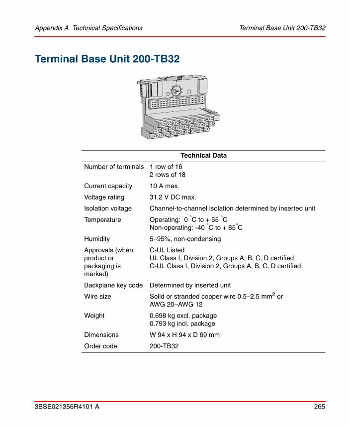
Appendix A Technical Specifications Terminal Base Unit 200-TB32
3BSE021356R4101 A 265
Terminal Base Unit 200-TB32
Technical Data
Number of terminals 1 row of 16 2 rows of 18
Current capacity 10 A max.
Voltage rating 31.2 V DC max.
Isolation voltage Channel-to-channel isolation determined by inserted unit
Temperature Operating: 0 °C to + 55 °CNon-operating: -40 °C to + 85°C
Humidity 5–95%, non-condensing
Approvals (when product or packaging is marked)
C-UL ListedUL Class I, Division 2, Groups A, B, C, D certifiedC-UL Class I, Division 2, Groups A, B, C, D certified
Backplane key code Determined by inserted unit
Wire size Solid or stranded copper wire 0.5–2.5 mm2 orAWG 20–AWG 12
Weight 0.698 kg excl. package0.793 kg incl. package
Dimensions W 94 x H 94 x D 69 mm
Order code 200-TB32

Terminal Base Unit 200-TB3T Appendix A Technical Specifications
266 3BSE021356R4101 A
Terminal Base Unit 200-TB3T
Technical Data
Number of terminals
1 row of 162 rows of 18
Current capacity 10 A max.
Voltage rating 132 V AC max (rms).
Isolation voltage Channel-to-channel isolation determined by inserted unit
Temperature Operating: 0 °C to + 55 °CNon-operating: -40 °C to + 85°C
Humidity 5–95%, non-condensing
Approvals (when product or packaging is marked)
CSA certified; class I div. 2 hazardous locations, group A, B, C, D, temperature code T6
European Ex certified, class I, zone 2, group II C
Backplane key code
Determined by inserted unit
Wire size Solid or stranded copper wire 0.5–2.5 mm2 orAWG 20–AWG 12
Weight 0.225 kg excl. package0.320 kg incl. package
Dimensions W 94 x H 94 x D 58 mm (with an I/O unit inserted: 72 mm)
Order code 200-TB3T

Appendix A Technical Specifications Terminal Base Unit 200-TBN
3BSE021356R4101 A 267
Terminal Base Unit 200-TBN
Technical Data
Number of terminals 2 rows of 10
Current capacity 10 A max.
Voltage rating 264 V AC max. (rms)
Isolation voltage Channel-to-channel isolation determined by inserted unit
Temperature Operating: 0 °C to + 55 °CNon-operating: -40 °C to + 85°C
Humidity 5–95%, non-condensing
Approvals (when product or packaging is marked)
CSA certified; class I div. 2 hazardous locations, group A, B, C, D, temperature code T6
European Ex certified, class I, zone 2, group II C
Backplane key code Determined by inserted unit
Wire size Solid or stranded copper wire 0.5–2.5 mm2 orAWG 20–AWG 12
Weight 0.175 kg excl. package0.270 kg incl. package
Dimensions W 94 x H 94 x D 48 mm (with an I/O unit inserted: 72 mm)
Order code 200-TBN

Terminal Base Unit 200-TBNF Appendix A Technical Specifications
268 3BSE021356R4101 A
Terminal Base Unit 200-TBNF
Technical Data
Number of terminals 2 rows of 10
Current capacity 10 A max.
Voltage rating 264 V AC max. (rms)
Fuses 8 (5x20 mm)
Isolation voltage Channel-to-channel isolation determined by inserted unit
Temperature Operating: 0 °C to +55 °CNon-operating: –40 °C to +85°C
Humidity 5–95%, non-condensing
Approvals (when product or packaging is marked)
CSA certified.
Backplane key code Determined by inserted unit
Wire size Solid or stranded copper wire 0.5–2.5 mm2 orAWG 20–AWG 12
Weight 0.175 kg excl. package0.270 kg incl. package
Dimensions W 97 x H 94 x D 48 mm (with an I/O unit inserted: 72 mm)
Order code 200-TBNF

Appendix A Technical Specifications Digital Input Unit 200-IB16
3BSE021356R4101 A 269
Digital Input Unit 200-IB16
Technical Data
Number of inputs 16 positive logic
Counter input 16-bit(1) on channel 15, 500 Hz max. Min. pulse width 1 ms
Galvanic isolation Yes (via optocouplers)
Status indicators 16 yellow LEDs for input indications
ON-state input voltage 10.0 V DC min., 24 V DC nominal, 31.2 V DC max.
ON-state input current 2.0 mA min., 8.0 mA nominal at 24V DC, 12.0 mA max.
OFF-state input voltage 5.0 V DC max.
OFF-state input current Current must be ≤ 1.5 mA to be defined as being in OFF state.
Filter time Software programmable
Filter First order low-pass filter with time constant 5µs
Input impedance 4.6 kOhms max.
Isolation voltage 100% tested at 850 V DC for 1 s between user and system. No isolation between individual channels
Internal current consumption (from the serial bus)
30 mA max.
Power dissipation 6.1 W at 31.2 V DC max.
Temperature (see derating curve below)
Operating: 0 °C to +55 °CNon-operating: –40 °C to +85°C

Digital Input Unit 200-IB16 Appendix A Technical Specifications
270 3BSE021356R4101 A
Humidity 5–95%, non-condensing
Approvals (when product or packaging is marked)
CSA certified; class I div. 2 hazardous locations, group A, B, C, D, temperature code T3C
European Ex certified, class I, zone 2, group II C
Unit identity 0281 (hex)
Backplane key code 2
Weight 0.085 kg excl. package0.180 kg incl. package
Dimensions W 94 x H 46 x D 53 mm
Order code 200-IB16
(1) Only article No. 490-1760-59 or later. Older versions have a 5-bit counter (article No. 490-1760-43) or none (article No. 490-1760-05, -26)
Technical Data
0°C 10°C 20°C 30°C 40°C 50°C55°C
10
15
20
25
27.528.5
3031.2
Ambient temperature
The area within the curve represents the safe operating range for the unit under various conditions of 24 V DC input voltage and ambient temperatures. The filled part in the upper right corner is included in the safe operating range if normal mounting, but not valid if the units are mounted vertically.
Derating curve
On
stat
e in
put v
olta
ge V
DC

Appendix A Technical Specifications Digital Output Unit 200-OB16
3BSE021356R4101 A 271
Digital Output Unit 200-OB16
Technical Data
Number of Outputs 16 positive logic
Galvanic isolation Yes (via optocouplers)
Status indicators 16 yellow LEDs for output indications
ON-state voltage range 10 V DC min.24 V DC nominal31.2 V DC max.
Output current rating 8 A (16 outputs at 0.5 A)
ON-state current 1.0 mA min. per channel450 mA max. per channel when in parallel500 mA max. per channel
OFF-state voltage 5 V DC max. (if load resistance max. 10 kΩ)31.2 V DC max. (if no load connected)
Surge current 2 A for 50 ms, repeatable every 2 seconds
OFF-state leakage current
0.5 mA max.
ON-state voltage drop 0.5 V DC max.
Isolation voltage 100% tested at 850V DC for 1s between plant and system. No isolation between individual channels
Output Signal DelayOFF to ONON to OFF
0.5 ms max.1.0 ms max.

Digital Output Unit 200-OB16 Appendix A Technical Specifications
272 3BSE021356R4101 A
Internal current consumption (from the serial bus)
80 mA max.
Power dissipation 5.3 W at 31.2 V DC max.
Temperature Operating: 0 °C to +55 °CNon-operating: –40 °C to +85°C
Humidity 5–95%, non-condensing
Approvals (when product or packaging is marked)
CSA certified; class I div. 2 hazardous locations, group A, B, C, D, temperature code T4A
European Ex certified, class I, zone 2, group II C
Unit identity 0191 (hex)
Backplane key code 2
External DC powerSupply voltageSupply current
24 V DC nominal (19.2–31.2 V DC)49 mA at 24 V DC (38 mA–65 mA)
Weight 0.085 kg excl. package0.180 kg incl. package
Dimensions W 94 x H 46 x D 53 mm
Fuse 800 mA (when used in TBNF)
Order code 200-OB16
Technical Data
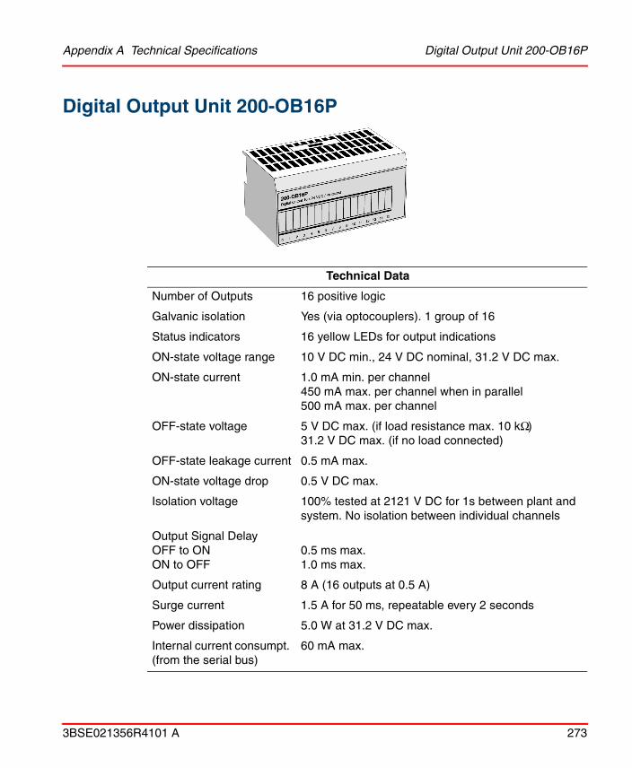
Appendix A Technical Specifications Digital Output Unit 200-OB16P
3BSE021356R4101 A 273
Digital Output Unit 200-OB16P
Technical Data
Number of Outputs 16 positive logic
Galvanic isolation Yes (via optocouplers). 1 group of 16
Status indicators 16 yellow LEDs for output indications
ON-state voltage range 10 V DC min., 24 V DC nominal, 31.2 V DC max.
ON-state current 1.0 mA min. per channel450 mA max. per channel when in parallel500 mA max. per channel
OFF-state voltage 5 V DC max. (if load resistance max. 10 kΩ)31.2 V DC max. (if no load connected)
OFF-state leakage current 0.5 mA max.
ON-state voltage drop 0.5 V DC max.
Isolation voltage 100% tested at 2121 V DC for 1s between plant and system. No isolation between individual channels
Output Signal DelayOFF to ONON to OFF
0.5 ms max.1.0 ms max.
Output current rating 8 A (16 outputs at 0.5 A)
Surge current 1.5 A for 50 ms, repeatable every 2 seconds
Power dissipation 5.0 W at 31.2 V DC max.
Internal current consumpt. (from the serial bus)
60 mA max.

Digital Output Unit 200-OB16P Appendix A Technical Specifications
274 3BSE021356R4101 A
Temperature (see derating curve on next page)
Operating: 0 °C to +55 °CNon-operating: –40 °C to +85°C
Humidity 5–95%, non-condensing
Approvals (when product or packaging is marked)
CSA certified; class I div. 2 hazardous locations, group A, B, C, D, temperature code T4A
European Ex certified, class I, zone 2, group II C
Unit identity 0108 (hex)
Backplane key code 2
External DC powerSupply voltageSupply current
24 V DC nominal (19.2–31.2 V DC)60 mA at 24 V DC (25 mA–75 mA)
Weight 0.085 kg excl. package, 0.180 kg incl. package
Dimensions W 94 x H 46 x D 53 mm
Fuse Outputs are electronically protected
Order code 200-OB16P
Technical Data
0°C 10°C 20°C 30°C 40°C 50°C55°C
10
15
20
25
27.528.5
3031.2
Ambient temperature °C
The area within the curve represents the safe operating range for the unit under various conditions of user suplied 24 V DC supply voltages and ambient temperatures. The filled part in the upper right corner is included in the safe operating range if normal mounting, but not valid if the units are mounted vertically.
Derating curve
On
stat
e vo
ltage
VD
C
32 37

Appendix A Technical Specifications Digital Input/Output Combo Unit 200-IB10xOB6
3BSE021356R4101 A 275
Digital Input/Output Combo Unit 200-IB10xOB6
General specifications
Technical Data
Galvanic isolation Yes (via optocouplers)
Status indicators 16 yellow LEDs for input/output indications
Isolation Voltage 100% tested at 2100 V DC for 1 sec between plant and system
Internal current consumpt. (from serial bus)
35 mA max.
Power dissipation 4.0 W at 31.2 V DC max.
Unit identity 0100 (hex)
Backplane key code 2
External DC PowerSupply voltageSupply current
24 V DC nominal (19.2–31.2 V DC)70 mA at 24 V DC (not including outputs)
Temperature Operating: 0 °C to +55 °CNon-operating: –40 °C to +85°C
Humidity 5–95%, non-condensing
Approvals (when product or packaging is marked)
CSA certified; class I div. 2 hazardous locations, group A, B, C, D, temperature code T3C.European Ex certified, class I, zone 2, group II C
Weight 0.085 kg excl. package, 0.180 kg incl. package
Dimensions W 94 x H 46 x D 53 mm
Order code 200-IB10xOB6
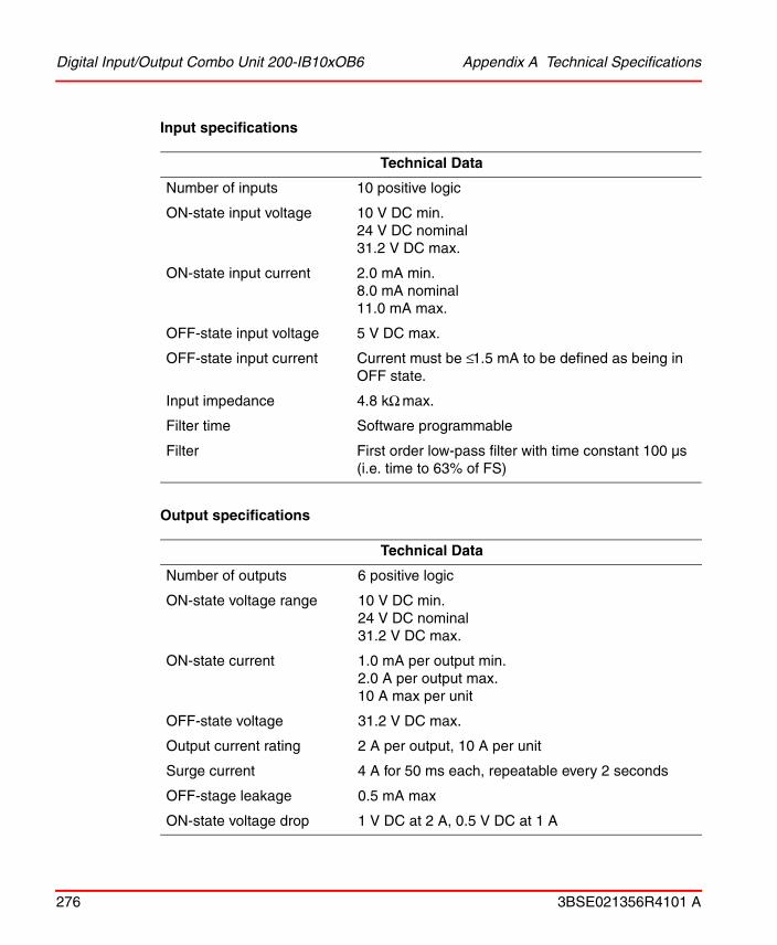
Digital Input/Output Combo Unit 200-IB10xOB6 Appendix A Technical Specifications
276 3BSE021356R4101 A
Input specifications
Output specifications
Technical Data
Number of inputs 10 positive logic
ON-state input voltage 10 V DC min.24 V DC nominal31.2 V DC max.
ON-state input current 2.0 mA min.8.0 mA nominal11.0 mA max.
OFF-state input voltage 5 V DC max.
OFF-state input current Current must be ≤ 1.5 mA to be defined as being in OFF state.
Input impedance 4.8 kΩ max.
Filter time Software programmable
Filter First order low-pass filter with time constant 100 µs (i.e. time to 63% of FS)
Technical Data
Number of outputs 6 positive logic
ON-state voltage range 10 V DC min.24 V DC nominal31.2 V DC max.
ON-state current 1.0 mA per output min.2.0 A per output max. 10 A max per unit
OFF-state voltage 31.2 V DC max.
Output current rating 2 A per output, 10 A per unit
Surge current 4 A for 50 ms each, repeatable every 2 seconds
OFF-stage leakage 0.5 mA max
ON-state voltage drop 1 V DC at 2 A, 0.5 V DC at 1 A

Appendix A Technical Specifications Digital Input Unit 200-IB32
3BSE021356R4101 A 277
Digital Input Unit 200-IB32
Technical Data
Number of inputs 32 positive logic
Galvanic isolation Yes, in two groups via optocouplers
Status indicators 32 yellow LEDs for input indications
ON-state input voltage 19.2 V DC min.24 V DC nominal31.2 V DC max.
ON-state input current 2.0 mA min.4.1 mA nominal at 24V DC6.0 mA max.
OFF-state input voltage 5.0 V DC max.
OFF-state input current Current must be ≤ 1.5 mA to be defined as being in OFF state.
Filter time 0.25 ms, 0.5 ms, 1 ms, 2 ms, 4 ms, 8 ms, 16 ms, 32 ms, software programmable
Input impedance 6.0 kΩ max.
Isolation voltage 1250 V AC for inputs to backplane; 100% tested at 2121V DC for 1 s between user and system, no isolation between individual channels
Internal current consumption (from the serial bus)
35 mA max.
Power dissipation 6.0 W max. at 31.2 V DC

Digital Input Unit 200-IB32 Appendix A Technical Specifications
278 3BSE021356R4101 A
Temperature Operating: 0 °C to +55 °CNon-operating: –40 °C to +85°C
Humidity 5–95%, non-condensing
Approvals (when product or packaging is marked)
C-UL ListedUL Class I, Division 2, Groups A, B, C, D certifiedC-UL Class I, Division 2, Groups A, B, C, D certified
Unit identity 0211 (hex)
Backplane key code 2
Weight 0.249 kg excl. package0.344 kg incl. package
Dimensions W 94 x H 46 x D 53 mm
Order code 200-IB32
Technical Data

Appendix A Technical Specifications Digital Output Unit 200-OB32P
3BSE021356R4101 A 279
Digital Output Unit 200-OB32P
Technical Data
Number of Outputs 32 positive logic
Galvanic isolation Yes, in two groups via optocouplers)
Status indicators 32 yellow LEDs for output indications
ON-state voltage range 10 V DC min.24 V DC nominal31.2 V DC max.
ON-state current 1.0 mA min. per channel500 mA max. per channel14 A max. per unit (6 A total for channels 0-15; 8 A total for channels 16-31
OFF-state voltage 31.2 V DC max.
OFF-state leakage current
0.5 mA max.
ON-state voltage drop 0.5 V DC max.
Isolation voltage 1250 V AC for outputs to backplane; 100% tested at 2121 V DC for 1 s between user and system, no isolation between individual channels
Output Signal DelayOFF to ONON to OFF
0.5 ms max.1.0 ms max.
Surge current 2 A for 50 ms, repeatable every 2 seconds
Power dissipation 5.3 W max. at 31.2 V DC

Digital Output Unit 200-OB32P Appendix A Technical Specifications
280 3BSE021356R4101 A
Internal current consumption (from the serial bus)
80 mA max.
Temperature Operating: 0 °C to +55 °CNon-operating: –40 °C to +85°C
Humidity 5–95%, non-condensing
Approvals (when product or packaging is marked)
C-UL ListedUL Class I, Division 2, Groups A, B, C, D certifiedC-UL Class I, Division 2, Groups A, B, C, D certified
Unit identity 0001 (hex)
Backplane key code 2
External DC powerSupply voltageSupply current
24 V DC nominal (19.2–31.2 V DC)49 mA at 24 V DC (38 mA–65 mA)
Weight 0.267 kg excl. package0.362 kg incl. package
Dimensions W 94 x H 46 x D 53 mm
Fuse Outputs are electronically protected
Order code 200-OB32P
Technical Data

Appendix A Technical Specifications Digital Input/Output Combo Unit 200-IB16xOB16P
3BSE021356R4101 A 281
Digital Input/Output Combo Unit 200-IB16xOB16P
General specifications
Technical Data
Galvanic isolation Input channels are isolated from output channels.
Status indicators 16 yellow LEDs for input indications, and 16 for output indications
Isolation Voltage 1250 V AC for inputs or outputs to backplane and between input and output channels; 100% tested at 2121 V DC for 1 sec between user and system, no isolation between individual channels
Internal current consumption (from serial bus)
100 mA max.
Power dissipation 7.0 W max. at 31.2 V DC
Unit identity 011C (hex)
Backplane key code 2
External DC PowerSupply voltageSupply current
24 V DC nominal (19.2–31.2 V DC)28 mA at 24 V DC (not including outputs)
Temperature (refer to the derating curve on page 283)
Operating: 0 °C to +55 °CNon-operating: –40 °C to +85°C
Humidity 5–95%, non-condensing

Digital Input/Output Combo Unit 200-IB16xOB16P Appendix A Technical Specifications
282 3BSE021356R4101 A
Input specifications
Output specifications
Approvals (when product or packaging is marked)
C-UL ListedUL Class I, Division 2, Groups A, B, C, D certifiedC-UL Class I, Division 2, Groups A, B, C, D certified
Weight 0.300 kg excl. package, 0.395 kg incl. package
Dimensions W 94 x H 46 x D 53 mm
Order code 200-IB16xOB16P
Technical Data
Number of inputs 16 positive logic, non-isolated
ON-state input voltage (refer to the derating curve on page 283)
10 V DC min.24 V DC nominal31.2 V DC max.
ON-state input current 2.0 mA min.8.8 mA nominal12.1 mA max.
OFF-state input voltage 5 V DC max.
OFF-state input current Current must be ≤ 1.5 mA to be defined as being in OFF state.
Input impedance 2.5 kΩ max.
Filter time 0.25 ms, 0.5 ms, 1 ms, 2 ms, 4 ms, 8 ms, 16 ms, 32 ms, software programmable
Technical Data
Number of outputs 16 positive logic, non-isolated
ON-state voltage range (refer to the derating curve on page 283)
10 V DC min.24 V DC nominal31.2 V DC max.

Appendix A Technical Specifications Digital Input/Output Combo Unit 200-IB16xOB16P
3BSE021356R4101 A 283
ON-state current 1.0 mA min. and 0.5 A max. per output 8 A max. per unit
OFF-state voltage 31.2 V DC max.
Output current rating 0.5 A per output, 8 A per unit
Surge current 1.5 A for 50 ms, repeatable every 2 seconds
OFF-stage leakage 0.5 mA max.
ON-state voltage drop Max. 0.5 V DC at 1 A
Output signal delay OFF to ON max. 0.5 msON to OFF max. 1.0 ms
Ambient temperature °C
The area within the curve represents the safe operating range for the unit in all mounting positions, under various conditions of user supplied DC voltages and ambient temperatures.
Derating curve
On-
stat
e in
put v
olta
ge a
nd
on-s
tate
oup
ut v
olta
ge (
VD
C)
30
25
20
15
10
5
0 10 20 30 40 50
26.4
31.2
550

Pulse Counter Unit 200-IP2 Appendix A Technical Specifications
284 3BSE021356R4101 A
Pulse Counter Unit 200-IP2
Technical data
Number of inputs 2 pulse counter interfaces, each with 4 inputs
Counting frequency Max. 100 kHz. Each signal condition must be stable for at least 2 µs to be recognized by the counter logic.
Galvanic isolation Yes (via optocouplers)
Status indicators 2x6 yellow LEDs for I/O status indications and 1 red/green LED for OK status indication
Input range(2x4 input signals)Terminal ”+” and ”-” for each inputInput ON (active)
Input OFF (inactive)
Max. +26.4 V DC (24 V DC +10%)Min. +6 V DC
Max. +3.0 V DCMin. –26.4 V DC
Input current Typically 3 mA at 6 V DCTypically 8 mA at 12 V DCTypically 15 mA at 24 V DC
Voltage range – external power supply
12–24 V DC ±10%
Current consumption - external power supply
150 mA at 12 V DC75 mA at 24 V DC
Isolation voltage Type test voltage 500 V AC (corresponding to 700 V DC) for 1 minute, according to UL508
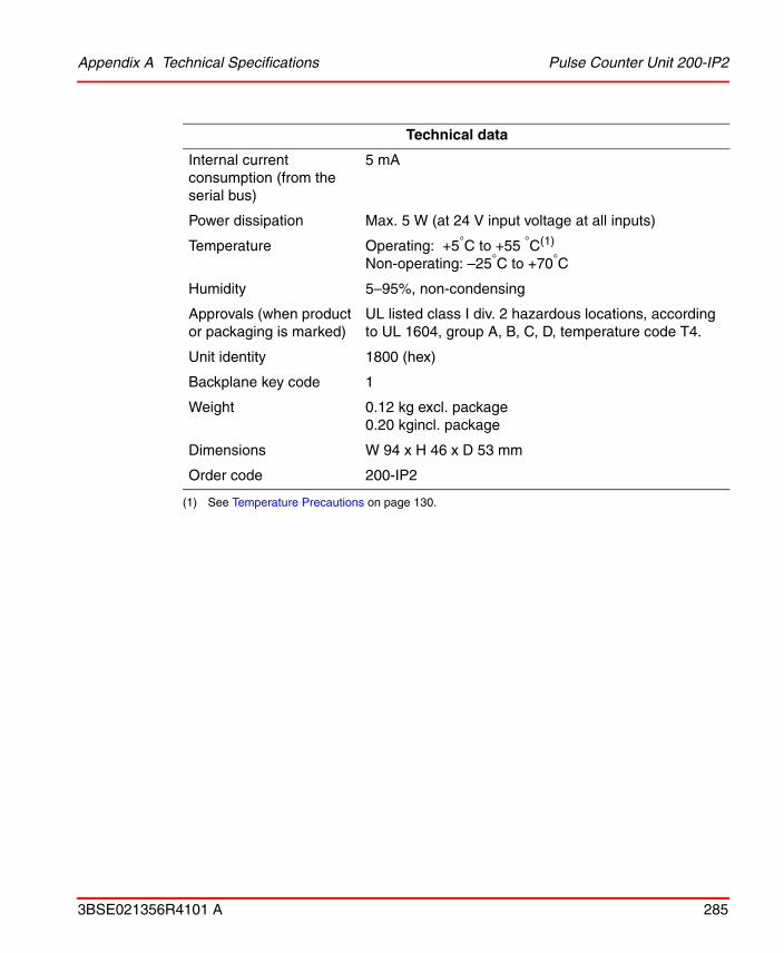
Appendix A Technical Specifications Pulse Counter Unit 200-IP2
3BSE021356R4101 A 285
Internal current consumption (from the serial bus)
5 mA
Power dissipation Max. 5 W (at 24 V input voltage at all inputs)
Temperature Operating: +5°C to +55 °C(1)
Non-operating: –25°C to +70°C
Humidity 5–95%, non-condensing
Approvals (when product or packaging is marked)
UL listed class I div. 2 hazardous locations, according to UL 1604, group A, B, C, D, temperature code T4.
Unit identity 1800 (hex)
Backplane key code 1
Weight 0.12 kg excl. package0.20 kgincl. package
Dimensions W 94 x H 46 x D 53 mm
Order code 200-IP2
(1) See Temperature Precautions on page 130.
Technical data

Frequency Counter Unit 200-IP4 Appendix A Technical Specifications
286 3BSE021356R4101 A
Frequency Counter Unit 200-IP4
Technical data
Number of inputs 4 frequency counter interfaces, each with 2 inputs
Counting frequency Max. 100 kHz. Each signal condition must be stable for at least 2 µs to be recognized by the counter logic.
Min. 15.3 Hz for a 16-bit time period measurement and internal clock = 1 MHz. Only one period can be measured. For lower frequencies, refer to Time period measurement on page 138.Min. 153 Hz for internal clock = 10 MHz
Galvanic isolation Yes (via optocouplers)
Status indicators 4x2 yellow LEDs for I/O status indication, 4x2 yellow LEDs for selected measurement function indication and 1 red/green LED for OK status indication
Input range(4x2 input signals)Terminal ”+” and ”–” for each inputInput ON (active)
Input OFF (inactive)
Max. +26.4 V DC (24 V DC +10%)Min. +6 V DC
Max. +3.0 V DCMin. –26.4 V DC
Input current Typically 3 mA at 6 V DCTypically 8 mA at 12 V DCTypically 15 mA at 24 V DC

Appendix A Technical Specifications Frequency Counter Unit 200-IP4
3BSE021356R4101 A 287
Voltage range – external power supply
12–24 V DC ±10%
Current consumption - external power supply
150 mA at 12 V DC75 mA at 24 V DC
Isolation voltage Type test voltage 500 V AC (corresponding to 700 V DC) for 1 minute, according to UL508
Internal current consumption (from the serial bus)
5 mA
Power dissipation Max. 5 W (at 24 V input voltage at all inputs)
Temperature Operating: +5°C to +55 °C(1)
Non-operating: –25°C to +70°C
Humidity 5–95%, non-condensing
Approvals (when product or packaging is marked)
UL listed class I div. 2 hazardous locations, according to UL 1604, group A, B, C, D, temperature code T4.
Unit identity 1A00 (hex)
Backplane key code 1
Weight 0.12 kg excl. package0.20 kgincl. package
Dimensions W 94 x H 46 x D 53 mm
Order code 200-IP4
(1) See Temperature Precautions on page 144.
Technical data
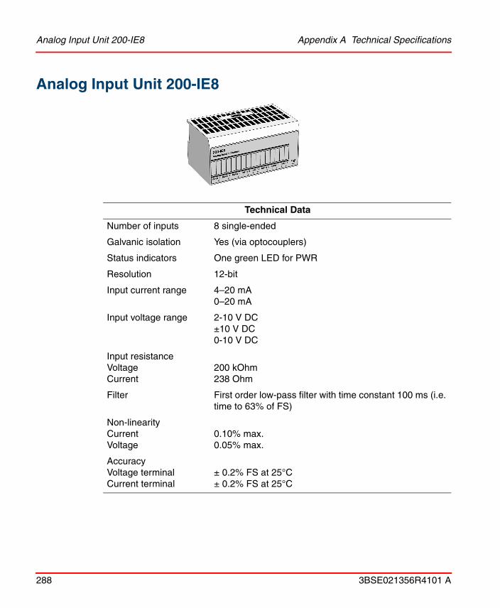
Analog Input Unit 200-IE8 Appendix A Technical Specifications
288 3BSE021356R4101 A
Analog Input Unit 200-IE8
Technical Data
Number of inputs 8 single-ended
Galvanic isolation Yes (via optocouplers)
Status indicators One green LED for PWR
Resolution 12-bit
Input current range 4–20 mA0–20 mA
Input voltage range 2-10 V DC±10 V DC0-10 V DC
Input resistance VoltageCurrent
200 kOhm238 Ohm
Filter First order low-pass filter with time constant 100 ms (i.e. time to 63% of FS)
Non-linearity CurrentVoltage
0.10% max.0.05% max.
AccuracyVoltage terminalCurrent terminal
± 0.2% FS at 25°C± 0.2% FS at 25°C

Appendix A Technical Specifications Analog Input Unit 200-IE8
3BSE021356R4101 A 289
Accuracy drift with temperatureVoltage terminalCurrent terminal
± 0.0043% FS/°C± 0.0041% FS/°C
Repeatability ± 0.05% of FS
Overload(1)VoltageCurrent
30 V DC continuously32 mA continuously, one channel at a time max.
Isolation Voltage Type test voltage: 850 V DC for 1 s between plant and system. No isolation between individual channels.
Internal current consumption (from serial bus)
20 mA max.
Power dissipation 3 W at 31.2V DC max.
Temperature Operating: 0 °C to +55 °CNon-operating: –40 °C to +85°C
Humidity Operating: 5–95%, non-condensingNon-operating:5–80%, non-condensing
Approvals (when product or packaging is marked)
CSA certified; class I div. 2 hazardous locations, group A, B, C, D, temperature code T6
European Ex certified, class I, zone 2, group II C
Unit identity 1924 (hex)
Backplane key code 3
External DC Power Supply voltageSupply current
24 V DC nominal (19.2–31.2 V DC)60 mA at 24 V DC (typ.)
Weight 0.085 kg excl. package0.180 kg incl. package
Dimensions W 94 x H 46 x D 53 mm
Order code 200-IE8
(1) Without damage.
Technical Data

Analog Output Unit 200-OE4 Appendix A Technical Specifications
290 3BSE021356R4101 A
Analog Output Unit 200-OE4
Technical Data
Number of outputs 4
Galvanic isolation Yes (via optocouplers)
Status indicators One green LED for PWR
Resolution 12-bit plus sign
Output current range 4–20 mA 0–20 mA
Output voltage range 2–10 V DC, ±10 V DC, 0–10 V DC
Filter First order low-pass filter with time constant 24 ms (i.e. time to 63% of FS)
Current load on voltage output
3 mA max.
Resistive load on mAoutput
15–750 Ohms
Non-linearity CurrentVoltage
0.1%0.1%
AccuracyVoltage terminalCurrent terminal
± 0.13% FS at 25°C± 0.43% FS at 25°C

Appendix A Technical Specifications Analog Output Unit 200-OE4
3BSE021356R4101 A 291
Accuracy drift with temperatureVoltage terminalCurrent terminal
± 0.005% FS/°C± 0.007% FS/°C
Isolation Voltage Type test voltage: 850 V DC for 1 s between plant and system. No isolation between individual channels.
Internal current consumption (from serial bus)
20 mA max.
Power dissipation 4.5 W at 31.2 V DC max.
Unit identity 1125 (hex)
Backplane key code 4
External DC Power Supply voltageSupply current
24 V DC nominal (19.2–31.2 V DC)70 mA at 24V DC (not including outputs)
Temperature Operating: 0 °C to +55 °CNon-operating: –40 °C to +85°C
Humidity Operating: 5–95%, non-condensingNon-operating:5–80%, non-condensing
Approvals (when product or packaging is marked)
CSA certified; class I div. 2 hazardous locations, group A, B, C, D, temperature code T6
European Ex certified, class I, zone 2, group II C
Weight 0.085 kg excl. package0.180 kg incl. package
Dimensions W 94 x H 46 x D 53 mm
Order code 200-OE4
Technical Data

Input/Output Analog Combo Unit 200-IE4xOE2 Appendix A Technical Specifications
292 3BSE021356R4101 A
Input/Output Analog Combo Unit 200-IE4xOE2
Technical Data
Number of inputs 4 single-ended
Numberr of outputs 2 single-ended
Galvanic isolation Yes (via optocouplers)
Status indicators One green LED for PWR
Resolution 12-bit
Isolation Voltage Type test voltage: 850 V DC for 1 s between plant and system. No isolation between individual channels.
Internal current consumption (from serial bus)
20 mA max.
Power dissipation 4.0 W at 31.2 V DC max.
Unit identity 1526 (hex)
Backplane key code 5
External DC Power Supply voltageSupply current
24 V DC nominal (19.2 to 31.2 V DC)70 mA at 24V DC (not including outputs)
Temperature Operating: +0°C to +55 °CNon-operating: –40°C to +85°C
Approvals (when product or packaging is marked)
CSA certified; class I div. 2 hazardous locations, group A, B, C, D, temperature code T6
European Ex certified, class I, zone 2, group II C

Appendix A Technical Specifications Input/Output Analog Combo Unit 200-IE4xOE2
3BSE021356R4101 A 293
For input specifications see 200-IE8 and for output specifications see 200-OE4.
Humidity Operating: 5–95%, non-condensingNon-operating:5–80%, non-condensing
Weight 0.085 kg excl. package, 0.180 kg incl. package
Dimensions W 94 x H 46 x D 53 mm
Order code 200-IE4xOE2

Analog Input Unit 200-IF4I Appendix A Technical Specifications
294 3BSE021356R4101 A
Analog Input Unit 200-IF4I
Technical Data
Number of inputs 4 isolated
Status indicators One bi-polar (green/red) LED for OK
Resolution 16-bit unipolar, 15 bits plus sign bipolar
Input current range 4–20 mA0–20 mA
Input voltage range ± 5 V DC, 0–5 V DC± 10 V DC, 0–10 V DC
Input resistanceVoltageCurrent
> 10 Mohm< 100 ohm
Filter First order low-pass filter with time constant 100 ms, 500 ms or 1000 ms (i.e. time to 63% of FS), or no low-pass
AccuracyVoltage terminalCurrent terminal
± 0.1% FS at 25°C.± 0.1% FS at 25°CBoth include offset, gain, non-linearity and repeatability errors
Accuracy drift with temperatureVoltage terminalCurrent terminal
± 0.0028% FS/°C± 0.0038% FS/°C

Appendix A Technical Specifications Analog Input Unit 200-IF4I
3BSE021356R4101 A 295
Overload (without damage)Voltage Current
30 V DC continuously32 mA continuously, one channel at a time max.
Isolation Voltage Factory test voltage: 2550 V DC for 1 s between channel to channel, channel to user power, channel to system or user power to system
Internal current consumption (from serial bus)
50 mA max.
Power dissipation 2 W at 31.2V DC max.
Temperature Operating: 0 °C to +55 °CNon-operating: –40 °C to +85°C
Humidity Operating: 5–95%, non-condensingNon-operating:5–80%, non-condensing
Approvals (when product or packaging is marked)
CSA certified; class I div. 2 hazardous locations, group A, B, C, D, temperature code T4A
European Ex certified, class I, zone 2, group II C
Unit identity 1720 (hex)
Backplane key code 3
External DC Power Supply voltageSupply current
24 V DC nominal (19.2–31.2 V DC)80 mA at 24 V DC (typ.)
Weight 0.085 kg excl. package0.180 kg incl. package
Dimensions W 94 x H 46 x D 53 mm
Order code 200-IF4I
Technical Data

Analog Output Unit 200-OF4I Appendix A Technical Specifications
296 3BSE021356R4101 A
Analog Output Unit 200-OF4I
Technical Data
Number of outputs 4 isolated
Status indicators One bi-polar (green/red) LED for OK
Resolution 15-bit plus sign
Output current range 4–20 mA 0–20 mA
Output voltage range ± 5 V DC, ± 10 V DC0–5 V DC, 0–10 V DC
Filter Step response to 63% of FS < 25μs
Current load on voltage output
3 mA max.
Resistive load on mAoutput
0–750 Ohms
AccuracyVoltage terminalCurrent terminal
± 0.1 % FS at 25°C± 0.1 % FS at 25°CBoth include offset, gain, non-linearity and repeatability errors
Accuracy drift with temperatureVoltage terminalCurrent terminal
± 0.0012% FS/°C± 0.0025% FS/°C

Appendix A Technical Specifications Analog Output Unit 200-OF4I
3BSE021356R4101 A 297
Isolation Voltage Factory test voltage: 2550 V DC for 1 s between channel to channel, channel to user power, channel to system or user power to system
Internal current consumption (from serial bus)
50 mA max.
Power dissipation 4.7 W at 31.2 V DC max.
Unit identity 1621 (hex)
Backplane key code 4
External DC Power Supply voltageSupply current
24 V DC nominal (19.2 to 31.2 V DC)210 mA at 24V DC
Temperature Operating: 0 °C to +55 °CNon-operating: –40 °C to +85°C
Humidity Operating: 5–95%, non-condensingNon-operating:5–80%, non-condensing
Approvals (when product or packaging is marked)
CSA certified; class I div. 2 hazardous locations, group A, B, C, D, temperature code T4A
European Ex certified, class I, zone 2, group II C
Weight 0.085 kg excl. package0.180 kg incl. package
Dimensions W 94 x H 46 x D 53 mm
Order code 200-OF4I
Technical Data

RTD Input Unit 200-IR8 Appendix A Technical Specifications
298 3BSE021356R4101 A
RTD Input Unit 200-IR8
Technical Data
Number of inputs 8
Galvanic isolation Yes
Status indicators Bi-colour (green/red) LED for OK
Resolution 16-bit
Input range 1–433 Ω
Overvoltage capability ±35 V DC, 25 V AC continuous at 25 °C, 250 V peak transient
Accuracy without calibration and at low humidity levels
0.05% of FSR max. in normal mode (0.01% of FSR typ. in enhanced mode) at 25 °C
Internal current consumption (from serial bus)
20 mA max.
Filter Programmable
Normal mode noise rejection 60 dB at 60 Hz for A/D filter cut-off at 15 Hz
Calibration Programmable
Common mode rejection 120 dB at 60 Hz; 100 dB at 50 Hz for A/D filter cut-off at 10 Hz
System throughput Normal mode, programmable 28 ms–325 ms/channelEnhanced mode, programmable 56 ms–650 ms/channel
Open-wire detection Out of range reading (upscale)

Appendix A Technical Specifications RTD Input Unit 200-IR8
3BSE021356R4101 A 299
Open-wire detection time 1 s typ.
RTD exitation current 718 µA
Input offset drift with temp. 1.5 mΩ/°C max.
Gain drift with temperatureNormal modeEnhanced mode
20 ppm/°C10 ppm/°C
Temperature (see derating curve on next page)
Operating: 0 °C to +55 °CNon-operating: –40 °C to +85°C
Humidity Operating: 5–95%, non-condensingNon-operating: 5–80%, non-condensing
Approvals (when product or packaging is marked)
CSA certified; class I div. 2 hazardous locations, group A, B, C, D, temperature code T5
European Ex certified, class I, zone 2, group II C
Supported sensors (resistance)
1–433 Ω
500 Ω Pt Euro -200 to +630 °C (α=0.00385)200 Ω Pt Euro -200 to +630 °C(α=0.00385)100 Ω Pt Euro -200 to +870 °C (α=0.00385)100 Ω Pt U.S. -200 to +630 °C (α=0.00392)500 Ω Ni -60 to +250 °C (α=0.00618)200 Ω Ni -60 to +250 °C (α=0.00618)120 Ω Ni -60 to +250 °C (α=0.00672)100 Ω Ni -60 to +250 °C (α=0.00618)10 Ω Cu -200 to +260 °C (α=0.00427)
Unit identity 1B01 (hex)
Backplane key code 3
External DC Power Supply voltageSupply current
24 V DC nominal (19.2–31.2 V DC)60 mA at 24V DC
Power dissipation 3 W at 31.2 V DC max.
Weight 0.085 kg excl. package, 0.180 kg incl. package
Dimensions W 94 x H 46 x D 53 mm
Order code 200-IR8
Technical Data

RTD Input Unit 200-IR8 Appendix A Technical Specifications
300 3BSE021356R4101 A
The area within the curve represents the safe operating range for the unit under various conditions of 24 V DC input voltage and ambient temperatures.
Derating curve
Supply voltage
Ambient temperature

Appendix A Technical Specifications RTD Input Unit 200-IR8R
3BSE021356R4101 A 301
RTD Input Unit 200-IR8R
Technical Data
Number of inputs 8
Galvanic isolation Yes
Status indicators 8 yellow LEDs for I/O status indication and 1 green LED for OK status indication
Resolution 16-bit
Input range -60 °C to +160 °C
Overvoltage capability ±35 V DC, 25 V AC continuous at 25 °C, 250 V peak transient
Accuracy ±0.1°C in the range –5 to +100 °C
Long term stability 1 year: ±0.006 °C3 years: ±0.013 °C
Internal current consumption (from serial bus)
20 mA max.
Filter Programmable
Normal mode noise rejection 60 dB at 50 Hz for A/D filter cut-off at 10 Hz
Calibration Factory calibrated
Common mode rejection 120 dB at 60 Hz; 100 dB at 50 Hz for A/D filter cut-off at 10 Hz
System throughput 150 ms/channel at 50 Hz
Open or short-circuit RTD detection
Out of range reading and individual fault indication

RTD Input Unit 200-IR8R Appendix A Technical Specifications
302 3BSE021356R4101 A
Open-wire detection or short-circuit detection time
< 1 s
RTD excitation current ≈ 1.8 mA, alternating direction
RTD algorithm ITS 90
Temperature (see derating curve on next page
Operating: +5 °C to +55 °CNon-operating: –25 °C to +70°C
Humidity Operating: 5–95%, non-condensingNon-operating:5–80%, non-condensing
Approvals (when product or packaging is marked)
UL listed class I div. 2 hazardous locations, according to UL 1604, group A, B, C, D, temperature code T4.
European Ex certified, class I, zone 2, group II C
Supported sensors (resistance)
100 Ω Pt Euro -60 to +160°C (α=0.00385)IEC 751
Unit identity 1900 (hex)
Backplane key code 3
External DC Power Supply voltageSupply current
24 V DC nominal (19.2–30.0 V DC)100 mA at 24V DC
Power dissipation 3 W at 30.0 V DC max.
Weight 0.085 kg excl. package0.180 kg incl. package
Dimensions W 94 x H 46 x D 53 mm
Order code 200-IR8R
Technical Data

Appendix A Technical Specifications RTD Input Unit 200-IR8R
3BSE021356R4101 A 303
The area within the curve curve represents the safe operation range for the unit under various conditions of 24 V DC supply voltage and ambient temperatures.
Derating curve
Supply voltage
Ambient temperature

Thermocouple Input Unit 200-IT8 Appendix A Technical Specifications
304 3BSE021356R4101 A
Thermocouple Input Unit 200-IT8
Technical Data
Number of inputs 8
Galvanic isolation Yes
Status indicators Bi-colour (green/red) LED for OK
Resolution 16-bit
Input voltage range ± 76.5 mV DC
Overvoltage capability 35 V DC, 25 V AC continuous at 25 °C, 250 V peak transient
Accuracy with filter 0.025% of FSR ± 0.5 °C max.
Accuracy without filter 0.05% of FSR ± 0.5 °C max.
Internal current consumption (from serial bus)
20 mA max.
Filter Programmable
Normal mode noise rejection
-60 dB at 60 Hz
Common mode rejection -115 dB at 60 Hz; -100 dB at 50 Hz
System throughput Programmable 28–325 ms for 1 channel; 2.6 s for 8 channels
Open thermocouple detection
Out of range reading (upscale)

Appendix A Technical Specifications Thermocouple Input Unit 200-IT8
3BSE021356R4101 A 305
Open thermocouple detection time
1 s typ.
Input offset drift with temperature
±6 µV/°C max.
Gain drift with temperature
10 ppm/°C
Overall drift with temperature
50 ppm 1°C of span max.
Temperature (see derating curve on next page
Operating: 0 °C to +55 °CNon-operating: –40 °C to +85°C
Humidity Operating: 5–95%, non-condensingNon-operating:5–80%, non-condensing
Approvals (when product or packaging is marked)
CSA certified; class I div. 2 hazardous locations, group A, B, C, D, temperature code T5
European Ex certified, class I, zone 2, group II C
Supported thermocouple types
millivolt ± 76.5 mV
Type B: 300–1800 °CC: 0–2315 °CE: -270–1000 °CJ: -210–1200 °CK:-270–1372 °CN:-270–1300 °CR:-50–1768 °CS:-50–1768 °CT:-270–400 °C
Unit identity 1B00 (hex)
Backplane key code 3
External DC Power Supply voltageSupply current
24 V DC nominal (19.2–31.2 V DC)60 mA at 24V DC
Power dissipation 3 W at 31.2 V DC max.
Technical Data

Thermocouple Input Unit 200-IT8 Appendix A Technical Specifications
306 3BSE021356R4101 A
Weight 0.085 kg excl. package0.180 kg incl. package
Dimensions W 94 x H 46 x D 53 mm
Order code 200-IT8
Technical Data
Supply voltage
Ambient temperature
Derating curve
The area within the curve represents the safe operating range for the unit under various conditions of 24 V DC input voltage and ambient temperatures.

Appendix A Technical Specifications AC Input Unit 200-IA8
3BSE021356R4101 A 307
AC Input Unit 200-IA8
Technical Data
Number of inputs 8 (1 group of 8)
Galvanic isolation Yes (via optocouplers)
Status indicators 8 yellow (field side indication)
ON-state voltage 65 V AC min.
OFF-state voltage 43 V AC max.
ON-state current 7.1 mA min.
OFF-state current 2.9 mA max.
Filter time Software programmable
Filter First order low-pass filter with time constant 8 ms
Isolation voltage 100% tested at 2150 V AC for 1 s between user and system. No isolation between individual channels
Input impedance 10.6 kΩ nominal
Internal current consumption (from serial bus)
30 mA max.
Power dissipation 4.5 W at 132 V AC max.
Temperature Operating: 0 °C to +55 °CNon-operating: –40 °C to +85°C
Humidity 5–95%, non-condensing

AC Input Unit 200-IA8 Appendix A Technical Specifications
308 3BSE021356R4101 A
Approvals (when product or packaging is marked)
CSA certified; class I div. 2 hazardous locations, group A, B, C, D, temperature code T4A.European Ex certified, class I, zone 2, group II C
Unit identity 0285 (hex)
Backplane key code 8
External AC Power Supply voltageInput frequencyVoltage range
120 V AC nominal47–63 Hz85–132 V AC
Weight 0.085 kg excl. package, 0.180 kg incl. package
Dimensions W 94 x H 46 x D 53 mm
Order code 200-IA8
Technical Data

Appendix A Technical Specifications AC Output Unit 200-OA8
3BSE021356R4101 A 309
AC Output Unit 200-OA8
Technical Data
Number of outputs 8 (1 group of 8)
Galvanic isolation Yes (via optocouplers)
Status indicators 8 yellow LEDs
Output voltage range 85–132 V AC , 47–63 Hz
Output current range 4.0 A (8 outputs at 500 mA)
ON-state voltage drop 1.0 V AC at 0.5 A min.
Inrush current 7 A for 45 ms, repetable every 8 seconds
OFF-state leakage 2.25 mA max.
Isolation voltage 100% tested at 1250 V AC for 1 s between user and system. No isolation between individual channels
Output signal delayOFF to ONON to OFF
1/2 cycle max.1/2 cycle max.
Internal current consumption (from serial bus)
80 mA max.
Power dissipation 5.2 W at 132 V AC.
Unit identity 0195 (hex)
Backplane key code 8

AC Output Unit 200-OA8 Appendix A Technical Specifications
310 3BSE021356R4101 A
External AC Power Supply voltageInput frequencyVoltage rangeSupply currentSurge current capability
120 V AC nominal47–63 Hz85–132 V AC150 mA min.50 A for 1/2 cycle at power-up max.
Temperature Operating: 0 °C to +55 °CNon-operating: –40 °C to +85°C
Humidity 5–95%, non-condensing
Approvals (when product or packaging is marked)
CSA certified; class I div. 2 hazardous locations, group A, B, C, D, temperature code T4A
European Ex certified, class I, zone 2, group II C
Weight 0.085 kg excl. package0.180 kg incl. package
Dimensions W 94 x H 46 x D 53 mm
Fuse 1.6 A, slow (when used in TBNF)
Order code 200-OA8
Technical Data

Appendix A Technical Specifications AC Input Unit 200-IM8
3BSE021356R4101 A 311
AC Input Unit 200-IM8
Technical Data
Number of inputs 8 (1 group of 8)
Unit location On terminal base 200-TBN
Unit mounting See derating curve below
Galvanic isolation Yes (via optocouplers)
Status indicators 8 yellow (field side indication)
ON-state voltage 159 V AC min.
OFF-state voltage 40 V AC max.
ON-state current 11 mA min. at 230 V AC
OFF-state current 2.6 mA max.
Input delay time Software programmable
Input delay time (max.) OFF to ON (time from valid input signal to recognition by the logic).
ON to OFF (time from input dropping below valid level to recognition by the logic)
7.5 ms, 8 ms, 9 ms, 10 ms, 12 ms, 16 ms, 24.5 ms, 42 ms (default: 7.5 ms)
26.5 ms, 27 ms, 28 ms, 29 ms, 31 ms, 35 ms, 44 ms, 60.5 ms (default: 26.5 ms)

AC Input Unit 200-IM8 Appendix A Technical Specifications
312 3BSE021356R4101 A
Isolation voltage 100% tested at 2600 V DC for 1 s between user and system. No isolation between individual channels and no isolation between customer power to input channels.
Input impedance 22.3 kΩ nominal
Internal current consumption (from serial bus)
30 mA max. at 5 V DC
Power dissipation 4.7 W at 264 V AC max.
Temperature (see derating curve on next page
Operating: 0 °C to +55 °CNon-operating: –40 °C to +85 °C
Humidity 5–95%, non-condensing
Approvals (when product or packaging is marked)
CSA certified; class I div. 2 hazardous locations, group A, B, C, D, temperature code T4
European Ex certified, class I, zone 2, group II C
Unit identity 0205 (hex)
Backplane key code 8
External AC Power Supply voltageInput frequencyVoltage range
230 V AC nominal47–63 Hz159–264 V AC
Weight 0.085 kg excl. package0.180 kg incl. package
Dimensions W 94 x H 46 x D 53 mm
Order code 200-IM8
Technical Data

Appendix A Technical Specifications AC Input Unit 200-IM8
3BSE021356R4101 A 313
The area within the curve represents the safe operating range for the unit under various conditions of 230 V DC input voltage and ambient temperatures.
+ = Normal mounting safe operating range. = Other mounting positions (including inverted horizontal, vertical) safe operating
range.
Derating curve
Vin On-state Voltage (V AC)
Ambient temperature 0 oC
264
0 5546
250
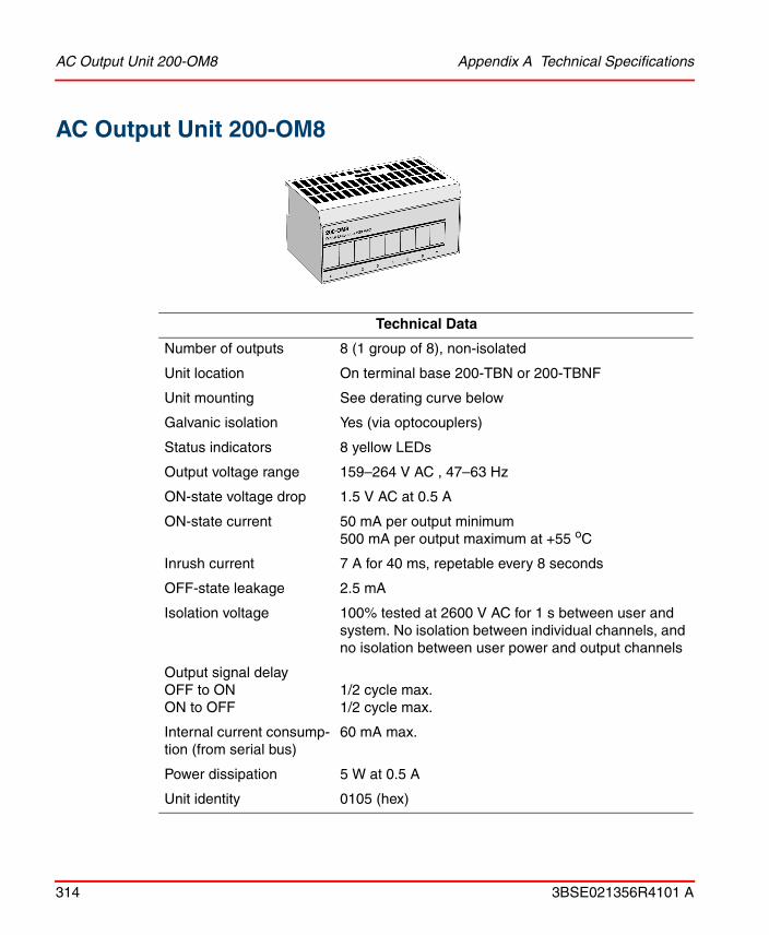
AC Output Unit 200-OM8 Appendix A Technical Specifications
314 3BSE021356R4101 A
AC Output Unit 200-OM8
Technical Data
Number of outputs 8 (1 group of 8), non-isolated
Unit location On terminal base 200-TBN or 200-TBNF
Unit mounting See derating curve below
Galvanic isolation Yes (via optocouplers)
Status indicators 8 yellow LEDs
Output voltage range 159–264 V AC , 47–63 Hz
ON-state voltage drop 1.5 V AC at 0.5 A
ON-state current 50 mA per output minimum500 mA per output maximum at +55 oC
Inrush current 7 A for 40 ms, repetable every 8 seconds
OFF-state leakage 2.5 mA
Isolation voltage 100% tested at 2600 V AC for 1 s between user and system. No isolation between individual channels, and no isolation between user power and output channels
Output signal delayOFF to ONON to OFF
1/2 cycle max.1/2 cycle max.
Internal current consump-tion (from serial bus)
60 mA max.
Power dissipation 5 W at 0.5 A
Unit identity 0105 (hex)

Appendix A Technical Specifications AC Output Unit 200-OM8
3BSE021356R4101 A 315
Backplane key code 8
External AC Power Supply voltageInput frequencyVoltage range
230 V AC nominal47–63 Hz159–264 V AC
Temperature (see derating curve below)
Operating: 0 °C to +55 °CNon-operating: –40 °C to +85°C
Humidity 5–95%, non-condensing
Approvals (when product or packaging is marked)
CSA certified; class I div. 2 hazardous locations, group A, B, C, D, temperature code T4A
European Ex certified, class I, zone 2, group II C
Weight 0.085 kg excl. package0.180 kg incl. package
Dimensions W 94 x H 46 x D 53 mm
Fuse 0.8 A (when used in 200-TBNF)
Order code 200-OM8
Technical Data
The area within the curve represents the safe operating range for the unit under various conditions of 230 V DC input voltage and ambient temperatures.
+ = Normal mounting safe operating range. = Other mounting positions (including inverted horizontal, vertical) safe operating
range.
Derating curve
Vin On-state Voltage (V AC)
Ambient temperature 0C
264
0 5549

Relay Output Unit 200-OW8 Appendix A Technical Specifications
316 3BSE021356R4101 A
Relay Output Unit 200-OW8
Technical Data
Number of outputs 8 (1 group of 8), normally open electromechanical relays
Galvanic isolation Yes (via optocouplers and relays)
Status indicators 8 yellow LEDs
Output voltage range (load dependent)
5–30 V DC at 2.0 A resistive48 V DC at 0.5 A resistive125 V AC at 2.0 A resistive125 V DC at 0.25 A resistive240 V AC at 2.0 A resistive
Output current rating (at rated power)
Resistive
Inductive
2 A at 5–30 V DC0.5 A at 48 V DC0.25 A at 125 V DC2 A at 125 V AC2 A at 240 V AC
2.0 A steady state at 5-30 V DC, L/R=7 ms0.5 A steady state at 48 V DC, L/R=7 ms0.25 A steady state at 125 V DC, L/R=7 ms2.0 A steady state, 15 A make at 125 V AC, cos ϕ = 0.42.0 A steady state, 15 A make at 240 V AC, cos ϕ = 0.4

Appendix A Technical Specifications Relay Output Unit 200-OW8
3BSE021356R4101 A 317
Power rating (steady state)
Resistive
Inductive
480 W max. for 240 V AC250 W max. for 125 V AC60 W max. for 30 V DC24 W max. for 48 V DC31 W max. for 125 V DC
480 VA max. for 240 V AC250 VA max. for 125 V AC60 VA max. for 30 V DC24 VA max. for 48 V DC31 VA max. for 125 V DC
Initial contact resistance 30 mΩ
Switching frequency 1 operation/3s (0.3 Hz at rated load) max.
Operate/Release time 10 ms max.
Bounce time 1.2 ms mean
Contact load 100 µA at 100 mV DC min.
Expected life of electrical contacts
100,000 operations min. at rated loads
OFF-state leakage current
1 mA max. at 240 V AC thru snubber circuit
Isolation voltage between any 2 sets of contacts
customer load to logic
customer load to 24 V DC supply
customer 24 V DC supply to logic
2550 V DC for 1 s
2550 V DC for 1 s
2550 V DC for 1 s
850 V DC for 1 s
Technical Data

Relay Output Unit 200-OW8 Appendix A Technical Specifications
318 3BSE021356R4101 A
Output signal delayOFF to ON
ON to OFF
8 ms max. (time from a valid output on signal to relay energization by the module)
26 ms max.(time from a valid output on signal to relay deenergization by the module)
Internal current consumption (from serial bus)
69 mA max.
Power dissipation 5.5 W max.
Temperature Operating: 0 °C to +55 °CNon-operating: –40 °C to +85 °C
Humidity 5–95%, non-condensing
Approvals (when product or packaging is marked)
Meets URLR150 and C300;Meets IEC 1131 AC-15 Utilization Category
CSA certified; class I div. 2 hazardous locations, group A, B, C, D, temperature code T5
European Ex certified, class I, zone 2, group II C
Unit identity 0199 (hex)
Backplane key code 9
External AC Power Supply voltage
Voltage range
Supply current
24 V DC
19.2–31.2 V DC (includes 5% ripple)
125 mA max.
Fuse Max 3 A (when used in TBNF)
Weight 0.085 kg excl. package, 0.180 kg incl. package
Dimensions W 94 x H 46 x D 53 mm
Order code 200-OW8
Technical Data

Appendix A Technical Specifications Short-Circuit-Proof Output Unit 200-OB8EP
3BSE021356R4101 A 319
Short-Circuit-Proof Output Unit 200-OB8EP
Technical Data
Number of outputs 8 (1 group of 8)
Galvanic isolation Yes (via optocouplers)
Status indicators 8 yellow LEDs for status indication and 8 red LEDs for diagnostic fault indication
Output current rating 10 A (e.g. 8 outputs at 1.25 A, 5 outputs at 2.0 A or similar output/ampere combinations totaling 10 A or less). Max. 2.0 A per output.
ON-state voltage range 19.2 V DC min24 V DC nomina31.2 V DC max.
ON-state voltage drop 0.2 V DC max.
Surge current 4 A for 10 ms, repeatable every 3 seconds
OFF-state voltage 31.2 V DC max.
OFF-state leakage 0.5 mA max.
ON-state current 1.0 A min. per channel2.0 A max. per channel
Isolation voltage 100% tested at 850 V AC for 1 s between user and system. No isolation between individual channels
Output signal delay
OFF to ONON to OFF
0.4 ms max.0.2 ms max.

Short-Circuit-Proof Output Unit 200-OB8EP Appendix A Technical Specifications
320 3BSE021356R4101 A
Internal current consumption (from serial bus)
73 mA max.
Power dissipation 5.5 W at 31.2 V DC max.
Temperature Operating: 0 °C to +55 °CNon-operating: –40 °C to +85 °C
Humidity 5–95%, non-condensing
Approvals (when product or packaging is marked)
CSA certified; class I div. 2 hazardous locations, group A, B, C, D, temperature code T4A
European Ex certified, class I, zone 2, group II C
Unit identity 019D (hex)
Backplane key code 2
External DC power
Supply voltage:Voltage Range:Supply current:
24 V DC19.2–31.2 V DC80 mA at 24 V DC
Weight 0.085 kg excl. package0.180 kg incl. package
Dimensions W 94 x H 46 x D 53 mm
Order code 200-OB8EP
Technical Data

Appendix A Technical Specifications Dummy Unit 200-DUTB
3BSE021356R4101 A 321
Dummy Unit 200-DUTB
Technical Data
Temperature Operating: 0 °C to +55 °CNon-operating: –40 °C to +85 °C
Humidity Operating: 5–95%, non-condensing
Backplane key code None
Weight 0.05 kg excl. package0.12 kg incl. package
Dimensions W 94 x H 46 x D 53 mm
Order code 200-DUTB

Adapter for Central I/O System 200-ANN Appendix A Technical Specifications
322 3BSE021356R4101 A
Adapter for Central I/O System 200-ANN
Technical Data
I/O capacity 8 Terminal base units max.
Status indicators 2 green LEDs for Power and Comm
Internal current consumption (from serial bus)
120 mA
Temperature Operating: 0 °C to +55 °CNon-operating: –40 °C to +85 °C
Humidity 5–95%, non-condensing
Approvals (when product or packaging is marked)
CSA certified; class I div. 2 hazardous locations, group A, B, C, D, temperature code T6
European Ex certified, class I, zone 2, group II C
Weight 0.090 kg excl. package0.185 kg incl. package
Dimensions W 68 x H 88 x D 69 mm
Order code 200-ANN
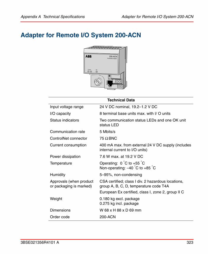
Appendix A Technical Specifications Adapter for Remote I/O System 200-ACN
3BSE021356R4101 A 323
Adapter for Remote I/O System 200-ACN
Technical Data
Input voltage range 24 V DC nominal, 19.2–1.2 V DC
I/O capacity 8 terminal base units max. with I/ O units
Status indicators Two communication status LEDs and one OK unit status LED
Communication rate 5 Mbits/s
ControlNet connector 75 Ω BNC
Current consumption 400 mA max. from external 24 V DC supply (includes internal current to I/O units)
Power dissipation 7.6 W max. at 19.2 V DC
Temperature Operating: 0 °C to +55 °CNon-operating: –40 °C to +85 °C
Humidity 5–95%, non-condensing
Approvals (when product or packaging is marked)
CSA certified; class I div. 2 hazardous locations, group A, B, C, D, temperature code T4A
European Ex certified, class I, zone 2, group II C
Weight 0.180 kg excl. package0.275 kg incl. package
Dimensions W 68 x H 88 x D 69 mm
Order code 200-ACN

Adapter for ProfiBus 200-APB12 Appendix A Technical Specifications
324 3BSE021356R4101 A
Adapter for ProfiBus 200-APB12
Technical Data
Input voltage range +24 V DC nominal, 19.2–31.2 V DC
I/O capacity 8 I/O units
Status indicators 2 red/green LEDs for unit status and communication status
Communication rate Up to 12 Mbit/s
Current consumption 400 mA max. from external 24 V DC supply (includes internal current to I/O units)
Power dissipation 7.68 W max. at 19.2 V DC
Temperature Operating: 0 °C to +55 °CNon-operating: –40 °C to +85°C
Humidity 5–95%, non-condensing
Weight 0.18 kg excl. package0.27 kg incl. package
Dimensions W 68 x H 88 x D 69 mm
Agency certification PNO (PROFIBUS Nutzerorganisation, PROFIBUS User Organization)
UL listed for US and Canada according to UL 508 as open equipment, and for hazardous locations according to UL 1604
Order code 200-APB12

Appendix A Technical Specifications Adapter for Serial I/O bus 200-AIO
3BSE021356R4101 A 325
Adapter for Serial I/O bus 200-AIO
Technical Data
I/O capacity 8 S200 I/O or S200L I/O units (can be mixed)
Max. current from internal 5 V DC
0.64 A
Status indicators None
Connectors One 15-pole female high-density D-type connectorOne male serial I/O bus connectorThe screw terminals are not used
Approvals (when product or packaging is marked)
UL listed for US and Canada according to UL 508 as open equipment, and for hazardous locations according to UL 1604
Weight 0.100 kg excl. package0.195 kg incl. package
Dimensions W 68 × H 88 × D 69 mm
Order code 200-AIO

Power Supply Unit 200-PS1.3 Appendix A Technical Specifications
326 3BSE021356R4101 A
Power Supply Unit 200-PS1.3
Technical Data
Input Voltage Range
Nominal Supply Voltage
85–265 V AC
120 V AC, 47–63 Hz, 0.6 A maximum230 V AC, 47–63 Hz, 0.42 A maximum
Inrush Current 40 A typical for 1 AC cycle at Vin 265 V AC, 55°C
Interruption Output voltage will stay within specification when input drops out for 1/2 cycle at 47 Hz, 85 V AC with maximum load
Nominal Output 24 V DC
Voltage Range 20.4–27.6 V DC (includes noise and 5% ripple)
Output Current 1.3 A max.
Load 0 mA min.
Output Surge Sufficient to drive 4 adapters (surge of 23 A for 2 ms each)
Overvoltage Protection Output internally limited to 35 V DC. Cycle power to reenergize.
Connectors Screw terminals
Isolation Voltage 2500 V DC for 1 second
Temperature Operating: 0 °C to +55 °CNon-operating: –40 °C to +85°C

Appendix A Technical Specifications Power Supply Unit 200-PS1.3
3BSE021356R4101 A 327
Humidity 5–95%, non-condensing
Approvals (when product or packaging is marked)
CULUS certified; class I div. 2 hazardous locations, group A, B, C, D, temperature code T3C.
Weight 0.233 kg excl. inner package0.327 kg incl. inner package
Dimensions W 68 x H 87 x D 69 mm
Order Code 200-PS1.3
Technical Data

I/O Accessories Appendix A Technical Specifications
328 3BSE021356R4101 A
I/O Accessories
Cable 200-CE1
Cable 200-CE3
Technical Data
Weight 0.06 kg
Length 300 mm
Order code 200-CE1
Technical Data
Weight 0.1 kg
Length 900 mm
Order code 200-CE3

Appendix A Technical Specifications Cable TK210V005
3BSE021356R4101 A 329
Cable TK210V005
Cable TK210V010
Cable TK210V025
Technical Data
Connectors Two 15-pole male high-density D-type connectors
Weight 0.13 kg
Length 0.5 m
Order code 200-CCA005
Technical Data
Connectors Two 15-pole male high-density D-type connectors
Weight 0.18 kg
Length 1.0 m
Order code 200-CCA010
Technical Data
Connectors Two 15-pole male high-density D-type connectors
Weight 0.32 kg
Length 2.5 m
Order code 200-CCA025

Mounting Profile MP990 Appendix A Technical Specifications
330 3BSE021356R4101 A
Mounting Profile MP990
Mounting Profile MP890
Mounting Profile MP590
Technical Data
Weight 1.9 kg
Dimensions W 990 x H 144.5 x D 67.8 mm
Order code MP990
Technical Data
Weight 1.7 kg
Dimensions W 890 x H 144.5 x D 67.8 mm
Order code MP890
Technical Data
Weight 1.2 kg
Dimensions W 590 x H 144.5 x D 67.8 mm
Order code MP590

Appendix A Technical Specifications Clips
3BSE021356R4101 A 331
Clips1
1. Clips are delivered in a plastic bag concisting of 10 pcs.
Technical Data
Weight 0.001 kg/pcs
Dimensions W 375 x H 9 x D 10 mm
Order code MP-CLIPS

Clips Appendix A Technical Specifications
332 3BSE021356R4101 A

3BSE021356R4101 A 333
Appendix B Recommended Components
This appendix lists recommended cables and components available on the market to be used when installing the Central system/Controllers/I/O system.
Power-Line Filters
Power-line filters for 230 V AC and external 24 V DC (Filter type A)1
Power-line filters for analog signals and pulse counter signals 24 V DC (Filter type B)1
Recommended type: Schaffner: FN 660, Schaffner FN 2060 or a corresponding two-stage filter for mounting plate assembly.
1. See Filtering on page 38.
Recommended type (1): Schaffner FN 610, Schaffner FN 2010 or a corresponding one-stage filter for mounting plate assembly.
Recommended type (2): Phoenix NEF 1 or a corresponding one-stage filter for DIN rail assembly.

Grounding Devices Appendix B Recommended Components
334 3BSE021356R4101 A
Grounding Devices
Universal ground terminal blocks
Earth rail
Grounding clamp for shielded cables
Grounding clamp for holder 200C-GCH
Devices for Extended Noise Suppression
To obtain extra reliability, in harsh industrial environments or environments where there is a risk of direct lightning strikes, offices where large electrostatic charges occur, etc., the following accessories are suitable. They are to be mounted on a separate DIN rail (unless otherwise stated) and in the same cabinet as the control system.
Recommended type (1): Phoenix: USLKG4 (green/yellow)
Recommended type (2): Weidmüller: WPE 2,5 (green/yellow)
Recommended type: Weidmüller: Ssch 10x3 Cu
Recommended type: Weidmüller: KLBÜ4-13.5
Comments: Earth rail (10x3 mm) mounted. Used to connect a cable shield to the ground (0 V)
Recommended type: Phoenix shield connection terminal blocks, type SK
Comments: Used for AC 800C, I/O 200C and S200L I/O units

Appendix B Recommended Components Devices for Extended Noise Suppression
3BSE021356R4101 A 335
Surge voltage suppression for 230 V AC input
Surge voltage suppression for 24 V DC inputt
Coarse surge arrester for main panel 230 V AC
Recommended type (1): Phoenix: MAINS-MODUTRAB MT 2PE-230 AC
Complement: Phoenix: VAL-BE
Comments: Base element with universal foot for mounting on rails
Recommended type (2): Weidmüller: RSU, 240 V, 6 A
Description: This unit must be grounded to universal ground terminal blocks, listed in Grounding Devices on page 334. Ground cable length max. 10 cm.
Comments: Both modules are to be used if the plant is likely to be exposed to direct lightning strikes, if the power supply cables are extremely long or are at risk from other noise sources.
Recommended type (1): Phoenix: TERMITRAB-SLKK 5/24 DC
Description: Built-in earth connector is attached to the DIN rail
Recommended type (2): Weidmüller: EGU 4, 24 V
Description: Max. 1.5 A, to be connected to earth via adjacentground terminal block
Comments: Used if the plant is likely to be exposed to direct lightning strikes, if the power supply cables are extremely long or are at risk from other noise sources
Recommended types POWERTRAB FM (3-phase) or Phoenix: POWERTRAB FM/2 (1-phase)
Comments: The building must always be protected against overvoltage.

Devices for Extended Noise Suppression Appendix B Recommended Components
336 3BSE021356R4101 A
Medium surge arrester for sub-panel 230 V AC
Protection modules for RS 232 data interfaces
Protection module for RS 485 data interfaces
Recommended types Phoenix: VALVETRAB VAL-ST 230
Comments: This plug-in medium-surge arrester is to be used as a complement to the surge arresters for main panels described above. Minimum 10 m cable between main and sub-panel
Recommended type (1): Phoenix: DATA-MODUTRAB MT V24
Description: Two data line pins and one ground connection
Recommended type (2): Phoenix: DATA-MODUTRAB MT V24/8
Description: Seven data line pins and one ground connection
Recommended type (3): Phoenix: DATATRAB D-UFB-V24/BS-B-U
Description: 25-pin D-SUB with two data lines and one signal ground
Comments: All listed RS232 protection modules are recommended for long cables which are exposed to noise. Also recommended for “service outputs” where the equipment might be electrostatically charged
Recommended type: Phoenix: MT RS485/S
Description: One 12 V DC line, two data line pairs and one signal ground
Comment: Recommended for long cables which are at risk from noise sources. Must be grounded to universal ground terminal blocks listed among Grounding Devices on page 334.

Appendix B Recommended Components Devices for Extended Noise Suppression
3BSE021356R4101 A 337
Surge arrester for SattBus
Surge voltage protection for telephone line
Recommended type: Phoenix:+DATA-PLUGTRAB UFBK 2-PE5DC-HB-ST
Description: Plug-in module
Complement: Phoenix: DATA-PLUGTRAB UFBK 2-PE-5DC-HB-BE
Description: Signal circuit protection that protects data interfaces operating at high transmission rates. Base element with grounding foot for mounting rails. Used together with the plug-in module above
Comments: Used if SattBus runs between buildings
Recommended type (1): Phoenix: LINETRAB UFB 2-PE-220 DC
Description: Complete for DIN rail. Is to be connected via adjacent ground terminal block
Recommended type (2): Phoenix: MCR-PLUGTRAB-UFBK 2 PE-220DC-ST
Description: Plug-in module needed together with base element below
Complement: Phoenix: MCR-PLUGTRAB-UFBK 2 PE-220DC-BE
Description: Base element with universal foot for mounting on rails
Comments: Is used for surge voltage protection of telephone lines. It is to be interconnected between the modem and the telephone line if there is a risk of overvoltage caused by direct lightning strikes. Fuse protected from the telephone line

Miscellaneous Appendix B Recommended Components
338 3BSE021356R4101 A
Miscellaneous
DIN rail
DIN rail accessories
Screw terminal blocks for S200L units
Modems
Recommended type: Phoenix:TS 35/7,5. Steel, yellow chromated with holesDIN 46 277EN 50 022
Recommended type (1): Phoenix: UK 4-TG + ST-BE
Description: Component adapter
Recommended type (2): Phoenix: E/UK
Description: DIN rail end support device
Recommended type (3): Weidmüller: WEW 35/2
Description: DIN rail end support device
Recommended type (4): Phoenix: EN/MP-45 (width 45 mm)
Description: Mounting plate for example Ethernet transceivers
Recommended type: Phoenix MSTB 2,5/x-ST, where x is the number of screw terminals (2, 6, 8 or 10)
Recommended type: Westermo MA42, MA44MA42 generates no handshaking signalsMA44 generates DTR, DSR, CTS and RTS
Description: Short haul modem, RS232/RS485, 220 V AC

Appendix B Recommended Components Power Supplies
3BSE021356R4101 A 339
Modems (fiber)
Power Supplies
Power supply output 24 V DC
Recommended type: Hirschmann, OZD 485 G2 BFOC, OZD PROFI
Description: PROFIBUS Modem for fiber optic conductors
Recommended type (1): Phoenix(1): CM90-PS-230 AC/24 DC/2
(1) Note manufacturer’s derating.
Description: Input: 230 V ACOutput: 24 V DC/2A
Recommended type (2): Phoenix(1): CM125-PS-230 AC/24 DC/5
Description: Input: 230 V ACOutput: 24 V DC/5A
Recommended type (3): Omron: S82K-05024
Description: 2 A, switchable 115/230 V
Recommended type (4): MEAN WELL: S-60-24 DIN
Description: 2.5 A, input range 90-260 V

Cables for Process Signals Appendix B Recommended Components
340 3BSE021356R4101 A
Cables for Process Signals
The process cables below are recommended for use with products in this manual.
See cable manufacturer’s specifications for further information.
Type of signals Type of cables Manufacturer
Mains RKFK 3x1.5 mm2 Various
Digital I/O signals Solid or stranded copper wire 0.5–2.5 mm2
Various
Analog and Pulse/Frequency counter I/O signals
FKAR-PGLiYCY(TP)
VariousUnitronic
SattBus AWM Style 2868 20 AWG/2VW-1SC E42933RKKB, 2 * 0.5 mm2
Belden 8442, 2 * 0.76 mm2
Radox 125, 2 * 0.75mm2
Shinagawa Electric
VariousBeldenHuber+Suhner, CH(-55 C° to +125 C°)Self-extinguishing, emits little smoke
RS 232 Belden 8723 2 pair (0.34mm2)Belden 9729 2 pair (0.22 mm2)Belden 9730 3 pair (0.34 mm2)Unitronic CY 3x0.25 mm2, 7x0.25 mm2
BeldenBeldenBeldenUnitronic
RS485 Belden 8723 2 pair (0.34mm2)Belden 9729 2 pair (0.22 mm2)Belden 9730 3 pair (0.34 mm2)
BeldenBeldenBelden
ControlNet See the “ControlNet, Planning and Installation Manual”
PROFIBUS-DP Twisted pair, 0.34 mm2
Unitronic-Bus L2/F.I.PTwisted pair, 0.34 mm2
Belden 3079A
Unitronic
Belden

3BSE021356R4101 A 341
Appendix C Mounting Dimensions
This appendix provides scale drawings with of the I/O units and their accessories, and some recommendations for the distances between components on a mounting plate. Mounting of I/O units together with controllers is thoroughly dealt with in the corresponding controller manuals.
Terminal Base Unit
Figure 151. The dimensions (in mm) for the terminal base unit
69 94
94

I/O Unit Appendix C Mounting Dimensions
342 3BSE021356R4101 A
I/O Unit
Figure 152. The dimensions in (mm) for the I/O unit
Adapter
Figure 153. The dimensions (in mm) for the adapter.
9453
4687
69 68

Appendix C Mounting Dimensions Power Supply 200-PS1.3
3BSE021356R4101 A 343
Power Supply 200-PS1.3
Figure 154. The dimensions (in mm) for the power supply 200-PS1.3
DIN RailThe figure below shows the dimensions (in mm) for the DIN rail NS 35/7,5. The length is 2 meters (standard DIN EN 50 022).
Figure 155. The dimensions (in mm) for the DIN rail
69 68
87
Maximum 200
The maximum distance between the mounting screws is 200 mm
DIN rail
M

Mounting Profile Appendix C Mounting Dimensions
344 3BSE021356R4101 A
Mounting ProfileThe figure below shows the dimensions of the mounting profiles MP500, MP590, MP890 and MP900, where 590, 890 and 990 are the lengths in mm, respectively.

Appendix C Mounting Dimensions Clips
3BSE021356R4101 A 345
Figure 156. The dimensions (in mm) of the mounting profiles.
ClipsCover for cables in mounting profiles.
Figure 157. The dimensions (in mm) of the clips
Air GapThe I/O system requires 25 mm free space in all directions for the air ventilation, see figure below.
Figure 158. The airgap (in mm).

Split Rows Appendix C Mounting Dimensions
346 3BSE021356R4101 A
Split RowsWhen dividing the I/O units into two rows connected by the CE1 cable, the recommended minimum distance between the DIN rails is 220 mm. If mounting profiles are used, the corresponding distance can be reduced to 190 mm.
Figure 159. The dimensions (in mm) for splitted rows.
22020
0-C
E1
37
15

3BSE021356R4101 A 347
Appendix D Standards
CSA Hazardous Location ApprovalCSA certifies products for general use as well as for the use in hazardous locations. Actual CSA certification is indicated by the product label as shown below, and not by statements in any user documentation.
Example of the CSA1 certification product label:
To comply with CSA certification for use in hazardous locations, the following information becomes a part of the product literature for this CSA-certified industrial control product.
• This equipment is suitable for use in Class 1, Division 2, Groups A, B, C, D, or non-hazardous locations only.
• The products having the appropriate CSA markings (that is, Class 1, Division 2, Groups A, B, C, D) are certified for use in other equipment where the suitability of combination (that is, application or use) is determined by the CSA or the local inspection office having jurisdiction.
Important: Due to the modular nature of a programmable control system, the product with the highest temperature rating determines the overall temperature code rating of a programmable control system in a Class 1, Division 2 location. The temperature code rating is marked on the product label as shown.
1. CSA logo is a registered trademark of the Canadian Standards Association.
CL 1 DIV 2GP A,B,C,DTEMP

CSA Hazardous Location Approval Appendix D Standards
348 3BSE021356R4101 A
Temperature code rating:
The following warnings apply to products having CSA certification for use in hazardous locations.
• Substitution of components may impair suitability for Class 1, Division 2.
• Do not replace components unless power has been switched off or the area is known to be non-hazardous.
• Do not disconnect equipment unless power has been switched off or the area is known to be non-hazardous.
• Do not disconnect connectors unless power has been switched off or the area is known to be non-hazardous. Secure any user-supplied connectors that mate to external circuits on this equipment by using screws, sliding latches, threaded connectors, or other means such that any connection can withstand a 15 N (3.4 lb., 1.5 kg) separating force applied for a minimum of one minute.
• Batteries must be changed only in an area known to be non-hazardous.
Explosion hazard
CL 1 DIV 2GP A,B,C,DTEMP
Look for temperature code rating here

Appendix D Standards Approbation d‘utilisation dans des emplacements dangereux par la CSA
3BSE021356R4101 A 349
Approbation d‘utilisation dans des emplacements dangereux par la CSA
La CSA certifie les produits d’utilisations générale aussi bien que ceaux qui s’utilisent dans des emplacements dangereux. La certification CSA en vigueur est indiquée par l’étiquette du produit et non par des affirmations dans la documentation à l’usage des utilisateurs.
Example d’étiquette de certification d’un produit par la CSA1:
Pour satisfaire à la certification de la CSA dans des endroits dangereux, les informations suivantes font partie intégrante de la documentation des produits industriels de contrôle certifiés par la CSA.
• Cet équipement convient á l’utilisation dans des emplacements de Classe 1, Division 2, Groupes A, B, C, D, ou ne convient qu’á l’utilisation dans des endroits non dangereux.
• Les produits portant le marquage approprié de la CSA (c’est à dire, Classe 1, Division 2, Groupes A, B, C, D) sont certifiés à l’utilisation pour d’autres équipements où la convenance de combinaison (application ou utilisation) est déterminée par la CSA ou le bureau local d’inspection qualifié.
Important: Par suite de la nature modulaire du système de contrôle programmable, le produit ayant le taux le plus élevé de température détermine le taux d’ensemble du code de température du système de contrôle programmable dans un emplacement de Classe 1, Division 2. Le taux du code de température est indiqué sur l’étiquette du produit.
Taux du code detémperature:
1. Le sigle CSA est la marque déposée de l’Association des Standards pour le Canada.
CL 1 DIV 2GP A,B,C,DTEMP
CL 1 DIV 2GP A,B,C,DTEMP
Le taux de code de température est indiqué ici

Approbation d‘utilisation dans des emplacements dangereux par la CSA Appendix D Standards
350 3BSE021356R4101 A
Les avertissements suivants s’appliquent aux produits ayant la certification CSA pour leur utilisation dans des emplacements dangereux.
• La substitution de composants peut rendre ce matériel inacceptable pour les emplacements de Classe 1, Division 2.
• Couper le courant ou s’assurer que l’emplacement est désigné non dangereux avant de remplacer les composants..
• Avant de débrancher l’équipment, couper le courant ou s’assurer que l’emplacement est désigné non dangeruex.
• Avant de débrancher les connecteurs, couper le courant ou s’assurer que l’emplacement est reconnu non dangereux. Attacher tous connecteurs fournis par l’utilisateur et reliés aux circuits externes de l’appareil à l’aide de vis, loquets coulissants, connecteurs filetés ou autres moyens permettant aux connexions de résister à une force de séparation de 15 N (3,4 lb. , 1,5 kg) appliquée pendant au moins une minute.
• Afin d’éviter tout risque d’éxplosion, s’assurer que l’emplacement est designé non dangereux avant de changer la batterie.
Risque d éxplosion

Appendix E Directive Considerations Electromagnetic Compatibility (EMC)
3BSE021356R4101 A 351
Appendix E Directive Considerations
Electromagnetic Compatibility (EMC)Units mentioned in this document for which product is marked with the logo are tested to meet Council Directive 89/336 Electromagnetic Compatibility (EMC) using a technical construction file, and meet the following EMC standards, applicable in whole or in part:
• EN 50081-2 EMC – Generic Emission Standard, Part 2 – Industrial Environment
• EN 50082-2 EMC – Generic Immunity Standard, Part 2 – Industrial Environment
Low-Voltage Directive (LVD)Units mentioned in this document for which product is marked with the logo are designed to meet Council Directive 73/23 Low Voltage, by applying the safety requirements of EN 61131-2 Programmable Controllers, Part 2 – Equipment Requirements and Tests. Units need to comply with the LVD if they are connected to 50–1000 V AC and/or 75–1500 V DC.
The units are “Open type equipment” and must be mounted in suitable cabinets.
External power supplies used to provide 24 V DC must be CE-marked. The CE low-voltage directive prescribes that a safety extra low voltage (SELV) or a protected extra low voltage (PELV) power supply be used.

Low-Voltage Directive (LVD) Appendix E Directive Considerations
352 3BSE021356R4101 A

3BSE021356R4101 A 353
Numerics200-ACN 224, 257, 323200-AIO 232200-ANN 222, 256, 322200-APB12 229, 259200-CE 328200-CE1 328200-DUTB 221200-IA8 198, 252, 307200-IB10xOB6 94, 241, 275200-IB16 82, 239, 269200-IB16xOB16P 108, 243, 281200-IB32 99, 241, 277200-IE4xOE2 153, 246, 292200-IE8 145, 157, 245, 247, 288, 294200-IM8 251, 311200-IP2 113, 243, 284200-IP4 132, 244, 286200-IR8 166, 249, 298200-IR8R 179, 250, 301200-IT8 185, 250, 304200-OA8 202, 253, 309200-OB16 86, 240, 271200-OB16P 90, 240, 273200-OB32P 103, 242, 279200-OB8EP 217, 255, 319200-OE4 149, 162, 246, 248, 290, 296200-OM8 251, 314200-OW8 213, 254, 316200-PS1 233, 239, 326200-TB2 60, 262200-TB3 63, 263200-TB32 69, 265
200-TB3S 66, 264200-TB3T 72200-TBN 76, 267200-TBNF 79, 268
AAdapter 90, 113, 132, 179, 232
for PROFIBUS 229
BBit resolution 145, 157Building and power distribution 37
CCable
200-CE1 328Coarse surge arrester 335Connection
200-IA8 200, 208200-IB10xOB6 97200-IB16 84200-IB16xOB16P 111200-IB32 101200-IE4xOE2 155200-IE8 147, 160200-IR8 175200-IT8 195200-OA8 204, 211200-OB16 88200-OB16P 92200-OB32P 106200-OB8EP 220200-OE4 151, 164
INDEX

Index
354 3BSE021356R4101 A
Connection200-OW8 215
Contactors 42
DDescription
200-ACN 323200-ANN 222, 233200-APB12 229, 324200-CE1 235200-IA8 198, 206200-IB10xOB6 94200-IB16 82200-IB16xOB16P 108200-IB32 99200-IE4xOE2 153, 292200-IE8 145, 157200-IR8 166200-IT8 185200-OA8 202, 210200-OB16 86, 90200-OB16P 91, 104200-OB32P 103200-OB8E 217200-OE4 149, 162200-OW8 213200-PS1 326200-TB2 60200-TB3 63200-TB32 69200-TB3S 66200-TB3T 72200-TBN 76200-TBNF 79
DIN rail 338
EEMC 25ESD 238European Union Directive 24External power 38
FFilter type 333Filtering 38Front panel
200-IP2 113200-IP4 132200-IR8R 179
Functional block diagram200-IP2 115200-IP4 134200-IR8R 181200-OB8EP 219
Functional block diagrams200-ACN 226200-ANN 223200-APB12 231200-IA8 199, 208200-IB10xOB6 96200-IB16 83200-IB16xOB16P 110200-IB32 100200-IE8 146, 159200-IR8 168200-IT8 187200-OA8 203, 211200-OB16 87200-OB16P 91200-OB32P 105200-OE4 150, 163200-OW8 214200-PS1 234200-TB2 62200-TB3 65200-TB32 71200-TB3S 68200-TB3T 75200-TBN 78200-TBNF 81
Fuses200-TBNF 80

Index
3BSE021356R4101 A 355
GGate function (200-IP2) 120Grounding 38, 43Grounding clamp 334Grounding devices 334
II/O System Accessories 235Incremental encoder 113, 118, 124
LLatch function (200-IP2) 121Limitation function (200-IP2) 122Locking tab 50
MMains switch 42Modems 338Mount
Cable 200-CE1 50Mounting
Adapters 49Mounting dimensions
Horizontal mounting 53Mounting profiles 235
NNoise suppression 334
PPower supply 37, 339Power-line filter (24 V DC) 41Precautions 36Preset function (200-IP2) 120Process calibration (200-IP2) 124Protection module for RS485 336Protection modules 336Protection modules for RS 232 336Pulse counter unit, 200-IP2 113
Pulse counter unit, 200-IP4 132Pulse transmitter 116
RRemove
adapter unit 50I/O unit 53
Resetting a unit faultOB8E 218
RS232 336RS485 336
SScrew terminal connections 85, 98, 101, 111, 205,
209, 212, 216, 220Signal noise 19Surge arrester for SattBus 337Surge voltage protection for telephone line 337Surge voltage suppression 335
TTechnical Data 261
200-ACN 323200-AIO 325200-ANN 322200-APB12 324200-CE3 328200-DUTB 321200-IA8 307, 311200-IB10xOB6 275200-IB16 269200-IB16xOB16P 281200-IB32 277200-IE4xOE2 292200-IE8 288, 294200-IF4I 294200-IM8 311200-IP2 284200-IP4 286200-IR8 298

Index
356 3BSE021356R4101 A
Technical Data 261200-IR8R 301200-IT8 304200-OA8 309, 314200-OB16 271, 273200-OB16P 273200-OB32P 279200-OB8E 319200-OB8EP 319200-OE4 290, 296200-OF4I 296200-OM8 314200-OW8 316200-PS1 326200-TB2 262200-TB3 263200-TB32 265200-TB3S 264200-TB3T 266200-TBN 267200-TBNF 268General Specifications 261I/O Accessories 328I/O accessories 328MP990 330TK210V0.5 329
Telephone line 337Terminal base units
Component identification 60screw terminal 61, 64, 70, 74
Trouble-shooting 243 to 244200-ACN 257200-ANN 256200-APB12 259200-IA8 252200-IB10xOB6 241200-IB16 239200-IB16xOB16P 243200-IB32 241200-IE4xOE2 246, 255
Trouble-shooting 243 to 244200-IE8 245, 247200-IM8 251200-IP2 243200-IP4 244200-IR8 249200-IR8R 250200-IT8 249200-OA8 253200-OB16 240200-OB16P 240200-OB32 242200-OB8E 255200-OE4 246, 248200-OM8 251200-OW8 254200-PS1 239
UUL Listing 24
VVariables (200-IP2) 115Variables (200-IP4) 136


Copyright © 2003-2010 by ABB.All Rights Reserved
ABB AB Control SystemsVästerås, SwedenPhone: +46 (0) 21 32 50 00Fax: +46 (0) 21 13 78 45E-Mail: [email protected]/controlsystems
ABB Industry Pte LtdControl SystemsSingaporePhone: +65 6776 5711Fax: +65 6778 0222E-Mail: [email protected]/controlsystems
ABB Automation GmbHControl SystemsMannheim, GermanyPhone: +49 1805 26 67 76Fax: +49 1805 77 63 29E-Mail: [email protected]/controlsystems
ABB Inc.Control SystemsWickliffe, Ohio, USAPhone: +1 440 585 8500Fax: +1 440 585 8756E-Mail: [email protected]/controlsystems
Power and productivityfor a better worldTM
Contact us
3BS
E02
1356
R41
01 A