Embed Size (px)
Citation preview
S20
www.tennantco.com
North America / International
SweepSmartt SystemShakeMaxt 360
(Electric)
SweeperService Information Manual
*9006709*
9006709Rev. 00 (11-2009)
Ref Part No. Serial Number Description Qty.
1 82681 (000000--- ) Bracket Wldt, Lpg Mount 1o 2 63810 (000000--- ) Latch Assy, Lpg Tank Mtg, W/Nut 4Y 3 51839 (000000--- ) Nut Adjustable, Lpg Tank Mtg 24 49263 (000000--- ) Tie, Cable 35 82556 (000000---001039) Bracket, Vaporizer 1
6 54930 (000000--- ) Vaporizer, LPG 1CD
AB
FOR REPLACEMENT PARTSIdentify machine model and serial number.1. (A) Identify the machine model.2. (B) Identify the machine serial number from the data plate.
Refer to the TENNANT Parts Manual.
NOTE: Only use TENNANT Company supplied or equivalent parts. Parts and supplies may be orderedonline, by phone, by fax or by mail.
Read this manual completely and understand the machine before operating or servicing it.
This machine will provide excellent service. However, the best results will be obtained at minimum costs if:
S The machine is operated with reasonable care.
S The machine is maintained regularly - per the machine maintenance instructions provided.
S The machine is maintained with manufacturer supplied or equivalent parts.
PROTECT THE ENVIRONMENTPlease dispose of packaging materials,old machine components such asbatteries, hazardous fluids, includingantifreeze and oil, in anenvironmentally safe way according tolocal waste disposal regulations.
Always remember to recycle.
MACHINE DATAPlease fill out at time of installation for future reference.
Model No. --
Serial No. --
Machine Options --
Sales Rep. --
Sales Rep. phone no. --
Customer Number --
Installation Date --
Tennant CompanyPO Box 1452Minneapolis, MN 55440Phone: (800) 553--8033 or (763) 513--2850www.tennantco.com
Thermo--Sentry, Perma--Filter, InstantAccess, Lower Total Cost of Ownership, and Duramer are US registered and unregistered trademarks of TennantCompany.
Specifications and parts are subject to change without notice.
Original Instructions, Copyright E 2009 TENNANT Company, Printed in U.S.A.
iv
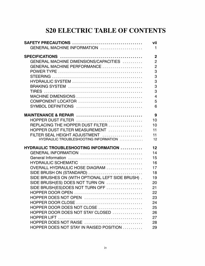
S20 ELECTRIC TABLE OF CONTENTS
SAFETY PRECAUTIONS vii. . . . . . . . . . . . . . . . . . . . . . . . . . . . . . . . . . .GENERAL MACHINE INFORMATION 1. . . . . . . . . . . . . . . . . . . . .
SPECIFICATIONS 2. . . . . . . . . . . . . . . . . . . . . . . . . . . . . . . . . . . . . . . . .GENERAL MACHINE DIMENSIONS/CAPACITIES 2. . . . . . . . . .GENERAL MACHINE PERFORMANCE 2. . . . . . . . . . . . . . . . . . . .POWER TYPE 3. . . . . . . . . . . . . . . . . . . . . . . . . . . . . . . . . . . . . . . . . .STEERING 3. . . . . . . . . . . . . . . . . . . . . . . . . . . . . . . . . . . . . . . . . . . . .HYDRAULIC SYSTEM 3. . . . . . . . . . . . . . . . . . . . . . . . . . . . . . . . . . .BRAKING SYSTEM 3. . . . . . . . . . . . . . . . . . . . . . . . . . . . . . . . . . . . .TIRES 3. . . . . . . . . . . . . . . . . . . . . . . . . . . . . . . . . . . . . . . . . . . . . . . . .MACHINE DIMENSIONS 4. . . . . . . . . . . . . . . . . . . . . . . . . . . . . . . . .COMPONENT LOCATOR 5. . . . . . . . . . . . . . . . . . . . . . . . . . . . . . . .SYMBOL DEFINITIONS 6. . . . . . . . . . . . . . . . . . . . . . . . . . . . . . . . .
MAINTENANCE & REPAIR 9. . . . . . . . . . . . . . . . . . . . . . . . . . . . . . . . .HOPPER DUST FILTER 10. . . . . . . . . . . . . . . . . . . . . . . . . . . . . . . . .REPLACING THE HOPPER DUST FILTER 10. . . . . . . . . . . . . . . . .HOPPER DUST FILTER MEASUREMENT 11. . . . . . . . . . . . . . . . .FILTER SEAL HEIGHT ADJUSTMENT 11. . . . . . . . . . . . . . . . . . . .
HYDRAULIC TROUBLESHOOTING INFORMATION 12. . . . . . . . . . . . . .
HYDRAULIC TROUBLESHOOTING INFORMATION 12. . . . . . . . . . .GENERAL INFORMATION 14. . . . . . . . . . . . . . . . . . . . . . . . . . . . . . .General Information 15. . . . . . . . . . . . . . . . . . . . . . . . . . . . . . . . . . . . .HYDRAULIC SCHEMATIC 16. . . . . . . . . . . . . . . . . . . . . . . . . . . . . . .OVERALL HYDRAULIC HOSE DIAGRAM 17. . . . . . . . . . . . . . . . . .SIDE BRUSH ON (STANDARD) 18. . . . . . . . . . . . . . . . . . . . . . . . . . .SIDE BRUSHES ON (WITH OPTIONAL LEFT SIDE BRUSH) 19.SIDE BRUSH(ES) DOES NOT TURN ON 20. . . . . . . . . . . . . . . . . .SIDE BRUSH(ES)DOES NOT TURN OFF 21. . . . . . . . . . . . . . . . . .HOPPER DOOR OPEN 22. . . . . . . . . . . . . . . . . . . . . . . . . . . . . . . . . .HOPPER DOES NOT OPEN 23. . . . . . . . . . . . . . . . . . . . . . . . . . . . .HOPPER DOOR CLOSE 24. . . . . . . . . . . . . . . . . . . . . . . . . . . . . . . . .HOPPER DOOR DOES NOT CLOSE 25. . . . . . . . . . . . . . . . . . . . . .HOPPER DOOR DOES NOT STAY CLOSED 26. . . . . . . . . . . . . . .HOPPER LIFT 27. . . . . . . . . . . . . . . . . . . . . . . . . . . . . . . . . . . . . . . . . .HOPPER DOES NOT RAISE 28. . . . . . . . . . . . . . . . . . . . . . . . . . . . .HOPPER DOES NOT STAY IN RAISED POSITION 29. . . . . . . . . .
v
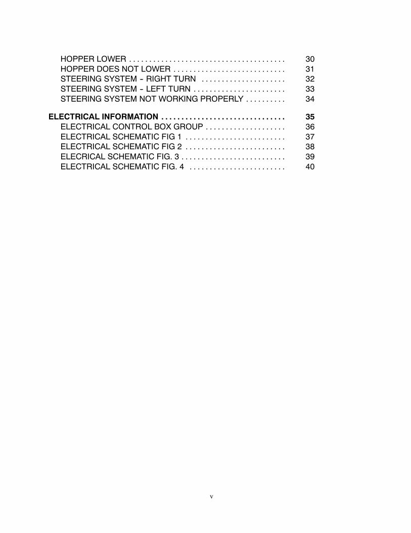
HOPPER LOWER 30. . . . . . . . . . . . . . . . . . . . . . . . . . . . . . . . . . . . . . .HOPPER DOES NOT LOWER 31. . . . . . . . . . . . . . . . . . . . . . . . . . . .STEERING SYSTEM -- RIGHT TURN 32. . . . . . . . . . . . . . . . . . . . .STEERING SYSTEM -- LEFT TURN 33. . . . . . . . . . . . . . . . . . . . . . .STEERING SYSTEM NOT WORKING PROPERLY 34. . . . . . . . . .
ELECTRICAL INFORMATION 35. . . . . . . . . . . . . . . . . . . . . . . . . . . . . . .ELECTRICAL CONTROL BOX GROUP 36. . . . . . . . . . . . . . . . . . . .ELECTRICAL SCHEMATIC FIG 1 37. . . . . . . . . . . . . . . . . . . . . . . . .ELECTRICAL SCHEMATIC FIG 2 38. . . . . . . . . . . . . . . . . . . . . . . . .ELECRICAL SCHEMATIC FIG. 3 39. . . . . . . . . . . . . . . . . . . . . . . . . .ELECTRICAL SCHEMATIC FIG. 4 40. . . . . . . . . . . . . . . . . . . . . . . .

vi
S20 Service Information
viiS20 Electric 9006709 (11--09)
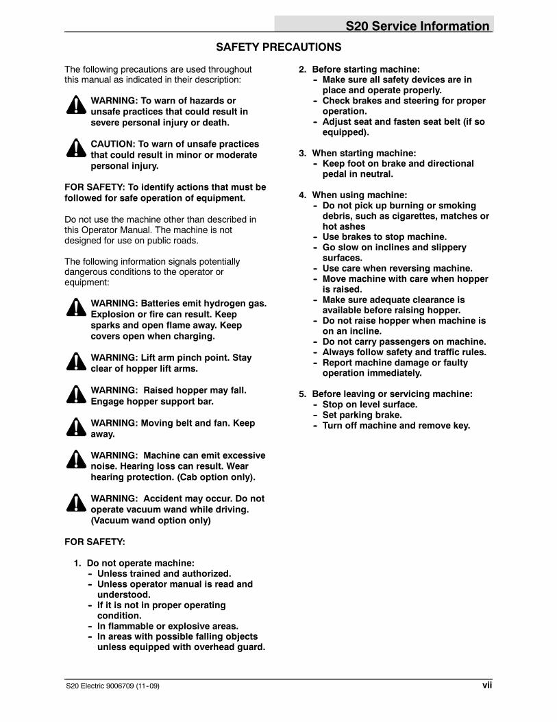
SAFETY PRECAUTIONS
The following precautions are used throughoutthis manual as indicated in their description:
WARNING: To warn of hazards orunsafe practices that could result insevere personal injury or death.
CAUTION: To warn of unsafe practicesthat could result in minor or moderatepersonal injury.
FOR SAFETY: To identify actions that must befollowed for safe operation of equipment.
Do not use the machine other than described inthis Operator Manual. The machine is notdesigned for use on public roads.
The following information signals potentiallydangerous conditions to the operator orequipment:
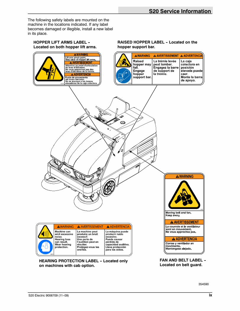
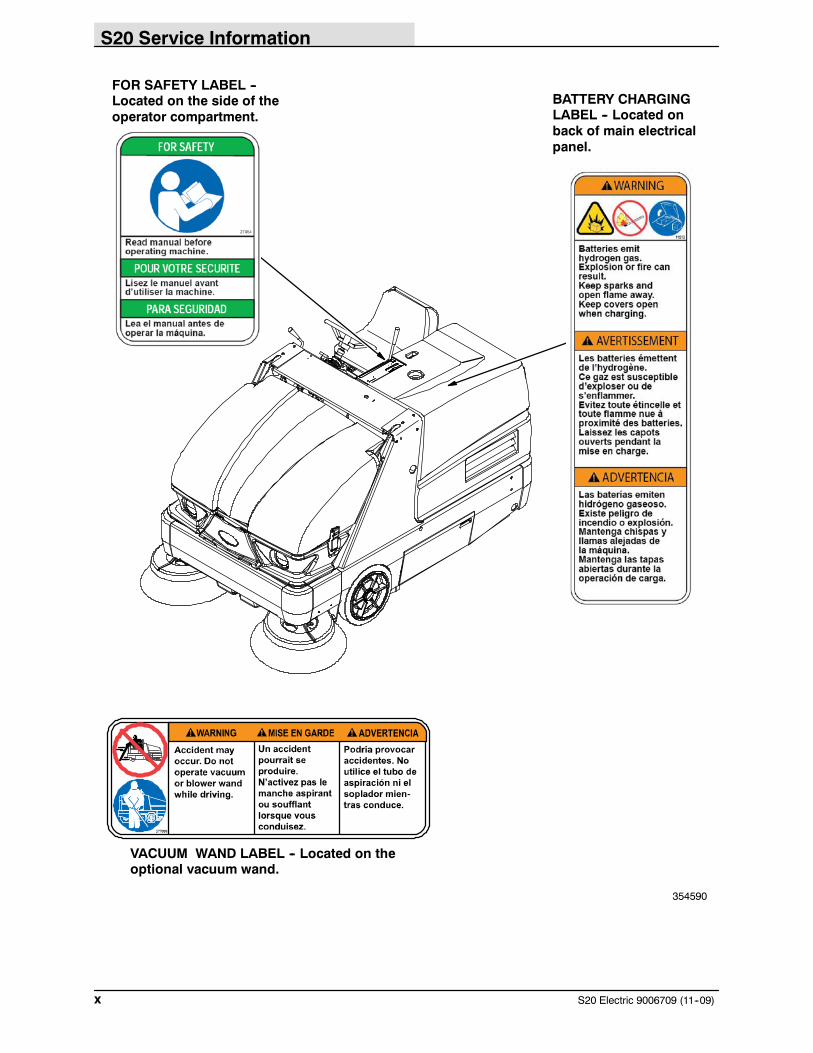
WARNING: Batteries emit hydrogen gas.Explosion or fire can result. Keepsparks and open flame away. Keepcovers open when charging.
WARNING: Lift arm pinch point. Stayclear of hopper lift arms.
WARNING: Raised hopper may fall.Engage hopper support bar.
WARNING: Moving belt and fan. Keepaway.
WARNING: Machine can emit excessivenoise. Hearing loss can result. Wearhearing protection. (Cab option only).
WARNING: Accident may occur. Do notoperate vacuum wand while driving.(Vacuum wand option only)
FOR SAFETY:
1. Do not operate machine:-- Unless trained and authorized.-- Unless operator manual is read andunderstood.
-- If it is not in proper operatingcondition.
-- In flammable or explosive areas.-- In areas with possible falling objectsunless equipped with overhead guard.
2. Before starting machine:-- Make sure all safety devices are inplace and operate properly.
-- Check brakes and steering for properoperation.
-- Adjust seat and fasten seat belt (if soequipped).
3. When starting machine:-- Keep foot on brake and directionalpedal in neutral.
4. When using machine:-- Do not pick up burning or smokingdebris, such as cigarettes, matches orhot ashes
-- Use brakes to stop machine.-- Go slow on inclines and slipperysurfaces.
-- Use care when reversing machine.-- Move machine with care when hopperis raised.
-- Make sure adequate clearance isavailable before raising hopper.
-- Do not raise hopper when machine ison an incline.
-- Do not carry passengers on machine.-- Always follow safety and traffic rules.-- Report machine damage or faultyoperation immediately.
5. Before leaving or servicing machine:-- Stop on level surface.-- Set parking brake.-- Turn off machine and remove key.
S20 Service Information
S20 Electric 9006709 (11--09)viii
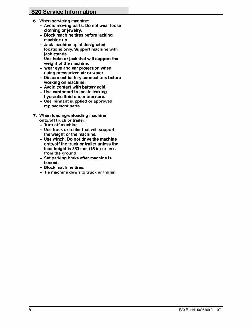
6. When servicing machine:-- Avoid moving parts. Do not wear looseclothing or jewelry.
-- Block machine tires before jackingmachine up.
-- Jack machine up at designatedlocations only. Support machine withjack stands.
-- Use hoist or jack that will support theweight of the machine.
-- Wear eye and ear protection whenusing pressurized air or water.
-- Disconnect battery connections beforeworking on machine.
-- Avoid contact with battery acid.-- Use cardboard to locate leakinghydraulic fluid under pressure.
-- Use Tennant supplied or approvedreplacement parts.
7. When loading/unloading machineonto/off truck or trailer:-- Turn off machine.-- Use truck or trailer that will supportthe weight of the machine.
-- Use winch. Do not drive the machineonto/off the truck or trailer unless theload height is 380 mm (15 in) or lessfrom the ground.
-- Set parking brake after machine isloaded.
-- Block machine tires.-- Tie machine down to truck or trailer.
S20 Service Information
ixS20 Electric 9006709 (11--09)
The following safety labels are mounted on themachine in the locations indicated. If any labelbecomes damaged or illegible, install a new labelin its place.
HOPPER LIFT ARMS LABEL --Located on both hopper lift arms.
FAN AND BELT LABEL --Located on belt guard.
354590
RAISED HOPPER LABEL -- Located on thehopper support bar.
HEARING PROTECTION LABEL -- Located onlyon machines with cab option.
S20 Service Information
S20 Electric 9006709 (11--09)x
BATTERY CHARGINGLABEL -- Located onback of main electricalpanel.
354590
VACUUM WAND LABEL -- Located on theoptional vacuum wand.
FOR SAFETY LABEL --Located on the side of theoperator compartment.
S20 Service Information
1S20 Electric 9006709(11--09)
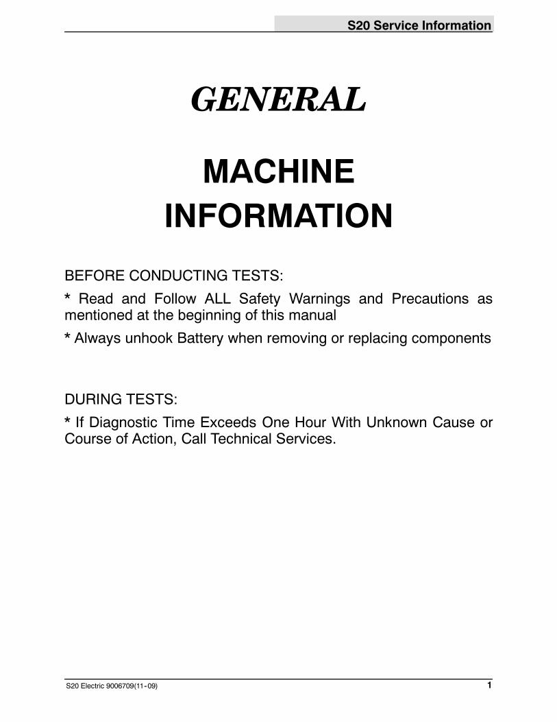
GENERAL
MACHINEINFORMATION
BEFORE CONDUCTING TESTS:
* Read and Follow ALL Safety Warnings and Precautions asmentioned at the beginning of this manual
* Always unhook Battery when removing or replacing components
DURING TESTS:
* If Diagnostic Time Exceeds One Hour With Unknown Cause orCourse of Action, Call Technical Services.
S20 Service Information
S20 Electric 9006709 (11--09)2
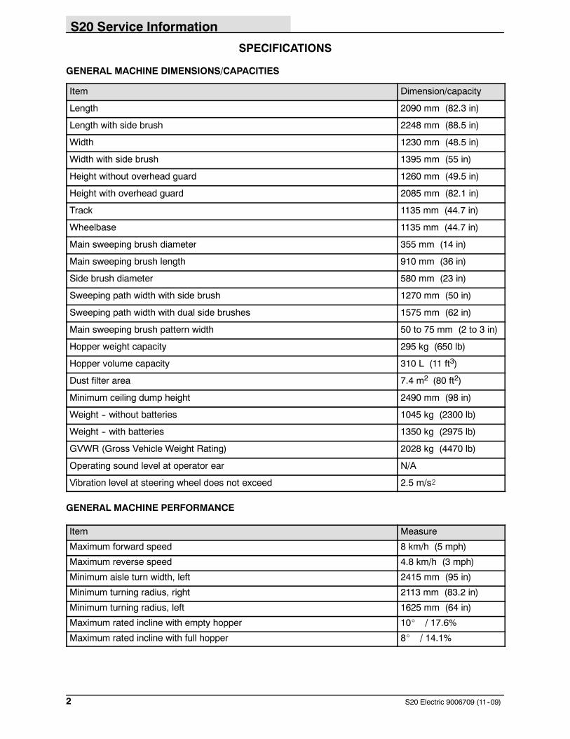
SPECIFICATIONS
GENERAL MACHINE DIMENSIONS/CAPACITIES
Item Dimension/capacity
Length 2090 mm (82.3 in)
Length with side brush 2248 mm (88.5 in)
Width 1230 mm (48.5 in)
Width with side brush 1395 mm (55 in)
Height without overhead guard 1260 mm (49.5 in)
Height with overhead guard 2085 mm (82.1 in)
Track 1135 mm (44.7 in)
Wheelbase 1135 mm (44.7 in)
Main sweeping brush diameter 355 mm (14 in)
Main sweeping brush length 910 mm (36 in)
Side brush diameter 580 mm (23 in)
Sweeping path width with side brush 1270 mm (50 in)
Sweeping path width with dual side brushes 1575 mm (62 in)
Main sweeping brush pattern width 50 to 75 mm (2 to 3 in)
Hopper weight capacity 295 kg (650 lb)
Hopper volume capacity 310 L (11 ft3)
Dust filter area 7.4 m2 (80 ft2)
Minimum ceiling dump height 2490 mm (98 in)
Weight -- without batteries 1045 kg (2300 lb)
Weight -- with batteries 1350 kg (2975 lb)
GVWR (Gross Vehicle Weight Rating) 2028 kg (4470 lb)
Operating sound level at operator ear N/A
Vibration level at steering wheel does not exceed 2.5 m/s@
GENERAL MACHINE PERFORMANCE
Item Measure
Maximum forward speed 8 km/h (5 mph)
Maximum reverse speed 4.8 km/h (3 mph)
Minimum aisle turn width, left 2415 mm (95 in)
Minimum turning radius, right 2113 mm (83.2 in)
Minimum turning radius, left 1625 mm (64 in)
Maximum rated incline with empty hopper 10_ / 17.6%
Maximum rated incline with full hopper 8_ / 14.1%
S20 Service Information
3S20 Electric 9006709(11--09)
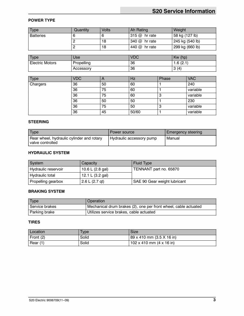
POWER TYPE
Type Quantity Volts Ah Rating WeightBatteries 6 6 315 @ hr rate 58 kg (127 lb)
2 18 340 @ hr rate 245 kg (540 lb)2 18 440 @ hr rate 299 kg (660 lb)
Type Use VDC Kw (hp)Electric Motors Propelling 36 1.6 (2.1)
Accessory 36 3 (4)
Type VDC A Hz Phase VACChargers 36 50 60 1 240
36 75 60 1 variable36 75 60 3 variable36 50 50 1 23036 75 50 3 variable36 45 50/60 1 variable
STEERING
Type Power source Emergency steering
Rear wheel, hydraulic cylinder and rotaryvalve controlled
Hydraulic accessory pump Manual
HYDRAULIC SYSTEM
System Capacity Fluid Type
Hydraulic reservoir 10.6 L (2.8 gal) TENNANT part no. 65870
Hydraulic total 12.1 L (3.2 gal)
Propelling gearbox 2.6 L (2.7 qt) SAE 90 Gear weight lubricant
BRAKING SYSTEM
Type OperationService brakes Mechanical drum brakes (2), one per front wheel, cable actuatedParking brake Utilizes service brakes, cable actuated
TIRES
Location Type SizeFront (2) Solid 89 x 410 mm (3.5 X 16 in)Rear (1) Solid 102 x 410 mm (4 x 16 in)
S20 Service Information
S20 Electric 9006709 (11--09)4
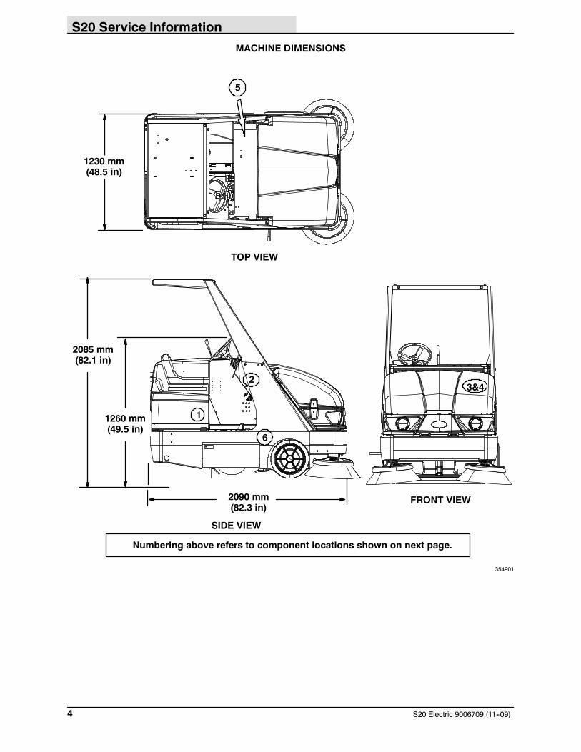
MACHINE DIMENSIONS
TOP VIEW
SIDE VIEW
2090 mm(82.3 in)
1230 mm(48.5 in)
2085 mm(82.1 in)
FRONT VIEW
1260 mm(49.5 in)
1
23&4
6
Numbering above refers to component locations shown on next page.
5
354901
S20 Service Information
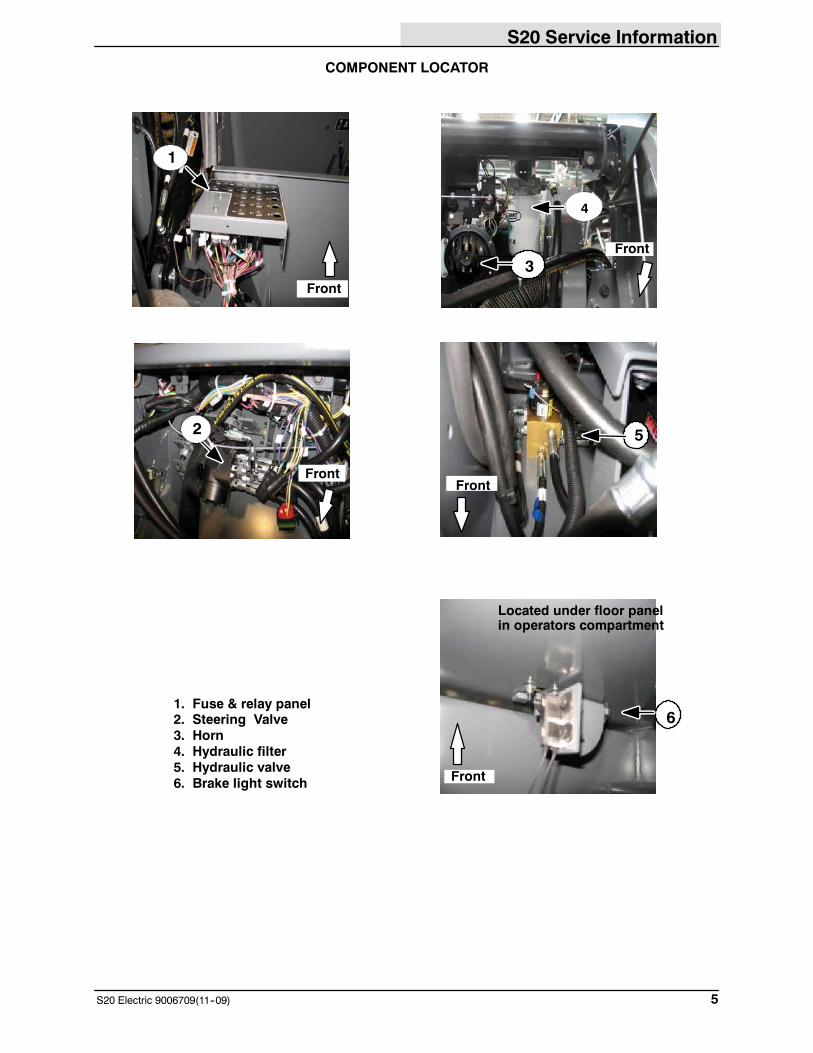
5S20 Electric 9006709(11--09)
COMPONENT LOCATOR
1
1. Fuse & relay panel2. Steering Valve3. Horn4. Hydraulic filter5. Hydraulic valve6. Brake light switch
3
5
6
Located under floor panelin operators compartment
2
Front
FrontFront
Front
Front
4
4
S20 Service Information
S20 Electric 9006709 (11--09)6
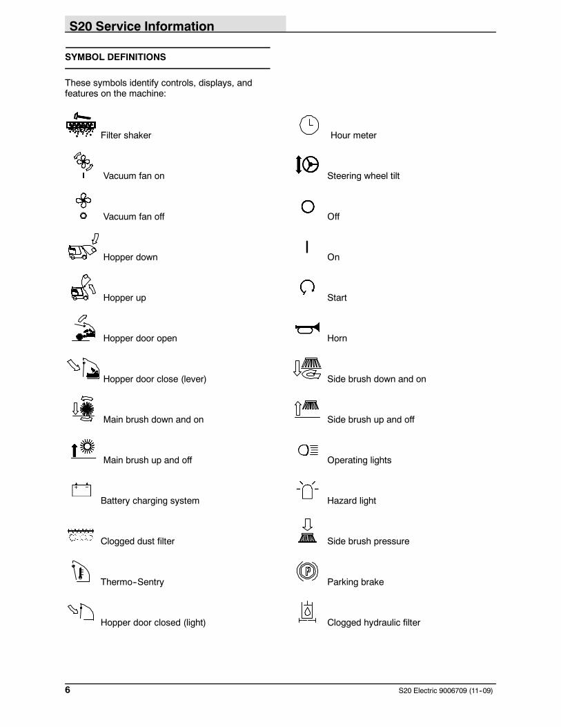
SYMBOL DEFINITIONS
These symbols identify controls, displays, andfeatures on the machine:
Filter shaker Hour meter
Vacuum fan on Steering wheel tilt
Vacuum fan off Off
Hopper down On
Hopper up Start
Hopper door open Horn
Hopper door close (lever) Side brush down and on
Main brush down and on Side brush up and off
Main brush up and off Operating lights
Battery charging system Hazard light
Clogged dust filter Side brush pressure
Thermo--Sentry Parking brake
Hopper door closed (light) Clogged hydraulic filter
S20 Service Information
7S20 Electric 9006709(11--09)
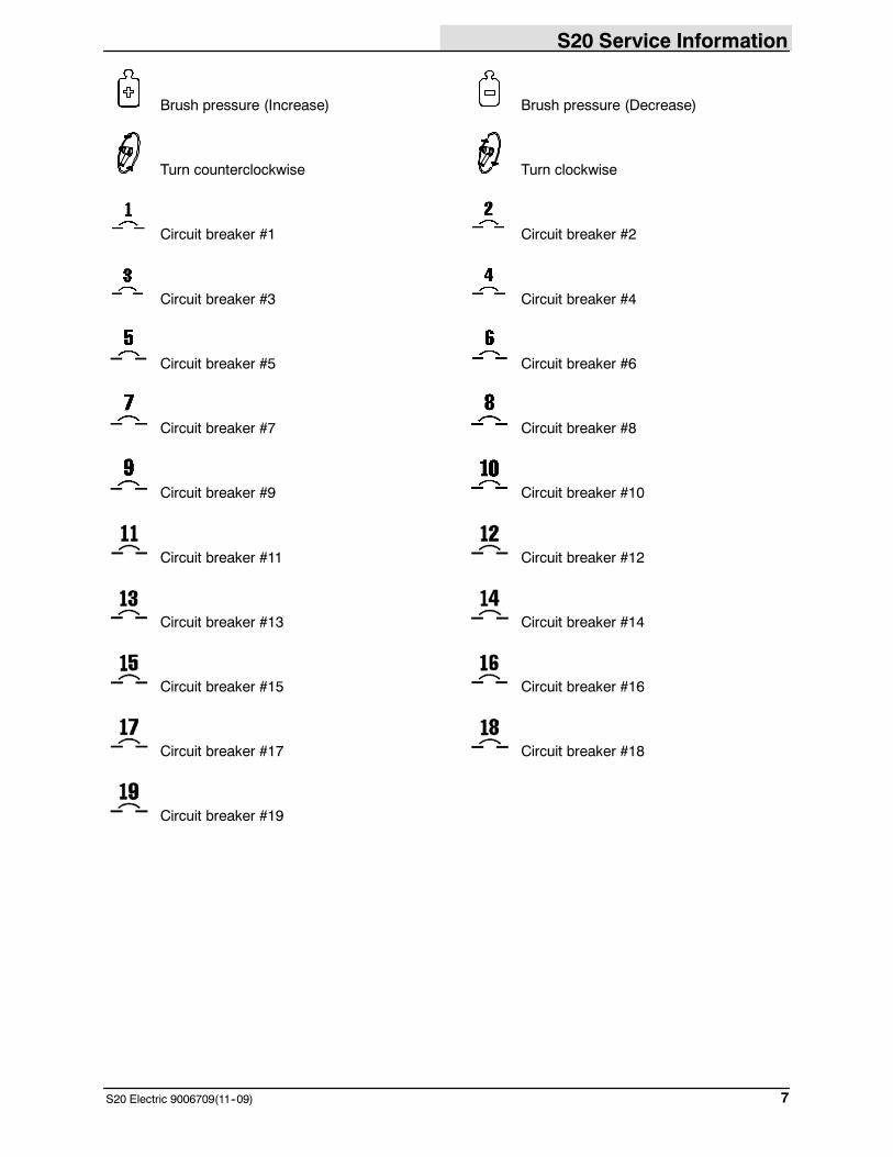
Brush pressure (Increase) Brush pressure (Decrease)
Turn counterclockwise Turn clockwise
Circuit breaker #1 Circuit breaker #2
Circuit breaker #3 Circuit breaker #4
Circuit breaker #5 Circuit breaker #6
Circuit breaker #7 Circuit breaker #8
Circuit breaker #9 Circuit breaker #10
Circuit breaker #11 Circuit breaker #12
Circuit breaker #13 Circuit breaker #14
Circuit breaker #15 Circuit breaker #16
Circuit breaker #17 Circuit breaker #18
Circuit breaker #19

S20 Service Information
S20 Electric 9006709 (11--09)8
FOR OPERATOR AND MAINTENANCE CHARTS, REFER TO OPERATORS MANUAL.
S20 Service Information
9S20 Electric 9006709 (11--09)
MAINTENANCE& REPAIR
BEFORE CONDUCTING TESTS:
* Read and Follow ALL Safety Warnings and Precautions asmentioned at the beginning of this manual* Always unhook Battery when removing or replacing electricalcomponents
DURING TESTS:
* If Diagnostic Time Exceeds One Hour With Unknown Cause orCourse of Action, Call Technical Services.
S20 Service Information
10 S20 Electric 9006709 (11--09)
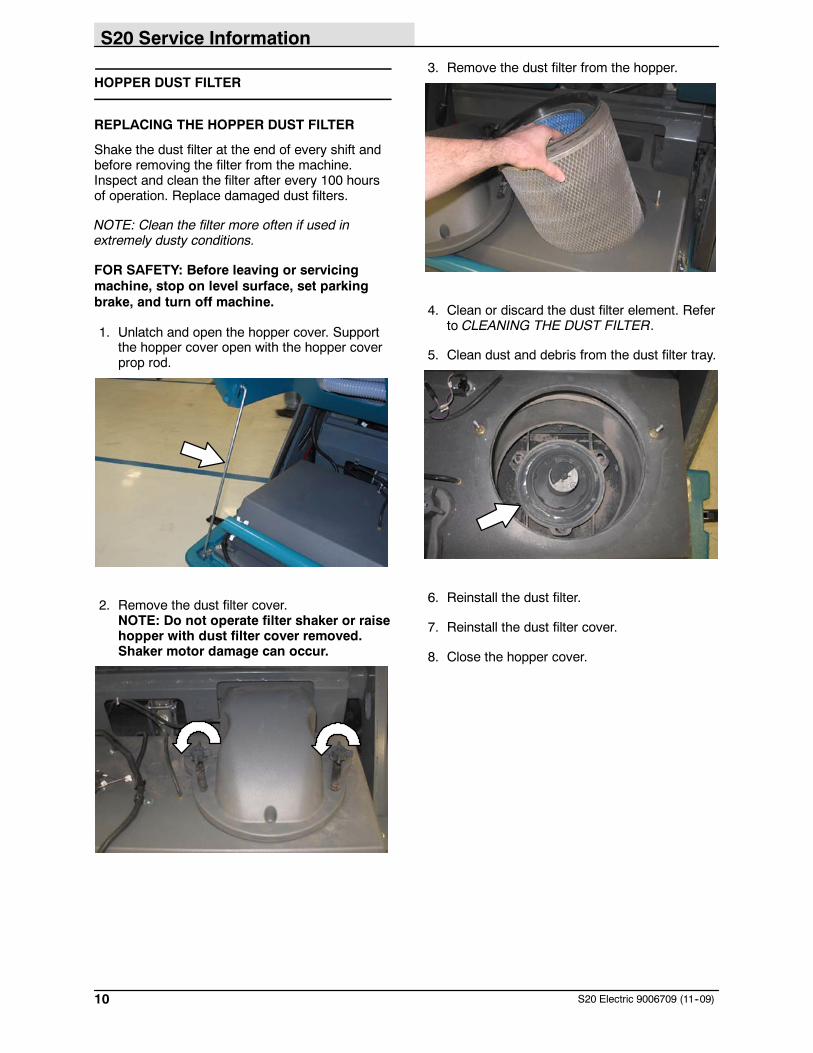
HOPPER DUST FILTER
REPLACING THE HOPPER DUST FILTER
Shake the dust filter at the end of every shift andbefore removing the filter from the machine.Inspect and clean the filter after every 100 hoursof operation. Replace damaged dust filters.
NOTE: Clean the filter more often if used inextremely dusty conditions.
FOR SAFETY: Before leaving or servicingmachine, stop on level surface, set parkingbrake, and turn off machine.
1. Unlatch and open the hopper cover. Supportthe hopper cover open with the hopper coverprop rod.
2. Remove the dust filter cover.NOTE: Do not operate filter shaker or raisehopper with dust filter cover removed.Shaker motor damage can occur.
3. Remove the dust filter from the hopper.
4. Clean or discard the dust filter element. Referto CLEANING THE DUST FILTER.
5. Clean dust and debris from the dust filter tray.
6. Reinstall the dust filter.
7. Reinstall the dust filter cover.
8. Close the hopper cover.
S20 Service Information
11S20 Electric 9006709 (11--09)
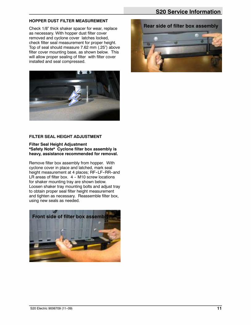
HOPPER DUST FILTER MEASUREMENT
Check 1/8” thick shaker spacer for wear, replaceas necessary. With hopper dust filter coverremoved and cyclone cover latches locked,check filter seal measurement for proper height.Top of seal should measure 7.62 mm (.25”) abovefilter cover mounting base, as shown below. Thiswill allow proper sealing of filter with filter coverinstalled and seal compressed.
FILTER SEAL HEIGHT ADJUSTMENT
Filter Seal Height Adjustment*Safety Note* Cyclone filter box assembly isheavy, assistance recommended for removal.
Remove filter box assembly from hopper. Withcyclone cover in place and latched, mark sealheight measurement at 4 places; RF--LF--RR--andLR areas of filter box. 4 -- M10 screw locationsfor shaker mounting tray are shown below.Loosen shaker tray mounting bolts and adjust trayto obtain proper seal filter height measurementand tighten as necessary. Reassemble filter box,using new seals as needed.
Front side of filter box assembly
Rear side of filter box assembly
S20 Service Information
12 S20 Electric 9006709 (11--09)
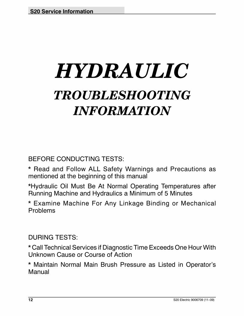
HYDRAULICTROUBLESHOOTING
INFORMATION
BEFORE CONDUCTING TESTS:
* Read and Follow ALL Safety Warnings and Precautions asmentioned at the beginning of this manual
*Hydraulic Oil Must Be At Normal Operating Temperatures afterRunning Machine and Hydraulics a Minimum of 5 Minutes
* Examine Machine For Any Linkage Binding or MechanicalProblems
DURING TESTS:
* Call Technical Services if Diagnostic Time ExceedsOneHourWithUnknown Cause or Course of Action
* Maintain Normal Main Brush Pressure as Listed in Operator’sManual
S20 Service Information
13S20 Electric 9006709 (11--09)
NOTE: Troubleshooting charts may be shown with optional equipment. The optionalequipmentmay not be specified in these charts. Somemachinesmay not be equippedwithall components shown.
S20 Service Information
14 S20 Electric 9006709 (11--09)
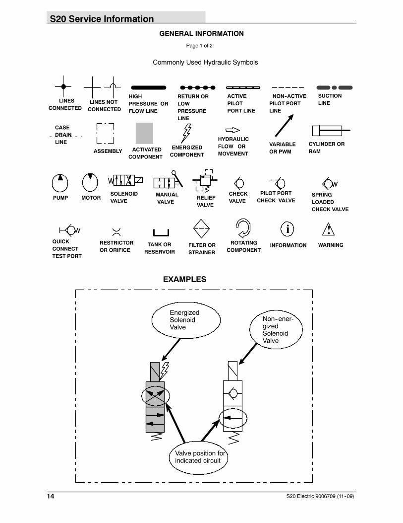
GENERAL INFORMATION
Page 1 of 2
Commonly Used Hydraulic Symbols
i
LINES NOTCONNECTED
ASSEMBLYCYLINDER ORRAMACTIVATED
COMPONENT
ENERGIZEDCOMPONENT
INFORMATION
HIGHPRESSURE ORFLOW LINE
RETURN ORLOWPRESSURELINE
NON--ACTIVEPILOT PORTLINE
!WARNING
LINESCONNECTED
SUCTIONLINE
ACTIVEPILOTPORT LINE
CASEDRAINLINE HYDRAULIC
FLOW ORMOVEMENT
VARIABLEOR PWM
ROTATINGCOMPONENT
PUMP MOTORSOLENOIDVALVE
MANUALVALVE
RELIEFVALVE
CHECKVALVE
PILOT PORTCHECK VALVE
SPRINGLOADEDCHECK VALVE
QUICKCONNECTTEST PORT
RESTRICTOROR ORIFICE
TANK ORRESERVOIR
FILTER ORSTRAINER
EnergizedSolenoidValve
Non--ener-gizedSolenoidValve
Valve position forindicated circuit
EXAMPLES
S20 Service Information
15S20 Electric 9006709 (11--09)
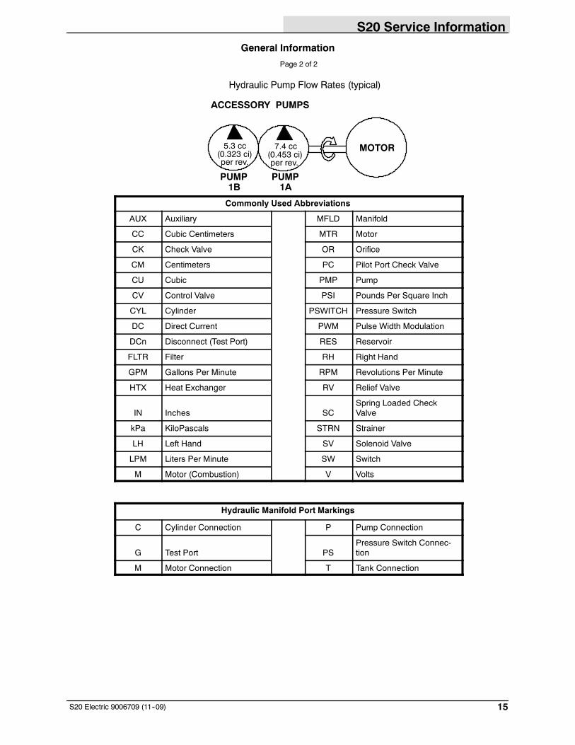
General Information
Page 2 of 2
Hydraulic Pump Flow Rates (typical)
ACCESSORY PUMPS
7.4 cc
per rev.(0.453 ci)
5.3 cc
per rev.(0.323 ci)
PUMP1B
PUMP1A
MOTOR
Commonly Used Abbreviations
AUX Auxiliary MFLD Manifold
CC Cubic Centimeters MTR Motor
CK Check Valve OR Orifice
CM Centimeters PC Pilot Port Check Valve
CU Cubic PMP Pump
CV Control Valve PSI Pounds Per Square Inch
CYL Cylinder PSWITCH Pressure Switch
DC Direct Current PWM Pulse Width Modulation
DCn Disconnect (Test Port) RES Reservoir
FLTR Filter RH Right Hand
GPM Gallons Per Minute RPM Revolutions Per Minute
HTX Heat Exchanger RV Relief Valve
IN Inches SCSpring Loaded CheckValve
kPa KiloPascals STRN Strainer
LH Left Hand SV Solenoid Valve
LPM Liters Per Minute SW Switch
M Motor (Combustion) V Volts
Hydraulic Manifold Port Markings
C Cylinder Connection P Pump Connection
G Test Port PSPressure Switch Connec-tion
M Motor Connection T Tank Connection
S20 Service Information
16 S20 Electric 9006709 (11--09)
HYDRAULIC SCHEMATIC
S20 Service Information
17S20 Electric 9006709 (11--09)
OVERALL HYDRAULIC HOSE DIAGRAM
BPB
C3
A
T
P1
P2
RL
T
BYDCD
B
AIN
OUT
P
INOUT
1
2
2
3
45
6
7
89
10
11
12
13
14
15
16
17
18
RESERVOIR
S20 Service Information
18 S20 Electric 9006709 (11--09)
SIDE BRUSH ON (STANDARD)Conditions: Key ON, Side Brush Lowered
RESERVOIR
STRN1
P1
G1
P
89.6 BAR
(1300psi)
T
SV1
(50 psi)
FLTR
PB
3.4 BAR
PRESSURE
2.8 BAR (40 psi)SWITCH
B
MTR1
T
(1.4 GPM)5.2 LPM
PRESSURE READINGS
BASED ON HYDRAULIC OIL
TEMPERATURE OF 65.5_C
(150_F)
i
RIGHT SIDEBRUSH MOTOR
85 RPM +/-- 10 RPM
15.5 BAR (225 PSI)CV8
SOLENOIDVALVE
MANIFOLD
G2
PUMP
1B
PUMP
1A
P2
MOTOR
@ 1000 RPM
TO CV2 HOPPERVALVEMANIFOLD
STEERING
VALVE
ASSEMBLYCV3
(1.9 GPM)
7.3 LPM
62 BAR
RV1
(900 psi)
RV2
TEST PORT15.5 BAR(225 PSI)
TEST PORT15.5 BAR(225 PSI)
A
TURNS PUMPS
CK1
12.5 LPM (3.3 GPM)
MOTOR
RV4
S20 Service Information
19S20 Electric 9006709 (11--09)
SIDE BRUSHES ON (WITH OPTIONAL LEFT SIDE BRUSH)
Conditions: Key ON, Side Brushes Lowered
RESERVOIR
STRN1
P1
G1
P
89.6 BAR(1300 psi)
T
SV1
(50 psi)
FLTR
PB
3.4 BAR
PRESSURE
2.8 BAR(40 psi)
SWITCH
B
MTR1
T
PRESSUREREADINGS BASED ONHYDRAULIC OILTEMPERATURE OF65.5_C (150_F)
i
RIGHT SIDE
BRUSH MOTOR85 RPM +/-- 10 RPM
CV8SOLENOIDVALVE
MANIFOLD
G2
P2
TO CV2 HOPPERVALVE MANIFOLD
STEERINGVALVEASSEMBLY
CV3
62 BAR
RV1
(900 psi)
RV2
TEST PORT
TEST PORT
AMTR2
LEFT SIDE
BRUSH MOTOR85 RPM +/-- 10 RPM
SV3
C1
C2
LEFT SIDE BRUSHCYL4
LIFT/LOWER
CYLINDER
LOWER
31 BAR
(450 PSI)(450 PSI) 31 BAR
CK1
(1.4 GPM)5.2 LPM
PUMP1B
PUMP 1AMOTOR
@ 1000 RPM
(1.9 GPM)7.3 LPM
TURNS PUMPS
OR1
(0.035 in)0.89 mm
31 BAR (450 PSI)
12.5 LPM (3.3 GPM)
15.5 BAR (225 PSI)
12.5 LPM (3.3 GPM)
MOTOR
RV4
S20 Service Information
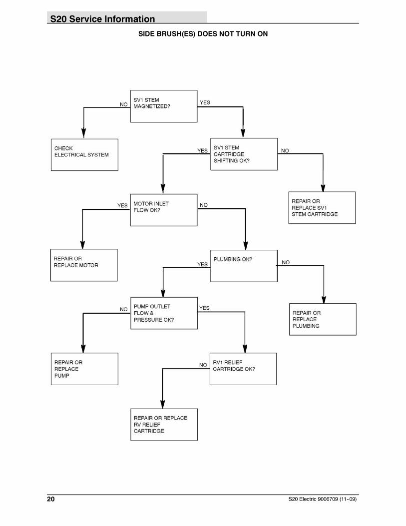
20 S20 Electric 9006709 (11--09)
SIDE BRUSH(ES) DOES NOT TURN ON
S20 Service Information
21S20 Electric 9006709 (11--09)
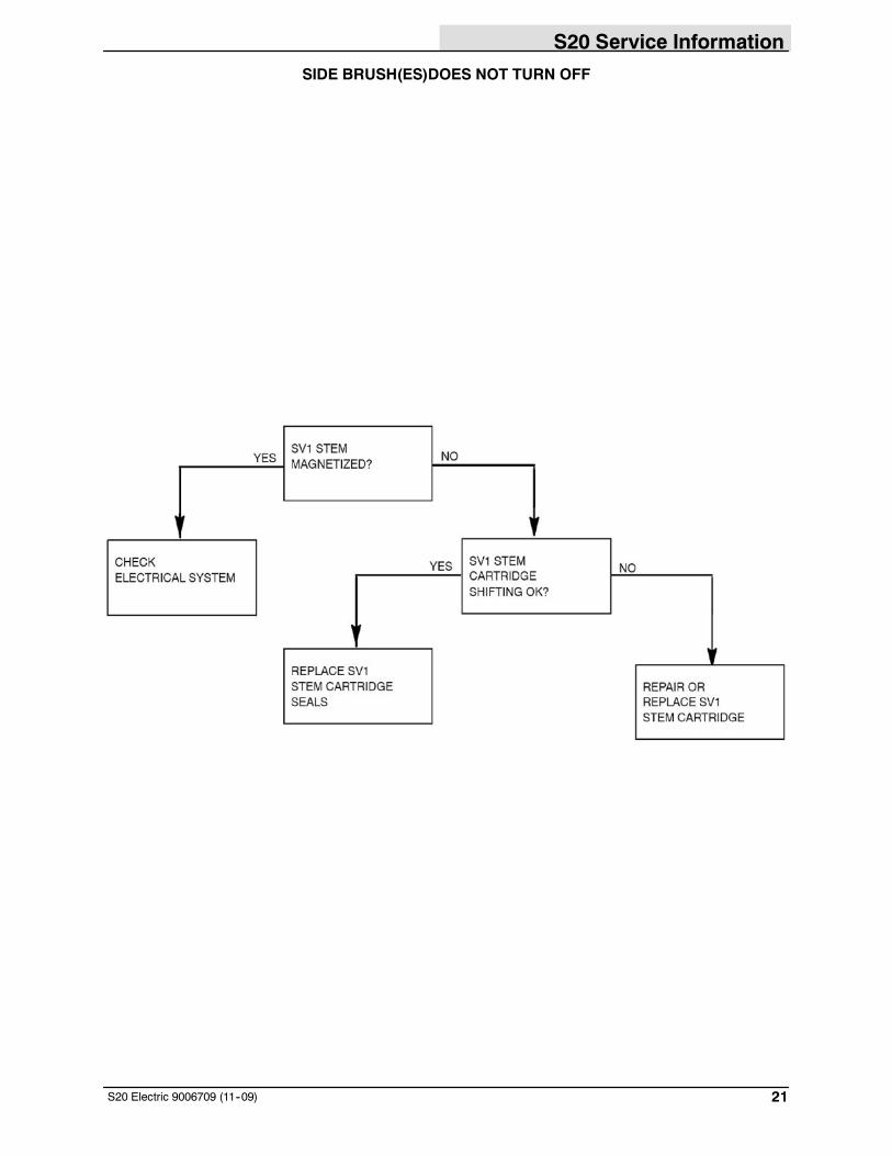
SIDE BRUSH(ES)DOES NOT TURN OFF
S20 Service Information
22 S20 Electric 9006709 (11--09)
HOPPER DOOR OPEN
RESERVOIR
STRN1
(50 psi)3.4 BAR
PRESSURE
2.8 BAR (40 psi)SWITCH
G1
89.6 BAR(1300 psi)
T
PB
BCV8
SOLENOIDVALVE
MANIFOLD
G2
62 BAR(900 psi)
RV2
TESTPORT
TESTPORT
A
CK1
(1.4 GPM)5.2 LPM
PUMP1B
PUMP1A
MOTOR
@ 1000 RPM
(1.9 GPM)7.3 LPM
TURNS PUMPS
PRESSURE READINGS BASED
ON HYDRAULIC OIL
TEMPERATURE OF 65.5_C
(150_F)
i
PT
STEERINGVALVE ASSEMBLYCV3
TO MTR1 SIDEBRUSH MOTOR
TO CYL2 HOPPERLIFT CYLINDER
OPEN
HOPPER
CYLINDERDOOR
OUT BYD
A
B
C
D
CK2
CK3
IN
CYL1
CV2
VALVEMANIFOLD
HOPPER
HOPPERLIFT
HOPPERDOOR
C3
RV1
SV1
P2
P1
P1 RV4
FLTR
S20 Service Information
23S20 Electric 9006709 (11--09)
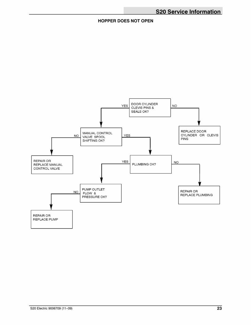
HOPPER DOES NOT OPEN
S20 Service Information
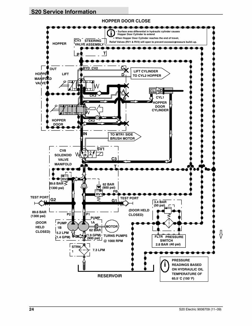
24 S20 Electric 9006709 (11--09)
HOPPER DOOR CLOSE
RESERVOIR
STRN1
(50 psi)3.4 BAR
PRESSURE
2.8 BAR (40 psi)SWITCH
G1
89.6 BAR(1300 psi)
T
PB
CV8SOLENOIDVALVE
MANIFOLD
G2
62 BAR(900 psi)
RV2
TEST PORTTEST PORT
A
CK1
(1.4 GPM)5.2 LPM
PUMP1B
PUMP1A
MOTOR
@ 1000 RPM
(1.9 GPM)
7.3 LPM
TURNS PUMPS
PRESSUREREADINGS BASEDON HYDRAULIC OILTEMPERATURE OF65.5_C (150_F)
i
P T
STEERINGVALVE ASSEMBLYCV3
TO MTR1 SIDEBRUSH MOTOR
TO CYL2 HOPPERLIFT CYLINDER
OUT BYD
A
B
C
D
CK2
CK3
IN
CV2
VALVEMANIFOLD
HOPPER
HOPPER LIFT
HOPPERDOOR
C3
RV1
CLOSE
i -- Surface area differential in hydraulic cylinder causes
-- When Hopper Door Cylinder reaches the end of travel,
Hopper Door Cylinder to extend
Relief Valves (RV1 & RV2) will open to prevent excessivepressure build--up.
62 BAR
(900 psi)
89.6 BAR(1300 psi)
(DOORHELDCLOSED)
(DOOR HELDCLOSED)
HOPPER
CYLINDERDOOR
CYL1
SV1
P2 P1
B
FLTR
S20 Service Information
25S20 Electric 9006709 (11--09)
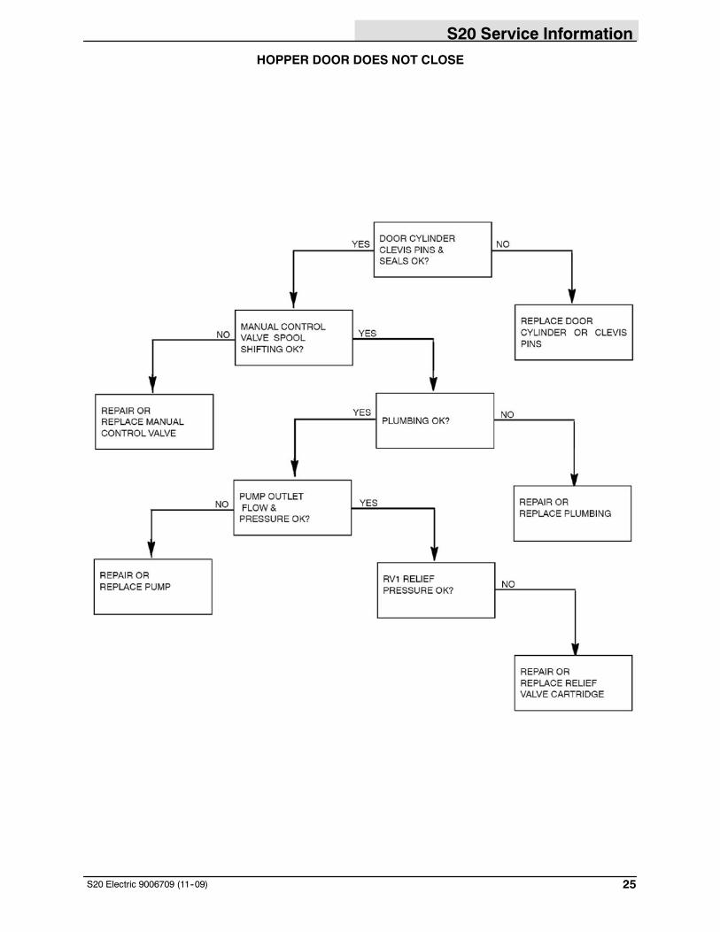
HOPPER DOOR DOES NOT CLOSE
S20 Service Information
26 S20 Electric 9006709 (11--09)
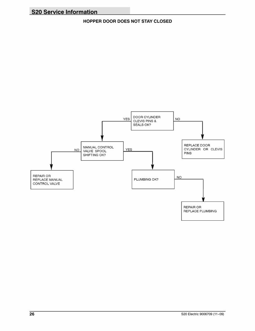
HOPPER DOOR DOES NOT STAY CLOSED
S20 Service Information
27S20 Electric 9006709 (11--09)
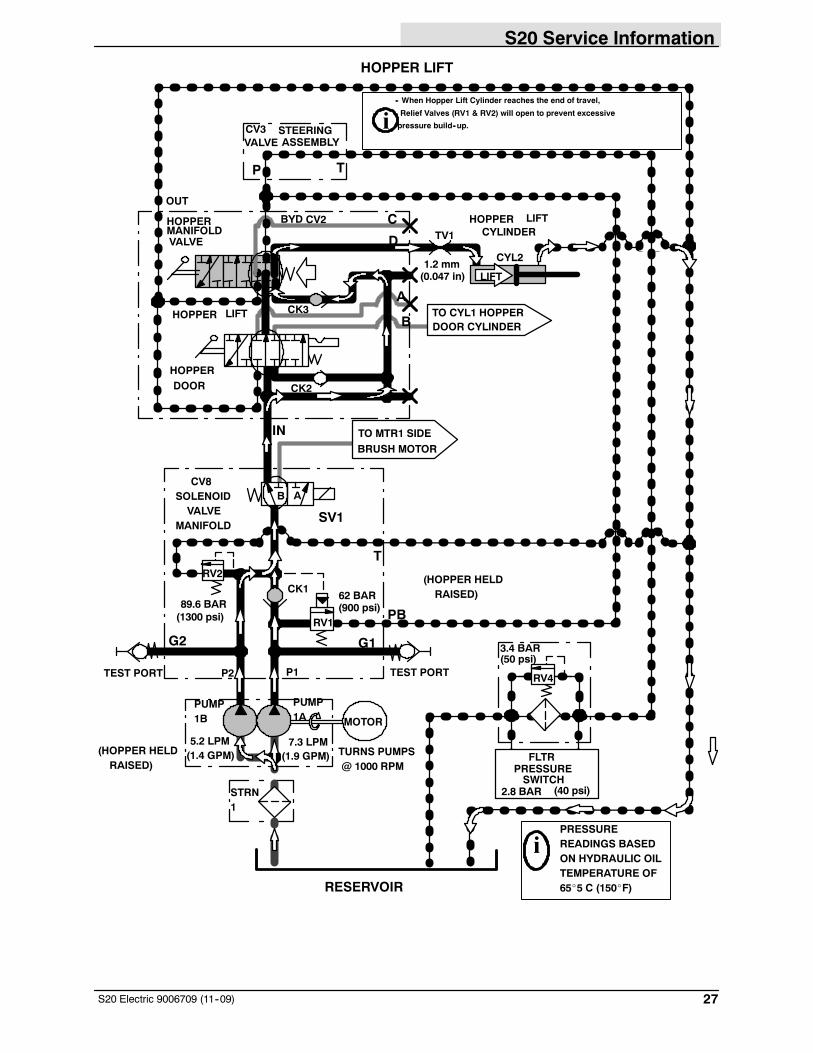
HOPPER LIFT
RESERVOIR
STRN1
(50 psi)3.4 BAR
PRESSURE
2.8 BAR (40 psi)SWITCH
G1
89.6 BAR(1300 psi)
T
PB
CV8SOLENOIDVALVE
MANIFOLD
G2
62 BAR(900 psi)
RV2
TEST PORTTEST PORT
CK1
(1.4 GPM)5.2 LPM
PUMP1B
PUMP1A MOTOR
@ 1000 RPM(1.9 GPM)7.3 LPM
TURNS PUMPS
PRESSUREREADINGS BASEDON HYDRAULIC OILTEMPERATURE OF65_5 C (150_F)
i
P T
STEERINGVALVE ASSEMBLYCV3
TO MTR1 SIDEBRUSH MOTOR
TO CYL1 HOPPERDOOR CYLINDER
HOPPERCYLINDER
LIFT
OUT
BYD
A
B
C
D
CK2
CK3
IN
CYL2
CV2
VALVEMANIFOLDHOPPER
HOPPER LIFT
HOPPERDOOR
RV4
RV1
LIFT
i-- When Hopper Lift Cylinder reaches the end of travel,
Relief Valves (RV1 & RV2) will open to prevent excessive
pressure build--up.
(HOPPER HELDRAISED)
TV1
(0.047 in)1.2 mm
(HOPPER HELDRAISED)
SV1
B A
P2 P1
FLTR
S20 Service Information
28 S20 Electric 9006709 (11--09)
HOPPER DOES NOT RAISE
S20 Service Information
29S20 Electric 9006709 (11--09)
HOPPER DOES NOT STAY IN RAISED POSITION
S20 Service Information
30 S20 Electric 9006709 (11--09)
HOPPER LOWER
RESERVOIR
STRN1
(50 psi)3.4 BARG1
89.6 BAR(1300 psi)
T
PB
CV8SOLENOIDVALVE
MANIFOLD
G2
62 BAR(900 psi)
RV2
TEST PORT
TEST PORT
A
CK1
(1.4 GPM)5.2 LPM
PUMP
1B
PUMP
1A MOTOR
@ 1000 RPM(1.9 GPM)7.3 LPM
TURNS PUMPS
PRESSUREREADINGS BASEDON HYDRAULIC OILTEMPERATURE OF65.5_C (150_F)
i
P T
STEERINGVALVE
ASSEMBLYCV3
TO MTR1 SIDEBRUSH MOTOR
TO CYL1 HOPPERDOOR CYLINDER
HOPPER
CYLINDER
LIFTOUT BYD
A
B
C
D
CK2
CK3
IN
CYL2
CV2
VALVEMANIFOLD
HOPPER
HOPPERLOWER
HOPPERDOOR
RV4
RV1
LOWER
TV1(0.047 in)1.2 mm
Lowering of hopper is dueto gravity (weight of hop-per)
i
SV1B
P1P2
FLTR PRESSURESWITCH
2.8 BAR (40 psi)
S20 Service Information
31S20 Electric 9006709 (11--09)
HOPPER DOES NOT LOWER
S20 Service Information
32 S20 Electric 9006709 (11--09)
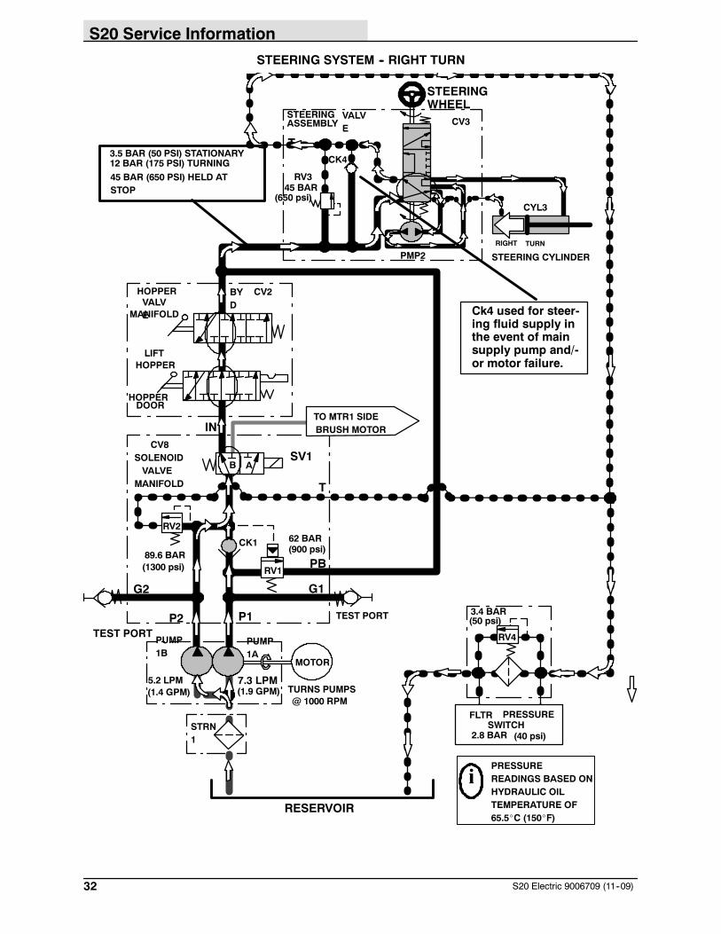
STEERING SYSTEM -- RIGHT TURN
RESERVOIR
STRN1
(50 psi)3.4 BARP1
G1
89.6 BAR(1300 psi)
T
PB
CV8SOLENOIDVALVE
MANIFOLD
G2
P2
62 BAR(900 psi)
RV2
TEST PORT
TEST PORT
A
CK1
(1.4 GPM)5.2 LPM
PUMP1B
PUMP1A
MOTOR
@ 1000 RPM(1.9 GPM)7.3 LPM
TURNS PUMPS
PRESSUREREADINGS BASED ONHYDRAULIC OILTEMPERATURE OF65.5_C (150_F)
i
TO MTR1 SIDEBRUSH MOTOR
BYD
IN
CV2VALVEMANIFOLD
HOPPER
HOPPERLIFT
HOPPERDOOR
RV4
STEERING VALVEASSEMBLY CV3
RIGHT TURNP
T
RV1
STEERING CYLINDER
STEERINGWHEEL
CK4
45 BARRV3
(650 psi)
PMP2
CYL3
45 BAR (650 PSI) HELD ATSTOP
12 BAR (175 PSI) TURNING3.5 BAR (50 PSI) STATIONARY
SV1B
FLTR PRESSURESWITCH
2.8 BAR (40 psi)
Ck4 used for steer-ing fluid supply inthe event of mainsupply pump and/-or motor failure.
S20 Service Information
33S20 Electric 9006709 (11--09)
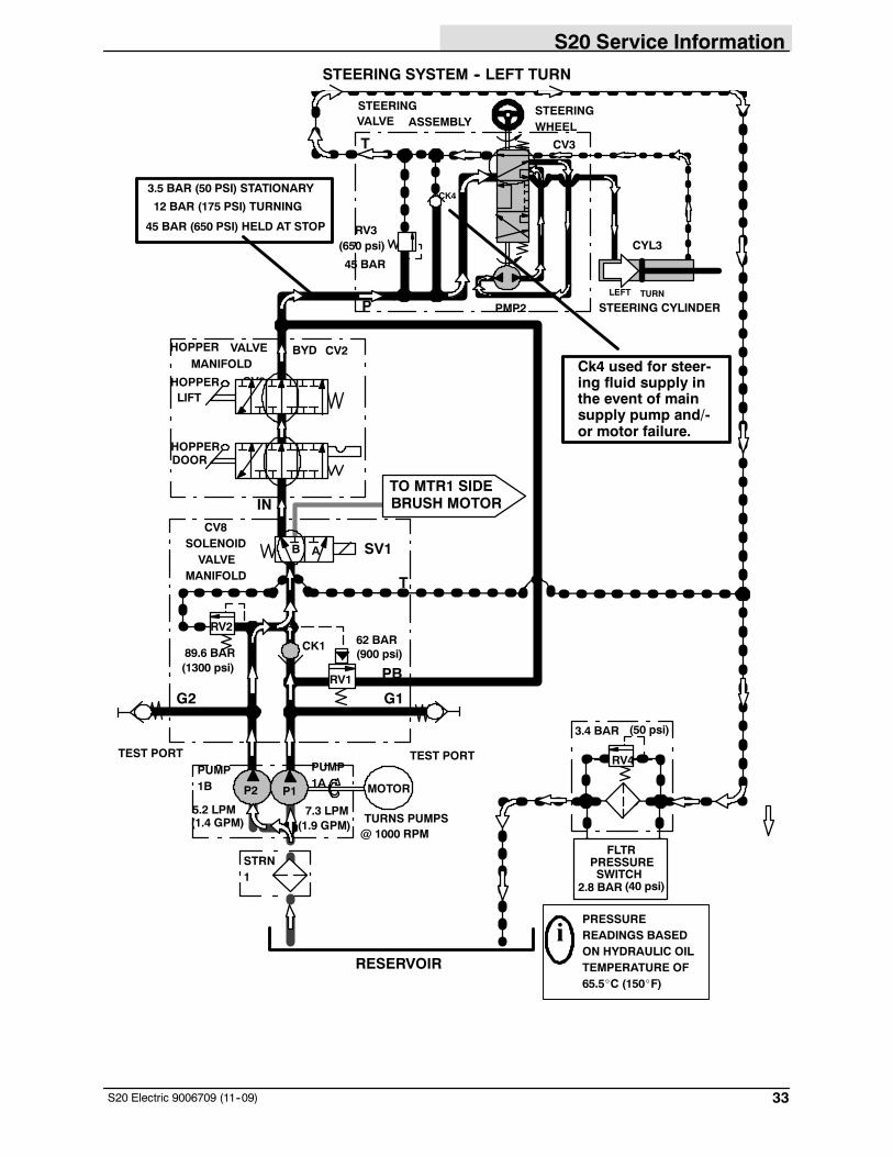
STEERING SYSTEM -- LEFT TURN
RESERVOIR
STRN1
(50 psi)3.4 BAR
PRESSURE
2.8 BAR (40 psi)SWITCH
G1
89.6 BAR(1300 psi)
T
PB
B
CV8SOLENOIDVALVE
MANIFOLD
G2
62 BAR(900 psi)
RV2
TEST PORTTEST PORT
A
CK1
(1.4 GPM)5.2 LPM
PUMP1B
PUMP1A MOTOR
@ 1000 RPM(1.9 GPM)7.3 LPM
TURNS PUMPS
PRESSUREREADINGS BASEDON HYDRAULIC OILTEMPERATURE OF65.5_C (150_F)
i
TO MTR1 SIDEBRUSH MOTOR
BYD
IN
CV2
VALVEMANIFOLD
HOPPER
HOPPERLIFT
HOPPERDOOR
RV4
STEERINGVALVE ASSEMBLY
CV3
LEFT TURN
P
T
RV1
STEERING CYLINDER
STEERINGWHEEL
CK4
45 BAR
RV3(650 psi)
PMP2
CYL3
45 BAR (650 PSI) HELD AT STOP
12 BAR (175 PSI) TURNING
3.5 BAR (50 PSI) STATIONARY
SV1
P2 P1
FLTR
B
CV2Ck4 used for steer-ing fluid supply inthe event of mainsupply pump and/-or motor failure.
S20 Service Information
34 S20 Electric 9006709 (11--09)
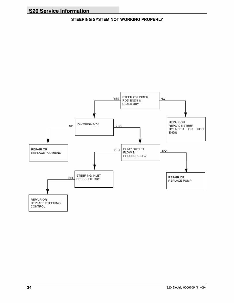
STEERING SYSTEM NOT WORKING PROPERLY
S20 Service Information
35S20 Electric 9006709 (11--09)
ELECTRICALINFORMATION
BEFORE CONDUCTING TESTS:
* Read and Follow ALL Safety Warnings and Precautions asmentioned at the beginning of this manual
*Hydraulic Oil Must Be At Normal Operating Temperatures afterRunning Machine and Hydraulics a Minimum of 5 Minutes
* Examine Machine For Any Linkage Binding or MechanicalProblems
DURING TESTS:
* Call Technical Services if Diagnostic Time ExceedsOneHourWithUnknown Cause or Course of Action
* Maintain Normal Main Brush Pressure as Listed in Operator’sManual
S20 Service Information
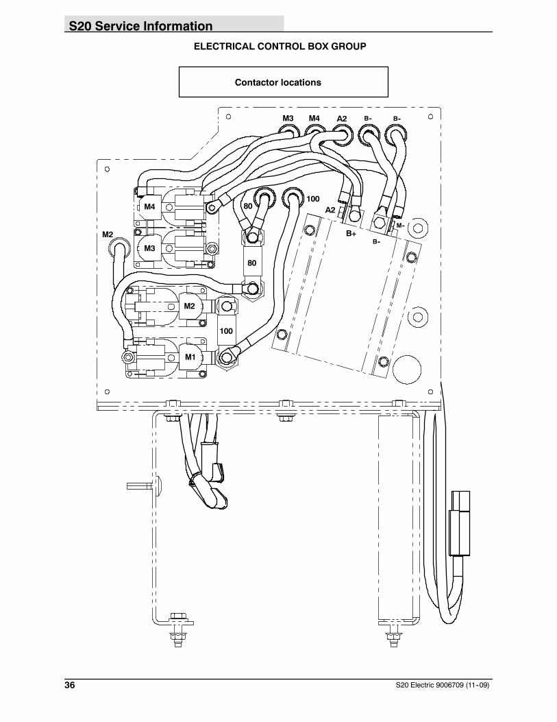
36 S20 Electric 9006709 (11--09)
ELECTRICAL CONTROL BOX GROUP
M3 M4 A2 B-- B--
M3
M4
M1
M2
100
80
80100
B--B+
A2
M--
M2
Contactor locations
S20 Service Information
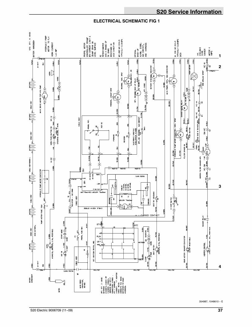
37S20 Electric 9006709 (11--09)
ELECTRICAL SCHEMATIC FIG 1
1
2
4
3
354987, 1048610 -- E
S20 Service Information
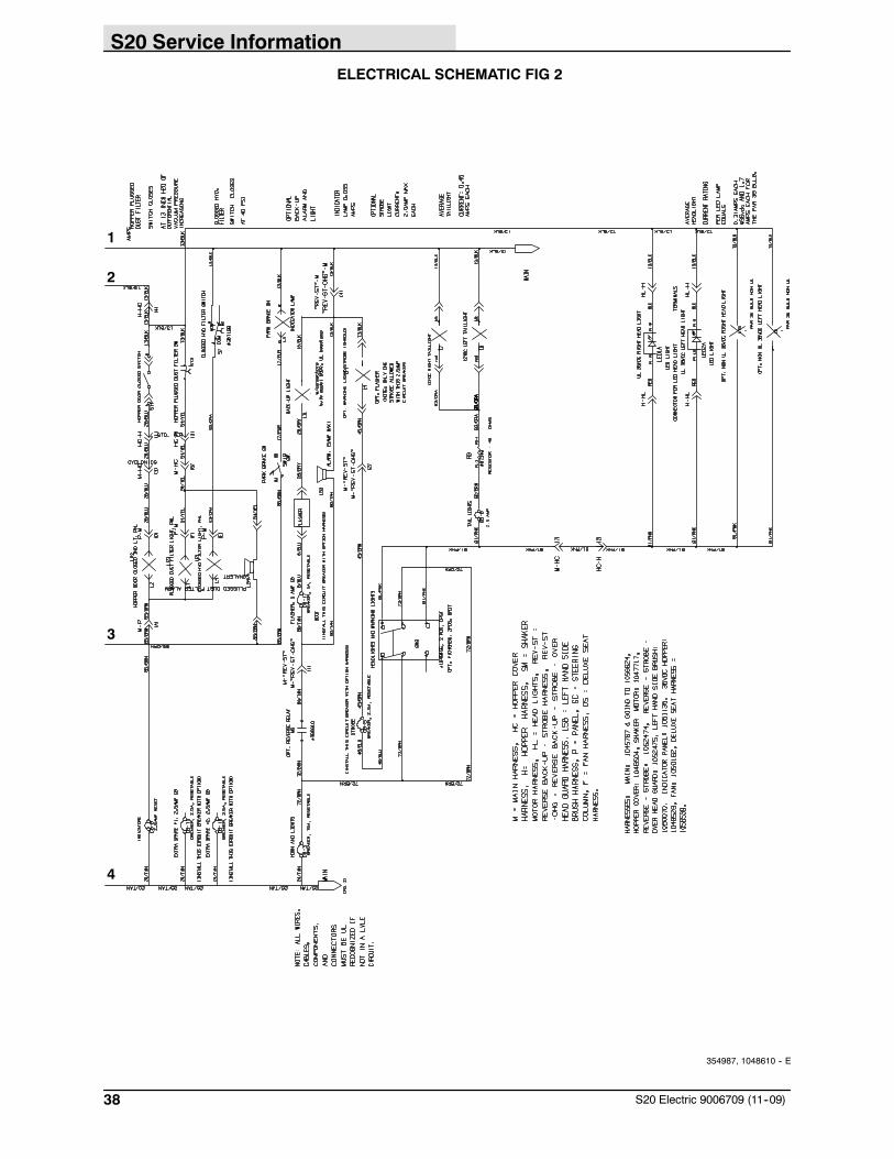
38 S20 Electric 9006709 (11--09)
ELECTRICAL SCHEMATIC FIG 2
1
2
3
4
354987, 1048610 -- E
S20 Service Information
39S20 Electric 9006709 (11--09)
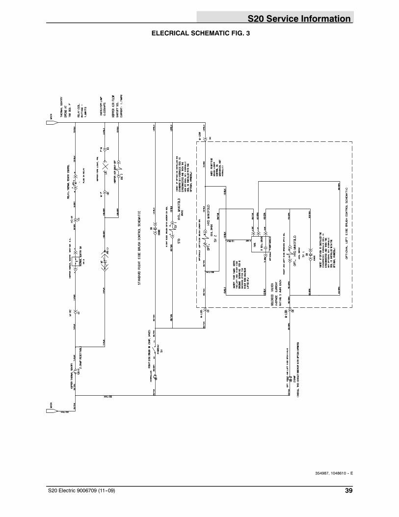
ELECRICAL SCHEMATIC FIG. 3
354987, 1048610 -- E
S20 Service Information
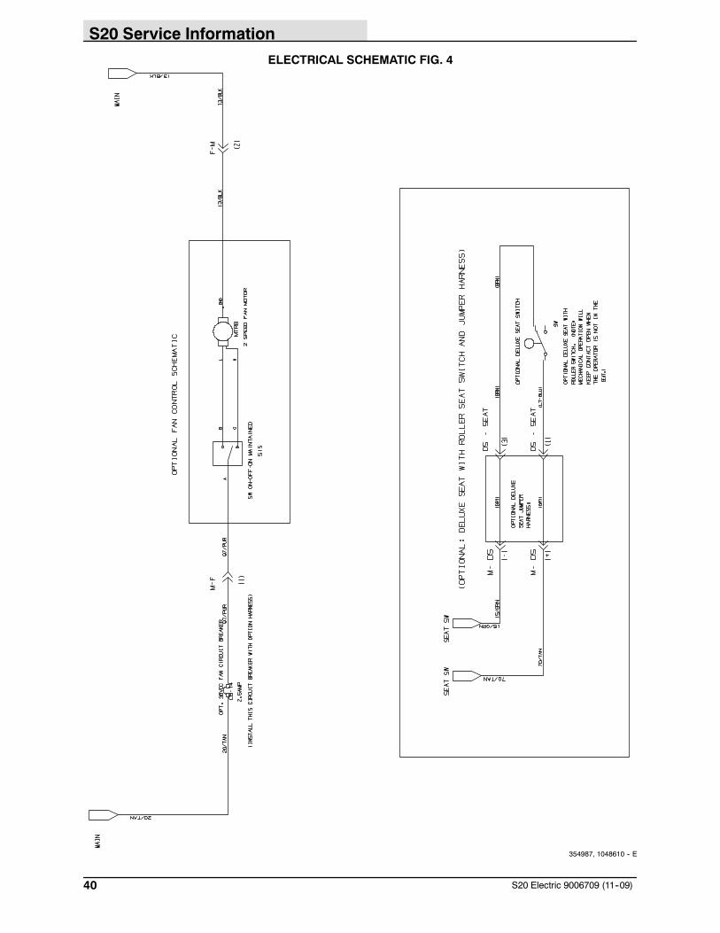
40 S20 Electric 9006709 (11--09)
ELECTRICAL SCHEMATIC FIG. 4
354987, 1048610 -- E