Embed Size (px)
Citation preview
S1C17 Family Application Note
S1C17F00 Series Peripheral Circuit Sample
Software
Rev.1.0
Evaluation board/kit and Development tool important notice
1. This evaluation board/kit or development tool is designed for use for engineering evaluation, demonstration, or development purposes only. Do not use it for other purpose. It is not intended to meet the requirement of design for finished product.
2. This evaluation board/kit or development tool is intended for use by an electronics engineer, and it is not the product for consumer. The user should use this goods properly and safely. Seiko Epson dose not assume any responsibility and liability of any kind of damage and/or fire coursed by usage of it. User should cease to use it when any abnormal issue occurs even during proper and safe use.
3. The part used for this evaluation board/kit or development tool is changed without any notice. NOTICE No part of this material may be reproduced or duplicated in any form or by any means without the written permission of Seiko Epson. Seiko Epson reserves the right to make changes to this material without notice. Seiko Epson does not assume any liability of any kind arising out of any inaccuracies contained in this material or due to its application or use in any product or circuit and, further, there is no representation that this material is applicable to products requiring high level reliability, such as, medical products. Moreover, no license to any intellectual property rights is granted by implication or otherwise, and there is no representation or warranty that anything made in accordance with this material will be free from any patent or copyright infringement of a third party. This material or portions thereof may contain technology or the subject relating to strategic products under the control of the Foreign Exchange and Foreign Trade Law of Japan and may require an export license from the Ministry of Economy, Trade and Industry or other approval from another government agency. All brands or product names mentioned herein are trademarks and/or registered trademarks of their respective companies.
©SEIKO EPSON CORPORATION 2011, All rights reserved.
Table of Contents
1. Overview..................................................................................................................... 1 1.1 Operating Environment ........................................................................................................... 1
2. Explanation of the Sample Software ........................................................................ 2 2.1 Directory Structure and File Structure................................................................................... 2 2.2 Running the Software.............................................................................................................. 3 2.3 Sample Software Menu............................................................................................................ 4 2.4 How to Build Specific Modules............................................................................................... 5
3. Details of Sample Software Functions ..................................................................... 6 3.1 I/O port (P) ................................................................................................................................ 6
3.1.1 Sample software specifications........................................................................................... 6 3.1.2 Hardware conditions ........................................................................................................... 6 3.1.3 Operation overview ............................................................................................................. 7
3.2 Clock Generator (CLG) ............................................................................................................ 8 3.2.1 Sample software specifications........................................................................................... 8 3.2.2 Hardware conditions ........................................................................................................... 8 3.2.3 Overview of operation ......................................................................................................... 8
3.3 8-bit Timer (T8) ......................................................................................................................... 9 3.3.1 Sample software specifications........................................................................................... 9 3.3.2 Hardware conditions ........................................................................................................... 9 3.3.3 Overview of operation ......................................................................................................... 9
3.4 PWM Timer (T16A2) ............................................................................................................... 10 3.4.1 Sample software specifications......................................................................................... 10 3.4.2 Hardware conditions ......................................................................................................... 10 3.4.3 Overview of operation ....................................................................................................... 10
3.5 Clock Timer (CT) .................................................................................................................... 12 3.5.1 Sample software specifications......................................................................................... 12 3.5.2 Hardware conditions ......................................................................................................... 12 3.5.3 Overview of operation ....................................................................................................... 12
3.6 Stopwatch Timer (SWT)......................................................................................................... 13 3.6.1 Sample software specifications......................................................................................... 13 3.6.2 Hardware conditions ......................................................................................................... 13 3.6.3 Overview of operation ....................................................................................................... 13
3.7 Watchdog Timer (WDT) ......................................................................................................... 14 3.7.1 Sample software specifications......................................................................................... 14 3.7.2 Hardware conditions ......................................................................................................... 14 3.7.3 Overview of operation ....................................................................................................... 14
3.8 UART Using OSC3A .............................................................................................................. 15 3.8.1 Sample software specifications......................................................................................... 15 3.8.2 Hardware conditions ......................................................................................................... 15 3.8.3 Overview of operation ....................................................................................................... 15
3.9 UART Using OSC3B .............................................................................................................. 16 3.9.1 Sample software specifications......................................................................................... 16 3.9.2 Hardware conditions ......................................................................................................... 16 3.9.3 Overview of operation ....................................................................................................... 16 3.9.4 OSC3B oscillation frequency calculation........................................................................... 16
3.10 SPI Master .............................................................................................................................. 17
S1C17F00 Series Peripheral Circuit Seiko Epson Corporation i Sample Software (Rev.1.0)
3.10.1 Sample software specifications......................................................................................... 17 3.10.2 Hardware conditions ......................................................................................................... 17 3.10.3 Overview of operation ....................................................................................................... 18
3.11 SPI Slave................................................................................................................................. 19 3.11.1 Sample software specifications......................................................................................... 19 3.11.2 Hardware conditions ......................................................................................................... 19 3.11.3 Overview of operation ....................................................................................................... 19
3.12 I2C Master (I2CM)................................................................................................................... 20 3.12.1 Sample software specifications......................................................................................... 20 3.12.2 Hardware conditions ......................................................................................................... 20 3.12.3 Overview of operation ....................................................................................................... 20
3.13 I2C Slave (I2CS) ..................................................................................................................... 21 3.13.1 Sample software specifications......................................................................................... 21 3.13.2 Hardware conditions ......................................................................................................... 21 3.13.3 Overview of operation ....................................................................................................... 21
3.14 EPD Controller/Driver (EPD) ................................................................................................. 22 3.14.1 Sample software specifications......................................................................................... 22 3.14.2 Hardware conditions ......................................................................................................... 22 3.14.3 Overview of operation ....................................................................................................... 23
3.15 Power Supply Voltage Detection Circuit (SVD) ................................................................... 24 3.15.1 Sample software specifications......................................................................................... 24 3.15.2 Hardware conditions ......................................................................................................... 24 3.15.3 Overview of operation ....................................................................................................... 24
3.16 R/F Converter (RFC) .............................................................................................................. 25 3.16.1 Sample software specifications......................................................................................... 25 3.16.2 Hardware conditions ......................................................................................................... 25 3.16.3 Overview of operation ....................................................................................................... 26
3.17 Real Time Clock (RTC) .......................................................................................................... 27 3.17.1 Sample software specifications......................................................................................... 27 3.17.2 Hardware conditions ......................................................................................................... 27 3.17.3 Overview of operation ....................................................................................................... 27
3.18 Sound Generator (SND)......................................................................................................... 29 3.18.1 Sample software specifications......................................................................................... 29 3.18.2 Hardware conditions ......................................................................................................... 29 3.18.3 Overview of operation ....................................................................................................... 29
3.19 Temperature Detection Circuit (TEM)................................................................................... 30 3.19.1 Sample software specifications......................................................................................... 30 3.19.2 Hardware conditions ......................................................................................................... 30 3.19.3 Overview of operation ....................................................................................................... 30
3.20 Theoretical Regulation (TR) .................................................................................................. 31 3.20.1 Sample software specifications......................................................................................... 31 3.20.2 Hardware conditions ......................................................................................................... 31 3.20.3 Overview of operation ....................................................................................................... 31
3.21 Sleep/Halt Mode Switching ................................................................................................... 32 3.21.1 Sample software specifications......................................................................................... 32 3.21.2 Hardware conditions ......................................................................................................... 32 3.21.3 Overview of operation ....................................................................................................... 32
4. List of Sample Driver Functions ............................................................................. 33 4.1 I/O port (P) .............................................................................................................................. 33 4.2 Clock Generator (CLG_OSC) ................................................................................................ 34 4.3 8-Bit Timer (T8)....................................................................................................................... 35 4.4 PWM Timer (T16A2) ............................................................................................................... 36
ii Seiko Epson Corporation S1C17F00 Series Peripheral Circuit Sample Software (Rev.1.0)
4.5 Clock Timer (CT) .................................................................................................................... 36 4.6 Stopwatch Timer (SWT)......................................................................................................... 37 4.7 Watchdog Timer (WDT) ......................................................................................................... 37 4.8 UART....................................................................................................................................... 38 4.9 SPI........................................................................................................................................... 38 4.10 I2C Master (I2CM)................................................................................................................... 39 4.11 I2C Slave (I2CS) ..................................................................................................................... 40 4.12 EPD Controller/Driver (EPD) ................................................................................................. 41 4.13 Power Supply Voltage Detection Circuit (SVD) ................................................................... 43 4.14 R/F Converter (RFC) .............................................................................................................. 44 4.15 Real Time Clock (RTC) .......................................................................................................... 45 4.16 Sound Generator (SND)......................................................................................................... 45 4.17 Temperature Detection Circuit (TEM)................................................................................... 46 4.18 Theoretical Regulation (TR) .................................................................................................. 46 4.19 MISC........................................................................................................................................ 47 4.20 Multiplexer (MUX) .................................................................................................................. 47 4.21 Power Supply Control Circuit (VD1)..................................................................................... 48
Appendix A Multiplier/Divider ..................................................................................... 49 A.1 Multiplication and Division Using Multiplier/Divider........................................................... 49 A.2 Sum-of-Products Calculation Using Multiplier/Divider....................................................... 49
Revision History ............................................................................................................. 50
S1C17F00 Series Peripheral Circuit Seiko Epson Corporation iii Sample Software (Rev.1.0)
1. Overview
1. Overview
This manual explains how to use the sample software for the S1C17F00 and the operation of it.
The purpose of the S1C17F00 series sample software is to provide examples of the use of each peripheral circuit built into the S1C17F00 series microcontroller.
The S1C17F00 series sample software is provided on a per model basis for installation convenience, but the basic operations of each function are the same.
Use this manual along with the technical manual and development tool manual (S5U1C17001C Manual and S5U1C17001H User Manual).
1.1 Operating Environment
In order to run the S1C17F00 sample software, prepare the following items.
• A board mounted with the S1C17F00 • S5U1C17001H (hereafter ICD mini) • S5U1C17001C (hereafter GNU17)
Note: This sample software has been confirmed to operate on GNU17v2.0.0.
S1C17F00 Series Peripheral Circuit Seiko Epson Corporation 1 Sample Software (Rev.1.0)
2. Explanation of the Sample Software
2. Explanation of the Sample Software
This chapter describes the file configuration the S1C17F00 series sample software and explains how to run it.
The S1C17F00 series sample software consists of sample software and sample drivers.
2.1 Directory Structure and File Structure
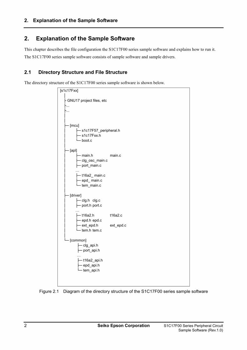
The directory structure of the S1C17F00 series sample software is shown below.
[s1c17Fxx] │ ├ GNU17 project files, etc ├... ├... │ │ ├─ [mcu] │ ├─ s1c17F57_peripheral.h │ ├─ s1c17Fxx.h │ └─ boot.c │ ├─ [apl] │ ├─ main.h main.c │ ├─ clg_osc_main.c │ ├─ port_main.c │ … │ ├─ t16a2_ main.c │ ├─ epd_ main.c │ └─ tem_main.c │ ├─ [driver] │ ├─ clg.h clg.c │ ├─ port.h port.c │ … │ ├─ t16a2.h t16a2.c │ ├─ epd.h epd.c │ ├─ ext_epd.h ext_epd.c │ └─ tem.h tem.c │ └─ [common] ├─ clg_api.h ├─ port_api.h … ├─ t16a2_api.h ├─ epd_api.h └─ tem_api.h
Figure 2.1 Diagram of the directory structure of the S1C17F00 series sample software
2 Seiko Epson Corporation S1C17F00 Series Peripheral Circuit Sample Software (Rev.1.0)
2. Explanation of the Sample Software
(1) s1c17Fxx directory
This directory contains files related to the GNU17 project, and the directories where the source code of the sample software is stored.
(2) mcu directory
It contains files for microcontroller initialization and for defining model-dependent information.
• Header files that define the register addresses etc. of the relevant model (s1c17F57_peripheral.h, etc). • Header file common to all models (s1c17Fxx.h) • Initialization file (boot.c)
(3) apl directory
It contains sample software for the respective peripheral circuits and the header file that defines the definitions used in the sample software.
• Header file for each peripheral circuit (xxx.h) • Sample software for each peripheral circuit (xxx.c)
(4) driver directory
It contains sample drivers for the respective peripheral circuits.
• Header file that defines the register addresses and bit assignments of each peripheral circuit (xxx.h) • Program for each peripheral circuit (xxx.c)
(5) common directory
It contains header files that define the prototypes of functions provided externally by the sample drivers of respective peripheral circuits.
• Header file that defines the constants of arguments and prototypes of functions provided externally by the sample driver of each peripheral circuit (xxx.h)
For software using a sample driver, include the header files residing in the common directory and call the functions of the sample driver.
2.2 Running the Software
Use the following procedure to run the S1C17F00 series sample software.
(1) Import the project
Start up GNU17 and import the S1C17F00 series sample software project.
Refer to "3. Software Development Steps" in the "S5U1C17001C Manual" for how to import a project.
(2) Build the project
Build the S1C17Fxx project with GNU17.
Refer to "5. GNU17 IDE" in the "S5U1C17001C Manual" for how to build a project.
S1C17F00 Series Peripheral Circuit Seiko Epson Corporation 3 Sample Software (Rev.1.0)
2. Explanation of the Sample Software
(3) Connect the ICD mini
Connect the ICD mini to the PC and development board, and switch on the development board.
(4) Load and run the program using the debugger
Start the GNU17 debugger and run the program. The program is loaded in the S1C17F00 and starts.
Refer to "10. Debugger" in the "S5U1C17001C Manual" for more information on how to use the debugger.
2.3 Sample Software Menu
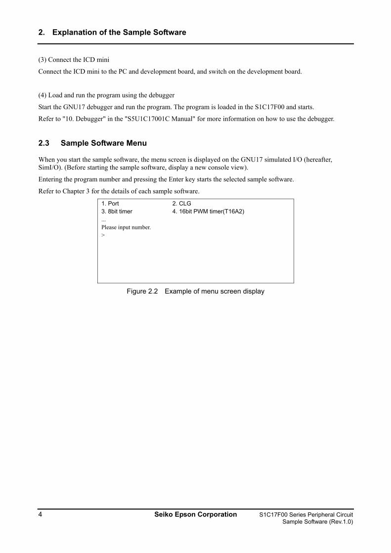
When you start the sample software, the menu screen is displayed on the GNU17 simulated I/O (hereafter, SimI/O). (Before starting the sample software, display a new console view).
Entering the program number and pressing the Enter key starts the selected sample software.
Refer to Chapter 3 for the details of each sample software.
1. Port 2. CLG 3. 8bit timer 4. 16bit PWM timer(T16A2) ... Please input number. >
Figure 2.2 Example of menu screen display
4 Seiko Epson Corporation S1C17F00 Series Peripheral Circuit Sample Software (Rev.1.0)
2. Explanation of the Sample Software
2.4 How to Build Specific Modules
The S1C17Fxx sample software is distributed in a configuration that builds several programs.
You can modify the source code of the sample software so that it builds only the sample software for the peripheral modules required.
The steps are shown below.
(1) Files to be modified
Modify the definition header of each model.
For the S1C17F57 sample software, modify the s1c17F57_peripheral.h file.
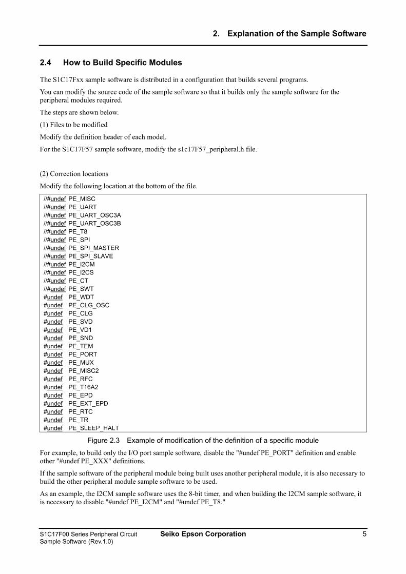
(2) Correction locations
Modify the following location at the bottom of the file.
//#undef PE_MISC //#undef PE_UART //#undef PE_UART_OSC3A //#undef PE_UART_OSC3B //#undef PE_T8 //#undef PE_SPI //#undef PE_SPI_MASTER //#undef PE_SPI_SLAVE //#undef PE_I2CM //#undef PE_I2CS //#undef PE_CT //#undef PE_SWT #undef PE_WDT #undef PE_CLG_OSC #undef PE_CLG #undef PE_SVD #undef PE_VD1 #undef PE_SND #undef PE_TEM #undef PE_PORT #undef PE_MUX #undef PE_MISC2 #undef PE_RFC #undef PE_T16A2 #undef PE_EPD #undef PE_EXT_EPD #undef PE_RTC #undef PE_TR #undef PE_SLEEP_HALT
Figure 2.3 Example of modification of the definition of a specific module
For example, to build only the I/O port sample software, disable the "#undef PE_PORT" definition and enable other "#undef PE_XXX" definitions.
If the sample software of the peripheral module being built uses another peripheral module, it is also necessary to build the other peripheral module sample software to be used.
As an example, the I2CM sample software uses the 8-bit timer, and when building the I2CM sample software, it is necessary to disable "#undef PE_I2CM" and "#undef PE_T8."
S1C17F00 Series Peripheral Circuit Seiko Epson Corporation 5 Sample Software (Rev.1.0)
3. Details of Sample Software Functions
3. Details of Sample Software Functions
This chapter describes the details of the functions of the S1C17F00 series sample software.
3.1 I/O port (P)
3.1.1 Sample software specifications
This sample software performs the following operations using the I/O port.
• Sets the port to input interrupt and detects when the input signal is Low level. • Sets the port to output and outputs a High level or Low level signal.
The port settings used and the port names are as follows.
Table 3.1 I/O port setting list
Setting Port name Input interrupt port P01
P02 P03
Output port P12 P11
Note: The port setting may change depending on the model. Check the source for each model.
3.1.2 Hardware conditions
This sample software operates in conditions in which OSC1 and OSC3A can oscillate.
Refer to the section describing "Clock generator (CLG) oscillation circuit (OSC)" in the respective technical manual for information on how to connect the oscillator.
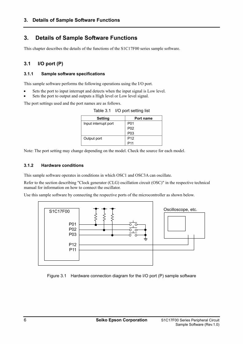
Use this sample software by connecting the respective ports of the microcontroller as shown below.
S1C17F00
P01 P02 P03
P12 P11
Oscilloscope, etc.
Figure 3.1 Hardware connection diagram for the I/O port (P) sample software
6 Seiko Epson Corporation S1C17F00 Series Peripheral Circuit Sample Software (Rev.1.0)
3. Details of Sample Software Functions
3.1.3 Operation overview
(1) Overview of the operation of the sample software
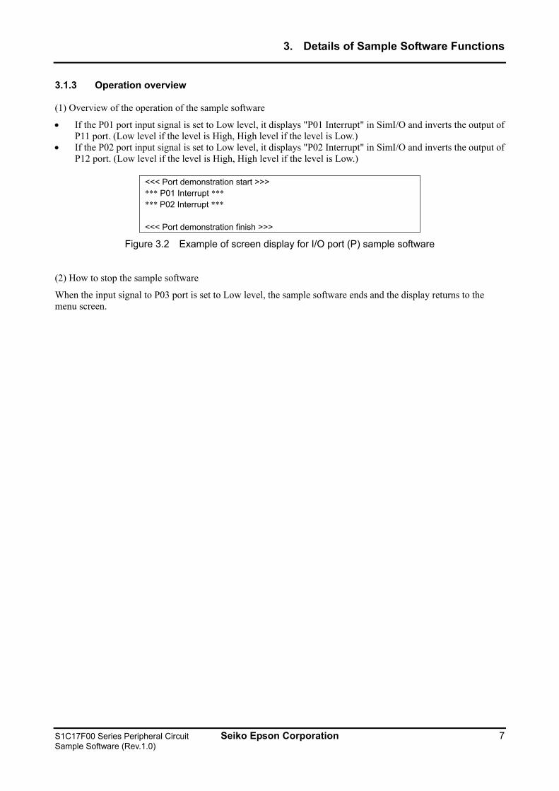
• If the P01 port input signal is set to Low level, it displays "P01 Interrupt" in SimI/O and inverts the output of P11 port. (Low level if the level is High, High level if the level is Low.)
• If the P02 port input signal is set to Low level, it displays "P02 Interrupt" in SimI/O and inverts the output of P12 port. (Low level if the level is High, High level if the level is Low.)
<<< Port demonstration start >>> *** P01 Interrupt *** *** P02 Interrupt *** <<< Port demonstration finish >>>
Figure 3.2 Example of screen display for I/O port (P) sample software
(2) How to stop the sample software
When the input signal to P03 port is set to Low level, the sample software ends and the display returns to the menu screen.
S1C17F00 Series Peripheral Circuit Seiko Epson Corporation 7 Sample Software (Rev.1.0)
3. Details of Sample Software Functions
3.2 Clock Generator (CLG)
3.2.1 Sample software specifications
This sample software performs the following operations using the oscillation circuit.
• Performs OSC3B oscillation and stopping. • Performs OSC1 oscillation and stopping. • Performs OSC3A oscillation and stopping. • Switches system clock from OSC3B to OSC3A. • Switches system clock from OSC3A to OSC1. • Switches system clock from OSC1 to OSC3B.
3.2.2 Hardware conditions
This sample software operates in conditions in which OSC1 and OSC3A can oscillate.
3.2.3 Overview of operation
(1) Overview of the operation of the sample software
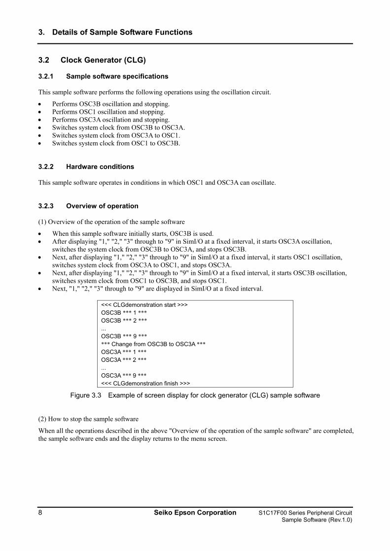
• When this sample software initially starts, OSC3B is used. • After displaying "1," "2," "3" through to "9" in SimI/O at a fixed interval, it starts OSC3A oscillation,
switches the system clock from OSC3B to OSC3A, and stops OSC3B. • Next, after displaying "1," "2," "3" through to "9" in SimI/O at a fixed interval, it starts OSC1 oscillation,
switches system clock from OSC3A to OSC1, and stops OSC3A. • Next, after displaying "1," "2," "3" through to "9" in SimI/O at a fixed interval, it starts OSC3B oscillation,
switches system clock from OSC1 to OSC3B, and stops OSC1. • Next, "1," "2," "3" through to "9" are displayed in SimI/O at a fixed interval.
<<< CLGdemonstration start >>> OSC3B *** 1 *** OSC3B *** 2 *** ... OSC3B *** 9 *** *** Change from OSC3B to OSC3A *** OSC3A *** 1 *** OSC3A *** 2 *** ... OSC3A *** 9 *** <<< CLGdemonstration finish >>>
Figure 3.3 Example of screen display for clock generator (CLG) sample software
(2) How to stop the sample software
When all the operations described in the above "Overview of the operation of the sample software" are completed, the sample software ends and the display returns to the menu screen.
8 Seiko Epson Corporation S1C17F00 Series Peripheral Circuit Sample Software (Rev.1.0)
3. Details of Sample Software Functions
3.3 8-bit Timer (T8)
3.3.1 Sample software specifications
This sample software performs the following operations using the 8-bit timer.
• An 8-bit timer interrupt is generated, and the timer's counter value is acquired. • While waiting for an interrupt, the power consumption is reduced by putting the CPU into halt mode.
3.3.2 Hardware conditions
This sample software operates in conditions in which OSC1 and OSC3A can oscillate.
3.3.3 Overview of operation
(1) Overview of the operation of the sample software
• It starts 8-bit timer interrupt, and puts the CPU into halt mode. • When the 8-bit timer interrupt occurs, it releases the CPU halt mode, saves the counter value of the 8-bit
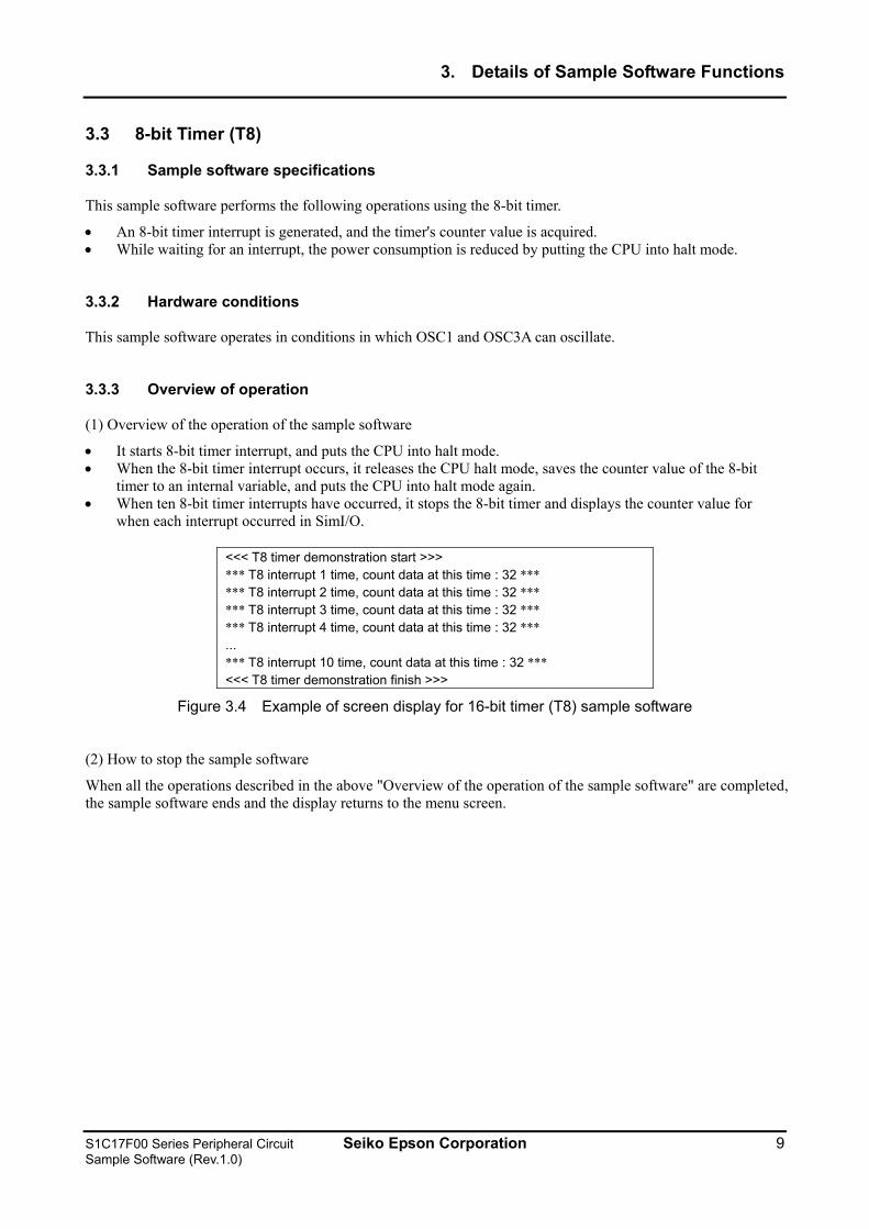
timer to an internal variable, and puts the CPU into halt mode again. • When ten 8-bit timer interrupts have occurred, it stops the 8-bit timer and displays the counter value for
when each interrupt occurred in SimI/O.
<<< T8 timer demonstration start >>> *** T8 interrupt 1 time, count data at this time : 32 *** *** T8 interrupt 2 time, count data at this time : 32 *** *** T8 interrupt 3 time, count data at this time : 32 *** *** T8 interrupt 4 time, count data at this time : 32 *** ... *** T8 interrupt 10 time, count data at this time : 32 *** <<< T8 timer demonstration finish >>>
Figure 3.4 Example of screen display for 16-bit timer (T8) sample software
(2) How to stop the sample software
When all the operations described in the above "Overview of the operation of the sample software" are completed, the sample software ends and the display returns to the menu screen.
S1C17F00 Series Peripheral Circuit Seiko Epson Corporation 9 Sample Software (Rev.1.0)
3. Details of Sample Software Functions
3.4 PWM Timer (T16A2)
3.4.1 Sample software specifications
This sample software performs the following operations using the PWM timer.
• The sample software causes PWM timer compare A match interrupts five times in normal mode and acquires counter values of the timer.
• The sample software causes PWM timer compare B match interrupts five times in normal and half clock modes, and acquires counter values of their timer.
• The sample software outputs the PWM waveform to the TOUTA1 terminal in normal and half clock modes. • While waiting for an interrupt, the power consumption is reduced by putting the CPU into halt mode.
3.4.2 Hardware conditions
This sample software operates in the condition where the crystal oscillator or ceramic oscillator is connected to OSC3A.
Refer to the section describing "Clock generator (CLG)" in the "S1C177xx Series Technical Manual" for information on how to connect the oscillator.
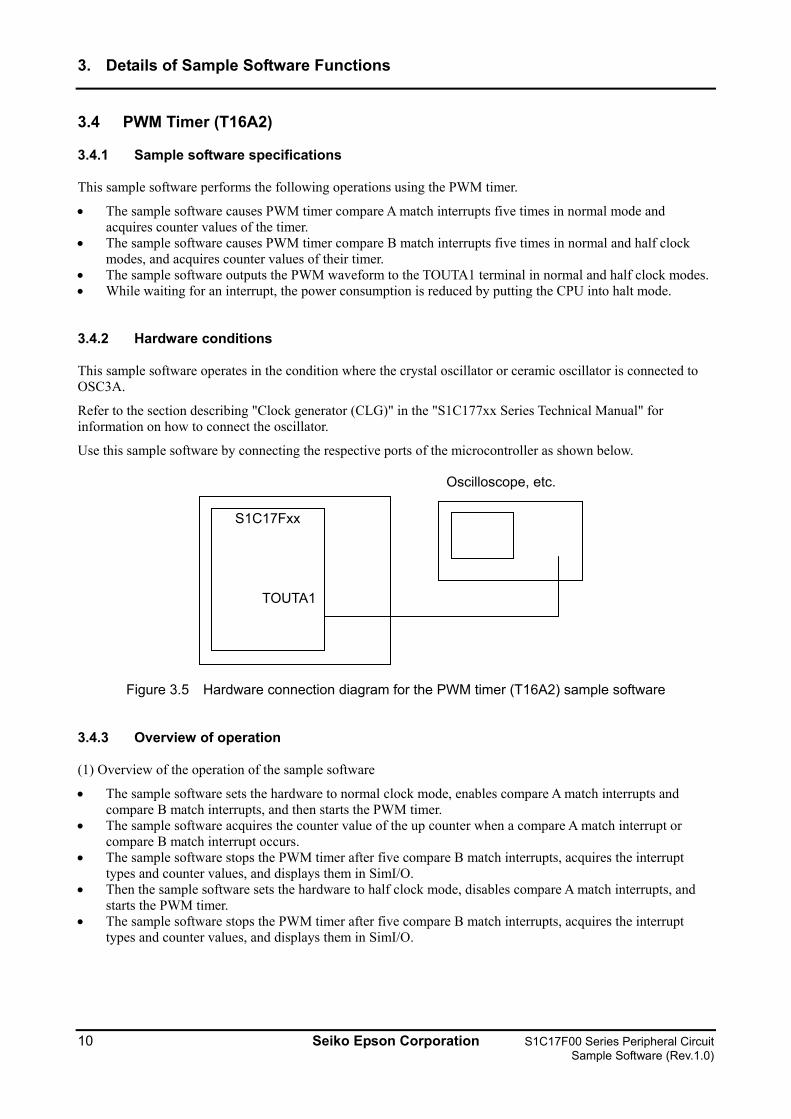
Use this sample software by connecting the respective ports of the microcontroller as shown below.
Oscilloscope, etc. S1C17Fxx
TOUTA1
Figure 3.5 Hardware connection diagram for the PWM timer (T16A2) sample software
3.4.3 Overview of operation
(1) Overview of the operation of the sample software
• The sample software sets the hardware to normal clock mode, enables compare A match interrupts and compare B match interrupts, and then starts the PWM timer.
• The sample software acquires the counter value of the up counter when a compare A match interrupt or compare B match interrupt occurs.
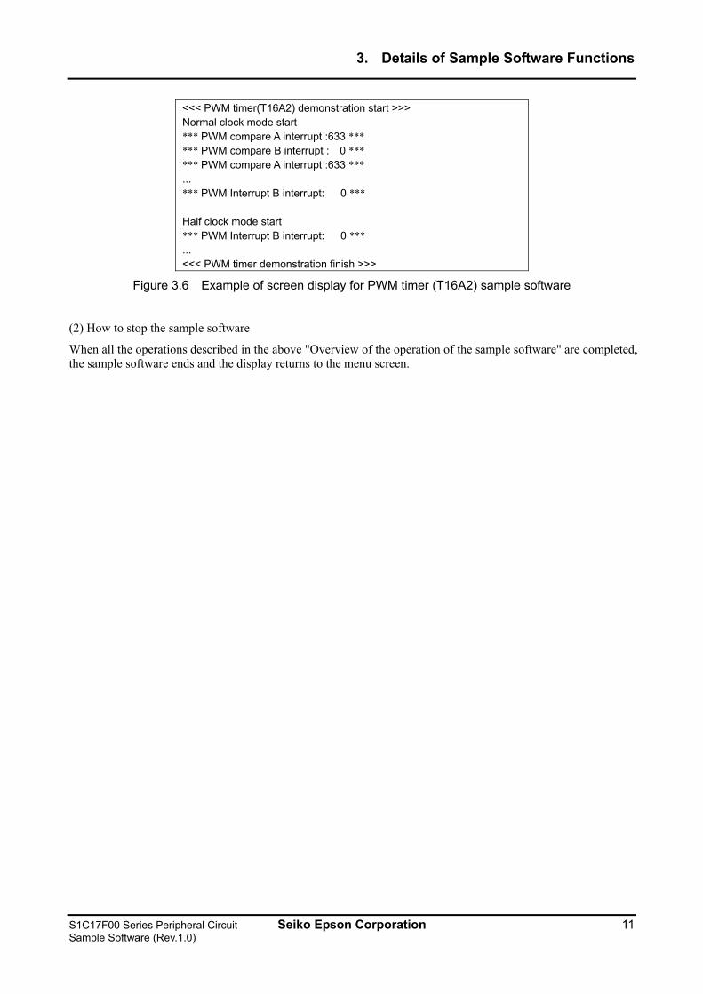
• The sample software stops the PWM timer after five compare B match interrupts, acquires the interrupt types and counter values, and displays them in SimI/O.
• Then the sample software sets the hardware to half clock mode, disables compare A match interrupts, and starts the PWM timer.
• The sample software stops the PWM timer after five compare B match interrupts, acquires the interrupt types and counter values, and displays them in SimI/O.
10 Seiko Epson Corporation S1C17F00 Series Peripheral Circuit Sample Software (Rev.1.0)
3. Details of Sample Software Functions
<<< PWM timer(T16A2) demonstration start >>> Normal clock mode start *** PWM compare A interrupt :633 *** *** PWM compare B interrupt : 0 *** *** PWM compare A interrupt :633 *** ... *** PWM Interrupt B interrupt: 0 *** Half clock mode start *** PWM Interrupt B interrupt: 0 *** ... <<< PWM timer demonstration finish >>>
Figure 3.6 Example of screen display for PWM timer (T16A2) sample software
(2) How to stop the sample software
When all the operations described in the above "Overview of the operation of the sample software" are completed, the sample software ends and the display returns to the menu screen.
S1C17F00 Series Peripheral Circuit Seiko Epson Corporation 11 Sample Software (Rev.1.0)
3. Details of Sample Software Functions
3.5 Clock Timer (CT)
3.5.1 Sample software specifications
This sample software performs the following operations using the clock timer.
• It causes a clock timer interrupt and calculates the elapsed time. • While waiting for an interrupt, the power consumption is reduced by putting the CPU into halt mode.
3.5.2 Hardware conditions
This sample software operates in conditions in which OSC1 and OSC3A can oscillate.
3.5.3 Overview of operation
(1) Overview of the operation of the sample software
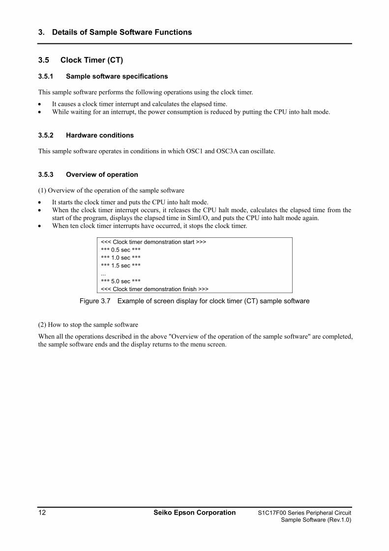
• It starts the clock timer and puts the CPU into halt mode. • When the clock timer interrupt occurs, it releases the CPU halt mode, calculates the elapsed time from the
start of the program, displays the elapsed time in SimI/O, and puts the CPU into halt mode again. • When ten clock timer interrupts have occurred, it stops the clock timer.
<<< Clock timer demonstration start >>> *** 0.5 sec *** *** 1.0 sec *** *** 1.5 sec *** ... *** 5.0 sec *** <<< Clock timer demonstration finish >>>
Figure 3.7 Example of screen display for clock timer (CT) sample software
(2) How to stop the sample software
When all the operations described in the above "Overview of the operation of the sample software" are completed, the sample software ends and the display returns to the menu screen.
12 Seiko Epson Corporation S1C17F00 Series Peripheral Circuit Sample Software (Rev.1.0)
3. Details of Sample Software Functions
3.6 Stopwatch Timer (SWT)
3.6.1 Sample software specifications
This sample software performs the following operations using the stopwatch timer.
• It causes a stopwatch timer interrupt and calculates the elapsed time.
3.6.2 Hardware conditions
This sample software operates in conditions in which OSC1 and OSC3A can oscillate.
3.6.3 Overview of operation
(1) Overview of the operation of the sample software
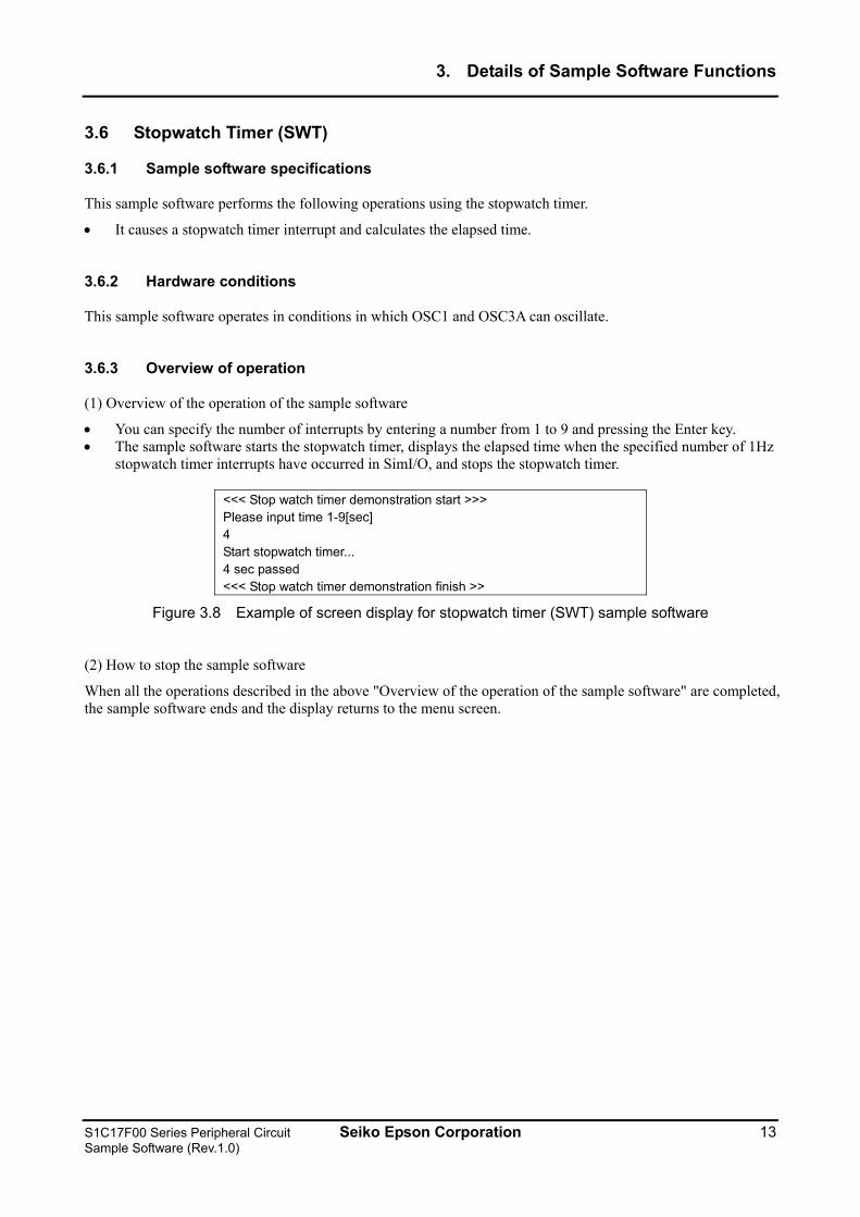
• You can specify the number of interrupts by entering a number from 1 to 9 and pressing the Enter key. • The sample software starts the stopwatch timer, displays the elapsed time when the specified number of 1Hz
stopwatch timer interrupts have occurred in SimI/O, and stops the stopwatch timer.
<<< Stop watch timer demonstration start >>> Please input time 1-9[sec] 4 Start stopwatch timer... 4 sec passed <<< Stop watch timer demonstration finish >>
Figure 3.8 Example of screen display for stopwatch timer (SWT) sample software
(2) How to stop the sample software
When all the operations described in the above "Overview of the operation of the sample software" are completed, the sample software ends and the display returns to the menu screen.
S1C17F00 Series Peripheral Circuit Seiko Epson Corporation 13 Sample Software (Rev.1.0)
3. Details of Sample Software Functions
3.7 Watchdog Timer (WDT)
3.7.1 Sample software specifications
This sample software performs the following operations using the watchdog timer.
• It causes an NMI interrupt with the watchdog timer.
3.7.2 Hardware conditions
This sample software operates in conditions in which OSC1 and OSC3A can oscillate.
3.7.3 Overview of operation
(1) Overview of the operation of the sample software
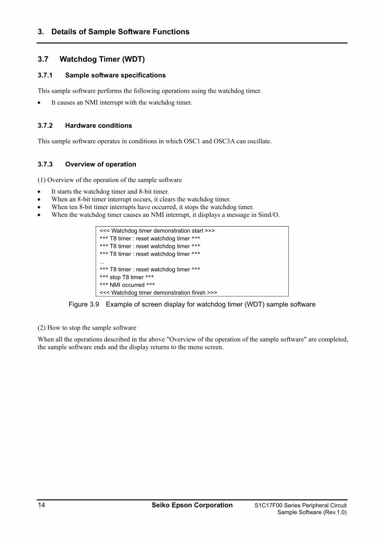
• It starts the watchdog timer and 8-bit timer. • When an 8-bit timer interrupt occurs, it clears the watchdog timer. • When ten 8-bit timer interrupts have occurred, it stops the watchdog timer. • When the watchdog timer causes an NMI interrupt, it displays a message in SimI/O.
<<< Watchdog timer demonstration start >>> *** T8 timer : reset watchdog timer *** *** T8 timer : reset watchdog timer *** *** T8 timer : reset watchdog timer *** ... *** T8 timer : reset watchdog timer *** *** stop T8 timer *** *** NMI occurred *** <<< Watchdog timer demonstration finish >>>
Figure 3.9 Example of screen display for watchdog timer (WDT) sample software
(2) How to stop the sample software
When all the operations described in the above "Overview of the operation of the sample software" are completed, the sample software ends and the display returns to the menu screen.
14 Seiko Epson Corporation S1C17F00 Series Peripheral Circuit Sample Software (Rev.1.0)
3. Details of Sample Software Functions
3.8 UART Using OSC3A
3.8.1 Sample software specifications
This sample software performs the following operations using the UART.
• It uses the UART to send data. • It uses the UART to receive data.
3.8.2 Hardware conditions
This sample software operates in conditions in which OSC1 and OSC3A can oscillate.
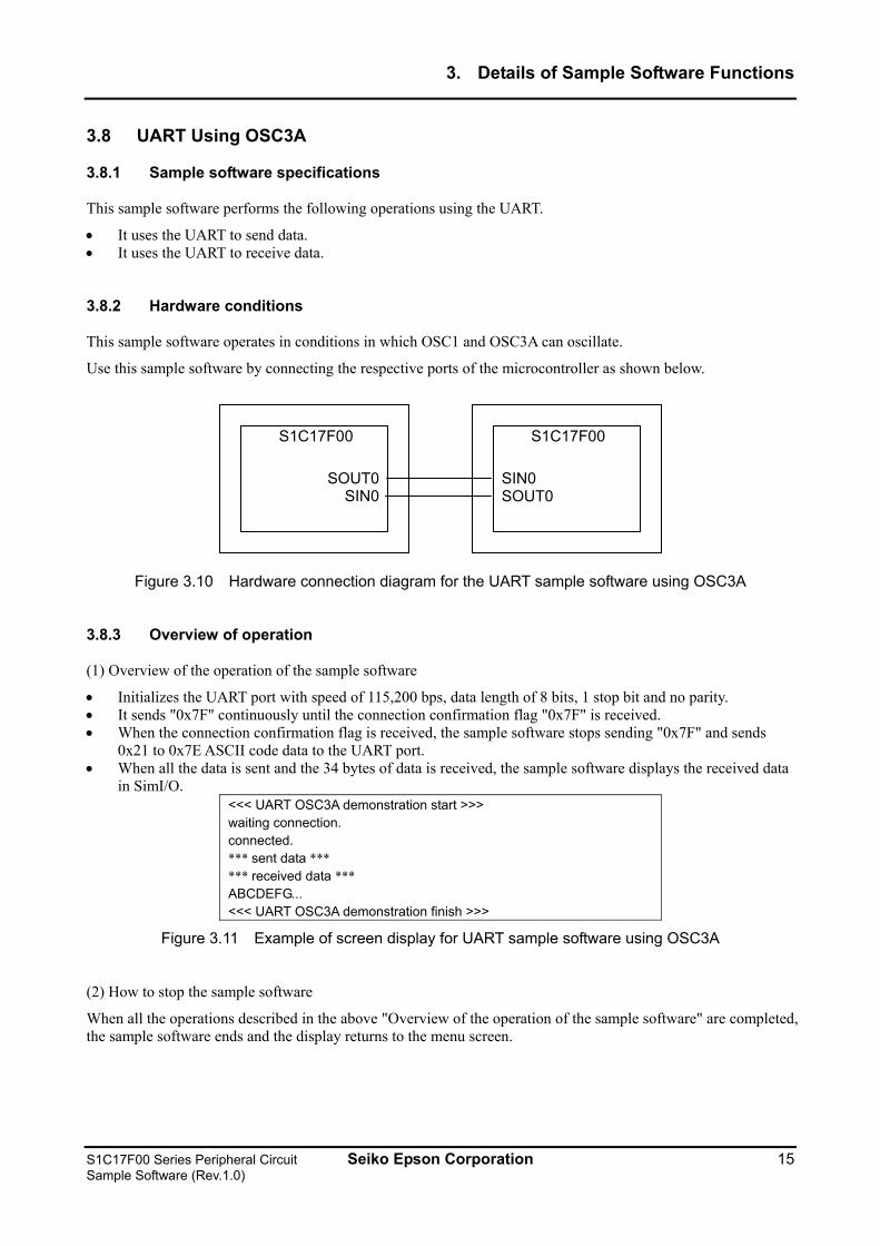
Use this sample software by connecting the respective ports of the microcontroller as shown below.
S1C17F00
SOUT0SIN0
S1C17F00
SIN0 SOUT0
Figure 3.10 Hardware connection diagram for the UART sample software using OSC3A
3.8.3 Overview of operation
(1) Overview of the operation of the sample software
• Initializes the UART port with speed of 115,200 bps, data length of 8 bits, 1 stop bit and no parity. • It sends "0x7F" continuously until the connection confirmation flag "0x7F" is received. • When the connection confirmation flag is received, the sample software stops sending "0x7F" and sends
0x21 to 0x7E ASCII code data to the UART port. • When all the data is sent and the 34 bytes of data is received, the sample software displays the received data
in SimI/O. <<< UART OSC3A demonstration start >>> waiting connection. connected. *** sent data *** *** received data *** ABCDEFG... <<< UART OSC3A demonstration finish >>>
Figure 3.11 Example of screen display for UART sample software using OSC3A
(2) How to stop the sample software
When all the operations described in the above "Overview of the operation of the sample software" are completed, the sample software ends and the display returns to the menu screen.
S1C17F00 Series Peripheral Circuit Seiko Epson Corporation 15 Sample Software (Rev.1.0)
3. Details of Sample Software Functions
3.9 UART Using OSC3B
3.9.1 Sample software specifications
This sample software performs the following operations using the UART.
• Compares the OSC3B clock and OSC1 counter value, and calculates the frequency of OSC3B. • Sets OSC3B as the UART clock. • It uses the UART to send data. • It uses the UART to receive data.
3.9.2 Hardware conditions
The hardware conditions are the same as for the UART sample software using OSC3A.
3.9.3 Overview of operation
(1) Overview of the operation of the sample software
• The sample software runs an 8-bit timer using OSC3B and an advanced timer using OSC1 and calculates the oscillation frequency of OSC3B.
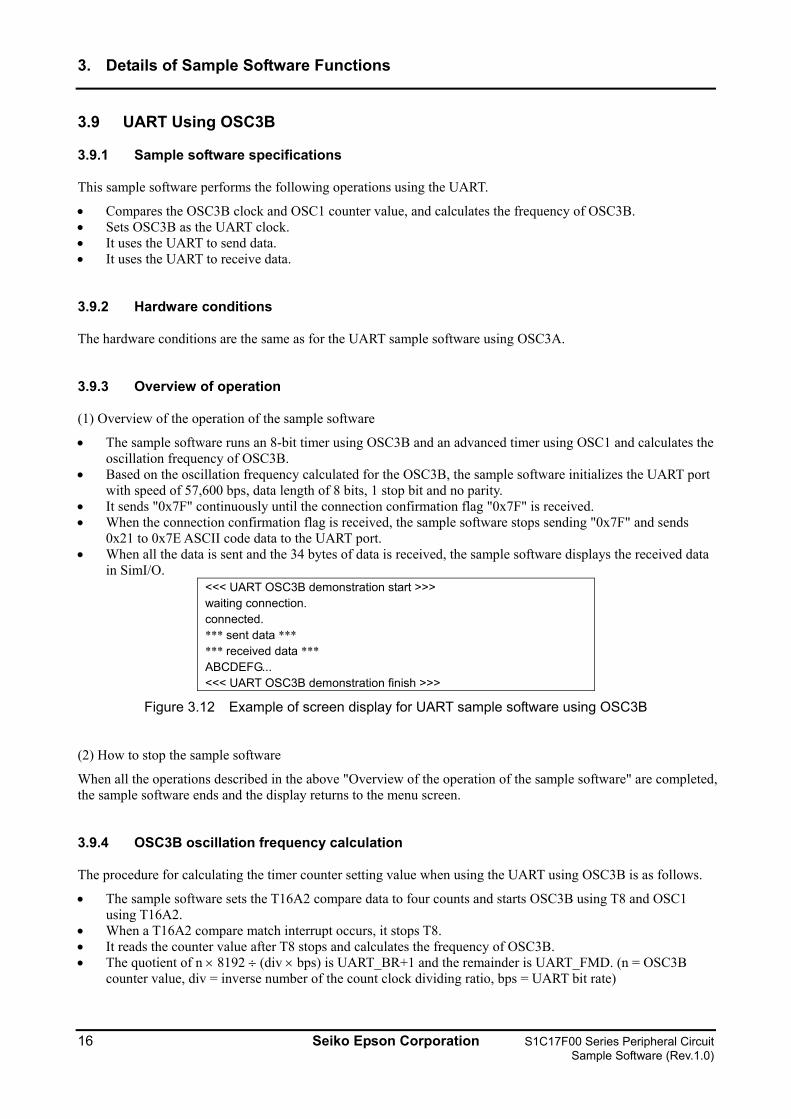
• Based on the oscillation frequency calculated for the OSC3B, the sample software initializes the UART port with speed of 57,600 bps, data length of 8 bits, 1 stop bit and no parity.
• It sends "0x7F" continuously until the connection confirmation flag "0x7F" is received. • When the connection confirmation flag is received, the sample software stops sending "0x7F" and sends
0x21 to 0x7E ASCII code data to the UART port. • When all the data is sent and the 34 bytes of data is received, the sample software displays the received data
in SimI/O. <<< UART OSC3B demonstration start >>> waiting connection. connected. *** sent data *** *** received data *** ABCDEFG... <<< UART OSC3B demonstration finish >>>
Figure 3.12 Example of screen display for UART sample software using OSC3B
(2) How to stop the sample software
When all the operations described in the above "Overview of the operation of the sample software" are completed, the sample software ends and the display returns to the menu screen.
3.9.4 OSC3B oscillation frequency calculation
The procedure for calculating the timer counter setting value when using the UART using OSC3B is as follows.
• The sample software sets the T16A2 compare data to four counts and starts OSC3B using T8 and OSC1 using T16A2.
• When a T16A2 compare match interrupt occurs, it stops T8. • It reads the counter value after T8 stops and calculates the frequency of OSC3B. • The quotient of n × 8192 ÷ (div × bps) is UART_BR+1 and the remainder is UART_FMD. (n = OSC3B
counter value, div = inverse number of the count clock dividing ratio, bps = UART bit rate)
16 Seiko Epson Corporation S1C17F00 Series Peripheral Circuit Sample Software (Rev.1.0)
3. Details of Sample Software Functions
3.10 SPI Master
3.10.1 Sample software specifications
This sample software performs the following operations using the SPI master.
• It sends 8 bytes of data to the SPI slave. • It receives 8 bytes of data from the SPI slave. • While waiting for an interrupt, the power consumption is reduced by putting the CPU into halt mode.
3.10.2 Hardware conditions
This sample software operates in conditions in which OSC1 and OSC3A can oscillate.
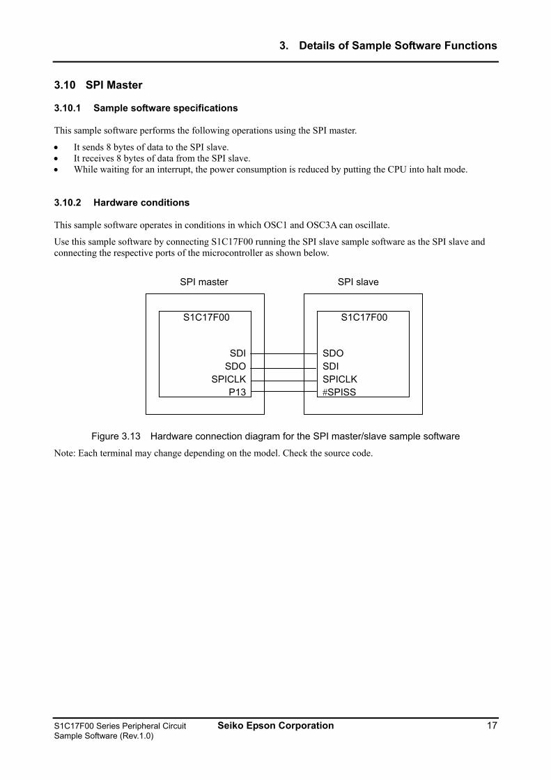
Use this sample software by connecting S1C17F00 running the SPI slave sample software as the SPI slave and connecting the respective ports of the microcontroller as shown below.
S1C17F00
SDISDO
SPICLKP13
S1C17F00
SDO SDI SPICLK #SPISS
SPI master SPI slave
Figure 3.13 Hardware connection diagram for the SPI master/slave sample software
Note: Each terminal may change depending on the model. Check the source code.
S1C17F00 Series Peripheral Circuit Seiko Epson Corporation 17 Sample Software (Rev.1.0)
3. Details of Sample Software Functions
3.10.3 Overview of operation
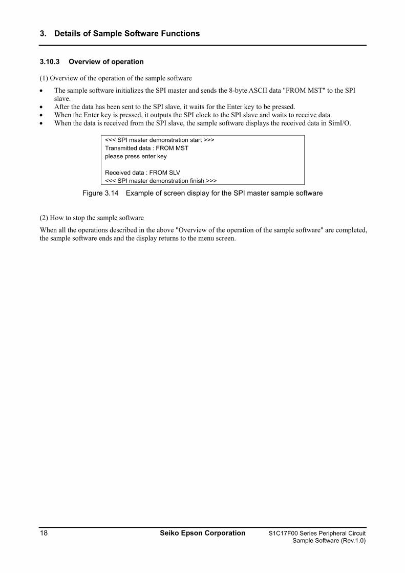
(1) Overview of the operation of the sample software
• The sample software initializes the SPI master and sends the 8-byte ASCII data "FROM MST" to the SPI slave.
• After the data has been sent to the SPI slave, it waits for the Enter key to be pressed. • When the Enter key is pressed, it outputs the SPI clock to the SPI slave and waits to receive data. • When the data is received from the SPI slave, the sample software displays the received data in SimI/O.
<<< SPI master demonstration start >>> Transmitted data : FROM MST please press enter key Received data : FROM SLV <<< SPI master demonstration finish >>>
Figure 3.14 Example of screen display for the SPI master sample software
(2) How to stop the sample software
When all the operations described in the above "Overview of the operation of the sample software" are completed, the sample software ends and the display returns to the menu screen.
18 Seiko Epson Corporation S1C17F00 Series Peripheral Circuit Sample Software (Rev.1.0)
3. Details of Sample Software Functions
3.11 SPI Slave
3.11.1 Sample software specifications
This sample software performs the following operations using the SPI slave.
• It receives 8 bytes of data from the SPI master. • It sends 8 bytes of data to the SPI master. • While waiting for an interrupt, the power consumption is reduced by putting the CPU into halt mode.
3.11.2 Hardware conditions
The hardware conditions are the same as for the sample software using the SPI master.
Use this sample software by connecting S1C17F00 running the SPI master sample software as the SPI slave.
3.11.3 Overview of operation
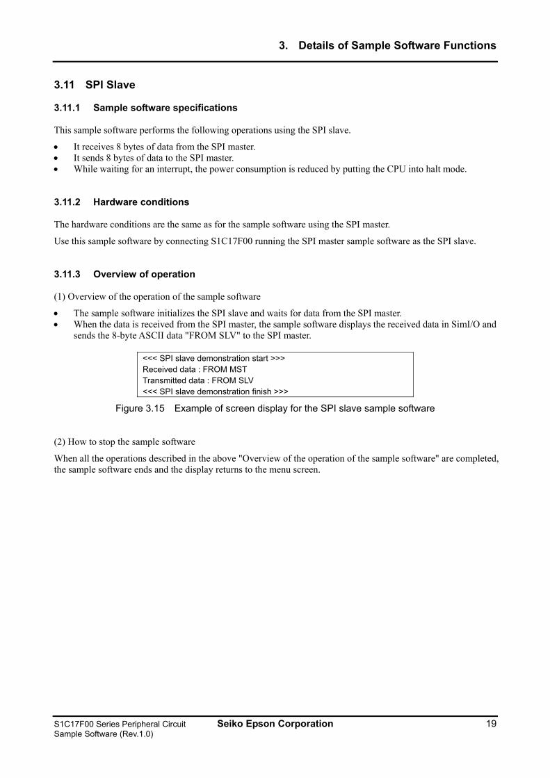
(1) Overview of the operation of the sample software
• The sample software initializes the SPI slave and waits for data from the SPI master. • When the data is received from the SPI master, the sample software displays the received data in SimI/O and
sends the 8-byte ASCII data "FROM SLV" to the SPI master.
<<< SPI slave demonstration start >>> Received data : FROM MST Transmitted data : FROM SLV <<< SPI slave demonstration finish >>>
Figure 3.15 Example of screen display for the SPI slave sample software
(2) How to stop the sample software
When all the operations described in the above "Overview of the operation of the sample software" are completed, the sample software ends and the display returns to the menu screen.
S1C17F00 Series Peripheral Circuit Seiko Epson Corporation 19 Sample Software (Rev.1.0)
3. Details of Sample Software Functions
3.12 I2C Master (I2CM)
3.12.1 Sample software specifications
This sample software performs the following operations using the I2C master.
• It sends data to the I2C slave. • It receives data from the I2C slave.
3.12.2 Hardware conditions
This sample software operates in conditions in which OSC1 and OSC3A can oscillate.
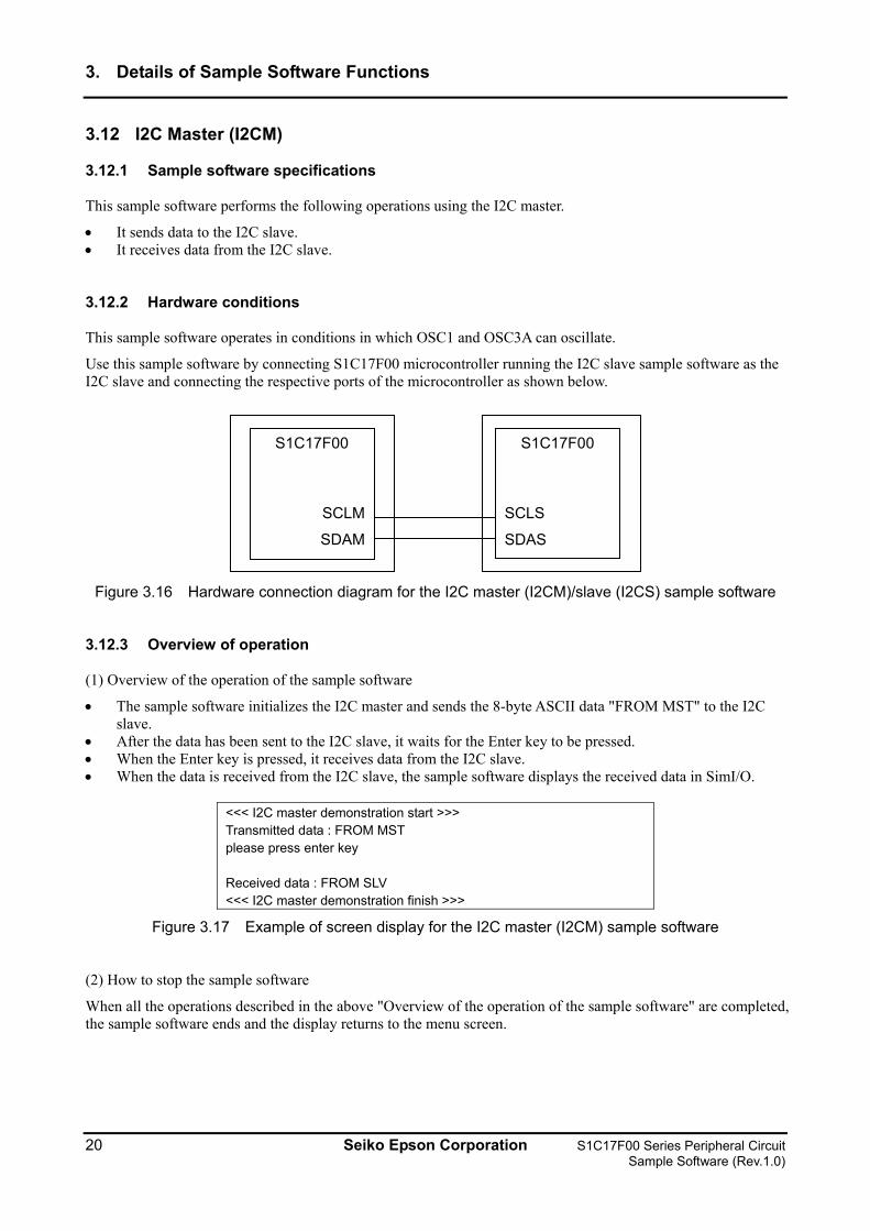
Use this sample software by connecting S1C17F00 microcontroller running the I2C slave sample software as the I2C slave and connecting the respective ports of the microcontroller as shown below.
S1C17F00
SCLM
SDAM
S1C17F00
SCLS
SDAS
Figure 3.16 Hardware connection diagram for the I2C master (I2CM)/slave (I2CS) sample software
3.12.3 Overview of operation
(1) Overview of the operation of the sample software
• The sample software initializes the I2C master and sends the 8-byte ASCII data "FROM MST" to the I2C slave.
• After the data has been sent to the I2C slave, it waits for the Enter key to be pressed. • When the Enter key is pressed, it receives data from the I2C slave. • When the data is received from the I2C slave, the sample software displays the received data in SimI/O.
<<< I2C master demonstration start >>> Transmitted data : FROM MST please press enter key Received data : FROM SLV <<< I2C master demonstration finish >>>
Figure 3.17 Example of screen display for the I2C master (I2CM) sample software
(2) How to stop the sample software
When all the operations described in the above "Overview of the operation of the sample software" are completed, the sample software ends and the display returns to the menu screen.
20 Seiko Epson Corporation S1C17F00 Series Peripheral Circuit Sample Software (Rev.1.0)
3. Details of Sample Software Functions
3.13 I2C Slave (I2CS)
3.13.1 Sample software specifications
This sample software performs the following operations using the I2C slave.
• It receives data from the I2C master. • It sends data to the I2C master.
3.13.2 Hardware conditions
The hardware conditions are the same as for the sample software using the I2C master (I2CM).
Use this sample software by connecting the S1C17F00 microcontroller running the I2C master (I2CM) sample software as the I2C master.
3.13.3 Overview of operation
(1) Overview of the operation of the sample software
• The sample software initializes the I2C slave and waits for data from the I2C master. • When the data is received from the I2C master, the sample software displays the received data in SimI/O
and sends the 8-byte ASCII data "FROM SLV" to the I2C master.
<<< I2C slave demonstration start >>> Received data : FROM MST Transmitted data : FROM SLV <<< I2C slave demonstration finish >>>
Figure 3.18 Example of screen display for the I2C slave (I2CS) sample software
(2) How to stop the sample software
When all the operations described in the above "Overview of the operation of the sample software" are completed, the sample software ends and the display returns to the menu screen.
S1C17F00 Series Peripheral Circuit Seiko Epson Corporation 21 Sample Software (Rev.1.0)
3. Details of Sample Software Functions
3.14 EPD Controller/Driver (EPD)
3.14.1 Sample software specifications
This sample software performs the following operations using the EPD controller/driver.
• It sets the power supply of the EPD controller and driver, and extended EPD controller (S1D14F51). • It sets the operation mode of the EPD controller and driver, and extended EPD controller (S1D14F51). • It sets the drive waveform generated by the EPD controller in the EPD and extended EPD controller. • It sets the display data. • It outputs a waveform from the SEG15 or the SEG47 pin/SEG7 pin (Display: white → black → black →
white).
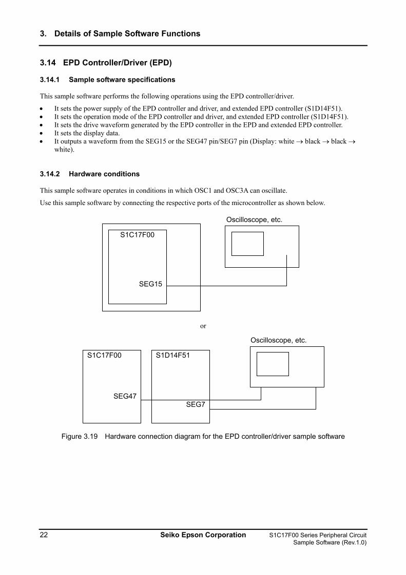
3.14.2 Hardware conditions
This sample software operates in conditions in which OSC1 and OSC3A can oscillate.
Use this sample software by connecting the respective ports of the microcontroller as shown below.
S1C17F00
SEG15
Oscilloscope, etc.
or
S1C17F00
SEG47
S1D14F51
SEG7
Oscilloscope, etc.
Figure 3.19 Hardware connection diagram for the EPD controller/driver sample software
22 Seiko Epson Corporation S1C17F00 Series Peripheral Circuit Sample Software (Rev.1.0)
3. Details of Sample Software Functions
3.14.3 Overview of operation
(1) Overview of the operation of the sample software
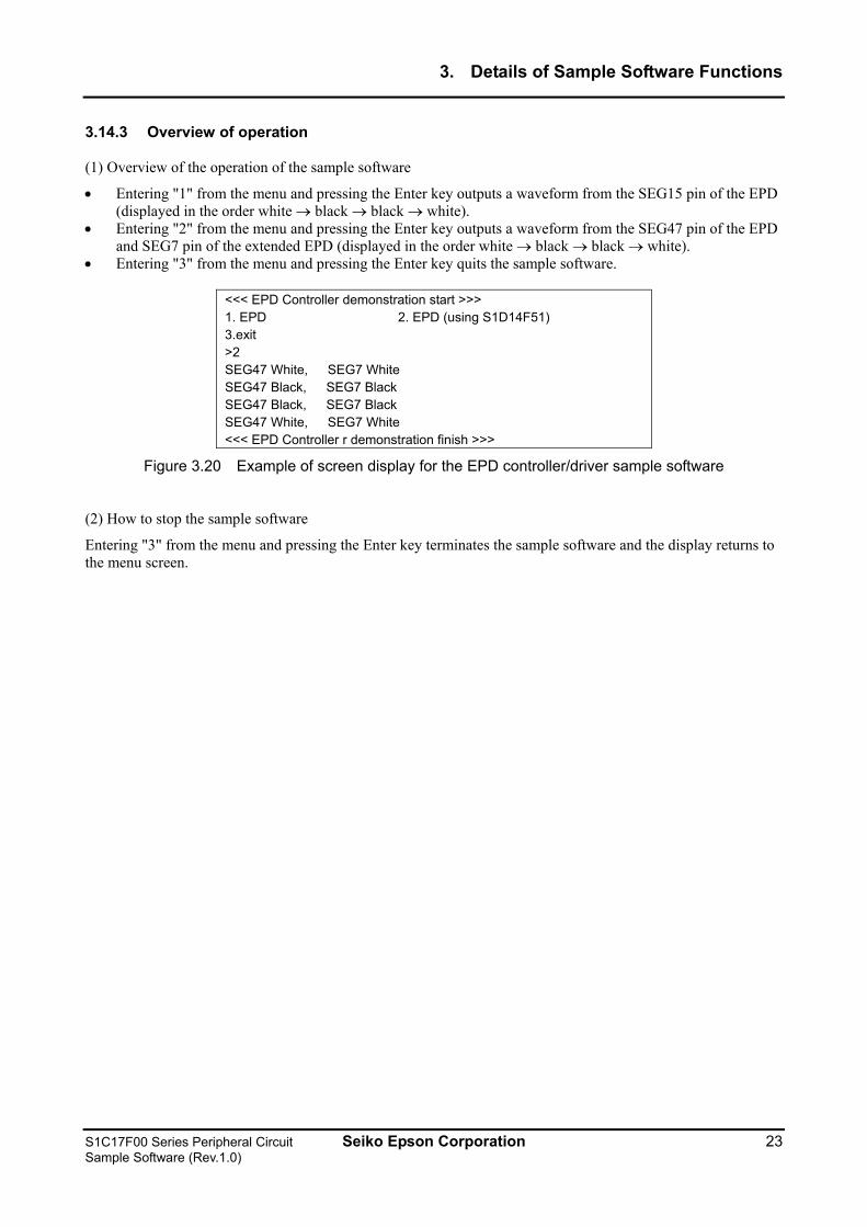
• Entering "1" from the menu and pressing the Enter key outputs a waveform from the SEG15 pin of the EPD (displayed in the order white → black → black → white).
• Entering "2" from the menu and pressing the Enter key outputs a waveform from the SEG47 pin of the EPD and SEG7 pin of the extended EPD (displayed in the order white → black → black → white).
• Entering "3" from the menu and pressing the Enter key quits the sample software.
<<< EPD Controller demonstration start >>> 1. EPD 2. EPD (using S1D14F51) 3.exit >2 SEG47 White, SEG7 White SEG47 Black, SEG7 Black SEG47 Black, SEG7 Black SEG47 White, SEG7 White <<< EPD Controller r demonstration finish >>>
Figure 3.20 Example of screen display for the EPD controller/driver sample software
(2) How to stop the sample software
Entering "3" from the menu and pressing the Enter key terminates the sample software and the display returns to the menu screen.
S1C17F00 Series Peripheral Circuit Seiko Epson Corporation 23 Sample Software (Rev.1.0)
3. Details of Sample Software Functions
3.15 Power Supply Voltage Detection Circuit (SVD)
3.15.1 Sample software specifications
This sample software performs the following operations using the power supply voltage detection circuit (hereafter, SVD circuit).
• The sample software detects the power supply voltage using the SVD circuit.
3.15.2 Hardware conditions
This sample software operates in conditions in which OSC1 and OSC3A can oscillate.
Use this sample software by specifying any power supply voltage.
3.15.3 Overview of operation
(1) Overview of the operation of the sample software
• The sample software detects the power supply voltage (VDD) using the SVD circuit and displays the current VDD voltage on SimI/O. The comparison voltage is in the range from 1.2V to 3.2V.
• The sample software displays "SVD interrupt did not occur" in SimI/O if the power supply voltage is less than 1.2V, or 3.2V or more.
<<< SVD demonstration start >>> Vdd=2.5V <<< SVD demonstration finish >>>
Figure 3.21 Example of screen display for the power supply voltage detection circuit (SVD) sample software
Note: The detected voltage may change depending on the model. Check the source code of each model.
(2) How to stop the sample software
When all the operations described in the above "Overview of the operation of the sample software" are completed, the sample software ends and the display returns to the menu screen.
24 Seiko Epson Corporation S1C17F00 Series Peripheral Circuit Sample Software (Rev.1.0)
3. Details of Sample Software Functions
3.16 R/F Converter (RFC)
3.16.1 Sample software specifications
This sample software performs the following operations using the R/F converter.
• It performs oscillation in the DC oscillation mode for resistance sensor measurement and acquires the counter value.
• It performs oscillation in the AC oscillation mode for resistance sensor measurement and acquires the counter value.
3.16.2 Hardware conditions
This sample software operates in conditions in which OSC1 and OSC3A can oscillate.
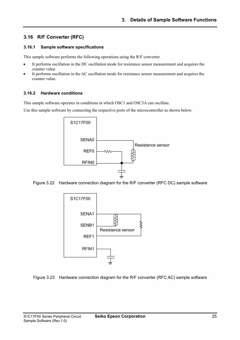
Use this sample software by connecting the respective ports of the microcontroller as shown below.
S1C17F00
SENA0
REF0
RFIN0
Resistance sensor
Figure 3.22 Hardware connection diagram for the R/F converter (RFC DC) sample software
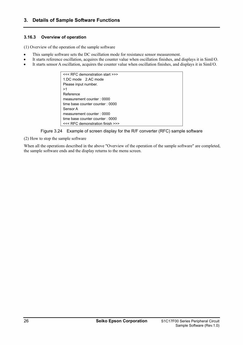
S1C17F00
SENA1
SENB1
REF1
RFIN1
Resistance sensor
Figure 3.23 Hardware connection diagram for the R/F converter (RFC AC) sample software
S1C17F00 Series Peripheral Circuit Seiko Epson Corporation 25 Sample Software (Rev.1.0)
3. Details of Sample Software Functions
3.16.3 Overview of operation
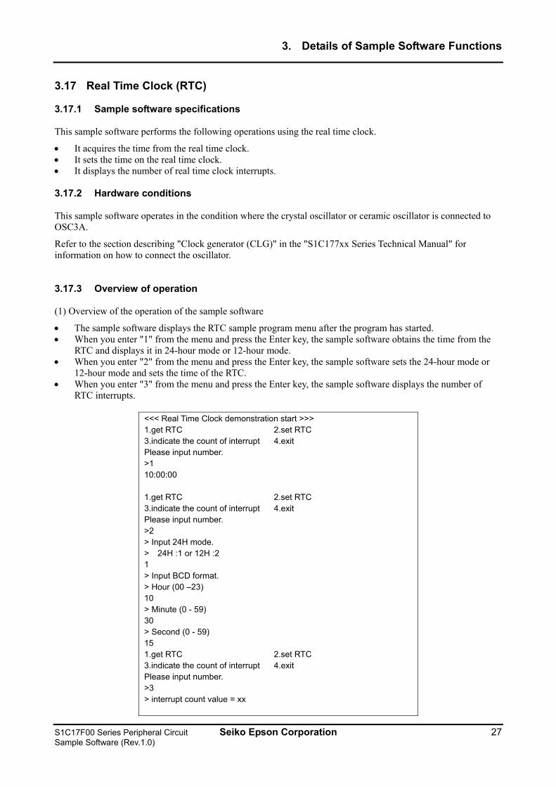
(1) Overview of the operation of the sample software
• This sample software sets the DC oscillation mode for resistance sensor measurement. • It starts reference oscillation, acquires the counter value when oscillation finishes, and displays it in SimI/O. • It starts sensor A oscillation, acquires the counter value when oscillation finishes, and displays it in SimI/O.
<<< RFC demonstration start >>> 1.DC mode 2.AC mode Please input number. >1 Reference measurement counter : 0000 time base counter counter : 0000 Sensor A measurement counter : 0000 time base counter counter : 0000 <<< RFC demonstration finish >>>
Figure 3.24 Example of screen display for the R/F converter (RFC) sample software
(2) How to stop the sample software
When all the operations described in the above "Overview of the operation of the sample software" are completed, the sample software ends and the display returns to the menu screen.
26 Seiko Epson Corporation S1C17F00 Series Peripheral Circuit Sample Software (Rev.1.0)
3. Details of Sample Software Functions
3.17 Real Time Clock (RTC)
3.17.1 Sample software specifications
This sample software performs the following operations using the real time clock.
• It acquires the time from the real time clock. • It sets the time on the real time clock. • It displays the number of real time clock interrupts. 3.17.2 Hardware conditions
This sample software operates in the condition where the crystal oscillator or ceramic oscillator is connected to OSC3A.
Refer to the section describing "Clock generator (CLG)" in the "S1C177xx Series Technical Manual" for information on how to connect the oscillator.
3.17.3 Overview of operation
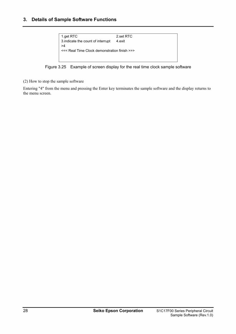
(1) Overview of the operation of the sample software
• The sample software displays the RTC sample program menu after the program has started. • When you enter "1" from the menu and press the Enter key, the sample software obtains the time from the
RTC and displays it in 24-hour mode or 12-hour mode. • When you enter "2" from the menu and press the Enter key, the sample software sets the 24-hour mode or
12-hour mode and sets the time of the RTC. • When you enter "3" from the menu and press the Enter key, the sample software displays the number of
RTC interrupts.
<<< Real Time Clock demonstration start >>> 1.get RTC 2.set RTC 3.indicate the count of interrupt 4.exit Please input number. >1 10:00:00 1.get RTC 2.set RTC 3.indicate the count of interrupt 4.exit Please input number. >2 > Input 24H mode. > 24H :1 or 12H :2 1 > Input BCD format. > Hour (00 –23) 10 > Minute (0 - 59) 30 > Second (0 - 59) 15 1.get RTC 2.set RTC 3.indicate the count of interrupt 4.exit Please input number. >3 > interrupt count value = xx
S1C17F00 Series Peripheral Circuit Seiko Epson Corporation 27 Sample Software (Rev.1.0)
3. Details of Sample Software Functions
1.get RTC 2.set RTC 3.indicate the count of interrupt 4.exit >4 <<< Real Time Clock demonstration finish >>>
Figure 3.25 Example of screen display for the real time clock sample software
(2) How to stop the sample software
Entering "4" from the menu and pressing the Enter key terminates the sample software and the display returns to the menu screen.
28 Seiko Epson Corporation S1C17F00 Series Peripheral Circuit Sample Software (Rev.1.0)
3. Details of Sample Software Functions
3.18 Sound Generator (SND)
3.18.1 Sample software specifications
This sample software program is for evaluating the following conditions.
• It uses the sound generator and outputs from the BZ terminal while changing the frequency output.
3.18.2 Hardware conditions
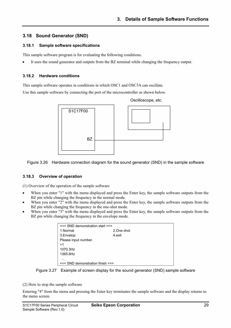
This sample software operates in conditions in which OSC1 and OSC3A can oscillate.
Use this sample software by connecting the port of the microcontroller as shown below.
S1C17F00
BZ
Oscilloscope, etc.
Figure 3.26 Hardware connection diagram for the sound generator (SND) in the sample software
3.18.3 Overview of operation
(1) Overview of the operation of the sample software
• When you enter "1" with the menu displayed and press the Enter key, the sample software outputs from the BZ pin while changing the frequency in the normal mode.
• When you enter "2" with the menu displayed and press the Enter key, the sample software outputs from the BZ pin while changing the frequency in the one-shot mode.
• When you enter "3" with the menu displayed and press the Enter key, the sample software outputs from the BZ pin while changing the frequency in the envelope mode.
<<< SND demonstration start >>> 1.Normal 2.One shot 3.Envelop 4.exit Please input number. >1 1070.3Hz 1365.6Hz ... <<< SND demonstration finish >>>
Figure 3.27 Example of screen display for the sound generator (SND) sample software
(2) How to stop the sample software
Entering "4" from the menu and pressing the Enter key terminates the sample software and the display returns to the menu screen.
S1C17F00 Series Peripheral Circuit Seiko Epson Corporation 29 Sample Software (Rev.1.0)
3. Details of Sample Software Functions
3.19 Temperature Detection Circuit (TEM)
3.19.1 Sample software specifications
This sample software program is for evaluating the following conditions.
• It sets the comparison time for temperature detection. • It measures the temperature and displays the results.
3.19.2 Hardware conditions
This sample software operates in conditions in which OSC1 and OSC3A can oscillate.
3.19.3 Overview of operation
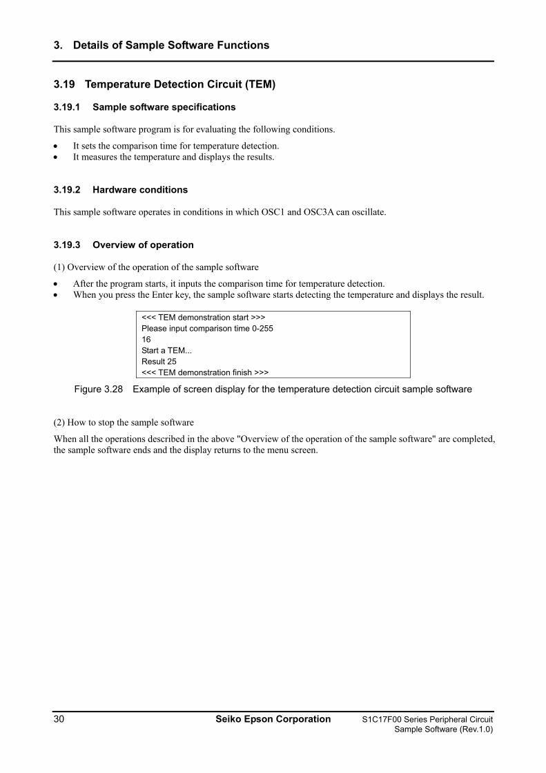
(1) Overview of the operation of the sample software
• After the program starts, it inputs the comparison time for temperature detection. • When you press the Enter key, the sample software starts detecting the temperature and displays the result.
<<< TEM demonstration start >>> Please input comparison time 0-255 16 Start a TEM... Result 25 <<< TEM demonstration finish >>>
Figure 3.28 Example of screen display for the temperature detection circuit sample software
(2) How to stop the sample software
When all the operations described in the above "Overview of the operation of the sample software" are completed, the sample software ends and the display returns to the menu screen.
30 Seiko Epson Corporation S1C17F00 Series Peripheral Circuit Sample Software (Rev.1.0)
3. Details of Sample Software Functions
3.20 Theoretical Regulation (TR)
3.20.1 Sample software specifications
This sample software program is for evaluating the following conditions.
• It sets the adjustment value for theoretical regulation. • It performs theoretical regulation and outputs the results from the REGMON pin.
3.20.2 Hardware conditions
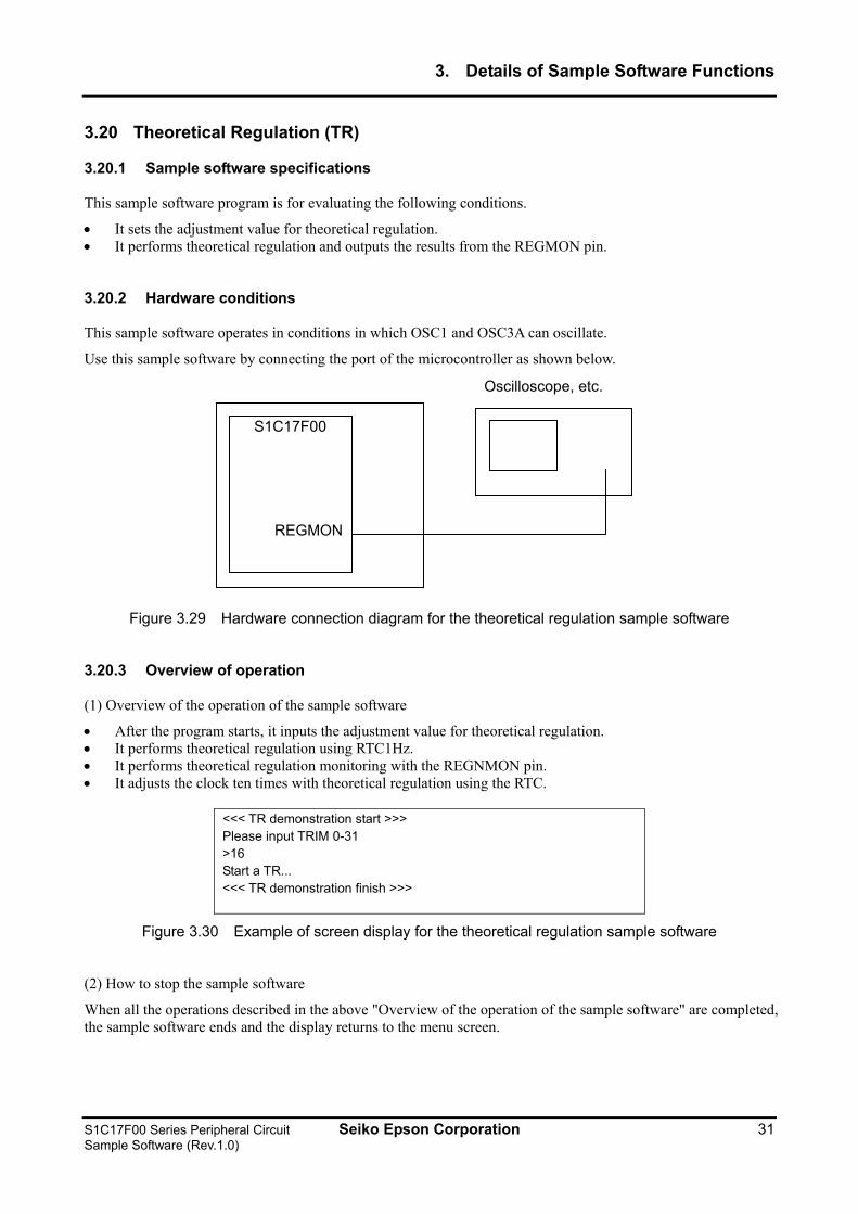
This sample software operates in conditions in which OSC1 and OSC3A can oscillate.
Use this sample software by connecting the port of the microcontroller as shown below.
S1C17F00
REGMON
Oscilloscope, etc.
Figure 3.29 Hardware connection diagram for the theoretical regulation sample software
3.20.3 Overview of operation
(1) Overview of the operation of the sample software
• After the program starts, it inputs the adjustment value for theoretical regulation. • It performs theoretical regulation using RTC1Hz. • It performs theoretical regulation monitoring with the REGNMON pin. • It adjusts the clock ten times with theoretical regulation using the RTC.
<<< TR demonstration start >>> Please input TRIM 0-31 >16 Start a TR... <<< TR demonstration finish >>>
Figure 3.30 Example of screen display for the theoretical regulation sample software
(2) How to stop the sample software
When all the operations described in the above "Overview of the operation of the sample software" are completed, the sample software ends and the display returns to the menu screen.
S1C17F00 Series Peripheral Circuit Seiko Epson Corporation 31 Sample Software (Rev.1.0)
3. Details of Sample Software Functions
3.21 Sleep/Halt Mode Switching
3.21.1 Sample software specifications
This sample software performs the following operations.
• It executes the halt instruction and puts the CPU in the halt mode. • It releases the CPU halt mode using an 8-bit timer interrupt. • It executes the sleep instruction and puts the CPU in the sleep mode. • It releases the CPU sleep mode using a port interrupt.
3.21.2 Hardware conditions
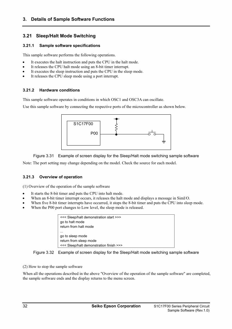
This sample software operates in conditions in which OSC1 and OSC3A can oscillate.
Use this sample software by connecting the respective ports of the microcontroller as shown below.
S1C17F00
P00
Figure 3.31 Example of screen display for the Sleep/Halt mode switching sample software
Note: The port setting may change depending on the model. Check the source for each model.
3.21.3 Overview of operation
(1) Overview of the operation of the sample software
• It starts the 8-bit timer and puts the CPU into halt mode. • When an 8-bit timer interrupt occurs, it releases the halt mode and displays a message in SimI/O. • When five 8-bit timer interrupts have occurred, it stops the 8-bit timer and puts the CPU into sleep mode. • When the P00 port changes to Low level, the sleep mode is released.
<<< Sleep/halt demonstration start >>> go to halt mode return from halt mode ... go to sleep mode return from sleep mode <<< Sleep/halt demonstration finish >>>
Figure 3.32 Example of screen display for the Sleep/Halt mode switching sample software
(2) How to stop the sample software
When all the operations described in the above "Overview of the operation of the sample software" are completed, the sample software ends and the display returns to the menu screen.
32 Seiko Epson Corporation S1C17F00 Series Peripheral Circuit Sample Software (Rev.1.0)
4. List of Sample Driver Functions
4. List of Sample Driver Functions
This chapter lists the sample drivers for each peripheral circuit.
4.1 I/O port (P)
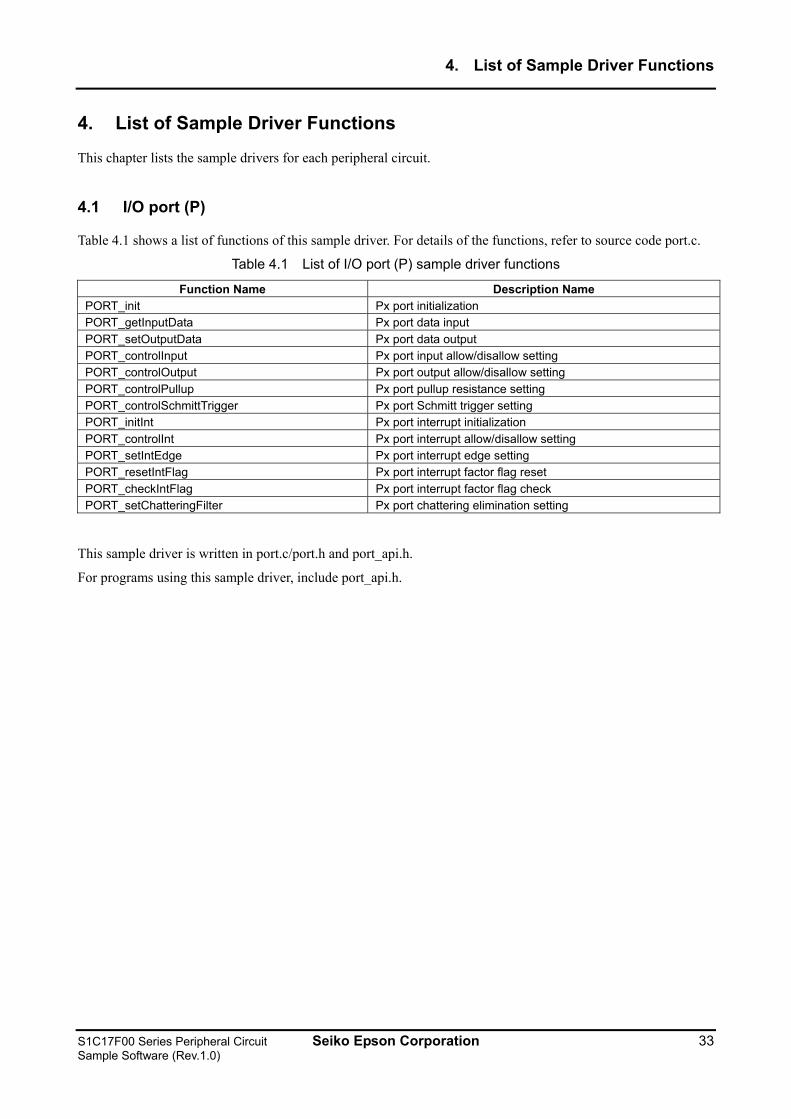
Table 4.1 shows a list of functions of this sample driver. For details of the functions, refer to source code port.c.
Table 4.1 List of I/O port (P) sample driver functions
Function Name Description Name PORT_init Px port initialization PORT_getInputData Px port data input PORT_setOutputData Px port data output PORT_controlInput Px port input allow/disallow setting PORT_controlOutput Px port output allow/disallow setting PORT_controlPullup Px port pullup resistance setting PORT_controlSchmittTrigger Px port Schmitt trigger setting PORT_initInt Px port interrupt initialization PORT_controlInt Px port interrupt allow/disallow setting PORT_setIntEdge Px port interrupt edge setting PORT_resetIntFlag Px port interrupt factor flag reset PORT_checkIntFlag Px port interrupt factor flag check PORT_setChatteringFilter Px port chattering elimination setting
This sample driver is written in port.c/port.h and port_api.h.
For programs using this sample driver, include port_api.h.
S1C17F00 Series Peripheral Circuit Seiko Epson Corporation 33 Sample Software (Rev.1.0)
4. List of Sample Driver Functions
4.2 Clock Generator (CLG_OSC)
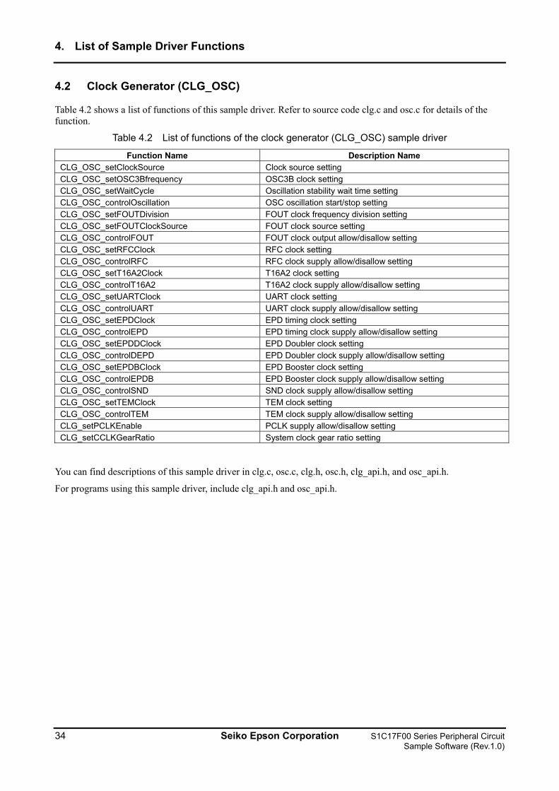
Table 4.2 shows a list of functions of this sample driver. Refer to source code clg.c and osc.c for details of the function.
Table 4.2 List of functions of the clock generator (CLG_OSC) sample driver
Function Name Description Name CLG_OSC_setClockSource Clock source setting CLG_OSC_setOSC3Bfrequency OSC3B clock setting CLG_OSC_setWaitCycle Oscillation stability wait time setting CLG_OSC_controlOscillation OSC oscillation start/stop setting CLG_OSC_setFOUTDivision FOUT clock frequency division setting CLG_OSC_setFOUTClockSource FOUT clock source setting CLG_OSC_controlFOUT FOUT clock output allow/disallow setting CLG_OSC_setRFCClock RFC clock setting CLG_OSC_controlRFC RFC clock supply allow/disallow setting CLG_OSC_setT16A2Clock T16A2 clock setting CLG_OSC_controlT16A2 T16A2 clock supply allow/disallow setting CLG_OSC_setUARTClock UART clock setting CLG_OSC_controlUART UART clock supply allow/disallow setting CLG_OSC_setEPDClock EPD timing clock setting CLG_OSC_controlEPD EPD timing clock supply allow/disallow setting CLG_OSC_setEPDDClock EPD Doubler clock setting CLG_OSC_controlDEPD EPD Doubler clock supply allow/disallow setting CLG_OSC_setEPDBClock EPD Booster clock setting CLG_OSC_controlEPDB EPD Booster clock supply allow/disallow setting CLG_OSC_controlSND SND clock supply allow/disallow setting CLG_OSC_setTEMClock TEM clock setting CLG_OSC_controlTEM TEM clock supply allow/disallow setting CLG_setPCLKEnable PCLK supply allow/disallow setting CLG_setCCLKGearRatio System clock gear ratio setting
You can find descriptions of this sample driver in clg.c, osc.c, clg.h, osc.h, clg_api.h, and osc_api.h.
For programs using this sample driver, include clg_api.h and osc_api.h.
34 Seiko Epson Corporation S1C17F00 Series Peripheral Circuit Sample Software (Rev.1.0)
4. List of Sample Driver Functions
4.3 8-Bit Timer (T8)
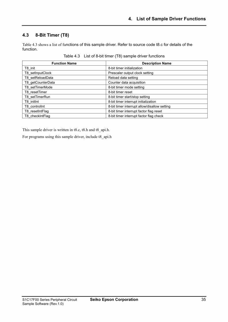
Table 4.3 shows a list of functions of this sample driver. Refer to source code t8.c for details of the function.
Table 4.3 List of 8-bit timer (T8) sample driver functions
Function Name Description Name T8_init 8-bit timer initialization T8_setInputClock Prescaler output clock setting T8_setReloadData Reload data setting T8_getCounterData Counter data acquisition T8_setTimerMode 8-bit timer mode setting T8_resetTimer 8-bit timer reset T8_setTimerRun 8-bit timer start/stop setting T8_initInt 8-bit timer interrupt initialization T8_controlInt 8-bit timer interrupt allow/disallow setting T8_resetIntFlag 8-bit timer interrupt factor flag reset T8_checkIntFlag 8-bit timer interrupt factor flag check
This sample driver is written in t8.c, t8.h and t8_api.h.
For programs using this sample driver, include t8_api.h
S1C17F00 Series Peripheral Circuit Seiko Epson Corporation 35 Sample Software (Rev.1.0)
4. List of Sample Driver Functions
4.4 PWM Timer (T16A2)
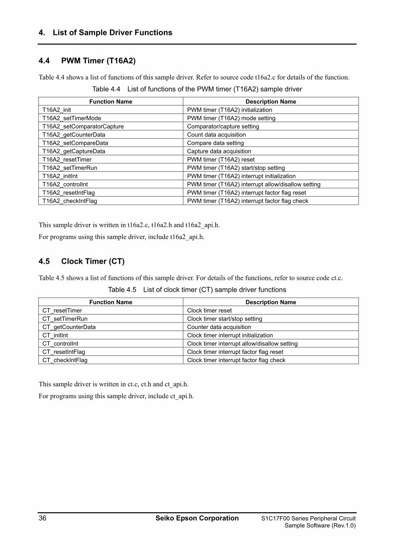
Table 4.4 shows a list of functions of this sample driver. Refer to source code t16a2.c for details of the function.
Table 4.4 List of functions of the PWM timer (T16A2) sample driver
Function Name Description Name T16A2_init PWM timer (T16A2) initialization T16A2_setTimerMode PWM timer (T16A2) mode setting T16A2_setComparatorCapture Comparator/capture setting T16A2_getCounterData Count data acquisition T16A2_setCompareData Compare data setting T16A2_getCaptureData Capture data acquisition T16A2_resetTimer PWM timer (T16A2) reset T16A2_setTimerRun PWM timer (T16A2) start/stop setting T16A2_initInt PWM timer (T16A2) interrupt initialization T16A2_controlInt PWM timer (T16A2) interrupt allow/disallow setting T16A2_resetIntFlag PWM timer (T16A2) interrupt factor flag reset T16A2_checkIntFlag PWM timer (T16A2) interrupt factor flag check
This sample driver is written in t16a2.c, t16a2.h and t16a2_api.h.
For programs using this sample driver, include t16a2_api.h.
4.5 Clock Timer (CT)
Table 4.5 shows a list of functions of this sample driver. For details of the functions, refer to source code ct.c.
Table 4.5 List of clock timer (CT) sample driver functions
Function Name Description Name CT_resetTimer Clock timer reset CT_setTimerRun Clock timer start/stop setting CT_getCounterData Counter data acquisition CT_initInt Clock timer interrupt initialization CT_controlInt Clock timer interrupt allow/disallow setting CT_resetIntFlag Clock timer interrupt factor flag reset CT_checkIntFlag Clock timer interrupt factor flag check
This sample driver is written in ct.c, ct.h and ct_api.h.
For programs using this sample driver, include ct_api.h.
36 Seiko Epson Corporation S1C17F00 Series Peripheral Circuit Sample Software (Rev.1.0)
4. List of Sample Driver Functions
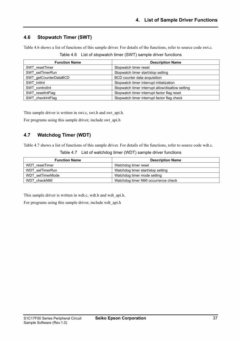
4.6 Stopwatch Timer (SWT)
Table 4.6 shows a list of functions of this sample driver. For details of the functions, refer to source code swt.c.
Table 4.6 List of stopwatch timer (SWT) sample driver functions
Function Name Description Name SWT_resetTimer Stopwatch timer reset SWT_setTimerRun Stopwatch timer start/stop setting SWT_getCounterDataBCD BCD counter data acquisition SWT_initInt Stopwatch timer interrupt initialization SWT_controlInt Stopwatch timer interrupt allow/disallow setting SWT_resetIntFlag Stopwatch timer interrupt factor flag reset SWT_checkIntFlag Stopwatch timer interrupt factor flag check
This sample driver is written in swt.c, swt.h and swt_api.h.
For programs using this sample driver, include swt_api.h
4.7 Watchdog Timer (WDT)
Table 4.7 shows a list of functions of this sample driver. For details of the functions, refer to source code wdt.c.
Table 4.7 List of watchdog timer (WDT) sample driver functions
Function Name Description Name WDT_resetTimer Watchdog timer reset WDT_setTimerRun Watchdog timer start/stop setting WDT_setTimerMode Watchdog timer mode setting WDT_checkNMI Watchdog timer NMI occurrence check
This sample driver is written in wdt.c, wdt.h and wdt_api.h.
For programs using this sample driver, include wdt_api.h
S1C17F00 Series Peripheral Circuit Seiko Epson Corporation 37 Sample Software (Rev.1.0)
4. List of Sample Driver Functions
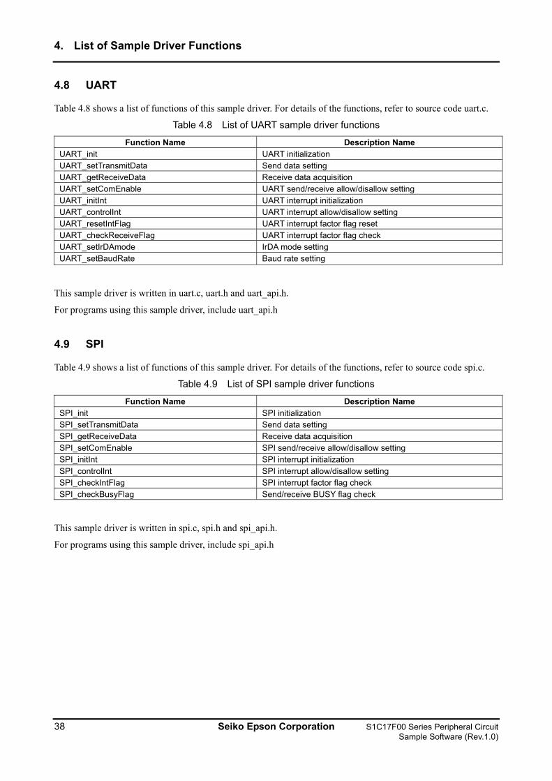
4.8 UART
Table 4.8 shows a list of functions of this sample driver. For details of the functions, refer to source code uart.c.
Table 4.8 List of UART sample driver functions
Function Name Description Name UART_init UART initialization UART_setTransmitData Send data setting UART_getReceiveData Receive data acquisition UART_setComEnable UART send/receive allow/disallow setting UART_initInt UART interrupt initialization UART_controlInt UART interrupt allow/disallow setting UART_resetIntFlag UART interrupt factor flag reset UART_checkReceiveFlag UART interrupt factor flag check UART_setIrDAmode IrDA mode setting UART_setBaudRate Baud rate setting
This sample driver is written in uart.c, uart.h and uart_api.h.
For programs using this sample driver, include uart_api.h
4.9 SPI
Table 4.9 shows a list of functions of this sample driver. For details of the functions, refer to source code spi.c.
Table 4.9 List of SPI sample driver functions
Function Name Description Name SPI_init SPI initialization SPI_setTransmitData Send data setting SPI_getReceiveData Receive data acquisition SPI_setComEnable SPI send/receive allow/disallow setting SPI_initInt SPI interrupt initialization SPI_controlInt SPI interrupt allow/disallow setting SPI_checkIntFlag SPI interrupt factor flag check SPI_checkBusyFlag Send/receive BUSY flag check
This sample driver is written in spi.c, spi.h and spi_api.h.
For programs using this sample driver, include spi_api.h
38 Seiko Epson Corporation S1C17F00 Series Peripheral Circuit Sample Software (Rev.1.0)
4. List of Sample Driver Functions
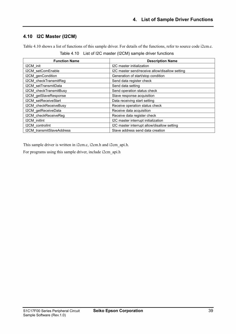
4.10 I2C Master (I2CM)
Table 4.10 shows a list of functions of this sample driver. For details of the functions, refer to source code i2cm.c.
Table 4.10 List of I2C master (I2CM) sample driver functions
Function Name Description Name I2CM_init I2C master initialization I2CM_setComEnable I2C master send/receive allow/disallow setting I2CM_genCondition Generation of start/stop condition I2CM_checkTransmitReg Send data register check I2CM_setTransmitData Send data setting I2CM_checkTransmitBusy Send operation status check I2CM_getSlaveResponse Slave response acquisition I2CM_setReceiveStart Data receiving start setting I2CM_checkReceiveBusy Receive operation status check I2CM_getReceiveData Receive data acquisition I2CM_checkReceiveReg Receive data register check I2CM_initInt I2C master interrupt initialization I2CM_controlInt I2C master interrupt allow/disallow setting I2CM_transmitSlaveAddress Slave address send data creation
This sample driver is written in i2cm.c, i2cm.h and i2cm_api.h.
For programs using this sample driver, include i2cm_api.h
S1C17F00 Series Peripheral Circuit Seiko Epson Corporation 39 Sample Software (Rev.1.0)
4. List of Sample Driver Functions
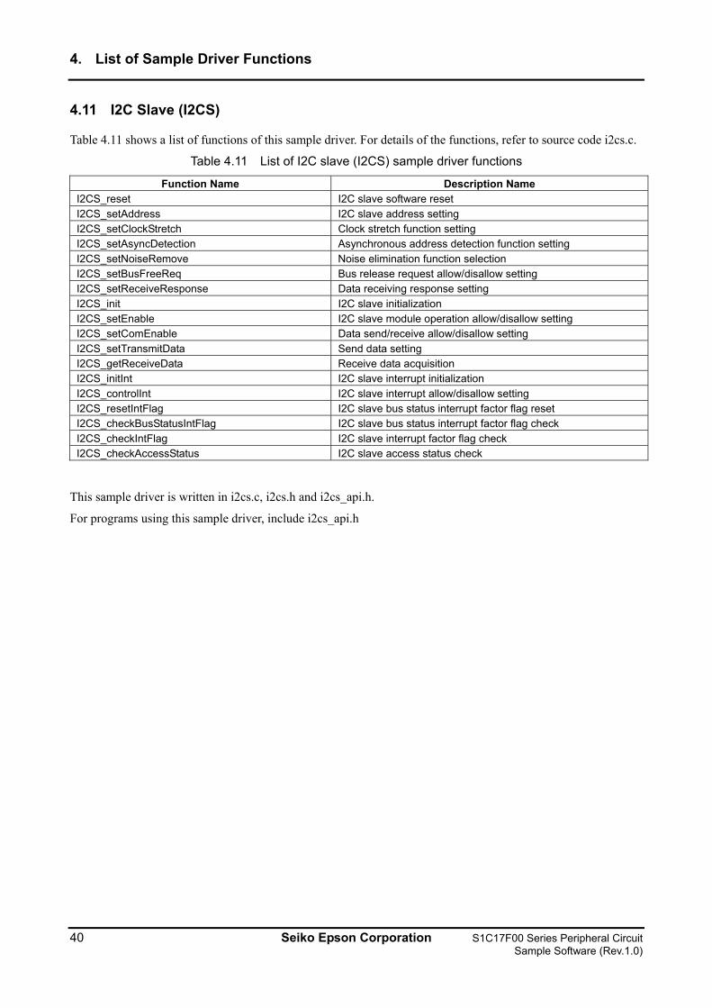
4.11 I2C Slave (I2CS)
Table 4.11 shows a list of functions of this sample driver. For details of the functions, refer to source code i2cs.c.
Table 4.11 List of I2C slave (I2CS) sample driver functions
Function Name Description Name I2CS_reset I2C slave software reset I2CS_setAddress I2C slave address setting I2CS_setClockStretch Clock stretch function setting I2CS_setAsyncDetection Asynchronous address detection function setting I2CS_setNoiseRemove Noise elimination function selection I2CS_setBusFreeReq Bus release request allow/disallow setting I2CS_setReceiveResponse Data receiving response setting I2CS_init I2C slave initialization I2CS_setEnable I2C slave module operation allow/disallow setting I2CS_setComEnable Data send/receive allow/disallow setting I2CS_setTransmitData Send data setting I2CS_getReceiveData Receive data acquisition I2CS_initInt I2C slave interrupt initialization I2CS_controlInt I2C slave interrupt allow/disallow setting I2CS_resetIntFlag I2C slave bus status interrupt factor flag reset I2CS_checkBusStatusIntFlag I2C slave bus status interrupt factor flag check I2CS_checkIntFlag I2C slave interrupt factor flag check I2CS_checkAccessStatus I2C slave access status check
This sample driver is written in i2cs.c, i2cs.h and i2cs_api.h.
For programs using this sample driver, include i2cs_api.h
40 Seiko Epson Corporation S1C17F00 Series Peripheral Circuit Sample Software (Rev.1.0)
4. List of Sample Driver Functions
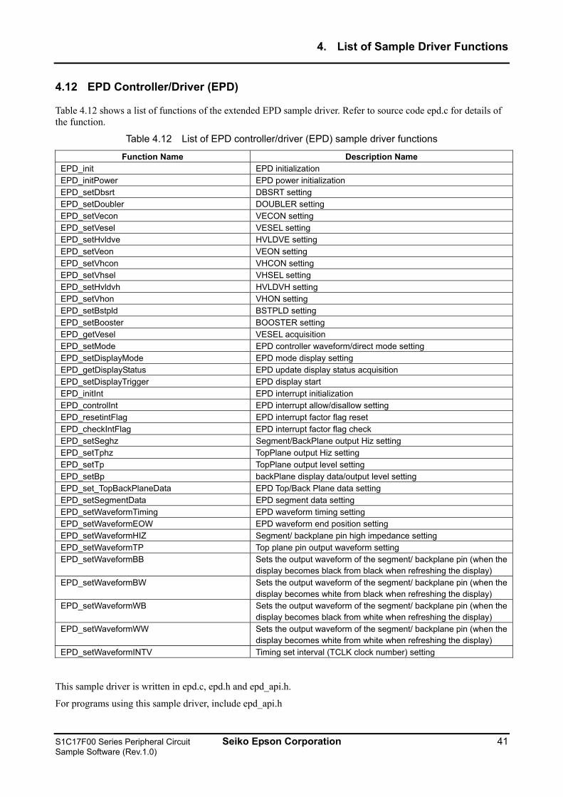
4.12 EPD Controller/Driver (EPD)
Table 4.12 shows a list of functions of the extended EPD sample driver. Refer to source code epd.c for details of the function.
Table 4.12 List of EPD controller/driver (EPD) sample driver functions
Function Name Description Name EPD_init EPD initialization EPD_initPower EPD power initialization EPD_setDbsrt DBSRT setting EPD_setDoubler DOUBLER setting EPD_setVecon VECON setting EPD_setVesel VESEL setting EPD_setHvldve HVLDVE setting EPD_setVeon VEON setting EPD_setVhcon VHCON setting EPD_setVhsel VHSEL setting EPD_setHvldvh HVLDVH setting EPD_setVhon VHON setting EPD_setBstpld BSTPLD setting EPD_setBooster BOOSTER setting EPD_getVesel VESEL acquisition EPD_setMode EPD controller waveform/direct mode setting EPD_setDisplayMode EPD mode display setting EPD_getDisplayStatus EPD update display status acquisition EPD_setDisplayTrigger EPD display start EPD_initInt EPD interrupt initialization EPD_controlInt EPD interrupt allow/disallow setting EPD_resetintFlag EPD interrupt factor flag reset EPD_checkIntFlag EPD interrupt factor flag check EPD_setSeghz Segment/BackPlane output Hiz setting EPD_setTphz TopPlane output Hiz setting EPD_setTp TopPlane output level setting EPD_setBp backPlane display data/output level setting EPD_set_TopBackPlaneData EPD Top/Back Plane data setting EPD_setSegmentData EPD segment data setting EPD_setWaveformTiming EPD waveform timing setting EPD_setWaveformEOW EPD waveform end position setting EPD_setWaveformHIZ Segment/ backplane pin high impedance setting EPD_setWaveformTP Top plane pin output waveform setting EPD_setWaveformBB Sets the output waveform of the segment/ backplane pin (when the
display becomes black from black when refreshing the display) EPD_setWaveformBW Sets the output waveform of the segment/ backplane pin (when the
display becomes white from black when refreshing the display) EPD_setWaveformWB Sets the output waveform of the segment/ backplane pin (when the
display becomes black from white when refreshing the display) EPD_setWaveformWW Sets the output waveform of the segment/ backplane pin (when the
display becomes white from white when refreshing the display) EPD_setWaveformINTV Timing set interval (TCLK clock number) setting
This sample driver is written in epd.c, epd.h and epd_api.h.
For programs using this sample driver, include epd_api.h
S1C17F00 Series Peripheral Circuit Seiko Epson Corporation 41 Sample Software (Rev.1.0)
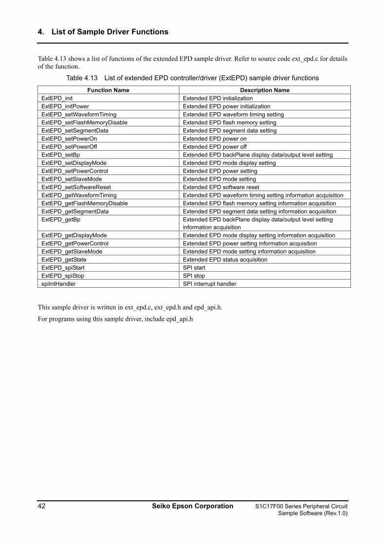
4. List of Sample Driver Functions
Table 4.13 shows a list of functions of the extended EPD sample driver. Refer to source code ext_epd.c for details of the function.
Table 4.13 List of extended EPD controller/driver (ExtEPD) sample driver functions
Function Name Description Name ExtEPD_init Extended EPD initialization ExtEPD_initPower Extended EPD power initialization ExtEPD_setWaveformTiming Extended EPD waveform timing setting ExtEPD_setFlashMemoryDisable Extended EPD flash memory setting ExtEPD_setSegmentData Extended EPD segment data setting ExtEPD_setPowerOn Extended EPD power on ExtEPD_setPowerOff Extended EPD power off ExtEPD_setBp Extended EPD backPlane display data/output level setting ExtEPD_setDisplayMode Extended EPD mode display setting ExtEPD_setPowerControl Extended EPD power setting ExtEPD_setSlaveMode Extended EPD mode setting ExtEPD_setSoftwareReset Extended EPD software reset ExtEPD_getWaveformTiming Extended EPD waveform timing setting information acquisition ExtEPD_getFlashMemoryDisable Extended EPD flash memory setting information acquisition ExtEPD_getSegmentData Extended EPD segment data setting information acquisition ExtEPD_getBp Extended EPD backPlane display data/output level setting
information acquisition ExtEPD_getDisplayMode Extended EPD mode display setting information acquisition ExtEPD_getPowerControl Extended EPD power setting information acquisition ExtEPD_getSlaveMode Extended EPD mode setting information acquisition ExtEPD_getState Extended EPD status acquisition ExtEPD_spiStart SPI start ExtEPD_spiStop SPI stop spiIntHandler SPI interrupt handler
This sample driver is written in ext_epd.c, ext_epd.h and epd_api.h.
For programs using this sample driver, include epd_api.h
42 Seiko Epson Corporation S1C17F00 Series Peripheral Circuit Sample Software (Rev.1.0)
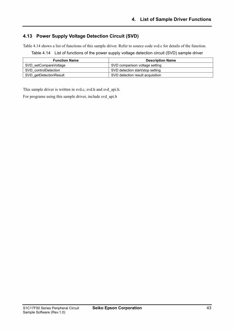
4. List of Sample Driver Functions
4.13 Power Supply Voltage Detection Circuit (SVD)
Table 4.14 shows a list of functions of this sample driver. Refer to source code svd.c for details of the function.
Table 4.14 List of functions of the power supply voltage detection circuit (SVD) sample driver
Function Name Description Name SVD_setCompareVoltage SVD comparison voltage setting SVD_controlDetection SVD detection start/stop setting SVD_getDetectionResult SVD detection result acquisition
This sample driver is written in svd.c, svd.h and svd_api.h.
For programs using this sample driver, include svd_api.h
S1C17F00 Series Peripheral Circuit Seiko Epson Corporation 43 Sample Software (Rev.1.0)
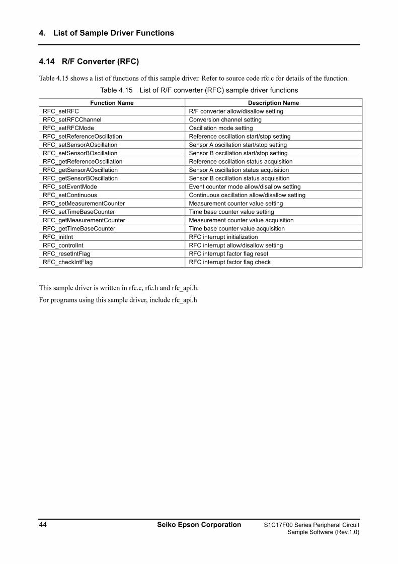
4. List of Sample Driver Functions
4.14 R/F Converter (RFC)
Table 4.15 shows a list of functions of this sample driver. Refer to source code rfc.c for details of the function.
Table 4.15 List of R/F converter (RFC) sample driver functions
Function Name Description Name RFC_setRFC R/F converter allow/disallow setting RFC_setRFCChannel Conversion channel setting RFC_setRFCMode Oscillation mode setting RFC_setReferenceOscillation Reference oscillation start/stop setting RFC_setSensorAOscillation Sensor A oscillation start/stop setting RFC_setSensorBOscillation Sensor B oscillation start/stop setting RFC_getReferenceOscillation Reference oscillation status acquisition RFC_getSensorAOscillation Sensor A oscillation status acquisition RFC_getSensorBOscillation Sensor B oscillation status acquisition RFC_setEventMode Event counter mode allow/disallow setting RFC_setContinuous Continuous oscillation allow/disallow setting RFC_setMeasurementCounter Measurement counter value setting RFC_setTimeBaseCounter Time base counter value setting RFC_getMeasurementCounter Measurement counter value acquisition RFC_getTimeBaseCounter Time base counter value acquisition RFC_initInt RFC interrupt initialization RFC_controlInt RFC interrupt allow/disallow setting RFC_resetIntFlag RFC interrupt factor flag reset RFC_checkIntFlag RFC interrupt factor flag check
This sample driver is written in rfc.c, rfc.h and rfc_api.h.
For programs using this sample driver, include rfc_api.h
44 Seiko Epson Corporation S1C17F00 Series Peripheral Circuit Sample Software (Rev.1.0)
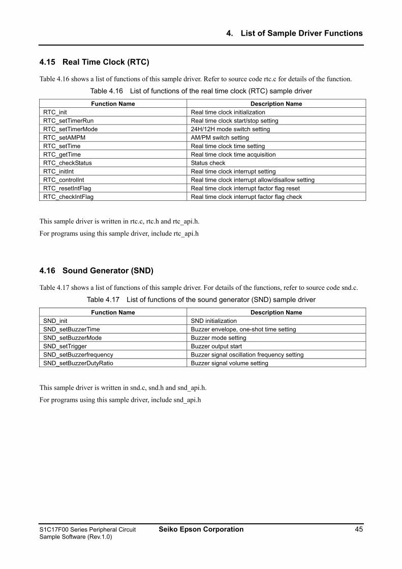
4. List of Sample Driver Functions
4.15 Real Time Clock (RTC)
Table 4.16 shows a list of functions of this sample driver. Refer to source code rtc.c for details of the function.
Table 4.16 List of functions of the real time clock (RTC) sample driver
Function Name Description Name RTC_init Real time clock initialization RTC_setTimerRun Real time clock start/stop setting RTC_setTimerMode 24H/12H mode switch setting RTC_setAMPM AM/PM switch setting RTC_setTime Real time clock time setting RTC_getTime Real time clock time acquisition RTC_checkStatus Status check RTC_initInt Real time clock interrupt setting RTC_controlInt Real time clock interrupt allow/disallow setting RTC_resetIntFlag Real time clock interrupt factor flag reset RTC_checkIntFlag Real time clock interrupt factor flag check
This sample driver is written in rtc.c, rtc.h and rtc_api.h.
For programs using this sample driver, include rtc_api.h
4.16 Sound Generator (SND)
Table 4.17 shows a list of functions of this sample driver. For details of the functions, refer to source code snd.c.
Table 4.17 List of functions of the sound generator (SND) sample driver
Function Name Description Name SND_init SND initialization SND_setBuzzerTime Buzzer envelope, one-shot time setting SND_setBuzzerMode Buzzer mode setting SND_setTrigger Buzzer output start SND_setBuzzerfrequency Buzzer signal oscillation frequency setting SND_setBuzzerDutyRatio Buzzer signal volume setting
This sample driver is written in snd.c, snd.h and snd_api.h.
For programs using this sample driver, include snd_api.h
S1C17F00 Series Peripheral Circuit Seiko Epson Corporation 45 Sample Software (Rev.1.0)
4. List of Sample Driver Functions
4.17 Temperature Detection Circuit (TEM)
Table 4.18 shows a list of functions of this sample driver. For details of the functions, refer to source code tem.c.
Table 4.18 List of temperature detection circuit (TEM) sample driver functions
Function Name Description Name TEM_init TEM initialization TEM_setConversionRun Temperature conversion start/stop setting TEM_setTEMEnable Temperature sensor conversion allow/disallow setting TEM_setConversionTime Sensor output and comparison voltage comparison time settingTEM_getConversionResult Temperature conversion result acquisition TEM_checkStatus TEM status check TEM_initInt Temperature detection circuit interrupt setting TEM_controlInt Temperature detection circuit interrupt allow/disallow setting TEM_resetIntFlag Temperature detection circuit interrupt factor flag reset TEM_checkIntFlag Temperature detection circuit interrupt factor flag check
This sample driver is written in tem.c, tem.h and tem_api.h.
For programs using this sample driver, include tem_api.h
4.18 Theoretical Regulation (TR)
Table 4.19 shows a list of functions of this sample driver. For details of the functions, refer to source code tr.c.
Table 4.19 List of theoretical regulation (TR) sample driver functions
Function Name Description Name TR_setRclockfrequency TR (REGMON output) frequency setting TR_setEnable TR allow/disallow setting TR_setTrigger TR start setting TR_setRegulationValue TR single adjustment amount setting
This sample driver is written in tr.c, tr.h and tr_api.h.
For programs using this sample driver, include tr_api.h
46 Seiko Epson Corporation S1C17F00 Series Peripheral Circuit Sample Software (Rev.1.0)
4. List of Sample Driver Functions
4.19 MISC
Table 4.20 shows a list of functions of this sample driver. For details of the functions, refer to source code misc.c.
Table 4.20 List of MISC sample driver functions
Function Name Description Name MISC_setDebugModeControl Debug mode setting MISC_controlWriteProtect MISC register write protect control MISC_setIRAMSize IRAM size setting MISC_setTTBR Vector table address setting MISC_getPSR PSR acquisition MISC_getIRAMSize IRAM size acquisition
This sample driver is written in misc.c, misc.h and misc_api.h.
For programs using this sample driver, include misc_api.h
4.20 Multiplexer (MUX)
Table 4.21 shows a list of functions of this sample driver. For details of the functions, refer to source code mux.c.
Table 4.21 List of multiplexer (MUX) sample driver functions
Function Name Description Name MUX_init MUX initialization MUX_setSPIport SPI port setting MUX_setUARTport UART port setting MUX_setRFCport RFC port setting MUX_setI2CMport I2C master port setting MUX_setI2CSport I2C slave port setting MUX_setOSCport OSC port setting MUX_setSNDport SND port setting MUX_setDBGport Debug port setting MUX_setT16A2port PWM timer (T16A2) port setting
This sample driver is written in mux.c, mux.h and mux_api.h.
For programs using this sample driver, include mux_api.h
S1C17F00 Series Peripheral Circuit Seiko Epson Corporation 47 Sample Software (Rev.1.0)
4. List of Sample Driver Functions
4.21 Power Supply Control Circuit (VD1)
Table 4.22 shows a list of functions of this sample driver. Refer to source code vd1.c for details of the function.
Table 4.22 List of functions of the power supply control circuit (VD1) sample driver
Function Name Description Name VD1_setMode Heavy load mode setting
This sample driver is written in vd1.c, vd1.h and vd1_api.h.
For programs using this sample driver, include vd1_api.h
48 Seiko Epson Corporation S1C17F00 Series Peripheral Circuit Sample Software (Rev.1.0)
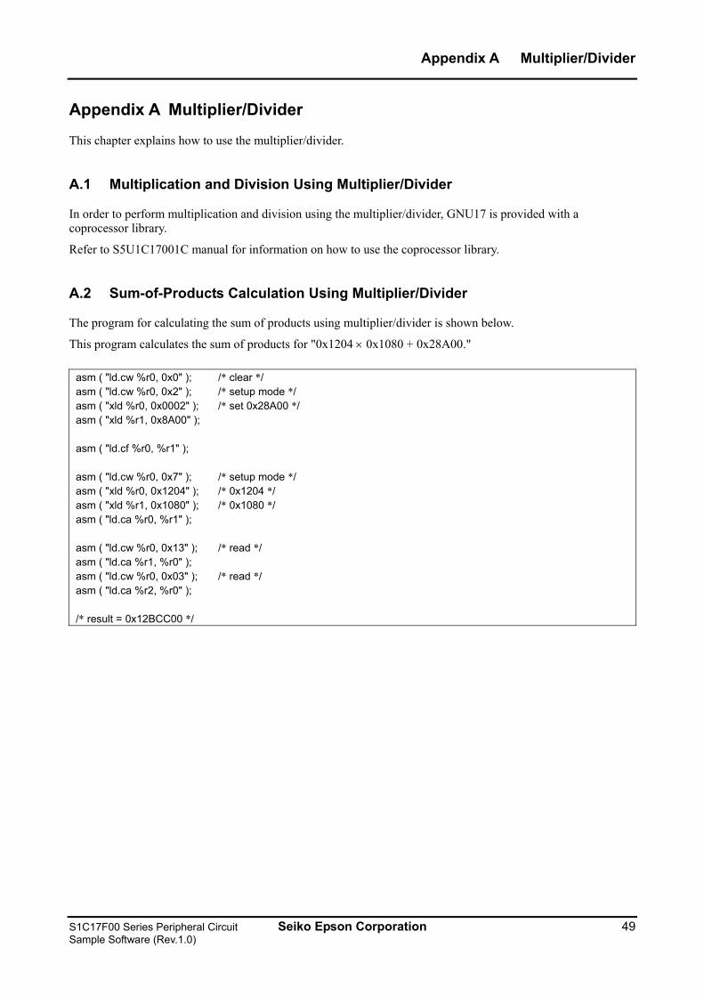
Appendix A Multiplier/Divider
Appendix A Multiplier/Divider
This chapter explains how to use the multiplier/divider.
A.1 Multiplication and Division Using Multiplier/Divider
In order to perform multiplication and division using the multiplier/divider, GNU17 is provided with a coprocessor library.
Refer to S5U1C17001C manual for information on how to use the coprocessor library.
A.2 Sum-of-Products Calculation Using Multiplier/Divider
The program for calculating the sum of products using multiplier/divider is shown below.
This program calculates the sum of products for "0x1204 × 0x1080 + 0x28A00."
asm ( "ld.cw %r0, 0x0" ); /* clear */ asm ( "ld.cw %r0, 0x2" ); /* setup mode */ asm ( "xld %r0, 0x0002" ); /* set 0x28A00 */ asm ( "xld %r1, 0x8A00" ); asm ( "ld.cf %r0, %r1" ); asm ( "ld.cw %r0, 0x7" ); /* setup mode */ asm ( "xld %r0, 0x1204" ); /* 0x1204 */ asm ( "xld %r1, 0x1080" ); /* 0x1080 */ asm ( "ld.ca %r0, %r1" ); asm ( "ld.cw %r0, 0x13" ); /* read */ asm ( "ld.ca %r1, %r0" ); asm ( "ld.cw %r0, 0x03" ); /* read */ asm ( "ld.ca %r2, %r0" ); /* result = 0x12BCC00 */
S1C17F00 Series Peripheral Circuit Seiko Epson Corporation 49 Sample Software (Rev.1.0)
Revision History
Revision History
Attachment-1 Rev. No. Date Page Category Contents Rev 1.0 2011/1/17 All new
50 Seiko Epson Corporation S1C17F00 Series Peripheral Circuit Sample Software (Rev.1.0)
International Sales Operations
AMERICA
EPSON ELECTRONICS AMERICA, INC. 2580 Orchard Parkway, San Jose, CA 95131, USA Phone: +1-800-228-3964 FAX: +1-408-922-0238 EUROPE EPSON EUROPE ELECTRONICS GmbH Riesstrasse 15, 80992 Munich, GERMANY Phone: +49-89-14005-0 FAX: +49-89-14005-110
ASIA EPSON (CHINA) CO., LTD. 7F, Jinbao Bldg., No.89 Jinbao St., Dongcheng District, Beijing 100005, CHINA Phone: +86-10-8522-1199 FAX: +86-10-8522-1125
SHANGHAI BRANCH 7F, Block B, Hi-Tech Bldg., 900 Yishan Road, Shanghai 200233, CHINA Phone: +86-21-5423-5577 FAX: +86-21-5423-4677
SHENZHEN BRANCH 12F, Dawning Mansion, Keji South 12th Road,Hi-Tech Park, Shenzhen 518057, CHINA Phone: +86-755-2699-3828 FAX: +86-755-2699-3838 EPSON HONG KONG LTD. 20/F, Harbour Centre, 25 Harbour Road, Wanchai, Hong Kong Phone: +852-2585-4600 FAX: +852-2827-4346 Telex: 65542 EPSCO HX EPSON TAIWAN TECHNOLOGY & TRADING LTD. 14F, No. 7, Song Ren Road, Taipei 110, TAIWAN Phone: +886-2-8786-6688 FAX: +886-2-8786-6660 EPSON SINGAPORE PTE., LTD. 1 HarbourFront Place, #03-02 HarbourFront Tower One, Singapore 098633 Phone: +65-6586-5500 FAX: +65-6271-3182 SEIKO EPSON CORP. KOREA OFFICE 5F, KLI 63 Bldg., 60 Yoido-dong, Youngdeungpo-Ku, Seoul 150-763, KOREA Phone: +82-2-784-6027 FAX: +82-2-767-3677 SEIKO EPSON CORP. MICRODEVICES OPERATIONS DIVISION Device Sales & Marketing Dept. 421-8, Hino, Hino-shi, Tokyo 191-8501, JAPAN Phone: +81-42-587-5814 FAX: +81-42-587-5117
Document Code: 412043200 First Issue January 2011 in JAPAN